US5546074A - Smoke detector system with self-diagnostic capabilities and replaceable smoke intake canopy - Google Patents
Smoke detector system with self-diagnostic capabilities and replaceable smoke intake canopyDownload PDFInfo
- Publication number
- US5546074A US5546074AUS08/110,131US11013193AUS5546074AUS 5546074 AUS5546074 AUS 5546074AUS 11013193 AUS11013193 AUS 11013193AUS 5546074 AUS5546074 AUS 5546074A
- Authority
- US
- United States
- Prior art keywords
- pegs
- canopy
- smoke
- interior
- radiation
- Prior art date
- Legal status (The legal status is an assumption and is not a legal conclusion. Google has not performed a legal analysis and makes no representation as to the accuracy of the status listed.)
- Expired - Lifetime
Links
- 239000000779smokeSubstances0.000titleclaimsabstractdescription105
- 230000003287optical effectEffects0.000claimsabstractdescription35
- 230000035945sensitivityEffects0.000claimsabstractdescription10
- 230000008859changeEffects0.000claimsabstractdescription7
- 230000005855radiationEffects0.000claimsdescription26
- 230000010354integrationEffects0.000claimsdescription22
- 239000002245particleSubstances0.000claimsdescription18
- 238000012360testing methodMethods0.000claimsdescription8
- 230000000737periodic effectEffects0.000claimsdescription6
- 238000012545processingMethods0.000claimsdescription6
- 230000004044responseEffects0.000claimsdescription6
- 238000005259measurementMethods0.000claimsdescription4
- 230000001902propagating effectEffects0.000claimsdescription2
- 239000000463materialSubstances0.000claims3
- 230000004888barrier functionEffects0.000claims1
- 238000012886linear functionMethods0.000claims1
- 230000006870functionEffects0.000abstractdescription11
- 238000000034methodMethods0.000description21
- 230000008569processEffects0.000description20
- 239000003990capacitorSubstances0.000description12
- 238000010586diagramMethods0.000description7
- 238000004092self-diagnosisMethods0.000description7
- 238000006243chemical reactionMethods0.000description5
- 239000000428dustSubstances0.000description5
- 235000014676Phragmites communisNutrition0.000description4
- 239000000443aerosolSubstances0.000description3
- 238000005070samplingMethods0.000description3
- 239000007921spraySubstances0.000description3
- 241000238631HexapodaSpecies0.000description2
- 230000004397blinkingEffects0.000description2
- 239000000356contaminantSubstances0.000description2
- 238000013461designMethods0.000description2
- 238000010521absorption reactionMethods0.000description1
- 230000004913activationEffects0.000description1
- 230000000295complement effectEffects0.000description1
- 230000001419dependent effectEffects0.000description1
- 238000011156evaluationMethods0.000description1
- 238000005286illuminationMethods0.000description1
- 230000008595infiltrationEffects0.000description1
- 238000001764infiltrationMethods0.000description1
- 238000007689inspectionMethods0.000description1
- 238000009434installationMethods0.000description1
- 230000003993interactionEffects0.000description1
- 230000002452interceptive effectEffects0.000description1
- 239000002991molded plasticSubstances0.000description1
- 238000000465mouldingMethods0.000description1
- 238000005096rolling processMethods0.000description1
- 238000000926separation methodMethods0.000description1
- 230000011664signalingEffects0.000description1
- 238000006467substitution reactionMethods0.000description1
- 238000012795verificationMethods0.000description1
Images


Classifications
- G—PHYSICS
- G08—SIGNALLING
- G08B—SIGNALLING OR CALLING SYSTEMS; ORDER TELEGRAPHS; ALARM SYSTEMS
- G08B29/00—Checking or monitoring of signalling or alarm systems; Prevention or correction of operating errors, e.g. preventing unauthorised operation
- G08B29/18—Prevention or correction of operating errors
- G08B29/20—Calibration, including self-calibrating arrangements
- G—PHYSICS
- G08—SIGNALLING
- G08B—SIGNALLING OR CALLING SYSTEMS; ORDER TELEGRAPHS; ALARM SYSTEMS
- G08B17/00—Fire alarms; Alarms responsive to explosion
- G08B17/10—Actuation by presence of smoke or gases, e.g. automatic alarm devices for analysing flowing fluid materials by the use of optical means
- G08B17/103—Actuation by presence of smoke or gases, e.g. automatic alarm devices for analysing flowing fluid materials by the use of optical means using a light emitting and receiving device
- G08B17/107—Actuation by presence of smoke or gases, e.g. automatic alarm devices for analysing flowing fluid materials by the use of optical means using a light emitting and receiving device for detecting light-scattering due to smoke
- G—PHYSICS
- G08—SIGNALLING
- G08B—SIGNALLING OR CALLING SYSTEMS; ORDER TELEGRAPHS; ALARM SYSTEMS
- G08B17/00—Fire alarms; Alarms responsive to explosion
- G08B17/10—Actuation by presence of smoke or gases, e.g. automatic alarm devices for analysing flowing fluid materials by the use of optical means
- G08B17/11—Actuation by presence of smoke or gases, e.g. automatic alarm devices for analysing flowing fluid materials by the use of optical means using an ionisation chamber for detecting smoke or gas
- G08B17/113—Constructional details
- G—PHYSICS
- G08—SIGNALLING
- G08B—SIGNALLING OR CALLING SYSTEMS; ORDER TELEGRAPHS; ALARM SYSTEMS
- G08B29/00—Checking or monitoring of signalling or alarm systems; Prevention or correction of operating errors, e.g. preventing unauthorised operation
- G08B29/12—Checking intermittently signalling or alarm systems
- G08B29/14—Checking intermittently signalling or alarm systems checking the detection circuits
- G08B29/145—Checking intermittently signalling or alarm systems checking the detection circuits of fire detection circuits
Definitions
- the present inventionrelates to smoke detector systems and, in particular, to a smoke detector system that has internal self-diagnostic capabilities and needs no recalibration upon replacement of its smoke intake canopy.
- a photoelectric smoke detector systemmeasures the ambient smoke conditions of a confined space and activates an alarm in response to the presence of unacceptably high amounts of smoke. This is accomplished by installing in a housing covered by a smoke intake canopy a light-emitting device (“emitter”) and a light sensor (“sensor”) positioned in proximity to measure the amount of light transmitted between them.
- emittera light-emitting device
- sensora light sensor
- a first type of smoke detector systempositions the emitter and sensor so that their lines of sight are collinear. The presence of increasing amounts of smoke increases the attenuation of light passing between the emitter and the sensor. Whenever the amount of light striking the sensor drops below a minimum threshold, the system activates an alarm.
- a second type of smoke detector systempositions the emitter and sensor so that their lines of sight are offset at a sufficiently large angle that very little light propagating from the emitter directly strikes the sensor.
- the presence of increasing amounts of smokeincreases the amount of light scattered toward and striking the sensor. Whenever the amount of light striking the sensor increases above a maximum threshold, the system activates an alarm.
- the emitter and sensorneed initial calibration and periodic testing to ensure their optical response characteristics are within the nominal limits specified.
- Currently available smoke detector systemssuffer from the disadvantage of requiring periodic inspection of system hardware and manual adjustment of electrical components to carry out a calibration sequence.
- the canopy covering the emitter and sensoris an important hardware component that has two competing functions to carry out.
- the canopymust act as an optical block for outside light but permit adequate smoke particle intake and flow into the interior of the canopy for interaction with the emitter and sensor.
- the canopymust also be constructed to prevent the entry of insects and dust, both of which can affect the optical response of the system and its ability to respond to a valid alarm condition.
- the interior of the canopyshould be designed so that secondary reflections of light occurring within the canopy are either directed away from the sensor and out of the canopy or absorbed before they can reach the sensor.
- An object of the inventionis, therefore, to provide a smoke detector system that is capable of performing self-diagnostic functions to determine whether it is within its calibration limits and thereby to eliminate a need for periodic manual calibration testing.
- Another object of the inventionis to provide such a system that accepts a replacement smoke intake canopy without requiring recalibration.
- a further object of the inventionis to provide for such a system a replaceable smoke intake canopy that functions as an optical block for externally infiltrating and internally reflected light and that minimally impedes the flow of smoke particles to the emitter and sensor.
- the present inventionis a self-contained smoke detector system that has internal self-diagnostic capabilities and accepts a replacement smoke intake canopy without a need for recalibration.
- a preferred embodimentincludes a light-emitting diode (“LED”) as the emitter and a photodiode sensor. The LED and photodiode are positioned and shielded so that the absence of smoke results in the photodiode's receiving virtually no light emitted by the LED and the presence of smoke results in the scattering of light emitted by the LED toward the photodiode.
- LEDlight-emitting diode
- the systemincludes a microprocessor-based self-diagnostic circuit that periodically checks the sensitivity of the optical sensor electronics to smoke obscuration level. There is a direct correlation between a change in the clean air voltage output of the photodiode and its sensitivity to the smoke obscuration level. Thus, by setting tolerance limits on the amount of change in voltage measured in clean air, the system can provide an indication of when it has become either under-sensitive or over-sensitive to the ambient smoke obscuration level.
- the systemsamples the amount of smoke present by periodically energizing the LED and then determining the smoke obscuration level.
- An algorithm implemented in software stored in system memorydetermines whether for a time (such as 27 hours) the clean air voltage is outside established sensitivity tolerance limits. Upon determination of an under- or over-sensitivity condition, the system provides an indication that a problem exists with the optical sensor electronics.
- the LED and photodiodereside in a compact housing having a replaceable smoke intake canopy of preferably cylindrical shape with a porous side surface.
- the canopyis specially designed with multiple pegs having multi-faceted surfaces.
- the pegsare angularly spaced about the periphery in the interior of the canopy to function as an optical block for external light infiltrating through the porous side surface of the canopy and to minimize spurious light reflections from the interior of the housing toward the photodiode. This permits the substitution of a replacement canopy of similar design without the need to recalibrate the optical sensor electronics previously calibrated during installation at the factory.
- the pegsare positioned and designed also to form a labyrinth of passageways that permit smoke to flow freely through the interior of the housing.
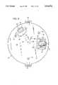
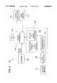
- FIG. 1is a side elevation view of the assembled housing for the smoke detector system of the present invention.
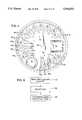
- FIG. 2is an isometric view of the housing of FIG. 1 with its replaceable smoke intake canopy and base disassembled to show the placement of the optical components in the base.
- FIG. 3is plan view of the base shown in FIG. 2.
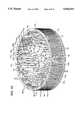
- FIGS. 4A and 4Bare isometric views taken at different vantage points of the interior of the canopy shown in FIG. 2.
- FIG. 5is a plan view of the interior of the canopy shown in FIG. 2.
- FIG. 6is a flow diagram showing the steps performed in the factory during calibration of the smoke detector system.
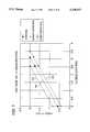
- FIG. 7is a graph of the optical sensor electronics sensitivity, which is expressed as a linear relationship between the level of obscuration and sensor output voltage.
- FIG. 8is a general block diagram of the microprocessor-based circuit that implements the self-diagnostic and calibration functions of the smoke detector system.
- FIG. 9is a block diagram showing in greater detail the variable integrating analog-to-digital converter shown in FIG. 8.
- FIG. 10is a flow diagram showing the self-diagnosis steps carried out by the optical sensor electronics shown in FIG. 8.
- FIGS. 1-5show a preferred embodiment of a smoke detector system housing 10 that includes a circular base 12 covered by a removable smoke intake canopy 14 of cylindrical shape.
- Base 12 and canopy 14are formed of molded plastic whose color is black so as to absorb light incident to it.
- a pair of diametrically opposed clasps 16extend from base 12 and fit over a snap ring 18 encircling the rim of canopy 14 to hold it and base 12 together to form a low profile, unitary housing 10.
- Housing 10has pins 19 that fit into holes in the surface of a circuit board (not shown) that holds the electronic components of the smoke detector system.
- base 12has an inner surface 20 that supports an emitter holder 22 for a light-emitting diode (LED) 24 and a sensor holder 26 for a photodiode 28.
- LED 24 and photodiode 28are angularly positioned on inner surface 20 near the periphery of base 12 so that the lines of sight 30 and 32 of the respective LED 24 and photodiode 28 intersect to form an obtuse angle 34 whose vertex is near the center of base 12.
- Angle 34is preferably about 120°.
- Light-blocking fins 36 and 38 positioned between LED 24 and photodiode 28 and a light shield 40 covering both sides of photodiode 28ensure that light emitted by LED 24 in a clean air environment does not reach photodiode 28.
- a pair of posts 44 extending upwardly from either side of emitter holder 22guide the positioning of canopy 14 over base 12 during assembly of housing 10.
- canopy 14includes a circular top member 62 from which a porous side member 64 depends to define the periphery and interior of canopy 14 and of the assembled housing 10.
- the diameter of top member 62is the same as that of base 12.
- Side member 64includes a large number of ribs 66 angularly spaced apart around the periphery of and disposed perpendicularly to the inner surface 68 of top member 62 to define a slitted surface.
- a set of spaced-apart rings 70 positioned along the lengths of ribs 66encircle the slitted surface defined by ribs 66 to form a large number of small rectangular apertures 72.
- the placement of ribs 66 and rings 70provides side member 64 with a porous surface that serves as a smoke intake filter and a molded-in screen that prevents insects from entering housing 10 and interfering with the operation of LED 24 and photodiode 28.
- Apertures 72are of sufficient size that allows adequate smoke particle intake flow into housing 10.
- the size of apertures 72depends upon the angular spacing between adjacent ribs 66 and the number and spacing of rings 70.
- a housing 10 having a 5.2 centimeter base and a 1.75 centimeter heighthas eighty-eight ribs angularly spaced apart by about 4° and nine equidistantly spaced rings 70 to form 0.8 mm 2 apertures 72.
- the ring 70 positioned farthest from top member 62constitutes snap ring 18.
- the interior of canopy 14contains an array of pegs 80 having multi-faceted surfaces.
- Pegs 80are an integral part of canopy 14, being formed during the molding process.
- Pegs 80are angularly spaced about the periphery of canopy 14 so that their multi-faceted surfaces can perform several functions.
- Pegs 80function as an optical block for external light infiltrating through porous side member 64 of canopy 14, minimize spurious light reflections within the interior of housing 10 toward photodiode 28, and form a labyrinth of passageways for smoke particles to flow freely through the interior of housing 10.
- Pegs 80are preferably arranged in a first group 82 and a second group 84.
- the pegs 80 of first group 82are of smaller surface areas and are positioned nearer to center 86 of canopy 14 than are the pegs 80 of second group 84.
- adjacent pegs 80 in second group 84are separated by a recessed peg 80 in first group 82.
- the pegs 80 of groups 82 and 84are divided into two sets 88 and 90 that are separated by light shield caps 92 and 94.
- Caps 92 and 94mate with the upper surfaces of, respectively, emitter holder 22 of LED 24 and sensor holder 26 of photodiode 28 when housing 10 is assembled. Because of the obtuse angle 34 defined by lines of sight 30 and 32 of LED 24 and photodiode 28, respectively, there are fewer pegs 80 in set 88 than in set 90.
- pegs 80 in first group 82have smaller surface areas than those of the pegs 80 in second group 84, all of pegs 80 are of uniform height measured from top member 62 and have similar profiles. The following description is, therefore, given in general for a peg 80.
- corresponding features of pegs 80 in first group 82have the subscript "1" and in the second group 84 have the subscript "2".
- Each of pegs 80is of elongated shape and has a larger pointed head section 100 and a smaller pointed tail section 102 whose respective apex 104 and apex 106 lie along the same radial line extending from center 86 of canopy 14.
- Apex 104 of head section 100is positioned nearer to side member 64, and apex 106 of tail section 102 is positioned nearer to center 86 of canopy 14.
- a medial portion 108includes concave side surfaces 110 that taper toward the midpoint between apex 104 of head section 100 and apex 106 of tail section 102.
- Head section 100includes flat facets or sides 112 joined at apex 104.
- the surface areas of sides 112are selected collectively to block normally incident light entering apertures 72 from passing to the interior of housing 10.
- each side 112 1is 2.0 mm in length, and sides 112 1 define a 105° angle at apex 104 1 .
- Each side 112 2is 3.2 mm in length, and sides 112 2 define a 105° angle at apex 104 2 .
- Medial portions 108 of the proper lengthblock passage of light not blocked by sides 112.
- Light shield caps 92 and 94 and holders 22 and 26block the passage of light in the places where pegs 80 are not present in canopy 14.
- Tail section 102includes flat facets or sides 114 joined at apex 106.
- the surface areas of sides 114are selected to direct spurious light reflections occurring within housing 10 away from photodiode 28 and toward side member 62 for either absorption or passage outward through apertures 72.
- each side 114 1is 1.9 mm in length, and sides 114 1 define a 60° angle at apex 106 1 .
- Each side 114 2is 1.8 mm in length, and sides 114 2 define a 75° angle at apex 106 2 . This function of tail sections 102 allows with the use of different canopies 14 the achievement of very uniform, low ambient level reflected radiation signals toward photodiode 28.
- Canopy 14can, therefore, be field replaceable and used as a spare part in the event of, for example, breakage, excessive dust build-up over apertures 72 causing reduced smoke infiltration, or excessive dust build-up on pegs 80 causing a higher than nominal clean air voltage.
- the amount of angular separation of adjacent pegs 80, the positioning of a peg. 80 of first group 82 between adjacent pegs 80 of second group 84, and the length of medial portion 108 of pegs 80define the shape of a labyrinth of passageways 116 through which smoke particles flow to and from apertures 72. It is desirable to provide passageways 116 having as small angular deviations as possible so as to not impede smoke particle flow.
- the smoke particles flowing through housing 10reflect toward photodiode 28 the light emitted by LED 24.
- the amount of light sensed by photodiode 28is processed as follows by the electronic circuitry of the smoke detector system.
- FIG. 6is a flow diagram showing the steps performed during calibration in the factory.
- process block 150indicates in the absence of a simulated smoke environment the measurement of a clean air voltage that represents a 0 percent smoke obscuration level.
- the clean air voltageis 0.6 volt.
- Upper and lower tolerance threshold limits for the clean air voltageare also set at nominally ⁇ 42 percent of the clean air voltage measured at calibration.
- Process block 152indicates the adjustment of the gain of the optical sensor electronics. This is accomplished by placing housing 10 in a chamber filled with an aerosol spray to produce a simulated smoke environment at a calibrated level of smoke obscuration. The simulated smoke particles flow through apertures 72 of canopy 14 and reflect toward photodiode 28 a portion of the light emitted by LED 24. Because the number of simulated smoke particles is constant, photodiode 28 produces a constant output voltage in response to the amount of light reflected. The gain of the optical sensor electronics is adjusted by varying the length of time they sample the output voltage of photodiode 28. In a preferred embodiment, a variable integrating analog-to-digital converter, whose operation is described below with reference to FIGS. 8 and 9, performs the gain adjustment by determining an integration time interval that produces an alarm voltage threshold of approximately 2.0 volts for a smoke obscuration level of 3.1 percent per foot.
- Process block 154indicates the determination of an alarm output voltage of photodiode 28 that produces an alarm signal indicative of the presence of an excessive number of smoke particles in a space where housing 10 has been placed.
- the alarm voltage of photodiode 28is fixed and stored in an electrically erasable programmable read-only memory (EEPROM), whose function is described below with reference to FIG. 8.
- EEPROMelectrically erasable programmable read-only memory
- the gain of the optical sensor electronicsis set, and the alarm voltage and the clean air voltage and its upper and lower tolerance limit voltages are stored in the EEPROM.
- the EEPROMThere is a linear relationship between the sensor output voltage and the level of obscuration, which relationship can be expressed as
- yrepresents the sensor output voltage
- mrepresents the gain
- brepresents the clean air voltage
- the gainis defined as the sensor output voltage per percent obscuration per foot; therefore, the gain is unaffected by a build-up of dust or other contaminants. This property enables the self-diagnostic capabilities implemented in the present invention.
- the build-up of dust or other contaminantscauses the ambient clean air voltage to rise above or fall below the nominal clean air voltage stored in the EEPROM.
- the smoke detector systemWhenever the clean air voltage measured by photodetector 28 rises, the smoke detector system becomes more sensitive in that it will produce an alarm signal at a smoke obscuration level that is less than the nominal value of 3.1 percent per foot. Conversely, whenever the clean air voltage measured by photodiode 28 falls below the clean air voltage measured at calibration, the smoke detector system will become less sensitive in that it will produce an alarm signal at a smoke obscuration level that is greater than the nominal value.
- FIG. 7shows that changes in the clean air voltage measured over time does not affect the gain of the optical sensor electronics.
- Straight lines 160, 162, and 164represent, respectively, nominal, over-sensitivity, and under-sensitivity conditions. There is, therefore, a direct correlation between a change in clean air voltage and a change in sensitivity to an alarm condition.
- the smoke detector systemcan indicate when it has become under-sensitive or over-sensitive in its measurement of ambient smoke obscuration levels.
- the smoke detector systemTo perform self-diagnosis to determine whether an under- or over-sensitivity condition or an alarm condition exists, the smoke detector system periodically samples the ambient smoke levels. To prevent short-term changes in clean air voltage that do not represent out-of-sensitivity indications, the present invention includes a microprocessor-based circuit that is implemented with an algorithm to determine whether the clean air voltage is outside of predetermined tolerance limits for a preferred period of approximately 27 hours. The micro-processor-based circuit and the algorithm implemented in it to perform self-diagnosis is described with reference to FIGS. 8-10.
- Converter subcircuit 208takes an output voltage sample and integrates it during an integration time interval set during the gain calibration step discussed with reference to process block 152 of FIG. 6. Upon conclusion of each integration time interval, subcircuit 208 converts to a digital value the analog voltage representative of the photodetector output voltage sample taken.
- Microprocessor 202receives the digital value and compares it to the alarm voltage and sensitivity tolerance limit voltages established and stored in EEPROM 204 during calibration.
- the processing of the integrator voltages presented by subcircuit 208is carried out by microprocessor 202 in accordance with an algorithm implemented as instructions stored in EEPROM 204. The processing steps of this algorithm are described below with reference to FIG. 10.
- Microprocessor 202causes continuous illumination of a visible light-emitting diode (LED) 210 to indicate an alarm condition and performs a manually operated self-diagnosis test in response to an operator's activation of a reed switch 212.
- a clock oscillator 214having a preferred output frequency of 500 kHz provides the timing standard for the overall operation of circuit 200.
- FIG. 9shows in greater detail the components of variable integrating analog-to-digital converter subcircuit 208.
- the followingis a description of operation of converter subcircuit 208 with particular focus on the processing it carries out during calibration to determine the integration time interval.
- preamplifier 206conditions the output voltage samples of photodetector 28 and delivers them to a programmable integrator 216 that includes an input shift register 218, an integrator upcounter 220, and a dual-slope switched capacitor integrator 222. During each 0.4 millisecond sampling period, an input capacitor of integrator 222 accumulates the voltage appearing across the output of preamplifier 206. Integrator 222 then transfers the sample voltage acquired by the input capacitor to an output capacitor.
- shift register 218receives under control of microprocessor 202 an 8-bit serial digital word representing the integration time interval. The least significant bit corresponds to 9 millivolts, with 2.3 volts representing the full scale voltage for the 8-bit word. Shift register 218 provides as a preset to integrator up-counter 220 the complement of the integration time interval word.
- a 250 kHz clock produced at the output of a divide-by-two counter 230 driven by 500 kHz clock oscillator 214causes integrator up-counter 220 to count up to zero from the complemented integration time interval word.
- the time during which up-counter 220 countsdefines the integration time interval during which integrator 222 accumulates across an output capacitor an analog voltage representative of the photodetector output voltage sample acquired by the input capacitor.
- the value of the analog voltage stored across the output capacitoris determined by the output voltage of photodiode 28 and the number of counts stored in integrator counter 220.
- integrator up-counter 220Upon completion of the integration time interval, integrator up-counter 220 stops counting at zero.
- An analog-to-digital converter 232then converts to a digital value the analog voltage stored across the output capacitor of integrator 222.
- Analog-to-digital converter 232includes a comparator amplifier 234 that receives at its noninverting input the integrator voltage across the output capacitor and at its inverting input a reference voltage, which in the preferred embodiment is 300 millivolts, a system virtual ground.
- a comparator buffer amplifier 236conditions the output of comparator 234 and provides a count enable signal to a conversion up-counter 238, which begins counting up after integrator up-counter 220 stops counting at zero and continues to count up as long as the count enable signal is present.
- integrator 222discharges the voltage across the output capacitor to a third capacitor while conversion up-counter 238 continues to count. Such counting continues until the integrator voltage across the output capacitor discharges below the +300 millivolt threshold of comparator 234, thereby causing the removal of the count enable signal.
- the contents of conversion up-counter 238are then shifted to an output shift register 240, which provides to microprocessor 202 an 8-bit serial digital word representative of the integrator voltage for processing in accordance with the mode of operation of the smoke detector system.
- modes of operationinclude calibration, in-service self-diagnosis, and self-test.
- the smoke detector systemdetermines the gain of the optical sensor electronics by substituting trial integration time interval words of different weighted values as presets to integrator up-counter 220 to obtain the integration time interval necessary to produce the desired alarm voltage for a known smoke obscuration level.
- a preferred desired alarm voltageof about 2.0 volts for a 3.1 percent per foot obscuration level is stored in EEPROM 204.
- the output of photodiode 28is a fixed voltage when housing 10 is placed in an aerosol spray chamber that produces the 3.1 percent per foot obscuration level representing the alarm condition. Because different photodiodes 28 differ somewhat in their output voltages, determining the integration time interval that produces an integrator voltage equal to the alarm voltage sets the gain of the system. Thus, different counting time intervals for integrator up-counter 220 produce different integrator voltages stored in shift register 240.
- the process of providing trial integration time intervals to shift register 218 and integrator up-counter 220 during calibrationcan be accomplished using a microprocessor emulator with the optical sensor electronics placed in the aerosol spray chamber.
- Gain calibrationis complete upon determination of an integration time interval word that produces in shift register 240 an 8-bit digital word corresponding to the alarm voltage.
- the integration time interval wordis stored in EEPROM 204 as the gain factor.
- integrator 222changes during acquisition of output voltage samples for different optical sensors but that the final magnitude of the output voltage of integrator 222 is dependent upon the input voltage and integration time.
- the slope of the analog-to-digital conversionis, however, always the same. This is the reason why integrator 222 is designated as being of a dual-slope type.
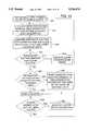
- FIG. 10is a flow diagram showing the self-diagnosis processing steps the smoke detector system carries out during in-service operation.
- process block 250indicates that during in-service operation, microprocessor 202 causes application of electrical power to LED 24 in intervals of 9 seconds to sample its output voltage over the previously determined integration time interval stored in EEPROM 204. The sampling of every 9 seconds reduces the steady-state electrical power consumed by circuit 100.
- Process block 252indicates that after each integration time interval, microprocessor 202 reads the just acquired integrator voltage stored in output shift register 240.
- Process block 254indicates the comparison by microprocessor 202 of the acquired integrator voltage against the alarm voltage and against the upper and lower tolerance limits of the clean air voltage, all of which are preassigned and stored in EEPROM 204. These comparisons are done sequentially by microprocessor 202.
- Decision block 256represents a determination of whether the acquired integrator voltage exceeds the stored alarm voltage. If so, microprocessor 202 provides a continuous signal to an alarm announcing the presence of excessive smoke, as indicated by process block 258. If not so, microprocessor 202 performs the next comparison.
- Decision block 260represents a determination of whether the acquired integrator voltage falls within the stored clean air voltage tolerance limits. If so, the smoke detector system continues to acquire the next output voltage sample of photodiode 28 and, as indicated by process block 262, a counter with a 2-count modulus monitors the occurrence of two consecutive acquired integrator voltages that fall within the clean air voltage tolerance limits. This counter is part of microprocessor 202. If not so, a counter is indexed by one count, as indicated by process block 264. However, each time two consecutive integrator voltages appear, the 2-count modulus counter resets the counter indicated by process block 264.
- Decision block 266represents a determination of whether the number of counts accumulated in the counter of process block 264 exceeds 10,752 counts, which corresponds to consecutive integrator voltage samples in out-of-tolerance limit conditions for each of 9 second intervals over 27 hours. If so, microprocessor 202 provides a low duty-cycle blinking signal to LED 210, as indicated in process block 268. Skilled persons will appreciate that other signaling techniques, such as an audible alarm or a relay output, may be used. The blinking signal indicates that the optical sensor electronics have changed such that the clean air voltage has drifted out of calibration for either under- or over-sensitivity and need to be attended to. If the count in the counter of process block 264 does not exceed 10,752 counts, the smoke detector system continues to acquire the next output voltage sample of photodiode 28.
- the self-diagnosis algorithmprovides, therefore, a rolling 27-hour out-of-tolerance measurement period that is restarted whenever there are two consecutive appearances of integrator voltages within the clean air voltage tolerance limits.
- the smoke detector systemmonitors its own operational status, without a need for manual evaluation of its internal functional status.
- Reed switch 212is directly connected to microprocessor 202 to provide a self-test capability that together with the labyrinth passageway design of pegs 80 in canopy 14 permits on-site verification of an absence of an unserviceable hardware fault.
- an operatorholds a magnet near housing 10 to close reed switch 212.
- Closing reed switch 212activates a self-test program stored in EEPROM 204.
- the self-test programcauses microprocessor 202 to apply a voltage to photodiode 28, read the integrator voltage stored in output shift register 240, and compare it to the clean air voltage and its upper and lower tolerance limits in a manner similar to that described with reference to process blocks 250, 252, and 254 of FIG. 10.
- the self-test programthen causes microprocessor 202 to blink LED 210 two or three times, four to seven times, or eight or nine times if the optical sensor electronics are under-sensitive, within the sensitivity tolerance limits, or over-sensitive, respectively. If none of the above conditions is met, LED 210 blinks one time to indicate an unserviceable hardware fault.
Landscapes
- Physics & Mathematics (AREA)
- General Physics & Mathematics (AREA)
- Engineering & Computer Science (AREA)
- Computer Security & Cryptography (AREA)
- Chemical & Material Sciences (AREA)
- Analytical Chemistry (AREA)
- Business, Economics & Management (AREA)
- Emergency Management (AREA)
- Fire-Detection Mechanisms (AREA)
- Investigating Or Analysing Materials By Optical Means (AREA)
Abstract
Description
y=m*x+b,
Claims (43)
Priority Applications (14)
| Application Number | Priority Date | Filing Date | Title |
|---|---|---|---|
| US08/110,131US5546074A (en) | 1993-08-19 | 1993-08-19 | Smoke detector system with self-diagnostic capabilities and replaceable smoke intake canopy |
| IL11068094AIL110680A0 (en) | 1993-08-19 | 1994-08-16 | Smoke detector system with self-diagnostic capabilities and replaceable smoke intake canopy |
| PCT/US1994/009286WO1995005648A2 (en) | 1993-08-19 | 1994-08-17 | Smoke detector system with self-diagnostic capabilities and replaceable smoke intake canopy |
| EP94927924AEP0714541B1 (en) | 1993-08-19 | 1994-08-17 | Self-diagnostic smoke detector and method of verification thereof |
| AU77150/94AAU7715094A (en) | 1993-08-19 | 1994-08-17 | Smoke detector system with self-diagnostic capabilities and replaceable smoke intake canopy |
| ES94927924TES2166785T3 (en) | 1993-08-19 | 1994-08-17 | SELF-DIAGNOSTIC SMOKE DETECTOR AND VERIFICATION METHOD OF THE SAME. |
| CA002169741ACA2169741C (en) | 1993-08-19 | 1994-08-17 | Smoke detector system with self-diagnostic capabilities and replaceable smoke intake canopy |
| AT94927924TATE207646T1 (en) | 1993-08-19 | 1994-08-17 | SELF-DIAGNOSIS SMOKE DETECTOR AND METHOD FOR CHECKING THE SAME |
| DE69428800TDE69428800T2 (en) | 1993-08-19 | 1994-08-17 | SMOKE DETECTOR WITH SELF-DIAGNOSIS AND METHOD FOR CHECKING IT |
| US08/695,748US5708414A (en) | 1993-08-19 | 1996-08-12 | Sensitivity fault indication technique implemented in smoke detector system with self-diagnostic capabilities |
| US08/696,304US5821866A (en) | 1993-08-19 | 1996-08-13 | Self-diagnosing smoke detector assembly |
| US09/170,474US5936533A (en) | 1993-08-19 | 1998-10-13 | Method of automatic verification of smoke detector operation within calibration limits |
| US09/366,469US6396405B1 (en) | 1993-08-19 | 1999-08-03 | Automatic verification of smoke detector operation within calibration limits |
| US10/155,857US6756906B2 (en) | 1993-08-19 | 2002-05-24 | Self-diagnostic smoke detector |
Applications Claiming Priority (1)
| Application Number | Priority Date | Filing Date | Title |
|---|---|---|---|
| US08/110,131US5546074A (en) | 1993-08-19 | 1993-08-19 | Smoke detector system with self-diagnostic capabilities and replaceable smoke intake canopy |
Related Child Applications (2)
| Application Number | Title | Priority Date | Filing Date |
|---|---|---|---|
| US08/695,748Continuation-In-PartUS5708414A (en) | 1993-08-19 | 1996-08-12 | Sensitivity fault indication technique implemented in smoke detector system with self-diagnostic capabilities |
| US08/696,304DivisionUS5821866A (en) | 1993-08-19 | 1996-08-13 | Self-diagnosing smoke detector assembly |
Publications (1)
| Publication Number | Publication Date |
|---|---|
| US5546074Atrue US5546074A (en) | 1996-08-13 |
Family
ID=22331371
Family Applications (4)
| Application Number | Title | Priority Date | Filing Date |
|---|---|---|---|
| US08/110,131Expired - LifetimeUS5546074A (en) | 1993-08-19 | 1993-08-19 | Smoke detector system with self-diagnostic capabilities and replaceable smoke intake canopy |
| US08/695,748Expired - LifetimeUS5708414A (en) | 1993-08-19 | 1996-08-12 | Sensitivity fault indication technique implemented in smoke detector system with self-diagnostic capabilities |
| US08/696,304Expired - LifetimeUS5821866A (en) | 1993-08-19 | 1996-08-13 | Self-diagnosing smoke detector assembly |
| US09/170,474Expired - LifetimeUS5936533A (en) | 1993-08-19 | 1998-10-13 | Method of automatic verification of smoke detector operation within calibration limits |
Family Applications After (3)
| Application Number | Title | Priority Date | Filing Date |
|---|---|---|---|
| US08/695,748Expired - LifetimeUS5708414A (en) | 1993-08-19 | 1996-08-12 | Sensitivity fault indication technique implemented in smoke detector system with self-diagnostic capabilities |
| US08/696,304Expired - LifetimeUS5821866A (en) | 1993-08-19 | 1996-08-13 | Self-diagnosing smoke detector assembly |
| US09/170,474Expired - LifetimeUS5936533A (en) | 1993-08-19 | 1998-10-13 | Method of automatic verification of smoke detector operation within calibration limits |
Country Status (9)
| Country | Link |
|---|---|
| US (4) | US5546074A (en) |
| EP (1) | EP0714541B1 (en) |
| AT (1) | ATE207646T1 (en) |
| AU (1) | AU7715094A (en) |
| CA (1) | CA2169741C (en) |
| DE (1) | DE69428800T2 (en) |
| ES (1) | ES2166785T3 (en) |
| IL (1) | IL110680A0 (en) |
| WO (1) | WO1995005648A2 (en) |
Cited By (126)
| Publication number | Priority date | Publication date | Assignee | Title |
|---|---|---|---|---|
| US5699043A (en)* | 1993-07-12 | 1997-12-16 | Detection Systems, Inc. | Individual smoke detector with sensitivity calibration and monitoring |
| US5705988A (en)* | 1996-07-08 | 1998-01-06 | Detection Systems, Inc. | Photoelectric smoke detector with count based A/D and D/A converter |
| US5708414A (en)* | 1993-08-19 | 1998-01-13 | Sentrol, Inc. | Sensitivity fault indication technique implemented in smoke detector system with self-diagnostic capabilities |
| US5751218A (en)* | 1996-07-19 | 1998-05-12 | Simplex Time Recorder Company | Smoke detector housing for improved smoke collection |
| US5798701A (en)* | 1994-08-26 | 1998-08-25 | Slc Technologies, Inc. | Self-adjusting smoke detector with self-diagnostic capabilities |
| US5831537A (en)* | 1997-10-27 | 1998-11-03 | Slc Technologies, Inc. | Electrical current saving combined smoke and fire detector |
| US6057774A (en)* | 1999-01-21 | 2000-05-02 | Brk Brands, Inc. | Smoke alarm with anti-dust screen |
| US6195014B1 (en)* | 1999-04-30 | 2001-02-27 | Nittan Company Limited | Fire detector |
| EP1006500A3 (en)* | 1998-12-04 | 2001-04-11 | Pittway Corporation | Smoke detector with aspiration unit and flow sensor |
| US6225910B1 (en) | 1999-12-08 | 2001-05-01 | Gentex Corporation | Smoke detector |
| US20020089426A1 (en)* | 2001-01-09 | 2002-07-11 | Simplexgrinnell Lp | Smoke chamber |
| US6424257B1 (en) | 2000-04-18 | 2002-07-23 | Pittway Corporation | Bidirectional communication between control element and electrical devices |
| DE20205194U1 (en) | 2002-04-03 | 2002-08-08 | Everday Technology Co., Ltd., Taipeh/T'ai-pei | Smoke collection case |
| US6445292B1 (en) | 2000-04-12 | 2002-09-03 | Pittway Corporation | Processor based wireless detector |
| EP1100061A3 (en)* | 1999-11-10 | 2002-12-11 | Nohmi Bosai Ltd. | Photoelectric smoke detecting apparatus |
| EP1253566A3 (en)* | 2001-04-24 | 2003-05-07 | Matsushita Electric Works, Ltd. | Fire detector unit |
| US20030127585A1 (en)* | 2002-01-08 | 2003-07-10 | Scott Lang | Obscuration detector |
| US20030197618A1 (en)* | 2002-04-23 | 2003-10-23 | Alex Hsieh | Smoke collector case |
| US20040063154A1 (en)* | 2002-08-23 | 2004-04-01 | Booth David K. | Rapidly responding, false detection immune alarm signal producing smoke detector |
| AU772120B2 (en)* | 1999-03-25 | 2004-04-08 | Fireangel Limited | Smoke detector housing |
| US6756905B2 (en)* | 1999-12-31 | 2004-06-29 | Digital Security Controls Ltd. | Photoelectric smoke detector and chamber therefor |
| US20050057366A1 (en)* | 1999-12-08 | 2005-03-17 | Kadwell Brian J. | Compact particle sensor |
| US20050134468A1 (en)* | 2003-12-23 | 2005-06-23 | Thomas Robert M. | Optical smoke detector and method of cleaning |
| US20060007010A1 (en)* | 2004-07-09 | 2006-01-12 | Tyco Safety Products Canada Ltd. | Smoke detector calibration |
| US20060007009A1 (en)* | 2002-06-20 | 2006-01-12 | Siemens Building Technologies Ag | Fire detector |
| US20060261967A1 (en)* | 2002-08-23 | 2006-11-23 | Marman Douglas H | Smoke detector and method of detecting smoke |
| US20080018485A1 (en)* | 2006-07-18 | 2008-01-24 | Gentex Corporation | Optical particle detectors |
| US20080174443A1 (en)* | 2007-01-18 | 2008-07-24 | Michael Edward La Vigne | Smoke detector guard concentrator |
| US20100085199A1 (en)* | 2008-10-03 | 2010-04-08 | Universal Security Instruments, Inc. | Dynamic Alarm Sensitivity Adjustment and Auto-Calibrating Smoke Detection |
| US20110018726A1 (en)* | 2008-10-03 | 2011-01-27 | Universal Security Instruments, Inc. | Dynamic Alarm Sensitivity Adjustment and Auto-Calibrating Smoke Detection |
| JP2011044104A (en)* | 2009-08-24 | 2011-03-03 | Panasonic Electric Works Co Ltd | Smoke detector |
| US20110187543A1 (en)* | 2010-02-04 | 2011-08-04 | Linda Russo | Home safety 911 system |
| US8395501B2 (en) | 2010-11-23 | 2013-03-12 | Universal Security Instruments, Inc. | Dynamic alarm sensitivity adjustment and auto-calibrating smoke detection for reduced resource microprocessors |
| US20140291525A1 (en)* | 2013-03-29 | 2014-10-02 | N.E.T. Srl | Variable geometry optical gas detector |
| US20150170489A1 (en)* | 2012-09-21 | 2015-06-18 | Google Inc. | Detector unit and sensing chamber therefor |
| US20160274759A1 (en) | 2008-08-25 | 2016-09-22 | Paul J. Dawes | Security system with networked touchscreen and gateway |
| US10051078B2 (en) | 2007-06-12 | 2018-08-14 | Icontrol Networks, Inc. | WiFi-to-serial encapsulation in systems |
| US10062273B2 (en) | 2010-09-28 | 2018-08-28 | Icontrol Networks, Inc. | Integrated security system with parallel processing architecture |
| US10062245B2 (en) | 2005-03-16 | 2018-08-28 | Icontrol Networks, Inc. | Cross-client sensor user interface in an integrated security network |
| US10079839B1 (en) | 2007-06-12 | 2018-09-18 | Icontrol Networks, Inc. | Activation of gateway device |
| US10078958B2 (en) | 2010-12-17 | 2018-09-18 | Icontrol Networks, Inc. | Method and system for logging security event data |
| US10091014B2 (en) | 2005-03-16 | 2018-10-02 | Icontrol Networks, Inc. | Integrated security network with security alarm signaling system |
| US10127801B2 (en) | 2005-03-16 | 2018-11-13 | Icontrol Networks, Inc. | Integrated security system with parallel processing architecture |
| US10142166B2 (en) | 2004-03-16 | 2018-11-27 | Icontrol Networks, Inc. | Takeover of security network |
| US10142394B2 (en) | 2007-06-12 | 2018-11-27 | Icontrol Networks, Inc. | Generating risk profile using data of home monitoring and security system |
| US10142392B2 (en) | 2007-01-24 | 2018-11-27 | Icontrol Networks, Inc. | Methods and systems for improved system performance |
| US10140840B2 (en) | 2007-04-23 | 2018-11-27 | Icontrol Networks, Inc. | Method and system for providing alternate network access |
| US10156959B2 (en) | 2005-03-16 | 2018-12-18 | Icontrol Networks, Inc. | Cross-client sensor user interface in an integrated security network |
| US10156831B2 (en) | 2004-03-16 | 2018-12-18 | Icontrol Networks, Inc. | Automation system with mobile interface |
| US10200504B2 (en) | 2007-06-12 | 2019-02-05 | Icontrol Networks, Inc. | Communication protocols over internet protocol (IP) networks |
| US10237237B2 (en) | 2007-06-12 | 2019-03-19 | Icontrol Networks, Inc. | Communication protocols in integrated systems |
| US10237806B2 (en) | 2009-04-30 | 2019-03-19 | Icontrol Networks, Inc. | Activation of a home automation controller |
| US10313303B2 (en) | 2007-06-12 | 2019-06-04 | Icontrol Networks, Inc. | Forming a security network including integrated security system components and network devices |
| US10339791B2 (en) | 2007-06-12 | 2019-07-02 | Icontrol Networks, Inc. | Security network integrated with premise security system |
| US10348575B2 (en) | 2013-06-27 | 2019-07-09 | Icontrol Networks, Inc. | Control system user interface |
| US10365810B2 (en) | 2007-06-12 | 2019-07-30 | Icontrol Networks, Inc. | Control system user interface |
| US10380871B2 (en) | 2005-03-16 | 2019-08-13 | Icontrol Networks, Inc. | Control system user interface |
| US10382452B1 (en) | 2007-06-12 | 2019-08-13 | Icontrol Networks, Inc. | Communication protocols in integrated systems |
| US10389736B2 (en) | 2007-06-12 | 2019-08-20 | Icontrol Networks, Inc. | Communication protocols in integrated systems |
| US10423309B2 (en) | 2007-06-12 | 2019-09-24 | Icontrol Networks, Inc. | Device integration framework |
| US10498830B2 (en) | 2007-06-12 | 2019-12-03 | Icontrol Networks, Inc. | Wi-Fi-to-serial encapsulation in systems |
| US10522026B2 (en) | 2008-08-11 | 2019-12-31 | Icontrol Networks, Inc. | Automation system user interface with three-dimensional display |
| US10523689B2 (en) | 2007-06-12 | 2019-12-31 | Icontrol Networks, Inc. | Communication protocols over internet protocol (IP) networks |
| US10530839B2 (en) | 2008-08-11 | 2020-01-07 | Icontrol Networks, Inc. | Integrated cloud system with lightweight gateway for premises automation |
| US10559193B2 (en) | 2002-02-01 | 2020-02-11 | Comcast Cable Communications, Llc | Premises management systems |
| US10616075B2 (en) | 2007-06-12 | 2020-04-07 | Icontrol Networks, Inc. | Communication protocols in integrated systems |
| US10666523B2 (en) | 2007-06-12 | 2020-05-26 | Icontrol Networks, Inc. | Communication protocols in integrated systems |
| US10721087B2 (en) | 2005-03-16 | 2020-07-21 | Icontrol Networks, Inc. | Method for networked touchscreen with integrated interfaces |
| US10747216B2 (en) | 2007-02-28 | 2020-08-18 | Icontrol Networks, Inc. | Method and system for communicating with and controlling an alarm system from a remote server |
| US10785319B2 (en) | 2006-06-12 | 2020-09-22 | Icontrol Networks, Inc. | IP device discovery systems and methods |
| US10841381B2 (en) | 2005-03-16 | 2020-11-17 | Icontrol Networks, Inc. | Security system with networked touchscreen |
| DE102019121063A1 (en)* | 2019-08-05 | 2021-02-11 | Minimax Viking Research & Development Gmbh | Housing for a detection unit for the optical detection of smoke particles |
| US10979389B2 (en) | 2004-03-16 | 2021-04-13 | Icontrol Networks, Inc. | Premises management configuration and control |
| US10999254B2 (en) | 2005-03-16 | 2021-05-04 | Icontrol Networks, Inc. | System for data routing in networks |
| US11089122B2 (en) | 2007-06-12 | 2021-08-10 | Icontrol Networks, Inc. | Controlling data routing among networks |
| US11113950B2 (en) | 2005-03-16 | 2021-09-07 | Icontrol Networks, Inc. | Gateway integrated with premises security system |
| US11146637B2 (en) | 2014-03-03 | 2021-10-12 | Icontrol Networks, Inc. | Media content management |
| US11153266B2 (en) | 2004-03-16 | 2021-10-19 | Icontrol Networks, Inc. | Gateway registry methods and systems |
| US11182060B2 (en) | 2004-03-16 | 2021-11-23 | Icontrol Networks, Inc. | Networked touchscreen with integrated interfaces |
| US11201755B2 (en) | 2004-03-16 | 2021-12-14 | Icontrol Networks, Inc. | Premises system management using status signal |
| US11212192B2 (en) | 2007-06-12 | 2021-12-28 | Icontrol Networks, Inc. | Communication protocols in integrated systems |
| US11218878B2 (en) | 2007-06-12 | 2022-01-04 | Icontrol Networks, Inc. | Communication protocols in integrated systems |
| EP3940662A1 (en)* | 2020-07-02 | 2022-01-19 | Honeywell International Inc. | Self-calibrating fire sensing device |
| US11240059B2 (en) | 2010-12-20 | 2022-02-01 | Icontrol Networks, Inc. | Defining and implementing sensor triggered response rules |
| US11237714B2 (en) | 2007-06-12 | 2022-02-01 | Control Networks, Inc. | Control system user interface |
| US11244545B2 (en) | 2004-03-16 | 2022-02-08 | Icontrol Networks, Inc. | Cross-client sensor user interface in an integrated security network |
| US11258625B2 (en) | 2008-08-11 | 2022-02-22 | Icontrol Networks, Inc. | Mobile premises automation platform |
| US11277465B2 (en) | 2004-03-16 | 2022-03-15 | Icontrol Networks, Inc. | Generating risk profile using data of home monitoring and security system |
| US11310199B2 (en) | 2004-03-16 | 2022-04-19 | Icontrol Networks, Inc. | Premises management configuration and control |
| US11316753B2 (en) | 2007-06-12 | 2022-04-26 | Icontrol Networks, Inc. | Communication protocols in integrated systems |
| US11316958B2 (en) | 2008-08-11 | 2022-04-26 | Icontrol Networks, Inc. | Virtual device systems and methods |
| US11343380B2 (en) | 2004-03-16 | 2022-05-24 | Icontrol Networks, Inc. | Premises system automation |
| US11368327B2 (en) | 2008-08-11 | 2022-06-21 | Icontrol Networks, Inc. | Integrated cloud system for premises automation |
| US11398147B2 (en) | 2010-09-28 | 2022-07-26 | Icontrol Networks, Inc. | Method, system and apparatus for automated reporting of account and sensor zone information to a central station |
| US11405463B2 (en) | 2014-03-03 | 2022-08-02 | Icontrol Networks, Inc. | Media content management |
| US11424980B2 (en) | 2005-03-16 | 2022-08-23 | Icontrol Networks, Inc. | Forming a security network including integrated security system components |
| US11423756B2 (en) | 2007-06-12 | 2022-08-23 | Icontrol Networks, Inc. | Communication protocols in integrated systems |
| US11451409B2 (en) | 2005-03-16 | 2022-09-20 | Icontrol Networks, Inc. | Security network integrating security system and network devices |
| US11489812B2 (en) | 2004-03-16 | 2022-11-01 | Icontrol Networks, Inc. | Forming a security network including integrated security system components and network devices |
| US11496568B2 (en) | 2005-03-16 | 2022-11-08 | Icontrol Networks, Inc. | Security system with networked touchscreen |
| US11582065B2 (en) | 2007-06-12 | 2023-02-14 | Icontrol Networks, Inc. | Systems and methods for device communication |
| US11601810B2 (en) | 2007-06-12 | 2023-03-07 | Icontrol Networks, Inc. | Communication protocols in integrated systems |
| US11615697B2 (en) | 2005-03-16 | 2023-03-28 | Icontrol Networks, Inc. | Premise management systems and methods |
| US11646907B2 (en) | 2007-06-12 | 2023-05-09 | Icontrol Networks, Inc. | Communication protocols in integrated systems |
| US20230146813A1 (en)* | 2017-10-30 | 2023-05-11 | Carrier Corporation | Compensator in a detector device |
| US11677577B2 (en) | 2004-03-16 | 2023-06-13 | Icontrol Networks, Inc. | Premises system management using status signal |
| US11700142B2 (en) | 2005-03-16 | 2023-07-11 | Icontrol Networks, Inc. | Security network integrating security system and network devices |
| US11706279B2 (en) | 2007-01-24 | 2023-07-18 | Icontrol Networks, Inc. | Methods and systems for data communication |
| US11706045B2 (en) | 2005-03-16 | 2023-07-18 | Icontrol Networks, Inc. | Modular electronic display platform |
| US20230252871A1 (en)* | 2022-02-07 | 2023-08-10 | Pixart Imaging Inc. | Smoke detection device with preferred detection accuracy |
| US11729255B2 (en) | 2008-08-11 | 2023-08-15 | Icontrol Networks, Inc. | Integrated cloud system with lightweight gateway for premises automation |
| US11750414B2 (en) | 2010-12-16 | 2023-09-05 | Icontrol Networks, Inc. | Bidirectional security sensor communication for a premises security system |
| US11758026B2 (en) | 2008-08-11 | 2023-09-12 | Icontrol Networks, Inc. | Virtual device systems and methods |
| US11792330B2 (en) | 2005-03-16 | 2023-10-17 | Icontrol Networks, Inc. | Communication and automation in a premises management system |
| US11792036B2 (en) | 2008-08-11 | 2023-10-17 | Icontrol Networks, Inc. | Mobile premises automation platform |
| US11811845B2 (en) | 2004-03-16 | 2023-11-07 | Icontrol Networks, Inc. | Communication protocols over internet protocol (IP) networks |
| US11816323B2 (en) | 2008-06-25 | 2023-11-14 | Icontrol Networks, Inc. | Automation system user interface |
| US11831462B2 (en) | 2007-08-24 | 2023-11-28 | Icontrol Networks, Inc. | Controlling data routing in premises management systems |
| US11887466B2 (en) | 2021-09-24 | 2024-01-30 | Carrier Corporation | Customizing algorithms based on device mounting orientation |
| US11916928B2 (en) | 2008-01-24 | 2024-02-27 | Icontrol Networks, Inc. | Communication protocols over internet protocol (IP) networks |
| US11916870B2 (en) | 2004-03-16 | 2024-02-27 | Icontrol Networks, Inc. | Gateway registry methods and systems |
| US12003387B2 (en) | 2012-06-27 | 2024-06-04 | Comcast Cable Communications, Llc | Control system user interface |
| US12063221B2 (en) | 2006-06-12 | 2024-08-13 | Icontrol Networks, Inc. | Activation of gateway device |
| US12063220B2 (en) | 2004-03-16 | 2024-08-13 | Icontrol Networks, Inc. | Communication protocols in integrated systems |
| US12184443B2 (en) | 2007-06-12 | 2024-12-31 | Icontrol Networks, Inc. | Controlling data routing among networks |
| US12283172B2 (en) | 2007-06-12 | 2025-04-22 | Icontrol Networks, Inc. | Communication protocols in integrated systems |
Families Citing this family (56)
| Publication number | Priority date | Publication date | Assignee | Title |
|---|---|---|---|---|
| US6501810B1 (en)* | 1998-10-13 | 2002-12-31 | Agere Systems Inc. | Fast frame synchronization |
| US5523743A (en)* | 1995-04-13 | 1996-06-04 | Digital Security Controls Ltd. | Self-diagnostic smoke detector |
| EP1005286B1 (en)* | 1996-11-29 | 2004-07-28 | Imaging Diagnostic Systems, Inc. | Method for reconstructing the image of an object scanned with a laser imaging apparatus |
| US6150649A (en) | 1996-11-29 | 2000-11-21 | Imaging Diagnostic Systems, Inc. | Detector array with variable gain amplifiers for use in a laser imaging apparatus |
| AU1467199A (en) | 1997-11-26 | 1999-06-15 | Imaging Diagnostic Systems, Inc. | Time-resolved breast imaging device |
| JPH11224387A (en)* | 1998-02-05 | 1999-08-17 | Hochiki Corp | Dim smoke detector |
| US6163263A (en)* | 1999-02-02 | 2000-12-19 | Pittway Corporation | Circuitry for electrical device in multi-device communications system |
| US6346880B1 (en)* | 1999-12-20 | 2002-02-12 | Motorola, Inc. | Circuit and method for controlling an alarm |
| US6791453B1 (en)* | 2000-08-11 | 2004-09-14 | Walter Kidde Portable Equipment, Inc. | Communication protocol for interconnected hazardous condition detectors, and system employing same |
| US6762688B2 (en) | 2001-02-16 | 2004-07-13 | Brk Brands, Inc. | Device with silencing circuitry |
| RU2218603C2 (en)* | 2001-08-01 | 2003-12-10 | Овчинников Валерий Васильевич | Method of signal processing in optic smoke detector |
| US6636154B2 (en)* | 2001-10-17 | 2003-10-21 | Thomas B. Brundage | Air condition sensor housing with integral labyrinth |
| US7068177B2 (en)* | 2002-09-19 | 2006-06-27 | Honeywell International, Inc. | Multi-sensor device and methods for fire detection |
| KR20040037493A (en)* | 2002-10-28 | 2004-05-07 | 주식회사 포스코 | Self-validation apparatus for sensor, and its method |
| US7336168B2 (en)* | 2005-06-06 | 2008-02-26 | Lawrence Kates | System and method for variable threshold sensor |
| DE102005060748B3 (en)* | 2005-12-16 | 2007-03-01 | Techem Energy Services Gmbh | Fire warning alarm unit e.g. smoke warning alarm unit, flame alarm unit for use in houses and commercial areas has memory for storing self-testing results which are also sent by transmitter to receiver |
| US9092593B2 (en) | 2007-09-25 | 2015-07-28 | Power Analytics Corporation | Systems and methods for intuitive modeling of complex networks in a digital environment |
| US20170046458A1 (en) | 2006-02-14 | 2017-02-16 | Power Analytics Corporation | Systems and methods for real-time dc microgrid power analytics for mission-critical power systems |
| US9557723B2 (en) | 2006-07-19 | 2017-01-31 | Power Analytics Corporation | Real-time predictive systems for intelligent energy monitoring and management of electrical power networks |
| US20160246905A1 (en) | 2006-02-14 | 2016-08-25 | Power Analytics Corporation | Method For Predicting Arc Flash Energy And PPE Category Within A Real-Time Monitoring System |
| US7693608B2 (en)* | 2006-04-12 | 2010-04-06 | Edsa Micro Corporation | Systems and methods for alarm filtering and management within a real-time data acquisition and monitoring environment |
| DE102006023048C5 (en)* | 2006-05-17 | 2014-12-11 | Techem Energy Services Gmbh | Fire alarm and method for checking its functionality |
| US8997255B2 (en)* | 2006-07-31 | 2015-03-31 | Inside Secure | Verifying data integrity in a data storage device |
| US8352752B2 (en)* | 2006-09-01 | 2013-01-08 | Inside Secure | Detecting radiation-based attacks |
| US20080061843A1 (en)* | 2006-09-11 | 2008-03-13 | Asier Goikoetxea Yanci | Detecting voltage glitches |
| DE102007045018B4 (en)* | 2007-09-20 | 2011-02-17 | Perkinelmer Optoelectronics Gmbh & Co.Kg | Radiation guide device for a detector, scattered radiation detector |
| TW201007634A (en)* | 2008-08-06 | 2010-02-16 | Univ Nat Taiwan | Fire-fighting detection system and its weighting-value correction method |
| US8454228B2 (en)* | 2009-03-06 | 2013-06-04 | Matthew Skinner | Thermal detector testing device |
| US8232884B2 (en)* | 2009-04-24 | 2012-07-31 | Gentex Corporation | Carbon monoxide and smoke detectors having distinct alarm indications and a test button that indicates improper operation |
| US8289177B2 (en)* | 2009-06-29 | 2012-10-16 | Honeywell International Inc. | Circuitry to monitor and control source of radiant energy in smoke detector |
| US8836532B2 (en) | 2009-07-16 | 2014-09-16 | Gentex Corporation | Notification appliance and method thereof |
| US20110082597A1 (en) | 2009-10-01 | 2011-04-07 | Edsa Micro Corporation | Microgrid model based automated real time simulation for market based electric power system optimization |
| WO2012009607A1 (en) | 2010-07-15 | 2012-01-19 | Master Lock Company Llc | Padlock |
| DE102011076513B4 (en) | 2011-05-26 | 2019-05-09 | Ust Umweltsensortechnik Gmbh | reporting system |
| AU2012335631B2 (en) | 2011-11-11 | 2016-03-10 | Master Lock Company Llc | Battery access and power supply arrangements |
| US9111426B2 (en)* | 2012-07-09 | 2015-08-18 | Sfjc, Llc | Recreational smoking monitor system for use in occupied spaces |
| US9396637B2 (en) | 2012-07-13 | 2016-07-19 | Walter Kidde Portable Equipment, Inc | Photoelectric smoke detector with drift compensation |
| US8850858B2 (en) | 2012-12-06 | 2014-10-07 | Master Lock Company Llc | Lock subassembly |
| US9679468B2 (en) | 2014-04-21 | 2017-06-13 | Tyco Fire & Security Gmbh | Device and apparatus for self-testing smoke detector baffle system |
| US9659485B2 (en) | 2014-04-23 | 2017-05-23 | Tyco Fire & Security Gmbh | Self-testing smoke detector with integrated smoke source |
| US9652905B2 (en)* | 2015-02-11 | 2017-05-16 | Melexis Technologies Nv | Diagnostic reporting for sensor integrated circuits |
| US9824564B2 (en)* | 2015-12-14 | 2017-11-21 | Honeywell International Inc. | Aspirated smoke detector with improved optical chamber |
| DE102016200914A1 (en) | 2016-01-22 | 2017-07-27 | Hekatron Vertriebs Gmbh | Device for line monitoring at a locking device of fire doors with smoke switches |
| DE102016200913A1 (en) | 2016-01-22 | 2017-07-27 | Hekatron Vertriebs Gmbh | Device for line monitoring of hazard detectors and locking devices |
| WO2018015418A1 (en)* | 2016-07-19 | 2018-01-25 | Autronica Fire & Security As | Smoke detector operational integrity verification system and method |
| US10339794B2 (en)* | 2017-01-26 | 2019-07-02 | Google Llc | Smoke detector and method for determining failure thereof |
| US10464412B2 (en) | 2017-06-19 | 2019-11-05 | Ford Global Technologies, Llc | Methods and system for diagnosing a position of active grille shutters of a vehicle |
| ES2912546T3 (en) | 2018-05-11 | 2022-05-26 | Carrier Corp | System and method for testing network alarm units |
| CN110443971A (en)* | 2019-07-16 | 2019-11-12 | 上海一建安装工程有限公司 | Automatic fire alarm system with self-checking function |
| US11132891B2 (en) | 2019-08-27 | 2021-09-28 | Honeywell International Inc. | Self-testing fire sensing device |
| US11024154B1 (en) | 2020-01-28 | 2021-06-01 | Honeywell International Inc. | Self-testing fire sensing device |
| US11676466B2 (en)* | 2020-08-19 | 2023-06-13 | Honeywell International Inc. | Self-calibrating fire sensing device |
| US11227473B1 (en) | 2020-09-11 | 2022-01-18 | Honeywell International Inc. | Self-testing hazard sensing device |
| NO346958B1 (en)* | 2020-10-16 | 2023-03-20 | Dimeq As | An Alarm Detection System |
| EP4057247A1 (en) | 2021-03-08 | 2022-09-14 | Carrier Corporation | A method of fire detector cover detection and corresponding fire detection apparatus |
| US11972676B2 (en) | 2021-10-25 | 2024-04-30 | Honeywell International Inc. | Initiating a fire response at a self-testing fire sensing device |
Citations (14)
| Publication number | Priority date | Publication date | Assignee | Title |
|---|---|---|---|---|
| CH590527A5 (en)* | 1974-06-27 | 1977-08-15 | Nohmi Bosai Kogyo Co Ltd | Smoke detector with sectioned measuring chamber - each section has base plate with angled vanes |
| US4168438A (en)* | 1977-04-05 | 1979-09-18 | Matsushita Electric Works, Ltd. | Light scattering type smoke detector |
| US4225791A (en)* | 1979-03-01 | 1980-09-30 | Honeywell Inc. | Optical smoke detector circuit |
| US4394655A (en)* | 1981-03-13 | 1983-07-19 | Baker Industries, Inc. | Bidirectional, interactive fire detection system |
| US4469953A (en)* | 1982-02-02 | 1984-09-04 | Nittan Company, Limited | Combination ionization and photoelectric smoke detector |
| US4470047A (en)* | 1982-02-04 | 1984-09-04 | Baker Industries, Inc. | Bidirectional, interactive fire detection system |
| US4524351A (en)* | 1981-08-20 | 1985-06-18 | Nittan Company, Limited | Smoke detector |
| US4647786A (en)* | 1983-01-11 | 1987-03-03 | Cerberus Ag | Photoelectric smoke detector and its application |
| US4672217A (en)* | 1985-04-05 | 1987-06-09 | General Signal Corporation | Easily cleaned photoelectric smoke detector |
| US4758733A (en)* | 1985-08-24 | 1988-07-19 | Nohmi Bosai Kogyo Co., Ltd. | A labyrinthine light scattering-type smoke detector |
| GB2203238A (en)* | 1987-03-27 | 1988-10-12 | Hochiki Co | Photoelectric smoke detector |
| US4893005A (en)* | 1986-04-11 | 1990-01-09 | Development/Consulting Associates | Method and apparatus for area and perimeter security with reflection counting |
| US5021677A (en)* | 1989-05-02 | 1991-06-04 | Nohmi Bosai Kabushiki Kaisha | Light-scattering-type smoke detector |
| US5400014A (en)* | 1993-07-12 | 1995-03-21 | Detection Systems, Inc. | Smoke detector with dark chamber |
Family Cites Families (43)
| Publication number | Priority date | Publication date | Assignee | Title |
|---|---|---|---|---|
| US2473314A (en)* | 1945-03-08 | 1949-06-14 | Cie Francaise Du Signum | Supervisory signaling device |
| US3143161A (en)* | 1963-04-26 | 1964-08-04 | Electronics Corp America | Self-checking condition responsive system |
| CH473431A (en)* | 1966-05-09 | 1969-05-31 | Cerberus Ag Werk Fuer Elektron | Procedure for monitoring the operation of fire alarms |
| US3543260A (en)* | 1968-07-24 | 1970-11-24 | Honeywell Inc | Self checking interuder and fire detector units and system |
| US3657713A (en)* | 1969-06-02 | 1972-04-18 | Nittan Co Ltd | Device for testing ionization smoke detector |
| US3683372A (en)* | 1971-05-27 | 1972-08-08 | Robert Horn | Multimode self-checking flame detector |
| US3882477A (en)* | 1973-03-26 | 1975-05-06 | Peter H Mueller | Smoke and heat detector incorporating an improved smoke chamber |
| US4109240A (en)* | 1973-11-26 | 1978-08-22 | Cerberus Ag. | Ionization-type fire sensing system |
| US3928849A (en)* | 1974-12-17 | 1975-12-23 | Us Energy | Intrusion detector self-test system |
| US4097850A (en)* | 1976-11-01 | 1978-06-27 | Pittway Corporation | Means for adjusting and for testing a detecting device |
| US4099178A (en)* | 1977-04-07 | 1978-07-04 | Emdeko International, Inc. | Test means for light responsive smoke detector |
| JPS5462800A (en)* | 1977-10-28 | 1979-05-21 | Nittan Co Ltd | Light type smoke sensor having trouble detecting function |
| US4302753A (en)* | 1978-01-26 | 1981-11-24 | Pittway Corporation | Multi-function combustion detecting device |
| US4246572A (en)* | 1978-03-27 | 1981-01-20 | Patent Development & Management Company | Detection circuit with hysteresis |
| US4222046A (en)* | 1978-07-31 | 1980-09-09 | Honeywell Inc. | Abnormal condition responsive means with periodic high sensitivity |
| ZA785255B (en)* | 1978-09-15 | 1979-12-27 | Anglo Amer Corp South Africa | Alarm system |
| US4232307A (en)* | 1978-12-18 | 1980-11-04 | American District Telegraph Company | Electrical test circuit for optical particle detector |
| US4420746A (en)* | 1979-07-27 | 1983-12-13 | Malinowski William J | Self-calibrating smoke detector and method |
| US4321466A (en)* | 1979-11-26 | 1982-03-23 | Isotec Industries Limited | Sensitivity test system for photoelectric smoke detector by changing light source intensity |
| US4306230A (en)* | 1979-12-10 | 1981-12-15 | Honeywell Inc. | Self-checking photoelectric smoke detector |
| US4388615A (en)* | 1981-03-05 | 1983-06-14 | Ford Barry S | Testing emergency battery equipment |
| DE3463582D1 (en)* | 1983-03-04 | 1987-06-11 | Cerberus Ag | Circuit arrangement for the interference level control of detectors, arranged in a danger detection device |
| US4595914A (en)* | 1983-04-11 | 1986-06-17 | Pittway Corporation | Self-testing combustion products detector |
| JPS59201193A (en) | 1983-04-30 | 1984-11-14 | 松下電工株式会社 | Fire alarm system |
| US4507653A (en)* | 1983-06-29 | 1985-03-26 | Bayer Edward B | Electronic sound detecting unit for locating missing articles |
| JPS61237197A (en)* | 1985-04-12 | 1986-10-22 | ホーチキ株式会社 | Fire alarm |
| US4823015A (en)* | 1985-05-08 | 1989-04-18 | Adt, Inc. | Electrical interference free projected beam smoke detector |
| US4827247A (en)* | 1985-05-08 | 1989-05-02 | Adt, Inc. | Self-compensating projected-beam smoke detector |
| JPS6219999A (en)* | 1985-07-18 | 1987-01-28 | ホーチキ株式会社 | fire alarm device |
| JPS62215848A (en)* | 1986-03-18 | 1987-09-22 | Hochiki Corp | Sensing apparatus |
| EP0241574B1 (en)* | 1986-03-31 | 1997-10-29 | Matsushita Electric Works, Ltd. | Fire alarm system |
| JPS62269293A (en)* | 1986-05-19 | 1987-11-21 | 石井 弘允 | Fire alarm |
| SE8701872L (en)* | 1987-05-06 | 1988-11-07 | Diantek Ab | OPTICAL DETECTOR |
| JPS644239A (en)* | 1987-06-24 | 1989-01-09 | Maruo Calcium | Glycol dispersion of calcium carbonate |
| US5117219A (en)* | 1987-10-21 | 1992-05-26 | Pittway Corporation | Smoke and fire detection system communication |
| US5083107A (en)* | 1989-05-01 | 1992-01-21 | Nohmi Bosai Kabushiki Kaisha | Fire alarm system |
| US5155468A (en)* | 1990-05-17 | 1992-10-13 | Sinmplex Time Recorder Co. | Alarm condition detecting method and apparatus |
| US5172096A (en)* | 1991-08-07 | 1992-12-15 | Pittway Corporation | Threshold determination apparatus and method |
| US5440293A (en)* | 1992-05-29 | 1995-08-08 | Pittway Corporation | Detector supervision apparatus and method |
| US5473314A (en)* | 1992-07-20 | 1995-12-05 | Nohmi Bosai, Ltd. | High sensitivity smoke detecting apparatus using a plurality of sample gases for calibration |
| US5552765A (en)* | 1993-07-12 | 1996-09-03 | Detection Systems, Inc. | Smoke detector with individually stored range of acceptable sensitivity |
| US5543777A (en)* | 1993-07-12 | 1996-08-06 | Detection Systems, Inc. | Smoke detector with individual sensitivity calibration and monitoring |
| US5546074A (en)* | 1993-08-19 | 1996-08-13 | Sentrol, Inc. | Smoke detector system with self-diagnostic capabilities and replaceable smoke intake canopy |
- 1993
- 1993-08-19USUS08/110,131patent/US5546074A/ennot_activeExpired - Lifetime
- 1994
- 1994-08-16ILIL11068094Apatent/IL110680A0/enunknown
- 1994-08-17ATAT94927924Tpatent/ATE207646T1/ennot_activeIP Right Cessation
- 1994-08-17EPEP94927924Apatent/EP0714541B1/ennot_activeRevoked
- 1994-08-17DEDE69428800Tpatent/DE69428800T2/ennot_activeRevoked
- 1994-08-17WOPCT/US1994/009286patent/WO1995005648A2/ennot_activeApplication Discontinuation
- 1994-08-17CACA002169741Apatent/CA2169741C/ennot_activeExpired - Lifetime
- 1994-08-17AUAU77150/94Apatent/AU7715094A/ennot_activeAbandoned
- 1994-08-17ESES94927924Tpatent/ES2166785T3/ennot_activeExpired - Lifetime
- 1996
- 1996-08-12USUS08/695,748patent/US5708414A/ennot_activeExpired - Lifetime
- 1996-08-13USUS08/696,304patent/US5821866A/ennot_activeExpired - Lifetime
- 1998
- 1998-10-13USUS09/170,474patent/US5936533A/ennot_activeExpired - Lifetime
Patent Citations (14)
| Publication number | Priority date | Publication date | Assignee | Title |
|---|---|---|---|---|
| CH590527A5 (en)* | 1974-06-27 | 1977-08-15 | Nohmi Bosai Kogyo Co Ltd | Smoke detector with sectioned measuring chamber - each section has base plate with angled vanes |
| US4168438A (en)* | 1977-04-05 | 1979-09-18 | Matsushita Electric Works, Ltd. | Light scattering type smoke detector |
| US4225791A (en)* | 1979-03-01 | 1980-09-30 | Honeywell Inc. | Optical smoke detector circuit |
| US4394655A (en)* | 1981-03-13 | 1983-07-19 | Baker Industries, Inc. | Bidirectional, interactive fire detection system |
| US4524351A (en)* | 1981-08-20 | 1985-06-18 | Nittan Company, Limited | Smoke detector |
| US4469953A (en)* | 1982-02-02 | 1984-09-04 | Nittan Company, Limited | Combination ionization and photoelectric smoke detector |
| US4470047A (en)* | 1982-02-04 | 1984-09-04 | Baker Industries, Inc. | Bidirectional, interactive fire detection system |
| US4647786A (en)* | 1983-01-11 | 1987-03-03 | Cerberus Ag | Photoelectric smoke detector and its application |
| US4672217A (en)* | 1985-04-05 | 1987-06-09 | General Signal Corporation | Easily cleaned photoelectric smoke detector |
| US4758733A (en)* | 1985-08-24 | 1988-07-19 | Nohmi Bosai Kogyo Co., Ltd. | A labyrinthine light scattering-type smoke detector |
| US4893005A (en)* | 1986-04-11 | 1990-01-09 | Development/Consulting Associates | Method and apparatus for area and perimeter security with reflection counting |
| GB2203238A (en)* | 1987-03-27 | 1988-10-12 | Hochiki Co | Photoelectric smoke detector |
| US5021677A (en)* | 1989-05-02 | 1991-06-04 | Nohmi Bosai Kabushiki Kaisha | Light-scattering-type smoke detector |
| US5400014A (en)* | 1993-07-12 | 1995-03-21 | Detection Systems, Inc. | Smoke detector with dark chamber |
Non-Patent Citations (8)
| Title |
|---|
| FIG. 1 Diagram of Apollo Fire Detectors Series 60 and 95 Smoke Detector Housings, 1991.* |
| FIG. 2 Diagram of ESL Model 447 Smoke Detector Housing, 1991.* |
| FIG. 3 Diagram of ESL Model 320 Smoke Detector Chamber, 1981.* |
| FIG. 4 Diagram of ESL Model 445 Smoke Detector Housing, 1985.* |
| FIG. 5 Diagram of ESL Model 611 Smoke Detector Housing, 1990.* |
| FIG. 7 Diagram of BRK Notifier Model SDX 551 Smoke Detector Chamber, 1984.* |
| FIG. 7 Diagram of BRK Notifier Model SDX-551 Smoke Detector Chamber, 1984. |
| FIGS. 6A and 6B Diagrams of Apollo Fire Detectors Model 800 Smoke Detector Chamber, 1988.* |
Cited By (246)
| Publication number | Priority date | Publication date | Assignee | Title |
|---|---|---|---|---|
| US5699043A (en)* | 1993-07-12 | 1997-12-16 | Detection Systems, Inc. | Individual smoke detector with sensitivity calibration and monitoring |
| US5708414A (en)* | 1993-08-19 | 1998-01-13 | Sentrol, Inc. | Sensitivity fault indication technique implemented in smoke detector system with self-diagnostic capabilities |
| US5821866A (en)* | 1993-08-19 | 1998-10-13 | Slc Technologies, Inc. | Self-diagnosing smoke detector assembly |
| US5798701A (en)* | 1994-08-26 | 1998-08-25 | Slc Technologies, Inc. | Self-adjusting smoke detector with self-diagnostic capabilities |
| US5705988A (en)* | 1996-07-08 | 1998-01-06 | Detection Systems, Inc. | Photoelectric smoke detector with count based A/D and D/A converter |
| US5751218A (en)* | 1996-07-19 | 1998-05-12 | Simplex Time Recorder Company | Smoke detector housing for improved smoke collection |
| US5831537A (en)* | 1997-10-27 | 1998-11-03 | Slc Technologies, Inc. | Electrical current saving combined smoke and fire detector |
| EP1006500A3 (en)* | 1998-12-04 | 2001-04-11 | Pittway Corporation | Smoke detector with aspiration unit and flow sensor |
| US6057774A (en)* | 1999-01-21 | 2000-05-02 | Brk Brands, Inc. | Smoke alarm with anti-dust screen |
| AU772120B2 (en)* | 1999-03-25 | 2004-04-08 | Fireangel Limited | Smoke detector housing |
| US6195014B1 (en)* | 1999-04-30 | 2001-02-27 | Nittan Company Limited | Fire detector |
| EP1100061A3 (en)* | 1999-11-10 | 2002-12-11 | Nohmi Bosai Ltd. | Photoelectric smoke detecting apparatus |
| US6583404B1 (en) | 1999-11-10 | 2003-06-24 | Nohmi Bosai Ltd. | Photoelectric smoke detecting apparatus |
| US20050057366A1 (en)* | 1999-12-08 | 2005-03-17 | Kadwell Brian J. | Compact particle sensor |
| US6225910B1 (en) | 1999-12-08 | 2001-05-01 | Gentex Corporation | Smoke detector |
| US6876305B2 (en) | 1999-12-08 | 2005-04-05 | Gentex Corporation | Compact particle sensor |
| US7167099B2 (en) | 1999-12-08 | 2007-01-23 | Gentex Corporation | Compact particle sensor |
| US6653942B2 (en) | 1999-12-08 | 2003-11-25 | Gentex Corporation | Smoke detector |
| US6326897B2 (en) | 1999-12-08 | 2001-12-04 | Gentex Corporation | Smoke detector |
| US6756905B2 (en)* | 1999-12-31 | 2004-06-29 | Digital Security Controls Ltd. | Photoelectric smoke detector and chamber therefor |
| US6445292B1 (en) | 2000-04-12 | 2002-09-03 | Pittway Corporation | Processor based wireless detector |
| US6424257B1 (en) | 2000-04-18 | 2002-07-23 | Pittway Corporation | Bidirectional communication between control element and electrical devices |
| AU776386B2 (en)* | 2000-04-18 | 2004-09-09 | Pittway Corporation | Bidirectional communication between control element and electrical devices |
| US20020089426A1 (en)* | 2001-01-09 | 2002-07-11 | Simplexgrinnell Lp | Smoke chamber |
| US6778091B2 (en)* | 2001-01-09 | 2004-08-17 | Qualey, Iii James R. | Smoke chamber |
| US6737977B2 (en) | 2001-04-24 | 2004-05-18 | Matsushita Electric Works, Ltd. | Fire detector unit |
| EP1253566A3 (en)* | 2001-04-24 | 2003-05-07 | Matsushita Electric Works, Ltd. | Fire detector unit |
| WO2003058568A3 (en)* | 2002-01-08 | 2003-11-27 | Pittway Corp | Obscuration detector |
| US20030127585A1 (en)* | 2002-01-08 | 2003-07-10 | Scott Lang | Obscuration detector |
| US6822216B2 (en) | 2002-01-08 | 2004-11-23 | Honeywell International, Inc. | Obscuration detector |
| US10559193B2 (en) | 2002-02-01 | 2020-02-11 | Comcast Cable Communications, Llc | Premises management systems |
| DE20205194U1 (en) | 2002-04-03 | 2002-08-08 | Everday Technology Co., Ltd., Taipeh/T'ai-pei | Smoke collection case |
| US20030197618A1 (en)* | 2002-04-23 | 2003-10-23 | Alex Hsieh | Smoke collector case |
| US20060007009A1 (en)* | 2002-06-20 | 2006-01-12 | Siemens Building Technologies Ag | Fire detector |
| US7463159B2 (en)* | 2002-06-20 | 2008-12-09 | Siemens Building Technologies Ag | Fire detector |
| US7075445B2 (en) | 2002-08-23 | 2006-07-11 | Ge Security, Inc. | Rapidly responding, false detection immune alarm signal producing smoke detector |
| US20060261967A1 (en)* | 2002-08-23 | 2006-11-23 | Marman Douglas H | Smoke detector and method of detecting smoke |
| US20040063154A1 (en)* | 2002-08-23 | 2004-04-01 | Booth David K. | Rapidly responding, false detection immune alarm signal producing smoke detector |
| US7564365B2 (en) | 2002-08-23 | 2009-07-21 | Ge Security, Inc. | Smoke detector and method of detecting smoke |
| US20050134468A1 (en)* | 2003-12-23 | 2005-06-23 | Thomas Robert M. | Optical smoke detector and method of cleaning |
| US7034702B2 (en) | 2003-12-23 | 2006-04-25 | Robert Bosch Gmbh | Optical smoke detector and method of cleaning |
| US11159484B2 (en) | 2004-03-16 | 2021-10-26 | Icontrol Networks, Inc. | Forming a security network including integrated security system components and network devices |
| US11277465B2 (en) | 2004-03-16 | 2022-03-15 | Icontrol Networks, Inc. | Generating risk profile using data of home monitoring and security system |
| US10447491B2 (en) | 2004-03-16 | 2019-10-15 | Icontrol Networks, Inc. | Premises system management using status signal |
| US11182060B2 (en) | 2004-03-16 | 2021-11-23 | Icontrol Networks, Inc. | Networked touchscreen with integrated interfaces |
| US11449012B2 (en) | 2004-03-16 | 2022-09-20 | Icontrol Networks, Inc. | Premises management networking |
| US11153266B2 (en) | 2004-03-16 | 2021-10-19 | Icontrol Networks, Inc. | Gateway registry methods and systems |
| US11201755B2 (en) | 2004-03-16 | 2021-12-14 | Icontrol Networks, Inc. | Premises system management using status signal |
| US12253833B2 (en) | 2004-03-16 | 2025-03-18 | Icontrol Networks, Inc. | Automation system with mobile interface |
| US11244545B2 (en) | 2004-03-16 | 2022-02-08 | Icontrol Networks, Inc. | Cross-client sensor user interface in an integrated security network |
| US12063220B2 (en) | 2004-03-16 | 2024-08-13 | Icontrol Networks, Inc. | Communication protocols in integrated systems |
| US11082395B2 (en) | 2004-03-16 | 2021-08-03 | Icontrol Networks, Inc. | Premises management configuration and control |
| US11991306B2 (en) | 2004-03-16 | 2024-05-21 | Icontrol Networks, Inc. | Premises system automation |
| US11916870B2 (en) | 2004-03-16 | 2024-02-27 | Icontrol Networks, Inc. | Gateway registry methods and systems |
| US11893874B2 (en) | 2004-03-16 | 2024-02-06 | Icontrol Networks, Inc. | Networked touchscreen with integrated interfaces |
| US11043112B2 (en) | 2004-03-16 | 2021-06-22 | Icontrol Networks, Inc. | Integrated security system with parallel processing architecture |
| US11810445B2 (en) | 2004-03-16 | 2023-11-07 | Icontrol Networks, Inc. | Cross-client sensor user interface in an integrated security network |
| US11037433B2 (en) | 2004-03-16 | 2021-06-15 | Icontrol Networks, Inc. | Management of a security system at a premises |
| US11811845B2 (en) | 2004-03-16 | 2023-11-07 | Icontrol Networks, Inc. | Communication protocols over internet protocol (IP) networks |
| US10992784B2 (en) | 2004-03-16 | 2021-04-27 | Control Networks, Inc. | Communication protocols over internet protocol (IP) networks |
| US11489812B2 (en) | 2004-03-16 | 2022-11-01 | Icontrol Networks, Inc. | Forming a security network including integrated security system components and network devices |
| US11782394B2 (en) | 2004-03-16 | 2023-10-10 | Icontrol Networks, Inc. | Automation system with mobile interface |
| US10979389B2 (en) | 2004-03-16 | 2021-04-13 | Icontrol Networks, Inc. | Premises management configuration and control |
| US11757834B2 (en) | 2004-03-16 | 2023-09-12 | Icontrol Networks, Inc. | Communication protocols in integrated systems |
| US11175793B2 (en) | 2004-03-16 | 2021-11-16 | Icontrol Networks, Inc. | User interface in a premises network |
| US10890881B2 (en) | 2004-03-16 | 2021-01-12 | Icontrol Networks, Inc. | Premises management networking |
| US11310199B2 (en) | 2004-03-16 | 2022-04-19 | Icontrol Networks, Inc. | Premises management configuration and control |
| US11184322B2 (en) | 2004-03-16 | 2021-11-23 | Icontrol Networks, Inc. | Communication protocols in integrated systems |
| US10142166B2 (en) | 2004-03-16 | 2018-11-27 | Icontrol Networks, Inc. | Takeover of security network |
| US10796557B2 (en) | 2004-03-16 | 2020-10-06 | Icontrol Networks, Inc. | Automation system user interface with three-dimensional display |
| US10754304B2 (en) | 2004-03-16 | 2020-08-25 | Icontrol Networks, Inc. | Automation system with mobile interface |
| US11343380B2 (en) | 2004-03-16 | 2022-05-24 | Icontrol Networks, Inc. | Premises system automation |
| US10735249B2 (en) | 2004-03-16 | 2020-08-04 | Icontrol Networks, Inc. | Management of a security system at a premises |
| US10156831B2 (en) | 2004-03-16 | 2018-12-18 | Icontrol Networks, Inc. | Automation system with mobile interface |
| US11677577B2 (en) | 2004-03-16 | 2023-06-13 | Icontrol Networks, Inc. | Premises system management using status signal |
| US10691295B2 (en) | 2004-03-16 | 2020-06-23 | Icontrol Networks, Inc. | User interface in a premises network |
| US10692356B2 (en) | 2004-03-16 | 2020-06-23 | Icontrol Networks, Inc. | Control system user interface |
| US11656667B2 (en) | 2004-03-16 | 2023-05-23 | Icontrol Networks, Inc. | Integrated security system with parallel processing architecture |
| US11625008B2 (en) | 2004-03-16 | 2023-04-11 | Icontrol Networks, Inc. | Premises management networking |
| US11626006B2 (en) | 2004-03-16 | 2023-04-11 | Icontrol Networks, Inc. | Management of a security system at a premises |
| US11368429B2 (en) | 2004-03-16 | 2022-06-21 | Icontrol Networks, Inc. | Premises management configuration and control |
| US11601397B2 (en) | 2004-03-16 | 2023-03-07 | Icontrol Networks, Inc. | Premises management configuration and control |
| US11378922B2 (en) | 2004-03-16 | 2022-07-05 | Icontrol Networks, Inc. | Automation system with mobile interface |
| US11588787B2 (en) | 2004-03-16 | 2023-02-21 | Icontrol Networks, Inc. | Premises management configuration and control |
| US11537186B2 (en) | 2004-03-16 | 2022-12-27 | Icontrol Networks, Inc. | Integrated security system with parallel processing architecture |
| US11410531B2 (en) | 2004-03-16 | 2022-08-09 | Icontrol Networks, Inc. | Automation system user interface with three-dimensional display |
| US20060007010A1 (en)* | 2004-07-09 | 2006-01-12 | Tyco Safety Products Canada Ltd. | Smoke detector calibration |
| US7224284B2 (en) | 2004-07-09 | 2007-05-29 | Tyco Safety Products Canada Ltd. | Smoke detector calibration |
| US7474226B2 (en) | 2004-07-09 | 2009-01-06 | Tyco Safety Products Canada Ltd. | Smoke detector calibration |
| US10127801B2 (en) | 2005-03-16 | 2018-11-13 | Icontrol Networks, Inc. | Integrated security system with parallel processing architecture |
| US11424980B2 (en) | 2005-03-16 | 2022-08-23 | Icontrol Networks, Inc. | Forming a security network including integrated security system components |
| US11451409B2 (en) | 2005-03-16 | 2022-09-20 | Icontrol Networks, Inc. | Security network integrating security system and network devices |
| US12277853B2 (en) | 2005-03-16 | 2025-04-15 | Icontrol Networks, Inc. | Gateway integrated with premises security system |
| US11113950B2 (en) | 2005-03-16 | 2021-09-07 | Icontrol Networks, Inc. | Gateway integrated with premises security system |
| US10380871B2 (en) | 2005-03-16 | 2019-08-13 | Icontrol Networks, Inc. | Control system user interface |
| US11824675B2 (en) | 2005-03-16 | 2023-11-21 | Icontrol Networks, Inc. | Networked touchscreen with integrated interfaces |
| US11496568B2 (en) | 2005-03-16 | 2022-11-08 | Icontrol Networks, Inc. | Security system with networked touchscreen |
| US11595364B2 (en) | 2005-03-16 | 2023-02-28 | Icontrol Networks, Inc. | System for data routing in networks |
| US10999254B2 (en) | 2005-03-16 | 2021-05-04 | Icontrol Networks, Inc. | System for data routing in networks |
| US11792330B2 (en) | 2005-03-16 | 2023-10-17 | Icontrol Networks, Inc. | Communication and automation in a premises management system |
| US11615697B2 (en) | 2005-03-16 | 2023-03-28 | Icontrol Networks, Inc. | Premise management systems and methods |
| US10062245B2 (en) | 2005-03-16 | 2018-08-28 | Icontrol Networks, Inc. | Cross-client sensor user interface in an integrated security network |
| US11367340B2 (en) | 2005-03-16 | 2022-06-21 | Icontrol Networks, Inc. | Premise management systems and methods |
| US10930136B2 (en) | 2005-03-16 | 2021-02-23 | Icontrol Networks, Inc. | Premise management systems and methods |
| US11706045B2 (en) | 2005-03-16 | 2023-07-18 | Icontrol Networks, Inc. | Modular electronic display platform |
| US10721087B2 (en) | 2005-03-16 | 2020-07-21 | Icontrol Networks, Inc. | Method for networked touchscreen with integrated interfaces |
| US10156959B2 (en) | 2005-03-16 | 2018-12-18 | Icontrol Networks, Inc. | Cross-client sensor user interface in an integrated security network |
| US10091014B2 (en) | 2005-03-16 | 2018-10-02 | Icontrol Networks, Inc. | Integrated security network with security alarm signaling system |
| US10841381B2 (en) | 2005-03-16 | 2020-11-17 | Icontrol Networks, Inc. | Security system with networked touchscreen |
| US11700142B2 (en) | 2005-03-16 | 2023-07-11 | Icontrol Networks, Inc. | Security network integrating security system and network devices |
| US10785319B2 (en) | 2006-06-12 | 2020-09-22 | Icontrol Networks, Inc. | IP device discovery systems and methods |
| US10616244B2 (en) | 2006-06-12 | 2020-04-07 | Icontrol Networks, Inc. | Activation of gateway device |
| US11418518B2 (en) | 2006-06-12 | 2022-08-16 | Icontrol Networks, Inc. | Activation of gateway device |
| US12063221B2 (en) | 2006-06-12 | 2024-08-13 | Icontrol Networks, Inc. | Activation of gateway device |
| US20080018485A1 (en)* | 2006-07-18 | 2008-01-24 | Gentex Corporation | Optical particle detectors |
| US7616126B2 (en) | 2006-07-18 | 2009-11-10 | Gentex Corporation | Optical particle detectors |
| US20080174443A1 (en)* | 2007-01-18 | 2008-07-24 | Michael Edward La Vigne | Smoke detector guard concentrator |
| US7592922B2 (en)* | 2007-01-18 | 2009-09-22 | Michael E. La Vigne | Smoke detector guard concentrator |
| US11412027B2 (en) | 2007-01-24 | 2022-08-09 | Icontrol Networks, Inc. | Methods and systems for data communication |
| US10142392B2 (en) | 2007-01-24 | 2018-11-27 | Icontrol Networks, Inc. | Methods and systems for improved system performance |
| US12120171B2 (en) | 2007-01-24 | 2024-10-15 | Icontrol Networks, Inc. | Methods and systems for data communication |
| US10225314B2 (en) | 2007-01-24 | 2019-03-05 | Icontrol Networks, Inc. | Methods and systems for improved system performance |
| US11418572B2 (en) | 2007-01-24 | 2022-08-16 | Icontrol Networks, Inc. | Methods and systems for improved system performance |
| US11706279B2 (en) | 2007-01-24 | 2023-07-18 | Icontrol Networks, Inc. | Methods and systems for data communication |
| US10747216B2 (en) | 2007-02-28 | 2020-08-18 | Icontrol Networks, Inc. | Method and system for communicating with and controlling an alarm system from a remote server |
| US11809174B2 (en) | 2007-02-28 | 2023-11-07 | Icontrol Networks, Inc. | Method and system for managing communication connectivity |
| US10657794B1 (en) | 2007-02-28 | 2020-05-19 | Icontrol Networks, Inc. | Security, monitoring and automation controller access and use of legacy security control panel information |
| US11194320B2 (en) | 2007-02-28 | 2021-12-07 | Icontrol Networks, Inc. | Method and system for managing communication connectivity |
| US10672254B2 (en) | 2007-04-23 | 2020-06-02 | Icontrol Networks, Inc. | Method and system for providing alternate network access |
| US10140840B2 (en) | 2007-04-23 | 2018-11-27 | Icontrol Networks, Inc. | Method and system for providing alternate network access |
| US11663902B2 (en) | 2007-04-23 | 2023-05-30 | Icontrol Networks, Inc. | Method and system for providing alternate network access |
| US11132888B2 (en) | 2007-04-23 | 2021-09-28 | Icontrol Networks, Inc. | Method and system for providing alternate network access |
| US10051078B2 (en) | 2007-06-12 | 2018-08-14 | Icontrol Networks, Inc. | WiFi-to-serial encapsulation in systems |
| US10313303B2 (en) | 2007-06-12 | 2019-06-04 | Icontrol Networks, Inc. | Forming a security network including integrated security system components and network devices |
| US10142394B2 (en) | 2007-06-12 | 2018-11-27 | Icontrol Networks, Inc. | Generating risk profile using data of home monitoring and security system |
| US10200504B2 (en) | 2007-06-12 | 2019-02-05 | Icontrol Networks, Inc. | Communication protocols over internet protocol (IP) networks |
| US11212192B2 (en) | 2007-06-12 | 2021-12-28 | Icontrol Networks, Inc. | Communication protocols in integrated systems |
| US11218878B2 (en) | 2007-06-12 | 2022-01-04 | Icontrol Networks, Inc. | Communication protocols in integrated systems |
| US12284057B2 (en) | 2007-06-12 | 2025-04-22 | Icontrol Networks, Inc. | Systems and methods for device communication |
| US12283172B2 (en) | 2007-06-12 | 2025-04-22 | Icontrol Networks, Inc. | Communication protocols in integrated systems |
| US11722896B2 (en) | 2007-06-12 | 2023-08-08 | Icontrol Networks, Inc. | Communication protocols in integrated systems |
| US11237714B2 (en) | 2007-06-12 | 2022-02-01 | Control Networks, Inc. | Control system user interface |
| US11089122B2 (en) | 2007-06-12 | 2021-08-10 | Icontrol Networks, Inc. | Controlling data routing among networks |
| US10237237B2 (en) | 2007-06-12 | 2019-03-19 | Icontrol Networks, Inc. | Communication protocols in integrated systems |
| US11646907B2 (en) | 2007-06-12 | 2023-05-09 | Icontrol Networks, Inc. | Communication protocols in integrated systems |
| US11632308B2 (en) | 2007-06-12 | 2023-04-18 | Icontrol Networks, Inc. | Communication protocols in integrated systems |
| US12250547B2 (en) | 2007-06-12 | 2025-03-11 | Icontrol Networks, Inc. | Communication protocols in integrated systems |
| US11625161B2 (en) | 2007-06-12 | 2023-04-11 | Icontrol Networks, Inc. | Control system user interface |
| US11316753B2 (en) | 2007-06-12 | 2022-04-26 | Icontrol Networks, Inc. | Communication protocols in integrated systems |
| US10079839B1 (en) | 2007-06-12 | 2018-09-18 | Icontrol Networks, Inc. | Activation of gateway device |
| US12184443B2 (en) | 2007-06-12 | 2024-12-31 | Icontrol Networks, Inc. | Controlling data routing among networks |
| US11611568B2 (en) | 2007-06-12 | 2023-03-21 | Icontrol Networks, Inc. | Communication protocols over internet protocol (IP) networks |
| US11601810B2 (en) | 2007-06-12 | 2023-03-07 | Icontrol Networks, Inc. | Communication protocols in integrated systems |
| US10339791B2 (en) | 2007-06-12 | 2019-07-02 | Icontrol Networks, Inc. | Security network integrated with premise security system |
| US11582065B2 (en) | 2007-06-12 | 2023-02-14 | Icontrol Networks, Inc. | Systems and methods for device communication |
| US10666523B2 (en) | 2007-06-12 | 2020-05-26 | Icontrol Networks, Inc. | Communication protocols in integrated systems |
| US10616075B2 (en) | 2007-06-12 | 2020-04-07 | Icontrol Networks, Inc. | Communication protocols in integrated systems |
| US10365810B2 (en) | 2007-06-12 | 2019-07-30 | Icontrol Networks, Inc. | Control system user interface |
| US11894986B2 (en) | 2007-06-12 | 2024-02-06 | Icontrol Networks, Inc. | Communication protocols in integrated systems |
| US10382452B1 (en) | 2007-06-12 | 2019-08-13 | Icontrol Networks, Inc. | Communication protocols in integrated systems |
| US10523689B2 (en) | 2007-06-12 | 2019-12-31 | Icontrol Networks, Inc. | Communication protocols over internet protocol (IP) networks |
| US10389736B2 (en) | 2007-06-12 | 2019-08-20 | Icontrol Networks, Inc. | Communication protocols in integrated systems |
| US10498830B2 (en) | 2007-06-12 | 2019-12-03 | Icontrol Networks, Inc. | Wi-Fi-to-serial encapsulation in systems |
| US10444964B2 (en) | 2007-06-12 | 2019-10-15 | Icontrol Networks, Inc. | Control system user interface |
| US11423756B2 (en) | 2007-06-12 | 2022-08-23 | Icontrol Networks, Inc. | Communication protocols in integrated systems |
| US10423309B2 (en) | 2007-06-12 | 2019-09-24 | Icontrol Networks, Inc. | Device integration framework |
| US11815969B2 (en) | 2007-08-10 | 2023-11-14 | Icontrol Networks, Inc. | Integrated security system with parallel processing architecture |
| US12301379B2 (en) | 2007-08-24 | 2025-05-13 | Icontrol Networks, Inc. | Controlling data routing in premises management systems |
| US11831462B2 (en) | 2007-08-24 | 2023-11-28 | Icontrol Networks, Inc. | Controlling data routing in premises management systems |
| US11916928B2 (en) | 2008-01-24 | 2024-02-27 | Icontrol Networks, Inc. | Communication protocols over internet protocol (IP) networks |
| US11816323B2 (en) | 2008-06-25 | 2023-11-14 | Icontrol Networks, Inc. | Automation system user interface |
| US11316958B2 (en) | 2008-08-11 | 2022-04-26 | Icontrol Networks, Inc. | Virtual device systems and methods |
| US10522026B2 (en) | 2008-08-11 | 2019-12-31 | Icontrol Networks, Inc. | Automation system user interface with three-dimensional display |
| US11258625B2 (en) | 2008-08-11 | 2022-02-22 | Icontrol Networks, Inc. | Mobile premises automation platform |
| US12341865B2 (en) | 2008-08-11 | 2025-06-24 | Icontrol Networks, Inc. | Virtual device systems and methods |
| US11962672B2 (en) | 2008-08-11 | 2024-04-16 | Icontrol Networks, Inc. | Virtual device systems and methods |
| US11729255B2 (en) | 2008-08-11 | 2023-08-15 | Icontrol Networks, Inc. | Integrated cloud system with lightweight gateway for premises automation |
| US11792036B2 (en) | 2008-08-11 | 2023-10-17 | Icontrol Networks, Inc. | Mobile premises automation platform |
| US10530839B2 (en) | 2008-08-11 | 2020-01-07 | Icontrol Networks, Inc. | Integrated cloud system with lightweight gateway for premises automation |
| US11711234B2 (en) | 2008-08-11 | 2023-07-25 | Icontrol Networks, Inc. | Integrated cloud system for premises automation |
| US11616659B2 (en) | 2008-08-11 | 2023-03-28 | Icontrol Networks, Inc. | Integrated cloud system for premises automation |
| US11190578B2 (en) | 2008-08-11 | 2021-11-30 | Icontrol Networks, Inc. | Integrated cloud system with lightweight gateway for premises automation |
| US11758026B2 (en) | 2008-08-11 | 2023-09-12 | Icontrol Networks, Inc. | Virtual device systems and methods |
| US12244663B2 (en) | 2008-08-11 | 2025-03-04 | Icontrol Networks, Inc. | Integrated cloud system with lightweight gateway for premises automation |
| US11368327B2 (en) | 2008-08-11 | 2022-06-21 | Icontrol Networks, Inc. | Integrated cloud system for premises automation |
| US11641391B2 (en) | 2008-08-11 | 2023-05-02 | Icontrol Networks Inc. | Integrated cloud system with lightweight gateway for premises automation |
| US12267385B2 (en) | 2008-08-11 | 2025-04-01 | Icontrol Networks, Inc. | Integrated cloud system with lightweight gateway for premises automation |
| US20160274759A1 (en) | 2008-08-25 | 2016-09-22 | Paul J. Dawes | Security system with networked touchscreen and gateway |
| US10375253B2 (en) | 2008-08-25 | 2019-08-06 | Icontrol Networks, Inc. | Security system with networked touchscreen and gateway |
| US8284065B2 (en) | 2008-10-03 | 2012-10-09 | Universal Security Instruments, Inc. | Dynamic alarm sensitivity adjustment and auto-calibrating smoke detection |
| US20100085199A1 (en)* | 2008-10-03 | 2010-04-08 | Universal Security Instruments, Inc. | Dynamic Alarm Sensitivity Adjustment and Auto-Calibrating Smoke Detection |
| US20110018726A1 (en)* | 2008-10-03 | 2011-01-27 | Universal Security Instruments, Inc. | Dynamic Alarm Sensitivity Adjustment and Auto-Calibrating Smoke Detection |
| US8766807B2 (en) | 2008-10-03 | 2014-07-01 | Universal Security Instruments, Inc. | Dynamic alarm sensitivity adjustment and auto-calibrating smoke detection |
| US11665617B2 (en) | 2009-04-30 | 2023-05-30 | Icontrol Networks, Inc. | Server-based notification of alarm event subsequent to communication failure with armed security system |
| US11553399B2 (en) | 2009-04-30 | 2023-01-10 | Icontrol Networks, Inc. | Custom content for premises management |
| US11129084B2 (en) | 2009-04-30 | 2021-09-21 | Icontrol Networks, Inc. | Notification of event subsequent to communication failure with security system |
| US11223998B2 (en) | 2009-04-30 | 2022-01-11 | Icontrol Networks, Inc. | Security, monitoring and automation controller access and use of legacy security control panel information |
| US11284331B2 (en) | 2009-04-30 | 2022-03-22 | Icontrol Networks, Inc. | Server-based notification of alarm event subsequent to communication failure with armed security system |
| US12245131B2 (en) | 2009-04-30 | 2025-03-04 | Icontrol Networks, Inc. | Security, monitoring and automation controller access and use of legacy security control panel information |
| US10813034B2 (en) | 2009-04-30 | 2020-10-20 | Icontrol Networks, Inc. | Method, system and apparatus for management of applications for an SMA controller |
| US10237806B2 (en) | 2009-04-30 | 2019-03-19 | Icontrol Networks, Inc. | Activation of a home automation controller |
| US10275999B2 (en) | 2009-04-30 | 2019-04-30 | Icontrol Networks, Inc. | Server-based notification of alarm event subsequent to communication failure with armed security system |
| US11778534B2 (en) | 2009-04-30 | 2023-10-03 | Icontrol Networks, Inc. | Hardware configurable security, monitoring and automation controller having modular communication protocol interfaces |
| US12127095B2 (en) | 2009-04-30 | 2024-10-22 | Icontrol Networks, Inc. | Custom content for premises management |
| US11997584B2 (en) | 2009-04-30 | 2024-05-28 | Icontrol Networks, Inc. | Activation of a home automation controller |
| US11356926B2 (en) | 2009-04-30 | 2022-06-07 | Icontrol Networks, Inc. | Hardware configurable security, monitoring and automation controller having modular communication protocol interfaces |
| US11601865B2 (en) | 2009-04-30 | 2023-03-07 | Icontrol Networks, Inc. | Server-based notification of alarm event subsequent to communication failure with armed security system |
| US10674428B2 (en) | 2009-04-30 | 2020-06-02 | Icontrol Networks, Inc. | Hardware configurable security, monitoring and automation controller having modular communication protocol interfaces |
| US10332363B2 (en) | 2009-04-30 | 2019-06-25 | Icontrol Networks, Inc. | Controller and interface for home security, monitoring and automation having customizable audio alerts for SMA events |
| US11856502B2 (en) | 2009-04-30 | 2023-12-26 | Icontrol Networks, Inc. | Method, system and apparatus for automated inventory reporting of security, monitoring and automation hardware and software at customer premises |
| JP2011044104A (en)* | 2009-08-24 | 2011-03-03 | Panasonic Electric Works Co Ltd | Smoke detector |
| US20110187543A1 (en)* | 2010-02-04 | 2011-08-04 | Linda Russo | Home safety 911 system |
| US10127802B2 (en) | 2010-09-28 | 2018-11-13 | Icontrol Networks, Inc. | Integrated security system with parallel processing architecture |
| US10223903B2 (en) | 2010-09-28 | 2019-03-05 | Icontrol Networks, Inc. | Integrated security system with parallel processing architecture |
| US10062273B2 (en) | 2010-09-28 | 2018-08-28 | Icontrol Networks, Inc. | Integrated security system with parallel processing architecture |
| US11900790B2 (en) | 2010-09-28 | 2024-02-13 | Icontrol Networks, Inc. | Method, system and apparatus for automated reporting of account and sensor zone information to a central station |
| US11398147B2 (en) | 2010-09-28 | 2022-07-26 | Icontrol Networks, Inc. | Method, system and apparatus for automated reporting of account and sensor zone information to a central station |
| US8395501B2 (en) | 2010-11-23 | 2013-03-12 | Universal Security Instruments, Inc. | Dynamic alarm sensitivity adjustment and auto-calibrating smoke detection for reduced resource microprocessors |
| US11750414B2 (en) | 2010-12-16 | 2023-09-05 | Icontrol Networks, Inc. | Bidirectional security sensor communication for a premises security system |
| US12088425B2 (en) | 2010-12-16 | 2024-09-10 | Icontrol Networks, Inc. | Bidirectional security sensor communication for a premises security system |
| US10741057B2 (en) | 2010-12-17 | 2020-08-11 | Icontrol Networks, Inc. | Method and system for processing security event data |
| US11341840B2 (en) | 2010-12-17 | 2022-05-24 | Icontrol Networks, Inc. | Method and system for processing security event data |
| US12100287B2 (en) | 2010-12-17 | 2024-09-24 | Icontrol Networks, Inc. | Method and system for processing security event data |
| US10078958B2 (en) | 2010-12-17 | 2018-09-18 | Icontrol Networks, Inc. | Method and system for logging security event data |
| US12021649B2 (en) | 2010-12-20 | 2024-06-25 | Icontrol Networks, Inc. | Defining and implementing sensor triggered response rules |
| US11240059B2 (en) | 2010-12-20 | 2022-02-01 | Icontrol Networks, Inc. | Defining and implementing sensor triggered response rules |
| US12003387B2 (en) | 2012-06-27 | 2024-06-04 | Comcast Cable Communications, Llc | Control system user interface |
| US20150170489A1 (en)* | 2012-09-21 | 2015-06-18 | Google Inc. | Detector unit and sensing chamber therefor |
| US9460600B2 (en)* | 2012-09-21 | 2016-10-04 | Google Inc. | Detector unit and sensing chamber therefor |
| US9875631B2 (en) | 2012-09-21 | 2018-01-23 | Google Llc | Detector unit and sensing chamber therefor |
| US20140291525A1 (en)* | 2013-03-29 | 2014-10-02 | N.E.T. Srl | Variable geometry optical gas detector |
| US9297758B2 (en)* | 2013-03-29 | 2016-03-29 | N.E.T. Srl | Variable geometry optical gas detector |
| US11296950B2 (en) | 2013-06-27 | 2022-04-05 | Icontrol Networks, Inc. | Control system user interface |
| US10348575B2 (en) | 2013-06-27 | 2019-07-09 | Icontrol Networks, Inc. | Control system user interface |
| US11405463B2 (en) | 2014-03-03 | 2022-08-02 | Icontrol Networks, Inc. | Media content management |
| US11943301B2 (en) | 2014-03-03 | 2024-03-26 | Icontrol Networks, Inc. | Media content management |
| US11146637B2 (en) | 2014-03-03 | 2021-10-12 | Icontrol Networks, Inc. | Media content management |
| US11790751B2 (en)* | 2017-10-30 | 2023-10-17 | Carrier Corporation | Compensator in a detector device |
| US20230146813A1 (en)* | 2017-10-30 | 2023-05-11 | Carrier Corporation | Compensator in a detector device |
| DE102019121063A1 (en)* | 2019-08-05 | 2021-02-11 | Minimax Viking Research & Development Gmbh | Housing for a detection unit for the optical detection of smoke particles |
| US12044608B2 (en)* | 2019-08-05 | 2024-07-23 | Minimax Viking Research & Development Gmbh | Housing for a detection unit for optically detecting smoke particles |
| US20220268681A1 (en)* | 2019-08-05 | 2022-08-25 | Minimax Viking Research & Development Gmbh | Housing for a Detection Unit for Optically Detecting Smoke Particles |
| EP3940662A1 (en)* | 2020-07-02 | 2022-01-19 | Honeywell International Inc. | Self-calibrating fire sensing device |
| US11887466B2 (en) | 2021-09-24 | 2024-01-30 | Carrier Corporation | Customizing algorithms based on device mounting orientation |
| US12046114B2 (en)* | 2022-02-07 | 2024-07-23 | Pixart Imaging Inc. | Smoke detection device with preferred detection accuracy |
| US20230252871A1 (en)* | 2022-02-07 | 2023-08-10 | Pixart Imaging Inc. | Smoke detection device with preferred detection accuracy |
Also Published As
| Publication number | Publication date |
|---|---|
| WO1995005648A3 (en) | 1995-08-10 |
| EP0714541A1 (en) | 1996-06-05 |
| ES2166785T3 (en) | 2002-05-01 |
| US5936533A (en) | 1999-08-10 |
| US5821866A (en) | 1998-10-13 |
| CA2169741A1 (en) | 1995-02-23 |
| WO1995005648A2 (en) | 1995-02-23 |
| EP0714541B1 (en) | 2001-10-24 |
| US5708414A (en) | 1998-01-13 |
| AU7715094A (en) | 1995-03-14 |
| IL110680A0 (en) | 1994-11-11 |
| DE69428800D1 (en) | 2001-11-29 |
| CA2169741C (en) | 2000-04-04 |
| ATE207646T1 (en) | 2001-11-15 |
| DE69428800T2 (en) | 2002-05-08 |
Similar Documents
| Publication | Publication Date | Title |
|---|---|---|
| US5546074A (en) | Smoke detector system with self-diagnostic capabilities and replaceable smoke intake canopy | |
| US6756906B2 (en) | Self-diagnostic smoke detector | |
| EP1552489B1 (en) | Rapidly responding, false detection immune alarm signal producing smoke detector | |
| US7564365B2 (en) | Smoke detector and method of detecting smoke | |
| US5798701A (en) | Self-adjusting smoke detector with self-diagnostic capabilities | |
| US4906978A (en) | Optical smoke detector | |
| AU2010201564B2 (en) | Light scattering type smoke sensor | |
| US4728801A (en) | Light scattering smoke detector having conical and concave surfaces | |
| US5552765A (en) | Smoke detector with individually stored range of acceptable sensitivity | |
| CA2550054C (en) | Method for evaluation of a scattered light signal and scattered light detector used for carrying out said method | |
| IE20000885A1 (en) | A smoke alarm device | |
| AU725418B2 (en) | Smoke detector | |
| WO1993008461A1 (en) | Improvements relating to a sampling chamber for a pollution detector | |
| WO2004023113A1 (en) | Gas sensors | |
| US5315115A (en) | Optical apparatus and method for sensing particulates | |
| US5278414A (en) | Optical motion and angular position sensing method and sensor | |
| AU725326B2 (en) | Smoke detector | |
| GB2327752A (en) | Calibrating smoke detector | |
| AU725417B2 (en) | Smoke detector | |
| JPS6478136A (en) | Measuring method for threshing rate of grain |
Legal Events
| Date | Code | Title | Description |
|---|---|---|---|
| AS | Assignment | Owner name:SENTROL, INC., OREGON Free format text:ASSIGNMENT OF ASSIGNORS INTEREST;ASSIGNORS:BERNAL, BRIAN ANDREW;FISCHETTE, ROBERT GERARD;JOHNSON, KIRK RODNEY;AND OTHERS;REEL/FRAME:006660/0914 Effective date:19930819 | |
| STCF | Information on status: patent grant | Free format text:PATENTED CASE | |
| FEPP | Fee payment procedure | Free format text:PAYOR NUMBER ASSIGNED (ORIGINAL EVENT CODE: ASPN); ENTITY STATUS OF PATENT OWNER: LARGE ENTITY | |
| AS | Assignment | Owner name:SLC TECHNOLOGIES, INC., A DELAWARE CORPORATION, OR Free format text:MERGER;ASSIGNOR:SENTROL, INC.;REEL/FRAME:009719/0483 Effective date:19970926 | |
| FPAY | Fee payment | Year of fee payment:4 | |
| FPAY | Fee payment | Year of fee payment:8 | |
| FEPP | Fee payment procedure | Free format text:PAYER NUMBER DE-ASSIGNED (ORIGINAL EVENT CODE: RMPN); ENTITY STATUS OF PATENT OWNER: LARGE ENTITY Free format text:PAYOR NUMBER ASSIGNED (ORIGINAL EVENT CODE: ASPN); ENTITY STATUS OF PATENT OWNER: LARGE ENTITY | |
| FPAY | Fee payment | Year of fee payment:12 | |
| REMI | Maintenance fee reminder mailed | ||
| AS | Assignment | Owner name:GE SECURITY, INC., TEXAS Free format text:CHANGE OF NAME;ASSIGNOR:GE INTERLOGIX, INC.;REEL/FRAME:022960/0020 Effective date:20040120 Owner name:GE INTERLOGIX, INC., TEXAS Free format text:MERGER;ASSIGNOR:INTERLOGIX, INC.;REEL/FRAME:022951/0613 Effective date:20020521 |