US5546072A - Alert locator - Google Patents
Alert locatorDownload PDFInfo
- Publication number
- US5546072A US5546072AUS08/279,760US27976094AUS5546072AUS 5546072 AUS5546072 AUS 5546072AUS 27976094 AUS27976094 AUS 27976094AUS 5546072 AUS5546072 AUS 5546072A
- Authority
- US
- United States
- Prior art keywords
- security system
- signal
- transmitter
- station
- monitoring
- Prior art date
- Legal status (The legal status is an assumption and is not a legal conclusion. Google has not performed a legal analysis and makes no representation as to the accuracy of the status listed.)
- Expired - Lifetime
Links
- 238000012544monitoring processMethods0.000claimsabstractdescription56
- 238000004891communicationMethods0.000claimsabstractdescription10
- 238000012360testing methodMethods0.000claimsdescription25
- 230000008878couplingEffects0.000claimsdescription15
- 238000010168coupling processMethods0.000claimsdescription15
- 238000005859coupling reactionMethods0.000claimsdescription15
- 238000012545processingMethods0.000claimsdescription15
- 230000005236sound signalEffects0.000claimsdescription14
- 238000007493shaping processMethods0.000claimsdescription8
- 230000007246mechanismEffects0.000claimsdescription4
- 238000005286illuminationMethods0.000claimsdescription3
- 230000003213activating effectEffects0.000claims1
- 238000001514detection methodMethods0.000claims1
- 230000004044responseEffects0.000abstractdescription10
- 230000033001locomotionEffects0.000description7
- 238000010586diagramMethods0.000description6
- 230000006870functionEffects0.000description6
- 238000000034methodMethods0.000description5
- 230000005540biological transmissionEffects0.000description4
- 230000013011matingEffects0.000description4
- 238000005070samplingMethods0.000description4
- RYGMFSIKBFXOCR-UHFFFAOYSA-NCopperChemical compound[Cu]RYGMFSIKBFXOCR-UHFFFAOYSA-N0.000description2
- 230000015556catabolic processEffects0.000description2
- 229910052802copperInorganic materials0.000description2
- 239000010949copperSubstances0.000description2
- 230000002596correlated effectEffects0.000description2
- 230000000875corresponding effectEffects0.000description2
- 230000007423decreaseEffects0.000description2
- 238000006731degradation reactionMethods0.000description2
- 230000000694effectsEffects0.000description2
- 239000003365glass fiberSubstances0.000description2
- 238000005259measurementMethods0.000description2
- 238000012806monitoring deviceMethods0.000description2
- 238000012935AveragingMethods0.000description1
- 239000002131composite materialSubstances0.000description1
- 230000006835compressionEffects0.000description1
- 238000007906compressionMethods0.000description1
- 239000004020conductorSubstances0.000description1
- 230000003247decreasing effectEffects0.000description1
- 230000001419dependent effectEffects0.000description1
- 230000000994depressogenic effectEffects0.000description1
- 238000010191image analysisMethods0.000description1
- 230000000977initiatory effectEffects0.000description1
- 230000009191jumpingEffects0.000description1
- 230000000737periodic effectEffects0.000description1
- 230000010287polarizationEffects0.000description1
- 230000008569processEffects0.000description1
- 230000001360synchronised effectEffects0.000description1
- 238000013024troubleshootingMethods0.000description1
Images


Classifications
- G—PHYSICS
- G08—SIGNALLING
- G08B—SIGNALLING OR CALLING SYSTEMS; ORDER TELEGRAPHS; ALARM SYSTEMS
- G08B13/00—Burglar, theft or intruder alarms
- G08B13/18—Actuation by interference with heat, light, or radiation of shorter wavelength; Actuation by intruding sources of heat, light, or radiation of shorter wavelength
- G08B13/189—Actuation by interference with heat, light, or radiation of shorter wavelength; Actuation by intruding sources of heat, light, or radiation of shorter wavelength using passive radiation detection systems
- G08B13/194—Actuation by interference with heat, light, or radiation of shorter wavelength; Actuation by intruding sources of heat, light, or radiation of shorter wavelength using passive radiation detection systems using image scanning and comparing systems
- G08B13/196—Actuation by interference with heat, light, or radiation of shorter wavelength; Actuation by intruding sources of heat, light, or radiation of shorter wavelength using passive radiation detection systems using image scanning and comparing systems using television cameras
- G08B13/19678—User interface
- G08B13/19682—Graphic User Interface [GUI] presenting system data to the user, e.g. information on a screen helping a user interacting with an alarm system
- G—PHYSICS
- G08—SIGNALLING
- G08B—SIGNALLING OR CALLING SYSTEMS; ORDER TELEGRAPHS; ALARM SYSTEMS
- G08B13/00—Burglar, theft or intruder alarms
- G08B13/18—Actuation by interference with heat, light, or radiation of shorter wavelength; Actuation by intruding sources of heat, light, or radiation of shorter wavelength
- G08B13/189—Actuation by interference with heat, light, or radiation of shorter wavelength; Actuation by intruding sources of heat, light, or radiation of shorter wavelength using passive radiation detection systems
- G08B13/194—Actuation by interference with heat, light, or radiation of shorter wavelength; Actuation by intruding sources of heat, light, or radiation of shorter wavelength using passive radiation detection systems using image scanning and comparing systems
- G08B13/196—Actuation by interference with heat, light, or radiation of shorter wavelength; Actuation by intruding sources of heat, light, or radiation of shorter wavelength using passive radiation detection systems using image scanning and comparing systems using television cameras
- G08B13/19654—Details concerning communication with a camera
- G08B13/1966—Wireless systems, other than telephone systems, used to communicate with a camera
Definitions
- This inventionrelates to security systems, and more particularly to security systems for monitoring a surveillance area and including transmitters, carried by users, sensing stations for receiving RF signals from actuated transmitters and directable monitoring stations for immediately providing video signals of the area where the user actuated the transmitter and audio communication.
- Conventional video surveillance systemstypically employ mounted camera(s) which generate video signals for display on monitor(s) at a central location.
- Surveillance camerasare typically located in vulnerable areas such as doorways, parking garages and lots, etc. and have been mounted on platforms which pan and tilt in response to manual control or pre-established programs.
- a sensing stationreceives the RF signals from the transmitter.
- a monitoring stationgenerates video signals of the area under surveillance and provides one end of a duplex audio communications system.
- a control stationcoupled to the sensing station and the monitoring station, actuates the monitoring station in response to the RF signals sensed by the sensing station.
- the control stationincludes an opposite end of the duplex audio communications system and a display for displaying the video signals.
- the RF signals generated by the transmitterinclude an alert portion, a continuous wave (CW) portion for a CW period, and an identification portion.
- CWcontinuous wave
- the sensing stationincludes a direction finding (DF) antenna system.
- the DF antenna system of the sensing stationgenerates angle data related to the position of the actuated transmitter relative to the monitoring station.
- the DF antenna systemincludes a plurality of electronically variable attenuators.
- An attenuator drive circuitdrives the electronically variable attenuators.
- a plurality of antennasare coupled to the variable attenuators.
- the variable attenuators, the attenuator drive circuit, and the antennaselectronically simulate a rotating antenna system.
- Preferably circularly polarized antennas, such as helical antenna elementsare used.
- the sensing stationfurther includes a receiver coupled to the DF antenna system, for receiving the RF signals.
- a shaping circuitcoupled to the receiver, clips and clamps the RF signals.
- a decoding circuitcoupled to the shaping circuit, recognizes the alert and identification portions from the clipped and clamped RF signals.
- the decoding circuitenables output of the receiver, to an angle processing circuit for generating the angle data, after the CW period begins. Before the CW period ends, output from the receiver to the angle processing circuit is disabled to reduce signal processing errors.
- the sensing stationincludes a multipath editing circuit for momentarily disabling output to the angle processing circuit during the CW burst when large azimuth multipath signals dominate the received RF signal.
- a sensing stationfurther includes a combining and transmitting circuit for combining the angle data with the identification data and for transmitting the combined identification data and angle data to the control station.
- the monitoring stationfurther includes a camera, having a field of view (FOV) adjustable in size and orientation from the control station, for generating video signals.
- a directional microphone and a spotlightare aligned with the camera FOV.
- a positioning devicecoupled to the control station, positions the camera FOV, the spotlight, and the directional microphone towards the actuated transmitter using the angle data.
- Loudspeakerscan be located in the area under surveillance. On/off control of the loud speakers can be performed at the control station.
- the monitoring stationfurther includes a spotlight for illuminating the FOV of the camera.
- FIG. 1is a functional block diagram of a personal security system according to the invention
- FIG. 2is a functional block diagram of an antenna system and a receiver and data decoder of FIG. 1 in further detail;
- FIG. 3Ais a functional block diagram of the antenna system of FIG. 1 in further detail
- FIG. 3Bis a perspective view of helical antenna elements mounted on a stripline circuit board
- FIG. 3Cis a graph of antenna gain versus commutation angle for one helical antenna element-variable attenuator pair
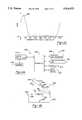
- FIG. 4Ais an electrical schematic diagram of a test kiosk according to the present invention.
- FIG. 4Bis an illustration of a coupling fixture utilized in the test kiosk of FIG. 4A;
- FIG. 5is a functional block diagram of a transmitter according to the present invention.
- FIG. 6is an illustration of a display and a functional block diagram of the central control station of FIG. 1.
- the security system including the present inventionis being described in conjunction with a transmitter carried and actuated by a person in an area under surveillance, skilled artisans will appreciate that the present invention has a much broader application.
- the security systemcan be actuated by a vehicle alarm system or by other sensors/transmitter combinations.
- a security system 10includes a central control station 14, one or more transmitters 18, one or more remote monitoring stations 22, and one or more remote sensing stations 24.
- Central control station 14includes a microprocessor 30 connected to memory 34 which includes internal and external RAM and ROM.
- Microprocessor 30 and memory 34are connected via an input/output interface 38 to a display 42, a data recorder 46 (for example a videocassette recorder, a high density digital storage for digitized video, etc.), input devices 50 (such as a mouse 50-3 (FIG. 6), a keyboard 50-1, a microphone 50-2, a joystick 50-4 preferably with zoom and focus switches, etc.), and output devices 54 (such as digital storing devices, printers, speakers 54-1 (FIG. 6), etc.).
- An audio signal processor 56 and a video signal processor 58are coupled to interface 38 or directly to microprocessor 30.
- Each sensing station 24includes an antenna system 60 for receiving radio frequency (RF) signals 62 from one or more transmitters 18.
- a receiver and data decoder 64processes RF signals 62 and transmits received and decoded data through interface 66 to central control station 14.
- Security system 10also includes one or more simulated transmitters 67 which have a fixed or predetermined location in the area under surveillance and which periodically generate RF signals to test security system 10.
- Security system 10includes multiple monitoring stations 22 which are located adjacent to or remote from one or more sensing station(s) 24.
- Security system 10includes one or more sensing stations 24 which are connected by interface 66 or by additional interfaces to interface 38. Sensing stations 24 are positioned throughout the area under surveillance. Locating monitoring stations 22 and sensing stations 24 in close proximity allows sharing of power supplies, data link connections, etc.
- Central control station 14transmits sensor control data to a camera 70, a spotlight 72, and a microphone 76, which are mounted on a positioning device 80.
- a speaker 78is preferably mounted at a location remote from positioning device 80. Alternatively, speaker 78 can be located on positioning device 80. Speaker 78 is ideally positioned such that audio signals output therefrom can be heard in the area under surveillance. Multiple speakers 78 can be provided.
- Central control station 14transmits audio data from the central station's microphone (e.g. input device 50) to the speaker 78. Audio data can also be digitized and compressed.
- Monitoring station 22transmits audio data from microphone 76 to central station's speaker (e.g. output device 54). Such audio data can include alarms, voice data from operator, etc.
- Video signals generated by camera 70are also transmitted to central station 14. Preferably video signals are compressed by camera 70 or another circuit or processor using compression techniques of the JPEG, MPEG or other types for more efficient transmission and/or storage.
- Central control station 14transmits positioning data to positioning device 80 which preferably provides both pan and tilt mobility to accurately position camera 70, spotlight 72, and microphone 76.
- Positioning datapreferably includes pan, tilt and angle commands.
- Sensor control datapreferably includes camera lens commands (such as zoom, focus and iris), and on/off commands for camera 70, spotlight 72, microphone 76 and speaker 78. Other types of positioning and control data will be readily apparent.
- Transmitter 18includes an omnidirectional antenna 84 and a transmitter actuator 88 which preferably is a button.
- transmitter actuator 88can be a voice activated switch, a car alarm sensor output, or outputs of other suitable sensors.
- Simulated transmitters 67include an actuator 90 for periodically triggering transmission of the RF signals via antenna 92.
- Actuator 90is preferably a timer.
- transmitter 67is directly wired to central station for manual or automatic actuation by a switch located at central control station 14 or includes a receiver for receiving an actuation signal from a transmitter located at central station 14, monitoring station 22 or sensing station 24. Since the time of actuation and location of simulated transmitter are known, automatic response of personal security system 10 is periodically tested and verified. A test status message, for example an icon with the word "GO" is displayed on display 42 to indicate that personal security system 10 is operating properly. Results of the test are stored in memory 34 for use in system trouble-shooting or for evidence of proper system operation.
- Interface 38 of central control station 14 and interface 66 of remote monitoring station 22is coupled using direct links or through RF or infrared (IR) links (or transceivers).
- IRinfrared
- Other linkswill be apparent to the skilled artisan.
- Such linksare preferably able to carry multimedia including voice, video and data, however separate links may be used for each type of data.
- Direct linkscan be copper cable, fiberoptic cable, and carrier current signals using existing powerlines. Fiberoptic cable carries full bandwidth video and is relatively immune to ground loops or interference which can arise if the copper cable is placed in a housing adjacent power lines.
- transmitter 18When a user triggers actuator 88, transmitter 18 generates an RF signal, using antenna 84, including an alert code followed by a continuous wave (CW) burst for a CW burst period. Transmitter 18 then generates an identification (ID) code which is unique to each transmitter associated with security system 10.
- IDidentification
- the relative order of generating the alert code, the CW burst and the ID codecan be varied. For example, the ID code and the alert code can be combined and sent prior to the CW burst. Other transmission variations will be readily apparent.
- the alert codeincludes a first pulse 7 milliseconds in duration. Subsequently, at 4 millisecond intervals, alternating ones and zeros are transmitted. A zero is a pulse 300 microseconds in duration and a one is a pulse 600 microseconds in duration.
- the transmitter 18transmits the CW burst for preferably 30 to 150 milliseconds after which the identification code is transmitted. The transmitter 18 can repeat the alert code, the CW burst, and the identification code one or more times immediately or periodically. Other data may also be transmitted to convey specific requests or commands.
- a system clock 100provides timing and is connected to a divider chain 104 which steps down the output frequency of system clock 100 as desired.
- One output of system clock 100is connected to an antenna drive circuit 108 which drives antenna system 60.
- FM signals received by antenna system 60are input to a frequency modulated (FM) receiver 114 which demodulates the RF signals.
- FM receiver 114outputs a demodulated audio output signal to an angle processor 118 which receives timing signals from a second output of divider chain 104.
- Antenna system 60operates using Doppler direction finding (DF) techniques in -which a rotating receiving antenna is created electronically.
- Electronic rotation of antenna system 60frequency modulates a received RF signal from transmitter 18 with a modulation phase dependent on the position of the actuated transmitter 18 relative to the antenna system 60.
- DF angle processor 118filters the audio signal output by FM receiver 114, improves the signal to noise (S/N) ratio of the audio output signal, and compares the phase of the audio output signal to the phase of the antenna drive signal. The phase difference is related to the angular position of transmitter 18 generating the RF signal relative to the reference direction of the antenna drive signal of the antenna system 60.
- Sensing station 24determines the relative position of the actuated transmitter 18 during a portion of the CW burst period, e.g. after the CW burst begins and before the CW burst ends.
- FM receiver 114outputs a signal strength output signal (preferably on a logarithmic scale) to a multipath editor processor 122 and to a clip/clamp circuit 126. FM receiver 114 also outputs an unmuted audio output to multipath editor processor 122. Multipath cancellation of the direct path and the ground reflected path is sensed by multipath editor 122 as signal level degradation increases. Multipath editor 122 inhibits angle output to prevent reflections, with large azimuth errors, from dominating the composite signal. To provide inhibit control during the low level signal, an output of multipath editor processor 122 is connected to one input of a NAND gate 128. An output of NAND gate 128 is connected to an enable gate (with low enable logic) of FM receiver 114.
- multipath editor processor 122is shown in FIG. 2 as forming part of direction finding unit 24, signal inputs to multipath editor processor 122 may be routed to central control station 14 and multipath editor processor 122 can be associated therewith. If multipath processing is performed at central control station 14, more elaborate algorithms can be employed using input signals from multiple direction finding units 24 receiving the transmitter signal.
- a clipped and clamped output signalis input to a code recognizer circuit 130.
- code recognizer circuit 130recognizes the alert code
- code recognizer 130outputs an enable signal to a second input gate of NAND gate 128 which enables FM audio output generated from antenna system 60 to angle processor 118 for a CW sampling period.
- angle processor 118is enabled during the CW sampling period and not during the alert or ID codes to prevent spurious position (i.e. angle data) determinations.
- Angle processor 118generates a digital angle value related to the angle of transmitter 18 relative to the position of antenna system 60. After the CW sampling period, code recognizer 130 disables NAND gate 128.
- the triggering of NAND gate 128, as described above,enables receiver, data decoder, and angle processor 64 to perform DF functions after receipt of the alert code and after initiation of the CW burst.
- the NAND gate 128is disabled before the CW burst period ends (e.g. the CW burst period>the CW sampling period). By gating NAND gate 128 in this manner, false DF readings due to random noise can be reduced and degradation of the DF angle measurement due to turn-on and turn-off FM transients of the transmitter waveform is avoided.
- a formatting and multiplexing circuit 144connected to angle processor 118 and holding register 140, combines the ID code and the digital angle value into an alert data word transmitted by a link modulator 148 via interfaces 66 and 38 to microprocessor 30 at central station 14.
- Central control station 14responds to the alert data word, sent by one or more direction finding units 24, by localizing and orienting the transmitter 18 on a map display (described below in conjunction with FIG. 6). Central control station 14 computes direction control signals for transmission to positioning device 80, and enable signals for camera 68, spotlight 72, microphone 76 (if camera 68, spotlight 72 and microphone 76 are not operating in a manual override or automatic actuation already). While only one remote monitoring device 22 is illustrated in FIG. 1 and described herein, one can appreciate that additional monitoring devices can be provided and controlled in a similar manner. The direction control signals instruct positioning device 80 to direct camera 68, microphone 76, and spotlight 72 towards transmitter 18 which generated the detected RF signals.
- a currently preferred antenna system 60includes eight variable attenuators 161-168 connected to eight circularly polarized (CP) helical antenna elements 171-178 respectively.
- CPcircularly polarized
- Suitable helical antennasare disclosed in C. C. Kilgas, “Multielement, Fractional Turn Helices,” IEEE Transactions on Antennas and Propagation, July 1968, hereby incorporated by reference.
- the helical antennasare bifilar.
- Variable attenuators 161-168are programmed by attenuator drive circuit 179 as a function of time, each with the same profile but staggered in time relative to a desired sweep angle of the antenna system 60 to simulate a smooth and continuous rotation from one antenna element to the next, and to reduce the harmonics in the antenna modulation.
- Outputs of dipole antenna elements 171-178are combined in a conventional manner and fed to FM receiver 114.
- Antenna system 60electronically simulates a physically rotating antenna.
- a DF antenna system employing variable attenuatorsis disclosed in Cunningham U.S. Pat. No. 4,551,727, hereby incorporated by reference. Additional or fewer variable attenuator/dipole antenna pairs can be provided. Additional variable attenuator/dipole antenna pairs can decrease multipath effects. Other methods of providing physically or electronically rotating antenna systems are contemplated and will be apparent to skilled artisans.
- helical antenna elements 171-178are shown mounted in a circle on a stripline circuit board 182. Attenuators 161-168 and baluns are fabricated on stripline circuit board 182.
- helical antenna elements 171-178are constructed of glass fiber cylinders with a helix-shaped conductor printed on an inside surface thereof. The glass fiber cylinders weatherproof the helical antenna elements.
- the aximuth patternis preferably constant relative to varying azimuth angles. The polarization observed from any azimuth angle is circular.
- variable attenuator 171varies the gain of the corresponding CP helical antenna element 161 as shown.
- Each of the gains for the other helical antennas 162-168are similarly varied, however, a peak 190 of the gain response is shifted 45°, 90°, 135°, 180°, 225°, 270° and 315° for other antenna element/variable attenuator pairs.
- the gain for one antennadecreases to approximately one half of maximum (decreasing) when the gain for the adjacent antenna (45° phase shifted) is one half of maximum (increasing).
- a test kiosk 200includes an antenna 203, receiver and decoder 204, an input/output interface 208, a microprocessor 212, memory 214 which can include internal and external RAM and ROM, a display 218, a keyboard or other input device (such as a touch screen, mouse, etc.) 220, and a communications link 222.
- test kiosk 200includes a coupling fixture 230 which engages and orients a transmitter 18 to be tested at a standard distance and orientation with respect to antenna 203 which is connected to a receiver and decoder 204.
- Coupling fixture 230includes a lid 234 defining a first mating recess 236 and a base 237 defining a second mating recess 238.
- First and second mating recesses 236 and 238mate with outer surfaces of transmitter 18 when transmitter 18 is inserted (in the direction indicated by arrows "A") to accurately position transmitter 18.
- First mating recess 236may include an actuator recess 240 to receive actuator 88 of transmitter 18 when lid 234 is in the closed position.
- Coupling fixturefurther includes a microswitch 250 and a solenoid 252 which can be connected via interface 208 to microprocessor 212.
- microswitch 250When microswitch 250 generates a signal indicating that lid 234 is fully closed, microprocessor 212 actuates solenoid 252 (immediately or after a timed period) which depresses button 88 and triggers transmitter 18.
- RF signals generated by transmitter 18are received by antenna 203. While additional components of test kiosk 200 shown in FIG. 4A are omitted from FIG. 4B, skilled artisan can appreciate that these components can be located in, nearby, or remote from test kiosk 200.
- a conventional latch mechanism 260can be provided to lock lid 234 in the closed position.
- Coupling fixture 202is designed such that transmitter 18 can be inserted in only one way. Coupling fixture 202 will close only if transmitter 18 is positioned correctly. Actuator 88, preferably a button, on transmitter 18 is depressed by coupling fixture 202 automatically to avoid effects of human proximity and to improve consistency and repeatability of the test.
- microprocessor 212executes an operating program, located in memory 214, which instructs a user via display 218 to place a transmitter 18 to be tested in coupling fixture 202.
- microprocessor 212generates step-by-step user instructions on display 218 in a conventional manner.
- Microprocessor 212requests a user's name or other identification via display 218 and requests that the user type in responses using input device 220.
- Microprocessor 212then provides instructions for inserting transmitter 18 into coupling fixture 202.
- a userplaces the transmitter 18 in coupling fixture 202 which positions transmitter 18 at a predetermined distance from a receiver and decoder 204.
- Coupling fixture 202automatically triggers actuator 88 when lid 234 is closed.
- Receiver and decoder 204determines the power output level of transmitter 18 which is related to battery charge level. Coupling fixture 202 ensures that power output level measurements are consistently made by positioning the transmitters 18 to be tested in a standard position with respect to receiver and decoder 204. Receiver and decoder 204 receives and decodes the alert code, the CW burst, and the ID code. Microprocessor 212 verifies the ID code using the user's name or other identification previously entered using input device 220 and verifies the alert code.
- Microprocessor 212stores the ID code, the date, the time, and the transmitter signal output level (which is related to battery strength) in memory 214.
- Test kiosk 200includes a communications link 222 providing a data connection to central station 14. Communications link 222 can be a modem, RF link, etc.
- Memory 34 of central station 14 or memory 214 of test kiosk 200preferably also includes battery replacement records which can be used to generate battery replacement reminders to users based upon the expected life of the transmitter's batteries.
- transmitter 300is shown in greater detail and includes an input/output interface 302, a microprocessor 306, memory 310, an actuator 314 (for example, a button or a timer), an oscillator 318, and an antenna 322.
- the alert and ID codesare stored in memory 310.
- An input device 326which is connected to interface 302 inputs the alert and ID codes. Operating code for microprocessor 306 is also input via input device 326.
- Transmitters similar to transmitters 18, 67 and 300 according to the inventionare disclosed in U.S. Pat. No. 4,881,148 which is entitled “Remote Control System for Door Locks", which issued Nov. 14, 1989 to Lambropoulos et al. and which is hereby incorporated by reference. Transmitters disclosed therein output several initialization bits, an ID code, and a function code in contrast to the CW burst, and the alert and ID codes of the present invention. However, modifying such a transmitter to provide such operation will be apparent.
- Display 42includes a map window 350 which displays the relative position of an actuated transmitter 354 within the area under surveillance. Relative positions of sensing stations 358-1, 358-2, . . . , and 358-9 and monitoring stations 360-1 and 360-2 are preferably also shown. Icons are preferably used to depict transmitter 354, monitoring stations 360, sensing stations 358, etc. in a conventional manner. A grid 362 is preferably defined in map window 350 to allow easier identification of the location of the actuated transmitter 354.
- a horizontal side of map window 350is assigned fixed-size grids A-Z from left to right.
- a vertical side of map windowis assigned fixed sized grids 1-26.
- transmitter 354could be located in grid G7.
- conventional pull-down menusare used to select control options.
- a camera centerline 363-1 and an ellipse 364-1are provided on map view 350 to illustrates the centerline and field of view (FOV) of camera 360-1 so that camera 360-1 is accurately positioned.
- a camera centerline 363-2 and an ellipse 364-2are provided on map view 350 to illustrates the centerline and field of view (FOV) of camera 360-2 so that camera 360-2 is accurately positioned.
- Colored shadingis preferably used to differentiate FOV 364-1 from 364-2.
- Display 42includes a status screen 369 for displaying on/off status of microphone 76, camera 70, speaker 78, spotlight 72, etc. and the status of the self-test function of security system 10 (described above in conjunction with simulated transmitters 67).
- Display 42preferably includes a video window 370 in which video signals from an area surrounding the actuated transmitter 354 are displayed.
- a video window 370in which video signals from an area surrounding the actuated transmitter 354 are displayed.
- multiple different scenes or views of the same scenecan be simultaneously displayed by splitting video window 370.
- map window 350simultaneously displays different areas under surveillance by splitting window 350 or multiple actuated transmitters in the same area under surveillance are shown.
- Video signal processor 58is used to isolate and select particular frames of interest for further use in identifying a suspect, a vehicle, etc.
- the selected framesare compared and correlated with criminal files to generate identities of suspects. Dithering, or jumping between multiple frames, and frame averaging are used to improve image analysis. Motion compensation can also be used.
- the selected framescan be used to identify a license plate of a getaway vehicle.
- Video signal processor 58also provides motion sensing functions to track movement, for example to track the suspect and the transmitter user. This involves frame to frame processing where the position of images in successive frames are compared and contrasted with fixed background.
- Video signal processor 58can provide motion sensing functions to track movement, for example movement of a suspect and a transmitter user.
- Video signal processor 58can track movement by subtracting successive video frames.
- Video signal processor 58generates a control signal to move the camera FOV and pixels having significant differences in the camera FOV.
- Audio signal processor 56analyzes, compares, and correlates voice samples collected using microphone 76. The voice samples can be compared and correlated with a voice sample of a suspect as further identification evidence. Suitable audio signal processing techniques are disclosed in L. R. Rabiner, "Applications of Voice Processing to Telecommunications" IEEE Proceedings, Vol. 82, No 2 (Feb. 1994). Audio signal processor 56 can perform audio processing using sonogram (frequency vs. time) comparisons, time and frequency warping, amptitude comparisons, and pattern matching.
- the area under surveillancecan be a parking garage, an outdoor parking lot, shopping malls or other, preferably open, indoor and outdoor areas.
- FM receiver 114can be a SA625 receiver sold by Phillips.
- Camera 70can be a high resolution color camera.
- Camera 70can be a charge coupled device (CCD) camera which generates analog or digital video signals and can operate at visible or infrared wavelengths. If infrared wavelengths are used, spotlight 72 also preferably operates at infrared wavelengths.
- Camera 70can have automatic iris control with manual override capability.
- Microphone 76is preferably a directional microphone.
- a userIn use, a user carries a transmitter 18 when entering the area under surveillance. Referring to FIG. 1, if the user encounters trouble, the user triggers actuator 88. Transmitter 18 generates an RF signal including the alert code, the CW burst for the CW period, and the identification code which uniquely identifies the user. One or more sensing stations 24 receive the RF signal from the transmitter 18.
- antenna system 60 and receiver and decoder 64 of each sensing station 24 receiving the RF signaldecode the alert code, perform direction finding processing on the CW burst and decode the identification code.
- Each receiver and decoder 64transmits the identification code and angle data to central station 14.
- Central station 14analyzes the identification codes and angles from each sensing station 24 and selects at least one monitoring station 22 for surveillance. Central control station 14 uses triangulation (using data from at least two sensing stations 24) to determine the angle and distance to the actuated transmitter in relation to the selected monitoring station 22. Triangulation is described in detail in U.S. Pat. No. 4,954,836, entitled “Follow-Up System for Moving Bodies", which issued to Sakuma and is hereby incorporated by reference.
- Central control station 14transmits control data, position data and audio data to at least one selected monitoring station 22.
- Positioning device 80 of the selected monitoring station 22receives the position data from central station 14 and directs the camera 70, spotlight 72 and microphone 76 towards the user.
- Monitoring station 22transmits video signals generated by camera 70 and audio signals generated .by microphone 76 to central station 14.
- central station 14displays the location of the actuated transmitter relative to map window 350 and video signals in video window 370.
- An operatorturns spotlight 72 on to scare off a suspect and to provide more light for camera 70.
- the operatortalks and listens to the user and the suspect using the microphone 50-2 and the speaker 54-1 associated with central station 14 and one or more monitoring stations 22.
- Joystick 50-4 or other devicesare used to redirect the camera 70.
- mouse 50-3is used to select and drag (in a conventional manner) the ellipse 364 to a desired position.
- Central control station 14responds to the changes by sending updated position data to the monitoring station(s) 22.
- the number of monitoring stations 22 and sensing stations 24 required for an area under surveillancewill vary according to the size of the area under surveillance, the coverage desired, the resolution and FOVs of the camera chosen, the number of concurrent emergencies to be handled in the area under surveillance, etc.
- video window 370 in display 42 of FIG. 6can be divided to accommodate multiple video scenes corresponding to concurrent emergencies. Additional displays may also be associated with central control station 14.
- personal security systems 10allows quick response to an emergency situation.
- the personal security system 10locates the actuated transmitter 18 and provides video, two-way audio and spotlight illumination.
- Such an immediate responsemay be sufficient to startle the suspect causing the suspect to flee.
- the operatorcan audibly indicate that the suspect is being recorded on video and that police or security personnel are on the way.
- Determining the identity of the suspectcan be aided through voice samples and multiple video views using one or more cameras.
- the personal security system 10also helps identify the color, make and model of the suspect's vehicle or the type and color of the suspect's clothing.
- the videomay provide effective evidence of elements of a crime for trial. Once activated, the transmitter need not be actuated again which can often be difficult in emergency and panic situations.
- test kiosk 200and simulated transmitters 67 ensure proper operation of personal security system 10 and transmitters 18. Automatic periodic operation of transmitters 67 is synchronized with a system test of system elements. System status, determined by the system test, is stored for evidence of proper or improper system operation. Test kiosk 200 records operational performance of a particular transmitter 18 over time.
Landscapes
- Engineering & Computer Science (AREA)
- Human Computer Interaction (AREA)
- Physics & Mathematics (AREA)
- General Physics & Mathematics (AREA)
- Computer Networks & Wireless Communication (AREA)
- Alarm Systems (AREA)
Abstract
Description
Claims (41)
Priority Applications (1)
| Application Number | Priority Date | Filing Date | Title |
|---|---|---|---|
| US08/279,760US5546072A (en) | 1994-07-22 | 1994-07-22 | Alert locator |
Applications Claiming Priority (1)
| Application Number | Priority Date | Filing Date | Title |
|---|---|---|---|
| US08/279,760US5546072A (en) | 1994-07-22 | 1994-07-22 | Alert locator |
Publications (1)
| Publication Number | Publication Date |
|---|---|
| US5546072Atrue US5546072A (en) | 1996-08-13 |
Family
ID=23070333
Family Applications (1)
| Application Number | Title | Priority Date | Filing Date |
|---|---|---|---|
| US08/279,760Expired - LifetimeUS5546072A (en) | 1994-07-22 | 1994-07-22 | Alert locator |
Country Status (1)
| Country | Link |
|---|---|
| US (1) | US5546072A (en) |
Cited By (150)
| Publication number | Priority date | Publication date | Assignee | Title |
|---|---|---|---|---|
| WO1997019558A1 (en)* | 1995-11-22 | 1997-05-29 | Sensormatic Electronics Corporation | Video surveillance apparatus and system |
| US5666157A (en)* | 1995-01-03 | 1997-09-09 | Arc Incorporated | Abnormality detection and surveillance system |
| US5696705A (en)* | 1995-08-29 | 1997-12-09 | Laser Technology, Inc. | System and method for reconstruction of the position of objects utilizing a signal transmitting and receiving distance determining device |
| US5793419A (en)* | 1994-10-14 | 1998-08-11 | Systems Engineering & Management Co., Inc. | Personal audio/video surveillance system |
| US5818733A (en)* | 1994-07-01 | 1998-10-06 | Hyuga; Makoto | Communication method and system for same |
| US5938706A (en)* | 1996-07-08 | 1999-08-17 | Feldman; Yasha I. | Multi element security system |
| US6028627A (en)* | 1997-06-04 | 2000-02-22 | Helmsderfer; John A. | Camera system for capturing a sporting activity from the perspective of the participant |
| US6052052A (en)* | 1997-08-29 | 2000-04-18 | Navarro Group Limited, Inc. | Portable alarm system |
| US6052051A (en)* | 1999-02-23 | 2000-04-18 | Whalen; Patrick J. | Multilocation defense device |
| US6215404B1 (en)* | 1999-03-24 | 2001-04-10 | Fernando Morales | Network audio-link fire alarm monitoring system and method |
| US20010010541A1 (en)* | 1998-03-19 | 2001-08-02 | Fernandez Dennis Sunga | Integrated network for monitoring remote objects |
| US6278884B1 (en)* | 1997-03-07 | 2001-08-21 | Ki Il Kim | Portable information communication device |
| US6288641B1 (en)* | 1999-09-15 | 2001-09-11 | Nokia Corporation | Assembly, and associated method, for remotely monitoring a surveillance area |
| US6317039B1 (en)* | 1998-10-19 | 2001-11-13 | John A. Thomason | Wireless video audio data remote system |
| US6433683B1 (en)* | 2000-02-28 | 2002-08-13 | Carl Robinson | Multipurpose wireless video alarm device and system |
| US20020137501A1 (en)* | 2001-03-23 | 2002-09-26 | Rajendra Datar | Systems and methods for wireless memory programming |
| US6466258B1 (en) | 1999-02-12 | 2002-10-15 | Lockheed Martin Corporation | 911 real time information communication |
| US20030009329A1 (en)* | 2001-07-07 | 2003-01-09 | Volker Stahl | Directionally sensitive audio pickup system with display of pickup area and/or interference source |
| US6525663B2 (en)* | 2001-03-15 | 2003-02-25 | Koninklijke Philips Electronics N.V. | Automatic system for monitoring persons entering and leaving changing room |
| US20030052970A1 (en)* | 2001-09-19 | 2003-03-20 | Dodds G. Alfred | Automatically activated wireless microphone for in-car video system |
| US20030081122A1 (en)* | 2001-10-30 | 2003-05-01 | Kirmuss Charles Bruno | Transmitter-based mobile video locating |
| US6559769B2 (en) | 2001-10-01 | 2003-05-06 | Eric Anthony | Early warning real-time security system |
| US6563416B1 (en)* | 1998-12-11 | 2003-05-13 | Mannesmann Vdo Ag | Locking device for a motor vehicle having a number of doors |
| US20030104806A1 (en)* | 2001-12-05 | 2003-06-05 | Wireless Peripherals, Inc. | Wireless telepresence collaboration system |
| US6597389B2 (en)* | 1996-01-30 | 2003-07-22 | Canon Kabushiki Kaisha | Camera control system and camera control apparatus |
| US20030164877A1 (en)* | 2000-06-30 | 2003-09-04 | Nobuo Murai | Remote monitoring method and monitor control server |
| US6693534B2 (en)* | 2001-09-24 | 2004-02-17 | Spx Corporation | Emergency alarm system using pull-station with camera |
| US20040066282A1 (en)* | 2001-09-24 | 2004-04-08 | Costa Hilario S. | Alarm pull-station with camera |
| US20040087314A1 (en)* | 2002-11-06 | 2004-05-06 | Charles Duncan | Apparatus and method for tracking the location and position of an individual |
| US20040132461A1 (en)* | 2002-11-06 | 2004-07-08 | Charles Duncan | Apparatus and method for tracking the location and position of an individual using an accelerometer |
| US6768975B1 (en)* | 1996-11-29 | 2004-07-27 | Diebold, Incorporated | Method for simulating operation of an automated banking machine system |
| US20040150718A1 (en)* | 2003-01-30 | 2004-08-05 | Jian Zhang | Method for the real-time monitoring and transmission of a visual domestic safeguard system |
| US20040207728A1 (en)* | 2003-02-05 | 2004-10-21 | Matsushita Electric Industrial Co., Ltd. | Image server and an image server system |
| US20040207523A1 (en)* | 2003-04-18 | 2004-10-21 | Sa Corporation, A Texas Corporation | Integrated campus monitoring and response system |
| US20050057361A1 (en)* | 2003-07-10 | 2005-03-17 | University Of Florida Research Foundation, Inc. | Remote surveillance and assisted care using a mobile communication device |
| US6873256B2 (en) | 2002-06-21 | 2005-03-29 | Dorothy Lemelson | Intelligent building alarm |
| US20050144296A1 (en)* | 2000-11-17 | 2005-06-30 | Monroe David A. | Method and apparatus for distributing digitized streaming video over a network |
| US20050174229A1 (en)* | 2004-02-06 | 2005-08-11 | Feldkamp Gregory E. | Security system configured to provide video and/or audio information to public or private safety personnel at a call center or other fixed or mobile emergency assistance unit |
| US20050201826A1 (en)* | 2004-03-15 | 2005-09-15 | Zhang Jack K. | Methods and systems for mapping locations of wireless transmitters for use in gathering market research data |
| US20050203798A1 (en)* | 2004-03-15 | 2005-09-15 | Jensen James M. | Methods and systems for gathering market research data |
| US20050220310A1 (en)* | 2004-03-30 | 2005-10-06 | Mcgrath William R | Technique and device for through-the-wall audio surveillance |
| US20050245195A1 (en)* | 2000-06-03 | 2005-11-03 | Ebox Usa Inc. | Computerized recording and notification of the delivery and pickup of retail goods |
| US20060114326A1 (en)* | 2000-05-19 | 2006-06-01 | Koichiro Tanaka | Image display apparatus, image display system, and image display method |
| US20060192659A1 (en)* | 2005-02-15 | 2006-08-31 | Fazio Michele P | Spy guard system, photo vision and/or message notification system |
| US20070090948A1 (en)* | 2002-08-12 | 2007-04-26 | Sobol Raymond J | Portable Instantaneous Wireless Event Based Photo Identification and Alerting Security System |
| US20070140487A1 (en)* | 2005-12-19 | 2007-06-21 | Nortel Networks Limited | Method and apparatus for secure transport and storage of surveillance video |
| US7321783B2 (en) | 1997-04-25 | 2008-01-22 | Minerva Industries, Inc. | Mobile entertainment and communication device |
| US7366646B1 (en) | 1996-11-29 | 2008-04-29 | Diebold, Incorporated | Fault monitoring and notification system for automated banking machines |
| US7383019B1 (en)* | 2004-10-15 | 2008-06-03 | The United States Of America As Represented By The Secretary Of The Navy | Field data collection and relay station |
| US20080171510A1 (en)* | 2007-01-16 | 2008-07-17 | Seiko Epson Corporation | Positioning device, electronic instrument, and filter passband changing method |
| US20090033736A1 (en)* | 2007-08-01 | 2009-02-05 | John Thomason | Wireless Video Audio Data Remote System |
| US20090041228A1 (en)* | 2000-04-17 | 2009-02-12 | Michael Kevin Owens | Remote battery replacement notification system and method |
| US7504965B1 (en) | 2005-08-05 | 2009-03-17 | Elsag North America, Llc | Portable covert license plate reader |
| US20100130144A1 (en)* | 2008-11-24 | 2010-05-27 | Qualcomm Incorporated | Techniques for improving transmitter performance |
| US20110069168A1 (en)* | 2009-09-23 | 2011-03-24 | Chia-Chun Tsou | Vehicle surveillance system for use in parking lots |
| US20110102587A1 (en)* | 2009-11-02 | 2011-05-05 | Michael Zittel | Spotlight with security camera |
| US20110148662A1 (en)* | 2009-12-18 | 2011-06-23 | Daniel Lowenthal | System and method for notification of parking-related information |
| USRE42690E1 (en) | 1995-01-03 | 2011-09-13 | Prophet Productions, Llc | Abnormality detection and surveillance system |
| ITBO20130175A1 (en)* | 2013-04-17 | 2014-10-18 | Rossi Elettronica Impianti S R L | SYSTEM AND METHOD OF SECURITY AND PROTECTION OF ONE OR MORE PEOPLE. |
| US9202363B1 (en)* | 2014-03-04 | 2015-12-01 | State Farm Mutual Automobile Insurance Company | Audio monitoring and sound identification process for remote alarms |
| US20160274759A1 (en) | 2008-08-25 | 2016-09-22 | Paul J. Dawes | Security system with networked touchscreen and gateway |
| US20170160137A1 (en)* | 2015-12-04 | 2017-06-08 | BOT Home Automation, Inc. | Motion detection for a/v recording and communication devices |
| US20170162225A1 (en)* | 2015-12-04 | 2017-06-08 | BOT Home Automation, Inc. | Motion detection for a/v recording and communication devices |
| US10051078B2 (en) | 2007-06-12 | 2018-08-14 | Icontrol Networks, Inc. | WiFi-to-serial encapsulation in systems |
| US10062273B2 (en) | 2010-09-28 | 2018-08-28 | Icontrol Networks, Inc. | Integrated security system with parallel processing architecture |
| US10062245B2 (en) | 2005-03-16 | 2018-08-28 | Icontrol Networks, Inc. | Cross-client sensor user interface in an integrated security network |
| US10079839B1 (en) | 2007-06-12 | 2018-09-18 | Icontrol Networks, Inc. | Activation of gateway device |
| US10078958B2 (en) | 2010-12-17 | 2018-09-18 | Icontrol Networks, Inc. | Method and system for logging security event data |
| US10091014B2 (en) | 2005-03-16 | 2018-10-02 | Icontrol Networks, Inc. | Integrated security network with security alarm signaling system |
| US10127801B2 (en) | 2005-03-16 | 2018-11-13 | Icontrol Networks, Inc. | Integrated security system with parallel processing architecture |
| US10142166B2 (en) | 2004-03-16 | 2018-11-27 | Icontrol Networks, Inc. | Takeover of security network |
| US10140840B2 (en) | 2007-04-23 | 2018-11-27 | Icontrol Networks, Inc. | Method and system for providing alternate network access |
| US10142394B2 (en) | 2007-06-12 | 2018-11-27 | Icontrol Networks, Inc. | Generating risk profile using data of home monitoring and security system |
| US10142392B2 (en) | 2007-01-24 | 2018-11-27 | Icontrol Networks, Inc. | Methods and systems for improved system performance |
| US10156959B2 (en) | 2005-03-16 | 2018-12-18 | Icontrol Networks, Inc. | Cross-client sensor user interface in an integrated security network |
| US10156831B2 (en) | 2004-03-16 | 2018-12-18 | Icontrol Networks, Inc. | Automation system with mobile interface |
| US10200504B2 (en) | 2007-06-12 | 2019-02-05 | Icontrol Networks, Inc. | Communication protocols over internet protocol (IP) networks |
| US20190057600A1 (en)* | 2017-08-17 | 2019-02-21 | Panasonic Intellectual Property Management Co., Ltd. | Investigation assist device, investigation assist method and investigation assist system |
| US10237237B2 (en) | 2007-06-12 | 2019-03-19 | Icontrol Networks, Inc. | Communication protocols in integrated systems |
| US10237806B2 (en) | 2009-04-30 | 2019-03-19 | Icontrol Networks, Inc. | Activation of a home automation controller |
| US10313303B2 (en) | 2007-06-12 | 2019-06-04 | Icontrol Networks, Inc. | Forming a security network including integrated security system components and network devices |
| US10339791B2 (en) | 2007-06-12 | 2019-07-02 | Icontrol Networks, Inc. | Security network integrated with premise security system |
| US10348575B2 (en) | 2013-06-27 | 2019-07-09 | Icontrol Networks, Inc. | Control system user interface |
| US10365810B2 (en) | 2007-06-12 | 2019-07-30 | Icontrol Networks, Inc. | Control system user interface |
| US10380871B2 (en) | 2005-03-16 | 2019-08-13 | Icontrol Networks, Inc. | Control system user interface |
| US10382452B1 (en) | 2007-06-12 | 2019-08-13 | Icontrol Networks, Inc. | Communication protocols in integrated systems |
| US10389736B2 (en) | 2007-06-12 | 2019-08-20 | Icontrol Networks, Inc. | Communication protocols in integrated systems |
| US10423309B2 (en) | 2007-06-12 | 2019-09-24 | Icontrol Networks, Inc. | Device integration framework |
| US10498830B2 (en) | 2007-06-12 | 2019-12-03 | Icontrol Networks, Inc. | Wi-Fi-to-serial encapsulation in systems |
| US10522026B2 (en) | 2008-08-11 | 2019-12-31 | Icontrol Networks, Inc. | Automation system user interface with three-dimensional display |
| US10523689B2 (en) | 2007-06-12 | 2019-12-31 | Icontrol Networks, Inc. | Communication protocols over internet protocol (IP) networks |
| US10530839B2 (en) | 2008-08-11 | 2020-01-07 | Icontrol Networks, Inc. | Integrated cloud system with lightweight gateway for premises automation |
| US10559193B2 (en) | 2002-02-01 | 2020-02-11 | Comcast Cable Communications, Llc | Premises management systems |
| US10616075B2 (en) | 2007-06-12 | 2020-04-07 | Icontrol Networks, Inc. | Communication protocols in integrated systems |
| US10637575B2 (en) | 2016-05-25 | 2020-04-28 | Wisconsin Alumni Research Foundation | Spatial location indoors using standard fluorescent fixtures |
| US10666523B2 (en) | 2007-06-12 | 2020-05-26 | Icontrol Networks, Inc. | Communication protocols in integrated systems |
| US10721087B2 (en) | 2005-03-16 | 2020-07-21 | Icontrol Networks, Inc. | Method for networked touchscreen with integrated interfaces |
| US10747216B2 (en) | 2007-02-28 | 2020-08-18 | Icontrol Networks, Inc. | Method and system for communicating with and controlling an alarm system from a remote server |
| US10785319B2 (en) | 2006-06-12 | 2020-09-22 | Icontrol Networks, Inc. | IP device discovery systems and methods |
| US10841381B2 (en) | 2005-03-16 | 2020-11-17 | Icontrol Networks, Inc. | Security system with networked touchscreen |
| US10979389B2 (en) | 2004-03-16 | 2021-04-13 | Icontrol Networks, Inc. | Premises management configuration and control |
| US10999254B2 (en) | 2005-03-16 | 2021-05-04 | Icontrol Networks, Inc. | System for data routing in networks |
| US11089122B2 (en) | 2007-06-12 | 2021-08-10 | Icontrol Networks, Inc. | Controlling data routing among networks |
| US11113950B2 (en) | 2005-03-16 | 2021-09-07 | Icontrol Networks, Inc. | Gateway integrated with premises security system |
| US11146637B2 (en) | 2014-03-03 | 2021-10-12 | Icontrol Networks, Inc. | Media content management |
| US11153266B2 (en) | 2004-03-16 | 2021-10-19 | Icontrol Networks, Inc. | Gateway registry methods and systems |
| US11182060B2 (en) | 2004-03-16 | 2021-11-23 | Icontrol Networks, Inc. | Networked touchscreen with integrated interfaces |
| US11201755B2 (en) | 2004-03-16 | 2021-12-14 | Icontrol Networks, Inc. | Premises system management using status signal |
| US11212192B2 (en) | 2007-06-12 | 2021-12-28 | Icontrol Networks, Inc. | Communication protocols in integrated systems |
| US11218878B2 (en) | 2007-06-12 | 2022-01-04 | Icontrol Networks, Inc. | Communication protocols in integrated systems |
| US11237714B2 (en) | 2007-06-12 | 2022-02-01 | Control Networks, Inc. | Control system user interface |
| US11240059B2 (en) | 2010-12-20 | 2022-02-01 | Icontrol Networks, Inc. | Defining and implementing sensor triggered response rules |
| US11244545B2 (en) | 2004-03-16 | 2022-02-08 | Icontrol Networks, Inc. | Cross-client sensor user interface in an integrated security network |
| US11258625B2 (en) | 2008-08-11 | 2022-02-22 | Icontrol Networks, Inc. | Mobile premises automation platform |
| US11277465B2 (en) | 2004-03-16 | 2022-03-15 | Icontrol Networks, Inc. | Generating risk profile using data of home monitoring and security system |
| US11310199B2 (en) | 2004-03-16 | 2022-04-19 | Icontrol Networks, Inc. | Premises management configuration and control |
| US11316958B2 (en) | 2008-08-11 | 2022-04-26 | Icontrol Networks, Inc. | Virtual device systems and methods |
| US11316753B2 (en) | 2007-06-12 | 2022-04-26 | Icontrol Networks, Inc. | Communication protocols in integrated systems |
| US11343380B2 (en) | 2004-03-16 | 2022-05-24 | Icontrol Networks, Inc. | Premises system automation |
| US11368327B2 (en) | 2008-08-11 | 2022-06-21 | Icontrol Networks, Inc. | Integrated cloud system for premises automation |
| US11398147B2 (en) | 2010-09-28 | 2022-07-26 | Icontrol Networks, Inc. | Method, system and apparatus for automated reporting of account and sensor zone information to a central station |
| US11405463B2 (en) | 2014-03-03 | 2022-08-02 | Icontrol Networks, Inc. | Media content management |
| US11424980B2 (en) | 2005-03-16 | 2022-08-23 | Icontrol Networks, Inc. | Forming a security network including integrated security system components |
| US11423756B2 (en) | 2007-06-12 | 2022-08-23 | Icontrol Networks, Inc. | Communication protocols in integrated systems |
| US11451409B2 (en) | 2005-03-16 | 2022-09-20 | Icontrol Networks, Inc. | Security network integrating security system and network devices |
| US11489812B2 (en) | 2004-03-16 | 2022-11-01 | Icontrol Networks, Inc. | Forming a security network including integrated security system components and network devices |
| US11496568B2 (en) | 2005-03-16 | 2022-11-08 | Icontrol Networks, Inc. | Security system with networked touchscreen |
| US11582065B2 (en) | 2007-06-12 | 2023-02-14 | Icontrol Networks, Inc. | Systems and methods for device communication |
| US11601810B2 (en) | 2007-06-12 | 2023-03-07 | Icontrol Networks, Inc. | Communication protocols in integrated systems |
| US11615697B2 (en) | 2005-03-16 | 2023-03-28 | Icontrol Networks, Inc. | Premise management systems and methods |
| US11646907B2 (en) | 2007-06-12 | 2023-05-09 | Icontrol Networks, Inc. | Communication protocols in integrated systems |
| US11677577B2 (en) | 2004-03-16 | 2023-06-13 | Icontrol Networks, Inc. | Premises system management using status signal |
| US11700142B2 (en) | 2005-03-16 | 2023-07-11 | Icontrol Networks, Inc. | Security network integrating security system and network devices |
| US11706045B2 (en) | 2005-03-16 | 2023-07-18 | Icontrol Networks, Inc. | Modular electronic display platform |
| US11706279B2 (en) | 2007-01-24 | 2023-07-18 | Icontrol Networks, Inc. | Methods and systems for data communication |
| US11729255B2 (en) | 2008-08-11 | 2023-08-15 | Icontrol Networks, Inc. | Integrated cloud system with lightweight gateway for premises automation |
| US11750414B2 (en) | 2010-12-16 | 2023-09-05 | Icontrol Networks, Inc. | Bidirectional security sensor communication for a premises security system |
| US11758026B2 (en) | 2008-08-11 | 2023-09-12 | Icontrol Networks, Inc. | Virtual device systems and methods |
| US11792330B2 (en) | 2005-03-16 | 2023-10-17 | Icontrol Networks, Inc. | Communication and automation in a premises management system |
| US11792036B2 (en) | 2008-08-11 | 2023-10-17 | Icontrol Networks, Inc. | Mobile premises automation platform |
| US11811845B2 (en) | 2004-03-16 | 2023-11-07 | Icontrol Networks, Inc. | Communication protocols over internet protocol (IP) networks |
| US11816323B2 (en) | 2008-06-25 | 2023-11-14 | Icontrol Networks, Inc. | Automation system user interface |
| US11831462B2 (en) | 2007-08-24 | 2023-11-28 | Icontrol Networks, Inc. | Controlling data routing in premises management systems |
| US11916928B2 (en) | 2008-01-24 | 2024-02-27 | Icontrol Networks, Inc. | Communication protocols over internet protocol (IP) networks |
| US11916870B2 (en) | 2004-03-16 | 2024-02-27 | Icontrol Networks, Inc. | Gateway registry methods and systems |
| US12003387B2 (en) | 2012-06-27 | 2024-06-04 | Comcast Cable Communications, Llc | Control system user interface |
| US12063221B2 (en) | 2006-06-12 | 2024-08-13 | Icontrol Networks, Inc. | Activation of gateway device |
| US12063220B2 (en) | 2004-03-16 | 2024-08-13 | Icontrol Networks, Inc. | Communication protocols in integrated systems |
| US12184443B2 (en) | 2007-06-12 | 2024-12-31 | Icontrol Networks, Inc. | Controlling data routing among networks |
| US12283172B2 (en) | 2007-06-12 | 2025-04-22 | Icontrol Networks, Inc. | Communication protocols in integrated systems |
Citations (13)
| Publication number | Priority date | Publication date | Assignee | Title |
|---|---|---|---|---|
| FR2221741A1 (en)* | 1973-03-13 | 1974-10-11 | Suber | Passive detector and locator of radars - is for small boats to avoid large moving ships in fogs |
| US3886534A (en)* | 1973-01-08 | 1975-05-27 | Polar Corp | Security system |
| US4494119A (en)* | 1983-08-04 | 1985-01-15 | 122923 Canada Limited | Distress radiolocation method and system |
| US4551727A (en)* | 1980-06-09 | 1985-11-05 | Cunningham David C | Radio direction finding system |
| FR2578059A1 (en)* | 1985-02-22 | 1986-08-29 | Zwisler Helene | Radio device for locating living beings or objects that are lost |
| US4611198A (en)* | 1985-09-19 | 1986-09-09 | Levinson Samuel H | Security and communication system |
| US4850018A (en)* | 1986-07-01 | 1989-07-18 | Baker Industries, Inc. | Security system with enhanced protection against compromising |
| US4881148A (en)* | 1987-05-21 | 1989-11-14 | Wickes Manufacturing Company | Remote control system for door locks |
| US4954836A (en)* | 1987-09-08 | 1990-09-04 | Susumu Sakuma | Follow-up system for moving bodies |
| US4998095A (en)* | 1989-10-19 | 1991-03-05 | Specific Cruise Systems, Inc. | Emergency transmitter system |
| US5144661A (en)* | 1991-02-11 | 1992-09-01 | Robert Shamosh | Security protection system and method |
| US5225809A (en)* | 1990-12-24 | 1993-07-06 | Mayday U.S.A. Inc. | Personal security system and apparatus therefor |
| US5365217A (en)* | 1992-02-20 | 1994-11-15 | Frank J. Toner | Personal security system apparatus and method |
- 1994
- 1994-07-22USUS08/279,760patent/US5546072A/ennot_activeExpired - Lifetime
Patent Citations (13)
| Publication number | Priority date | Publication date | Assignee | Title |
|---|---|---|---|---|
| US3886534A (en)* | 1973-01-08 | 1975-05-27 | Polar Corp | Security system |
| FR2221741A1 (en)* | 1973-03-13 | 1974-10-11 | Suber | Passive detector and locator of radars - is for small boats to avoid large moving ships in fogs |
| US4551727A (en)* | 1980-06-09 | 1985-11-05 | Cunningham David C | Radio direction finding system |
| US4494119A (en)* | 1983-08-04 | 1985-01-15 | 122923 Canada Limited | Distress radiolocation method and system |
| FR2578059A1 (en)* | 1985-02-22 | 1986-08-29 | Zwisler Helene | Radio device for locating living beings or objects that are lost |
| US4611198A (en)* | 1985-09-19 | 1986-09-09 | Levinson Samuel H | Security and communication system |
| US4850018A (en)* | 1986-07-01 | 1989-07-18 | Baker Industries, Inc. | Security system with enhanced protection against compromising |
| US4881148A (en)* | 1987-05-21 | 1989-11-14 | Wickes Manufacturing Company | Remote control system for door locks |
| US4954836A (en)* | 1987-09-08 | 1990-09-04 | Susumu Sakuma | Follow-up system for moving bodies |
| US4998095A (en)* | 1989-10-19 | 1991-03-05 | Specific Cruise Systems, Inc. | Emergency transmitter system |
| US5225809A (en)* | 1990-12-24 | 1993-07-06 | Mayday U.S.A. Inc. | Personal security system and apparatus therefor |
| US5144661A (en)* | 1991-02-11 | 1992-09-01 | Robert Shamosh | Security protection system and method |
| US5365217A (en)* | 1992-02-20 | 1994-11-15 | Frank J. Toner | Personal security system apparatus and method |
Cited By (290)
| Publication number | Priority date | Publication date | Assignee | Title |
|---|---|---|---|---|
| US5818733A (en)* | 1994-07-01 | 1998-10-06 | Hyuga; Makoto | Communication method and system for same |
| US5793419A (en)* | 1994-10-14 | 1998-08-11 | Systems Engineering & Management Co., Inc. | Personal audio/video surveillance system |
| USRE44527E1 (en) | 1995-01-03 | 2013-10-08 | Prophet Productions, Llc | Abnormality detection and surveillance system |
| US5666157A (en)* | 1995-01-03 | 1997-09-09 | Arc Incorporated | Abnormality detection and surveillance system |
| WO1997042764A1 (en)* | 1995-01-03 | 1997-11-13 | Aviv David G | Abnormality detection and surveillance system |
| USRE44225E1 (en) | 1995-01-03 | 2013-05-21 | Prophet Productions, Llc | Abnormality detection and surveillance system |
| USRE43147E1 (en) | 1995-01-03 | 2012-01-31 | Prophet Productions, Llc | Abnormality detection and surveillance system |
| USRE42690E1 (en) | 1995-01-03 | 2011-09-13 | Prophet Productions, Llc | Abnormality detection and surveillance system |
| US5696705A (en)* | 1995-08-29 | 1997-12-09 | Laser Technology, Inc. | System and method for reconstruction of the position of objects utilizing a signal transmitting and receiving distance determining device |
| WO1997019558A1 (en)* | 1995-11-22 | 1997-05-29 | Sensormatic Electronics Corporation | Video surveillance apparatus and system |
| US6597389B2 (en)* | 1996-01-30 | 2003-07-22 | Canon Kabushiki Kaisha | Camera control system and camera control apparatus |
| US5938706A (en)* | 1996-07-08 | 1999-08-17 | Feldman; Yasha I. | Multi element security system |
| US7366646B1 (en) | 1996-11-29 | 2008-04-29 | Diebold, Incorporated | Fault monitoring and notification system for automated banking machines |
| US7641107B1 (en) | 1996-11-29 | 2010-01-05 | Diebold, Incorporated | Fault monitoring and notification system for automated banking machines |
| US6768975B1 (en)* | 1996-11-29 | 2004-07-27 | Diebold, Incorporated | Method for simulating operation of an automated banking machine system |
| US6278884B1 (en)* | 1997-03-07 | 2001-08-21 | Ki Il Kim | Portable information communication device |
| US7321783B2 (en) | 1997-04-25 | 2008-01-22 | Minerva Industries, Inc. | Mobile entertainment and communication device |
| US6028627A (en)* | 1997-06-04 | 2000-02-22 | Helmsderfer; John A. | Camera system for capturing a sporting activity from the perspective of the participant |
| US6052052A (en)* | 1997-08-29 | 2000-04-18 | Navarro Group Limited, Inc. | Portable alarm system |
| US7830962B1 (en) | 1998-03-19 | 2010-11-09 | Fernandez Dennis S | Monitoring remote patients |
| US20010010541A1 (en)* | 1998-03-19 | 2001-08-02 | Fernandez Dennis Sunga | Integrated network for monitoring remote objects |
| US20090160939A1 (en)* | 1998-03-19 | 2009-06-25 | Lot 3 Acquisition Foundation, Llc | Mobile unit communication via a network |
| US20010022615A1 (en)* | 1998-03-19 | 2001-09-20 | Fernandez Dennis Sunga | Integrated network for monitoring remote objects |
| US7839432B2 (en)* | 1998-03-19 | 2010-11-23 | Dennis Sunga Fernandez | Detector selection for monitoring objects |
| US9609283B2 (en) | 1998-03-19 | 2017-03-28 | Cufer Asset Ltd. L.L.C | Mobile unit communication via a network |
| US20010029613A1 (en)* | 1998-03-19 | 2001-10-11 | Fernandez Dennis Sunga | Integrated network for monitoring remote objects |
| US8493442B2 (en)* | 1998-03-19 | 2013-07-23 | Lot 3 Acquisition Foundation, Llc | Object location information |
| US7920626B2 (en) | 1998-03-19 | 2011-04-05 | Lot 3 Acquisition Foundation, Llc | Video surveillance visual recognition |
| US8335254B1 (en) | 1998-03-19 | 2012-12-18 | Lot 3 Acquisition Foundation, Llc | Advertisements over a network |
| US6690273B2 (en) | 1998-10-19 | 2004-02-10 | John A. Thomason | Wireless video audio data remote system |
| US6317039B1 (en)* | 1998-10-19 | 2001-11-13 | John A. Thomason | Wireless video audio data remote system |
| US6563416B1 (en)* | 1998-12-11 | 2003-05-13 | Mannesmann Vdo Ag | Locking device for a motor vehicle having a number of doors |
| US6466258B1 (en) | 1999-02-12 | 2002-10-15 | Lockheed Martin Corporation | 911 real time information communication |
| US6052051A (en)* | 1999-02-23 | 2000-04-18 | Whalen; Patrick J. | Multilocation defense device |
| US6215404B1 (en)* | 1999-03-24 | 2001-04-10 | Fernando Morales | Network audio-link fire alarm monitoring system and method |
| US6288641B1 (en)* | 1999-09-15 | 2001-09-11 | Nokia Corporation | Assembly, and associated method, for remotely monitoring a surveillance area |
| US6433683B1 (en)* | 2000-02-28 | 2002-08-13 | Carl Robinson | Multipurpose wireless video alarm device and system |
| US8060081B2 (en)* | 2000-04-17 | 2011-11-15 | At&T Intellectual Property I, L.P. | Remote battery replacement notification system and method |
| US20090041228A1 (en)* | 2000-04-17 | 2009-02-12 | Michael Kevin Owens | Remote battery replacement notification system and method |
| US7683933B2 (en)* | 2000-05-19 | 2010-03-23 | Canon Kabushiki Kaisha | Image display apparatus, image display system, and image display method |
| US20060114326A1 (en)* | 2000-05-19 | 2006-06-01 | Koichiro Tanaka | Image display apparatus, image display system, and image display method |
| US20050245195A1 (en)* | 2000-06-03 | 2005-11-03 | Ebox Usa Inc. | Computerized recording and notification of the delivery and pickup of retail goods |
| US7242290B2 (en)* | 2000-06-03 | 2007-07-10 | Visible Assets, Inc. | Testing methods for use with boxes |
| US20060052060A9 (en)* | 2000-06-03 | 2006-03-09 | Ebox Usa Inc. | Computerized recording and notification of the delivery and pickup of retail goods |
| US20030164877A1 (en)* | 2000-06-30 | 2003-09-04 | Nobuo Murai | Remote monitoring method and monitor control server |
| EP1304672A4 (en)* | 2000-06-30 | 2005-03-30 | Japan Network Service Co Ltd | Remote monitoring method and monitor control server |
| US7231654B2 (en) | 2000-06-30 | 2007-06-12 | Japan Network Service Co., Ltd. | Remote monitoring method and monitor control server |
| US20050144296A1 (en)* | 2000-11-17 | 2005-06-30 | Monroe David A. | Method and apparatus for distributing digitized streaming video over a network |
| US7698450B2 (en) | 2000-11-17 | 2010-04-13 | Monroe David A | Method and apparatus for distributing digitized streaming video over a network |
| US6525663B2 (en)* | 2001-03-15 | 2003-02-25 | Koninklijke Philips Electronics N.V. | Automatic system for monitoring persons entering and leaving changing room |
| US20020137501A1 (en)* | 2001-03-23 | 2002-09-26 | Rajendra Datar | Systems and methods for wireless memory programming |
| US20030009329A1 (en)* | 2001-07-07 | 2003-01-09 | Volker Stahl | Directionally sensitive audio pickup system with display of pickup area and/or interference source |
| US20030052970A1 (en)* | 2001-09-19 | 2003-03-20 | Dodds G. Alfred | Automatically activated wireless microphone for in-car video system |
| US20040066282A1 (en)* | 2001-09-24 | 2004-04-08 | Costa Hilario S. | Alarm pull-station with camera |
| US6693534B2 (en)* | 2001-09-24 | 2004-02-17 | Spx Corporation | Emergency alarm system using pull-station with camera |
| US6559769B2 (en) | 2001-10-01 | 2003-05-06 | Eric Anthony | Early warning real-time security system |
| US20030081122A1 (en)* | 2001-10-30 | 2003-05-01 | Kirmuss Charles Bruno | Transmitter-based mobile video locating |
| US20030104806A1 (en)* | 2001-12-05 | 2003-06-05 | Wireless Peripherals, Inc. | Wireless telepresence collaboration system |
| US7539504B2 (en) | 2001-12-05 | 2009-05-26 | Espre Solutions, Inc. | Wireless telepresence collaboration system |
| US10559193B2 (en) | 2002-02-01 | 2020-02-11 | Comcast Cable Communications, Llc | Premises management systems |
| US6873256B2 (en) | 2002-06-21 | 2005-03-29 | Dorothy Lemelson | Intelligent building alarm |
| US20070090948A1 (en)* | 2002-08-12 | 2007-04-26 | Sobol Raymond J | Portable Instantaneous Wireless Event Based Photo Identification and Alerting Security System |
| US7535352B2 (en)* | 2002-08-12 | 2009-05-19 | Evidencepix Inc. | Portable instantaneous wireless event based photo identification and alerting security system |
| US20040087314A1 (en)* | 2002-11-06 | 2004-05-06 | Charles Duncan | Apparatus and method for tracking the location and position of an individual |
| US7110777B2 (en) | 2002-11-06 | 2006-09-19 | Charles Duncan | Apparatus and method for tracking the location and position of an individual using an accelerometer |
| US20040132461A1 (en)* | 2002-11-06 | 2004-07-08 | Charles Duncan | Apparatus and method for tracking the location and position of an individual using an accelerometer |
| US20040150718A1 (en)* | 2003-01-30 | 2004-08-05 | Jian Zhang | Method for the real-time monitoring and transmission of a visual domestic safeguard system |
| US20040207728A1 (en)* | 2003-02-05 | 2004-10-21 | Matsushita Electric Industrial Co., Ltd. | Image server and an image server system |
| US20040207523A1 (en)* | 2003-04-18 | 2004-10-21 | Sa Corporation, A Texas Corporation | Integrated campus monitoring and response system |
| US20050057361A1 (en)* | 2003-07-10 | 2005-03-17 | University Of Florida Research Foundation, Inc. | Remote surveillance and assisted care using a mobile communication device |
| US7098788B2 (en)* | 2003-07-10 | 2006-08-29 | University Of Florida Research Foundation, Inc. | Remote surveillance and assisted care using a mobile communication device |
| US20050174229A1 (en)* | 2004-02-06 | 2005-08-11 | Feldkamp Gregory E. | Security system configured to provide video and/or audio information to public or private safety personnel at a call center or other fixed or mobile emergency assistance unit |
| US7158026B2 (en)* | 2004-02-06 | 2007-01-02 | @Security Broadband Corp. | Security system configured to provide video and/or audio information to public or private safety personnel at a call center or other fixed or mobile emergency assistance unit |
| US8229469B2 (en)* | 2004-03-15 | 2012-07-24 | Arbitron Inc. | Methods and systems for mapping locations of wireless transmitters for use in gathering market research data |
| US20050201826A1 (en)* | 2004-03-15 | 2005-09-15 | Zhang Jack K. | Methods and systems for mapping locations of wireless transmitters for use in gathering market research data |
| US20050203798A1 (en)* | 2004-03-15 | 2005-09-15 | Jensen James M. | Methods and systems for gathering market research data |
| US9092804B2 (en) | 2004-03-15 | 2015-07-28 | The Nielsen Company (Us), Llc | Methods and systems for mapping locations of wireless transmitters for use in gathering market research data |
| US11991306B2 (en) | 2004-03-16 | 2024-05-21 | Icontrol Networks, Inc. | Premises system automation |
| US11677577B2 (en) | 2004-03-16 | 2023-06-13 | Icontrol Networks, Inc. | Premises system management using status signal |
| US10691295B2 (en) | 2004-03-16 | 2020-06-23 | Icontrol Networks, Inc. | User interface in a premises network |
| US10692356B2 (en) | 2004-03-16 | 2020-06-23 | Icontrol Networks, Inc. | Control system user interface |
| US12063220B2 (en) | 2004-03-16 | 2024-08-13 | Icontrol Networks, Inc. | Communication protocols in integrated systems |
| US10735249B2 (en) | 2004-03-16 | 2020-08-04 | Icontrol Networks, Inc. | Management of a security system at a premises |
| US10754304B2 (en) | 2004-03-16 | 2020-08-25 | Icontrol Networks, Inc. | Automation system with mobile interface |
| US12253833B2 (en) | 2004-03-16 | 2025-03-18 | Icontrol Networks, Inc. | Automation system with mobile interface |
| US11310199B2 (en) | 2004-03-16 | 2022-04-19 | Icontrol Networks, Inc. | Premises management configuration and control |
| US11368429B2 (en) | 2004-03-16 | 2022-06-21 | Icontrol Networks, Inc. | Premises management configuration and control |
| US11378922B2 (en) | 2004-03-16 | 2022-07-05 | Icontrol Networks, Inc. | Automation system with mobile interface |
| US11893874B2 (en) | 2004-03-16 | 2024-02-06 | Icontrol Networks, Inc. | Networked touchscreen with integrated interfaces |
| US10796557B2 (en) | 2004-03-16 | 2020-10-06 | Icontrol Networks, Inc. | Automation system user interface with three-dimensional display |
| US11811845B2 (en) | 2004-03-16 | 2023-11-07 | Icontrol Networks, Inc. | Communication protocols over internet protocol (IP) networks |
| US10890881B2 (en) | 2004-03-16 | 2021-01-12 | Icontrol Networks, Inc. | Premises management networking |
| US10979389B2 (en) | 2004-03-16 | 2021-04-13 | Icontrol Networks, Inc. | Premises management configuration and control |
| US11810445B2 (en) | 2004-03-16 | 2023-11-07 | Icontrol Networks, Inc. | Cross-client sensor user interface in an integrated security network |
| US10992784B2 (en) | 2004-03-16 | 2021-04-27 | Control Networks, Inc. | Communication protocols over internet protocol (IP) networks |
| US11782394B2 (en) | 2004-03-16 | 2023-10-10 | Icontrol Networks, Inc. | Automation system with mobile interface |
| US11757834B2 (en) | 2004-03-16 | 2023-09-12 | Icontrol Networks, Inc. | Communication protocols in integrated systems |
| US11916870B2 (en) | 2004-03-16 | 2024-02-27 | Icontrol Networks, Inc. | Gateway registry methods and systems |
| US10447491B2 (en) | 2004-03-16 | 2019-10-15 | Icontrol Networks, Inc. | Premises system management using status signal |
| US11037433B2 (en) | 2004-03-16 | 2021-06-15 | Icontrol Networks, Inc. | Management of a security system at a premises |
| US11343380B2 (en) | 2004-03-16 | 2022-05-24 | Icontrol Networks, Inc. | Premises system automation |
| US11656667B2 (en) | 2004-03-16 | 2023-05-23 | Icontrol Networks, Inc. | Integrated security system with parallel processing architecture |
| US11626006B2 (en) | 2004-03-16 | 2023-04-11 | Icontrol Networks, Inc. | Management of a security system at a premises |
| US11625008B2 (en) | 2004-03-16 | 2023-04-11 | Icontrol Networks, Inc. | Premises management networking |
| US11043112B2 (en) | 2004-03-16 | 2021-06-22 | Icontrol Networks, Inc. | Integrated security system with parallel processing architecture |
| US11601397B2 (en) | 2004-03-16 | 2023-03-07 | Icontrol Networks, Inc. | Premises management configuration and control |
| US11082395B2 (en) | 2004-03-16 | 2021-08-03 | Icontrol Networks, Inc. | Premises management configuration and control |
| US11153266B2 (en) | 2004-03-16 | 2021-10-19 | Icontrol Networks, Inc. | Gateway registry methods and systems |
| US11588787B2 (en) | 2004-03-16 | 2023-02-21 | Icontrol Networks, Inc. | Premises management configuration and control |
| US11537186B2 (en) | 2004-03-16 | 2022-12-27 | Icontrol Networks, Inc. | Integrated security system with parallel processing architecture |
| US11159484B2 (en) | 2004-03-16 | 2021-10-26 | Icontrol Networks, Inc. | Forming a security network including integrated security system components and network devices |
| US11175793B2 (en) | 2004-03-16 | 2021-11-16 | Icontrol Networks, Inc. | User interface in a premises network |
| US11184322B2 (en) | 2004-03-16 | 2021-11-23 | Icontrol Networks, Inc. | Communication protocols in integrated systems |
| US10142166B2 (en) | 2004-03-16 | 2018-11-27 | Icontrol Networks, Inc. | Takeover of security network |
| US11489812B2 (en) | 2004-03-16 | 2022-11-01 | Icontrol Networks, Inc. | Forming a security network including integrated security system components and network devices |
| US11449012B2 (en) | 2004-03-16 | 2022-09-20 | Icontrol Networks, Inc. | Premises management networking |
| US11182060B2 (en) | 2004-03-16 | 2021-11-23 | Icontrol Networks, Inc. | Networked touchscreen with integrated interfaces |
| US11201755B2 (en) | 2004-03-16 | 2021-12-14 | Icontrol Networks, Inc. | Premises system management using status signal |
| US11244545B2 (en) | 2004-03-16 | 2022-02-08 | Icontrol Networks, Inc. | Cross-client sensor user interface in an integrated security network |
| US11277465B2 (en) | 2004-03-16 | 2022-03-15 | Icontrol Networks, Inc. | Generating risk profile using data of home monitoring and security system |
| US10156831B2 (en) | 2004-03-16 | 2018-12-18 | Icontrol Networks, Inc. | Automation system with mobile interface |
| US11410531B2 (en) | 2004-03-16 | 2022-08-09 | Icontrol Networks, Inc. | Automation system user interface with three-dimensional display |
| WO2005099307A3 (en)* | 2004-03-30 | 2008-01-17 | William R Mcgrath | Technique and device for through-the-wall audio surveillance |
| US20050220310A1 (en)* | 2004-03-30 | 2005-10-06 | Mcgrath William R | Technique and device for through-the-wall audio surveillance |
| US7383019B1 (en)* | 2004-10-15 | 2008-06-03 | The United States Of America As Represented By The Secretary Of The Navy | Field data collection and relay station |
| US20060192659A1 (en)* | 2005-02-15 | 2006-08-31 | Fazio Michele P | Spy guard system, photo vision and/or message notification system |
| US10999254B2 (en) | 2005-03-16 | 2021-05-04 | Icontrol Networks, Inc. | System for data routing in networks |
| US12277853B2 (en) | 2005-03-16 | 2025-04-15 | Icontrol Networks, Inc. | Gateway integrated with premises security system |
| US10721087B2 (en) | 2005-03-16 | 2020-07-21 | Icontrol Networks, Inc. | Method for networked touchscreen with integrated interfaces |
| US11424980B2 (en) | 2005-03-16 | 2022-08-23 | Icontrol Networks, Inc. | Forming a security network including integrated security system components |
| US11451409B2 (en) | 2005-03-16 | 2022-09-20 | Icontrol Networks, Inc. | Security network integrating security system and network devices |
| US11496568B2 (en) | 2005-03-16 | 2022-11-08 | Icontrol Networks, Inc. | Security system with networked touchscreen |
| US10127801B2 (en) | 2005-03-16 | 2018-11-13 | Icontrol Networks, Inc. | Integrated security system with parallel processing architecture |
| US10091014B2 (en) | 2005-03-16 | 2018-10-02 | Icontrol Networks, Inc. | Integrated security network with security alarm signaling system |
| US11595364B2 (en) | 2005-03-16 | 2023-02-28 | Icontrol Networks, Inc. | System for data routing in networks |
| US11113950B2 (en) | 2005-03-16 | 2021-09-07 | Icontrol Networks, Inc. | Gateway integrated with premises security system |
| US10062245B2 (en) | 2005-03-16 | 2018-08-28 | Icontrol Networks, Inc. | Cross-client sensor user interface in an integrated security network |
| US10380871B2 (en) | 2005-03-16 | 2019-08-13 | Icontrol Networks, Inc. | Control system user interface |
| US11615697B2 (en) | 2005-03-16 | 2023-03-28 | Icontrol Networks, Inc. | Premise management systems and methods |
| US11700142B2 (en) | 2005-03-16 | 2023-07-11 | Icontrol Networks, Inc. | Security network integrating security system and network devices |
| US10156959B2 (en) | 2005-03-16 | 2018-12-18 | Icontrol Networks, Inc. | Cross-client sensor user interface in an integrated security network |
| US11792330B2 (en) | 2005-03-16 | 2023-10-17 | Icontrol Networks, Inc. | Communication and automation in a premises management system |
| US11367340B2 (en) | 2005-03-16 | 2022-06-21 | Icontrol Networks, Inc. | Premise management systems and methods |
| US11824675B2 (en) | 2005-03-16 | 2023-11-21 | Icontrol Networks, Inc. | Networked touchscreen with integrated interfaces |
| US10930136B2 (en) | 2005-03-16 | 2021-02-23 | Icontrol Networks, Inc. | Premise management systems and methods |
| US11706045B2 (en) | 2005-03-16 | 2023-07-18 | Icontrol Networks, Inc. | Modular electronic display platform |
| US10841381B2 (en) | 2005-03-16 | 2020-11-17 | Icontrol Networks, Inc. | Security system with networked touchscreen |
| US7504965B1 (en) | 2005-08-05 | 2009-03-17 | Elsag North America, Llc | Portable covert license plate reader |
| US20070140487A1 (en)* | 2005-12-19 | 2007-06-21 | Nortel Networks Limited | Method and apparatus for secure transport and storage of surveillance video |
| US8990587B1 (en) | 2005-12-19 | 2015-03-24 | Rpx Clearinghouse Llc | Method and apparatus for secure transport and storage of surveillance video |
| US8146157B2 (en) | 2005-12-19 | 2012-03-27 | Rockstar Bidco, LP | Method and apparatus for secure transport and storage of surveillance video |
| US10616244B2 (en) | 2006-06-12 | 2020-04-07 | Icontrol Networks, Inc. | Activation of gateway device |
| US10785319B2 (en) | 2006-06-12 | 2020-09-22 | Icontrol Networks, Inc. | IP device discovery systems and methods |
| US11418518B2 (en) | 2006-06-12 | 2022-08-16 | Icontrol Networks, Inc. | Activation of gateway device |
| US12063221B2 (en) | 2006-06-12 | 2024-08-13 | Icontrol Networks, Inc. | Activation of gateway device |
| US7791533B2 (en)* | 2007-01-16 | 2010-09-07 | Seiko Epson Corporation | Positioning device, electronic instrument, and filter passband changing method |
| US20080171510A1 (en)* | 2007-01-16 | 2008-07-17 | Seiko Epson Corporation | Positioning device, electronic instrument, and filter passband changing method |
| US10142392B2 (en) | 2007-01-24 | 2018-11-27 | Icontrol Networks, Inc. | Methods and systems for improved system performance |
| US12120171B2 (en) | 2007-01-24 | 2024-10-15 | Icontrol Networks, Inc. | Methods and systems for data communication |
| US10225314B2 (en) | 2007-01-24 | 2019-03-05 | Icontrol Networks, Inc. | Methods and systems for improved system performance |
| US11412027B2 (en) | 2007-01-24 | 2022-08-09 | Icontrol Networks, Inc. | Methods and systems for data communication |
| US11418572B2 (en) | 2007-01-24 | 2022-08-16 | Icontrol Networks, Inc. | Methods and systems for improved system performance |
| US11706279B2 (en) | 2007-01-24 | 2023-07-18 | Icontrol Networks, Inc. | Methods and systems for data communication |
| US10657794B1 (en) | 2007-02-28 | 2020-05-19 | Icontrol Networks, Inc. | Security, monitoring and automation controller access and use of legacy security control panel information |
| US10747216B2 (en) | 2007-02-28 | 2020-08-18 | Icontrol Networks, Inc. | Method and system for communicating with and controlling an alarm system from a remote server |
| US11809174B2 (en) | 2007-02-28 | 2023-11-07 | Icontrol Networks, Inc. | Method and system for managing communication connectivity |
| US11194320B2 (en) | 2007-02-28 | 2021-12-07 | Icontrol Networks, Inc. | Method and system for managing communication connectivity |
| US10672254B2 (en) | 2007-04-23 | 2020-06-02 | Icontrol Networks, Inc. | Method and system for providing alternate network access |
| US10140840B2 (en) | 2007-04-23 | 2018-11-27 | Icontrol Networks, Inc. | Method and system for providing alternate network access |
| US11663902B2 (en) | 2007-04-23 | 2023-05-30 | Icontrol Networks, Inc. | Method and system for providing alternate network access |
| US11132888B2 (en) | 2007-04-23 | 2021-09-28 | Icontrol Networks, Inc. | Method and system for providing alternate network access |
| US10079839B1 (en) | 2007-06-12 | 2018-09-18 | Icontrol Networks, Inc. | Activation of gateway device |
| US11646907B2 (en) | 2007-06-12 | 2023-05-09 | Icontrol Networks, Inc. | Communication protocols in integrated systems |
| US10382452B1 (en) | 2007-06-12 | 2019-08-13 | Icontrol Networks, Inc. | Communication protocols in integrated systems |
| US11894986B2 (en) | 2007-06-12 | 2024-02-06 | Icontrol Networks, Inc. | Communication protocols in integrated systems |
| US11089122B2 (en) | 2007-06-12 | 2021-08-10 | Icontrol Networks, Inc. | Controlling data routing among networks |
| US10365810B2 (en) | 2007-06-12 | 2019-07-30 | Icontrol Networks, Inc. | Control system user interface |
| US10051078B2 (en) | 2007-06-12 | 2018-08-14 | Icontrol Networks, Inc. | WiFi-to-serial encapsulation in systems |
| US10423309B2 (en) | 2007-06-12 | 2019-09-24 | Icontrol Networks, Inc. | Device integration framework |
| US11722896B2 (en) | 2007-06-12 | 2023-08-08 | Icontrol Networks, Inc. | Communication protocols in integrated systems |
| US10616075B2 (en) | 2007-06-12 | 2020-04-07 | Icontrol Networks, Inc. | Communication protocols in integrated systems |
| US10339791B2 (en) | 2007-06-12 | 2019-07-02 | Icontrol Networks, Inc. | Security network integrated with premise security system |
| US11632308B2 (en) | 2007-06-12 | 2023-04-18 | Icontrol Networks, Inc. | Communication protocols in integrated systems |
| US12283172B2 (en) | 2007-06-12 | 2025-04-22 | Icontrol Networks, Inc. | Communication protocols in integrated systems |
| US10313303B2 (en) | 2007-06-12 | 2019-06-04 | Icontrol Networks, Inc. | Forming a security network including integrated security system components and network devices |
| US11625161B2 (en) | 2007-06-12 | 2023-04-11 | Icontrol Networks, Inc. | Control system user interface |
| US10444964B2 (en) | 2007-06-12 | 2019-10-15 | Icontrol Networks, Inc. | Control system user interface |
| US10389736B2 (en) | 2007-06-12 | 2019-08-20 | Icontrol Networks, Inc. | Communication protocols in integrated systems |
| US11212192B2 (en) | 2007-06-12 | 2021-12-28 | Icontrol Networks, Inc. | Communication protocols in integrated systems |
| US11218878B2 (en) | 2007-06-12 | 2022-01-04 | Icontrol Networks, Inc. | Communication protocols in integrated systems |
| US11611568B2 (en) | 2007-06-12 | 2023-03-21 | Icontrol Networks, Inc. | Communication protocols over internet protocol (IP) networks |
| US11237714B2 (en) | 2007-06-12 | 2022-02-01 | Control Networks, Inc. | Control system user interface |
| US12284057B2 (en) | 2007-06-12 | 2025-04-22 | Icontrol Networks, Inc. | Systems and methods for device communication |
| US11601810B2 (en) | 2007-06-12 | 2023-03-07 | Icontrol Networks, Inc. | Communication protocols in integrated systems |
| US11582065B2 (en) | 2007-06-12 | 2023-02-14 | Icontrol Networks, Inc. | Systems and methods for device communication |
| US10237237B2 (en) | 2007-06-12 | 2019-03-19 | Icontrol Networks, Inc. | Communication protocols in integrated systems |
| US10666523B2 (en) | 2007-06-12 | 2020-05-26 | Icontrol Networks, Inc. | Communication protocols in integrated systems |
| US10142394B2 (en) | 2007-06-12 | 2018-11-27 | Icontrol Networks, Inc. | Generating risk profile using data of home monitoring and security system |
| US11423756B2 (en) | 2007-06-12 | 2022-08-23 | Icontrol Networks, Inc. | Communication protocols in integrated systems |
| US10523689B2 (en) | 2007-06-12 | 2019-12-31 | Icontrol Networks, Inc. | Communication protocols over internet protocol (IP) networks |
| US11316753B2 (en) | 2007-06-12 | 2022-04-26 | Icontrol Networks, Inc. | Communication protocols in integrated systems |
| US12184443B2 (en) | 2007-06-12 | 2024-12-31 | Icontrol Networks, Inc. | Controlling data routing among networks |
| US10498830B2 (en) | 2007-06-12 | 2019-12-03 | Icontrol Networks, Inc. | Wi-Fi-to-serial encapsulation in systems |
| US12250547B2 (en) | 2007-06-12 | 2025-03-11 | Icontrol Networks, Inc. | Communication protocols in integrated systems |
| US10200504B2 (en) | 2007-06-12 | 2019-02-05 | Icontrol Networks, Inc. | Communication protocols over internet protocol (IP) networks |
| US20090033736A1 (en)* | 2007-08-01 | 2009-02-05 | John Thomason | Wireless Video Audio Data Remote System |
| US11815969B2 (en) | 2007-08-10 | 2023-11-14 | Icontrol Networks, Inc. | Integrated security system with parallel processing architecture |
| US11831462B2 (en) | 2007-08-24 | 2023-11-28 | Icontrol Networks, Inc. | Controlling data routing in premises management systems |
| US12301379B2 (en) | 2007-08-24 | 2025-05-13 | Icontrol Networks, Inc. | Controlling data routing in premises management systems |
| US11916928B2 (en) | 2008-01-24 | 2024-02-27 | Icontrol Networks, Inc. | Communication protocols over internet protocol (IP) networks |
| US11816323B2 (en) | 2008-06-25 | 2023-11-14 | Icontrol Networks, Inc. | Automation system user interface |
| US10530839B2 (en) | 2008-08-11 | 2020-01-07 | Icontrol Networks, Inc. | Integrated cloud system with lightweight gateway for premises automation |
| US11729255B2 (en) | 2008-08-11 | 2023-08-15 | Icontrol Networks, Inc. | Integrated cloud system with lightweight gateway for premises automation |
| US11616659B2 (en) | 2008-08-11 | 2023-03-28 | Icontrol Networks, Inc. | Integrated cloud system for premises automation |
| US11316958B2 (en) | 2008-08-11 | 2022-04-26 | Icontrol Networks, Inc. | Virtual device systems and methods |
| US11641391B2 (en) | 2008-08-11 | 2023-05-02 | Icontrol Networks Inc. | Integrated cloud system with lightweight gateway for premises automation |
| US11792036B2 (en) | 2008-08-11 | 2023-10-17 | Icontrol Networks, Inc. | Mobile premises automation platform |
| US12244663B2 (en) | 2008-08-11 | 2025-03-04 | Icontrol Networks, Inc. | Integrated cloud system with lightweight gateway for premises automation |
| US11368327B2 (en) | 2008-08-11 | 2022-06-21 | Icontrol Networks, Inc. | Integrated cloud system for premises automation |
| US11758026B2 (en) | 2008-08-11 | 2023-09-12 | Icontrol Networks, Inc. | Virtual device systems and methods |
| US10522026B2 (en) | 2008-08-11 | 2019-12-31 | Icontrol Networks, Inc. | Automation system user interface with three-dimensional display |
| US12341865B2 (en) | 2008-08-11 | 2025-06-24 | Icontrol Networks, Inc. | Virtual device systems and methods |
| US11258625B2 (en) | 2008-08-11 | 2022-02-22 | Icontrol Networks, Inc. | Mobile premises automation platform |
| US11190578B2 (en) | 2008-08-11 | 2021-11-30 | Icontrol Networks, Inc. | Integrated cloud system with lightweight gateway for premises automation |
| US11711234B2 (en) | 2008-08-11 | 2023-07-25 | Icontrol Networks, Inc. | Integrated cloud system for premises automation |
| US12267385B2 (en) | 2008-08-11 | 2025-04-01 | Icontrol Networks, Inc. | Integrated cloud system with lightweight gateway for premises automation |
| US11962672B2 (en) | 2008-08-11 | 2024-04-16 | Icontrol Networks, Inc. | Virtual device systems and methods |
| US20160274759A1 (en) | 2008-08-25 | 2016-09-22 | Paul J. Dawes | Security system with networked touchscreen and gateway |
| US10375253B2 (en) | 2008-08-25 | 2019-08-06 | Icontrol Networks, Inc. | Security system with networked touchscreen and gateway |
| US8688058B2 (en)* | 2008-11-24 | 2014-04-01 | Chiewcharn Narathong | Techniques for improving transmitter performance |
| US20100130144A1 (en)* | 2008-11-24 | 2010-05-27 | Qualcomm Incorporated | Techniques for improving transmitter performance |
| US10813034B2 (en) | 2009-04-30 | 2020-10-20 | Icontrol Networks, Inc. | Method, system and apparatus for management of applications for an SMA controller |
| US11778534B2 (en) | 2009-04-30 | 2023-10-03 | Icontrol Networks, Inc. | Hardware configurable security, monitoring and automation controller having modular communication protocol interfaces |
| US11356926B2 (en) | 2009-04-30 | 2022-06-07 | Icontrol Networks, Inc. | Hardware configurable security, monitoring and automation controller having modular communication protocol interfaces |
| US10332363B2 (en) | 2009-04-30 | 2019-06-25 | Icontrol Networks, Inc. | Controller and interface for home security, monitoring and automation having customizable audio alerts for SMA events |
| US10275999B2 (en) | 2009-04-30 | 2019-04-30 | Icontrol Networks, Inc. | Server-based notification of alarm event subsequent to communication failure with armed security system |
| US11223998B2 (en) | 2009-04-30 | 2022-01-11 | Icontrol Networks, Inc. | Security, monitoring and automation controller access and use of legacy security control panel information |
| US12245131B2 (en) | 2009-04-30 | 2025-03-04 | Icontrol Networks, Inc. | Security, monitoring and automation controller access and use of legacy security control panel information |
| US11665617B2 (en) | 2009-04-30 | 2023-05-30 | Icontrol Networks, Inc. | Server-based notification of alarm event subsequent to communication failure with armed security system |
| US10237806B2 (en) | 2009-04-30 | 2019-03-19 | Icontrol Networks, Inc. | Activation of a home automation controller |
| US11601865B2 (en) | 2009-04-30 | 2023-03-07 | Icontrol Networks, Inc. | Server-based notification of alarm event subsequent to communication failure with armed security system |
| US11856502B2 (en) | 2009-04-30 | 2023-12-26 | Icontrol Networks, Inc. | Method, system and apparatus for automated inventory reporting of security, monitoring and automation hardware and software at customer premises |
| US10674428B2 (en) | 2009-04-30 | 2020-06-02 | Icontrol Networks, Inc. | Hardware configurable security, monitoring and automation controller having modular communication protocol interfaces |
| US12127095B2 (en) | 2009-04-30 | 2024-10-22 | Icontrol Networks, Inc. | Custom content for premises management |
| US11997584B2 (en) | 2009-04-30 | 2024-05-28 | Icontrol Networks, Inc. | Activation of a home automation controller |
| US11553399B2 (en) | 2009-04-30 | 2023-01-10 | Icontrol Networks, Inc. | Custom content for premises management |
| US11284331B2 (en) | 2009-04-30 | 2022-03-22 | Icontrol Networks, Inc. | Server-based notification of alarm event subsequent to communication failure with armed security system |
| US11129084B2 (en) | 2009-04-30 | 2021-09-21 | Icontrol Networks, Inc. | Notification of event subsequent to communication failure with security system |
| US20110069168A1 (en)* | 2009-09-23 | 2011-03-24 | Chia-Chun Tsou | Vehicle surveillance system for use in parking lots |
| US8599254B2 (en) | 2009-11-02 | 2013-12-03 | Michael Zittel | Spotlight with security camera |
| US20110102587A1 (en)* | 2009-11-02 | 2011-05-05 | Michael Zittel | Spotlight with security camera |
| US20110148662A1 (en)* | 2009-12-18 | 2011-06-23 | Daniel Lowenthal | System and method for notification of parking-related information |
| US10127802B2 (en) | 2010-09-28 | 2018-11-13 | Icontrol Networks, Inc. | Integrated security system with parallel processing architecture |
| US11900790B2 (en) | 2010-09-28 | 2024-02-13 | Icontrol Networks, Inc. | Method, system and apparatus for automated reporting of account and sensor zone information to a central station |
| US10062273B2 (en) | 2010-09-28 | 2018-08-28 | Icontrol Networks, Inc. | Integrated security system with parallel processing architecture |
| US10223903B2 (en) | 2010-09-28 | 2019-03-05 | Icontrol Networks, Inc. | Integrated security system with parallel processing architecture |
| US11398147B2 (en) | 2010-09-28 | 2022-07-26 | Icontrol Networks, Inc. | Method, system and apparatus for automated reporting of account and sensor zone information to a central station |
| US11750414B2 (en) | 2010-12-16 | 2023-09-05 | Icontrol Networks, Inc. | Bidirectional security sensor communication for a premises security system |
| US12088425B2 (en) | 2010-12-16 | 2024-09-10 | Icontrol Networks, Inc. | Bidirectional security sensor communication for a premises security system |
| US11341840B2 (en) | 2010-12-17 | 2022-05-24 | Icontrol Networks, Inc. | Method and system for processing security event data |
| US10741057B2 (en) | 2010-12-17 | 2020-08-11 | Icontrol Networks, Inc. | Method and system for processing security event data |
| US10078958B2 (en) | 2010-12-17 | 2018-09-18 | Icontrol Networks, Inc. | Method and system for logging security event data |
| US12100287B2 (en) | 2010-12-17 | 2024-09-24 | Icontrol Networks, Inc. | Method and system for processing security event data |
| US11240059B2 (en) | 2010-12-20 | 2022-02-01 | Icontrol Networks, Inc. | Defining and implementing sensor triggered response rules |
| US12021649B2 (en) | 2010-12-20 | 2024-06-25 | Icontrol Networks, Inc. | Defining and implementing sensor triggered response rules |
| US12003387B2 (en) | 2012-06-27 | 2024-06-04 | Comcast Cable Communications, Llc | Control system user interface |
| ITBO20130175A1 (en)* | 2013-04-17 | 2014-10-18 | Rossi Elettronica Impianti S R L | SYSTEM AND METHOD OF SECURITY AND PROTECTION OF ONE OR MORE PEOPLE. |
| US10348575B2 (en) | 2013-06-27 | 2019-07-09 | Icontrol Networks, Inc. | Control system user interface |
| US11296950B2 (en) | 2013-06-27 | 2022-04-05 | Icontrol Networks, Inc. | Control system user interface |
| US11405463B2 (en) | 2014-03-03 | 2022-08-02 | Icontrol Networks, Inc. | Media content management |
| US11146637B2 (en) | 2014-03-03 | 2021-10-12 | Icontrol Networks, Inc. | Media content management |
| US11943301B2 (en) | 2014-03-03 | 2024-03-26 | Icontrol Networks, Inc. | Media content management |
| US10176705B1 (en) | 2014-03-04 | 2019-01-08 | State Farm Mutual Automobile Insurance Company | Audio monitoring and sound identification process for remote alarms |
| US9202363B1 (en)* | 2014-03-04 | 2015-12-01 | State Farm Mutual Automobile Insurance Company | Audio monitoring and sound identification process for remote alarms |
| US9262909B1 (en) | 2014-03-04 | 2016-02-16 | State Farm Mutual Automobile Insurance Company | Audio monitoring and sound identification process for remote alarms |
| US9472092B1 (en) | 2014-03-04 | 2016-10-18 | State Farm Mutual Automobile Insurnace Company | Audio monitoring and sound identification process for remote alarms |
| US9812001B1 (en) | 2014-03-04 | 2017-11-07 | State Farm Mutual Automobile Insurance Company | Audio monitoring and sound identification process for remote alarms |
| US10068610B2 (en)* | 2015-12-04 | 2018-09-04 | Amazon Technologies, Inc. | Motion detection for A/V recording and communication devices |
| US10139281B2 (en)* | 2015-12-04 | 2018-11-27 | Amazon Technologies, Inc. | Motion detection for A/V recording and communication devices |
| US10147456B2 (en)* | 2015-12-04 | 2018-12-04 | Amazon Technologies, Inc. | Motion detection for A/V recording and communication devices |
| US20170162225A1 (en)* | 2015-12-04 | 2017-06-08 | BOT Home Automation, Inc. | Motion detection for a/v recording and communication devices |
| US20170160138A1 (en)* | 2015-12-04 | 2017-06-08 | BOT Home Automation, Inc. | Motion detection for a/v recording and communication devices |
| US10190914B2 (en)* | 2015-12-04 | 2019-01-29 | Amazon Technologies, Inc. | Motion detection for A/V recording and communication devices |
| US20170160137A1 (en)* | 2015-12-04 | 2017-06-08 | BOT Home Automation, Inc. | Motion detection for a/v recording and communication devices |
| US10325625B2 (en)* | 2015-12-04 | 2019-06-18 | Amazon Technologies, Inc. | Motion detection for A/V recording and communication devices |
| US20170163944A1 (en)* | 2015-12-04 | 2017-06-08 | BOT Home Automation, Inc. | Motion detection for a/v recording and communication devices |
| WO2017095710A1 (en)* | 2015-12-04 | 2017-06-08 | BOT Home Automation, Inc. | Motion detection for a/v recording and communication devices |
| US10637575B2 (en) | 2016-05-25 | 2020-04-28 | Wisconsin Alumni Research Foundation | Spatial location indoors using standard fluorescent fixtures |
| US20190057600A1 (en)* | 2017-08-17 | 2019-02-21 | Panasonic Intellectual Property Management Co., Ltd. | Investigation assist device, investigation assist method and investigation assist system |
| US10475337B2 (en)* | 2017-08-17 | 2019-11-12 | Panasonic Intellectual Property Management Co., Ltd. | Investigation assist device, investigation assist method and investigation assist system |
Similar Documents
| Publication | Publication Date | Title |
|---|---|---|
| US5546072A (en) | Alert locator | |
| US6307475B1 (en) | Location method and system for detecting movement within a building | |
| USRE42495E1 (en) | Intruder detection and warning system | |
| US9608765B1 (en) | Systems and methods for detecting and controlling wireless transmission devices | |
| US7088236B2 (en) | Method of and a system for surveillance of an environment utilising electromagnetic waves | |
| US8996028B2 (en) | Systems and methods for the detection of transmission facilities | |
| WO2007047419A2 (en) | Motion detection system using cw radar in combination with additional sensors | |
| EP1516207B1 (en) | A method of and a system for surveillance of an environment utilising electromagnetic waves | |
| US5416466A (en) | Personal security system with fixed testing transmitters | |
| JP2001520387A (en) | Monitoring method and monitoring device | |
| CN108075849B (en) | GPS and GSM interference signal direction-finding positioning system based on detection | |
| US7812855B2 (en) | Glassbreak noise detector and video positioning locator | |
| US20060164240A1 (en) | Human detection device | |
| JP2627986B2 (en) | Security method through sending and receiving emergency signals | |
| CA2408573C (en) | Intruder/escapee detection system | |
| JP2011165107A (en) | Monitoring system | |
| US20190098220A1 (en) | Tracking A Moving Target Using Wireless Signals | |
| JPH0480353B2 (en) | ||
| CN110363947B (en) | Method for judging illegal intrusion based on WIFI (Wireless Fidelity) reflected signal and security system | |
| KR101959142B1 (en) | Fence Intrusion Detection System and Method with Ultra High Frequency Signal | |
| JP2794100B2 (en) | Wireless sensing system | |
| JP2000500638A (en) | Video surveillance system and method | |
| KR101589470B1 (en) | Security monitoring system and method using ultra wideband through-the-wall radar and image sensor | |
| US12033478B2 (en) | Multisensor security system with aircraft monitoring | |
| CA2312542C (en) | Intruder/escapee detection system and method using a distributed antenna and an array of discrete antennas |
Legal Events
| Date | Code | Title | Description |
|---|---|---|---|
| AS | Assignment | Owner name:TRW INC., CALIFORNIA Free format text:ASSIGNMENT OF ASSIGNORS INTEREST;ASSIGNORS:CREUSERE, MELVILLE C.;MAY JACK L.;REEL/FRAME:007239/0301 Effective date:19940927 | |
| STCF | Information on status: patent grant | Free format text:PATENTED CASE | |
| CC | Certificate of correction | ||
| FPAY | Fee payment | Year of fee payment:4 | |
| AS | Assignment | Owner name:NORTHROP GRUMMAN CORPORATION, CALIFORNIA Free format text:ASSIGNMENT OF ASSIGNORS INTEREST;ASSIGNOR:TRW, INC. N/K/A NORTHROP GRUMMAN SPACE AND MISSION SYSTEMS CORPORATION, AN OHIO CORPORATION;REEL/FRAME:013751/0849 Effective date:20030122 Owner name:NORTHROP GRUMMAN CORPORATION,CALIFORNIA Free format text:ASSIGNMENT OF ASSIGNORS INTEREST;ASSIGNOR:TRW, INC. N/K/A NORTHROP GRUMMAN SPACE AND MISSION SYSTEMS CORPORATION, AN OHIO CORPORATION;REEL/FRAME:013751/0849 Effective date:20030122 | |
| FEPP | Fee payment procedure | Free format text:PAYOR NUMBER ASSIGNED (ORIGINAL EVENT CODE: ASPN); ENTITY STATUS OF PATENT OWNER: LARGE ENTITY | |
| FPAY | Fee payment | Year of fee payment:8 | |
| FEPP | Fee payment procedure | Free format text:PAYOR NUMBER ASSIGNED (ORIGINAL EVENT CODE: ASPN); ENTITY STATUS OF PATENT OWNER: LARGE ENTITY Free format text:PAYER NUMBER DE-ASSIGNED (ORIGINAL EVENT CODE: RMPN); ENTITY STATUS OF PATENT OWNER: LARGE ENTITY | |
| FPAY | Fee payment | Year of fee payment:12 | |
| AS | Assignment | Owner name:NORTHROP GRUMMAN SPACE & MISSION SYSTEMS CORP.,CAL Free format text:ASSIGNMENT OF ASSIGNORS INTEREST;ASSIGNOR:NORTHROP GRUMMAN CORPORTION;REEL/FRAME:023699/0551 Effective date:20091125 Owner name:NORTHROP GRUMMAN SPACE & MISSION SYSTEMS CORP., CA Free format text:ASSIGNMENT OF ASSIGNORS INTEREST;ASSIGNOR:NORTHROP GRUMMAN CORPORTION;REEL/FRAME:023699/0551 Effective date:20091125 | |
| AS | Assignment | Owner name:NORTHROP GRUMMAN SYSTEMS CORPORATION,CALIFORNIA Free format text:ASSIGNMENT OF ASSIGNORS INTEREST;ASSIGNOR:NORTHROP GRUMMAN SPACE & MISSION SYSTEMS CORP.;REEL/FRAME:023915/0446 Effective date:20091210 Owner name:NORTHROP GRUMMAN SYSTEMS CORPORATION, CALIFORNIA Free format text:ASSIGNMENT OF ASSIGNORS INTEREST;ASSIGNOR:NORTHROP GRUMMAN SPACE & MISSION SYSTEMS CORP.;REEL/FRAME:023915/0446 Effective date:20091210 |