US5545967A - Automatic battery management system - Google Patents
Automatic battery management systemDownload PDFInfo
- Publication number
- US5545967A US5545967AUS08/505,110US50511095AUS5545967AUS 5545967 AUS5545967 AUS 5545967AUS 50511095 AUS50511095 AUS 50511095AUS 5545967 AUS5545967 AUS 5545967A
- Authority
- US
- United States
- Prior art keywords
- battery
- batteries
- station
- cell
- water
- Prior art date
- Legal status (The legal status is an assumption and is not a legal conclusion. Google has not performed a legal analysis and makes no representation as to the accuracy of the status listed.)
- Expired - Fee Related
Links
Images


Classifications
- H—ELECTRICITY
- H02—GENERATION; CONVERSION OR DISTRIBUTION OF ELECTRIC POWER
- H02J—CIRCUIT ARRANGEMENTS OR SYSTEMS FOR SUPPLYING OR DISTRIBUTING ELECTRIC POWER; SYSTEMS FOR STORING ELECTRIC ENERGY
- H02J7/00—Circuit arrangements for charging or depolarising batteries or for supplying loads from batteries
- H02J7/0013—Circuit arrangements for charging or depolarising batteries or for supplying loads from batteries acting upon several batteries simultaneously or sequentially
- B—PERFORMING OPERATIONS; TRANSPORTING
- B60—VEHICLES IN GENERAL
- B60L—PROPULSION OF ELECTRICALLY-PROPELLED VEHICLES; SUPPLYING ELECTRIC POWER FOR AUXILIARY EQUIPMENT OF ELECTRICALLY-PROPELLED VEHICLES; ELECTRODYNAMIC BRAKE SYSTEMS FOR VEHICLES IN GENERAL; MAGNETIC SUSPENSION OR LEVITATION FOR VEHICLES; MONITORING OPERATING VARIABLES OF ELECTRICALLY-PROPELLED VEHICLES; ELECTRIC SAFETY DEVICES FOR ELECTRICALLY-PROPELLED VEHICLES
- B60L3/00—Electric devices on electrically-propelled vehicles for safety purposes; Monitoring operating variables, e.g. speed, deceleration or energy consumption
- B60L3/0023—Detecting, eliminating, remedying or compensating for drive train abnormalities, e.g. failures within the drive train
- B60L3/0046—Detecting, eliminating, remedying or compensating for drive train abnormalities, e.g. failures within the drive train relating to electric energy storage systems, e.g. batteries or capacitors
- B—PERFORMING OPERATIONS; TRANSPORTING
- B60—VEHICLES IN GENERAL
- B60L—PROPULSION OF ELECTRICALLY-PROPELLED VEHICLES; SUPPLYING ELECTRIC POWER FOR AUXILIARY EQUIPMENT OF ELECTRICALLY-PROPELLED VEHICLES; ELECTRODYNAMIC BRAKE SYSTEMS FOR VEHICLES IN GENERAL; MAGNETIC SUSPENSION OR LEVITATION FOR VEHICLES; MONITORING OPERATING VARIABLES OF ELECTRICALLY-PROPELLED VEHICLES; ELECTRIC SAFETY DEVICES FOR ELECTRICALLY-PROPELLED VEHICLES
- B60L3/00—Electric devices on electrically-propelled vehicles for safety purposes; Monitoring operating variables, e.g. speed, deceleration or energy consumption
- B60L3/12—Recording operating variables ; Monitoring of operating variables
- B—PERFORMING OPERATIONS; TRANSPORTING
- B60—VEHICLES IN GENERAL
- B60L—PROPULSION OF ELECTRICALLY-PROPELLED VEHICLES; SUPPLYING ELECTRIC POWER FOR AUXILIARY EQUIPMENT OF ELECTRICALLY-PROPELLED VEHICLES; ELECTRODYNAMIC BRAKE SYSTEMS FOR VEHICLES IN GENERAL; MAGNETIC SUSPENSION OR LEVITATION FOR VEHICLES; MONITORING OPERATING VARIABLES OF ELECTRICALLY-PROPELLED VEHICLES; ELECTRIC SAFETY DEVICES FOR ELECTRICALLY-PROPELLED VEHICLES
- B60L53/00—Methods of charging batteries, specially adapted for electric vehicles; Charging stations or on-board charging equipment therefor; Exchange of energy storage elements in electric vehicles
- B60L53/30—Constructional details of charging stations
- B60L53/305—Communication interfaces
- B—PERFORMING OPERATIONS; TRANSPORTING
- B60—VEHICLES IN GENERAL
- B60L—PROPULSION OF ELECTRICALLY-PROPELLED VEHICLES; SUPPLYING ELECTRIC POWER FOR AUXILIARY EQUIPMENT OF ELECTRICALLY-PROPELLED VEHICLES; ELECTRODYNAMIC BRAKE SYSTEMS FOR VEHICLES IN GENERAL; MAGNETIC SUSPENSION OR LEVITATION FOR VEHICLES; MONITORING OPERATING VARIABLES OF ELECTRICALLY-PROPELLED VEHICLES; ELECTRIC SAFETY DEVICES FOR ELECTRICALLY-PROPELLED VEHICLES
- B60L53/00—Methods of charging batteries, specially adapted for electric vehicles; Charging stations or on-board charging equipment therefor; Exchange of energy storage elements in electric vehicles
- B60L53/60—Monitoring or controlling charging stations
- B60L53/65—Monitoring or controlling charging stations involving identification of vehicles or their battery types
- B—PERFORMING OPERATIONS; TRANSPORTING
- B60—VEHICLES IN GENERAL
- B60L—PROPULSION OF ELECTRICALLY-PROPELLED VEHICLES; SUPPLYING ELECTRIC POWER FOR AUXILIARY EQUIPMENT OF ELECTRICALLY-PROPELLED VEHICLES; ELECTRODYNAMIC BRAKE SYSTEMS FOR VEHICLES IN GENERAL; MAGNETIC SUSPENSION OR LEVITATION FOR VEHICLES; MONITORING OPERATING VARIABLES OF ELECTRICALLY-PROPELLED VEHICLES; ELECTRIC SAFETY DEVICES FOR ELECTRICALLY-PROPELLED VEHICLES
- B60L53/00—Methods of charging batteries, specially adapted for electric vehicles; Charging stations or on-board charging equipment therefor; Exchange of energy storage elements in electric vehicles
- B60L53/80—Exchanging energy storage elements, e.g. removable batteries
- B—PERFORMING OPERATIONS; TRANSPORTING
- B60—VEHICLES IN GENERAL
- B60L—PROPULSION OF ELECTRICALLY-PROPELLED VEHICLES; SUPPLYING ELECTRIC POWER FOR AUXILIARY EQUIPMENT OF ELECTRICALLY-PROPELLED VEHICLES; ELECTRODYNAMIC BRAKE SYSTEMS FOR VEHICLES IN GENERAL; MAGNETIC SUSPENSION OR LEVITATION FOR VEHICLES; MONITORING OPERATING VARIABLES OF ELECTRICALLY-PROPELLED VEHICLES; ELECTRIC SAFETY DEVICES FOR ELECTRICALLY-PROPELLED VEHICLES
- B60L58/00—Methods or circuit arrangements for monitoring or controlling batteries or fuel cells, specially adapted for electric vehicles
- B60L58/10—Methods or circuit arrangements for monitoring or controlling batteries or fuel cells, specially adapted for electric vehicles for monitoring or controlling batteries
- B60L58/16—Methods or circuit arrangements for monitoring or controlling batteries or fuel cells, specially adapted for electric vehicles for monitoring or controlling batteries responding to battery ageing, e.g. to the number of charging cycles or the state of health [SoH]
- B—PERFORMING OPERATIONS; TRANSPORTING
- B60—VEHICLES IN GENERAL
- B60L—PROPULSION OF ELECTRICALLY-PROPELLED VEHICLES; SUPPLYING ELECTRIC POWER FOR AUXILIARY EQUIPMENT OF ELECTRICALLY-PROPELLED VEHICLES; ELECTRODYNAMIC BRAKE SYSTEMS FOR VEHICLES IN GENERAL; MAGNETIC SUSPENSION OR LEVITATION FOR VEHICLES; MONITORING OPERATING VARIABLES OF ELECTRICALLY-PROPELLED VEHICLES; ELECTRIC SAFETY DEVICES FOR ELECTRICALLY-PROPELLED VEHICLES
- B60L58/00—Methods or circuit arrangements for monitoring or controlling batteries or fuel cells, specially adapted for electric vehicles
- B60L58/10—Methods or circuit arrangements for monitoring or controlling batteries or fuel cells, specially adapted for electric vehicles for monitoring or controlling batteries
- B60L58/24—Methods or circuit arrangements for monitoring or controlling batteries or fuel cells, specially adapted for electric vehicles for monitoring or controlling batteries for controlling the temperature of batteries
- B60L58/26—Methods or circuit arrangements for monitoring or controlling batteries or fuel cells, specially adapted for electric vehicles for monitoring or controlling batteries for controlling the temperature of batteries by cooling
- H—ELECTRICITY
- H02—GENERATION; CONVERSION OR DISTRIBUTION OF ELECTRIC POWER
- H02J—CIRCUIT ARRANGEMENTS OR SYSTEMS FOR SUPPLYING OR DISTRIBUTING ELECTRIC POWER; SYSTEMS FOR STORING ELECTRIC ENERGY
- H02J7/00—Circuit arrangements for charging or depolarising batteries or for supplying loads from batteries
- H02J7/0042—Circuit arrangements for charging or depolarising batteries or for supplying loads from batteries characterised by the mechanical construction
- H02J7/0045—Circuit arrangements for charging or depolarising batteries or for supplying loads from batteries characterised by the mechanical construction concerning the insertion or the connection of the batteries
- B—PERFORMING OPERATIONS; TRANSPORTING
- B60—VEHICLES IN GENERAL
- B60L—PROPULSION OF ELECTRICALLY-PROPELLED VEHICLES; SUPPLYING ELECTRIC POWER FOR AUXILIARY EQUIPMENT OF ELECTRICALLY-PROPELLED VEHICLES; ELECTRODYNAMIC BRAKE SYSTEMS FOR VEHICLES IN GENERAL; MAGNETIC SUSPENSION OR LEVITATION FOR VEHICLES; MONITORING OPERATING VARIABLES OF ELECTRICALLY-PROPELLED VEHICLES; ELECTRIC SAFETY DEVICES FOR ELECTRICALLY-PROPELLED VEHICLES
- B60L2200/00—Type of vehicles
- B60L2200/40—Working vehicles
- B60L2200/42—Fork lift trucks
- B—PERFORMING OPERATIONS; TRANSPORTING
- B60—VEHICLES IN GENERAL
- B60L—PROPULSION OF ELECTRICALLY-PROPELLED VEHICLES; SUPPLYING ELECTRIC POWER FOR AUXILIARY EQUIPMENT OF ELECTRICALLY-PROPELLED VEHICLES; ELECTRODYNAMIC BRAKE SYSTEMS FOR VEHICLES IN GENERAL; MAGNETIC SUSPENSION OR LEVITATION FOR VEHICLES; MONITORING OPERATING VARIABLES OF ELECTRICALLY-PROPELLED VEHICLES; ELECTRIC SAFETY DEVICES FOR ELECTRICALLY-PROPELLED VEHICLES
- B60L2200/00—Type of vehicles
- B60L2200/40—Working vehicles
- B60L2200/44—Industrial trucks or floor conveyors
- B—PERFORMING OPERATIONS; TRANSPORTING
- B60—VEHICLES IN GENERAL
- B60L—PROPULSION OF ELECTRICALLY-PROPELLED VEHICLES; SUPPLYING ELECTRIC POWER FOR AUXILIARY EQUIPMENT OF ELECTRICALLY-PROPELLED VEHICLES; ELECTRODYNAMIC BRAKE SYSTEMS FOR VEHICLES IN GENERAL; MAGNETIC SUSPENSION OR LEVITATION FOR VEHICLES; MONITORING OPERATING VARIABLES OF ELECTRICALLY-PROPELLED VEHICLES; ELECTRIC SAFETY DEVICES FOR ELECTRICALLY-PROPELLED VEHICLES
- B60L2240/00—Control parameters of input or output; Target parameters
- B60L2240/40—Drive Train control parameters
- B60L2240/54—Drive Train control parameters related to batteries
- B60L2240/545—Temperature
- B—PERFORMING OPERATIONS; TRANSPORTING
- B60—VEHICLES IN GENERAL
- B60L—PROPULSION OF ELECTRICALLY-PROPELLED VEHICLES; SUPPLYING ELECTRIC POWER FOR AUXILIARY EQUIPMENT OF ELECTRICALLY-PROPELLED VEHICLES; ELECTRODYNAMIC BRAKE SYSTEMS FOR VEHICLES IN GENERAL; MAGNETIC SUSPENSION OR LEVITATION FOR VEHICLES; MONITORING OPERATING VARIABLES OF ELECTRICALLY-PROPELLED VEHICLES; ELECTRIC SAFETY DEVICES FOR ELECTRICALLY-PROPELLED VEHICLES
- B60L2240/00—Control parameters of input or output; Target parameters
- B60L2240/40—Drive Train control parameters
- B60L2240/54—Drive Train control parameters related to batteries
- B60L2240/547—Voltage
- B—PERFORMING OPERATIONS; TRANSPORTING
- B60—VEHICLES IN GENERAL
- B60L—PROPULSION OF ELECTRICALLY-PROPELLED VEHICLES; SUPPLYING ELECTRIC POWER FOR AUXILIARY EQUIPMENT OF ELECTRICALLY-PROPELLED VEHICLES; ELECTRODYNAMIC BRAKE SYSTEMS FOR VEHICLES IN GENERAL; MAGNETIC SUSPENSION OR LEVITATION FOR VEHICLES; MONITORING OPERATING VARIABLES OF ELECTRICALLY-PROPELLED VEHICLES; ELECTRIC SAFETY DEVICES FOR ELECTRICALLY-PROPELLED VEHICLES
- B60L2240/00—Control parameters of input or output; Target parameters
- B60L2240/40—Drive Train control parameters
- B60L2240/54—Drive Train control parameters related to batteries
- B60L2240/549—Current
- B—PERFORMING OPERATIONS; TRANSPORTING
- B60—VEHICLES IN GENERAL
- B60L—PROPULSION OF ELECTRICALLY-PROPELLED VEHICLES; SUPPLYING ELECTRIC POWER FOR AUXILIARY EQUIPMENT OF ELECTRICALLY-PROPELLED VEHICLES; ELECTRODYNAMIC BRAKE SYSTEMS FOR VEHICLES IN GENERAL; MAGNETIC SUSPENSION OR LEVITATION FOR VEHICLES; MONITORING OPERATING VARIABLES OF ELECTRICALLY-PROPELLED VEHICLES; ELECTRIC SAFETY DEVICES FOR ELECTRICALLY-PROPELLED VEHICLES
- B60L2240/00—Control parameters of input or output; Target parameters
- B60L2240/70—Interactions with external data bases, e.g. traffic centres
- B—PERFORMING OPERATIONS; TRANSPORTING
- B60—VEHICLES IN GENERAL
- B60L—PROPULSION OF ELECTRICALLY-PROPELLED VEHICLES; SUPPLYING ELECTRIC POWER FOR AUXILIARY EQUIPMENT OF ELECTRICALLY-PROPELLED VEHICLES; ELECTRODYNAMIC BRAKE SYSTEMS FOR VEHICLES IN GENERAL; MAGNETIC SUSPENSION OR LEVITATION FOR VEHICLES; MONITORING OPERATING VARIABLES OF ELECTRICALLY-PROPELLED VEHICLES; ELECTRIC SAFETY DEVICES FOR ELECTRICALLY-PROPELLED VEHICLES
- B60L2240/00—Control parameters of input or output; Target parameters
- B60L2240/80—Time limits
- B—PERFORMING OPERATIONS; TRANSPORTING
- B60—VEHICLES IN GENERAL
- B60L—PROPULSION OF ELECTRICALLY-PROPELLED VEHICLES; SUPPLYING ELECTRIC POWER FOR AUXILIARY EQUIPMENT OF ELECTRICALLY-PROPELLED VEHICLES; ELECTRODYNAMIC BRAKE SYSTEMS FOR VEHICLES IN GENERAL; MAGNETIC SUSPENSION OR LEVITATION FOR VEHICLES; MONITORING OPERATING VARIABLES OF ELECTRICALLY-PROPELLED VEHICLES; ELECTRIC SAFETY DEVICES FOR ELECTRICALLY-PROPELLED VEHICLES
- B60L2250/00—Driver interactions
- B60L2250/10—Driver interactions by alarm
- B—PERFORMING OPERATIONS; TRANSPORTING
- B60—VEHICLES IN GENERAL
- B60L—PROPULSION OF ELECTRICALLY-PROPELLED VEHICLES; SUPPLYING ELECTRIC POWER FOR AUXILIARY EQUIPMENT OF ELECTRICALLY-PROPELLED VEHICLES; ELECTRODYNAMIC BRAKE SYSTEMS FOR VEHICLES IN GENERAL; MAGNETIC SUSPENSION OR LEVITATION FOR VEHICLES; MONITORING OPERATING VARIABLES OF ELECTRICALLY-PROPELLED VEHICLES; ELECTRIC SAFETY DEVICES FOR ELECTRICALLY-PROPELLED VEHICLES
- B60L2260/00—Operating Modes
- B60L2260/20—Drive modes; Transition between modes
- B60L2260/32—Auto pilot mode
- H—ELECTRICITY
- H02—GENERATION; CONVERSION OR DISTRIBUTION OF ELECTRIC POWER
- H02J—CIRCUIT ARRANGEMENTS OR SYSTEMS FOR SUPPLYING OR DISTRIBUTING ELECTRIC POWER; SYSTEMS FOR STORING ELECTRIC ENERGY
- H02J2310/00—The network for supplying or distributing electric power characterised by its spatial reach or by the load
- H02J2310/40—The network being an on-board power network, i.e. within a vehicle
- Y—GENERAL TAGGING OF NEW TECHNOLOGICAL DEVELOPMENTS; GENERAL TAGGING OF CROSS-SECTIONAL TECHNOLOGIES SPANNING OVER SEVERAL SECTIONS OF THE IPC; TECHNICAL SUBJECTS COVERED BY FORMER USPC CROSS-REFERENCE ART COLLECTIONS [XRACs] AND DIGESTS
- Y02—TECHNOLOGIES OR APPLICATIONS FOR MITIGATION OR ADAPTATION AGAINST CLIMATE CHANGE
- Y02P—CLIMATE CHANGE MITIGATION TECHNOLOGIES IN THE PRODUCTION OR PROCESSING OF GOODS
- Y02P90/00—Enabling technologies with a potential contribution to greenhouse gas [GHG] emissions mitigation
- Y02P90/60—Electric or hybrid propulsion means for production processes
- Y—GENERAL TAGGING OF NEW TECHNOLOGICAL DEVELOPMENTS; GENERAL TAGGING OF CROSS-SECTIONAL TECHNOLOGIES SPANNING OVER SEVERAL SECTIONS OF THE IPC; TECHNICAL SUBJECTS COVERED BY FORMER USPC CROSS-REFERENCE ART COLLECTIONS [XRACs] AND DIGESTS
- Y02—TECHNOLOGIES OR APPLICATIONS FOR MITIGATION OR ADAPTATION AGAINST CLIMATE CHANGE
- Y02T—CLIMATE CHANGE MITIGATION TECHNOLOGIES RELATED TO TRANSPORTATION
- Y02T10/00—Road transport of goods or passengers
- Y02T10/60—Other road transportation technologies with climate change mitigation effect
- Y02T10/70—Energy storage systems for electromobility, e.g. batteries
- Y—GENERAL TAGGING OF NEW TECHNOLOGICAL DEVELOPMENTS; GENERAL TAGGING OF CROSS-SECTIONAL TECHNOLOGIES SPANNING OVER SEVERAL SECTIONS OF THE IPC; TECHNICAL SUBJECTS COVERED BY FORMER USPC CROSS-REFERENCE ART COLLECTIONS [XRACs] AND DIGESTS
- Y02—TECHNOLOGIES OR APPLICATIONS FOR MITIGATION OR ADAPTATION AGAINST CLIMATE CHANGE
- Y02T—CLIMATE CHANGE MITIGATION TECHNOLOGIES RELATED TO TRANSPORTATION
- Y02T10/00—Road transport of goods or passengers
- Y02T10/60—Other road transportation technologies with climate change mitigation effect
- Y02T10/7072—Electromobility specific charging systems or methods for batteries, ultracapacitors, supercapacitors or double-layer capacitors
- Y—GENERAL TAGGING OF NEW TECHNOLOGICAL DEVELOPMENTS; GENERAL TAGGING OF CROSS-SECTIONAL TECHNOLOGIES SPANNING OVER SEVERAL SECTIONS OF THE IPC; TECHNICAL SUBJECTS COVERED BY FORMER USPC CROSS-REFERENCE ART COLLECTIONS [XRACs] AND DIGESTS
- Y02—TECHNOLOGIES OR APPLICATIONS FOR MITIGATION OR ADAPTATION AGAINST CLIMATE CHANGE
- Y02T—CLIMATE CHANGE MITIGATION TECHNOLOGIES RELATED TO TRANSPORTATION
- Y02T10/00—Road transport of goods or passengers
- Y02T10/60—Other road transportation technologies with climate change mitigation effect
- Y02T10/72—Electric energy management in electromobility
- Y—GENERAL TAGGING OF NEW TECHNOLOGICAL DEVELOPMENTS; GENERAL TAGGING OF CROSS-SECTIONAL TECHNOLOGIES SPANNING OVER SEVERAL SECTIONS OF THE IPC; TECHNICAL SUBJECTS COVERED BY FORMER USPC CROSS-REFERENCE ART COLLECTIONS [XRACs] AND DIGESTS
- Y02—TECHNOLOGIES OR APPLICATIONS FOR MITIGATION OR ADAPTATION AGAINST CLIMATE CHANGE
- Y02T—CLIMATE CHANGE MITIGATION TECHNOLOGIES RELATED TO TRANSPORTATION
- Y02T90/00—Enabling technologies or technologies with a potential or indirect contribution to GHG emissions mitigation
- Y02T90/10—Technologies relating to charging of electric vehicles
- Y02T90/12—Electric charging stations
- Y—GENERAL TAGGING OF NEW TECHNOLOGICAL DEVELOPMENTS; GENERAL TAGGING OF CROSS-SECTIONAL TECHNOLOGIES SPANNING OVER SEVERAL SECTIONS OF THE IPC; TECHNICAL SUBJECTS COVERED BY FORMER USPC CROSS-REFERENCE ART COLLECTIONS [XRACs] AND DIGESTS
- Y02—TECHNOLOGIES OR APPLICATIONS FOR MITIGATION OR ADAPTATION AGAINST CLIMATE CHANGE
- Y02T—CLIMATE CHANGE MITIGATION TECHNOLOGIES RELATED TO TRANSPORTATION
- Y02T90/00—Enabling technologies or technologies with a potential or indirect contribution to GHG emissions mitigation
- Y02T90/10—Technologies relating to charging of electric vehicles
- Y02T90/14—Plug-in electric vehicles
- Y—GENERAL TAGGING OF NEW TECHNOLOGICAL DEVELOPMENTS; GENERAL TAGGING OF CROSS-SECTIONAL TECHNOLOGIES SPANNING OVER SEVERAL SECTIONS OF THE IPC; TECHNICAL SUBJECTS COVERED BY FORMER USPC CROSS-REFERENCE ART COLLECTIONS [XRACs] AND DIGESTS
- Y02—TECHNOLOGIES OR APPLICATIONS FOR MITIGATION OR ADAPTATION AGAINST CLIMATE CHANGE
- Y02T—CLIMATE CHANGE MITIGATION TECHNOLOGIES RELATED TO TRANSPORTATION
- Y02T90/00—Enabling technologies or technologies with a potential or indirect contribution to GHG emissions mitigation
- Y02T90/10—Technologies relating to charging of electric vehicles
- Y02T90/16—Information or communication technologies improving the operation of electric vehicles
- Y02T90/167—Systems integrating technologies related to power network operation and communication or information technologies for supporting the interoperability of electric or hybrid vehicles, i.e. smartgrids as interface for battery charging of electric vehicles [EV] or hybrid vehicles [HEV]
- Y—GENERAL TAGGING OF NEW TECHNOLOGICAL DEVELOPMENTS; GENERAL TAGGING OF CROSS-SECTIONAL TECHNOLOGIES SPANNING OVER SEVERAL SECTIONS OF THE IPC; TECHNICAL SUBJECTS COVERED BY FORMER USPC CROSS-REFERENCE ART COLLECTIONS [XRACs] AND DIGESTS
- Y04—INFORMATION OR COMMUNICATION TECHNOLOGIES HAVING AN IMPACT ON OTHER TECHNOLOGY AREAS
- Y04S—SYSTEMS INTEGRATING TECHNOLOGIES RELATED TO POWER NETWORK OPERATION, COMMUNICATION OR INFORMATION TECHNOLOGIES FOR IMPROVING THE ELECTRICAL POWER GENERATION, TRANSMISSION, DISTRIBUTION, MANAGEMENT OR USAGE, i.e. SMART GRIDS
- Y04S30/00—Systems supporting specific end-user applications in the sector of transportation
- Y04S30/10—Systems supporting the interoperability of electric or hybrid vehicles
- Y04S30/14—Details associated with the interoperability, e.g. vehicle recognition, authentication, identification or billing
Definitions
- the present inventionrelates to battery handling systems for batteries used in electrically propelled vehicles and, more particularly, to a battery management system for automatically transporting batteries between vehicles and battery charging stations and for checking battery operating characteristics during handling.
- Battery powered vehiclessuch as forklift trucks and automated guided vehicles (AGV), commonly used in factory environments, utilize relatively large batteries for powering the vehicles.
- a typical battery for a forklift truckmay weigh as much as 4,000 pounds and include 24 separate cells. Batteries for AGV's are typically used in pairs with each battery of the pair weighing approximately 800 pounds. In order to achieve efficient operation of such forklift trucks and AGV's, it is common practice to require that the batteries be removed from these vehicles for recharging. In a typical system, an operator would disconnect the batteries from the vehicle and use a separate transport vehicle for removing the batteries from the forklift truck or AGV and transporting the batteries to a battery charger station. The batteries are then connected to the charger and left in the station for a suitable recharge period.
- the cells which are farthest from the operator position in a batteryfail first because those cells are not easily inspected without the operator bending over the battery and stretching in order to actually physically check the water in those cells.
- a typical batterymay be 36 inches in length requiring that the operator stretch at least that far from one end in order to check the water level in the extreme end cells of the battery.
- the operatormay check the water level in the battery and periodically fill the cells, there is no method for determining whether any cell is overheating and therefore needs to be replaced by simply monitoring the water level in any particular cell.
- an automated battery handling systemwith total battery data collection and status reporting; the provision of an automated water check system; the provision of a battery cell cap which enables automatic water checking without allowing leakage of water from the battery; the provision of a method and apparatus for automatically tracking battery recharge and water filling cycles; and the provision of a system which automatically identifies defective batteries.
- a battery management systemcomprising a battery transfer cart, a row of racks with multiple battery charging stations and a robotic battery water check/fill system.
- the systemis controlled by a personal computer which orchestrates the handling of the batteries, chargers, and water filler as well as tracks and operates on data recorded during the process and provides statistical process control of battery history such as water levels and specific gravity for each battery handled by the system.
- the systemutilizes a one or more AGV or fork truck battery load/unload stations accessible by the battery transfer cart for loading and unloading batteries from a fork truck or AGV.
- the battery transfer cartis designed to access a battery or a pair of batteries from either an AGV or fork truck, load the batteries onto the transfer cart and transfer the batteries to either a storage location in a storage rack or to a battery charging station. If a battery charging station is available, the transfer cart will transfer the batteries directly to the battery charging station and insert them in the station for recharge. After completion of the charge cycle, the transfer cart will transfer the charged batteries to a battery storage location for cooling and the system will record that charged batteries are in storage.
- the vehicleIn the case of an AGV, the vehicle is in communication via radio link or other system with the AGV/fork truck system controller and advises the AGV/fork truck system controller whenever the batteries on the AGV have discharged down to a predetermined level or have been used for a predetermined time.
- the AGV/fork truck system controllerUpon receipt of the signal from the AGV that the batteries need recharging, the AGV/fork truck system controller directs the AGV/fork truck out of service and to return to the battery load/unload station and notifies the battery management system (BMS) controller that an AGV/fork truck is in route to the BMS.
- BMSbattery management system
- the BMS system controllerdirects the battery transfer cart to access the batteries on the AGV for removing them from the vehicle for transport to a charge station.
- the battery transfer carthas capability of handling at least three batteries at one time and can therefore bring two fully charged batteries to the AGV before the discharged batteries on the AGV are unloaded.
- the processincludes removing one of the discharged batteries from the AGV and replacing it with a charged battery from the battery transfer cart, then removing the second battery from the AGV and replacing it with the other charged battery from the transfer cart. This process eliminates the need for the battery transfer cart to move to the battery charge station and unload before picking up charged batteries to replace those removed from the AGV.
- the batteriesmay be transported to a water check/water fill system either prior to or after being transported to the battery charging station.
- the discharged or charged batteriesare unloaded into the station and the system automatically checks each cell of each battery to determine whether the water level in the cell is at the factory recommended level. Water is added to each cell until the correct level is sensed. The amount of water added to each cell is recorded and stored in the system controller along with the identity of the battery and the particular cell for which water was added. This allows the BMS system controller to determine if a particular cell is using more than a normal amount of water and is therefore likely to fail.
- the probe used in the battery water check stationcan also be used to record specific gravity readings by cell to determine if the acid level in each cell is proper. The choice of whether to water fill before or after charging is a user option.
- the same process as described aboveis also used for forklift trucks except that the forklift trucks are operated by an operator and the operator makes the decision when the fork truck's available battery power reaches a predetermined level.
- the operatormay have radio contact with the BMS controller to alert the controller to arrival of the fork truck.
- the operatorWhen the operator positions the forklift truck in the battery load/unload station, the operator disconnects the battery and initiates the battery management system to remove the battery from the forklift truck.
- the transfer cartautomatically moves to the load/unload station, positions itself to access the battery and pulls the battery from the truck.
- the transfer cartcarries with it a replacement battery so that immediately upon removing the discharged battery, the cart repositions itself and loads a freshly charged battery onto the forklift truck.
- the operatorcan then reconnect the battery to the truck and utilize the truck at the same time that the battery transfer cart is moving the discharged battery to the battery charge station.
- the transfer cartincludes an onboard bar code reader which reads a bar code on the battery so that it can identify which battery has been positioned in the forklift truck and which battery has been removed from the truck. If the system includes an automatic water check/water fill station, the transfer cart will load the batteries into the water check station and the check station will then automatically check the water level in each cell of the battery. Any cell which requires water will be identified and the amount of water added to the cell stored in the system process controller as a record available for maintenance review.
- the water check stationmay also be provided with means for reading the specific gravity of the water in the battery cells.
- each of the batteriesis provided with an automatic connector to enable the battery to be automatically connected into the battery charge station as it is unloaded from the battery transfer cart.
- FIG. 2is a modified version of FIG. 1 for servicing fork lift trucks
- FIG. 3is an enlarged view of the battery water check/fill station of FIG. 1;
- FIGS. 4a and 4bare top and partial cross-sectional views, respectively, of a battery cap for use in the system of FIG. 3;
- FIG. 5is a cross-sectional view showing use of the cap of FIGS. 4a and 4b;
- FIG. 6is a partial cut-away view of a probe used in the system of FIG. 3;
- FIG. 7is a flow chart for operation of the system of FIG. 3;
- FIG. 7ais a simplified view of battery electrical loading in the system of FIG. 3;
- FIG. 8is an enlarged view of the battery transport cart of FIG. 1;
- FIG. 9is a flow chart of the operation of the system of FIG. 1;
- FIG. 10is an overall functional diagram of the system of FIG. 1.
- the battery management systemincludes a two-tier battery storage rack 12 for storing multiple batteries 14. As will become apparent, at least some of the positions within the storage rack 12 are adapted to provide recharge capabilities for the batteries 14. Positioned adjacent to rack 12 is a guide way 16 which may be a set of rails adapted for supporting a battery transfer cart 18. Preferably, a water check/fill station 20 is positioned at one end of the rack 12 to allow the batteries 14 to be checked for water level in each cell of the battery and additional water added as needed.
- a programmable logic controllersuch as an Allen Bradley SLC 500 or a GE/Fanuc 90-30 is incorporated into the transfer cart 18 for controlling the operation of the cart 18.
- PLCprogrammable logic controller
- BMSBattery management system
- BMS controller 10which may be a type 80486 CPU based personal computer, coupled to a host computer 21 representing the overall plant management system.
- a battery powered vehiclesuch as the illustrated AGV 22 is directed by host computer 21 to a predetermined battery load/unload station 23 adjacent the guide rail 16 so that the AGV is accessible by the battery transfer cart 18.
- the cart 18initially loads two fully charged batteries from storage location 12 and then moves along the track 16 until it is aligned with the AGV 22 in such a position that one of the discharged batteries 14 from the AGV 22 can be transferred from the AGV to the battery transfer cart.
- the batteries 14are encased in an outer protective steel case and the transfer cart 18 includes a retraction device which utilizes an electromagnet/or vacuum cup to pull the spent batteries from the AGV.
- a first one of the batteries 14is removed from the AGV 22 and positioned in an empty space on the transfer cart 18.
- the transfer cart 18then advances to a position where a charged battery 14 from the cart can be loaded into the available space in the AGV 22.
- a second discharged batteryis then removed from the AGV and a second charged battery installed in the AGV in its place.
- the AGVis then available to return to service.
- the transfer cartmoves the batteries 14 to an empty space in storage rack 12.
- the serial number of each batterypreferably encoded in a bar code strip on each battery and read by a conventional bar code reader on cart 18, is supplied to BMS controller 10 which tracks the batteries 14.
- the battery 14is allowed to cool down before starting a charging cycle.
- the rack 12may include temporary storage locations.
- the charging cyclemay simply be delayed for some predetermined time.
- the batteriescan be moved to a charging station or, if in a charging station, the BMS controller will initiate charging. After the batteries have been charged, they can be moved to the battery water check/fill station 20 and loaded into the station. The check/fill operation is performed at user selectable intervals of charge cycles. Typically, the water is checked after every tenth charge.
- the cartesian robot within the station 20sequentially checks each of the cells of each of the charged batteries 14 to determine the water level in each cell and to add water if water is needed.
- the transfer cart 18removes the batteries from station 20 and either holds them awaiting arrival of another AGV for battery replacement or places the batteries into a holding area in rack 12 to allow other batteries to be transported to station 20. The transfer cart then acquires two recharged, cooled batteries and awaits the arrival of another AGV for battery replacement.
- FIG. 2there is shown an alternate embodiment of the system of FIG. 1 which is particularly adapted for use with a forklift truck 30 of the type which uses a single large battery 14a rather than an AGV which typically employs two smaller batteries.
- the primary difference between the system of FIG. 1 and that of FIG. 2is in the size and weight handling capability of the rack and battery transfer cart.
- batteries used in forklift trucksmay weigh about 4,000 pounds whereas the smaller batteries used in automated guided vehicles (AGV) typically weigh about 800 pounds apiece.
- the forklift truck 30is a manually operated vehicle requiring an operator to bring the truck 30 to a position adjacent the guide rails 16 so that the battery transfer cart 18a can move to a position for accessing the battery 14a on vehicle 30.
- the cart 18amay transport the battery to a battery wash station 32 and insert the battery into the wash station to allow the battery to be washed of dust and other materials prior to transporting the battery into the water check/fill station 20.
- the cartesian robot incorporated in the battery water check/fill station 20may be identical to the cartesian robot used in the embodiment of FIG. 1. The only change necessary is to revise the programming of the robot so that it can accurately locate the caps over each of the cells within the batteries 14a since the large batteries 14a have different cap positions than batteries 14.
- a connector substantially identical to the connector in the U.S. Pat. No. '358 patentmay be used in the AGV's 22 of FIG. 1.
- the forklift trucksare generally not adapted with these type of connectors and usually have a separate connector which must be disconnected by the vehicle operator prior to removing the battery 14a from the vehicle 30.
- the vehicle operatorgenerally has to do a manual connection of the battery 14a to the vehicle when the batteries are replaced.
- the vehicles 30could be retrofitted with a similar type of connector as that shown in the U.S. Pat. No. '358 patent to allow for automatic removal and installation of the batteries 14a into a forklift truck.
- the station 20essentially comprises a cartesian type robot 44 having a Y-axis drive motor 46, an X-axis drive motor 48 and a Z-axis drive motor 50.
- Cartesian type robotsare well known in the art and are manufactured by various different manufacturers in different sizes depending upon the particular application.
- the robotis supported on four vertical stanchions 52a-52d arranged at the four outer corners of the station 20.
- the rear most stanchions 52b and 52care connected by horizontal brace 54 and the front stanchions 52a and 52d are connected by horizontal brace 54a (shown partially cutaway).
- the stanchions 52a and 52bare connected by a tubular member 56 while stanchions 52c and 52d are connected by a tubular member 58.
- the members 56 and 58function as guides and supports for an X-axis cross-member 60 to which X-axis drive motor 48 is attached.
- Cross-member 60supports Z-axis drive assembly 62.
- the drive assembly 62comprises a vertical support 64 with Z-axis drive motor 50 mounted to its upper end.
- a vertically (Z-axis) movable member 66is coupled to support 64.
- a probe 68is mounted on member 66 adjacent a lower end. The probe 68 is adapted for checking water levels in the individual cells of a battery 14 by being positioned over each cell cap 70 and then lowered into the cell to a predetermined depth by operation of the respective drive motors 46,48 and 50.
- Each end of cross-member 60is attached to a respective one of the drive belts by connection means (not shown) extending from cross-member 60 into the interior of each member 56,58. Slots 74 in members 56,58 allow the connection means to carry cross-member 60 along the length of members 56,58 and thus position probe 68 in the Y-axis direction.
- Substantially identical drive designsare used to position probe 68 in the X-axis and Z-axis directions. It is not intended that the inventive system be limited to this type of drive arrangement since any cartesian robot of the illustrated type having sufficient accuracy to position probe 68 could be used in this system.
- the upper portion 80 of cap 70has an enlarged diameter which defines a bottom shoulder 82 which seats against the upper surface of battery 14 when the lower portion 78 is inserted in one of the battery apertures.
- an internal groove 84which is coaxial about a center line 86 passing axially through the cap 70.
- Upper portion 80is essentially a cylindrical member similar to lower portion 78 but of a larger diameter.
- the opening through the upper portion 80is closed by an elastic insert 88.
- the insert 88comprises a pair of identical upper and lower segments 88a and 88b each having a circumscribing flange 90. When the flanges 90 are compressed together they can be fitted within the groove 84 to retain the assembly 88 within the cap 70.
- the probe 68When it is desired to check the liquid level in the battery cell, the probe 68 can be inserted along the axis 86 passing through both the upper and lower elastomer segments 88a, 88b and entering into the liquid within the battery.
- the upper and lower cap segments 88a and 88bwill return to their normal configuration again sealing the battery cap and preventing liquid from splashing out or dust from entering into the battery.
- the elastomer material of the segments 88can be displaced by pressure so that any accumulation of gas within the cell will be allowed to vent to atmosphere through the cap 70.
- the probe 68is implemented as a pneumatic level sensing probe which employs a differential pressure sensor to detect the presence or absence of fluid.
- height sensingcan be achieved by determining when the probe touches the fluid level within each battery cell.
- the probe 68has a manifold at 102 to which is connected a pair of coaxially arranged and longitudinally extending tubes 104 and 106.
- the outer tube 106has a larger diameter than the inner tube 104 and defines a space between the inner and outer tube surfaces.
- a nipple 108which closes the space between the inner tube 104 and outer tube 106 but includes a central aperture connected to the inner tube 104.
- an aperture 110passing through the outer tube 106.
- the space defined between the inner tube 104 and outer tube 106is not coupled to the spacing within the inner tube 104.
- a first opening 112for connection of a water line.
- the opening 112communicates with the spacing between the inner tube 104 and outer tube 106.
- a second opening 114which communicates with the hollow inner tube 104.
- the operation of the probe for detecting water level within the cellis based upon sensing of a differential pressure of air flowing through the center tube 104 and through a controlled constriction (not shown). More particularly, air at a regulated pressure is applied to two paths, one containing a fixed flow restriction and the other path being through the center tube 104 so that the flow restriction provided by the center tube 104 is a function of the gap from the end of the tube at nipple 108 to the surface of the fluid within the cell. The flow restriction caused by the gap or by contact of the tip 108 with the water surface affects a back pressure. When the differential pressure between the two flow paths exceeds a predetermined threshold, a pneumatic sensor (not shown) trips indicating fluid level has been detected.
- the pneumatic sensoris displaced from the probe 68 so that the sensor is not exposed to the acidic electrolyte and thus allows for non-contact remote sensing of the extremely caustic acid/water mixture within the battery cell.
- the system software within BMS controller 10operates on a sampling technique wherein a plurality of data readings are taken over a relatively short period of time to statistically determine whether or not the liquid level detection is accurate or whether there has been a false positive signal.
- the systempreferably implements a detection scheme to determine whether or not there has been a probe failure. For example, while adding water the system may establish a time limit for liquid level detection.
- the probe 68is also tested by the system when it is in free space, i.e., not inserted within a battery cell, to insure that nothing has clogged the sensor path. The probe may then be moved to a test location where a predetermined volume of fluid is dispensed from the probe into a container. The amount of fluid dispensed and the time for dispensing it are recorded to determine if the probe is operating within acceptable limits. Once these tests have been utilized to confirm proper operation of probe 68, the probe can be inserted into a cell as shown in FIG. 5 to determine the level of fluid within the cell.
- the probecan be easily inserted through the cap 70 by deflection of the slitted elastomeric portions of the insert 88 within the cap.
- the outer tube 106is particularly adapted for adding water, it can also be used to remove or sample the electrolyte by inserting probe 68 into the electrolyte and using a suction pump to draw electrolyte into the tube 106. This feature is useful for checking specific gravity and temperature of the electrolyte. For example, electrolyte is drawn into the probe 68 and carried to a conventional apparatus for checking temperature and specific gravity. After checking, the fluid can be returned to the cell.
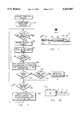
- FIG. 7illustrates a flow diagram of a computer implemented process within BMS controller 10 for controlling the battery water check fill station.
- the controllerfirst checks to determine that the probe has been returned to a home location and is in a safe position so that it will not be in the path of a battery being inserted into the station.
- the probe 68which is under control of controller 10 for positioning, normally returns to a safe location retracted from the battery when all of the battery cells have been tested.
- the systemfirst checks to determine if a battery is in position within the water check fill station, block 118.
- the transfer cart 18includes an optical reader (not shown) which is capable of reading identifying signals on batteries 14 as they are removed from and installed into the battery powered vehicles.
- the identifiermay be a bar code or other type of identifier which is readily readable by mechanical means.
- the particular battery ID within the water check fill stationis of importance to the system since it is desirable to keep track of particular cells as they pass through the station to determine if any cell is using excess water and thus indicating an overheat condition which may require that the cell be replaced.
- the probeis moved to a first cell location and inserted into the cell through the cap 70, block 122.
- the probeis inserted to a predetermined depth within a battery cell and air is applied to the probe to determine the level of liquid within the cell. If the differential pressure indicates that the cell does not need water, block 124, the program loops back to block 122 to move the probe to a next cell location. If the probe indicates that the cell does need water, a water valve is then opened, block 126, and a measured amount of water is injected into the cell. The air pressure is continued to be applied to the probe 68 so that the depth or level of water within the cell continues to be measured, block 128, until the water level is determined to be acceptable or until a predetermined time has passed, block 130.
- the programallows a second measured amount of water to be dispensed into the cell and this process continues until the time limit has been exceeded or until the cell has received an adequate amount of water. If water is added under control of a system operator, the program may prompt the operator to allow water to be added rather than actuating an automatic water feed operation. If the water level is not satisfactory when the time limit has expired, the program steps to block 132 indicating a water fill process error. The process error is recorded in the system and an appropriate indicator provided so that the system can alert the system operator of the error. If the water level is acceptable, the program steps to block 134 checking to determine if all cells have been checked and filled with water.
- the probe 68can also be used in load-testing of batteries 14.
- the station 20can include a battery connector C such as used in rack 12 to connect the batteries to a charger 42 except that the connector C connects to a controllable load L, i.e., controller 10, uses switch S to switch the load L in and out of connection to the battery.
- Probe 68is replaced with a voltage probe which can then read the voltage at each cell under load to identify bad cells.
- FIG. 8there is shown a somewhat more detailed view of the battery transfer cart 18 of a type which can be used with the present system.
- the battery transfer cartis preferably powered by an electrically driven hydraulic motor and runs on the rails 16 attached to the floor. Position control of the cart 18 is achieved by use of an incremental encoder of a type well known in the art.
- the cartis supported on each end by end members 138 and 140 which are connected together and adapted to ride on the rails 16. Between the end members 138 and 140, there is provided a vertically movable center portion 142 which can be lifted and lowered vertically by means of hydraulic motors or other means within the end members 138 and 140.
- a cross-member 144is mounted on the center member 142 and rides in a pair of opposite channels 146 and 148.
- the cross-member 144is driven by a motor (not shown) which moves the cross-member in the X direction as shown by the X arrow in FIG. 8.
- a second bracket and motor assembly 150is mounted to cross-member 144 and adapted to drive in the Y direction along cross-member 144 in order to position the paddle 152.
- the paddle 152is moved in the Y direction by the motor assembly 150 and in the X direction by the cross-member 144.
- the paddle 152is used to push or pull the batteries from and into the transfer cart 18.
- the batteriesare generally enclosed in ferromagnetic cases and the paddle 152 includes an electromagnet or vacuum cup of sufficient strength to pull the batteries from the storage rack or from the associated vehicle in which they are used.
- the transfer cart 18 of FIG. 8is adapted specifically for AGV operation in which the smaller batteries 14 are used.
- the carthas positions for three batteries, two of which are located at A and B in FIG. 8 and the other of which would be located in the slot now occupied by the paddle 152.
- the battery transfer cartalso includes an optical reader positioned to read a battery identifier located on the batteries 14.
- the optical reader(not shown) may be attached adjacent the paddle 152 with the battery identifier then being a bar code or other label attached to the end of each of the batteries 14 as shown at 154 in FIG. 8.
- the battery transfer cart 18is shown in one particular embodiment, it will be understood that various forms of transfer carts could be used for this application.
- the only constraint on the transfer cartis that it have facility for moving along the rail 16 or along a guide path which will allow the cart to move between a battery load/unload station and a storage rack or recharge station and a battery water check/fill station. It will also be recognized that if all of the batteries are loaded into the AGV's or forklift trucks at one level and all the racks are located at one level and if the battery water check/fill station is at the same level, then the need for a cart which can raise and lower the batteries may be unnecessary.
- a battery transfer cart suitable for use as cart 18may include electric or hydraulic motors for powering the cart under the control of an on-board programmable logic controller such as an Allen Bradley SLC 500 5/03 mounted in end member 140.
- the cart 18may include an optical transmitter and receiver which can detect position of an AGV (using a reflector on the AGV) to correct for variation in position of the AGV.
- the cart's PLCcan adjust cart position to correct for AGV position.
- the batteryis pushed off of the battery changing vehicle into a battery rack or onto the AGV.
- the presence of the battery and the position of the axes used to push the batteryare monitored by the PLC.
- the logic of the PLC programmingwill not permit the cart to move unless the battery pusher has reached a predetermined location, and the presence of the battery was detected.
- the electromagnetis released and the battery pusher is retracted.
- the lack of presence of the batteryis verified during the pusher retract portion of the cycle and the vehicle is inhibited from moving either horizontally or vertically until the battery pusher has fully retracted and the pusher retracted sensor is true.
- the batteryis pulled on to the vehicle from the rack, water checker or AGV.
- the battery pusherextends until contact with the battery is verified by the battery presence sensor.
- the pusherretracts to a release point and stops, checks for battery presence, releases the electromagnet, then retracts fully.
- FIG. 9there is shown a general flow chart for the operation of the battery management system of the present invention.
- the systeminitially assures that the battery transfer cart 18 has been homed or returned to a preset safe condition awaiting a vehicle to arrive for battery change, block 156.
- the host computer 21notifies BMS controller 10 that a vehicle is in transit for battery replacement, block 158
- the transfer cart 18is directed by controller 10 to get fresh batteries from a storage location and go to the vehicle battery load/unload station, block 160.
- the cartextracts batteries from the vehicle and replaces them with fresh batteries, blocks 162 and 164 and then transports the used batteries to a battery charger location, block 166.
- the BMS controller 10periodically checks to determine if there are any batteries requiring water filling, i.e., whether there are any batteries that are in the water check/fill station 20.
- the systemdetermines if there are batteries for which the water filling process has been completed and if not then checks at block 170 to determine if any batteries have completed charging so that they can be moved to the water filling station. It should be noted here that it is generally desirable to bring the batteries into the charging station and complete the recharge prior to adding water to the battery cells. Thus, if the batteries have not been charged, the program loops back to wait at block 158.
- the programinstructs the transfer cart to extract the batteries from the water filling station 20 and transfer the filled battery to a location in the storage rack 20, block 172. If any batteries have completed the charging cycle, the program instructs the cart to move the charged batteries to the water check/fill station or to storage for future water filling depending upon the need for or availability of the water check/fill station, block 174. If no batteries are ready for water filling, block 176, the program simply loops back to block 158. If there are batteries charged and ready for water filling, the system instructs the transfer cart to remove the batteries from the charging location and install them in the water check/fill station, block 178.
- FIG. 10there is shown an overall system diagram of a battery management system for both a forklift truck and for an automated guided vehicle.
- the BMS controller 10oversees the entire system and is in communication with each of the AGV's and forklift trucks in the system through the host computer 21.
- the AGV's and the forklift truckscan thereby notify the host computer 21 when they are returning to the battery replacement location so that the host computer can initiate the battery management system controller 10 to assure that fresh batteries are loaded on the cart 18 and the cart is waiting at the battery load/unload station when the vehicle arrives.
- the host computer 21is generally interfaced to the battery system controller 10 which may be a personal computer type controller, such as a type 586 PC, coupled to an operator display and control panel 182 which may include a conventional keyboard and monitor.
- the battery system controller 10provides the interface between the host computer 21 and the other components of the battery management system. Assuming that both forklift trucks and automated guided vehicles are used in a particular factory location, there may be two separate locations for battery management. One location indicated at 184 is for forklift trucks while another indication at 186 is for automated guided vehicles. The reason for the two separate locations is that the batteries for the two types of vehicles are different, both in size and weight. Accordingly, the size of the storage racks and the size of the transfer cart for each type of battery is different.
- the BMS controller 10may also operate a battery washer as previously mentioned to enable the batteries to be washed so that any contaminating material such as dirt, grease or corrosion is not picked up by the probe 68 when it is inserted into each of the battery cells.
- the battery washer 188may be the same washer for both size batteries since it is not necessary that the batteries precisely fit the washer but only that the washer be big enough to handle the largest size battery in the system.
- Each of the transfer carts 18, 18a for the AGV and the forklift areainclude their own programmable logic controller which interfaces with sensors such as the optical readers and position encoders and also interfaces with the battery manipulators such as the position of the paddle 152 along with the driving of the hydraulic motors that control motion of the carts.
- Each transfer cartalso includes within the programmable logic controller an interface with the optical sensor for bar code reading as well as the other functions performed by the carts including accurate positioning for loading and unloading batteries.
- the system controller 10in addition to its interface functions may also provide for data collection, host communication and cell supervision for monitoring of the water levels in each cell of each battery.
- the control panel 182allows for manual operation in the event of system failure. The cart 18 may also be operated manually if the BMS controller 10 fails.
Landscapes
- Engineering & Computer Science (AREA)
- Power Engineering (AREA)
- Transportation (AREA)
- Mechanical Engineering (AREA)
- Life Sciences & Earth Sciences (AREA)
- Sustainable Development (AREA)
- Sustainable Energy (AREA)
- Arrangement Or Mounting Of Propulsion Units For Vehicles (AREA)
Abstract
Description
Claims (14)
Priority Applications (3)
| Application Number | Priority Date | Filing Date | Title |
|---|---|---|---|
| US08/505,110US5545967A (en) | 1995-07-21 | 1995-07-21 | Automatic battery management system |
| PCT/US1996/011905WO1997004514A1 (en) | 1995-07-21 | 1996-07-18 | Automatic battery management system |
| AU65487/96AAU6548796A (en) | 1995-07-21 | 1996-07-18 | Automatic battery management system |
Applications Claiming Priority (1)
| Application Number | Priority Date | Filing Date | Title |
|---|---|---|---|
| US08/505,110US5545967A (en) | 1995-07-21 | 1995-07-21 | Automatic battery management system |
Publications (1)
| Publication Number | Publication Date |
|---|---|
| US5545967Atrue US5545967A (en) | 1996-08-13 |
Family
ID=24009068
Family Applications (1)
| Application Number | Title | Priority Date | Filing Date |
|---|---|---|---|
| US08/505,110Expired - Fee RelatedUS5545967A (en) | 1995-07-21 | 1995-07-21 | Automatic battery management system |
Country Status (3)
| Country | Link |
|---|---|
| US (1) | US5545967A (en) |
| AU (1) | AU6548796A (en) |
| WO (1) | WO1997004514A1 (en) |
Cited By (84)
| Publication number | Priority date | Publication date | Assignee | Title |
|---|---|---|---|---|
| US5892350A (en)* | 1993-08-31 | 1999-04-06 | Sega Enterprises, Ltd. | Battery operated self moving mobile object and charging system |
| US5998963A (en)* | 1998-06-11 | 1999-12-07 | Aarseth; Einar | Electric vehicle service center and method for exchanging and charging vehicle batteries |
| FR2780569A1 (en)* | 1998-06-24 | 1999-12-31 | Honda Motor Co Ltd | Automatic optimisation of battery recharging, particularly applicable to systems supporting battery electric vehicles |
| WO2000058139A1 (en)* | 1999-03-25 | 2000-10-05 | Nanyang Technological University | Battery system and apparatus |
| US6209573B1 (en) | 1998-06-02 | 2001-04-03 | Chin Lye Chau | Wet battery and vehicle-based water management system |
| US6278905B1 (en)* | 1998-01-28 | 2001-08-21 | Nec Corporation | Method and system for controlling robot arms of automatic guided vehicles on semiconductor wafer production line |
| US6462498B1 (en) | 2000-05-09 | 2002-10-08 | Andrew J. Filo | Self-stabilizing walking apparatus that is capable of being reprogrammed or puppeteered |
| US6705917B2 (en) | 2000-12-15 | 2004-03-16 | Andrew S. Filo | Self-phase synchronized walking and turning quadruped apparatus |
| GB2396851A (en)* | 2003-01-03 | 2004-07-07 | London Taxis Internat Ltd | Vehicle power storage unit exchange |
| US6831437B2 (en) | 2000-02-14 | 2004-12-14 | Andrew S. Filo | Walking platforms with automatic self-stabilization |
| FR2858799A1 (en)* | 2003-08-14 | 2005-02-18 | Peugeot Citroen Automobiles Sa | Electrical battery assembling method for apparatus e.g. generator, involves electrically testing charge of battery, where battery is tested while its is moved from storage zone to apparatus |
| US20050143955A1 (en)* | 2003-12-30 | 2005-06-30 | Quint Jonathan B. | Battery management system and apparatus |
| US20050149279A1 (en)* | 2003-12-30 | 2005-07-07 | Quint Jonathan B. | Battery management system and apparatus |
| US20050168226A1 (en)* | 2003-12-30 | 2005-08-04 | Quint Jonathan B. | Battery management system and apparatus |
| US20050206388A1 (en)* | 2003-12-30 | 2005-09-22 | Quint Jonathan B | Battery management system and apparatus with anomaly reporting |
| US20050234663A1 (en)* | 2003-12-30 | 2005-10-20 | Quint Jonathan B | Battery management system and apparatus with runtime analysis reporting |
| US20060089844A1 (en)* | 2004-10-26 | 2006-04-27 | Aerovironment, Inc., A California Corporation | Dynamic replenisher management |
| US20060284619A1 (en)* | 2003-12-30 | 2006-12-21 | Quint Jonathan B | Battery management system with predictive failure analysis |
| WO2008005813A3 (en)* | 2006-06-30 | 2008-02-21 | Intel Corp | Battery charger chute |
| US20080238360A1 (en)* | 2007-03-26 | 2008-10-02 | The Gillette Company | Battery Charger with Mechanism to Automatically Load and Unload Batteries |
| US20090011616A1 (en)* | 2007-07-04 | 2009-01-08 | Satyajit Patwardhan | Widely deployable charging system for vehicles |
| US20090024232A1 (en)* | 2004-10-26 | 2009-01-22 | Aerovironment, Inc. | Reactive Replenishable Device Management |
| US20090067967A1 (en)* | 2007-09-07 | 2009-03-12 | Multi-Shifter Inc. | Battery-changing vehicle with cantilevered boom |
| US20090139940A1 (en)* | 2007-11-30 | 2009-06-04 | Sackett Material Handling Systems, Inc. | Industrial battery charging, storage and handling system |
| WO2009068880A1 (en)* | 2007-11-27 | 2009-06-04 | Graham Harold Smith | Battery handling equipment |
| US20090198372A1 (en)* | 2008-02-05 | 2009-08-06 | Unlimited Range Electric Car Systems Company | Battery charging and transfer system for electrically powered vehicles |
| US20090252577A1 (en)* | 2008-04-04 | 2009-10-08 | Savant Automation, Inc. | Automatic load transfer device and method for automated material handling systems |
| US20090281928A1 (en)* | 2003-12-30 | 2009-11-12 | Quint Jonathan B | Battery management system with runtime reserve analysis |
| US20100019773A1 (en)* | 2008-07-28 | 2010-01-28 | Son Hong K | Battery monitoring device |
| US20100138095A1 (en)* | 2008-12-01 | 2010-06-03 | Redmann Jr Jerry L | Power source monitoring system for agvs and method |
| US20100308769A1 (en)* | 2008-01-31 | 2010-12-09 | Toyota Jidosha Kabushiki Kaisha | Method and system for managing charge of automated guided vehicle |
| US20120045303A1 (en)* | 2009-04-24 | 2012-02-23 | Storefront.Com Online Inc. | Automated battery and data delivery system |
| US20120068664A1 (en)* | 2009-06-10 | 2012-03-22 | Gottwald Port Technology Gmbh | System for replacing a battery of a ground transportation vehicle, particularly of an unmanned heavy-duty transportation vehicle for iso containers |
| WO2012093233A1 (en)* | 2011-01-06 | 2012-07-12 | Yves Quemeneur | Device for exchanging a removable container for an electric battery of an electric vehicle, associated removable container and associated removable container exchange station |
| CN102756715A (en)* | 2011-04-28 | 2012-10-31 | 大叶大学 | Battery exchange system and exchange method thereof |
| WO2013017793A1 (en)* | 2011-08-02 | 2013-02-07 | Renault Sas | Structure for storing motor vehicle batteries having a mechanism for locking the batteries in the storage cells |
| US8450969B2 (en) | 2011-02-28 | 2013-05-28 | Toyota Motor Engineering & Manufacturing North America, Inc. | System for automatically charging electrically powered automated guided vehicles |
| US20130218333A1 (en)* | 2011-11-18 | 2013-08-22 | Shandong Electric Power Research Institute | Current alternating robot system and method of electric bus |
| EP2679436A1 (en)* | 2012-06-28 | 2014-01-01 | Motex products Co., Ltd. | System for auto-exchanging of electric vehicle battery |
| US8816534B1 (en)* | 2011-10-11 | 2014-08-26 | Ricardo Vasquez | System and method for generating, storing and transferring electrical power between a vehicle and an auxiliary application |
| US8868235B2 (en)* | 2011-05-27 | 2014-10-21 | Shandong Electric Power Research Institute | Battery quick-change system for an electric passenger car chassis having a cartesian coordinate robot |
| US8989954B1 (en)* | 2011-01-14 | 2015-03-24 | Cisco Technology, Inc. | System and method for applications management in a networked vehicular environment |
| EP2868540A4 (en)* | 2012-06-29 | 2015-07-22 | Shandong Luneng Intelligence Technology Co Ltd | BATTERY REPLACEMENT ROBOT WITH MOBILE STORAGE RACK AND BATTERY REPLACEMENT METHOD |
| US20150263541A1 (en)* | 2012-08-02 | 2015-09-17 | Nissan Motor Co., Ltd. | Battery charging management system for automated guided vehicle and battery charging management method for automated guided vehicle |
| US20150258908A1 (en)* | 2012-08-02 | 2015-09-17 | Nissan Motor Co., Ltd. | Battery charging management system of automated guided vehicle and battery charging management method |
| US20160084737A1 (en)* | 2014-09-19 | 2016-03-24 | Swisslog Logistics Inc. | Method and System for Auto Safety Verification of AGV Sensors |
| US20160368464A1 (en)* | 2015-06-17 | 2016-12-22 | Ample Inc. | Robot Assisted Modular Battery Interchanging System |
| US20170043966A1 (en)* | 2012-12-22 | 2017-02-16 | Maytronics Ltd. | Dry docking station |
| US9827865B2 (en) | 2014-12-30 | 2017-11-28 | General Electric Company | Systems and methods for recharging vehicle-mounted energy storage devices |
| US9850114B2 (en) | 2011-06-07 | 2017-12-26 | Crown Equipment Corporation | Battery transfer apparatus |
| WO2017220627A1 (en)* | 2016-06-21 | 2017-12-28 | Autostore Technology AS | Charging station with multiple power sources |
| IT201600094153A1 (en)* | 2016-09-20 | 2018-03-20 | Gd Spa | Automatic food packaging plant |
| EP2529985A3 (en)* | 2011-06-01 | 2018-03-21 | Kookmin University Industry Academy Cooperation Foundation | Battery exchanging method for electric vehicle |
| EP2582557A4 (en)* | 2010-06-21 | 2018-04-18 | Sten Corfitsen | A method for exchanging batteries in battery-powered vehicles |
| US9987938B2 (en) | 2015-12-04 | 2018-06-05 | General Electric Company | Energy storage device, exchange apparatus, and method for exchanging an energy storage device |
| DE102017101291A1 (en) | 2017-01-24 | 2018-07-26 | Lisa Dräxlmaier GmbH | METHOD FOR LOADING A BATTERY SYSTEM |
| US20180253789A1 (en)* | 2015-11-17 | 2018-09-06 | Omron Corporation | Battery reservation device and battery reservation method |
| US20180253788A1 (en)* | 2015-11-17 | 2018-09-06 | Omron Corporation | Battery reservation device and battery reservation method |
| WO2018215579A1 (en) | 2017-05-26 | 2018-11-29 | Starship Technologies Oü | A device, method and system for swapping and/or charging a battery of a mobile robot |
| WO2018215581A1 (en) | 2017-05-26 | 2018-11-29 | Starship Technologies Oü | A battery and a system for swapping and/or charging a battery of a mobile robot |
| WO2018215583A1 (en) | 2017-05-26 | 2018-11-29 | Starship Technologies Oü | A device and system for increasing tolerance in a battery station |
| US10300804B2 (en) | 2015-04-29 | 2019-05-28 | General Electric Company | Apparatus and method for automated positioning of a vehicle |
| TWI685765B (en)* | 2018-03-07 | 2020-02-21 | 光陽工業股份有限公司 | Method for changing vehicle binding of power supply device and its server |
| US10600116B2 (en)* | 2015-11-17 | 2020-03-24 | Omron Corporation | Reservation management device, reservation management system, and reservation management method |
| US10643272B2 (en) | 2015-11-17 | 2020-05-05 | Omron Corporation | Battery reservation device |
| CN111293373A (en)* | 2020-02-25 | 2020-06-16 | 广东博智林机器人有限公司 | Battery replacing method and device, battery replacing equipment, scheduling equipment and storage medium |
| CN111591159A (en)* | 2020-07-24 | 2020-08-28 | 北京极智嘉科技有限公司 | Power supply system for electric handling equipment |
| CN111775765A (en)* | 2020-07-14 | 2020-10-16 | 武汉蔚来能源有限公司 | Vehicle and battery matching method, device, system and readable storage medium |
| CN111806284A (en)* | 2020-07-21 | 2020-10-23 | 博众精工科技股份有限公司 | Intelligent charging method and device for charging and replacing power station |
| US10933893B2 (en) | 2011-06-13 | 2021-03-02 | Transportation Ip Holdings, Llc | Vehicle electric supply system |
| IT201900015803A1 (en)* | 2019-09-06 | 2021-03-06 | Shanghai Yoyao Tech Co Ltd | REPLACEMENT SYSTEM FOR VEHICLE PROPULSION BATTERIES |
| CN112838632A (en)* | 2020-12-31 | 2021-05-25 | 北京中电瑞能新能源科技有限公司 | Intelligent charging room charging system |
| NO20200115A1 (en)* | 2020-01-29 | 2021-07-30 | Scandinavian Micromobility As | A charging and transportation system |
| EP3875310A1 (en)* | 2020-03-05 | 2021-09-08 | Solystic | Installation for handling of objects comprising a fleet of robotic shuttle type vehicles guided automatically by remote control for transporting objects |
| US11232388B2 (en)* | 2019-11-22 | 2022-01-25 | Accenture Global Solutions Limited | Automated guided vehicle systems for retrieving hems |
| JP2023030989A (en)* | 2021-08-24 | 2023-03-08 | 三菱ロジスネクスト株式会社 | Cargo handling system and control method |
| US11649088B2 (en) | 2017-07-28 | 2023-05-16 | Starship Technologies Oü | Device and system for secure package delivery by a mobile robot |
| US11650256B2 (en)* | 2017-09-29 | 2023-05-16 | Daramic, Llc | Testing apparatus for testing lead acid batteries and their components, and methods and systems incorporating the same |
| EP3810453B1 (en)* | 2018-06-19 | 2023-10-18 | Einride Ab | Predictive remote thermal managment |
| EP4216344A4 (en)* | 2021-09-28 | 2024-04-17 | Contemporary Amperex Technology Co., Limited | BATTERY STORAGE DEVICE AND LUBRICATION METHOD |
| CN118907026A (en)* | 2024-09-23 | 2024-11-08 | 国网江苏省电力有限公司电力科学研究院 | Intelligent power exchange station compatible with multiple battery packs, control method, equipment and medium |
| US12296710B2 (en) | 2023-05-16 | 2025-05-13 | Ample, Inc. | Battery-exchange service station |
| US12370919B2 (en) | 2024-09-23 | 2025-07-29 | State Grid Jiangsu Electric Power Company Research Institute | Smart battery swapping station compatible with multiple battery packs, control method thereof, device, and medium |
| US12421088B2 (en) | 2023-05-16 | 2025-09-23 | Ample, Inc. | Configurable vehicle lift and service station |
Citations (10)
| Publication number | Priority date | Publication date | Assignee | Title |
|---|---|---|---|---|
| US3630788A (en)* | 1969-08-04 | 1971-12-28 | Globe Union Inc | Venting and filling device for storage batteries |
| US3880209A (en)* | 1974-05-09 | 1975-04-29 | David C Haughn | Automatic-level battery cell liquid filling portable device |
| US3957093A (en)* | 1975-02-13 | 1976-05-18 | Stoner Joel A | Liquid supply device with automatic flow cut-off |
| US4227463A (en)* | 1978-03-27 | 1980-10-14 | Pflow Industries, Inc. | Apparatus for removing and installing batteries |
| US4334819A (en)* | 1980-03-27 | 1982-06-15 | Hammerslag Julius G | Battery charging system |
| US4499424A (en)* | 1982-04-09 | 1985-02-12 | The United States Of America As Represented By The Administrator Of The National Aeronautics And Space Administration | State-of-charge coulometer |
| US4583286A (en)* | 1983-03-28 | 1986-04-22 | Gnb Batteries Inc. | Apparatus and method for processing and transferring battery cell elements |
| US4983903A (en)* | 1988-07-13 | 1991-01-08 | Samsung Electronics Co., Ltd. | Automatic battery exchanging system for automatic guided vehicles |
| US5091687A (en)* | 1989-07-31 | 1992-02-25 | Maschinenfabrik Rieter Ag | Apparatus for exchanging and charging of energy storages of transport vehicles |
| US5132176A (en)* | 1990-05-03 | 1992-07-21 | Gnb Industrial Battery Company | Battery state of charge indicator |
- 1995
- 1995-07-21USUS08/505,110patent/US5545967A/ennot_activeExpired - Fee Related
- 1996
- 1996-07-18AUAU65487/96Apatent/AU6548796A/ennot_activeAbandoned
- 1996-07-18WOPCT/US1996/011905patent/WO1997004514A1/enactiveApplication Filing
Patent Citations (10)
| Publication number | Priority date | Publication date | Assignee | Title |
|---|---|---|---|---|
| US3630788A (en)* | 1969-08-04 | 1971-12-28 | Globe Union Inc | Venting and filling device for storage batteries |
| US3880209A (en)* | 1974-05-09 | 1975-04-29 | David C Haughn | Automatic-level battery cell liquid filling portable device |
| US3957093A (en)* | 1975-02-13 | 1976-05-18 | Stoner Joel A | Liquid supply device with automatic flow cut-off |
| US4227463A (en)* | 1978-03-27 | 1980-10-14 | Pflow Industries, Inc. | Apparatus for removing and installing batteries |
| US4334819A (en)* | 1980-03-27 | 1982-06-15 | Hammerslag Julius G | Battery charging system |
| US4499424A (en)* | 1982-04-09 | 1985-02-12 | The United States Of America As Represented By The Administrator Of The National Aeronautics And Space Administration | State-of-charge coulometer |
| US4583286A (en)* | 1983-03-28 | 1986-04-22 | Gnb Batteries Inc. | Apparatus and method for processing and transferring battery cell elements |
| US4983903A (en)* | 1988-07-13 | 1991-01-08 | Samsung Electronics Co., Ltd. | Automatic battery exchanging system for automatic guided vehicles |
| US5091687A (en)* | 1989-07-31 | 1992-02-25 | Maschinenfabrik Rieter Ag | Apparatus for exchanging and charging of energy storages of transport vehicles |
| US5132176A (en)* | 1990-05-03 | 1992-07-21 | Gnb Industrial Battery Company | Battery state of charge indicator |
Cited By (141)
| Publication number | Priority date | Publication date | Assignee | Title |
|---|---|---|---|---|
| US5892350A (en)* | 1993-08-31 | 1999-04-06 | Sega Enterprises, Ltd. | Battery operated self moving mobile object and charging system |
| US6278905B1 (en)* | 1998-01-28 | 2001-08-21 | Nec Corporation | Method and system for controlling robot arms of automatic guided vehicles on semiconductor wafer production line |
| US6431201B2 (en) | 1998-06-02 | 2002-08-13 | Chin Lye Chau | Wet battery and vehicle-based water management system |
| US6209573B1 (en) | 1998-06-02 | 2001-04-03 | Chin Lye Chau | Wet battery and vehicle-based water management system |
| US5998963A (en)* | 1998-06-11 | 1999-12-07 | Aarseth; Einar | Electric vehicle service center and method for exchanging and charging vehicle batteries |
| FR2780569A1 (en)* | 1998-06-24 | 1999-12-31 | Honda Motor Co Ltd | Automatic optimisation of battery recharging, particularly applicable to systems supporting battery electric vehicles |
| NL1012031C2 (en)* | 1998-06-24 | 2001-08-02 | Honda Motor Co Ltd | Battery charge control device for battery change system. |
| WO2000058139A1 (en)* | 1999-03-25 | 2000-10-05 | Nanyang Technological University | Battery system and apparatus |
| US6831437B2 (en) | 2000-02-14 | 2004-12-14 | Andrew S. Filo | Walking platforms with automatic self-stabilization |
| US6462498B1 (en) | 2000-05-09 | 2002-10-08 | Andrew J. Filo | Self-stabilizing walking apparatus that is capable of being reprogrammed or puppeteered |
| WO2001085400A3 (en)* | 2000-05-09 | 2009-06-04 | Hasbro Inc | Self-stabilizing walking apparatus that is capable of being reprogrammed or puppeteered |
| US6705917B2 (en) | 2000-12-15 | 2004-03-16 | Andrew S. Filo | Self-phase synchronized walking and turning quadruped apparatus |
| GB2396851A (en)* | 2003-01-03 | 2004-07-07 | London Taxis Internat Ltd | Vehicle power storage unit exchange |
| FR2858799A1 (en)* | 2003-08-14 | 2005-02-18 | Peugeot Citroen Automobiles Sa | Electrical battery assembling method for apparatus e.g. generator, involves electrically testing charge of battery, where battery is tested while its is moved from storage zone to apparatus |
| US7003431B2 (en)* | 2003-12-30 | 2006-02-21 | Quint Jonathan B | Battery management system and apparatus |
| US20050149279A1 (en)* | 2003-12-30 | 2005-07-07 | Quint Jonathan B. | Battery management system and apparatus |
| US20050206388A1 (en)* | 2003-12-30 | 2005-09-22 | Quint Jonathan B | Battery management system and apparatus with anomaly reporting |
| US20050234663A1 (en)* | 2003-12-30 | 2005-10-20 | Quint Jonathan B | Battery management system and apparatus with runtime analysis reporting |
| US20090281928A1 (en)* | 2003-12-30 | 2009-11-12 | Quint Jonathan B | Battery management system with runtime reserve analysis |
| US7616002B2 (en) | 2003-12-30 | 2009-11-10 | Batterycorp, Inc. | Battery management system and apparatus with anomaly reporting |
| US20060284619A1 (en)* | 2003-12-30 | 2006-12-21 | Quint Jonathan B | Battery management system with predictive failure analysis |
| US7206704B2 (en) | 2003-12-30 | 2007-04-17 | Batterycorp., Inc. | Battery management system and apparatus |
| US7317995B2 (en) | 2003-12-30 | 2008-01-08 | Batterycorp., Inc. | Battery management system and apparatus |
| US7750639B2 (en) | 2003-12-30 | 2010-07-06 | Batterycorp, Inc. | Battery management system with predictive failure analysis |
| US7349816B2 (en) | 2003-12-30 | 2008-03-25 | Batterycorp, Inc. | Battery management system and apparatus with runtime analysis reporting |
| US20050168226A1 (en)* | 2003-12-30 | 2005-08-04 | Quint Jonathan B. | Battery management system and apparatus |
| US20050143955A1 (en)* | 2003-12-30 | 2005-06-30 | Quint Jonathan B. | Battery management system and apparatus |
| US7915860B2 (en) | 2003-12-30 | 2011-03-29 | Batterycorp, Inc. | Battery management system with runtime reserve analysis |
| US7996098B2 (en) | 2004-10-26 | 2011-08-09 | Aerovironment, Inc. | Reactive replenishable device management |
| AU2005299352B9 (en)* | 2004-10-26 | 2011-07-21 | Webasto Charging Systems, Inc. | Reactive replenishable device management |
| AU2005299352B2 (en)* | 2004-10-26 | 2011-04-28 | Webasto Charging Systems, Inc. | Reactive replenishable device management |
| US20090024232A1 (en)* | 2004-10-26 | 2009-01-22 | Aerovironment, Inc. | Reactive Replenishable Device Management |
| EP2439524A1 (en)* | 2004-10-26 | 2012-04-11 | Aerovironment inc. | Reactive replenishable device management |
| US20100332076A1 (en)* | 2004-10-26 | 2010-12-30 | Aerovironment, Inc. | Reactive replenishable device management |
| EP1831677A4 (en)* | 2004-10-26 | 2009-09-02 | Aerovironment Inc | Reactive replenishable device management |
| US9059485B2 (en) | 2004-10-26 | 2015-06-16 | Aerovironment, Inc. | Reactive replenishable device management |
| US20060089844A1 (en)* | 2004-10-26 | 2006-04-27 | Aerovironment, Inc., A California Corporation | Dynamic replenisher management |
| US9849788B2 (en) | 2004-10-26 | 2017-12-26 | Aerovironment, Inc. | Reactive replenishable device management |
| US7723951B2 (en) | 2006-06-30 | 2010-05-25 | Intel Corporation | Battery charging apparatus having a chute and method of recharging a battery |
| WO2008005813A3 (en)* | 2006-06-30 | 2008-02-21 | Intel Corp | Battery charger chute |
| CN101454959B (en)* | 2006-06-30 | 2015-09-09 | 英特尔公司 | Battery charger chute |
| US8120315B2 (en) | 2007-03-26 | 2012-02-21 | The Gillette Company | Battery charger with mechanism to automatically load and unload batteries |
| US20080238360A1 (en)* | 2007-03-26 | 2008-10-02 | The Gillette Company | Battery Charger with Mechanism to Automatically Load and Unload Batteries |
| US7800341B2 (en)* | 2007-03-26 | 2010-09-21 | The Gillette Company | Battery charger with mechanism to automatically load and unload batteries |
| US20100301804A1 (en)* | 2007-03-26 | 2010-12-02 | The Gillette Company, A Delaware Corporation | Battery Charger with Mechanism to Automatically Load and Unload Batteries |
| US8307967B2 (en) | 2007-07-04 | 2012-11-13 | Satyajit Patwardhan | Widely deployable charging system for vehicles |
| US20090011616A1 (en)* | 2007-07-04 | 2009-01-08 | Satyajit Patwardhan | Widely deployable charging system for vehicles |
| US8025474B2 (en) | 2007-09-07 | 2011-09-27 | Multi-Shifter, Inc. | Battery-changing vehicle with cantilevered boom |
| US7938612B2 (en) | 2007-09-07 | 2011-05-10 | Multi-Shifter, Inc. | Battery-changing vehicle with cantilevered boom |
| US20110176906A1 (en)* | 2007-09-07 | 2011-07-21 | Multi-Shifter, Inc. | Battery-changing vehicle with cantilevered boom |
| WO2009032822A1 (en)* | 2007-09-07 | 2009-03-12 | Multi-Shifter, Inc. | Battery-changing vehicle with cantilevered boom |
| US20090067967A1 (en)* | 2007-09-07 | 2009-03-12 | Multi-Shifter Inc. | Battery-changing vehicle with cantilevered boom |
| WO2009068880A1 (en)* | 2007-11-27 | 2009-06-04 | Graham Harold Smith | Battery handling equipment |
| US8366371B2 (en)* | 2007-11-30 | 2013-02-05 | Sacket Material Handling Systems, Inc. | Industrial battery charging, storage and handling system |
| US20090139940A1 (en)* | 2007-11-30 | 2009-06-04 | Sackett Material Handling Systems, Inc. | Industrial battery charging, storage and handling system |
| US20100308769A1 (en)* | 2008-01-31 | 2010-12-09 | Toyota Jidosha Kabushiki Kaisha | Method and system for managing charge of automated guided vehicle |
| US8288989B2 (en)* | 2008-01-31 | 2012-10-16 | Toyota Jidosha Kabushiki Kaisha | Method and system for managing charge of automated guided vehicle |
| US20090198372A1 (en)* | 2008-02-05 | 2009-08-06 | Unlimited Range Electric Car Systems Company | Battery charging and transfer system for electrically powered vehicles |
| US8047756B2 (en) | 2008-04-04 | 2011-11-01 | Savant Automation, Inc. | Automatic load transfer device and method for automated material handling systems |
| US20090252577A1 (en)* | 2008-04-04 | 2009-10-08 | Savant Automation, Inc. | Automatic load transfer device and method for automated material handling systems |
| US20100019773A1 (en)* | 2008-07-28 | 2010-01-28 | Son Hong K | Battery monitoring device |
| US7890228B2 (en) | 2008-12-01 | 2011-02-15 | Savant Automation, Inc. | Power source monitoring system for AGVs and method |
| US20100138095A1 (en)* | 2008-12-01 | 2010-06-03 | Redmann Jr Jerry L | Power source monitoring system for agvs and method |
| US20120045303A1 (en)* | 2009-04-24 | 2012-02-23 | Storefront.Com Online Inc. | Automated battery and data delivery system |
| US8922163B2 (en)* | 2009-04-24 | 2014-12-30 | Murray MacDonald | Automated battery and data delivery system |
| US20120068664A1 (en)* | 2009-06-10 | 2012-03-22 | Gottwald Port Technology Gmbh | System for replacing a battery of a ground transportation vehicle, particularly of an unmanned heavy-duty transportation vehicle for iso containers |
| US8875826B2 (en)* | 2009-06-10 | 2014-11-04 | Terex Mhps Gmbh | System for replacing a battery of a ground transportation vehicle, particularly of an unmanned heavy-duty transportation vehicle for ISO containers |
| EP2582557A4 (en)* | 2010-06-21 | 2018-04-18 | Sten Corfitsen | A method for exchanging batteries in battery-powered vehicles |
| WO2012093233A1 (en)* | 2011-01-06 | 2012-07-12 | Yves Quemeneur | Device for exchanging a removable container for an electric battery of an electric vehicle, associated removable container and associated removable container exchange station |
| FR2970224A1 (en)* | 2011-01-06 | 2012-07-13 | Yves Quemeneur | REMOVABLE CONTAINER EXCHANGE DEVICE FOR ELECTRIC VEHICLE ELECTRIC BATTERY, ASSOCIATED REMOVABLE CONTAINER AND REMOVABLE CONTAINER EXCHANGE STATION THEREFOR |
| US8989954B1 (en)* | 2011-01-14 | 2015-03-24 | Cisco Technology, Inc. | System and method for applications management in a networked vehicular environment |
| US8450969B2 (en) | 2011-02-28 | 2013-05-28 | Toyota Motor Engineering & Manufacturing North America, Inc. | System for automatically charging electrically powered automated guided vehicles |
| CN102756715A (en)* | 2011-04-28 | 2012-10-31 | 大叶大学 | Battery exchange system and exchange method thereof |
| CN102756715B (en)* | 2011-04-28 | 2015-02-18 | 大叶大学 | Battery exchange system and exchange method thereof |
| US8868235B2 (en)* | 2011-05-27 | 2014-10-21 | Shandong Electric Power Research Institute | Battery quick-change system for an electric passenger car chassis having a cartesian coordinate robot |
| EP2529985A3 (en)* | 2011-06-01 | 2018-03-21 | Kookmin University Industry Academy Cooperation Foundation | Battery exchanging method for electric vehicle |
| US9850114B2 (en) | 2011-06-07 | 2017-12-26 | Crown Equipment Corporation | Battery transfer apparatus |
| US10933893B2 (en) | 2011-06-13 | 2021-03-02 | Transportation Ip Holdings, Llc | Vehicle electric supply system |
| WO2013017793A1 (en)* | 2011-08-02 | 2013-02-07 | Renault Sas | Structure for storing motor vehicle batteries having a mechanism for locking the batteries in the storage cells |
| FR2978717A1 (en)* | 2011-08-02 | 2013-02-08 | Renault Sa | AUTOMOTIVE VEHICLE BATTERY STORAGE STRUCTURE WITH BATTERY LOCK MECHANISM IN STORAGE CELLS |
| US8816534B1 (en)* | 2011-10-11 | 2014-08-26 | Ricardo Vasquez | System and method for generating, storing and transferring electrical power between a vehicle and an auxiliary application |
| US8660692B2 (en)* | 2011-11-18 | 2014-02-25 | State Grid Corporation Of China | Current alternating robot system and method of electric bus |
| US20130218333A1 (en)* | 2011-11-18 | 2013-08-22 | Shandong Electric Power Research Institute | Current alternating robot system and method of electric bus |
| EP2679436A1 (en)* | 2012-06-28 | 2014-01-01 | Motex products Co., Ltd. | System for auto-exchanging of electric vehicle battery |
| EP2868540A4 (en)* | 2012-06-29 | 2015-07-22 | Shandong Luneng Intelligence Technology Co Ltd | BATTERY REPLACEMENT ROBOT WITH MOBILE STORAGE RACK AND BATTERY REPLACEMENT METHOD |
| US9650022B2 (en) | 2012-06-29 | 2017-05-16 | Shandong Luneng Intelligence Technology Co., Ltd | Battery replacement robot with mobile storage rack and battery replacement method |
| US20150258908A1 (en)* | 2012-08-02 | 2015-09-17 | Nissan Motor Co., Ltd. | Battery charging management system of automated guided vehicle and battery charging management method |
| US9325192B2 (en)* | 2012-08-02 | 2016-04-26 | Nissan Motor Co., Ltd. | Battery charging management system for automated guided vehicle and battery charging management method for automated guided vehicle |
| US9428075B2 (en)* | 2012-08-02 | 2016-08-30 | Nissan Motor Co., Ltd. | Battery charging management system of automated guided vehicle and battery charging management method |
| US20150263541A1 (en)* | 2012-08-02 | 2015-09-17 | Nissan Motor Co., Ltd. | Battery charging management system for automated guided vehicle and battery charging management method for automated guided vehicle |
| US20170043966A1 (en)* | 2012-12-22 | 2017-02-16 | Maytronics Ltd. | Dry docking station |
| US10703589B2 (en)* | 2012-12-22 | 2020-07-07 | Maytronics Ltd. | Dry docking station |
| US9651458B2 (en)* | 2014-09-19 | 2017-05-16 | Swisslog Logistics Inc. | Method and system for auto safety verification of AGV sensors |
| US20160084737A1 (en)* | 2014-09-19 | 2016-03-24 | Swisslog Logistics Inc. | Method and System for Auto Safety Verification of AGV Sensors |
| US9827865B2 (en) | 2014-12-30 | 2017-11-28 | General Electric Company | Systems and methods for recharging vehicle-mounted energy storage devices |
| US10300804B2 (en) | 2015-04-29 | 2019-05-28 | General Electric Company | Apparatus and method for automated positioning of a vehicle |
| US9868421B2 (en)* | 2015-06-17 | 2018-01-16 | Ample, Inc. | Robot assisted modular battery interchanging system |
| US20160368464A1 (en)* | 2015-06-17 | 2016-12-22 | Ample Inc. | Robot Assisted Modular Battery Interchanging System |
| US10643272B2 (en) | 2015-11-17 | 2020-05-05 | Omron Corporation | Battery reservation device |
| US20180253789A1 (en)* | 2015-11-17 | 2018-09-06 | Omron Corporation | Battery reservation device and battery reservation method |
| US20180253788A1 (en)* | 2015-11-17 | 2018-09-06 | Omron Corporation | Battery reservation device and battery reservation method |
| US11010824B2 (en)* | 2015-11-17 | 2021-05-18 | Omron Corporation | Battery reservation device and battery reservation method |
| US10650444B2 (en)* | 2015-11-17 | 2020-05-12 | Omron Corporation | Battery reservation device and battery reservation method |
| US10600116B2 (en)* | 2015-11-17 | 2020-03-24 | Omron Corporation | Reservation management device, reservation management system, and reservation management method |
| US9987938B2 (en) | 2015-12-04 | 2018-06-05 | General Electric Company | Energy storage device, exchange apparatus, and method for exchanging an energy storage device |
| WO2017220627A1 (en)* | 2016-06-21 | 2017-12-28 | Autostore Technology AS | Charging station with multiple power sources |
| US10819126B2 (en) | 2016-06-21 | 2020-10-27 | Autostore Technology AS | Charging station with multiple power sources |
| EP3471994B1 (en) | 2016-06-21 | 2021-10-20 | Autostore Technology AS | Charging station with multiple power sources |
| CN109715501A (en)* | 2016-09-20 | 2019-05-03 | 吉第联合股份公司 | Food product automated package equipment |
| JP2019534210A (en)* | 2016-09-20 | 2019-11-28 | ジー.デー ソチエタ ペル アツィオニG.D Societa Per Azioni | Automatic food packaging plant |
| US11208227B2 (en) | 2016-09-20 | 2021-12-28 | G.D Societa' Per Azioni | Food products packaging automatic plant |
| WO2018055531A1 (en)* | 2016-09-20 | 2018-03-29 | G.D Società per Azioni | Food products packaging automatic plant |
| IT201600094153A1 (en)* | 2016-09-20 | 2018-03-20 | Gd Spa | Automatic food packaging plant |
| DE102017101291A1 (en) | 2017-01-24 | 2018-07-26 | Lisa Dräxlmaier GmbH | METHOD FOR LOADING A BATTERY SYSTEM |
| US11424491B2 (en) | 2017-05-26 | 2022-08-23 | Starship Technologies Oü | Battery and a system for swapping and/or charging a battery of a mobile robot |
| US11420531B2 (en) | 2017-05-26 | 2022-08-23 | Starship Technologies Oü | Device, method and system for swapping and/or charging a battery of a mobile robot |
| WO2018215581A1 (en) | 2017-05-26 | 2018-11-29 | Starship Technologies Oü | A battery and a system for swapping and/or charging a battery of a mobile robot |
| WO2018215583A1 (en) | 2017-05-26 | 2018-11-29 | Starship Technologies Oü | A device and system for increasing tolerance in a battery station |
| WO2018215579A1 (en) | 2017-05-26 | 2018-11-29 | Starship Technologies Oü | A device, method and system for swapping and/or charging a battery of a mobile robot |
| US11649088B2 (en) | 2017-07-28 | 2023-05-16 | Starship Technologies Oü | Device and system for secure package delivery by a mobile robot |
| US11650256B2 (en)* | 2017-09-29 | 2023-05-16 | Daramic, Llc | Testing apparatus for testing lead acid batteries and their components, and methods and systems incorporating the same |
| TWI685765B (en)* | 2018-03-07 | 2020-02-21 | 光陽工業股份有限公司 | Method for changing vehicle binding of power supply device and its server |
| EP3810453B1 (en)* | 2018-06-19 | 2023-10-18 | Einride Ab | Predictive remote thermal managment |
| IT201900015803A1 (en)* | 2019-09-06 | 2021-03-06 | Shanghai Yoyao Tech Co Ltd | REPLACEMENT SYSTEM FOR VEHICLE PROPULSION BATTERIES |
| US11232388B2 (en)* | 2019-11-22 | 2022-01-25 | Accenture Global Solutions Limited | Automated guided vehicle systems for retrieving hems |
| NO20200115A1 (en)* | 2020-01-29 | 2021-07-30 | Scandinavian Micromobility As | A charging and transportation system |
| CN111293373A (en)* | 2020-02-25 | 2020-06-16 | 广东博智林机器人有限公司 | Battery replacing method and device, battery replacing equipment, scheduling equipment and storage medium |
| FR3107862A1 (en)* | 2020-03-05 | 2021-09-10 | Solystic | Logistics installation comprising a fleet of robot-type vehicles automatically guided remotely for the transport of objects |
| EP3875310A1 (en)* | 2020-03-05 | 2021-09-08 | Solystic | Installation for handling of objects comprising a fleet of robotic shuttle type vehicles guided automatically by remote control for transporting objects |
| CN111775765A (en)* | 2020-07-14 | 2020-10-16 | 武汉蔚来能源有限公司 | Vehicle and battery matching method, device, system and readable storage medium |
| CN111806284B (en)* | 2020-07-21 | 2021-12-07 | 博众精工科技股份有限公司 | Intelligent charging method and device for charging and replacing power station |
| CN111806284A (en)* | 2020-07-21 | 2020-10-23 | 博众精工科技股份有限公司 | Intelligent charging method and device for charging and replacing power station |
| CN111591159A (en)* | 2020-07-24 | 2020-08-28 | 北京极智嘉科技有限公司 | Power supply system for electric handling equipment |
| CN111591159B (en)* | 2020-07-24 | 2020-11-24 | 北京极智嘉科技有限公司 | Power supply system for electric handling equipment |
| CN112838632A (en)* | 2020-12-31 | 2021-05-25 | 北京中电瑞能新能源科技有限公司 | Intelligent charging room charging system |
| JP2023030989A (en)* | 2021-08-24 | 2023-03-08 | 三菱ロジスネクスト株式会社 | Cargo handling system and control method |
| EP4216344A4 (en)* | 2021-09-28 | 2024-04-17 | Contemporary Amperex Technology Co., Limited | BATTERY STORAGE DEVICE AND LUBRICATION METHOD |
| US12296710B2 (en) | 2023-05-16 | 2025-05-13 | Ample, Inc. | Battery-exchange service station |
| US12421088B2 (en) | 2023-05-16 | 2025-09-23 | Ample, Inc. | Configurable vehicle lift and service station |
| CN118907026A (en)* | 2024-09-23 | 2024-11-08 | 国网江苏省电力有限公司电力科学研究院 | Intelligent power exchange station compatible with multiple battery packs, control method, equipment and medium |
| US12370919B2 (en) | 2024-09-23 | 2025-07-29 | State Grid Jiangsu Electric Power Company Research Institute | Smart battery swapping station compatible with multiple battery packs, control method thereof, device, and medium |
Also Published As
| Publication number | Publication date |
|---|---|
| AU6548796A (en) | 1997-02-18 |
| WO1997004514A1 (en) | 1997-02-06 |
Similar Documents
| Publication | Publication Date | Title |
|---|---|---|
| US5545967A (en) | Automatic battery management system | |
| US4983903A (en) | Automatic battery exchanging system for automatic guided vehicles | |
| CN111637675B (en) | Automatic low-temperature sample storage equipment and method | |
| CN102064579B (en) | Automatic storehouse type electric motor car power battery charging library | |
| KR102256132B1 (en) | Automated Material Handling System for Managing Carrier Internal Pollution | |
| CN108490367A (en) | Power battery automatic checkout system and method, cell safety judgement and method of disposal | |
| US8423174B2 (en) | Method and laboratory system for handling sample tube racks | |
| KR0184877B1 (en) | Automatic manufacturing system | |
| JPH10232262A (en) | Test device for semiconductor devices | |
| WO2011119586A2 (en) | Bulk transfer of storage devices using manual loading | |
| CN101114724A (en) | Nickel-hydrogen battery management system for electric vehicle | |
| KR20060045536A (en) | Transfer system of self-propelled sample holder and self-provided sample holder | |
| CN111115246B (en) | Robotic sample storage cabinet system | |
| JP7710779B1 (en) | Dark Wet Laboratory for Scientific Research | |
| US12415678B2 (en) | Chemical supply system | |
| CN109061211A (en) | It is a kind of for picking up and device and method of placing response cup and containing the equipment of the device | |
| JP2022023515A (en) | Charge/discharge inspection facility and charge/discharge inspection method using the same | |
| CN208544260U (en) | New-energy electric vehicle battery fills the system of changing automatically | |
| US20230202754A1 (en) | System and method of determining status of a charging station | |
| CN212585501U (en) | Bulk material unloading system of circular cooler | |
| CN116859168B (en) | Product aging detection system and product aging detection method | |
| WO2025161182A1 (en) | Battery electrolyte injection system and battery electrolyte injection method | |
| US20240136645A1 (en) | Rechargeable Battery Assembly for Local Use Vehicle | |
| CN218854889U (en) | Solid-state relay detection device | |
| CN212711583U (en) | Robot sample storage cabinet system |
Legal Events
| Date | Code | Title | Description |
|---|---|---|---|
| AS | Assignment | Owner name:PRECISION AUTOMATION SYSTEMS, INC., FLORIDA Free format text:ASSIGNMENT OF ASSIGNORS INTEREST;ASSIGNORS:OSBORNE, ROBERT E.;GARLOW, DAVID A.;REEL/FRAME:007608/0529 Effective date:19950719 | |
| AS | Assignment | Owner name:PAS CAPS, INC., FLORIDA Free format text:ASSIGNMENT OF ASSIGNORS INTEREST;ASSIGNOR:PRECISION AUTOMATION SYSTEMS, INC.;REEL/FRAME:009207/0333 Effective date:19980428 | |
| FPAY | Fee payment | Year of fee payment:4 | |
| FEPP | Fee payment procedure | Free format text:PAYOR NUMBER ASSIGNED (ORIGINAL EVENT CODE: ASPN); ENTITY STATUS OF PATENT OWNER: SMALL ENTITY | |
| FEPP | Fee payment procedure | Free format text:PAYER NUMBER DE-ASSIGNED (ORIGINAL EVENT CODE: RMPN); ENTITY STATUS OF PATENT OWNER: SMALL ENTITY Free format text:PAYOR NUMBER ASSIGNED (ORIGINAL EVENT CODE: ASPN); ENTITY STATUS OF PATENT OWNER: SMALL ENTITY | |
| FPAY | Fee payment | Year of fee payment:8 | |
| REMI | Maintenance fee reminder mailed | ||
| LAPS | Lapse for failure to pay maintenance fees | ||
| STCH | Information on status: patent discontinuation | Free format text:PATENT EXPIRED DUE TO NONPAYMENT OF MAINTENANCE FEES UNDER 37 CFR 1.362 | |
| FP | Lapsed due to failure to pay maintenance fee | Effective date:20080813 |