US5545463A - Heel/metatarsal structure having premolded bulges - Google Patents
Heel/metatarsal structure having premolded bulgesDownload PDFInfo
- Publication number
- US5545463A US5545463AUS08/398,919US39891995AUS5545463AUS 5545463 AUS5545463 AUS 5545463AUS 39891995 AUS39891995 AUS 39891995AUS 5545463 AUS5545463 AUS 5545463A
- Authority
- US
- United States
- Prior art keywords
- bulges
- cavities
- heel
- passageway
- bulge
- Prior art date
- Legal status (The legal status is an assumption and is not a legal conclusion. Google has not performed a legal analysis and makes no representation as to the accuracy of the status listed.)
- Expired - Lifetime
Links
- 210000001872metatarsal boneAnatomy0.000titleclaimsabstractdescription23
- 238000007789sealingMethods0.000claimsabstractdescription11
- 239000000853adhesiveSubstances0.000claimsabstractdescription5
- 230000001070adhesive effectEffects0.000claimsabstractdescription5
- 210000002683footAnatomy0.000claimsdescription13
- 239000012530fluidSubstances0.000claimsdescription8
- 238000010276constructionMethods0.000claimsdescription6
- 230000006835compressionEffects0.000description9
- 238000007906compressionMethods0.000description9
- 239000000463materialSubstances0.000description7
- 230000000694effectsEffects0.000description5
- 238000005086pumpingMethods0.000description4
- 230000035939shockEffects0.000description3
- 230000000386athletic effectEffects0.000description2
- 239000007788liquidSubstances0.000description2
- GCSZJMUFYOAHFY-SDQBBNPISA-N(1z)-1-(3-ethyl-5-hydroxy-1,3-benzothiazol-2-ylidene)propan-2-oneChemical compoundC1=C(O)C=C2N(CC)\C(=C\C(C)=O)SC2=C1GCSZJMUFYOAHFY-SDQBBNPISA-N0.000description1
- 238000010521absorption reactionMethods0.000description1
- 238000003491arrayMethods0.000description1
- 238000004891communicationMethods0.000description1
- 230000008878couplingEffects0.000description1
- 238000010168coupling processMethods0.000description1
- 238000005859coupling reactionMethods0.000description1
- 238000013016dampingMethods0.000description1
- 239000013013elastic materialSubstances0.000description1
- 238000007689inspectionMethods0.000description1
- 230000009191jumpingEffects0.000description1
- 230000007246mechanismEffects0.000description1
- 239000012528membraneSubstances0.000description1
- 239000012858resilient materialSubstances0.000description1
- 230000000630rising effectEffects0.000description1
- 238000005096rolling processMethods0.000description1
- 239000011359shock absorbing materialSubstances0.000description1
- 210000003371toeAnatomy0.000description1
- 238000009827uniform distributionMethods0.000description1
Images


Classifications
- A—HUMAN NECESSITIES
- A61—MEDICAL OR VETERINARY SCIENCE; HYGIENE
- A61F—FILTERS IMPLANTABLE INTO BLOOD VESSELS; PROSTHESES; DEVICES PROVIDING PATENCY TO, OR PREVENTING COLLAPSING OF, TUBULAR STRUCTURES OF THE BODY, e.g. STENTS; ORTHOPAEDIC, NURSING OR CONTRACEPTIVE DEVICES; FOMENTATION; TREATMENT OR PROTECTION OF EYES OR EARS; BANDAGES, DRESSINGS OR ABSORBENT PADS; FIRST-AID KITS
- A61F6/00—Contraceptive devices; Pessaries; Applicators therefor
- A61F6/02—Contraceptive devices; Pessaries; Applicators therefor for use by males
- A61F6/04—Condoms, sheaths or the like, e.g. combined with devices protecting against contagion
- A—HUMAN NECESSITIES
- A61—MEDICAL OR VETERINARY SCIENCE; HYGIENE
- A61F—FILTERS IMPLANTABLE INTO BLOOD VESSELS; PROSTHESES; DEVICES PROVIDING PATENCY TO, OR PREVENTING COLLAPSING OF, TUBULAR STRUCTURES OF THE BODY, e.g. STENTS; ORTHOPAEDIC, NURSING OR CONTRACEPTIVE DEVICES; FOMENTATION; TREATMENT OR PROTECTION OF EYES OR EARS; BANDAGES, DRESSINGS OR ABSORBENT PADS; FIRST-AID KITS
- A61F6/00—Contraceptive devices; Pessaries; Applicators therefor
- A61F6/06—Contraceptive devices; Pessaries; Applicators therefor for use by females
- F—MECHANICAL ENGINEERING; LIGHTING; HEATING; WEAPONS; BLASTING
- F16—ENGINEERING ELEMENTS AND UNITS; GENERAL MEASURES FOR PRODUCING AND MAINTAINING EFFECTIVE FUNCTIONING OF MACHINES OR INSTALLATIONS; THERMAL INSULATION IN GENERAL
- F16F—SPRINGS; SHOCK-ABSORBERS; MEANS FOR DAMPING VIBRATION
- F16F13/00—Units comprising springs of the non-fluid type as well as vibration-dampers, shock-absorbers, or fluid springs
- F16F13/04—Units comprising springs of the non-fluid type as well as vibration-dampers, shock-absorbers, or fluid springs comprising both a plastics spring and a damper, e.g. a friction damper
- F16F13/06—Units comprising springs of the non-fluid type as well as vibration-dampers, shock-absorbers, or fluid springs comprising both a plastics spring and a damper, e.g. a friction damper the damper being a fluid damper, e.g. the plastics spring not forming a part of the wall of the fluid chamber of the damper
- F16F13/08—Units comprising springs of the non-fluid type as well as vibration-dampers, shock-absorbers, or fluid springs comprising both a plastics spring and a damper, e.g. a friction damper the damper being a fluid damper, e.g. the plastics spring not forming a part of the wall of the fluid chamber of the damper the plastics spring forming at least a part of the wall of the fluid chamber of the damper
- F—MECHANICAL ENGINEERING; LIGHTING; HEATING; WEAPONS; BLASTING
- F16—ENGINEERING ELEMENTS AND UNITS; GENERAL MEASURES FOR PRODUCING AND MAINTAINING EFFECTIVE FUNCTIONING OF MACHINES OR INSTALLATIONS; THERMAL INSULATION IN GENERAL
- F16F—SPRINGS; SHOCK-ABSORBERS; MEANS FOR DAMPING VIBRATION
- F16F15/00—Suppression of vibrations in systems; Means or arrangements for avoiding or reducing out-of-balance forces, e.g. due to motion
- F16F15/02—Suppression of vibrations of non-rotating, e.g. reciprocating systems; Suppression of vibrations of rotating systems by use of members not moving with the rotating systems
- F16F15/023—Suppression of vibrations of non-rotating, e.g. reciprocating systems; Suppression of vibrations of rotating systems by use of members not moving with the rotating systems using fluid means
- A—HUMAN NECESSITIES
- A61—MEDICAL OR VETERINARY SCIENCE; HYGIENE
- A61F—FILTERS IMPLANTABLE INTO BLOOD VESSELS; PROSTHESES; DEVICES PROVIDING PATENCY TO, OR PREVENTING COLLAPSING OF, TUBULAR STRUCTURES OF THE BODY, e.g. STENTS; ORTHOPAEDIC, NURSING OR CONTRACEPTIVE DEVICES; FOMENTATION; TREATMENT OR PROTECTION OF EYES OR EARS; BANDAGES, DRESSINGS OR ABSORBENT PADS; FIRST-AID KITS
- A61F6/00—Contraceptive devices; Pessaries; Applicators therefor
- A61F6/02—Contraceptive devices; Pessaries; Applicators therefor for use by males
- A61F6/04—Condoms, sheaths or the like, e.g. combined with devices protecting against contagion
- A61F2006/041—Condoms, sheaths or the like, e.g. combined with devices protecting against contagion combined with a protective garment, e.g. underpants or mask
- A61F2006/042—Condoms, sheaths or the like, e.g. combined with devices protecting against contagion combined with a protective garment, e.g. underpants or mask covering the mouth, e.g. oral condom
- A—HUMAN NECESSITIES
- A61—MEDICAL OR VETERINARY SCIENCE; HYGIENE
- A61F—FILTERS IMPLANTABLE INTO BLOOD VESSELS; PROSTHESES; DEVICES PROVIDING PATENCY TO, OR PREVENTING COLLAPSING OF, TUBULAR STRUCTURES OF THE BODY, e.g. STENTS; ORTHOPAEDIC, NURSING OR CONTRACEPTIVE DEVICES; FOMENTATION; TREATMENT OR PROTECTION OF EYES OR EARS; BANDAGES, DRESSINGS OR ABSORBENT PADS; FIRST-AID KITS
- A61F6/00—Contraceptive devices; Pessaries; Applicators therefor
- A61F6/02—Contraceptive devices; Pessaries; Applicators therefor for use by males
- A61F6/04—Condoms, sheaths or the like, e.g. combined with devices protecting against contagion
- A61F2006/043—Condoms, sheaths or the like, e.g. combined with devices protecting against contagion with more than one barrier
- A—HUMAN NECESSITIES
- A61—MEDICAL OR VETERINARY SCIENCE; HYGIENE
- A61F—FILTERS IMPLANTABLE INTO BLOOD VESSELS; PROSTHESES; DEVICES PROVIDING PATENCY TO, OR PREVENTING COLLAPSING OF, TUBULAR STRUCTURES OF THE BODY, e.g. STENTS; ORTHOPAEDIC, NURSING OR CONTRACEPTIVE DEVICES; FOMENTATION; TREATMENT OR PROTECTION OF EYES OR EARS; BANDAGES, DRESSINGS OR ABSORBENT PADS; FIRST-AID KITS
- A61F6/00—Contraceptive devices; Pessaries; Applicators therefor
- A61F6/02—Contraceptive devices; Pessaries; Applicators therefor for use by males
- A61F6/04—Condoms, sheaths or the like, e.g. combined with devices protecting against contagion
- A61F2006/048—Condoms, sheaths or the like, e.g. combined with devices protecting against contagion with surface protuberances
- Y—GENERAL TAGGING OF NEW TECHNOLOGICAL DEVELOPMENTS; GENERAL TAGGING OF CROSS-SECTIONAL TECHNOLOGIES SPANNING OVER SEVERAL SECTIONS OF THE IPC; TECHNICAL SUBJECTS COVERED BY FORMER USPC CROSS-REFERENCE ART COLLECTIONS [XRACs] AND DIGESTS
- Y10—TECHNICAL SUBJECTS COVERED BY FORMER USPC
- Y10T—TECHNICAL SUBJECTS COVERED BY FORMER US CLASSIFICATION
- Y10T428/00—Stock material or miscellaneous articles
- Y10T428/23—Sheet including cover or casing
- Y10T428/234—Sheet including cover or casing including elements cooperating to form cells
- Y—GENERAL TAGGING OF NEW TECHNOLOGICAL DEVELOPMENTS; GENERAL TAGGING OF CROSS-SECTIONAL TECHNOLOGIES SPANNING OVER SEVERAL SECTIONS OF THE IPC; TECHNICAL SUBJECTS COVERED BY FORMER USPC CROSS-REFERENCE ART COLLECTIONS [XRACs] AND DIGESTS
- Y10—TECHNICAL SUBJECTS COVERED BY FORMER USPC
- Y10T—TECHNICAL SUBJECTS COVERED BY FORMER US CLASSIFICATION
- Y10T428/00—Stock material or miscellaneous articles
- Y10T428/24—Structurally defined web or sheet [e.g., overall dimension, etc.]
- Y10T428/24628—Nonplanar uniform thickness material
- Y10T428/24661—Forming, or cooperating to form cells
- Y—GENERAL TAGGING OF NEW TECHNOLOGICAL DEVELOPMENTS; GENERAL TAGGING OF CROSS-SECTIONAL TECHNOLOGIES SPANNING OVER SEVERAL SECTIONS OF THE IPC; TECHNICAL SUBJECTS COVERED BY FORMER USPC CROSS-REFERENCE ART COLLECTIONS [XRACs] AND DIGESTS
- Y10—TECHNICAL SUBJECTS COVERED BY FORMER USPC
- Y10T—TECHNICAL SUBJECTS COVERED BY FORMER US CLASSIFICATION
- Y10T428/00—Stock material or miscellaneous articles
- Y10T428/24—Structurally defined web or sheet [e.g., overall dimension, etc.]
- Y10T428/24942—Structurally defined web or sheet [e.g., overall dimension, etc.] including components having same physical characteristic in differing degree
Definitions
- U.S. Pat. No. 4,577,417assigned to the same assignee as the present application, discloses a sole-and-heel structure having a premolded bulge under-the heel region, a premolded bulge under the metatarsal region and a passageway between the two bulges. Air in the cavities defined by the two bulges moves back and forth in the passageway.
- the present inventioninvolves premolded bulges in the heel portion only which bulges are connected by one or more passageways, or premolded bulges in the metatarsal portion only connected by one or more passageways, or passageway connected premolded bulges in both the heel portion and in the metatarsal portion, but without passageways between the bulges in the two portions.
- a molded, one-piece resilient outer memberhaving a heel portion and/or a metatarsal portion, the outer member having interior and exterior surfaces and having a construction to be highly wear resistant to enable said exterior surface to contact a support surface during use, a plurality of bulges molded into one of the portions and projecting from the exterior surface, the bulges respectively defining cavities opening at the interior surface, the bulges projecting from the exterior surface without the application of any elevated fluid pressure in the cavities, at least one restricted passageway molded into-the outer member between the cavities and opening to the interior surface, a sealing member having a shape that matches the shape of the outer member, the sealing member being impermeable to air and having a sealing surface, and adhesive means between the sealing surface and the interior surface for hermetically attaching the sealing member to the outer member, whereby air at atmospheric pressure is permanently located in the space jointly defined by the passageway and the cavities, there being no passageways between the cavities and the other portion.
- FIG. 1is a perspective view of an air sheet having units of bulges interconnected by passageways;
- FIGS. 2a, 2b, and 2care cross-sections taken along the line 2--2 of FIG. 1;
- FIG. 2dis a plan view of one unit of FIG. 1;
- FIG. 3is a cross-sectional view of alternative configuration
- FIG. 4is a plan view of an alternative configuration
- FIGS. 5 and 6are cross-sectional views of alternative configurations
- FIGS. 7, 8 and 9illustrate the air sheet on shoe soles
- FIG. 10is a side elevational view of a shoe embodying heel structure incorporating the features of the present invention.
- FIG. 11is a bottom plan view of the shoe of FIG. 10 on an enlarged scale
- FIG. 12is a fragmentary view taken in longitudinal section of the heel structure, along the line 12--12 of FIG. 11, on an enlarged scale;
- FIGS. 13-28depict fragmentary heel portions of a shoe incorporating various embodiments of the present invention.
- FIG. 29is a plan view of a heel/sole structure incorporating another embodiment of the present invention.
- FIG. 30is a sectional view along the line 30--30 of FIG. 29;
- FIG. 31is a plan view of a heel/sole structure incorporating another embodiment of the present invention.
- FIG. 32is a sectional view along the line 32--32 of FIG. 31;
- FIG. 33is a sectional view along the line 33--33 of FIG. 31.
- a sheet of shock absorbing material 10includes a flat or planar configured base sheet 12 overlaid by a top sheet 14 of resilient or elastic material deformed upwardly at regular intervals to define upwardly extending but downwardly open relatively large bubbles or bulges 16 forming cavities 17, and adjacent smaller bubbles or bulges 18 forming cavities 19, the two being joined together by a communicating passageway 20.
- the upper sheet 14is glued or otherwise bonded to the lower base sheet 12 so as to close the cavities and form the relatively large cavities 17 in bulges 16 and the relatively small cavities 19 in smaller bulges 18.
- the cavities 17 and 19 of each large/small pairare intercommunicated by a passageway 20 which is closed on the lower side by the base 12.
- the cavity pairsare organized and oriented to achieve high density over the upper surface area of the pad.
- the cavity sizesare depicted in FIG. 1 as large compared to the thickness of the sheet, it is to be understood that, depending on the intended application, the "large" cavities can range from small fractions of an inch in diameter to several inches in diameter. The dimensions of the smaller cavities would be scaled proportionally smaller. Similarly, the thickness of the sheet or sheets 12, 14 can, range from extremely thin membrane thicknesses to large thicknesses of several inches or more.
- FIG. 2ais a partial cross-sectional view taken along the line 2--2 of FIG. 1, it will be observed that if the pad is laid upon a planar supporting surface 22 and a compressive force F C is applied to the top of the pad by means a planar member 24, the larger bulges will be engaged and will initially resiliently resist the compression. However, as they are compressed, as depicted in FIG. 2b, the air or other fluid contained within the bulges 16 will be forced through passageways 20 into the smaller cavities 19 causing the bulges 18 to expand and rise up to be engaged by the surface 24. This is to say that as bulges 16 are collapsed they exert an upwardly directed resisting force F R1 upon the surface 22.
- both bulges 16 and 18will be resiliently collapsed, as depicted in FIG. 2c, with a second resisting force F R2 being additionally exerted by the bulge 18 of each pair.
- FIG. 2dA plan view of a unit comprising a large bulge 16 and a small bulge 18 is illustrated in FIG. 2d.
- FIG. 3is a cross-sectional view taken through an alternative embodiment is depicted wherein the bottom layer of material 30, instead of being planar, is deformed to include downwardly extending bulges 34 and 36 in mirror-image correspondence to the bulges 38 and 40 of upper sheet 32 such that a greater volume of fluid may be contained within the respective cavities 44 and 46. At least one of the sheets is provided with passageways 42 for communicatively coupling the cavities 44 and 46.
- the smaller bulgesexpand both upwardly and downwardly to engage the compressing surfaces and provide increased resilient resistance to compression.
- the larger bulges 34 and 38 in the upper and lower sheetsare generally hemispherical in configuration
- the smaller bulges 36 and 40are configured more pill-box in shape so to provide surfaces 52 and 54 which will readily expand upwardly and downwardly when subjected to increased internal pressure as would result from compression of the larger bulges 34, 38.
- the smaller cavity 46need not extend outwardly on both sides of the planes of the sheets 30 and 32. In some application it may be desirable that the small cavities distend in only one direction.
- a plurality of larger central bulges 60are each surrounded by an array of smaller satellite bulges 62 joined thereto by passageways 64.
- the large bulge/small bulge combinationstypically formed along the lines described above, are alternately rotated so as to provide a uniform distribution and high density of cavities across the surface of the material 66 forming the pad.
- two sheets of molded compressible material 70 and 72are joined at 73 to form a substantially flat outer-surfaced pad.
- the large and small cavities 74 and 76, and the communicating passageways 73are molded into the adjacent surfaces of the sheets 78 and 80, and small open cavities 77 and 79 are formed in the outer surfaces above the smaller cavities in order to allow such cavities to herniate outwardly to meet and engage the compressing surfaces.
- FIG. 6depicts a cross-section similar to that of FIG. 3 and includes the addition of an opening 90 in one of the walls forming the small cavity 92 which, via passageway 94, is in communication with a larger cavity 96.
- compression of cavity 96would force air out of passageway 94 and, assuming the materials forming the layers 97 and 98 are sufficiently resilient, removal of the compressive force would allow the materials to return to their undeformed state and cause the expelled air to return through the opening 90.
- a throttling functioncan be effected to modify the damping rate of the shock-absorbing action.
- Holes 99may be included to allow air or liquid to pass through the pad formed by the sheets 97 and 98.
- FIGS. 7 and 8depict embodiments particularly suited for footwear applications.
- a plurality of the "pumping units" 140 and 142 of the type shown in FIGS. 1-6are strategically positioned in the heel and metatarsal positions of the outer sole 144 of a shoe 146 to provide superior shock absorption.
- the large and small bulgesact as studs adding to shoe traction while at the same time cushioning the forces applied to the shoe wearer's heel and the balls of his or her feet.
- a plurality of pumping unitsis provided in the heel and metatarsal portions of a shoe.
- two multiple small units 150are provided in the heel.
- the larger bulges 152are disposed on each side of the longitudinal centerline of the shoe and the smaller bulges 154 are arranged around the outer perimeter of the heel.
- These unitswill, in addition to their shock-absorbing function, serve to provide lateral stability to the heel.
- the metatarsal units 156have their large bulges 158 positioned directly under the ball of the foot.
- the smaller bulges 160are positioned rearwardly of the bulges 158 so as to provide a forward lift as they are inflated.
- the multi-cavitied configurations depicted in the drawing and described hereinaboveform small pumping mechanisms which actively resist the collapse or compression of the sheet or other shaped material in which they are formed.
- the basic principle of the miniature pumpsis that air or other fluid trapped in the larger ball-shaped cavities, which in most embodiments protrude from the plane of the sheet, when compressed, will pass the compressed fluid through a narrow passageway to a smaller cavity which then expands to meet a compressing surface and add its resisting force to counter the compressing action.
- a weightbe dropped upon a pad of the type depicted in FIGS.
- the functionality of the present inventiondiffers materially from prior art resilient pads, bubble packs and the like.
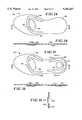
- FIG. 10there is depicted a shoe 230 having a conventional upper portion or last 231 and a so-called mid-sole 232 which is generally of wedge shape, whereby the shoe 230 is referred to as being of the "wedge-type.”
- the sole 232has a downwardly facing surface 233.
- Structure 235comprises a generally flat, thin, elongated outer member 240, the member 240 being of one-piece, molded construction, preferably rubber. In an operative embodiment, the member had a thickness of 0.125 inch. It is essential that member 240 be highly wear resistant, since it is subject to constant engagement with the pavement.
- a preferred compositionis made by Goodyear Tire & Rubber Company under its brand name INDY 500.
- Member 240has a sole portion 241 located under the sole of one's foot and a heel portion 242 located under the person's heel.
- Outer member 240has a substantially planar interior surface 243 and an exterior surface 244 which contacts the pavement.
- First and second bulges 245 and 246are molded into heel portion 242 and project downwardly from exterior surface 244.
- Bulges 245 and 246respectively define cavities 245a and 246a opening to interior surface 243.
- the cavity 245ais larger than cavity 246a.
- a restricted passageway 247is molded into outer member 240, between cavities 245a and 246a and opening to interior surface 243.
- Between surface 243 of outer member 240 and surface 233 of mid-sole 232is adhesive 248.
- Outer member 240 and mid-sole 232are thus attached, and cavities 245a and 246a are hermetically sealed, whereby air at atmospheric pressure is permanently located in the space jointly defined by cavities 245a and 246a and passageway 247.
- bulges 245 and 246engage the pavement as the wearer of shoe 230 is standing. Air in cavities 245a and 246a provide a cushioning effect. In walking and jogging, bulge 245 comes in contact with the pavement first, causing air in cavity 245a to be compressed and forced through passageway 247 into cavity 246a. As heel portion 242 lifts off the pavement, air returns to cavity 245a to give a lifting effect.
- surface 244has a tread such as is used in athletic shoes. Although a wedge type shoe is depicted, a structure in which the forward part of the heel structure is substantially vertical can be formed.
- the basic conceptis that air is used first to cushion, then to control the motion of the foot while walking, running or standing. A relatively large amount of air is moved into a smaller volume through a restricted passageway 247. Passageway 247 reduces the speed at which air moves out of main cavity 245a, thus providing cushioning. The fact that air moves from a large cavity to a small cavity 246a also provides support in the area of cavity 246a.
- the smaller front cavity 246ais on the medial side of the foot and will help reduce pronation, that is, the rolling of the foot to the inside.
- bulge 245strikes first, giving a cushion to the strike. Then, air is forced through passageway 247 to inner bulge 246, which prevents the foot from turning inward. The air further cushions the heel and returns outer bulge 245 as the weight is shifted forward and eventually lifted preparing the outer bulge 245 for the next strike.
- heel portionbeing part of a heel-and-sole structure, a separate heel portion can be provided.
- cavity 245ais larger than cavity 246a, cavity 246a is over inflated, which then forces the air back to the cavity 245a at a faster rate. This gives the heel a slight lift during walking. Air will be forced to bulge 245 and provide a slight lift to the heel as the weight rotates forward. Cavities 245a and 246a are basically fixed in size; they do not expand any significant amount.
- heel bulge 266has a generally rounded shape and is surrounded by a toroid-shaped bulge 265 with a passageway 267 between the bulges.
- each bulgeis defined by a similarly shaped cavity. Air moves back and forth between the two cavities by way of passageway 267.
- the embodiments in each of FIGS. 14 to 16have two bulges in the heel portion joined by a passageway.
- FIG. 17there are four elongated bulges 271 to 274 joined by three passageways 275 to 277 as shown. Air moves back and forth among the cavities defined by these bulges by way of such passageways.
- FIG. 18depicts a similar construction, but of different orientation.
- a larger bulge 281is located between two smaller bulges 282 and 283.
- Passageway 284connects the cavities defined by bulges 281 and 283.
- Passageway 285connects the cavities defined by bulges 281 and 282.
- the volume of air in the cavity defined by bulge 281is approximately the volume of combined air in the cavities defined by bulges 282 and 283.
- FIG. 20seven small cavities extend from one large central cavity by way of seven passageways.
- FIGS. 21, 22 and 24are similar to the embodiment of FIG. 19 in that there is one large cavity and two smaller cavities, all under the heel connected by way of a pair of passageways.
- FIG. 23there are three bulges of generally the same size.
- a pair of cavitieshas a pair of bulges joined by a passageway.
- two smaller bulgesare connected by passageways to a larger more rearwardly located bulge.
- the sole-and-heel structure depicted thereincomprise a generally flat, thin, elongated outer member 340 of one-piece, molded construction, preferably rubber, like member 240.
- Member 340has a metatarsal portion 341 located under the metatarsal region of the wearer's foot and a heel portion 342 located under the person's heel.
- Outer member 340has a substantially planar interior surface 343 and an exterior surface 344 which contacts the pavement.
- First and second bulges 345 and 346are molded into metatarsal portion 341 and project downwardly from exterior surface 344.
- Bulges 345 and 346respectively define cavities 345a and 346a opening to interior surface 343.
- a restricted passageway 347is molded into outer member 340, between cavities 345a and 346a and opening to interior surface 343.
- a member (not shown) like member 232is attached to surface 343 by adhesive so that cavities 345a and 346a are hermetically sealed, whereby air at atmospheric pressure is permanently located in the space jointly defined by cavities 345a and 346a and passageway 347.
- bulges 345 and 346engage the pavement as the wearer of shoe 330 is standing. Air in cavities in 345a and 346a provide a cushioning effect. In walking and running, bulge 345 comes in contact with the pavement, causing air in cavity 345a to be compressed and forced through passageway 347 into cavity 346a. As metatarsal portion 341 lifts off the pavement, air returns to cavity 345a to give a lifting effect.
- FIGS. 29, 30The design of FIGS. 29, 30 is used mainly in sports or for people with metatarsal problems.
- the bulgesare placed to absorb the shock of impact on the metatarsal bulge from jumping or playing tennis, for example, wherein the person is more on his or her toes.
- the center bulge 345absorbs the initial shock, forces the air through passageway 347 into the outer bulge 346.
- the air bulge 346is compressed and acts to stabilize the foot while it is on its metatarsal and also acts as a cushion. Then, when the weight is lifted air is forced back into the center larger bulge 345 because it has been compressed into that outer horse shoe-shaped bulge 346.
- surface 344has a tread such as is used in athletic shoes.
- FIGS. 32-33Yet another embodiment is depicted in FIGS. 32-33.
- an outer memberhaving bulges 365, 366 and associated cavities 365a, 366a under metatarsal portion 361 (like that depicted in FIGS. 29 and 30). It also has a pair of bulges 375, 376 and associated cavities 375a, 376a under heel portion 362 (like that depicted in FIG. 28).
- the cavities 375a, 376a in the heel portionare joined by a passageway 377 and the cavities 365a, 366a in the metatarsal portion are joined by a passageway 367, but there is no passageway between the cavities of the metatarsal portion and the heel portion.
Landscapes
- Engineering & Computer Science (AREA)
- Health & Medical Sciences (AREA)
- General Engineering & Computer Science (AREA)
- General Health & Medical Sciences (AREA)
- Veterinary Medicine (AREA)
- Vascular Medicine (AREA)
- Life Sciences & Earth Sciences (AREA)
- Animal Behavior & Ethology (AREA)
- Biomedical Technology (AREA)
- Public Health (AREA)
- Heart & Thoracic Surgery (AREA)
- Mechanical Engineering (AREA)
- Reproductive Health (AREA)
- Aviation & Aerospace Engineering (AREA)
- Acoustics & Sound (AREA)
- Physics & Mathematics (AREA)
- Footwear And Its Accessory, Manufacturing Method And Apparatuses (AREA)
Abstract
Description
Claims (8)
Priority Applications (2)
| Application Number | Priority Date | Filing Date | Title |
|---|---|---|---|
| US08/398,919US5545463A (en) | 1992-12-18 | 1995-03-06 | Heel/metatarsal structure having premolded bulges |
| US08/582,109US5679439A (en) | 1992-12-18 | 1996-01-02 | Heel/metatarsal structure having tapered stabilizing bulges |
Applications Claiming Priority (2)
| Application Number | Priority Date | Filing Date | Title |
|---|---|---|---|
| US07/993,099US5395674A (en) | 1992-12-18 | 1992-12-18 | Shock absorbing sheet material |
| US08/398,919US5545463A (en) | 1992-12-18 | 1995-03-06 | Heel/metatarsal structure having premolded bulges |
Related Parent Applications (1)
| Application Number | Title | Priority Date | Filing Date |
|---|---|---|---|
| US07/993,099Continuation-In-PartUS5395674A (en) | 1992-12-18 | 1992-12-18 | Shock absorbing sheet material |
Related Child Applications (1)
| Application Number | Title | Priority Date | Filing Date |
|---|---|---|---|
| US08/582,109Continuation-In-PartUS5679439A (en) | 1992-12-18 | 1996-01-02 | Heel/metatarsal structure having tapered stabilizing bulges |
Publications (1)
| Publication Number | Publication Date |
|---|---|
| US5545463Atrue US5545463A (en) | 1996-08-13 |
Family
ID=27016428
Family Applications (1)
| Application Number | Title | Priority Date | Filing Date |
|---|---|---|---|
| US08/398,919Expired - LifetimeUS5545463A (en) | 1992-12-18 | 1995-03-06 | Heel/metatarsal structure having premolded bulges |
Country Status (1)
| Country | Link |
|---|---|
| US (1) | US5545463A (en) |
Cited By (60)
| Publication number | Priority date | Publication date | Assignee | Title |
|---|---|---|---|---|
| US5664341A (en)* | 1996-01-02 | 1997-09-09 | Energaire Corporation | Sole and heel structure with premolded bulges and expansible cavities |
| US5679439A (en)* | 1992-12-18 | 1997-10-21 | Energaire Corporation | Heel/metatarsal structure having tapered stabilizing bulges |
| US5704137A (en)* | 1995-12-22 | 1998-01-06 | Brooks Sports, Inc. | Shoe having hydrodynamic pad |
| WO1998009546A1 (en)* | 1996-09-03 | 1998-03-12 | Reebok International Ltd. | Support and cushioning system for footwear |
| WO1998023179A1 (en) | 1996-11-26 | 1998-06-04 | Gooding Elwyn R | Adaptive, energy absorbing structure |
| USD394937S (en) | 1997-01-10 | 1998-06-09 | Reebok International Ltd. | Portion of a shoe sole |
| WO1998026196A1 (en)* | 1996-12-12 | 1998-06-18 | Grizot Gerard | Method for producing an air cushion on a receiving structure and air cushion obtained using the method |
| US5956869A (en)* | 1998-03-06 | 1999-09-28 | Energaire Corporation | Shoe sole construction with mesh liner for mid-sole cavity |
| USD414597S (en) | 1998-08-26 | 1999-10-05 | Reebok International, Ltd. | Portion of a shoe sole |
| US5992052A (en)* | 1997-10-21 | 1999-11-30 | Nottington Holding B.V. | Vapor permeable shoe with improved transpiration action |
| US6041522A (en)* | 1999-05-26 | 2000-03-28 | E.S. Originals, Inc. | Shoe structure with midsole channel between metatarsal and heel bulges |
| US6076283A (en)* | 1998-11-30 | 2000-06-20 | Srl, Inc. | Shoes and shoe outsoles for wet surfaces |
| US6082023A (en)* | 1998-02-03 | 2000-07-04 | Dalton; Edward F. | Shoe sole |
| US6092309A (en)* | 1999-03-22 | 2000-07-25 | Energaire Corporation | Heel and sole structure with inwardly projecting bulges |
| US6158149A (en)* | 1994-11-28 | 2000-12-12 | Robert C. Bogert | Article of footwear having multiple fluid containing members |
| USD443407S1 (en) | 1999-05-26 | 2001-06-12 | Spalding Sports Worldwide, Inc. | Arrangement of wear bars on a golf shoe |
| USD448920S1 (en) | 1998-08-06 | 2001-10-09 | Reebok International Ltd. | Portion of a shoe sole |
| US6354020B1 (en) | 1999-09-16 | 2002-03-12 | Reebok International Ltd. | Support and cushioning system for an article of footwear |
| US6453577B1 (en)* | 1996-02-09 | 2002-09-24 | Reebok International Ltd. | Support and cushioning system for an article of footwear |
| US6505420B1 (en) | 1996-02-09 | 2003-01-14 | Reebok International Ltd. | Cushioning member for an article of footwear |
| US20030217484A1 (en)* | 2002-05-24 | 2003-11-27 | Brian Christensen | Shoe sole having a resilient insert |
| US20050011085A1 (en)* | 2003-07-16 | 2005-01-20 | Nike, Inc. | Footwear with a sole structure incorporating a lobed fluid-filled chamber |
| US20050028403A1 (en)* | 2003-08-04 | 2005-02-10 | Nike, Inc. | Footwear sole structure incorporating a cushioning component |
| US20050283999A1 (en)* | 2004-06-25 | 2005-12-29 | Cronus, Inc. | Footwear system |
| US7080467B2 (en) | 2003-06-27 | 2006-07-25 | Reebok International Ltd. | Cushioning sole for an article of footwear |
| US20060230635A1 (en)* | 2005-04-14 | 2006-10-19 | Nike, Inc. | Fluid-filled bladder for footwear and other applications |
| US7353625B2 (en) | 2003-11-03 | 2008-04-08 | Reebok International, Ltd. | Resilient cushioning device for the heel portion of a sole |
| US7383648B1 (en) | 2004-02-23 | 2008-06-10 | Reebok International Ltd. | Inflatable support system for an article of footwear |
| US7401420B2 (en) | 2003-12-23 | 2008-07-22 | Nike, Inc. | Article of footwear having a fluid-filled bladder with a reinforcing structure |
| US7448150B1 (en) | 2004-02-26 | 2008-11-11 | Reebok International Ltd. | Insert with variable cushioning and support and article of footwear containing same |
| US20090151197A1 (en)* | 2005-04-14 | 2009-06-18 | Nike, Inc. | Fluid-Filled Bladder For Footwear And Other Applications |
| US7707745B2 (en) | 2003-07-16 | 2010-05-04 | Nike, Inc. | Footwear with a sole structure incorporating a lobed fluid-filled chamber |
| US7810255B2 (en) | 2007-02-06 | 2010-10-12 | Nike, Inc. | Interlocking fluid-filled chambers for an article of footwear |
| US20110072684A1 (en)* | 2009-09-25 | 2011-03-31 | Aci International | Support structures in footwear |
| US7950169B2 (en) | 2007-05-10 | 2011-05-31 | Nike, Inc. | Contoured fluid-filled chamber |
| USD677041S1 (en) | 2010-09-20 | 2013-03-05 | The Rockport Company, Llc | Heel of a shoe sole |
| US8657979B2 (en) | 2003-12-23 | 2014-02-25 | Nike, Inc. | Method of manufacturing a fluid-filled bladder with a reinforcing structure |
| US9119438B2 (en) | 2011-12-05 | 2015-09-01 | Nike, Inc. | Sole member for an article of footwear |
| USD758058S1 (en) | 2015-06-25 | 2016-06-07 | Spenco Medical Corporation | Heel cup |
| USD761543S1 (en) | 2015-06-25 | 2016-07-19 | Spenco Medical Corporation | Shoe insole |
| USD762367S1 (en) | 2015-06-25 | 2016-08-02 | Spenco Medical Corporation | Shoe insole |
| USD762366S1 (en) | 2015-06-25 | 2016-08-02 | Spenco Medical Corporation | Shoe insole |
| USD762368S1 (en) | 2015-06-25 | 2016-08-02 | Spenco Medical Corporation | Shoe insole |
| USD766560S1 (en) | 2015-06-25 | 2016-09-20 | Implus Footcare, Llc | Shoe insole |
| USD771922S1 (en) | 2015-09-15 | 2016-11-22 | Implus Footcare, Llc | Shoe insole |
| USD771921S1 (en) | 2015-06-25 | 2016-11-22 | Implus Footcare, Llc | Shoe insole |
| USD778040S1 (en) | 2015-09-25 | 2017-02-07 | Implus Footcare, Llc | Shoe insole |
| USD778567S1 (en) | 2015-09-17 | 2017-02-14 | Implus Footcare, Llc | Shoe insole |
| USD797430S1 (en) | 2015-07-15 | 2017-09-19 | Implus Footcare, Llc | Shoe insole |
| USD797428S1 (en) | 2015-07-15 | 2017-09-19 | Implus Footcare, Llc | Shoe insole |
| USD797429S1 (en) | 2015-07-15 | 2017-09-19 | Implus Footcare, Llc | Shoe insole |
| US9788602B2 (en) | 2012-08-31 | 2017-10-17 | Implus Footcare, Llc | Basketball insole |
| US9930926B2 (en) | 2010-06-25 | 2018-04-03 | Implus Footcare, Llc | Contoured support insole |
| USD814750S1 (en) | 2015-09-25 | 2018-04-10 | Fourfoot, Llc | Sandal |
| US9961958B1 (en) | 2015-05-28 | 2018-05-08 | Implus Footcare, Llc | Contoured support shoe insole |
| US10136698B2 (en) | 2015-05-28 | 2018-11-27 | Implus Footcare, Llc | Shoe insole |
| US10441023B2 (en) | 2011-02-02 | 2019-10-15 | Implus Footcare, Llc | Flow insole |
| US10485299B2 (en) | 2015-05-28 | 2019-11-26 | Implus Footcare, Llc | Contoured support shoe insole |
| US10709203B2 (en) | 2015-05-28 | 2020-07-14 | Implus Footcare, Llc | Contoured support shoe insole |
| US20240180291A1 (en)* | 2022-12-05 | 2024-06-06 | Reebok International Limited | Article of footwear having a reflectively symmetrical fluid cushioning system |
Citations (10)
| Publication number | Priority date | Publication date | Assignee | Title |
|---|---|---|---|---|
| US745793A (en)* | 1902-07-16 | 1903-12-01 | William C Corman | Elastic pad for heels. |
| US1977695A (en)* | 1933-06-10 | 1934-10-23 | Howard W Dix | Heel |
| US2532742A (en)* | 1949-02-17 | 1950-12-05 | Stoiner Stephen | Cushion heel |
| DE871261C (en)* | 1942-08-07 | 1953-05-11 | Continental Gummi Werke Ag | Sole for footwear |
| US3044190A (en)* | 1959-12-18 | 1962-07-17 | Urbany Urban | Inflatable sole and heel structure with replaceable tread portions |
| DE1287477B (en)* | 1961-07-08 | 1969-01-16 | Opel Georg Von | Pneumatic sole for shoes |
| US4071963A (en)* | 1976-04-14 | 1978-02-07 | Sadao Fukuoka | Ventilated footwear |
| US4224749A (en)* | 1978-12-26 | 1980-09-30 | Diaz Cano Juan A | Heels for footwear |
| US4358902A (en)* | 1980-04-02 | 1982-11-16 | Cole George S | Thrust producing shoe sole and heel |
| US5395674A (en)* | 1992-12-18 | 1995-03-07 | Schmidt; K. Michael | Shock absorbing sheet material |
- 1995
- 1995-03-06USUS08/398,919patent/US5545463A/ennot_activeExpired - Lifetime
Patent Citations (10)
| Publication number | Priority date | Publication date | Assignee | Title |
|---|---|---|---|---|
| US745793A (en)* | 1902-07-16 | 1903-12-01 | William C Corman | Elastic pad for heels. |
| US1977695A (en)* | 1933-06-10 | 1934-10-23 | Howard W Dix | Heel |
| DE871261C (en)* | 1942-08-07 | 1953-05-11 | Continental Gummi Werke Ag | Sole for footwear |
| US2532742A (en)* | 1949-02-17 | 1950-12-05 | Stoiner Stephen | Cushion heel |
| US3044190A (en)* | 1959-12-18 | 1962-07-17 | Urbany Urban | Inflatable sole and heel structure with replaceable tread portions |
| DE1287477B (en)* | 1961-07-08 | 1969-01-16 | Opel Georg Von | Pneumatic sole for shoes |
| US4071963A (en)* | 1976-04-14 | 1978-02-07 | Sadao Fukuoka | Ventilated footwear |
| US4224749A (en)* | 1978-12-26 | 1980-09-30 | Diaz Cano Juan A | Heels for footwear |
| US4358902A (en)* | 1980-04-02 | 1982-11-16 | Cole George S | Thrust producing shoe sole and heel |
| US5395674A (en)* | 1992-12-18 | 1995-03-07 | Schmidt; K. Michael | Shock absorbing sheet material |
Cited By (96)
| Publication number | Priority date | Publication date | Assignee | Title |
|---|---|---|---|---|
| US5679439A (en)* | 1992-12-18 | 1997-10-21 | Energaire Corporation | Heel/metatarsal structure having tapered stabilizing bulges |
| US8434244B2 (en) | 1994-01-26 | 2013-05-07 | Reebok International Limited | Support and cushioning system for an article of footwear |
| US7475498B2 (en) | 1994-01-26 | 2009-01-13 | Reebok International Ltd. | Support and cushioning system for an article of footwear |
| US7181867B2 (en) | 1994-01-26 | 2007-02-27 | Reebok International Ltd. | Support and cushioning system for an article of footwear |
| US5771606A (en)* | 1994-10-14 | 1998-06-30 | Reebok International Ltd. | Support and cushioning system for an article of footwear |
| US6845573B2 (en) | 1994-10-14 | 2005-01-25 | Reebok International Ltd. | Support and cushioning system for an article of footwear |
| US6457263B1 (en) | 1994-11-28 | 2002-10-01 | Marion Franklin Rudy | Article of footwear having multiple fluid containing members |
| US6158149A (en)* | 1994-11-28 | 2000-12-12 | Robert C. Bogert | Article of footwear having multiple fluid containing members |
| US5704137A (en)* | 1995-12-22 | 1998-01-06 | Brooks Sports, Inc. | Shoe having hydrodynamic pad |
| US5664341A (en)* | 1996-01-02 | 1997-09-09 | Energaire Corporation | Sole and heel structure with premolded bulges and expansible cavities |
| US6505420B1 (en) | 1996-02-09 | 2003-01-14 | Reebok International Ltd. | Cushioning member for an article of footwear |
| US6453577B1 (en)* | 1996-02-09 | 2002-09-24 | Reebok International Ltd. | Support and cushioning system for an article of footwear |
| WO1998009546A1 (en)* | 1996-09-03 | 1998-03-12 | Reebok International Ltd. | Support and cushioning system for footwear |
| WO1998023179A1 (en) | 1996-11-26 | 1998-06-04 | Gooding Elwyn R | Adaptive, energy absorbing structure |
| US5915819A (en)* | 1996-11-26 | 1999-06-29 | Gooding; Elwyn | Adaptive, energy absorbing structure |
| WO1998026196A1 (en)* | 1996-12-12 | 1998-06-18 | Grizot Gerard | Method for producing an air cushion on a receiving structure and air cushion obtained using the method |
| USD448543S1 (en) | 1997-01-10 | 2001-10-02 | Reebok International Ltd. | Portion of a shoe sole |
| USD451264S1 (en) | 1997-01-10 | 2001-12-04 | Reebok International Ltd. | Portion of a shoe sole |
| USD446003S1 (en) | 1997-01-10 | 2001-08-07 | Reebok International Ltd. | Portion of a shoe sole |
| USD447324S1 (en) | 1997-01-10 | 2001-09-04 | Reebok International Ltd. | Portion of a shoe sole |
| USD448538S1 (en) | 1997-01-10 | 2001-09-25 | Reebok International Ltd. | Shoe outsole |
| USD394937S (en) | 1997-01-10 | 1998-06-09 | Reebok International Ltd. | Portion of a shoe sole |
| USD453988S1 (en) | 1997-01-10 | 2002-03-05 | Reebok International Ltd. | Portion of a shoe |
| US5992052A (en)* | 1997-10-21 | 1999-11-30 | Nottington Holding B.V. | Vapor permeable shoe with improved transpiration action |
| US6082023A (en)* | 1998-02-03 | 2000-07-04 | Dalton; Edward F. | Shoe sole |
| US5956869A (en)* | 1998-03-06 | 1999-09-28 | Energaire Corporation | Shoe sole construction with mesh liner for mid-sole cavity |
| USD448920S1 (en) | 1998-08-06 | 2001-10-09 | Reebok International Ltd. | Portion of a shoe sole |
| USD414597S (en) | 1998-08-26 | 1999-10-05 | Reebok International, Ltd. | Portion of a shoe sole |
| US6076283A (en)* | 1998-11-30 | 2000-06-20 | Srl, Inc. | Shoes and shoe outsoles for wet surfaces |
| US6092309A (en)* | 1999-03-22 | 2000-07-25 | Energaire Corporation | Heel and sole structure with inwardly projecting bulges |
| US6041522A (en)* | 1999-05-26 | 2000-03-28 | E.S. Originals, Inc. | Shoe structure with midsole channel between metatarsal and heel bulges |
| USD443407S1 (en) | 1999-05-26 | 2001-06-12 | Spalding Sports Worldwide, Inc. | Arrangement of wear bars on a golf shoe |
| US6354020B1 (en) | 1999-09-16 | 2002-03-12 | Reebok International Ltd. | Support and cushioning system for an article of footwear |
| US6745499B2 (en) | 2002-05-24 | 2004-06-08 | Reebok International Ltd. | Shoe sole having a resilient insert |
| US20030217484A1 (en)* | 2002-05-24 | 2003-11-27 | Brian Christensen | Shoe sole having a resilient insert |
| US7080467B2 (en) | 2003-06-27 | 2006-07-25 | Reebok International Ltd. | Cushioning sole for an article of footwear |
| US20100170108A1 (en)* | 2003-07-16 | 2010-07-08 | Nike, Inc. | Footwear With A Sole Structure Incorporating A Lobed Fluid-Filled Chamber |
| US7000335B2 (en)* | 2003-07-16 | 2006-02-21 | Nike, Inc. | Footwear with a sole structure incorporating a lobed fluid-filled chamber |
| US8631588B2 (en) | 2003-07-16 | 2014-01-21 | Nike, Inc. | Footwear with a sole structure incorporating a lobed fluid-filled chamber |
| US8001703B2 (en) | 2003-07-16 | 2011-08-23 | Nike, Inc. | Footwear with a sole structure incorporating a lobed fluid-filled chamber |
| US20050011085A1 (en)* | 2003-07-16 | 2005-01-20 | Nike, Inc. | Footwear with a sole structure incorporating a lobed fluid-filled chamber |
| US20100170110A1 (en)* | 2003-07-16 | 2010-07-08 | Nike, Inc. | Footwear With A Sole Structure Incorporating A Lobed Fluid-Filled Chamber |
| US7707745B2 (en) | 2003-07-16 | 2010-05-04 | Nike, Inc. | Footwear with a sole structure incorporating a lobed fluid-filled chamber |
| US6931764B2 (en) | 2003-08-04 | 2005-08-23 | Nike, Inc. | Footwear sole structure incorporating a cushioning component |
| US20050028403A1 (en)* | 2003-08-04 | 2005-02-10 | Nike, Inc. | Footwear sole structure incorporating a cushioning component |
| US7353625B2 (en) | 2003-11-03 | 2008-04-08 | Reebok International, Ltd. | Resilient cushioning device for the heel portion of a sole |
| US8657979B2 (en) | 2003-12-23 | 2014-02-25 | Nike, Inc. | Method of manufacturing a fluid-filled bladder with a reinforcing structure |
| US7401420B2 (en) | 2003-12-23 | 2008-07-22 | Nike, Inc. | Article of footwear having a fluid-filled bladder with a reinforcing structure |
| US7600331B2 (en) | 2004-02-23 | 2009-10-13 | Reebok International Ltd. | Inflatable support system for an article of footwear |
| US7383648B1 (en) | 2004-02-23 | 2008-06-10 | Reebok International Ltd. | Inflatable support system for an article of footwear |
| US7930839B2 (en) | 2004-02-23 | 2011-04-26 | Reebok International Ltd. | Inflatable support system for an article of footwear |
| US7448150B1 (en) | 2004-02-26 | 2008-11-11 | Reebok International Ltd. | Insert with variable cushioning and support and article of footwear containing same |
| US7152343B2 (en) | 2004-06-25 | 2006-12-26 | Cronus, Inc. | Footwear system |
| US20050283999A1 (en)* | 2004-06-25 | 2005-12-29 | Cronus, Inc. | Footwear system |
| US7401369B2 (en) | 2005-04-14 | 2008-07-22 | Nike, Inc. | Fluid-filled bladder for footwear and other applications |
| US7694439B2 (en) | 2005-04-14 | 2010-04-13 | Nike, Inc. | Fluid-filled bladder for footwear and other applications |
| US20090151197A1 (en)* | 2005-04-14 | 2009-06-18 | Nike, Inc. | Fluid-Filled Bladder For Footwear And Other Applications |
| US7845038B2 (en) | 2005-04-14 | 2010-12-07 | Nike, Inc. | Fluid-filled bladder for footwear and other applications |
| US8667710B2 (en) | 2005-04-14 | 2014-03-11 | Nike, Inc. | Fluid-filled bladder for footwear and other applications |
| US20100077556A1 (en)* | 2005-04-14 | 2010-04-01 | Nike, Inc. | Fluid-Filled Bladder for Footwear and Other Applications |
| US20080110047A1 (en)* | 2005-04-14 | 2008-05-15 | Nike, Inc. | Fluid-Filled Bladder for Footwear and Other Applications |
| US8060964B2 (en) | 2005-04-14 | 2011-11-22 | Nike, Inc. | Fluid-filled bladder for footwear and other applications |
| US20060230635A1 (en)* | 2005-04-14 | 2006-10-19 | Nike, Inc. | Fluid-filled bladder for footwear and other applications |
| US7810255B2 (en) | 2007-02-06 | 2010-10-12 | Nike, Inc. | Interlocking fluid-filled chambers for an article of footwear |
| US7950169B2 (en) | 2007-05-10 | 2011-05-31 | Nike, Inc. | Contoured fluid-filled chamber |
| US20110072684A1 (en)* | 2009-09-25 | 2011-03-31 | Aci International | Support structures in footwear |
| US10136697B2 (en) | 2010-06-25 | 2018-11-27 | Implus Footcare, Llc | Contoured support insole |
| US9930926B2 (en) | 2010-06-25 | 2018-04-03 | Implus Footcare, Llc | Contoured support insole |
| USD677041S1 (en) | 2010-09-20 | 2013-03-05 | The Rockport Company, Llc | Heel of a shoe sole |
| US10441023B2 (en) | 2011-02-02 | 2019-10-15 | Implus Footcare, Llc | Flow insole |
| US9119438B2 (en) | 2011-12-05 | 2015-09-01 | Nike, Inc. | Sole member for an article of footwear |
| US10881166B2 (en) | 2011-12-05 | 2021-01-05 | Nike, Inc. | Sole member for an article of footwear |
| US10165824B2 (en) | 2011-12-05 | 2019-01-01 | Nike, Inc. | Sole member for an article of footwear |
| US9445645B2 (en) | 2011-12-05 | 2016-09-20 | Nike, Inc. | Sole member for an article of footwear |
| US9788602B2 (en) | 2012-08-31 | 2017-10-17 | Implus Footcare, Llc | Basketball insole |
| US10709203B2 (en) | 2015-05-28 | 2020-07-14 | Implus Footcare, Llc | Contoured support shoe insole |
| US10485299B2 (en) | 2015-05-28 | 2019-11-26 | Implus Footcare, Llc | Contoured support shoe insole |
| US10136698B2 (en) | 2015-05-28 | 2018-11-27 | Implus Footcare, Llc | Shoe insole |
| US9961958B1 (en) | 2015-05-28 | 2018-05-08 | Implus Footcare, Llc | Contoured support shoe insole |
| USD762366S1 (en) | 2015-06-25 | 2016-08-02 | Spenco Medical Corporation | Shoe insole |
| USD766560S1 (en) | 2015-06-25 | 2016-09-20 | Implus Footcare, Llc | Shoe insole |
| USD762368S1 (en) | 2015-06-25 | 2016-08-02 | Spenco Medical Corporation | Shoe insole |
| USD761543S1 (en) | 2015-06-25 | 2016-07-19 | Spenco Medical Corporation | Shoe insole |
| USD758058S1 (en) | 2015-06-25 | 2016-06-07 | Spenco Medical Corporation | Heel cup |
| USD762367S1 (en) | 2015-06-25 | 2016-08-02 | Spenco Medical Corporation | Shoe insole |
| USD771921S1 (en) | 2015-06-25 | 2016-11-22 | Implus Footcare, Llc | Shoe insole |
| USD797428S1 (en) | 2015-07-15 | 2017-09-19 | Implus Footcare, Llc | Shoe insole |
| USD797429S1 (en) | 2015-07-15 | 2017-09-19 | Implus Footcare, Llc | Shoe insole |
| USD797430S1 (en) | 2015-07-15 | 2017-09-19 | Implus Footcare, Llc | Shoe insole |
| USD771922S1 (en) | 2015-09-15 | 2016-11-22 | Implus Footcare, Llc | Shoe insole |
| USD778567S1 (en) | 2015-09-17 | 2017-02-14 | Implus Footcare, Llc | Shoe insole |
| USD814750S1 (en) | 2015-09-25 | 2018-04-10 | Fourfoot, Llc | Sandal |
| USD857353S1 (en) | 2015-09-25 | 2019-08-27 | Fourfoot, Llc | Sandal |
| USD803539S1 (en) | 2015-09-25 | 2017-11-28 | Implus Footcare, Llc | Shoe insole |
| USD778040S1 (en) | 2015-09-25 | 2017-02-07 | Implus Footcare, Llc | Shoe insole |
| US20240180291A1 (en)* | 2022-12-05 | 2024-06-06 | Reebok International Limited | Article of footwear having a reflectively symmetrical fluid cushioning system |
Similar Documents
| Publication | Publication Date | Title |
|---|---|---|
| US5545463A (en) | Heel/metatarsal structure having premolded bulges | |
| US5679439A (en) | Heel/metatarsal structure having tapered stabilizing bulges | |
| US6253466B1 (en) | Shoe sloe cushion | |
| AU736082B2 (en) | Shoe sole cushion | |
| US5701687A (en) | Thrust producing sole and heel structure with interior and exterior fluid filled pockets | |
| US5678328A (en) | Heel and sole structure with opposite cavities | |
| EP1916917B1 (en) | Footwear sole component with an insert | |
| US5979078A (en) | Cushioning device for a footwear sole and method for making the same | |
| CN100434005C (en) | Sole assembly with separate closed chamber | |
| US5367792A (en) | Shoe sole construction | |
| CN101589863B (en) | Article of footwear incorporating a sole structure with compressible inserts | |
| US5933983A (en) | Shock-absorbing system for shoe | |
| US5195257A (en) | Athletic shoe sole | |
| JP6549488B2 (en) | Footwear fluid-filled chamber having a central tension feature | |
| US6883253B2 (en) | 2A improvements | |
| US5842291A (en) | Thrust producing multiple channel-multiple chamber shoe and bladder | |
| US5395674A (en) | Shock absorbing sheet material | |
| US5718063A (en) | Midsole cushioning system | |
| WO1996016564A9 (en) | Cushioning device for a footwear sole and method for making the same | |
| JPH05503451A (en) | Footwear with an improved insole | |
| US20020144426A1 (en) | Sole with elastic and vented buffer tubes | |
| JP2686035B2 (en) | Shock absorbing member for shoes and shoes with shock absorbing function | |
| KR200292146Y1 (en) | piston function system for footwear | |
| JPH0420607B2 (en) | ||
| HK1077716B (en) | Footwear sole component with a single sealed chamber |
Legal Events
| Date | Code | Title | Description |
|---|---|---|---|
| AS | Assignment | Owner name:ENERGAIRE CORPORATION, CALIFORNIA Free format text:ASSIGNMENT OF ASSIGNORS INTEREST;ASSIGNORS:SCHMIDT, KARL M.;SCHMIDT, MICHELLE R.;COLE, GEORGE S.;AND OTHERS;REEL/FRAME:007469/0723;SIGNING DATES FROM 19950417 TO 19950420 | |
| STCF | Information on status: patent grant | Free format text:PATENTED CASE | |
| CC | Certificate of correction | ||
| FEPP | Fee payment procedure | Free format text:PAYOR NUMBER ASSIGNED (ORIGINAL EVENT CODE: ASPN); ENTITY STATUS OF PATENT OWNER: SMALL ENTITY | |
| FPAY | Fee payment | Year of fee payment:4 | |
| FPAY | Fee payment | Year of fee payment:8 | |
| REMI | Maintenance fee reminder mailed | ||
| SULP | Surcharge for late payment | Year of fee payment:7 | |
| FPAY | Fee payment | Year of fee payment:12 | |
| AS | Assignment | Owner name:ENERGAIRE CORPORATION, COLORADO Free format text:ASSIGNMENT OF ASSIGNORS INTEREST;ASSIGNOR:ENERGAIRE CORPORATION;REEL/FRAME:024723/0782 Effective date:20100722 | |
| AS | Assignment | Owner name:ENERGAIRE CORPORATION, COLORADO Free format text:ASSIGNMENT OF ASSIGNORS INTEREST;ASSIGNOR:ENERGAIRE CORPORATION;REEL/FRAME:024982/0815 Effective date:20100824 | |
| AS | Assignment | Owner name:ENERGAIRE CORPORATION, COLORADO Free format text:ASSIGNMENT OF ASSIGNORS INTEREST;ASSIGNOR:ENERGAIRE CORPORATION;REEL/FRAME:025000/0230 Effective date:20100824 |