US5545367A - Rapid prototype three dimensional stereolithography - Google Patents
Rapid prototype three dimensional stereolithographyDownload PDFInfo
- Publication number
- US5545367A US5545367AUS08/068,692US6869293AUS5545367AUS 5545367 AUS5545367 AUS 5545367AUS 6869293 AUS6869293 AUS 6869293AUS 5545367 AUS5545367 AUS 5545367A
- Authority
- US
- United States
- Prior art keywords
- fluid
- vat
- polymer precursor
- precursor fluid
- dimensional
- Prior art date
- Legal status (The legal status is an assumption and is not a legal conclusion. Google has not performed a legal analysis and makes no representation as to the accuracy of the status listed.)
- Expired - Fee Related
Links
Images


Classifications
- B—PERFORMING OPERATIONS; TRANSPORTING
- B29—WORKING OF PLASTICS; WORKING OF SUBSTANCES IN A PLASTIC STATE IN GENERAL
- B29C—SHAPING OR JOINING OF PLASTICS; SHAPING OF MATERIAL IN A PLASTIC STATE, NOT OTHERWISE PROVIDED FOR; AFTER-TREATMENT OF THE SHAPED PRODUCTS, e.g. REPAIRING
- B29C64/00—Additive manufacturing, i.e. manufacturing of three-dimensional [3D] objects by additive deposition, additive agglomeration or additive layering, e.g. by 3D printing, stereolithography or selective laser sintering
- B29C64/10—Processes of additive manufacturing
- B29C64/106—Processes of additive manufacturing using only liquids or viscous materials, e.g. depositing a continuous bead of viscous material
- B29C64/124—Processes of additive manufacturing using only liquids or viscous materials, e.g. depositing a continuous bead of viscous material using layers of liquid which are selectively solidified
- B29C64/129—Processes of additive manufacturing using only liquids or viscous materials, e.g. depositing a continuous bead of viscous material using layers of liquid which are selectively solidified characterised by the energy source therefor, e.g. by global irradiation combined with a mask
- B29C64/135—Processes of additive manufacturing using only liquids or viscous materials, e.g. depositing a continuous bead of viscous material using layers of liquid which are selectively solidified characterised by the energy source therefor, e.g. by global irradiation combined with a mask the energy source being concentrated, e.g. scanning lasers or focused light sources
- B—PERFORMING OPERATIONS; TRANSPORTING
- B29—WORKING OF PLASTICS; WORKING OF SUBSTANCES IN A PLASTIC STATE IN GENERAL
- B29C—SHAPING OR JOINING OF PLASTICS; SHAPING OF MATERIAL IN A PLASTIC STATE, NOT OTHERWISE PROVIDED FOR; AFTER-TREATMENT OF THE SHAPED PRODUCTS, e.g. REPAIRING
- B29C70/00—Shaping composites, i.e. plastics material comprising reinforcements, fillers or preformed parts, e.g. inserts
- B29C70/58—Shaping composites, i.e. plastics material comprising reinforcements, fillers or preformed parts, e.g. inserts comprising fillers only, e.g. particles, powder, beads, flakes, spheres
- B29C70/62—Shaping composites, i.e. plastics material comprising reinforcements, fillers or preformed parts, e.g. inserts comprising fillers only, e.g. particles, powder, beads, flakes, spheres the filler being oriented during moulding
- B—PERFORMING OPERATIONS; TRANSPORTING
- B33—ADDITIVE MANUFACTURING TECHNOLOGY
- B33Y—ADDITIVE MANUFACTURING, i.e. MANUFACTURING OF THREE-DIMENSIONAL [3-D] OBJECTS BY ADDITIVE DEPOSITION, ADDITIVE AGGLOMERATION OR ADDITIVE LAYERING, e.g. BY 3-D PRINTING, STEREOLITHOGRAPHY OR SELECTIVE LASER SINTERING
- B33Y30/00—Apparatus for additive manufacturing; Details thereof or accessories therefor
- B—PERFORMING OPERATIONS; TRANSPORTING
- B33—ADDITIVE MANUFACTURING TECHNOLOGY
- B33Y—ADDITIVE MANUFACTURING, i.e. MANUFACTURING OF THREE-DIMENSIONAL [3-D] OBJECTS BY ADDITIVE DEPOSITION, ADDITIVE AGGLOMERATION OR ADDITIVE LAYERING, e.g. BY 3-D PRINTING, STEREOLITHOGRAPHY OR SELECTIVE LASER SINTERING
- B33Y50/00—Data acquisition or data processing for additive manufacturing
- B33Y50/02—Data acquisition or data processing for additive manufacturing for controlling or regulating additive manufacturing processes
Definitions
- This inventionis in the area of rapid prototype, high precision three dimensional stereolithography.
- Three dimensional stereolithographyis a very recently developed prototyping technology for the rapid production of models for form-fit-and-function testing.
- the processis a revolutionary approach to the preparation of a wide variety of objects without tooling, with the assistance of computer assisted design (CAD) and computer assisted manufacture (CAM).
- CADcomputer assisted design
- CAMcomputer assisted manufacture
- a CAD file of the desired objectis prepared and converted mathematically into stacked cross-sections, or layers.
- the first layer of the objectis scanned with a polymerization initiating source, typically an ultraviolet laser, on the surface of a vat of ethylenically unsaturated monomer, or mixture of monomers.
- a polymerization initiating sourcetypically an ultraviolet laser
- the first layer of the modelthat is positioned on an elevator platform in the vat, is then lowered a programmed amount with an actuator mechanism, so that a new coating of polymerizable liquid covers the solidified layer.
- a wiper bladeperfects the coating depth, and then the laser draws a new layer on top of the preceding one.
- the prepared object(green body) is a partially cured structure. After removal from the vat, the green body is cured, and sanded, or otherwise smoothed, as necessary.
- the '330 patent(see FIG. 4 of that patent) teaches, as an alternative embodiment, floating the ultraviolet-curable liquid on a heavier, immiscible, ultraviolet transparent liquid layer in the vat.
- the UV sourceradiates from below the vat through the ultraviolet transparent material, and is focused at the interface of the two liquids. The object is pulled up out of the ultraviolet-curable liquid, rather than down and further into the liquid, as shown in FIG. 3. of '330.
- This embodimentis useful to minimize the amount of curable material used.
- the incompletely polymerized greenbodymay experience sagging and distortion.
- U.S. Pat. No. 5,011,635 to Murphy, et al.provides an apparatus for 3D-stereolithography that includes a fluid phase, a substantially impermeable, movable membrane positioned on top of the fluid phase, a radiation-polymerizable liquid organic phase positioned on top of the membrane and a radiation source positioned above the organic phase.
- This systemalso allows a reduction in the volume of polymerizable vat liquid needed in the apparatus.
- the presence of the membraneadds complex material selection criteria.
- U.S. Pat. No. 4,844,144 to Murphydiscloses a method of investment casting using a model prepared by 3D-stereolithography, that includes using a polymer precursor fluid in the prototyping that includes an ethylenically unsaturated liquid material that is mixed with an inert low thermoplastic material that weakens the pattern when heated in the investment casting process to prevent thermal expansion of the pattern from cracking the mold. Weakening of parts may exacerbate distortion, leading to inexact finished objects.
- the extent of dimensional distortionis a function of the exact geometry and spatial design of the object, and the ability of the object to withstand stress, and will vary at different locations on the object.
- 3D-stereolithography techniquesare limited in exactness to the order of a few thousandths of an inch, even with the use of sophisticated computer algorithms that predict and attempt to compensate for this shrinkage.
- post cure warpagemay be decreased by increasing the percentage of vat cure, curl distortion increases dramatically as the vat cure reaches completion, due to a buildup of internal stress accompanying successive layer deposition under ambient pressure.
- U.S. Pat. No. 4,945,032 to Murphy, et al.discloses that post cure distortion can be reduced by stopping the exposure at any portion of the surface in the formation of the layer and then repeating the exposure at least once again in the production of each surface layer so that the strength and solvent resistance of the formed object are increased.
- the ultraviolet exposure of each surface layeris preferably carried out as a series of rapid repeated scans of a computer focused laser.
- U.S. Pat. No. 4,972,006 to Murphy, et al.discloses that the green body can be cured by immersing it in an aqueous solution bath that includes a water soluble free radical catalyst that is absorbed by the green body. The bath is heated to complete the cure. Although additional cure can be accomplished by the catalyst in the aqueous solution, this approach does not improve the residual warpage problem caused in the post cure step.
- U.S. Pat. Nos. 5,076,974 and 5,164,128describes a new part building technique called "Weave", which improves dimensional tolerances.
- Typical x-y cross-hatching methodsproduce a rather fragile matrix of thin-walled chambers that trap liquid or semi-cured resin inside in much the same way water is trapped in partially frozen ice cubes in a freezer tray.
- Post-cure warpageis reduced and surface finish improved as a greater portion of the liquid resin is cured in the vat.
- Post-cure distortiondecreases, in part, because there is less post-cure shrinkage.
- curl distortion resulting from the separation of layers from the structuredramatically increases as the extent of beam cross-hatching is increased and the degree of polymerization approaches 100%, due to the buildup of internal stress.
- U.S. Pat. Nos. 5,139,338 and 5,157,423, assigned to Cubital Ltd.disclose a method to prepare three dimensional objects stereolithographically that employs a flood UV curing process as a means to eliminate problems associated with post-curing.
- a solid or surface CAD modelis first sliced into thin cross sections.
- a sliceis then transferred from the computer to the mask generator, which operates like a photocopier: a negative image of the cross section is produced on a glass mask plate by charging portions of the surface and "developing" the electrostatic image with toner powder. Simultaneously, a thin layer of liquid photopolymer is spread across the surface of the workbench.
- the mask plate with the negative image of the crosssectional sliceis then positioned over the workbench.
- a shutter above both the mask and the workbenchopens for two seconds, allowing strong UV light from a 2-kilowatt lamp to solidify the exposed photopolymer layer all at once. Areas external to the model are left in liquid form.
- the exposed maskis then physically wiped down and electrostatically discharged, erasing the mask plate and preparing it for the next negative cross-section image.
- the uncured polymeris removed from the workbench by the combination of forced air and vacuum pressure and is collected for reuse.
- the workbenchmoves to the next station, where hot wax is laid down to fill the cavities left by the uncured polymer.
- a cooling plateis applied to solidify the wax, which acts as a support structure to reduce distortion due to gravitational or shrinkage effects.
- the surface of the entire polymer/wax layeris milled with a cutter to the desired thickness, which makes the workpiece surface ready to accept the next polymer layer. The steps are repeated until the part is completed.
- the supporting waxis removed with microwave energy and hot air from a blower, and rinsed with solvent. Because each layer is fully cured, no post-curing is required. Although this process can be used to make high precision parts, the parts still exhibit some distortion due to buildup of stress between layers during polymerization.
- U.S. Pat. Nos. 4,752,498 and 4,801,477describe a method for forming three dimensional objects stereolithographically, in which a sufficiently rigid transparent plate or film is placed in contact with a liquid polymer precursor fluid to hold the fluid in a desired shape, and preferably exclude air from the reaction vat.
- the plateis not sealed on the vat so that volume changes in the vat are made up by the unrestricted supply of fluid from around the irradiated area.
- the surface of the transparent platebe made of a material that leaves the irradiated polymer surface capable of further crosslinking so that when a subsequent layer is formed it will adhere thereto.
- the patentsteach that the plate should be made of or contain in its molecules oxygen, copper or other inhibitors to aid in the release of the layer without distorting the solidified photopolymer.
- Micro and ministructuresare typically prepared by optical lithography, which has been perfected to attain the 0.5 ⁇ m critical dimension (CD) that is necessary for the fabrication of 16 Mbit memory chips.
- CDcritical dimension
- This technologyhas been modified to make microsensors and microactuators by either bulk or micromachining on silicon wafers.
- High aspect ratio microstructureshave also been prepared using x-ray lithography with high quantum energy synchrotron radiation.
- the "LIGA” process(see Becker, et al., Microelectronic Engineering 4 (1986) 35-56, and U.S. Pat. No. 4,990,827) produces microstructures with lateral dimensions in the micrometer range and structural heights of several hundred micrometers.
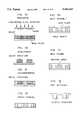
- the LIGA processis schematically illustrated in FIG. 1.
- a polymeric material (resist)which changes its dissolution rate in a liquid solvent (developer) on high energy irradiation, is exposed through an x-ray mask to highly intense parallel x-rays.
- the radiation sourceis an electron synchrotron or an electron storage ring that can generate the highly collimated photon flux in the spectral range required for precise deep-etch x-ray lithography in thick resist layers.
- a pattern thickness between 10 and 1,000 ⁇ mtypically requires an optimal critical wavelength of synchrotron radiation of from 0.1 and 1 nm.
- the resist structureis used as a template in an electroforming process in which metal is deposited onto the electrically conductive substrate (galvanoformation).
- the polymeric resistis then removed to provide a highly precise metal mold.
- the secondary plastic moldis prepared by introducing a polymeric mold material into the metal mold cavities through the holes of a gate plate.
- the platehas a formlocking connection with the polymeric microstructure, and after hardening of the molding resin the plate serves as an electrode in a second electroforming process for generating secondary metallic microstructures.
- the LIGA processproduces highly precise secondary structures, including those with an aspect ratio of up to 100 and minimum lateral dimensions in the micrometer range.
- the LIGA processhas been used to produce microsensors, measuring devices for vibration and acceleration, microoptical devices and symmetry, fluidic devices, and electrical and optical microconnectors.
- Primary disadvantages associated with the LIGA processare that it can only produce fully attached metal structures, and that the process requires the use of an electron syncrotron, that is not readily available.
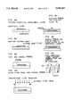
- sacrificial LIGAsacrificial LIGA
- FIG. 2The addition of a sacrificial layer to the LIGA process facilitates the fabrication of fully attached, partially attached or completely free metal structures. Because device thicknesses are typically larger than 10 ⁇ m and smaller than 300 ⁇ m, freestanding structures do not distort geometrically if reasonable strain control of the plated film is achieved. However, the process still requires the use of an electron syncrotron, that is not readily available. It would be useful to provide a process and apparatus for the production of high aspect ratio micro and ministructures for microelectronics that do not require the use of an electron syncrotron.
- Methods and apparatusare disclosed for the production of high precision large scale, micro and mini structures using three dimensional stereolithography.
- the objects formed using these methodshave minimal stress between layers and low curl distortion.
- the objectsalso have low warpage because no post-cure treatment is necessary.
- structuresare prepared using three-dimensional stereolithography under elevated pressure.
- elevated pressureallows the use of elevated temperatures and/or viscous polymeric precursors in the reaction vat.
- the imposed pressure in the vatallows the formation of real objects (as opposed to prototypes) that include inert polymeric or nonpolymeric materials, including magnetic particles, dielectric particles, ceramic particles, liquid crystals, liquid crystal polymers, noncentrosymmetric moieties for nonlinear optics, conductive particles, and conducting polymers, in the solid.
- the magnetic particles, liquid crystals, liquid crystal polymers, and noncentrosymmetric moietiescan be suitably aligned on the imposition of a magnetic or electric field.
- a second embodimentmethods and apparatus are disclosed for the production of high precision large scale, micro and mini structures using three dimensional stereolithography under elevated temperature above ambient temperature. Elevated temperatures lower fluid viscosity so that the polymer precursor fluid flows easily. Elevated temperature can be used in an open or closed vat. When the polymer precursor fluid is heated in a closed vat, an internal vat pressure can be created (depending on the relevant vapor pressure of the precursor fluid) that enhances the precision of the process.
- an improvement in the process of three dimensional stereolithographywherein stress related distortions in the polymeric material are minimized by causing the polymer precursor fluid to polymerize in a differential fashion along a moving front, so that the material ahead of the moving polymer zone remains liquid, and the material that the front has passed is solidified.
- the moving frontis a slit through which UV light is transmitted.
- the moving frontis the radial opening of an iris diaphragm. The still-liquid material ahead of the moving polymer zone can then flow freely, at a rate that equals the rate of shrinkage, and a distortion-free, reduced stress polymeric network is produced.
- the sequential polymerization modification of the three dimensional stereolithographic processcan be performed at ambient pressure, or at elevated pressure or temperature, or at elevated temperature and pressure.
- a biphasic vat solutioncan be used that includes an inert immiscible fluid below the polymer precursor fluid.
- a multi-phasic systemis used, wherein the upper space is a gaseous phase (or light fluid that is UV-transparent but immiscible with the polymer precursor fluid).
- gasinert or reactive
- an intervening fluid layer between the transparent window and the reactive mixtureprevents the sticking of the drawn layer to the window.
- the inert fluidalso prevents the polymer precursor fluid from adversely affecting the means for imposition of pressure.
- Mini and microstructures for microelectronicscan be prepared using the methods disclosed herein that exhibit the precision of structures prepared using the LIGA or SLIGA techniques.
- polymer precursor fluidis sequentially irradiated by a sequentially moving slit system (SMSS) or a computerized iris diaphragm (CID) in a pattern created by a photomask under optional elevated pressure or temperature.
- SMSSsequentially moving slit system
- CIDcomputerized iris diaphragm
- an actuator mechanismraises the layer (which is attached to an elevator platform) by a differential amount, allowing fresh polymer precursor fluid to cover the layer.
- the fresh polymer precursor fluidis then polymerized on top of the prior formed layer in a desired patterned. This process is successively repeated until the desired three dimensional structure is built.
- the high precision plastic moldis completed, it is removed from the vat and electroplated, typically with nickel. The plastic mold is then removed and free metal structure is cast.
- FIG. 1is a cross sectional illustration of an apparatus for high pressure three-dimensional stereolithography.
- FIG. 2is a magnified view of a local region of the monomer/precursor pool during irradiation, using three dimensional stereolithography.
- FIG. 3is a cross sectional illustration of an apparatus for high pressure three-dimensional stereolithography that includes a means for imposition of electric or magnetic fields to align magnetic particles dispersed in the polymeric precursor fluid.
- FIG. 4is a cross sectional illustration of an apparatus for high pressure three-dimensional stereolithography that includes a biphasic vat fluid, and wherein the lower fluid is inert, and the upper fluid is a polymer precursor fluid.
- FIG. 5is a cross sectional illustration of an apparatus for high pressure three-dimensional stereolithography that includes a triphasic vat fluid, that includes a lower fluid that is inert, a next layer of polymer precursor fluid, and an upper gaseous or light fluid phase that is UV-transparent but immiscible with the polymer precursor fluid.
- a triphasic vat fluidthat includes a lower fluid that is inert, a next layer of polymer precursor fluid, and an upper gaseous or light fluid phase that is UV-transparent but immiscible with the polymer precursor fluid.
- FIG. 6is a cross sectional illustration of an apparatus for high pressure three-dimensional stereolithography that includes a triphasic vat fluid, that includes a lower hydraulic fluid that is inert and UV-transparent, a next layer of polymer precursor fluid, and an upper gaseous or light fluid phase that is immiscible with the polymer precursor fluid, and wherein the part is pulled up out of the polymer precursor fluid.
- a triphasic vat fluidthat includes a lower hydraulic fluid that is inert and UV-transparent, a next layer of polymer precursor fluid, and an upper gaseous or light fluid phase that is immiscible with the polymer precursor fluid, and wherein the part is pulled up out of the polymer precursor fluid.
- FIG. 7is a cross-sectional illustration of a method to prepare micro- and ministructures using LIGA technology.
- FIG. 8is a cross-sectional illustration of a method to prepare micro- and ministructures using SLIGA technology.
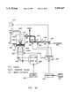
- FIG. 9ais a cross-sectional illustration of an apparatus for the preparation of objects by three-dimensional stereolithography wherein the polymer precursor fluid is sequentially polymerized (V1 is a first valve, V2 is a second valve, SV1 is a first solenoid valve, SV2 is a second solenoid valve, and Q1 is a quick connect).
- FIG. 9bincludes a top view of the apparatus illustrated in FIG. 9a, with additional valve ports for the introduction and removal of desired materials
- FIG. 9cis a side view of the apparatus that illustrates a wiper mechanism.
- FIG. 10is a partial cross-sectional illustration of an apparatus for the production of a three-dimensional object that includes a sequentially moving slit system (SMSS).
- SMSSsequentially moving slit system
- FIG. 11is a partial cross-sectional illustration of an for the production of a three-dimensional object that includes a computerized iris diaphragm (CID).
- CIDcomputerized iris diaphragm
- FIG. 12is a magnified view of a local region of polymer precursor fluid on irradiation by UV light through a sequentially moving slit system.
- FIG. 13is a schematic illustration of an apparatus for efficient release of an object formed by three dimensional stereolithography from the transparent plate to which it becomes attached.
- the transparent plateis etched, and the etched depressions filled with a soft material that has a refractive index that matches the transparent plate.
- a tapeis positioned over the glass plate in such a manner that the adhesive side of the tape is attached to the transparent plate and the nonadhesive side of the tape interfaces with the polymer precursor fluid and the object prepared from it.
- FIG. 14is a cross-sectional schematic illustration of a method to prepare micro- and ministructures for microelectronics using the methods disclosed herein.
- FIG. 15is a schematic illustration of examples of structures that can be prepared using the method of three-dimensional stereolithography disclosed herein.
- FIG. 16is a cross-sectional view of a tapered honeycomb structure that can be generated from a mold prepared according to the methods described herein.
- FIG. 17is a cross-sectional schematic illustration of an apparatus for the production of a three-dimensional object that includes a means for elevating the temperature in the vat.
- ministructurerefers to a structure that is typically greater than approximately 10 microns in height and less than approximately 10 3 microns.
- microstructurerefers to a structure that is typically less than approximately 10 microns in height.
- large scale structurerefers to a structure that is greater than 10 3 microns.
- Methods and apparatusare disclosed for the production of high precision large scale, micro and mini structures using three dimensional stereolithography.
- the methodsinclude the use of elevated pressure, elevated temperature, or sequential polymerization of polymer precursor fluid, or a combination of these, in the three dimensional stereolithographic process.
- a method and apparatusfor the preparation of objects with high precision using three-dimensional stereolithography under elevated pressure, or both elevated pressure and elevated temperature.
- Three-dimensional stereolithography under elevated pressurealso optionally allows the use of viscous polymeric precursors in the reaction vat.
- the use of high temperature in the reaction vatcauses rapid polymerization to close-to-completion stages during greenbody formation, resulting in greatly minimized shrinkage and dimensional alterations accompanying annealing. Since the high pressure process is inherently fast, it can force the reaction of partially polymerized starting materials, or other materials that do not polymerize as easily as acrylates or methacrylates.
- the greenbodycan be prepared from a greater variety of chemicals, with high polymerization rates, and with the ability to crosslink during or after UV exposure at selected spots.
- the use of high pressure in the reaction processalso allows the production of objects that include nonpolymerized materials, such as filler, additives, colloidal particles, magnetic particles and inert polymers.
- the process disclosed hereincan be used to form complex three dimensional magnetic structures such as permanent-magnet structures for the production of transverse helical fields (IEEE Transactions on Magnetics, Vol Mag 22(5), Sep. 1986) and traveling wave tubes that have increased periodic magnetic fields (IEEE Transactions on Magnetics, Vol Mag 25(5), Sep. 1989).
- Typical ethylenically unsaturated monomers that are used in the production of objects by three-dimensional stereolithographyhave a significant vapor pressure at ambient or near ambient temperature.
- the closed reaction vat disclosed hereinprevents evaporation.
- the use of elevated pressure in the vatallows the polymerization reaction to be run at greatly elevated temperatures without inducing boiling or evaporation of the monomer or precursor.
- Photopolymerizationproceeds at an increased rate at elevated temperatures. The high pressure minimizes the amount of shrinkage upon conversion of the monomer to polymer.
- the method for improving the precision of parts made by 3D-stereolithography described herein using increased hydrostatic pressure, or optionally, increased temperatureis not limited to any one type of apparatus, but is instead a general technique.
- a number of apparatuseshave been developed for rapid prototyping using the technique of three dimensional stereolithography.
- Equipmentis sold by, among others, 3D Systems, Inc., Cubital America Inc., Quadrax Laser Technologies, Inc., Light Sculpting, Inc., and DTM Corporation.
- the distortion of objects made with any of these known methods and apparatuses for three-dimensional stereolithographycan be improved by elevating the hydrostatic pressure.
- Systems that function by raising the resin level instead of lowering the modelcan be adapted for use with this process by employing a pressurized gas phase, or by draining or adding inert fluids and introducing the polymerizing fluid.
- FIG. 1is a cross sectional illustration of one example of an apparatus for high precision three-dimensional stereolithography.
- Polymer precursor fluid 10is contained in the reaction vat 12.
- the reaction vatcan have any shape, including four orthogonal sides, as in a rectangular box, or, alternatively, cylindrical.
- a vat with a cylindrical crosssectionmay be a preferred structure due to the high internal pressure.
- a means 14 for elevating the hydrostatic pressure in the vatis attached to the vat.
- Nonlimiting examples of means to elevate the pressureinclude, but are not limited to, a pump, a compressor, such as that used for HPLC or supercritical fluid extraction, a hydraulic pump or piston-cylinder arrangement.
- One side of the reaction vat 12is a window 16 through which a polymeric initiating source 18 is transmitted.
- the initiating source 18typically an ultraviolet radiation laser, writes a pattern in the layer of precursor fluid close to the top surface of the pool.
- the patternis formed by the localized photopolymerization of the pool in selected regions indicated by the laser.
- an actuator mechanism 20lowers the imaged layer that sits on an elevator platform 22 by a differential amount, allowing fresh (unexposed) precursor fluid 10 to cover the underlying written layer. The process is then repeated and a new pattern is thus overlaid.
- Repeated usage of the laser in combination with platform loweringgradually builds up a complex 3-dimensional structure 24 wherein the final part is constructed of successive layers of rigidized images.
- the unreacted fluid 10drains off the part (greenbody).
- Heatingcan be accomplished by standard means, including but not limited to a jacketed vat, immersed coils, IR heating lamps, electrical cartridge heaters, wrapped heating tapes, microwave heaters, or by placing the vat in an oven.
- Shrinkage of local polymerized regions in the objectis minimized using this technique, because as the polymerization occurs, more polymer precursor fluid quickly enters the irradiated area, by virtue of the large hydrostatic pressure in the pool.
- the additional precursor fluidquickly polymerizes in the void space of the irradiated resulting from the shrinkage.
- FIG. 2is a magnified view of a local region of the precursor fluid pool 24 being irradiated by an ultraviolet laser beam 26.
- the shrinkage 28is compensated for by rapid influx of additional polymer precursor fluid 24 under high hydrostatic pressure.
- the resulting greenbody 30does not suffer much shrinkage during annealing because it is already nearly fully polymerized (and in certain cases crosslinked).
- Curl distortionis a complex phenomenon. It is primarily controlled by the rate of stress relaxation at the deposition temperature, and the total residual shrinkage after the newly-formed layer is anchored (attached) to the underlying layer. The use of high temperature ensures rapid polymerization, so that the new layer is nearly completely converted to polymer. Because of this, residual shrinkage is minimized. In addition, stress relaxation increases as temperature increases, and therefore can be reduced appropriately in the object by the careful choice of temperature during manufacture.
- the extent of curing that occurs in the closed vatcan be easily assessed by extracting the uncured material in the object with a suitable solvent, and then comparing the weight and size of the object before and after extraction.
- Methyl ethyl ketoneis a common solvent used for this purpose.
- the temperature in the closed and pressurized vatcan range from ambient temperature or below to any elevated temperature that can be accommodated by the vat and that does not adversely affect the quality of the object, or induce undesired side reactions. Any means known to those of ordinary skill in the art can be used to heat the reaction vat.
- the upper limit on the temperature usedis also influenced by a number of factors, including: (1) the material of construction of the closed vat (as a nonlimiting example, an apparatus made from metal, stainless steel, or alloy, with quartz or sapphire in thick glass as the window can withstand several thousand pounds per square inch pressure and temperature); (2) volatility of the polymer precursor fluid (for example, by using a monomer/polymer mixture, the vapor pressure is lowered, and increased temperatures can be accomplished with less externally applied pressure); and (3) organic decomposition temperatures (oxidative degradation or depolymerization), which are typically relatively high (400° C. or over, with exceptions).
- Typical temperatures for the process described hereinrange from 30° to 300° C., and more typically, between approximately 40° or 50° to 150° C. It is preferred to maintain a uniform temperature throughout the vat to prevent natural convection.
- the optimal working temperature for any given systemcan be determined easily, by carrying out the process at a range of temperatures.
- Superheated liquidcan be used in this process. Care should be taken, however, to avoid oxidation and heat-induced polymerization.
- Any elevated pressurecan be used in the closed vat that decreases the distortion or increases the general quality of the object under production.
- Pressures used in the vatcan range from slightly above ambient pressure, for example, 50-100 psi, to 100,000 psi (pounds per square inch), and more typically, from 50 or 100 psi up to 10,000 psi.
- the increased pressuredecreases the risk of float-away pieces and the need for webbing support, through the ability to use viscous starting materials, and the exploitation of density control with biphasic and multiphasic systems.
- the pressure and temperature relationship governed by monomer boiling or evaporation(which provides the minimum pressure required at a fixed operating temperature) is governed by the well-known Antoine Equation, or in the simplified form, the Clasius-Clapeyron Equation.
- the pressure and temperatureshould be optimized for a given polymer precursor fluid by testing a range of each. For example, if the monomer is not very volatile, high pressure with slightly elevated temperature may be appropriate.
- the transparent windowmust be attached to the container with an adhesive that will withstand the desired high temperature.
- O-ringsor other material that can withstand high pressure, can be used to attach the window.
- a simple pressure pumpcan be connected to the apparatus, as shown in FIG. 1.
- Other nonlimiting examples of means to elevate the pressureinclude, but are not limited to, a compressor, such as that used for HPLC or supercritical fluid extraction, a hydraulic pump and a piston-cylinder arrangement, or a compressed gas source.
- Any polymeric initiating source that can travel through a windowcan be used with this method.
- a preferred initiating sourceis an ultraviolet radiation laser, or UV light from a mercury lamp. The typical wavelength used is between 300 and 400 nm. It is well known that UV lasers can be transmitted through UV transparent windows prepared from quartz, sapphire, or fused silica. Bk7 glass manufactured by Schott is also suitable as a UV transmitting window. Heat can also be used as a polymeric initiating source, according to methods and conditions well known to those of skill in the art.
- Fast curing monomerssuch as acrylate or methacrylate esters are optimal materials for use as the polymer precursor fluid.
- the acrylates or methacrylatescan be monomeric, oligomeric or polymeric, or a mixture thereof. The higher the percentage of acrylate component, the faster the cure in general.
- a number of polymer precursor fluidsare known and commercially available for use in 3D-stereolithography. For example, Ciba Geigy Corporation sells an acrylate based fluid that is used in the apparatus sold by 3D Systems, Inc. DeSoto Chemicals, Inc. also sells an acrylate based material, useful in the apparatus sold by Quadrax Laser Technologies, Inc.
- Somos 2100 photopolymersold by the Du Pont/Somos Venture, is a precursor fluid that contains acrylates as a minor component.
- Another suitable materialis Potting Compound 363, a modified acrylate sold by Locktite Corporation.
- UV curable resinsare also taught in U.S. Pat. No. 4,100,141, and 4,942,001. Other UV-curable coatings, varnishes, and adhesives are well known to those skilled in the art.
- thermosetting precursor fluidsuch as that of free methacrylate or acrylate monomer
- Thermosetting networksare typically highly crosslinked. Examples include UV-curable epoxies, multifunctional acrylates, and polyunsaturated polymers.
- the use of thermosetting precursor fluidresults in a green body with substantially decreased distortion, on the basis that the higher the existing degree of crosslinking at the moment of formation and deposition of the greenbody, the lower the residual distortion upon annealing.
- Polymer precursor fluidsshould cure fast enough under the conditions of use that a solid or suitably semisolid layer is formed on initiation.
- the conditions of elevated pressure and, optionally, elevated temperature, used in the method described hereinallow for the use of precursor fluids that previously could not have been used due to unacceptably slow polymerization times, including styrenics and allyl-terminated monomers.
- Acrylate-terminated or otherwise unsaturated urethanes, carbonates, and epoxiescan also be used in the rigid framework.
- An example of an unsaturated carbonateis allyl diglycol carbonate (CR-39).
- Unsaturated epoxies that can be usedinclude, but are not limited to, glycidyl acrylate, glycidyl methacrylate, allyl glycidyl ether, and 1,2-epoxy-3-allyl propane.
- N-vinyl monomersincluding N-vinyl pyrrolidine, bisphenol-A-bis-2-hydroxypropylmethacrylate, bisphenol-A-bis-2-hydroxypropylacrylate, bisphenol-A-ethoxy diacrylate, tri- or tetrafunctional acrylates or methacrylates, alkylene glycol and polyalkylene glycol diacrylates and methacrylates, including ethylene glycol dimethacrylate and ethylene glycol diacrylate, propoxylated neopentyl glycol diacrylate, vinyl or allyl acrylates or methacrylates, divinylbenzene, diallyldiglycol dicarbonate, diallyl maleate, diallyl fumarate, diallyl itaconate, vinyl esters such as divinyl oxalate, divinyl malonate, diallyl succinate, triallyl isocyanurate, the dime
- Preformed polymers that have ethylenically unsaturated groupscan also be used in the precursor polymer fluid, including acrylate-terminated novolacs, and polyurethanes, polymeric epoxies, and polycarbonates that have been derivatized to include acrylate, methacrylate, or other unsaturated functional groups. These types of polymers are well known and commercially available.
- photocurable materialsexamples include the line of Synocure products sold by Cray Valley Products (for example, Synocure 3101, a diacrylate derivative of bisphenol-A, and Synocure 3134, an aliphatic urethane diacrylate), and the Epon products sold by Shell Corporation (for example, Epon 1001 and Epon 828, which are both diacrylates of the diglycidyl ether of bisphenol-A). Vinyl-terminated liquid crystalline polymers can also be used.
- inert polymerscan be added to the starting mixture, to thicken the mixture, for ease of handling, to reduce the total reaction time, or for other reasons.
- the typical range of inert materialis in the range of 1% to 90% by weight of the polymer precursor fluid.
- the inert polymeric materialcan be any polymer, and can be used in any amount, that does not adversely affect the desired properties of the final material.
- Inert polymersin general are polymers that do not react with other components in the reaction solution.
- an inert polymer of the monomer present in the polymer precursor fluidis added to the fluid. For example, if methyl methacrylate is in the polymer precursor fluid, polymethylmethacrylate can be added to the solution.
- inert polymeris included in the polymer precursor fluid in the form of a latex or dispersion.
- the latexcan optionally be a composite or multi-phase material, composed, for example, of a core-shell structure.
- the inert polymercan contribute a beneficial property to the solidified object.
- a latex of rubbery particlesincluding but not limited to poly(styrene-butadiene) rubber, can be added to improve the impact resistance of an object formed from hard monomers.
- a dispersion of hard particlessuch as poly(styrene) or poly(methyl methacrylate)
- Latexes or dispersionswith any desired average particle size, typically from 100 nm to 10 ⁇ M, can be included in the fluid. The optimal average particle size and average particle size distribution will depend on the specific system and the desired property modifications. Impact resistance is usually enhanced most efficiently with particles of average particle size less than one micron.
- Nonpolymeric fillerscan also be added to the polymer precursor fluid, including but not limited to carbonates, such as CaCO 3 and MgCO 3 , clay, including attapulgite clay, borates, sulfates, phosphates, diatomaceous earth such as celite and silica flour, alumina, colloidal silica, and zeolite solids. Filler can be added up to the volume fraction at which the mixture stops flowing no matter what pressure is applied. Typically, there is a 64% theoretical monodisperse sphere packing maximum.
- Colloidal particles suspended by Brownian motioncan be used, including colloidal gold, titanium oxide, ferric oxides (magnetic), cobalt, molybdenum oxide, vanadium oxide, nickel, alloys, transition metal-rare earth complexes, silicon dioxide, silicon nitride, germanium oxide, silicon atom clusters, gallium arsenide, and other semiconducting particles.
- Organic particlescan be crosslinked beads (as small as colloids or as large as micron sized spheres). Since most organic materials are of comparable density, large organic particles can easily be dispersed throughout the fluid without settling.
- magnetic particlescan be included in the polymer precursor solution.
- Nonlimiting examplesinclude the magnetic particles mentioned above, including ferric oxide and transition metal/rare earth compounds in small particle form.
- the N-S polecan be aligned, and the resin then hardened, in such a way that tiny magnetized regions are formed, for example, tiny motors, actuators, and sensors.
- Complex keys and lockscan be formed using this procedure.
- a lockreads the code by induced currents in coils. After one turn of the key, the embedded information is read.
- Liquid crystal moleculesfor example, ferroelectrics, cholesterics, nematics (nematogens), smetics, etc.
- liquid crystal like molecules or aggregatescan be aligned and trapped in resin for display or light piping applications.
- Nonlinear optically active compoundssuch as noncentrosymmetric molecules or block polymers, graft polymers, or copolymers can be frozen in a controlled way 3-dimensionally, allowing very complex integrated optics to be prepared, with horizontal as well as vertical light-piping and light modulation capabilities.
- FIG. 3is an illustration of one apparatus for high pressure three-dimensional stereolithography that includes a means for imposition of electric or magnetic fields to align magnetic particles dispersed in the polymeric precursor fluid.
- Polymer precursor fluid 32 that contains magnetic particles or ferroelectric liquid crystalsis irradiated with an ultraviolet laser beam 34 between electrodes or magnets 36 and 38 to provide an object 40 that sits on platform 42.
- Hydrostatic pressureis imposed by means of pump 44, and elevated temperature is provided by heating means 46.
- the upper limit of the electric fieldis the breakdown strength of the fluid, typically in the range of 1 MV/cm.
- the upper limit of the magnetic fieldis the limit of the available electromagnet. Large electromagnets such as those used in nuclear magnetic resonance can provide a very strong magnetic field.
- the fieldcan be pulsed in a controlled fashion or reversed as desired. It can also be crossed or rotated.
- the resulting objectcan have regions that are magnetized and regions that are not magnetized.
- the electric or magnetic fieldcan be imposed in a horizontal fashion as well as in a verticle fashion.
- the particles in the objectcan be aligned differently, depending on when the field is turned on or off or reversed.
- this techniquecan be used to produce real parts, not just models or prototypes. In addition, it can produce parts that serve active functions, such as motion control and light guiding.
- an immiscible fluidin another alternative embodiment, can be used in the high pressure vat to conserve polymer precursor fluid and to function as hydraulic fluid for system pressurization.
- the inert materialis typically at the bottom of the vat, as illustrated in FIGS. 4 and 5.
- the inert materialshould be immiscible with the UV curable material, and have an intermediate density between the uncured and cured UV-curable material. Upon curing, the cured fluid (now a polymer), becomes heavier (denser) than the inert material. Since the laser is typically focused through a quartz or sapphire window on top of the closed and pressurized vessel, the inert material does not have to be UV transparent. A membrane separating the two fluids, such as that disclosed in U.S. Pat. No. 5,011,635, is not necessary in this system. If the inert material is transparent, the UV irradiation can shine up from the bottom of the vat, as illustrated in FIG. 6.
- Silicones and fluoromersare ideal candidates for the inert fluid.
- the density of these materialsis greater than monomers or precursors of polymers, but lower than dead polymer (finished polymers).
- the buoyancy effect experienced by the part as it descends into the inert fluidkeeps it from deforming (sagging) under gravity.
- Nonlimiting examplesare perfluorinated alkanes and PFA.
- Fluorofluidsare sold by E. I. Du Pont de Nemours and Company and Minnesota Mining and Manufacturing Company.
- Silicone fluidsinclude polydimethylsiloxane oligomers, and aromatic and aliphatic siloxanes. Huls Corporation manufactures a complete line of silicone fluids.
- the inert fluidcan also be water, glycerol, glycol, alcohol or fluorinated derivatives of these liquids.
- the inert fluidserves at least three additional important functions: it scrubs the greenbody of excess material (unpolymerized material clinging to the greenbody), it transmits the high imposed pressure, and it physically separates the pump from the polymer precursor fluid. Since the vat may be under elevated pressure due to a duct work attached to the vessel, the duct can be physically separated from the polymer precursor material, preventing clogging. If UV-curable fluid is in the pump duct, even stray light may trigger enough undesirable polymerization to clog the opening.
- FIG. 4is a cross sectional illustration of one type of apparatus for high pressure three-dimensional stereolithography that includes a biphasic vat fluid.
- Polymer precursor fluid 48floats above the inert fluid 50 in the pressurized reaction vat 52.
- a means 54 for elevating the hydrostatic pressure in the vat, typically a pump,is attached to the vat below the interface of the two fluids 56.
- the polymer initiating source 58is transmitted through a window 60.
- the initiating source 58typically an ultraviolet radiation laser, writes a pattern in the layer of precursor fluid close to the top surface of the pool.
- an actuator mechanism 62lowers the imaged polymerized layer (which now has a density that is higher than the inert fluid) into the inert fluid 50.
- Fresh (unexposed) precursor fluid 52is then floated on top of the imaged layer at the interface of the two fluids. The process is then repeated and a new pattern is thus overlaid.
- Repeated usage of the laser in combination with platform loweringgradually builds up a complex 3-dimensional structure 64 on platform 66 wherein the final part is constructed of successive layers of rigidized images, and is submerged in the inert fluid 50.
- the inert fluid 50scrubs the unreacted fluid 48 drains off the part (greenbody).
- polymer precursor fluid, inert fluid and gas or light fluidare added and removed as desired through appropriately placed ducts in the apparatus, not illustrated.
- FIG. 5is a cross sectional illustration of an apparatus for high pressure three-dimensional stereolithography that includes a triphasic vat fluid, that includes a lower fluid that is inert, a next layer of polymer precursor fluid 70, and an upper gaseous or light fluid phase 72 that is UV-transparent but immiscible with the polymer precursor fluid.
- a means 74 for elevating the hydrostatic pressure in the vattypically a pump, is attached to the vat below the polymer precursor fluid 70.
- the polymer initiating source 76is transmitted through a window 78.
- the initiating source 76typically an ultraviolet radiation laser, writes a pattern in the layer of precursor fluid close to the top surface of the pool.
- an actuator mechanism 80lowers the imaged polymerized layer (which now has a density that is higher than the inert fluid) into the inert fluid 68.
- Fresh (unexposed) precursor fluid 70is then floated on top of the imaged layer at the interface of the two fluids. The process is then repeated and a new pattern is thus overlaid.
- Repeated usage of the laser in combination with platform loweringgradually builds up a complex 3-dimensional structure 82 on platform 84 wherein the final part is constructed of successive layers of rigidized images, and is submerged in the inert fluid 68.
- the inert fluid 68scrubs the unreacted fluid 70 drains off the part (greenbody).
- FIG. 6is a cross sectional illustration of an apparatus for high pressure three-dimensional stereolithography that includes a triphasic vat fluid, that includes a lower hydraulic fluid 88 that is inert and UV-transparent, a next layer of polymer precursor fluid 90, and an upper gaseous or light fluid phase 92 that is immiscible with the polymer precursor fluid, and wherein the part is pulled up out of the polymer precursor fluid.
- a means 94 for elevating the hydrostatic pressure in the vattypically a pump, is attached to the vat below the polymer precursor fluid 90.
- the polymer initiating source 96is transmitted through a window 98.
- the initiating source 96typically an ultraviolet radiation laser, writes a pattern in the layer of precursor fluid close to the bottom surface of the pool on platform 104.
- an actuator mechanism 100raises the imaged polymerized layer.
- Fresh (unexposed) precursor fluid 90is then floated on top of the imaged layer at the interface of the two fluids. The process is then repeated and a new pattern is thus overlaid. Repeated usage of the laser in combination with platform raising gradually builds up a complex 3-dimensional structure 102 on platform 104.
- Elevated temperatureslower fluid viscosity so that the polymer precursor fluid flows easily. Elevated temperature can be used in an open or closed vat. When the polymer precursor fluid is heated in a closed vat, an internal vat pressure can be created (which depends on the relevant vapor pressure of the precursor fluid) that enhances the precision of the process. If the polymer precursor fluid has a high vapor pressure, a significant increase in vat pressure can be accomplished by increasing the temperature of the vat to approximately equal to or above that of the boiling point of the fluid. If the polymer precursor fluid has a low vapor pressure, elevated temperature can be used to increase the pressure in the vat by completely or almost completely filling the vat with the polymer precursor liquid. The increase in temperature causes a significant rise in pressure due to the thermal expansion of the liquid.
- a preferred meansis a full jacket heater, such as that sold by Thermofoil Heater Products, Inc., Minneapolis, Minn.
- FIG. 17is a cross-sectional schematic illustration of one embodiment of an apparatus for the production of a three-dimensional object that includes a means for elevating the temperature in the vat.
- heating means 320is interfaced with control box 130 that receives heating instructions from computer 120.
- control box 130that receives heating instructions from computer 120.
- the reaction vat filled to the appropriate level with polymer precursor fluidis stabilized at the desired temperature, and the stereolithographic process then initiated.
- the temperature in the vatcan range from ambient temperature or below to any elevated temperature that can be accommodated by the vat and that does not adversely affect the quality of the object, or induce undesired side reactions.
- a temperature of between slightly above ambient temperature to approximately 300° C.is suitable, and more typically, between 40° or 50° C. and 150° C.
- a temperatureshould be selected that minimizes the distortion of the object to be formed, with the realization that as the object cools, it will typically undergo a degree of shrinkage. The shrinkage can cause stress in the object, resulting in a lack of accuracy, or precision.
- the degree of shrinkageis a function of a number of factors, including but not limited to the nature of the polymer precursor fluid, the extent of unpolymerized material in the object, the shape of the object, and whether pressure was used in the process.
- the optimal working temperature for any given systemcan be determined easily, by carrying out the process at a range of temperatures and conditions.
- large scale, mini, and microstructuresare prepared by three dimensional stereolithography in which the polymer precursor fluid is polymerized sequentially to reduce structure distortion caused by stress within and between layers.
- This methodreduces curl distortion during the polymerization process.
- the sequential polymerization modification of the three dimensional stereolithographic processcan be carried out at ambient temperature and pressure, or at elevated pressure, elevated temperature, or elevated pressure and temperature.
- the parameters and reaction conditions described in Section I.apply to the method disclosed in Section II., including when performed under ambient conditions.
- the sequential polymerization techniqueis taught in general in U.S. Pat. Nos. 5,110,514 and 5,114,632 filed by David S. Soane.
- the sequential polymerization methodminimizes stress and cavitation, or voids caused by the shrinkage of material during polymerization, that would otherwise cause locked-in stress and decrease replication fidelity. Stress in local polymerized regions of the object is minimized using this technique, because as the polymerization occurs sequentially within each layer, more polymer precursor fluid quickly enters the irradiated area to replenish the instantaneous volume lost to polymerization induced shrinkage. Even though the flow may be microscopic in quantity, the effect is profound, as intra and inter layer stress are minimized or eliminated.
- the additional polymer precursor fluidquickly polymerizes in the void space of the irradiated region resulting from shrinkage. This is illustrated in FIG. 12, which provides a magnified view of a local region of the precursor fluid pool being irradiated by a UV mercury lamp.
- the sequential polymerization processis easily adapted to either radiation or thermal curing. Radiation curing is preferred because it is more controllable, and in general requires a shorter cure time. Radiation curing can be performed at moderately elevated temperatures to further reduce polymerization time.
- a moving front of polymerization initiating sourcecan be accomplished by use of any appropriate means.
- a sequentially moving slit system(SMSS) is used, wherein a thin slit (typically between 1 ⁇ m and 10 mm) of irradiation sequentially passes over the polymer precursor fluid in such a manner that the material ahead of the moving polymer zone remains liquid, and the material that the front has passed is solidified.
- the moving frontis the radial opening of an iris diaphragm. The still-liquid material ahead of the moving polymer zone flows freely, at a rate that equals the rate of shrinkage, and a distortion-free, reduced stress polymeric network is produced.
- FIG. 9ais a schematic cross-sectional illustration of one apparatus for the preparation of objects by three-dimensional stereolithography wherein the polymer precursor fluid is sequentially polymerized (V1 is a first valve, V2 is a second valve, SV1 is a first solenoid valve, SV2 is a second solenoid valve, and Q1 and Q2 are quick connects).
- V1is a first valve
- V2is a second valve
- SV1is a first solenoid valve
- SV2is a second solenoid valve
- Q1 and Q2are quick connects
- data 110is fed into a computer 120 to establish a CAD file for the desired object, which is converted mathematically into stacked cross-sections, or layers.
- the computer 120interfaces with control box 130 that controls the operation of solenoid valve 160, solenoid valve 170, a stepping motor 270, and an electronic shutter 220.
- Second solenoid valve 170allows the release of pressure from the system as desired.
- Inert gasis fed through tube 155 (which has a quick connect joint 190, through valve 150 and solenoid valve 160, past quick connect 170 into reaction vat 205.
- An elevator 260 controlled by stepping motor 270is connected to platform 215.
- a thin layer of polymer precursor fluid 235is introduced into the reaction vat 205 between platform 215 and UV transparent window 200 from tube 140 past valve 145.
- Valve 145can be interfaced with computer 120 through control box 130 as desired.
- Power supply 250feeds the UV lamp 230.
- the power of the UV lamptypically ranges from hundreds to thousands of Watts.
- UV light from UV lamp 230is reflected off mirror 240 through electronic shutter 220.
- the UV lightis then passed sequentially through a photomask to the thin layer of polymer precursor fluid.
- the means for moving the light sequentially 245is located at any appropriate place between the point at which the UV light is reflected off of the mirror, and the photomask 210. Two examples of means for sequential light movement, the sequentially moving slit system, and the iris diaphragm, are illustrated in detail in FIGS. 10 and 11.
- the photomaskis located at a point between the means for sequential light movement 245, and the polymer precursor fluid 235, and preferably, between the electronic shutter 220 and the transparent window 200.
- Any photomask system known to those skilled in the artcan be used in this apparatus.
- U.S. Pat. Nos. 5,157,423 and 5,139,338disclose a photomask system in which a CAD slice of an object is transferred from the computer to a mask generator, which operates like a photocopier: a negative image of the cross section is produced on a glass mask plate by charging portions of the surface and "developing" the electrostatic image with toner powder.
- negative slice imagesare transmitted directly to the polymer surface using a flat array of backlighted liquid crystals under individual control.
- the use of a sequentially moving slit systemallows the "dot matrix" type of programmable mask to be adopted.
- the photomaskcan be achieved by pixel reflectors actuated by piezoelectricity, as tiny deflections are sufficient to darken/lighten the intended spots.
- the sequential polymerizationprogresses, the slit-like mask is synchronously altered by simultaneously switching on and off the in-line pixels.
- microbubble technology used in ink-jet printingis used to create the photomask.
- Microelectrodescan be positioned in a liquid filled cylinder, and light passed through the cylinder while the electrodes are heated. Upon transient heating, bubbles form at selected sites, and diffuse light travels through the cylindrical lens. The bubble spots correspond to dark, or unfocused pixels. The combination of dark and light spots forms the photomask image.
- UV lightis passed through the photomask 210 sequentially to create the appropriate light pattern on the thin polymer precursor layer to provide a polymeric layer of desired shape.
- the elevator 260moves the imaged layer that sits on elevator platform 215 by a differential amount, allowing fresh (unexposed) precursor fluid to cover the underlying written layer.
- the processis then successively repeated and new patterns overlaid, until a complex 3-dimensional structure is provided that is constructed of the successive layers of rigidized images.
- the polymer precursor fluidcan be provided as a very thin layer, alone or over an inert immiscible layer.
- the methodhas the advantage of limiting layer thickness directly rather than relying solely upon UV damping due to absorption to limit the depth of curing.
- an ultra thin laminaeis provided.
- the ability to produce an ultra-thin laminaedepends on the viscosity of the polymer precursor fluid and its tendency to spread out between the transparent window and the elevator platform.
- the use of elevated pressure and elevated temperature in the processlowers the viscosity of the polymeric precursor fluid, facilitating this process.
- objectscan be prepared that include layers that vary in physical properties.
- the first several polymeric layerscan be constructed of a soft, impact-resistant material, and successive layers formed from a hard thermoplastic material.
- FIG. 9bis a top view of the apparatus illustrated in FIG. 9a, with additional valve ports for the introduction and removal of varying polymer precursor fluids, and a side view of the apparatus that illustrates a means for vacuum removal of the remaining polymer precursor fluid from the transparent plate.
- This apparatus embodimentcan be used to prepare three dimensional objects from layers of differing polymer precursor fluids.
- control box 130signals the opening of the desired valve (V1 and V3 through Vn) to provide a layer of first polymer precursor fluid between the transparent plate and the platform.
- the IR sensorsends a signal to the control box to close the valve when a desired fluid thickness has been achieved.
- the platformis then lowered to the fluid surface, and the fluid cured in the desired pattern.
- the platformis then moved an appropriate distance, and the vacuum wiper transverses the transparent plate to remove residual fluid.
- FIG. 10is a partial cross-sectional illustration of an apparatus for the production of a three-dimensional object that includes a sequentially moving slit system (SMSS).
- the apparatusincludes a movable and adjustable slit 280, a stepping motor 290 to control the speed of slit movement, an electric shutter 220, and a control box 130 that interfaces the stepping motor 290 and other programmable pieces, as described above in FIG. 9, to a computer.
- the slit sizecan be varied according to the type of polymer precursor fluid used.
- the moving speed of the UV light slitis dictated by the curing time of the polymer precursor fluid, typically between 2 and 30 seconds.
- the electronic shutter 220opens, and the slit starts moving from one side of the photomask 210 to the other side.
- the electronic shutteris closed.
- the elevator 260moves the imaged layer that sits on elevator platform 215 by a differential amount, allowing fresh (unexposed) precursor fluid to cover the underlying written layer.
- FIG. 11is a partial cross-sectional illustration of an apparatus for the production of a three-dimensional object in which sequential polymerization is accomplished with a computerized iris diaphragm (CID).
- the apparatusincludes an iris diaphragm 300, a computer controlled rotation stage 310, an electronic shutter 220, and a control box 130 that interfaces the rotation stage 310, electronic shutter 220, and other programmable pieces, as indicated in FIG. 9, to a computer.
- the iris diaphragmis useful for the smooth control of a radially expanding or contracting beam of radiation, while keeping the energy per unit area constant.
- the rotational stageis used to rotate the iris diaphragm, if the iris diaphragm is not automated.
- the electronic shutteris opened first, and then the iris diaphragm is opened at a desired rate. After completion of cure, the electronic shutter is closed. The process is then repeated until the three dimensional object is constructed.
- FIG. 13is a schematic illustration of an apparatus for efficient release of an object formed by three dimensional stereolithography from the transparent plate to which it may become attached.
- the transparent plateis modified to have rises and depressions, and the depressions are filled with a soft material that has a refractive index that matches that of the transparent plate, or alternatively, are filled with air.
- FIG. 13provides illustrations of two types of modified transparent plate surfaces, a grid surface and a dotted surface. Other patterns can also be used to modify the surface as desired.
- a tape that has an adhesive side and a nonadhesive sideis positioned over the glass plate in such a manner that the adhesive side of the tape is attached to the modified surface of the transparent plate and the nonadhesive side of the tape interfaces with the polymer precursor fluid and the object prepared from the fluid.
- the objectWhen the object has been completed, it can easily be separated from the nonadhesive tape surface, that is flexible due to the cushioned effect of the soft filling or air in the modified transparent plate.
- Teflon-FEPTeflon-FEP
- One side of the Teflon-FEP filmhas a pressure sensitive adhesive, so that it is easy to apply to the plate. The elastic deformation of the soft material triggers vacuum release.
- CHR Inc.sells Teflon-FEP under the catalog name "C", and also sells other suitable transparent polyester tapes, including M52, M60, M69, and M56.
- micro and ministructurescan be prepared that are suitable for microelectronic applications.
- specific structuresthat can be made using these techniques include magnetic micromotors, toroidal transformers, metal flexure actuators, pressure transducers, microturbines, and intermeshing microcoils.
- Mini and microstructures for microelectronicscan be prepared using the methods disclosed herein that exhibit the precision of structures prepared using the LIGA or SLIGA techniques. As illustrated in FIG. 14, after a high precision plastic mold is completed, it is removed from the vat and electroplated, typically with nickel. The plastic mold is then removed and free metal structure is cast.
- FIG. 9is an illustration of complex structures that can be prepared using this technique, including half domes, cones and pyramids. As the number of layers used to build the structure increases, the smoothness of the surface increases.
- FIG. 16is an illustration of a tapered honeycomb shape that can be built using this process. The tapered honeycomb is useful in the area of bio-separation.
- the mold building process disclosed hereinrepresents a significant improvement over the LIGA and SLIGA techniques, in that 1) there is no need for x-ray irradiation; 2) no alignment is required (in SLIGA, the x-ray mask must be geometrically aligned to the patterned sacrificial layer and the processed substrate); 3) mold building time is reduced dramatically; 4) the mold design is simplified due to automatic photomask generation by CAD; 6) there is no structural height limit; and 7) the mold can have complex sidewall profiles and can be made of several materials in successive layers.
Landscapes
- Chemical & Material Sciences (AREA)
- Engineering & Computer Science (AREA)
- Materials Engineering (AREA)
- Manufacturing & Machinery (AREA)
- Mechanical Engineering (AREA)
- Physics & Mathematics (AREA)
- Optics & Photonics (AREA)
- Composite Materials (AREA)
Abstract
Description
Claims (7)
Priority Applications (1)
| Application Number | Priority Date | Filing Date | Title |
|---|---|---|---|
| US08/068,692US5545367A (en) | 1992-04-15 | 1993-05-27 | Rapid prototype three dimensional stereolithography |
Applications Claiming Priority (5)
| Application Number | Priority Date | Filing Date | Title |
|---|---|---|---|
| US86948092A | 1992-04-15 | 1992-04-15 | |
| WOPCT/US93/03544 | 1993-04-15 | ||
| PCT/US1993/003544WO1993020993A1 (en) | 1992-04-15 | 1993-04-15 | Rapid prototype three-dimensional stereolithography |
| US5912893A | 1993-05-07 | 1993-05-07 | |
| US08/068,692US5545367A (en) | 1992-04-15 | 1993-05-27 | Rapid prototype three dimensional stereolithography |
Related Parent Applications (2)
| Application Number | Title | Priority Date | Filing Date |
|---|---|---|---|
| US86948092AContinuation-In-Part | 1992-04-15 | 1992-04-15 | |
| US5912893AContinuation-In-Part | 1992-04-15 | 1993-05-07 |
Publications (1)
| Publication Number | Publication Date |
|---|---|
| US5545367Atrue US5545367A (en) | 1996-08-13 |
Family
ID=27369588
Family Applications (1)
| Application Number | Title | Priority Date | Filing Date |
|---|---|---|---|
| US08/068,692Expired - Fee RelatedUS5545367A (en) | 1992-04-15 | 1993-05-27 | Rapid prototype three dimensional stereolithography |
Country Status (1)
| Country | Link |
|---|---|
| US (1) | US5545367A (en) |
Cited By (248)
| Publication number | Priority date | Publication date | Assignee | Title |
|---|---|---|---|---|
| US5672225A (en)* | 1995-07-27 | 1997-09-30 | Cowan; John R. | Method for engraving three dimensional images |
| US5785919A (en)* | 1994-06-30 | 1998-07-28 | Short Brothers Plc | Method of manufacture of structual cellular components |
| US5866058A (en)* | 1997-05-29 | 1999-02-02 | Stratasys Inc. | Method for rapid prototyping of solid models |
| US5976339A (en)* | 1993-10-01 | 1999-11-02 | Andre, Sr.; Larry Edward | Method of incremental layered object fabrication |
| US5989679A (en)* | 1995-06-14 | 1999-11-23 | United Technologies Corporation | Strong, dimensionally stable object |
| US6036910A (en)* | 1996-09-25 | 2000-03-14 | Teijin Seiki Co., Ltd. | Three-dimensional object by optical stereography and resin composition containing colorant for producing the same |
| US6051179A (en)* | 1997-03-19 | 2000-04-18 | Replicator Systems, Inc. | Apparatus and method for production of three-dimensional models by spatial light modulator |
| US6116888A (en)* | 1998-07-29 | 2000-09-12 | Owens-Brockway Plastic Products Inc. | Prototype mold for blow-molding hollow plastic containers and method of making same |
| US6117385A (en)* | 1997-08-06 | 2000-09-12 | The University Of Dayton | Method and apparatus for stereolithography |
| US6129559A (en)* | 1996-01-19 | 2000-10-10 | Sumitomo Electric Industries, Ltd. | Microconnector and method of manufacturing the same |
| US6153034A (en)* | 1997-08-03 | 2000-11-28 | Micromod R.P. Ltd | Rapid prototyping |
| US6200646B1 (en) | 1999-08-25 | 2001-03-13 | Spectra Group Limited, Inc. | Method for forming polymeric patterns, relief images and colored polymeric bodies using digital light processing technology |
| US6243616B1 (en)* | 1997-06-30 | 2001-06-05 | Huels Aktiengesellschaft | Method and device for producing three-dimensional objects |
| US6334960B1 (en)* | 1999-03-11 | 2002-01-01 | Board Of Regents, The University Of Texas System | Step and flash imprint lithography |
| US6409902B1 (en) | 1999-08-06 | 2002-06-25 | New Jersey Institute Of Technology | Rapid production of engineering tools and hollow bodies by integration of electroforming and solid freeform fabrication |
| US6423260B1 (en) | 1997-08-06 | 2002-07-23 | University Of Dayton | Methods and apparatus for producing ordered parts from liquid crystal monomers |
| US20020105074A1 (en)* | 2000-06-08 | 2002-08-08 | Salman Akram | Collar positionable about a periphery of a contact pad and around a conductive structure secured to the contact pads, semiconductor device components including same, and methods for fabricating same |
| US20020104826A1 (en)* | 1998-08-18 | 2002-08-08 | Claes Blom | Metallic building element for optoelectronics |
| US6468891B2 (en) | 2000-02-24 | 2002-10-22 | Micron Technology, Inc. | Stereolithographically fabricated conductive elements, semiconductor device components and assemblies including such conductive elements, and methods |
| US20020195748A1 (en)* | 2000-08-29 | 2002-12-26 | Farnworth Warren M. | Layer thickness control for stereolithography utilizing variable liquid elevation and laser focal length |
| US6500378B1 (en) | 2000-07-13 | 2002-12-31 | Eom Technologies, L.L.C. | Method and apparatus for creating three-dimensional objects by cross-sectional lithography |
| US20030003180A1 (en)* | 2000-08-08 | 2003-01-02 | Farnworth Warren M. | Surface smoothing of stereolithographically formed 3-D objects |
| US20030004657A1 (en)* | 2001-06-08 | 2003-01-02 | Mark Allen | Digital clay apparatus and method |
| US6506671B1 (en) | 2000-06-08 | 2003-01-14 | Micron Technology, Inc. | Ring positionable about a periphery of a contact pad, semiconductor device components including same, and methods for positioning the ring around a contact pad |
| US6524346B1 (en)* | 1999-02-26 | 2003-02-25 | Micron Technology, Inc. | Stereolithographic method for applying materials to electronic component substrates and resulting structures |
| US20030046177A1 (en)* | 2001-09-05 | 2003-03-06 | Graham Winchester | 3-dimensional imaging service |
| US6554600B1 (en)* | 1998-10-09 | 2003-04-29 | Eos Gmbh Electro Optical Systems | Device for producing a three-dimensional object, especially a laser sintering machine |
| US20030087200A1 (en)* | 2001-11-06 | 2003-05-08 | Eastman Kodak Company | Technique for making deep mircostructures in photoresist |
| US6561208B1 (en) | 2000-04-14 | 2003-05-13 | Nanostream, Inc. | Fluidic impedances in microfluidic system |
| US20030121602A1 (en)* | 2002-01-02 | 2003-07-03 | George Hsieh | Attaching components to a printed circuit card |
| US20030133358A1 (en)* | 2002-01-11 | 2003-07-17 | Nanostream, Inc. | Multi-stream microfluidic aperture mixers |
| US6603444B1 (en)* | 1999-06-16 | 2003-08-05 | Canon Kabushiki Kaisha | Display element and display device having it |
| US6627835B1 (en) | 2000-02-02 | 2003-09-30 | Purdue Research Foundation | Three dimensional object fabrication techniques |
| US6630093B1 (en) | 1999-08-21 | 2003-10-07 | Ronald D. Jones | Method for making freeform-fabricated core composite articles |
| US20030194503A1 (en)* | 2002-04-16 | 2003-10-16 | Schleier-Smith Johann M. | Robotic manipulation system utilizing fluidic patterning |
| US20030198130A1 (en)* | 2000-08-07 | 2003-10-23 | Nanostream, Inc. | Fluidic mixer in microfluidic system |
| US6647308B1 (en) | 1997-07-29 | 2003-11-11 | Ronald Martin Prejean | Key manufacturing method |
| US20040007799A1 (en)* | 2002-07-11 | 2004-01-15 | Choi Byung Jin | Formation of discontinuous films during an imprint lithography process |
| US20040013982A1 (en)* | 1999-09-14 | 2004-01-22 | Massachusetts Institute Of Technology | Fabrication of finely featured devices by liquid embossing |
| US20040020367A1 (en)* | 2001-10-19 | 2004-02-05 | Soane David S. | Anti-pathogenic air filtration media and air handling devices having protective capabilities against infectious airborne microorganisms |
| US6696220B2 (en) | 2000-10-12 | 2004-02-24 | Board Of Regents, The University Of Texas System | Template for room temperature, low pressure micro-and nano-imprint lithography |
| US20040065252A1 (en)* | 2002-10-04 | 2004-04-08 | Sreenivasan Sidlgata V. | Method of forming a layer on a substrate to facilitate fabrication of metrology standards |
| US6727035B2 (en) | 1998-02-18 | 2004-04-27 | Dsm N.V. | Photocurable liquid resin composition |
| US20040151978A1 (en)* | 2003-01-30 | 2004-08-05 | Huang Wen C. | Method and apparatus for direct-write of functional materials with a controlled orientation |
| US20040163563A1 (en)* | 2000-07-16 | 2004-08-26 | The Board Of Regents, The University Of Texas System | Imprint lithography template having a mold to compensate for material changes of an underlying liquid |
| US20040200411A1 (en)* | 2002-05-16 | 2004-10-14 | The Board Of Regents, The University Of Texas System | Apparatus for fabricating nanoscale patterns in light curable compositions using an electric field |
| US20050051698A1 (en)* | 2002-07-08 | 2005-03-10 | Molecular Imprints, Inc. | Conforming template for patterning liquids disposed on substrates |
| US20050058837A1 (en)* | 2003-09-16 | 2005-03-17 | Farnworth Warren M. | Processes for facilitating removal of stereolithographically fabricated objects from platens of stereolithographic fabrication equipment, object release elements for effecting such processes, systems and fabrication processes employing the object release elements, and objects which have been fabricated using the object release elements |
| RU2248635C2 (en)* | 2002-11-27 | 2005-03-20 | Зайцев Сергей Иванович | Collimator manufacturing process |
| US20050064344A1 (en)* | 2003-09-18 | 2005-03-24 | University Of Texas System Board Of Regents | Imprint lithography templates having alignment marks |
| US20050061773A1 (en)* | 2003-08-21 | 2005-03-24 | Byung-Jin Choi | Capillary imprinting technique |
| US6873087B1 (en) | 1999-10-29 | 2005-03-29 | Board Of Regents, The University Of Texas System | High precision orientation alignment and gap control stages for imprint lithography processes |
| US6875640B1 (en) | 2000-06-08 | 2005-04-05 | Micron Technology, Inc. | Stereolithographic methods for forming a protective layer on a semiconductor device substrate and substrates including protective layers so formed |
| US20050074512A1 (en)* | 2003-10-02 | 2005-04-07 | University Of Texas System Board Of Regents | System for creating a turbulent flow of fluid between a mold and a substrate |
| US6890093B2 (en) | 2000-08-07 | 2005-05-10 | Nanostream, Inc. | Multi-stream microfludic mixers |
| US20050098534A1 (en)* | 2003-11-12 | 2005-05-12 | Molecular Imprints, Inc. | Formation of conductive templates employing indium tin oxide |
| US20050133955A1 (en)* | 2002-09-30 | 2005-06-23 | Medical Modeling Llc | Method for design and production of a custom-fit prosthesis |
| US6916584B2 (en) | 2002-08-01 | 2005-07-12 | Molecular Imprints, Inc. | Alignment methods for imprint lithography |
| US20050171255A1 (en)* | 1999-04-19 | 2005-08-04 | Tetsuya Yamamura | Resin composition for photofabrication of three dimensional objects |
| US6929762B2 (en) | 2002-11-13 | 2005-08-16 | Molecular Imprints, Inc. | Method of reducing pattern distortions during imprint lithography processes |
| US20050189676A1 (en)* | 2004-02-27 | 2005-09-01 | Molecular Imprints, Inc. | Full-wafer or large area imprinting with multiple separated sub-fields for high throughput lithography |
| US6954275B2 (en) | 2000-08-01 | 2005-10-11 | Boards Of Regents, The University Of Texas System | Methods for high-precision gap and orientation sensing between a transparent template and substrate for imprint lithography |
| US20050236360A1 (en)* | 2004-04-27 | 2005-10-27 | Molecular Imprints, Inc. | Compliant hard template for UV imprinting |
| US20050248062A1 (en)* | 2004-05-10 | 2005-11-10 | Alexandr Shkolnik | Process for the production of a three-dimensional object with resolution improvement by "pixel-shift" |
| US20050253307A1 (en)* | 2004-05-11 | 2005-11-17 | Molecualr Imprints, Inc. | Method of patterning a conductive layer on a substrate |
| US20050260848A1 (en)* | 2004-05-21 | 2005-11-24 | Molecular Imprints, Inc. | Method of forming a recessed structure employing a reverse tone process |
| US20050259785A1 (en)* | 2000-09-27 | 2005-11-24 | Xiang Zhang | Dynamic mask projection stereo micro lithography |
| US20050263077A1 (en)* | 2004-05-28 | 2005-12-01 | Board Of Regents, The University Of Texas System | Adaptive shape substrate support method |
| US20050270312A1 (en)* | 2004-06-03 | 2005-12-08 | Molecular Imprints, Inc. | Fluid dispensing and drop-on-demand dispensing for nano-scale manufacturing |
| US20060017876A1 (en)* | 2004-07-23 | 2006-01-26 | Molecular Imprints, Inc. | Displays and method for fabricating displays |
| US6990870B2 (en) | 2002-12-12 | 2006-01-31 | Molecular Imprints, Inc. | System for determining characteristics of substrates employing fluid geometries |
| US20060032437A1 (en)* | 2004-08-13 | 2006-02-16 | Molecular Imprints, Inc. | Moat system for an imprint lithography template |
| US20060035464A1 (en)* | 2004-08-13 | 2006-02-16 | Molecular Imprints, Inc. | Method of planarizing a semiconductor substrate |
| US20060062922A1 (en)* | 2004-09-23 | 2006-03-23 | Molecular Imprints, Inc. | Polymerization technique to attenuate oxygen inhibition of solidification of liquids and composition therefor |
| US20060063277A1 (en)* | 2004-09-21 | 2006-03-23 | Molecular Imprints, Inc. | Method of forming an in-situ recessed structure |
| US20060060557A1 (en)* | 2004-09-21 | 2006-03-23 | Sreenivasan Sidlgata V | Reverse tone patterning on surfaces having surface planarity perturbations |
| US20060063387A1 (en)* | 2004-09-21 | 2006-03-23 | Molecular Imprints, Inc. | Method of Patterning Surfaces While Providing Greater Control of Recess Anisotropy |
| US20060068120A1 (en)* | 2004-09-27 | 2006-03-30 | Molecular Imprints, Inc. | Method of compensating for a volumetric shrinkage of a material disposed upon a substrate to form a substantially planar structure therefrom |
| US7052263B2 (en)* | 2001-04-20 | 2006-05-30 | Envisiontec Gmbh | Apparatus for manufacturing a three-dimensional object |
| US20060113697A1 (en)* | 2004-12-01 | 2006-06-01 | Molecular Imprints, Inc. | Eliminating printability of sub-resolution defects in imprint lithography |
| US20060115999A1 (en)* | 2004-12-01 | 2006-06-01 | Molecular Imprints, Inc. | Methods of exposure for the purpose of thermal management for imprint lithography processes |
| US20060126058A1 (en)* | 2004-11-30 | 2006-06-15 | Molecular Imprints, Inc. | Interferometric analysis for the manufacture of nano-scale devices |
| US20060125154A1 (en)* | 2004-01-15 | 2006-06-15 | Molecular Imprints, Inc. | Method to improve the flow rate of imprinting material employing an absorption layer |
| US7071088B2 (en) | 2002-08-23 | 2006-07-04 | Molecular Imprints, Inc. | Method for fabricating bulbous-shaped vias |
| US7077992B2 (en) | 2002-07-11 | 2006-07-18 | Molecular Imprints, Inc. | Step and repeat imprint lithography processes |
| US20060172553A1 (en)* | 2005-01-31 | 2006-08-03 | Molecular Imprints, Inc. | Method of retaining a substrate to a wafer chuck |
| US20060177535A1 (en)* | 2005-02-04 | 2006-08-10 | Molecular Imprints, Inc. | Imprint lithography template to facilitate control of liquid movement |
| US7094618B2 (en) | 2000-08-25 | 2006-08-22 | Micron Technology, Inc. | Methods for marking a packaged semiconductor die including applying tape and subsequently marking the tape |
| US7122079B2 (en) | 2004-02-27 | 2006-10-17 | Molecular Imprints, Inc. | Composition for an etching mask comprising a silicon-containing material |
| US7136150B2 (en) | 2003-09-25 | 2006-11-14 | Molecular Imprints, Inc. | Imprint lithography template having opaque alignment marks |
| US20060266916A1 (en)* | 2005-05-25 | 2006-11-30 | Molecular Imprints, Inc. | Imprint lithography template having a coating to reflect and/or absorb actinic energy |
| US7157036B2 (en) | 2003-06-17 | 2007-01-02 | Molecular Imprints, Inc | Method to reduce adhesion between a conformable region and a pattern of a mold |
| US20070017631A1 (en)* | 2005-07-22 | 2007-01-25 | Molecular Imprints, Inc. | Method for adhering materials together |
| US20070017899A1 (en)* | 2005-07-19 | 2007-01-25 | Molecular Imprints, Inc. | Method of controlling the critical dimension of structures formed on a substrate |
| US7169685B2 (en) | 2002-02-25 | 2007-01-30 | Micron Technology, Inc. | Wafer back side coating to balance stress from passivation layer on front of wafer and be used as die attach adhesive |
| US7179396B2 (en) | 2003-03-25 | 2007-02-20 | Molecular Imprints, Inc. | Positive tone bi-layer imprint lithography method |
| US20070064384A1 (en)* | 2005-08-25 | 2007-03-22 | Molecular Imprints, Inc. | Method to transfer a template transfer body between a motion stage and a docking plate |
| US20070065532A1 (en)* | 2005-09-21 | 2007-03-22 | Molecular Imprints, Inc. | System to control an atmosphere between a body and a substrate |
| US20070071582A1 (en)* | 2005-08-25 | 2007-03-29 | Molecular Imprints, Inc. | System to transfer a template transfer body between a motion stage and a docking plate |
| US20070077770A1 (en)* | 2005-09-30 | 2007-04-05 | Molecular Imprints, Inc. | Etching technique to planarize a multi-layer structure |
| US20070074635A1 (en)* | 2005-08-25 | 2007-04-05 | Molecular Imprints, Inc. | System to couple a body and a docking plate |
| US7205244B2 (en) | 2004-09-21 | 2007-04-17 | Molecular Imprints | Patterning substrates employing multi-film layers defining etch-differential interfaces |
| US20070148817A1 (en)* | 2000-06-08 | 2007-06-28 | Williams Vernon M | Methods for fabricating reinforced, self-aligning conductive structures for semiconductor device components |
| US20070190200A1 (en)* | 2005-01-31 | 2007-08-16 | Molecular Imprints, Inc. | Chucking system comprising an array of fluid chambers |
| US7261542B2 (en) | 2004-03-18 | 2007-08-28 | Desktop Factory, Inc. | Apparatus for three dimensional printing using image layers |
| US20070212494A1 (en)* | 2005-07-22 | 2007-09-13 | Molecular Imprints, Inc. | Method for Imprint Lithography Utilizing an Adhesion Primer Layer |
| US20070228589A1 (en)* | 2002-11-13 | 2007-10-04 | Molecular Imprints, Inc. | Method for expelling gas positioned between a substrate and a mold |
| US20070228593A1 (en)* | 2006-04-03 | 2007-10-04 | Molecular Imprints, Inc. | Residual Layer Thickness Measurement and Correction |
| US20070228608A1 (en)* | 2006-04-03 | 2007-10-04 | Molecular Imprints, Inc. | Preserving Filled Features when Vacuum Wiping |
| US20070275114A1 (en)* | 2006-04-03 | 2007-11-29 | Molecular Imprints, Inc. | Partial Vacuum Environment Imprinting |
| US7307118B2 (en) | 2004-11-24 | 2007-12-11 | Molecular Imprints, Inc. | Composition to reduce adhesion between a conformable region and a mold |
| US20080021586A1 (en)* | 2006-07-19 | 2008-01-24 | Volker Schillen | Method and device for producing a three-dimensional object, and computer and data carrier useful therefor |
| US7332537B2 (en) | 1996-09-04 | 2008-02-19 | Z Corporation | Three dimensional printing material system and method |
| US20080097065A1 (en)* | 2004-02-27 | 2008-04-24 | Molecular Imprints, Inc. | Composition for an etching mask comprising a silicon-containing material |
| US20080118872A1 (en)* | 2003-03-25 | 2008-05-22 | Molecular Imprints, Inc. | Positive Tone Bi-Layer Method |
| US7396475B2 (en) | 2003-04-25 | 2008-07-08 | Molecular Imprints, Inc. | Method of forming stepped structures employing imprint lithography |
| US7432634B2 (en) | 2000-10-27 | 2008-10-07 | Board Of Regents, University Of Texas System | Remote center compliant flexure device |
| US20080254626A1 (en)* | 2004-03-29 | 2008-10-16 | Canon Kabushiki Kaisha | Processing apparatus |
| US7452574B2 (en) | 2003-02-27 | 2008-11-18 | Molecular Imprints, Inc. | Method to reduce adhesion between a polymerizable layer and a substrate employing a fluorine-containing layer |
| US20090130449A1 (en)* | 2007-10-26 | 2009-05-21 | Envisiontec Gmbh | Process and freeform fabrication system for producing a three-dimensional object |
| US7547398B2 (en) | 2006-04-18 | 2009-06-16 | Molecular Imprints, Inc. | Self-aligned process for fabricating imprint templates containing variously etched features |
| US7547504B2 (en) | 2004-09-21 | 2009-06-16 | Molecular Imprints, Inc. | Pattern reversal employing thick residual layers |
| US20090155583A1 (en)* | 2005-07-22 | 2009-06-18 | Molecular Imprints, Inc. | Ultra-thin Polymeric Adhesion Layer |
| US7550518B2 (en) | 2000-04-14 | 2009-06-23 | Z Corporation | Methods and compositions for three-dimensional printing of solid objects |
| US7569273B2 (en) | 2003-05-21 | 2009-08-04 | Z Corporation | Thermoplastic powder material system for appearance models from 3D printing systems |
| US20090196946A1 (en)* | 2007-12-04 | 2009-08-06 | Sony Corporation | Stereolithography apparatus |
| US20090261287A1 (en)* | 2008-04-14 | 2009-10-22 | Paul Anthony Withey | Manufacture of field activated components by stereolithography |
| US7630067B2 (en) | 2004-11-30 | 2009-12-08 | Molecular Imprints, Inc. | Interferometric analysis method for the manufacture of nano-scale devices |
| US7670530B2 (en) | 2006-01-20 | 2010-03-02 | Molecular Imprints, Inc. | Patterning substrates employing multiple chucks |
| US7670529B2 (en) | 2005-12-08 | 2010-03-02 | Molecular Imprints, Inc. | Method and system for double-sided patterning of substrates |
| US7691313B2 (en) | 2002-11-13 | 2010-04-06 | Molecular Imprints, Inc. | Method for expelling gas positioned between a substrate and a mold |
| US20100086735A1 (en)* | 2008-10-03 | 2010-04-08 | The United States Of America As Represented By The Secretary Of The Navy | Patterned Functionalization of Nanomechanical Resonators for Chemical Sensing |
| US20100112236A1 (en)* | 2008-10-30 | 2010-05-06 | Molecular Imprints, Inc. | Facilitating Adhesion Between Substrate and Patterned Layer |
| US7759407B2 (en) | 2005-07-22 | 2010-07-20 | Molecular Imprints, Inc. | Composition for adhering materials together |
| US7780893B2 (en) | 2006-04-03 | 2010-08-24 | Molecular Imprints, Inc. | Method of concurrently patterning a substrate having a plurality of fields and a plurality of alignment marks |
| US7783371B2 (en) | 2006-04-28 | 2010-08-24 | Envisiontec Gmbh | Device and method for producing a three-dimensional object by means of mask exposure |
| US7785526B2 (en) | 2004-07-20 | 2010-08-31 | Molecular Imprints, Inc. | Imprint alignment method, system, and template |
| US7785096B2 (en) | 2004-11-30 | 2010-08-31 | Molecular Imprints, Inc. | Enhanced multi channel alignment |
| US7795349B2 (en) | 1999-11-05 | 2010-09-14 | Z Corporation | Material systems and methods of three-dimensional printing |
| US7802978B2 (en) | 2006-04-03 | 2010-09-28 | Molecular Imprints, Inc. | Imprinting of partial fields at the edge of the wafer |
| US7803308B2 (en) | 2005-12-01 | 2010-09-28 | Molecular Imprints, Inc. | Technique for separating a mold from solidified imprinting material |
| US20100255213A1 (en)* | 2009-04-02 | 2010-10-07 | Fei Company | Method for Forming Microscopic 3D Structures |
| US7811505B2 (en) | 2004-12-07 | 2010-10-12 | Molecular Imprints, Inc. | Method for fast filling of templates for imprint lithography using on template dispense |
| US7845930B2 (en) | 2004-05-07 | 2010-12-07 | Envisiontec Gmbh | Process for the production of a three-dimensional object with an improved separation of hardened material layers from a construction plane |
| US7854867B2 (en) | 2006-04-21 | 2010-12-21 | Molecular Imprints, Inc. | Method for detecting a particle in a nanoimprint lithography system |
| US7894921B2 (en) | 2006-04-28 | 2011-02-22 | Envisiontec Gmbh | Device and method for producing a three-dimensional object by means of mask exposure |
| US7892474B2 (en) | 2006-11-15 | 2011-02-22 | Envisiontec Gmbh | Continuous generative process for producing a three-dimensional object |
| US7906058B2 (en) | 2005-12-01 | 2011-03-15 | Molecular Imprints, Inc. | Bifurcated contact printing technique |
| US7905951B2 (en) | 2006-12-08 | 2011-03-15 | Z Corporation | Three dimensional printing material system and method using peroxide cure |
| US20110089610A1 (en)* | 2009-10-19 | 2011-04-21 | Global Filtration Systems | Resin Solidification Substrate and Assembly |
| US7939131B2 (en) | 2004-08-16 | 2011-05-10 | Molecular Imprints, Inc. | Method to provide a layer with uniform etch characteristics |
| DE102009054024A1 (en)* | 2009-11-19 | 2011-05-26 | Amphenol-Tuchel Electronics Gmbh | Electronically controllable matrix mask |
| US7968626B2 (en) | 2007-02-22 | 2011-06-28 | Z Corporation | Three dimensional printing material system and method using plasticizer-assisted sintering |
| US20110165412A1 (en)* | 2009-11-24 | 2011-07-07 | Molecular Imprints, Inc. | Adhesion layers in nanoimprint lithograhy |
| US8012395B2 (en) | 2006-04-18 | 2011-09-06 | Molecular Imprints, Inc. | Template having alignment marks formed of contrast material |
| US8016277B2 (en) | 2000-08-21 | 2011-09-13 | Board Of Regents, The University Of Texas System | Flexure based macro motion translation stage |
| US8076386B2 (en) | 2004-02-23 | 2011-12-13 | Molecular Imprints, Inc. | Materials for imprint lithography |
| US8142850B2 (en) | 2006-04-03 | 2012-03-27 | Molecular Imprints, Inc. | Patterning a plurality of fields on a substrate to compensate for differing evaporation times |
| US8167999B2 (en) | 2007-01-10 | 2012-05-01 | 3D Systems, Inc. | Three-dimensional printing material system with improved color, article performance, and ease of use |
| US8211214B2 (en) | 2003-10-02 | 2012-07-03 | Molecular Imprints, Inc. | Single phase fluid imprint lithography method |
| US8215946B2 (en) | 2006-05-18 | 2012-07-10 | Molecular Imprints, Inc. | Imprint lithography system and method |
| US20120205826A1 (en)* | 2008-01-21 | 2012-08-16 | Sony Corporation | Optical molding apparatus and optical molding method |
| US8349241B2 (en) | 2002-10-04 | 2013-01-08 | Molecular Imprints, Inc. | Method to arrange features on a substrate to replicate features having minimal dimensional variability |
| JP2013500888A (en)* | 2009-08-03 | 2013-01-10 | ディーダブリューエス エス.アール.エル. | Improved stereolithography machine |
| USRE43955E1 (en) | 2004-05-10 | 2013-02-05 | Envisiontec Gmbh | Process for the production of a three-dimensional object with resolution improvement by pixel-shift |
| EP2565022A1 (en)* | 2011-09-01 | 2013-03-06 | The Boeing Company | Method and material mixture for manufacturing of parts |
| WO2013048997A2 (en) | 2011-09-26 | 2013-04-04 | 3D Systems, Inc. | Solid imaging systems, components thereof, and methods of solid imaging |
| US8465689B2 (en) | 2007-01-17 | 2013-06-18 | 3D Systems, Inc. | Elevator and method for tilting solid image build platform for reducing air entrainment and for build release |
| CN103407296A (en)* | 2013-07-29 | 2013-11-27 | 南京鼎科纳米技术研究所有限公司 | Method for achieving high-melting-point material 3D printing through nanometer ink together with laser melting |
| CN103492159A (en)* | 2011-04-20 | 2014-01-01 | Dws有限公司 | Method for producing three-dimensional objects and stereolithography machine using said method |
| US20140043630A1 (en)* | 2012-08-08 | 2014-02-13 | Makerbot Industries, Llc | Displays for three-dimensional printers |
| US8845316B2 (en) | 2007-07-04 | 2014-09-30 | Envisiontec Gmbh | Process and device for producing a three-dimensional object |
| US8850980B2 (en) | 2006-04-03 | 2014-10-07 | Canon Nanotechnologies, Inc. | Tessellated patterns in imprint lithography |
| DE102013107568A1 (en)* | 2013-07-16 | 2015-01-22 | Schultheiss Gmbh | Method and device for producing a three-dimensional object and exposure mask generating device |
| AT515138A1 (en)* | 2013-11-22 | 2015-06-15 | Univ Wien Tech | Apparatus for processing photopolymerizable material for the layered construction of a shaped body |
| WO2015086705A1 (en)* | 2013-12-12 | 2015-06-18 | Exmet Ab | Magnetic materials and methods for their manufacture |
| US9223202B2 (en) | 2000-07-17 | 2015-12-29 | Board Of Regents, The University Of Texas System | Method of automatic fluid dispensing for imprint lithography processes |
| WO2016053512A1 (en)* | 2014-10-03 | 2016-04-07 | Google Inc. | Continuous pull three-dimensional printing |
| CN105583399A (en)* | 2014-10-20 | 2016-05-18 | 优克材料科技股份有限公司 | Three-dimensional printing device and three-dimensional printing method for patterned amorphous structure |
| EP3023226A1 (en) | 2014-11-19 | 2016-05-25 | Ivoclar Vivadent AG | Stereolithography device with a heating device |
| US20160193786A1 (en)* | 2015-01-06 | 2016-07-07 | Carbon3D, Inc. | Three-dimensional printing with build plates having a rough or patterned surface and related methods |
| US9434107B2 (en)* | 2010-01-12 | 2016-09-06 | Dws S.R.L. | Modeling plate for a stereolithography machine, stereolithography machine using said modeling plate and tool for cleaning said modeling plate |
| US9452567B2 (en) | 2013-08-27 | 2016-09-27 | Kao-Chih Syao | Stereolithography apparatus |
| US9514385B2 (en) | 2009-05-01 | 2016-12-06 | Hy-Ko Products Company | Key blank identification system with groove scanning |
| US9527244B2 (en) | 2014-02-10 | 2016-12-27 | Global Filtration Systems | Apparatus and method for forming three-dimensional objects from solidifiable paste |
| US9582734B2 (en) | 2009-05-01 | 2017-02-28 | Hy-Ko Products Company | Key blank identification system with bitting analysis |
| WO2017058181A1 (en)* | 2015-09-30 | 2017-04-06 | United Technologies Corporation | Rotary additive fabrication process |
| US20170100897A1 (en)* | 2015-10-13 | 2017-04-13 | Xyzprinting, Inc. | Three-dimensional printing device |
| US9656332B2 (en) | 2006-01-23 | 2017-05-23 | Hy-Ko Products Company | Key duplication machine |
| CN106716574A (en)* | 2014-06-06 | 2017-05-24 | 东北大学 | Additive manufacturing of discontinuous fiber composites using magnetic fields |
| US20170144372A1 (en)* | 2014-06-25 | 2017-05-25 | Siemens Aktiengesellschaft | Powder-Bed-Based Additive Production Method And Installation For Carrying Out Said Method |
| US9682432B2 (en) | 2006-01-23 | 2017-06-20 | Hy-Ko Products Company | Key duplication machine |
| US20170232682A1 (en)* | 2016-02-11 | 2017-08-17 | General Electric Company | Methods and surrounding supports for additive manufacturing |
| US20170246797A1 (en)* | 2014-08-01 | 2017-08-31 | Bego Bremer Goldschlägerei Wilh Herbst Gmbh & Co. Kg | Stereolithography apparatus with a container assembly |
| US9818041B2 (en) | 2015-08-03 | 2017-11-14 | Hy-Ko Products Company | High security key scanning system |
| US20180085998A1 (en)* | 2015-06-17 | 2018-03-29 | Sintratec Ag | Additive manufacturing device with a heating device |
| EP3194146A4 (en)* | 2014-08-05 | 2018-05-09 | Laing O'Rourke Australia Pty Limited | Apparatus for fabricating an object |
| US20180277872A1 (en)* | 2014-10-30 | 2018-09-27 | Hyundai Motor Company | Process for separating electrode for membrane-electrode assembly of fuel cell and apparatus therefor |
| US20180361666A1 (en)* | 2017-06-16 | 2018-12-20 | Holo, Inc. | Methods and systems for stereolithography three-dimensional printing |
| WO2018234426A1 (en) | 2017-06-21 | 2018-12-27 | Sirona Dental Systems Gmbh | CONTAINER FOR USE IN STEREOLITHOGRAPHIC FACILITIES |
| US20190039290A1 (en)* | 2017-07-21 | 2019-02-07 | Saint-Gobain Performance Plastics Corporation | Method of forming a three-dimensional body |
| WO2019050922A1 (en)* | 2017-09-11 | 2019-03-14 | Raytheon Company | Magnetic encoding of physical objects in an additive manufacturing process |
| WO2019083833A1 (en)* | 2017-10-23 | 2019-05-02 | Carbon, Inc. | Window variability correction in additive manufacturing |
| US10279388B2 (en) | 2016-08-03 | 2019-05-07 | General Electric Company | Methods for forming components using a jacketed mold pattern |
| TWI662324B (en)* | 2013-11-14 | 2019-06-11 | 新加坡商史魯托股份有限公司 | Additive manufacturing device and method |
| WO2019111204A1 (en)* | 2017-12-08 | 2019-06-13 | 3M Innovative Properties Company | Method and apparatus for 3d-printing gels |
| DE102017130124A1 (en) | 2017-12-15 | 2019-06-19 | Technische Hochschule Wildau (Fh) | Additive manufacturing process based on polyisocyanates |
| US10351819B2 (en) | 2014-09-16 | 2019-07-16 | The Regents Of The University Of California | Method for fabrication of microwells for controlled formation of 3-dimensional multicellular-shapes |
| EP3397460A4 (en)* | 2015-12-31 | 2019-07-31 | Formlabs, Inc. | Systems and methods of flexible substrates for additive fabrication |
| EP3525217A1 (en)* | 2018-02-12 | 2019-08-14 | United Technologies Corporation | Process and materials for printed magnets |
| US10414090B2 (en)* | 2017-10-02 | 2019-09-17 | Global Filtration Systems | Method of stabilizing a photohardening inhibitor-permeable film in the manufacture of three-dimensional objects |
| US10421233B2 (en) | 2017-05-15 | 2019-09-24 | Holo, Inc. | Viscous film three-dimensional printing systems and methods |
| US10464307B2 (en)* | 2014-05-20 | 2019-11-05 | The Regents Of The University Of California | Layerless bioprinting via dynamic optical projection and uses thereof |
| RU2713678C2 (en)* | 2016-09-20 | 2020-02-06 | Дженерал Электрик Компани | Reinforced shape of target location in additively manufactured part and corresponding method |
| US10661501B2 (en)* | 2014-06-20 | 2020-05-26 | Carbon, Inc. | Three-dimensional printing method using increased light intensity and apparatus therefor |
| US20200198236A1 (en)* | 2018-12-19 | 2020-06-25 | 3D Systems, Inc. | Precision optical assembly for three dimensional printing |
| US10737479B2 (en) | 2017-01-12 | 2020-08-11 | Global Filtration Systems | Method of making three-dimensional objects using both continuous and discontinuous solidification |
| CN111619108A (en)* | 2019-02-28 | 2020-09-04 | 宁波市石生科技有限公司 | Novel photocuring 3D printing apparatus |
| US10935891B2 (en) | 2017-03-13 | 2021-03-02 | Holo, Inc. | Multi wavelength stereolithography hardware configurations |
| US10967578B2 (en) | 2017-07-11 | 2021-04-06 | Daniel S. Clark | 5D part growing machine with volumetric display technology |
| US11104075B2 (en) | 2018-11-01 | 2021-08-31 | Stratasys, Inc. | System for window separation in an additive manufacturing process |
| US11117323B2 (en)* | 2017-03-20 | 2021-09-14 | Delta Electronics, Inc. | Photocuring three-dimensional molding system and vat heating device |
| US11117329B2 (en) | 2018-06-26 | 2021-09-14 | General Electric Company | Additively manufactured build assemblies having reduced distortion and residual stress |
| US11123918B2 (en) | 2018-11-01 | 2021-09-21 | Stratasys, Inc. | Method for build separation from a curing interface in an additive manufacturing process |
| US11141919B2 (en) | 2015-12-09 | 2021-10-12 | Holo, Inc. | Multi-material stereolithographic three dimensional printing |
| US11167490B2 (en) | 2016-11-08 | 2021-11-09 | Formlabs, Inc. | Multi-material separation layers for additive fabrication |
| US11167491B2 (en) | 2018-06-01 | 2021-11-09 | Formlabs, Inc. | Multi-film containers for additive fabrication and related systems and methods |
| JP2021535010A (en)* | 2018-08-28 | 2021-12-16 | エーテーハー チューリヒ | Phase-separable additive manufacturing composition for the manufacture of glass and ceramics |
| US11220054B2 (en)* | 2017-10-02 | 2022-01-11 | Global Filtration Systems | Method of stabilizing a photohardening inhibitor-permeable film in the manufacture of three-dimensional objects |
| US11225017B2 (en)* | 2018-07-24 | 2022-01-18 | Ricoh Company, Ltd. | Three-dimensional object shaping apparatus and method |
| US11351735B2 (en) | 2018-12-26 | 2022-06-07 | Holo, Inc. | Sensors for three-dimensional printing systems and methods |
| EP3915765A4 (en)* | 2019-09-23 | 2022-07-06 | Bmf Nano Material Technology Co., Ltd | 3D PRINTING SYSTEM FOR RESIN COATING AT HIGH SPEED |
| US11390062B2 (en) | 2014-08-12 | 2022-07-19 | Carbon, Inc. | Three-dimensional printing with supported build plates |
| US11440097B2 (en) | 2019-02-12 | 2022-09-13 | General Electric Company | Methods for additively manufacturing components using lattice support structures |
| US11518096B2 (en) | 2015-01-13 | 2022-12-06 | Carbon, Inc. | Three-dimensional printing with build plates having surface topologies for increasing permeability and related methods |
| WO2022269428A1 (en)* | 2021-06-25 | 2022-12-29 | Advanced Potash Technologies, Ltd. | Multi-step methods of making a multi-phase material |
| US11635746B2 (en) | 2020-03-25 | 2023-04-25 | Raytheon Company | System and method for authenticating physical objects with randomized embedded information |
| US11667521B2 (en) | 2019-08-26 | 2023-06-06 | City University Of Hong Kong | Method of constructing a micromechanical device |
| US11679555B2 (en) | 2019-02-21 | 2023-06-20 | Sprintray, Inc. | Reservoir with substrate assembly for reducing separation forces in three-dimensional printing |
| DE102022202664A1 (en) | 2022-03-17 | 2023-09-21 | Volkswagen Aktiengesellschaft | Method and device for targeted particle arrangement in resin-based additive manufacturing |
| US20230356458A1 (en)* | 2018-11-01 | 2023-11-09 | Stratasys, Inc. | Method for build separation from a curing interface in an additive manufacturing process |
| US11833742B2 (en) | 2020-06-26 | 2023-12-05 | The Regents Of The University Of California | High-fidelity 3D printing using flashing photopolymerization |
| US11919246B2 (en) | 2017-07-11 | 2024-03-05 | Daniel S. Clark | 5D part growing machine with volumetric display technology |
| US11993015B2 (en) | 2015-12-03 | 2024-05-28 | Carbon, Inc. | Build plate assemblies for continuous liquid interphase printing having lighting panels and related methods, systems and devices |
| US12064919B2 (en) | 2015-10-15 | 2024-08-20 | Saint-Gobain Ceramics & Plastics, Inc. | Method for forming a three dimensional body from a mixture with a high content of solid particles |
| US12226952B2 (en)* | 2020-11-16 | 2025-02-18 | Anton Zavoyskikh | Additive manufacturing apparatus, system and method |
| US12240164B2 (en) | 2017-11-14 | 2025-03-04 | Carbon, Inc. | Window variability correction in additive manufacturing |
| US12409603B2 (en) | 2015-01-30 | 2025-09-09 | Carbon, Inc. | Build plates for continuous liquid interface printing having permeable base and adhesive for increasing permeability and related methods, systems and devices |
Citations (24)
| Publication number | Priority date | Publication date | Assignee | Title |
|---|---|---|---|---|
| US4575330A (en)* | 1984-08-08 | 1986-03-11 | Uvp, Inc. | Apparatus for production of three-dimensional objects by stereolithography |
| US4752498A (en)* | 1987-03-02 | 1988-06-21 | Fudim Efrem V | Method and apparatus for production of three-dimensional objects by photosolidification |
| US4801477A (en)* | 1987-09-29 | 1989-01-31 | Fudim Efrem V | Method and apparatus for production of three-dimensional objects by photosolidification |
| US4844144A (en)* | 1988-08-08 | 1989-07-04 | Desoto, Inc. | Investment casting utilizing patterns produced by stereolithography |
| JPH02103128A (en)* | 1988-10-13 | 1990-04-16 | Matsushita Electric Works Ltd | Method for forming three-dimensional configuration |
| US4929402A (en)* | 1984-08-08 | 1990-05-29 | 3D Systems, Inc. | Method for production of three-dimensional objects by stereolithography |
| US4935774A (en)* | 1988-04-23 | 1990-06-19 | Ricoh Company, Ltd. | Method and an apparatus for performing three-dimensional exposure |
| US4942001A (en)* | 1988-03-02 | 1990-07-17 | Inc. DeSoto | Method of forming a three-dimensional object by stereolithography and composition therefore |
| US4943928A (en)* | 1988-09-19 | 1990-07-24 | Campbell Albert E | Elongated carrier with a plurality of spot-sources of heat for use with stereolithographic system |
| US4945032A (en)* | 1988-03-31 | 1990-07-31 | Desoto, Inc. | Stereolithography using repeated exposures to increase strength and reduce distortion |
| US4972006A (en)* | 1988-09-08 | 1990-11-20 | Desoto, Inc. | Postcuring of unsaturated stereolithographic specimens using aqueous initiating baths |
| US4990827A (en)* | 1987-03-17 | 1991-02-05 | Kernforschungszentrum Karlsruhe Gmbh | Micro secondary electron multiplier |
| US4996282A (en)* | 1988-03-24 | 1991-02-26 | Desoto, Inc. | Cationically curable polyurethane compositions having vinyl ether functionality |
| US4996010A (en)* | 1988-04-18 | 1991-02-26 | 3D Systems, Inc. | Methods and apparatus for production of three-dimensional objects by stereolithography |
| US4999143A (en)* | 1988-04-18 | 1991-03-12 | 3D Systems, Inc. | Methods and apparatus for production of three-dimensional objects by stereolithography |
| US5011635A (en)* | 1989-05-18 | 1991-04-30 | Desoto, Inc. | Stereolithographic method and apparatus in which a membrane separates phases |
| US5015424A (en)* | 1988-04-18 | 1991-05-14 | 3D Systems, Inc. | Methods and apparatus for production of three-dimensional objects by stereolithography |
| US5058998A (en)* | 1988-09-16 | 1991-10-22 | Casio Computer Co., Ltd. | Liquid crystal display devide with a twisted alignment state |
| US5059266A (en)* | 1989-05-23 | 1991-10-22 | Brother Kogyo Kabushiki Kaisha | Apparatus and method for forming three-dimensional article |
| US5059359A (en)* | 1988-04-18 | 1991-10-22 | 3 D Systems, Inc. | Methods and apparatus for production of three-dimensional objects by stereolithography |
| US5094935A (en)* | 1990-06-26 | 1992-03-10 | E. I. Dupont De Nemours And Company | Method and apparatus for fabricating three dimensional objects from photoformed precursor sheets |
| US5139338A (en)* | 1988-11-10 | 1992-08-18 | Cubital Ltd. | Method and apparatus for volumetric digitization of 3-dimensional objects |
| US5157423A (en)* | 1991-05-08 | 1992-10-20 | Cubital Ltd. | Apparatus for pattern generation on a dielectric substrate |
| US5174931A (en)* | 1988-09-26 | 1992-12-29 | 3D Systems, Inc. | Method of and apparatus for making a three-dimensional product by stereolithography |
- 1993
- 1993-05-27USUS08/068,692patent/US5545367A/ennot_activeExpired - Fee Related
Patent Citations (26)
| Publication number | Priority date | Publication date | Assignee | Title |
|---|---|---|---|---|
| US4575330B1 (en)* | 1984-08-08 | 1989-12-19 | ||
| US4575330A (en)* | 1984-08-08 | 1986-03-11 | Uvp, Inc. | Apparatus for production of three-dimensional objects by stereolithography |
| US4929402A (en)* | 1984-08-08 | 1990-05-29 | 3D Systems, Inc. | Method for production of three-dimensional objects by stereolithography |
| US4752498A (en)* | 1987-03-02 | 1988-06-21 | Fudim Efrem V | Method and apparatus for production of three-dimensional objects by photosolidification |
| US4990827A (en)* | 1987-03-17 | 1991-02-05 | Kernforschungszentrum Karlsruhe Gmbh | Micro secondary electron multiplier |
| US4801477A (en)* | 1987-09-29 | 1989-01-31 | Fudim Efrem V | Method and apparatus for production of three-dimensional objects by photosolidification |
| US4942001A (en)* | 1988-03-02 | 1990-07-17 | Inc. DeSoto | Method of forming a three-dimensional object by stereolithography and composition therefore |
| US4996282A (en)* | 1988-03-24 | 1991-02-26 | Desoto, Inc. | Cationically curable polyurethane compositions having vinyl ether functionality |
| US4945032A (en)* | 1988-03-31 | 1990-07-31 | Desoto, Inc. | Stereolithography using repeated exposures to increase strength and reduce distortion |
| US4999143A (en)* | 1988-04-18 | 1991-03-12 | 3D Systems, Inc. | Methods and apparatus for production of three-dimensional objects by stereolithography |
| US5015424A (en)* | 1988-04-18 | 1991-05-14 | 3D Systems, Inc. | Methods and apparatus for production of three-dimensional objects by stereolithography |
| US4996010A (en)* | 1988-04-18 | 1991-02-26 | 3D Systems, Inc. | Methods and apparatus for production of three-dimensional objects by stereolithography |
| US5059021A (en)* | 1988-04-18 | 1991-10-22 | 3D Systems, Inc. | Apparatus and method for correcting for drift in production of objects by stereolithography |
| US5059359A (en)* | 1988-04-18 | 1991-10-22 | 3 D Systems, Inc. | Methods and apparatus for production of three-dimensional objects by stereolithography |
| US4935774A (en)* | 1988-04-23 | 1990-06-19 | Ricoh Company, Ltd. | Method and an apparatus for performing three-dimensional exposure |
| US4844144A (en)* | 1988-08-08 | 1989-07-04 | Desoto, Inc. | Investment casting utilizing patterns produced by stereolithography |
| US4972006A (en)* | 1988-09-08 | 1990-11-20 | Desoto, Inc. | Postcuring of unsaturated stereolithographic specimens using aqueous initiating baths |
| US5058998A (en)* | 1988-09-16 | 1991-10-22 | Casio Computer Co., Ltd. | Liquid crystal display devide with a twisted alignment state |
| US4943928A (en)* | 1988-09-19 | 1990-07-24 | Campbell Albert E | Elongated carrier with a plurality of spot-sources of heat for use with stereolithographic system |
| US5174931A (en)* | 1988-09-26 | 1992-12-29 | 3D Systems, Inc. | Method of and apparatus for making a three-dimensional product by stereolithography |
| JPH02103128A (en)* | 1988-10-13 | 1990-04-16 | Matsushita Electric Works Ltd | Method for forming three-dimensional configuration |
| US5139338A (en)* | 1988-11-10 | 1992-08-18 | Cubital Ltd. | Method and apparatus for volumetric digitization of 3-dimensional objects |
| US5011635A (en)* | 1989-05-18 | 1991-04-30 | Desoto, Inc. | Stereolithographic method and apparatus in which a membrane separates phases |
| US5059266A (en)* | 1989-05-23 | 1991-10-22 | Brother Kogyo Kabushiki Kaisha | Apparatus and method for forming three-dimensional article |
| US5094935A (en)* | 1990-06-26 | 1992-03-10 | E. I. Dupont De Nemours And Company | Method and apparatus for fabricating three dimensional objects from photoformed precursor sheets |
| US5157423A (en)* | 1991-05-08 | 1992-10-20 | Cubital Ltd. | Apparatus for pattern generation on a dielectric substrate |
Non-Patent Citations (18)
| Title |
|---|
| Becker, E. W., et al., "Fabrication of Microstructures with High Aspect Ratios and Great Structural Heights by Synchotron Radiation Lithography, Galvanoforming, and Plastic Moulding (LIGA Process)". Microelectronic Engineering, vol. 4 (1986) pp. 35-56. |
| Becker, E. W., et al., Fabrication of Microstructures with High Aspect Ratios and Great Structural Heights by Synchotron Radiation Lithography, Galvanoforming, and Plastic Moulding (LIGA Process) . Microelectronic Engineering, vol. 4 (1986) pp. 35 56.* |
| Charnas, D., 3D Systems Touts at NPE 91 Its Photoreactive Polymer Plastics News Jul. 1, 1991 p. 7.* |
| Guckel, H., et al., "On the Application of Deep X-Ray Lithography with Sacrificial Layers to Sensor and Actuator Construction (The Magnetic Micrometer with Power Takeoffs)," Digest of Technical Papers, 1991 International Conference on Solid-State Sensors and Actuators. |
| Guckel, H., et al., On the Application of Deep X Ray Lithography with Sacrificial Layers to Sensor and Actuator Construction (The Magnetic Micrometer with Power Takeoffs), Digest of Technical Papers, 1991 International Conference on Solid State Sensors and Actuators.* |
| Herskowits, V., "Stereolithographic Materials-Real and Imaginary Requirements," RadTech '90 North America, vol. 1, Conference Proceedings, Chicago, Illinois, Mar. 25-29, 1990, pp. 227-232, 895. |
| Herskowits, V., Stereolithographic Materials Real and Imaginary Requirements, RadTech 90 North America, vol. 1, Conference Proceedings, Chicago, Illinois, Mar. 25 29, 1990, pp. 227 232, 895.* |
| Hull, C. W., et al., Powder or Liquid Coating Stereolithographic Parts, Chemical Abstracts, vol. 115, No. 06 (1991) Sec. 142, Abstract No. 051928.* |
| Krajewski, J. J. et al., "Lithography Process for Producing Three-Dimensional Thin-Walled Object" Chemical Abstracts, vol. 112 (1990), Abstract No. 45728r. |
| Krajewski, J. J. et al., Lithography Process for Producing Three Dimensional Thin Walled Object Chemical Abstracts, vol. 112 (1990), Abstract No. 45728r.* |
| Lightman A. J., et al., "Studies of Polypolymerization for Stereolithography Using Optical Diagnostics," 1991 SAE Aerospace Atlantic, Dayton, Ohio Apr. 22-26, 1991. |
| Lightman A. J., et al., Studies of Polypolymerization for Stereolithography Using Optical Diagnostics, 1991 SAE Aerospace Atlantic, Dayton, Ohio Apr. 22 26, 1991.* |
| Murphy, F. L. et al., "Photographic Polymer Composition and Method of Forming a Three-Dimensional Object by Stereolithography," Chemical Abstracts, vol. 114, No. 04, (1991) Sec. 138, Abstract No. 025497. |
| Murphy, F. L. et al., Photographic Polymer Composition and Method of Forming a Three Dimensional Object by Stereolithography, Chemical Abstracts, vol. 114, No. 04, (1991) Sec. 138, Abstract No. 025497.* |
| Wood, L., "Rapid Phototyping--Uphill, But Moving", Mechanical Engineering, vol. 14, Dec. 1990. |
| Wood, L., Rapid Phototyping Uphill, But Moving , Mechanical Engineering, vol. 14, Dec. 1990.* |
| Yamada, K., et al., "Formation of Precision 3-Dimension Resin Articles," Chemical Abstracts, vol. 115, No. 14 (1991) Sec. 138, Abstract No. 137733. |
| Yamada, K., et al., Formation of Precision 3 Dimension Resin Articles, Chemical Abstracts, vol. 115, No. 14 (1991) Sec. 138, Abstract No. 137733.* |
Cited By (469)
| Publication number | Priority date | Publication date | Assignee | Title |
|---|---|---|---|---|
| US5976339A (en)* | 1993-10-01 | 1999-11-02 | Andre, Sr.; Larry Edward | Method of incremental layered object fabrication |
| US5785919A (en)* | 1994-06-30 | 1998-07-28 | Short Brothers Plc | Method of manufacture of structual cellular components |
| US5989679A (en)* | 1995-06-14 | 1999-11-23 | United Technologies Corporation | Strong, dimensionally stable object |
| US5672225A (en)* | 1995-07-27 | 1997-09-30 | Cowan; John R. | Method for engraving three dimensional images |
| US6129559A (en)* | 1996-01-19 | 2000-10-10 | Sumitomo Electric Industries, Ltd. | Microconnector and method of manufacturing the same |
| US7332537B2 (en) | 1996-09-04 | 2008-02-19 | Z Corporation | Three dimensional printing material system and method |
| US6036910A (en)* | 1996-09-25 | 2000-03-14 | Teijin Seiki Co., Ltd. | Three-dimensional object by optical stereography and resin composition containing colorant for producing the same |
| US6051179A (en)* | 1997-03-19 | 2000-04-18 | Replicator Systems, Inc. | Apparatus and method for production of three-dimensional models by spatial light modulator |
| US5866058A (en)* | 1997-05-29 | 1999-02-02 | Stratasys Inc. | Method for rapid prototyping of solid models |
| US6243616B1 (en)* | 1997-06-30 | 2001-06-05 | Huels Aktiengesellschaft | Method and device for producing three-dimensional objects |
| US6647308B1 (en) | 1997-07-29 | 2003-11-11 | Ronald Martin Prejean | Key manufacturing method |
| US6153034A (en)* | 1997-08-03 | 2000-11-28 | Micromod R.P. Ltd | Rapid prototyping |
| US6423260B1 (en) | 1997-08-06 | 2002-07-23 | University Of Dayton | Methods and apparatus for producing ordered parts from liquid crystal monomers |
| US6117385A (en)* | 1997-08-06 | 2000-09-12 | The University Of Dayton | Method and apparatus for stereolithography |
| US6727035B2 (en) | 1998-02-18 | 2004-04-27 | Dsm N.V. | Photocurable liquid resin composition |
| US6116888A (en)* | 1998-07-29 | 2000-09-12 | Owens-Brockway Plastic Products Inc. | Prototype mold for blow-molding hollow plastic containers and method of making same |
| US20020104826A1 (en)* | 1998-08-18 | 2002-08-08 | Claes Blom | Metallic building element for optoelectronics |
| US7163639B2 (en)* | 1998-08-18 | 2007-01-16 | Telefonaktiebolaget Lm Ericsson | Metallic building element for optoelectronics |
| US6554600B1 (en)* | 1998-10-09 | 2003-04-29 | Eos Gmbh Electro Optical Systems | Device for producing a three-dimensional object, especially a laser sintering machine |
| US20030102566A1 (en)* | 1999-02-26 | 2003-06-05 | Farnworth Warren M. | Stereolithographic method for applying materials to electronic component substrates and resulting structures |
| US6524346B1 (en)* | 1999-02-26 | 2003-02-25 | Micron Technology, Inc. | Stereolithographic method for applying materials to electronic component substrates and resulting structures |
| US6334960B1 (en)* | 1999-03-11 | 2002-01-01 | Board Of Regents, The University Of Texas System | Step and flash imprint lithography |
| US20050236739A1 (en)* | 1999-03-11 | 2005-10-27 | Board Of Regents, The University Of Texas System | Step and flash imprint lithography |
| US6719915B2 (en) | 1999-03-11 | 2004-04-13 | Board Of Regents, The University Of Texas System | Step and flash imprint lithography |
| US20050171255A1 (en)* | 1999-04-19 | 2005-08-04 | Tetsuya Yamamura | Resin composition for photofabrication of three dimensional objects |
| US20070043138A1 (en)* | 1999-04-19 | 2007-02-22 | Tetsuya Yamamura | Resin composition for photofabrication of three dimensional objects |
| US6603444B1 (en)* | 1999-06-16 | 2003-08-05 | Canon Kabushiki Kaisha | Display element and display device having it |
| US6409902B1 (en) | 1999-08-06 | 2002-06-25 | New Jersey Institute Of Technology | Rapid production of engineering tools and hollow bodies by integration of electroforming and solid freeform fabrication |
| US6630093B1 (en) | 1999-08-21 | 2003-10-07 | Ronald D. Jones | Method for making freeform-fabricated core composite articles |
| US6200646B1 (en) | 1999-08-25 | 2001-03-13 | Spectra Group Limited, Inc. | Method for forming polymeric patterns, relief images and colored polymeric bodies using digital light processing technology |
| US20040013982A1 (en)* | 1999-09-14 | 2004-01-22 | Massachusetts Institute Of Technology | Fabrication of finely featured devices by liquid embossing |
| US6873087B1 (en) | 1999-10-29 | 2005-03-29 | Board Of Regents, The University Of Texas System | High precision orientation alignment and gap control stages for imprint lithography processes |
| US7795349B2 (en) | 1999-11-05 | 2010-09-14 | Z Corporation | Material systems and methods of three-dimensional printing |
| US6627835B1 (en) | 2000-02-02 | 2003-09-30 | Purdue Research Foundation | Three dimensional object fabrication techniques |
| US7273802B2 (en) | 2000-02-24 | 2007-09-25 | Micron Technology, Inc. | Methods for consolidating previously unconsolidated conductive material to form conductive structures or contact pads or secure conductive structures to contact pads |
| US6767815B2 (en) | 2000-02-24 | 2004-07-27 | Micron Technology, Inc. | Stereolithographically fabricated conductive elements, semiconductor device components and assemblies including such conductive elements, and methods |
| US20070062033A1 (en)* | 2000-02-24 | 2007-03-22 | Williams Vernon M | Selective consolidation methods for fabricating semiconductor device components and conductive features thereof |
| US20030098470A1 (en)* | 2000-02-24 | 2003-05-29 | Williams Vernon M. | Stereolithographically fabricated conductive elements, semiconductor device components and assemblies including such conductive elements, and methods |
| US20050221531A1 (en)* | 2000-02-24 | 2005-10-06 | Williams Vernon M | Carrier substrates and conductive elements thereof |
| US20050230806A1 (en)* | 2000-02-24 | 2005-10-20 | Williams Vernon M | Conductive elements with adjacent, mutually adhered regions and semiconductor device assemblies including such conductive elements |
| US7137193B2 (en) | 2000-02-24 | 2006-11-21 | Micron Technology, Inc. | Programmed material consolidation methods for fabricating printed circuit board |
| US6632732B2 (en) | 2000-02-24 | 2003-10-14 | Micron Technology, Inc. | Stereolithographically fabricated conductive elements, semiconductor device components and assemblies including such conductive elements, and methods |
| US20050026414A1 (en)* | 2000-02-24 | 2005-02-03 | Williams Vernon M. | Methods for consolidating previously unconsolidated conductive material to form conductive structures or contact pads or secure conductive structures to contact pads |
| US20050006736A1 (en)* | 2000-02-24 | 2005-01-13 | Williams Vernon M. | Selective consolidation processes for electrically connecting contacts of semiconductor device components |
| US20040255458A1 (en)* | 2000-02-24 | 2004-12-23 | Williams Vernon M. | Programmed material consolidation methods for fabricating semiconductor device components and conductive features thereof |
| US6815253B2 (en) | 2000-02-24 | 2004-11-09 | Micron Technology, Inc. | Stereolithographically fabricated conductive elements, semiconductor device components and assemblies including such conductive elements, and methods |
| US6977211B2 (en) | 2000-02-24 | 2005-12-20 | Micron Technology, Inc. | Selective consolidation processes for electrically connecting contacts of semiconductor device components |
| US6468891B2 (en) | 2000-02-24 | 2002-10-22 | Micron Technology, Inc. | Stereolithographically fabricated conductive elements, semiconductor device components and assemblies including such conductive elements, and methods |
| US20050230843A1 (en)* | 2000-02-24 | 2005-10-20 | Williams Vernon M | Flip-chip type semiconductor devices and conductive elements thereof |
| US6780744B2 (en) | 2000-02-24 | 2004-08-24 | Micron Technology, Inc. | Stereolithographic methods for securing conductive elements to contacts of semiconductor device components |
| US6500746B2 (en) | 2000-02-24 | 2002-12-31 | Micron Technology, Inc. | Stereolithographically fabricated conductive elements, semiconductor device components and assemblies including such conductive elements, and methods |
| US6764935B2 (en) | 2000-02-24 | 2004-07-20 | Micron Technology, Inc. | Stereolithographic methods for fabricating conductive elements |
| US6764933B2 (en) | 2000-02-24 | 2004-07-20 | Micron Technology, Inc. | Stereolithographically fabricated conductive elements, semiconductor device components and assemblies including such conductive elements, and methods |
| US6755211B1 (en) | 2000-04-14 | 2004-06-29 | Nanostream, Inc. | Microfluidic systems with inter-channel impedances |
| US7550518B2 (en) | 2000-04-14 | 2009-06-23 | Z Corporation | Methods and compositions for three-dimensional printing of solid objects |
| US6561208B1 (en) | 2000-04-14 | 2003-05-13 | Nanostream, Inc. | Fluidic impedances in microfluidic system |
| US6569753B1 (en) | 2000-06-08 | 2003-05-27 | Micron Technology, Inc. | Collar positionable about a periphery of a contact pad and around a conductive structure secured to the contact pads, semiconductor device components including same, and methods for fabricating same |
| US20060197235A1 (en)* | 2000-06-08 | 2006-09-07 | Farnworth Warren M | Electronic device components including protective layers on surfaces thereof |
| US7557452B1 (en) | 2000-06-08 | 2009-07-07 | Micron Technology, Inc. | Reinforced, self-aligning conductive structures for semiconductor device components and methods for fabricating same |
| US20020105074A1 (en)* | 2000-06-08 | 2002-08-08 | Salman Akram | Collar positionable about a periphery of a contact pad and around a conductive structure secured to the contact pads, semiconductor device components including same, and methods for fabricating same |
| US20070148817A1 (en)* | 2000-06-08 | 2007-06-28 | Williams Vernon M | Methods for fabricating reinforced, self-aligning conductive structures for semiconductor device components |
| US7084013B2 (en) | 2000-06-08 | 2006-08-01 | Micron Technology, Inc. | Methods for forming protective layers on semiconductor device substrates |
| US20050227411A1 (en)* | 2000-06-08 | 2005-10-13 | Grigg Ford B | Methods for fabricating electronic components to include supports for conductive structures |
| US6506671B1 (en) | 2000-06-08 | 2003-01-14 | Micron Technology, Inc. | Ring positionable about a periphery of a contact pad, semiconductor device components including same, and methods for positioning the ring around a contact pad |
| US7109106B2 (en) | 2000-06-08 | 2006-09-19 | Micron Technology, Inc. | Methods for providing support for conductive structures protruding from semiconductor device components |
| US20050208704A1 (en)* | 2000-06-08 | 2005-09-22 | Salman Akram | Methods including fabrication of substrates and other semiconductor device components with collars on or around the contact pads thereof |
| US20060017175A1 (en)* | 2000-06-08 | 2006-01-26 | Salman Akram | Collars, support structures, and forms for protuding conductive structures |
| US6548897B2 (en) | 2000-06-08 | 2003-04-15 | Micron Technology, Inc. | Ring positionable about a periphery of a contact pad, semiconductor device components including same, and methods for positioning the ring around a contact pad |
| US20050156314A1 (en)* | 2000-06-08 | 2005-07-21 | Grigg Ford B. | Support ring for use with a contact pad and semiconductor device components including the same |
| US7067901B2 (en) | 2000-06-08 | 2006-06-27 | Micron Technology, Inc. | Semiconductor devices including protective layers on active surfaces thereof |
| US7095106B2 (en) | 2000-06-08 | 2006-08-22 | Micron Technology, Inc. | Collars, support structures, and forms for protruding conductive structures |
| US6911735B2 (en) | 2000-06-08 | 2005-06-28 | Micron Technology, Inc. | Collar positionable about a periphery of a contact pad and around a conductive structure secured to the contact pads, semiconductor device components including same, and methods for fabricating same |
| US6902995B2 (en) | 2000-06-08 | 2005-06-07 | Micron Technology, Inc. | Ring positionable about a periphery of a contact pad, semiconductor device components including same, and methods for positioning the ring around a contact pad |
| US20050101158A1 (en)* | 2000-06-08 | 2005-05-12 | Farnworth Warren M. | Methods for forming protective layers on semiconductor device substrates |
| US20030203612A1 (en)* | 2000-06-08 | 2003-10-30 | Salman Akram | Collar positionable about a periphery of a contact pad and around a conductive structure secured to the contact pads, semiconductor device components including same, and methods for fabricating same |
| US6882049B2 (en) | 2000-06-08 | 2005-04-19 | Micron Technology, Inc. | Support ring for use with a contact pad and semiconductor device components including the same |
| US20030098499A1 (en)* | 2000-06-08 | 2003-05-29 | Salman Akram | Collar positionable about a periphery of a contact pad and around a conductive structure secured to the contact pad, semiconductor device components including same, and methods for fabricating same |
| US7170171B2 (en) | 2000-06-08 | 2007-01-30 | Micron Technology, Inc. | Support ring for use with a contact pad and semiconductor device components including the same |
| US6875640B1 (en) | 2000-06-08 | 2005-04-05 | Micron Technology, Inc. | Stereolithographic methods for forming a protective layer on a semiconductor device substrate and substrates including protective layers so formed |
| US7169693B2 (en) | 2000-06-08 | 2007-01-30 | Micron Technology, Inc. | Collar positionable about a periphery of a contact pad and around a conductive structure secured to the contact pads, semiconductor device components including same, and methods for fabricating same |
| US6500378B1 (en) | 2000-07-13 | 2002-12-31 | Eom Technologies, L.L.C. | Method and apparatus for creating three-dimensional objects by cross-sectional lithography |
| US6921615B2 (en) | 2000-07-16 | 2005-07-26 | Board Of Regents, The University Of Texas System | High-resolution overlay alignment methods for imprint lithography |
| US20040163563A1 (en)* | 2000-07-16 | 2004-08-26 | The Board Of Regents, The University Of Texas System | Imprint lithography template having a mold to compensate for material changes of an underlying liquid |
| US9223202B2 (en) | 2000-07-17 | 2015-12-29 | Board Of Regents, The University Of Texas System | Method of automatic fluid dispensing for imprint lithography processes |
| US6954275B2 (en) | 2000-08-01 | 2005-10-11 | Boards Of Regents, The University Of Texas System | Methods for high-precision gap and orientation sensing between a transparent template and substrate for imprint lithography |
| US20030198130A1 (en)* | 2000-08-07 | 2003-10-23 | Nanostream, Inc. | Fluidic mixer in microfluidic system |
| US6935772B2 (en) | 2000-08-07 | 2005-08-30 | Nanostream, Inc. | Fluidic mixer in microfluidic system |
| US6890093B2 (en) | 2000-08-07 | 2005-05-10 | Nanostream, Inc. | Multi-stream microfludic mixers |
| US20030003180A1 (en)* | 2000-08-08 | 2003-01-02 | Farnworth Warren M. | Surface smoothing of stereolithographically formed 3-D objects |
| US6709795B2 (en)* | 2000-08-08 | 2004-03-23 | Micron Technology, Inc. | Stereolithographically packaged, in-process semiconductor die |
| US7128551B2 (en) | 2000-08-08 | 2006-10-31 | Micron Technology, Inc. | Surface smoothing of stereolithographically formed 3-D objects |
| US6740476B2 (en) | 2000-08-08 | 2004-05-25 | Micron Technology, Inc. | Surface smoothing of stereolithographically formed 3-D objects |
| US6893804B2 (en) | 2000-08-08 | 2005-05-17 | Micron Technology, Inc. | Surface smoothing of stereolithographically formed 3-D objects |
| US8016277B2 (en) | 2000-08-21 | 2011-09-13 | Board Of Regents, The University Of Texas System | Flexure based macro motion translation stage |
| US7094618B2 (en) | 2000-08-25 | 2006-08-22 | Micron Technology, Inc. | Methods for marking a packaged semiconductor die including applying tape and subsequently marking the tape |
| US7238543B2 (en) | 2000-08-25 | 2007-07-03 | Micron Technology, Inc. | Methods for marking a bare semiconductor die including applying a tape having energy-markable properties |
| US20030205849A1 (en)* | 2000-08-29 | 2003-11-06 | Farnworth Warren M. | Layer thickness control for stereolithography utilizing variable liquid elevation and laser focal length |
| US20050129795A1 (en)* | 2000-08-29 | 2005-06-16 | Farnworth Warren M. | Layer thickness control for stereolithography utilizing variable liquid elevation and laser focal length |
| US6607689B1 (en) | 2000-08-29 | 2003-08-19 | Micron Technology, Inc. | Layer thickness control for stereolithography utilizing variable liquid elevation and laser focal length |
| US20020195748A1 (en)* | 2000-08-29 | 2002-12-26 | Farnworth Warren M. | Layer thickness control for stereolithography utilizing variable liquid elevation and laser focal length |
| US6955783B2 (en) | 2000-08-29 | 2005-10-18 | Micron Technology, Inc. | Layer thickness control for stereolithography utilizing variable liquid elevation and laser focal length |
| US6896837B2 (en) | 2000-08-29 | 2005-05-24 | Micron Technology, Inc. | Layer thickness control for stereolithography utilizing variable liquid elevation and laser focal length |
| US7021915B2 (en) | 2000-08-29 | 2006-04-04 | Micron Technology, Inc. | Layer thickness control for stereolithography utilizing variable liquid elevation and laser focal length |
| US20050259785A1 (en)* | 2000-09-27 | 2005-11-24 | Xiang Zhang | Dynamic mask projection stereo micro lithography |
| US7088432B2 (en)* | 2000-09-27 | 2006-08-08 | The Regents Of The University Of California | Dynamic mask projection stereo micro lithography |
| US20040168586A1 (en)* | 2000-10-12 | 2004-09-02 | Board Of Regents, The University Of Texas System | Imprint lithography template having a feature size under 250 nm |
| US7229273B2 (en) | 2000-10-12 | 2007-06-12 | Board Of Regents, The University Of Texas System | Imprint lithography template having a feature size under 250 nm |
| US6696220B2 (en) | 2000-10-12 | 2004-02-24 | Board Of Regents, The University Of Texas System | Template for room temperature, low pressure micro-and nano-imprint lithography |
| US20080095878A1 (en)* | 2000-10-12 | 2008-04-24 | Board Of Regents, University Of Texas System | Imprint Lithography Template Having a Feature Size Under 250 nm |
| US7432634B2 (en) | 2000-10-27 | 2008-10-07 | Board Of Regents, University Of Texas System | Remote center compliant flexure device |
| US7052263B2 (en)* | 2001-04-20 | 2006-05-30 | Envisiontec Gmbh | Apparatus for manufacturing a three-dimensional object |
| US7047143B2 (en) | 2001-06-08 | 2006-05-16 | Georgia Tech Research Corporation | Digital clay apparatus and method |
| US6836736B2 (en) | 2001-06-08 | 2004-12-28 | Georgia Tech Research Corporation | Digital clay apparatus and method |
| US20030004657A1 (en)* | 2001-06-08 | 2003-01-02 | Mark Allen | Digital clay apparatus and method |
| US20040249582A1 (en)* | 2001-06-08 | 2004-12-09 | Mark Allen | Digital clay apparatus and method |
| US20030046177A1 (en)* | 2001-09-05 | 2003-03-06 | Graham Winchester | 3-dimensional imaging service |
| US6872241B2 (en) | 2001-10-19 | 2005-03-29 | Innovative Construction And Building Materials, Llc | Anti-pathogenic air filtration media and air handling devices having protective capabilities against infectious airborne mircoorganisms |
| US20040020367A1 (en)* | 2001-10-19 | 2004-02-05 | Soane David S. | Anti-pathogenic air filtration media and air handling devices having protective capabilities against infectious airborne microorganisms |
| US6740474B2 (en)* | 2001-11-06 | 2004-05-25 | Eastman Kodak Company | Technique for making deep microstructures in photoresist |
| US20030087200A1 (en)* | 2001-11-06 | 2003-05-08 | Eastman Kodak Company | Technique for making deep mircostructures in photoresist |
| US6875367B2 (en)* | 2002-01-02 | 2005-04-05 | Intel Corporation | Attaching components to a printed circuit card |
| US20030121602A1 (en)* | 2002-01-02 | 2003-07-03 | George Hsieh | Attaching components to a printed circuit card |
| US20040109974A1 (en)* | 2002-01-02 | 2004-06-10 | George Hsieh | Attaching components to a printed circuit card |
| US6818155B2 (en)* | 2002-01-02 | 2004-11-16 | Intel Corporation | Attaching components to a printed circuit card |
| US20040087173A1 (en)* | 2002-01-02 | 2004-05-06 | George Hsieh | Attaching components to a printed circuit card |
| US6878305B2 (en) | 2002-01-02 | 2005-04-12 | Intel Corporation | Attaching components to a printed circuit card |
| US6877892B2 (en) | 2002-01-11 | 2005-04-12 | Nanostream, Inc. | Multi-stream microfluidic aperture mixers |
| US20030133358A1 (en)* | 2002-01-11 | 2003-07-17 | Nanostream, Inc. | Multi-stream microfluidic aperture mixers |
| US7169685B2 (en) | 2002-02-25 | 2007-01-30 | Micron Technology, Inc. | Wafer back side coating to balance stress from passivation layer on front of wafer and be used as die attach adhesive |
| US7727785B2 (en) | 2002-02-25 | 2010-06-01 | Micron Technology, Inc. | Wafer back side coating to balance stress from passivation layer on front of wafer and be used as die attach adhesive |
| US20040137163A1 (en)* | 2002-04-16 | 2004-07-15 | The Mitre Corporation | Method of robotic manipulation using fluidic patterning |
| US6786174B2 (en) | 2002-04-16 | 2004-09-07 | The Mitre Corporation | Method of robotic manipulation using fluidic patterning |
| US6776118B2 (en)* | 2002-04-16 | 2004-08-17 | The Mitre Corporation | Robotic manipulation system utilizing fluidic patterning |
| US20030194503A1 (en)* | 2002-04-16 | 2003-10-16 | Schleier-Smith Johann M. | Robotic manipulation system utilizing fluidic patterning |
| US20080305440A1 (en)* | 2002-05-16 | 2008-12-11 | The Board Of Regents, The University Of Texas System | Apparatus for fabricating nanoscale patterns in light curable compositions using an electric field |
| US20040200411A1 (en)* | 2002-05-16 | 2004-10-14 | The Board Of Regents, The University Of Texas System | Apparatus for fabricating nanoscale patterns in light curable compositions using an electric field |
| US6964793B2 (en) | 2002-05-16 | 2005-11-15 | Board Of Regents, The University Of Texas System | Method for fabricating nanoscale patterns in light curable compositions using an electric field |
| US7179079B2 (en) | 2002-07-08 | 2007-02-20 | Molecular Imprints, Inc. | Conforming template for patterning liquids disposed on substrates |
| US7699598B2 (en) | 2002-07-08 | 2010-04-20 | Molecular Imprints, Inc. | Conforming template for patterning liquids disposed on substrates |
| US20050051698A1 (en)* | 2002-07-08 | 2005-03-10 | Molecular Imprints, Inc. | Conforming template for patterning liquids disposed on substrates |
| US20040007799A1 (en)* | 2002-07-11 | 2004-01-15 | Choi Byung Jin | Formation of discontinuous films during an imprint lithography process |
| US7727453B2 (en) | 2002-07-11 | 2010-06-01 | Molecular Imprints, Inc. | Step and repeat imprint lithography processes |
| US6932934B2 (en) | 2002-07-11 | 2005-08-23 | Molecular Imprints, Inc. | Formation of discontinuous films during an imprint lithography process |
| US7338275B2 (en) | 2002-07-11 | 2008-03-04 | Molecular Imprints, Inc. | Formation of discontinuous films during an imprint lithography process |
| US7077992B2 (en) | 2002-07-11 | 2006-07-18 | Molecular Imprints, Inc. | Step and repeat imprint lithography processes |
| US6916584B2 (en) | 2002-08-01 | 2005-07-12 | Molecular Imprints, Inc. | Alignment methods for imprint lithography |
| US7071088B2 (en) | 2002-08-23 | 2006-07-04 | Molecular Imprints, Inc. | Method for fabricating bulbous-shaped vias |
| US8086336B2 (en) | 2002-09-30 | 2011-12-27 | Medical Modeling Inc. | Method for design and production of a custom-fit prosthesis |
| US20050133955A1 (en)* | 2002-09-30 | 2005-06-23 | Medical Modeling Llc | Method for design and production of a custom-fit prosthesis |
| US20040065252A1 (en)* | 2002-10-04 | 2004-04-08 | Sreenivasan Sidlgata V. | Method of forming a layer on a substrate to facilitate fabrication of metrology standards |
| US8349241B2 (en) | 2002-10-04 | 2013-01-08 | Molecular Imprints, Inc. | Method to arrange features on a substrate to replicate features having minimal dimensional variability |
| US8282383B2 (en)* | 2002-11-13 | 2012-10-09 | Molecular Imprints, Inc. | Method for expelling gas positioned between a substrate and a mold |
| US7691313B2 (en) | 2002-11-13 | 2010-04-06 | Molecular Imprints, Inc. | Method for expelling gas positioned between a substrate and a mold |
| US6929762B2 (en) | 2002-11-13 | 2005-08-16 | Molecular Imprints, Inc. | Method of reducing pattern distortions during imprint lithography processes |
| US20070228589A1 (en)* | 2002-11-13 | 2007-10-04 | Molecular Imprints, Inc. | Method for expelling gas positioned between a substrate and a mold |
| US7641840B2 (en) | 2002-11-13 | 2010-01-05 | Molecular Imprints, Inc. | Method for expelling gas positioned between a substrate and a mold |
| US20100143521A1 (en)* | 2002-11-13 | 2010-06-10 | Molecular Imprints, Inc. | Method for Expelling Gas Positioned Between a Substrate and a Mold |
| RU2248635C2 (en)* | 2002-11-27 | 2005-03-20 | Зайцев Сергей Иванович | Collimator manufacturing process |
| US6990870B2 (en) | 2002-12-12 | 2006-01-31 | Molecular Imprints, Inc. | System for determining characteristics of substrates employing fluid geometries |
| US20040151978A1 (en)* | 2003-01-30 | 2004-08-05 | Huang Wen C. | Method and apparatus for direct-write of functional materials with a controlled orientation |
| US7452574B2 (en) | 2003-02-27 | 2008-11-18 | Molecular Imprints, Inc. | Method to reduce adhesion between a polymerizable layer and a substrate employing a fluorine-containing layer |
| US7179396B2 (en) | 2003-03-25 | 2007-02-20 | Molecular Imprints, Inc. | Positive tone bi-layer imprint lithography method |
| US7670953B2 (en) | 2003-03-25 | 2010-03-02 | Molecular Imprints, Inc. | Positive tone bi-layer method |
| US20080118872A1 (en)* | 2003-03-25 | 2008-05-22 | Molecular Imprints, Inc. | Positive Tone Bi-Layer Method |
| US7396475B2 (en) | 2003-04-25 | 2008-07-08 | Molecular Imprints, Inc. | Method of forming stepped structures employing imprint lithography |
| US7569273B2 (en) | 2003-05-21 | 2009-08-04 | Z Corporation | Thermoplastic powder material system for appearance models from 3D printing systems |
| US7157036B2 (en) | 2003-06-17 | 2007-01-02 | Molecular Imprints, Inc | Method to reduce adhesion between a conformable region and a pattern of a mold |
| US7442336B2 (en) | 2003-08-21 | 2008-10-28 | Molecular Imprints, Inc. | Capillary imprinting technique |
| US20050061773A1 (en)* | 2003-08-21 | 2005-03-24 | Byung-Jin Choi | Capillary imprinting technique |
| US20050058837A1 (en)* | 2003-09-16 | 2005-03-17 | Farnworth Warren M. | Processes for facilitating removal of stereolithographically fabricated objects from platens of stereolithographic fabrication equipment, object release elements for effecting such processes, systems and fabrication processes employing the object release elements, and objects which have been fabricated using the object release elements |
| US20060231025A1 (en)* | 2003-09-16 | 2006-10-19 | Farnworth Warren M | Programmed material consolidation systems employing object release elements securable to platens for facilitating removal of fabricated objects therefrom |
| US20060226578A1 (en)* | 2003-09-16 | 2006-10-12 | Farnworth Warren M | Processes for facilitating removel of fabricated objects from platens of programmed material consolidation equipment, and fabrication processes employing the object release elements |
| US20050064344A1 (en)* | 2003-09-18 | 2005-03-24 | University Of Texas System Board Of Regents | Imprint lithography templates having alignment marks |
| US7136150B2 (en) | 2003-09-25 | 2006-11-14 | Molecular Imprints, Inc. | Imprint lithography template having opaque alignment marks |
| US8211214B2 (en) | 2003-10-02 | 2012-07-03 | Molecular Imprints, Inc. | Single phase fluid imprint lithography method |
| US20050072757A1 (en)* | 2003-10-02 | 2005-04-07 | University Of Texas System Board Of Regents | Method of creating a turbulent flow of fluid between a mold and a substrate |
| US7270533B2 (en) | 2003-10-02 | 2007-09-18 | University Of Texas System, Board Of Regents | System for creating a turbulent flow of fluid between a mold and a substrate |
| US7531025B2 (en) | 2003-10-02 | 2009-05-12 | Molecular Imprints, Inc. | Method of creating a turbulent flow of fluid between a mold and a substrate |
| US20050074512A1 (en)* | 2003-10-02 | 2005-04-07 | University Of Texas System Board Of Regents | System for creating a turbulent flow of fluid between a mold and a substrate |
| US20050098534A1 (en)* | 2003-11-12 | 2005-05-12 | Molecular Imprints, Inc. | Formation of conductive templates employing indium tin oxide |
| US20060125154A1 (en)* | 2004-01-15 | 2006-06-15 | Molecular Imprints, Inc. | Method to improve the flow rate of imprinting material employing an absorption layer |
| US8076386B2 (en) | 2004-02-23 | 2011-12-13 | Molecular Imprints, Inc. | Materials for imprint lithography |
| US20050189676A1 (en)* | 2004-02-27 | 2005-09-01 | Molecular Imprints, Inc. | Full-wafer or large area imprinting with multiple separated sub-fields for high throughput lithography |
| US7122079B2 (en) | 2004-02-27 | 2006-10-17 | Molecular Imprints, Inc. | Composition for an etching mask comprising a silicon-containing material |
| US20080097065A1 (en)* | 2004-02-27 | 2008-04-24 | Molecular Imprints, Inc. | Composition for an etching mask comprising a silicon-containing material |
| US7906180B2 (en) | 2004-02-27 | 2011-03-15 | Molecular Imprints, Inc. | Composition for an etching mask comprising a silicon-containing material |
| US7261542B2 (en) | 2004-03-18 | 2007-08-28 | Desktop Factory, Inc. | Apparatus for three dimensional printing using image layers |
| US8393885B2 (en)* | 2004-03-29 | 2013-03-12 | Canon Kabushiki Kaisha | Processing apparatus |
| US20080254626A1 (en)* | 2004-03-29 | 2008-10-16 | Canon Kabushiki Kaisha | Processing apparatus |
| US7140861B2 (en) | 2004-04-27 | 2006-11-28 | Molecular Imprints, Inc. | Compliant hard template for UV imprinting |
| US20050236360A1 (en)* | 2004-04-27 | 2005-10-27 | Molecular Imprints, Inc. | Compliant hard template for UV imprinting |
| US8394313B2 (en) | 2004-05-07 | 2013-03-12 | Envisiontec Gmbh | Process for the production of a three-dimensional object with an improved separation of hardened material layers from a construction plane |
| US20110062633A1 (en)* | 2004-05-07 | 2011-03-17 | Envisiontec Gmbh | Process for the production of a three-dimensional object with an improved separation of hardened material layers from a construction plane |
| US7845930B2 (en) | 2004-05-07 | 2010-12-07 | Envisiontec Gmbh | Process for the production of a three-dimensional object with an improved separation of hardened material layers from a construction plane |
| US20050248062A1 (en)* | 2004-05-10 | 2005-11-10 | Alexandr Shkolnik | Process for the production of a three-dimensional object with resolution improvement by "pixel-shift" |
| US8862260B2 (en) | 2004-05-10 | 2014-10-14 | Envisiontec Gmbh | Process for the production of a three-dimensional object with resolution improvement by “pixel shift” |
| US20110009992A1 (en)* | 2004-05-10 | 2011-01-13 | Envisiontec Gmbh | Process for the Production of a Three-Dimensional Object With Resolution Improvement by Pixel Shift |
| USRE43955E1 (en) | 2004-05-10 | 2013-02-05 | Envisiontec Gmbh | Process for the production of a three-dimensional object with resolution improvement by pixel-shift |
| US20110196529A1 (en)* | 2004-05-10 | 2011-08-11 | Envisiontec Gmbh | Process for the Production of a Three-Dimensional Object With Resolution Improvement by "Pixel Shift" |
| US7790093B2 (en) | 2004-05-10 | 2010-09-07 | Envisiontec Gmbh | Process for the production of a three-dimensional object with resolution improvement by “pixel-shift” |
| US20050253307A1 (en)* | 2004-05-11 | 2005-11-17 | Molecualr Imprints, Inc. | Method of patterning a conductive layer on a substrate |
| US20050260848A1 (en)* | 2004-05-21 | 2005-11-24 | Molecular Imprints, Inc. | Method of forming a recessed structure employing a reverse tone process |
| US7186656B2 (en) | 2004-05-21 | 2007-03-06 | Molecular Imprints, Inc. | Method of forming a recessed structure employing a reverse tone process |
| US20050263077A1 (en)* | 2004-05-28 | 2005-12-01 | Board Of Regents, The University Of Texas System | Adaptive shape substrate support method |
| US7504268B2 (en) | 2004-05-28 | 2009-03-17 | Board Of Regents, The University Of Texas System | Adaptive shape substrate support method |
| US20050270312A1 (en)* | 2004-06-03 | 2005-12-08 | Molecular Imprints, Inc. | Fluid dispensing and drop-on-demand dispensing for nano-scale manufacturing |
| US8647554B2 (en) | 2004-06-15 | 2014-02-11 | Molecular Imprints, Inc. | Residual layer thickness measurement and correction |
| US20100286811A1 (en)* | 2004-06-15 | 2010-11-11 | Molecular Imprints, Inc. | Residual Layer Thickness Measurement and Correction |
| US8366434B2 (en)* | 2004-07-20 | 2013-02-05 | Molecular Imprints, Inc. | Imprint alignment method, system and template |
| US7785526B2 (en) | 2004-07-20 | 2010-08-31 | Molecular Imprints, Inc. | Imprint alignment method, system, and template |
| US20100278955A1 (en)* | 2004-07-20 | 2010-11-04 | Molecular Imprints, Inc. | Imprint Alignment Method, System and Template |
| US20060017876A1 (en)* | 2004-07-23 | 2006-01-26 | Molecular Imprints, Inc. | Displays and method for fabricating displays |
| US7309225B2 (en) | 2004-08-13 | 2007-12-18 | Molecular Imprints, Inc. | Moat system for an imprint lithography template |
| US7105452B2 (en) | 2004-08-13 | 2006-09-12 | Molecular Imprints, Inc. | Method of planarizing a semiconductor substrate with an etching chemistry |
| US20060035464A1 (en)* | 2004-08-13 | 2006-02-16 | Molecular Imprints, Inc. | Method of planarizing a semiconductor substrate |
| US20060032437A1 (en)* | 2004-08-13 | 2006-02-16 | Molecular Imprints, Inc. | Moat system for an imprint lithography template |
| US7939131B2 (en) | 2004-08-16 | 2011-05-10 | Molecular Imprints, Inc. | Method to provide a layer with uniform etch characteristics |
| US7547504B2 (en) | 2004-09-21 | 2009-06-16 | Molecular Imprints, Inc. | Pattern reversal employing thick residual layers |
| US20060063277A1 (en)* | 2004-09-21 | 2006-03-23 | Molecular Imprints, Inc. | Method of forming an in-situ recessed structure |
| US20060060557A1 (en)* | 2004-09-21 | 2006-03-23 | Sreenivasan Sidlgata V | Reverse tone patterning on surfaces having surface planarity perturbations |
| US20060063387A1 (en)* | 2004-09-21 | 2006-03-23 | Molecular Imprints, Inc. | Method of Patterning Surfaces While Providing Greater Control of Recess Anisotropy |
| US7205244B2 (en) | 2004-09-21 | 2007-04-17 | Molecular Imprints | Patterning substrates employing multi-film layers defining etch-differential interfaces |
| US7241395B2 (en) | 2004-09-21 | 2007-07-10 | Molecular Imprints, Inc. | Reverse tone patterning on surfaces having planarity perturbations |
| US7041604B2 (en) | 2004-09-21 | 2006-05-09 | Molecular Imprints, Inc. | Method of patterning surfaces while providing greater control of recess anisotropy |
| US7252777B2 (en) | 2004-09-21 | 2007-08-07 | Molecular Imprints, Inc. | Method of forming an in-situ recessed structure |
| US7981481B2 (en) | 2004-09-23 | 2011-07-19 | Molecular Imprints, Inc. | Method for controlling distribution of fluid components on a body |
| US20060062922A1 (en)* | 2004-09-23 | 2006-03-23 | Molecular Imprints, Inc. | Polymerization technique to attenuate oxygen inhibition of solidification of liquids and composition therefor |
| US20060068120A1 (en)* | 2004-09-27 | 2006-03-30 | Molecular Imprints, Inc. | Method of compensating for a volumetric shrinkage of a material disposed upon a substrate to form a substantially planar structure therefrom |
| US7244386B2 (en) | 2004-09-27 | 2007-07-17 | Molecular Imprints, Inc. | Method of compensating for a volumetric shrinkage of a material disposed upon a substrate to form a substantially planar structure therefrom |
| US7307118B2 (en) | 2004-11-24 | 2007-12-11 | Molecular Imprints, Inc. | Composition to reduce adhesion between a conformable region and a mold |
| US7292326B2 (en) | 2004-11-30 | 2007-11-06 | Molecular Imprints, Inc. | Interferometric analysis for the manufacture of nano-scale devices |
| US7630067B2 (en) | 2004-11-30 | 2009-12-08 | Molecular Imprints, Inc. | Interferometric analysis method for the manufacture of nano-scale devices |
| US7785096B2 (en) | 2004-11-30 | 2010-08-31 | Molecular Imprints, Inc. | Enhanced multi channel alignment |
| US20060126058A1 (en)* | 2004-11-30 | 2006-06-15 | Molecular Imprints, Inc. | Interferometric analysis for the manufacture of nano-scale devices |
| US7880872B2 (en) | 2004-11-30 | 2011-02-01 | Molecular Imprints, Inc. | Interferometric analysis method for the manufacture of nano-scale devices |
| US20100038827A1 (en)* | 2004-11-30 | 2010-02-18 | Molecular Imprints, Inc. | Interferometric Analysis Method for the Manufacture of Nano-Scale Devices |
| US20060115999A1 (en)* | 2004-12-01 | 2006-06-01 | Molecular Imprints, Inc. | Methods of exposure for the purpose of thermal management for imprint lithography processes |
| US20060113697A1 (en)* | 2004-12-01 | 2006-06-01 | Molecular Imprints, Inc. | Eliminating printability of sub-resolution defects in imprint lithography |
| US7357876B2 (en) | 2004-12-01 | 2008-04-15 | Molecular Imprints, Inc. | Eliminating printability of sub-resolution defects in imprint lithography |
| US7811505B2 (en) | 2004-12-07 | 2010-10-12 | Molecular Imprints, Inc. | Method for fast filling of templates for imprint lithography using on template dispense |
| US7636999B2 (en) | 2005-01-31 | 2009-12-29 | Molecular Imprints, Inc. | Method of retaining a substrate to a wafer chuck |
| US7635263B2 (en) | 2005-01-31 | 2009-12-22 | Molecular Imprints, Inc. | Chucking system comprising an array of fluid chambers |
| US20060172553A1 (en)* | 2005-01-31 | 2006-08-03 | Molecular Imprints, Inc. | Method of retaining a substrate to a wafer chuck |
| US20070190200A1 (en)* | 2005-01-31 | 2007-08-16 | Molecular Imprints, Inc. | Chucking system comprising an array of fluid chambers |
| US20060177535A1 (en)* | 2005-02-04 | 2006-08-10 | Molecular Imprints, Inc. | Imprint lithography template to facilitate control of liquid movement |
| US20060266916A1 (en)* | 2005-05-25 | 2006-11-30 | Molecular Imprints, Inc. | Imprint lithography template having a coating to reflect and/or absorb actinic energy |
| US20070017899A1 (en)* | 2005-07-19 | 2007-01-25 | Molecular Imprints, Inc. | Method of controlling the critical dimension of structures formed on a substrate |
| US7256131B2 (en) | 2005-07-19 | 2007-08-14 | Molecular Imprints, Inc. | Method of controlling the critical dimension of structures formed on a substrate |
| US20070212494A1 (en)* | 2005-07-22 | 2007-09-13 | Molecular Imprints, Inc. | Method for Imprint Lithography Utilizing an Adhesion Primer Layer |
| US7759407B2 (en) | 2005-07-22 | 2010-07-20 | Molecular Imprints, Inc. | Composition for adhering materials together |
| US8846195B2 (en) | 2005-07-22 | 2014-09-30 | Canon Nanotechnologies, Inc. | Ultra-thin polymeric adhesion layer |
| US8808808B2 (en)* | 2005-07-22 | 2014-08-19 | Molecular Imprints, Inc. | Method for imprint lithography utilizing an adhesion primer layer |
| US8557351B2 (en) | 2005-07-22 | 2013-10-15 | Molecular Imprints, Inc. | Method for adhering materials together |
| US20070017631A1 (en)* | 2005-07-22 | 2007-01-25 | Molecular Imprints, Inc. | Method for adhering materials together |
| US20090155583A1 (en)* | 2005-07-22 | 2009-06-18 | Molecular Imprints, Inc. | Ultra-thin Polymeric Adhesion Layer |
| US20070074635A1 (en)* | 2005-08-25 | 2007-04-05 | Molecular Imprints, Inc. | System to couple a body and a docking plate |
| US7665981B2 (en) | 2005-08-25 | 2010-02-23 | Molecular Imprints, Inc. | System to transfer a template transfer body between a motion stage and a docking plate |
| US20070071582A1 (en)* | 2005-08-25 | 2007-03-29 | Molecular Imprints, Inc. | System to transfer a template transfer body between a motion stage and a docking plate |
| US20070064384A1 (en)* | 2005-08-25 | 2007-03-22 | Molecular Imprints, Inc. | Method to transfer a template transfer body between a motion stage and a docking plate |
| US7670534B2 (en) | 2005-09-21 | 2010-03-02 | Molecular Imprints, Inc. | Method to control an atmosphere between a body and a substrate |
| US7316554B2 (en) | 2005-09-21 | 2008-01-08 | Molecular Imprints, Inc. | System to control an atmosphere between a body and a substrate |
| US20070065532A1 (en)* | 2005-09-21 | 2007-03-22 | Molecular Imprints, Inc. | System to control an atmosphere between a body and a substrate |
| US7259102B2 (en) | 2005-09-30 | 2007-08-21 | Molecular Imprints, Inc. | Etching technique to planarize a multi-layer structure |
| US20070077770A1 (en)* | 2005-09-30 | 2007-04-05 | Molecular Imprints, Inc. | Etching technique to planarize a multi-layer structure |
| US7803308B2 (en) | 2005-12-01 | 2010-09-28 | Molecular Imprints, Inc. | Technique for separating a mold from solidified imprinting material |
| US7906058B2 (en) | 2005-12-01 | 2011-03-15 | Molecular Imprints, Inc. | Bifurcated contact printing technique |
| US7670529B2 (en) | 2005-12-08 | 2010-03-02 | Molecular Imprints, Inc. | Method and system for double-sided patterning of substrates |
| US7670530B2 (en) | 2006-01-20 | 2010-03-02 | Molecular Imprints, Inc. | Patterning substrates employing multiple chucks |
| US9656332B2 (en) | 2006-01-23 | 2017-05-23 | Hy-Ko Products Company | Key duplication machine |
| US10421133B2 (en) | 2006-01-23 | 2019-09-24 | Hy-Ko Products Company | Key duplication machine |
| US9925601B2 (en) | 2006-01-23 | 2018-03-27 | Hy-Ko Products Company | Key duplication machine |
| US9815126B2 (en) | 2006-01-23 | 2017-11-14 | Hy-Ko Products Company | Key duplication machine |
| US9687920B2 (en) | 2006-01-23 | 2017-06-27 | Hy-Ko Products Company | Key duplication machine |
| US9682432B2 (en) | 2006-01-23 | 2017-06-20 | Hy-Ko Products Company | Key duplication machine |
| US20070228593A1 (en)* | 2006-04-03 | 2007-10-04 | Molecular Imprints, Inc. | Residual Layer Thickness Measurement and Correction |
| US7780893B2 (en) | 2006-04-03 | 2010-08-24 | Molecular Imprints, Inc. | Method of concurrently patterning a substrate having a plurality of fields and a plurality of alignment marks |
| US8142850B2 (en) | 2006-04-03 | 2012-03-27 | Molecular Imprints, Inc. | Patterning a plurality of fields on a substrate to compensate for differing evaporation times |
| US20070228608A1 (en)* | 2006-04-03 | 2007-10-04 | Molecular Imprints, Inc. | Preserving Filled Features when Vacuum Wiping |
| US8850980B2 (en) | 2006-04-03 | 2014-10-07 | Canon Nanotechnologies, Inc. | Tessellated patterns in imprint lithography |
| US7462028B2 (en) | 2006-04-03 | 2008-12-09 | Molecular Imprints, Inc. | Partial vacuum environment imprinting |
| US7802978B2 (en) | 2006-04-03 | 2010-09-28 | Molecular Imprints, Inc. | Imprinting of partial fields at the edge of the wafer |
| US20070275114A1 (en)* | 2006-04-03 | 2007-11-29 | Molecular Imprints, Inc. | Partial Vacuum Environment Imprinting |
| US8012395B2 (en) | 2006-04-18 | 2011-09-06 | Molecular Imprints, Inc. | Template having alignment marks formed of contrast material |
| US7547398B2 (en) | 2006-04-18 | 2009-06-16 | Molecular Imprints, Inc. | Self-aligned process for fabricating imprint templates containing variously etched features |
| US7854867B2 (en) | 2006-04-21 | 2010-12-21 | Molecular Imprints, Inc. | Method for detecting a particle in a nanoimprint lithography system |
| US8126580B2 (en) | 2006-04-26 | 2012-02-28 | Envisiontec Gmbh | Device and method for producing a three-dimensional object by means of mask exposure |
| US20100249979A1 (en)* | 2006-04-26 | 2010-09-30 | Envisiontec Gmbh | Device and method for producing a three-dimensional object by means of mask exposure |
| US20110101570A1 (en)* | 2006-04-28 | 2011-05-05 | Envisiontec Gmbh | Device and Method for Producing a Three-Dimensional Object by Means of Mask Exposure |
| US7783371B2 (en) | 2006-04-28 | 2010-08-24 | Envisiontec Gmbh | Device and method for producing a three-dimensional object by means of mask exposure |
| US7894921B2 (en) | 2006-04-28 | 2011-02-22 | Envisiontec Gmbh | Device and method for producing a three-dimensional object by means of mask exposure |
| US8815143B2 (en) | 2006-04-28 | 2014-08-26 | Envisiontec Gmbh | Method for producing a three-dimensional object by means of mask exposure |
| US8215946B2 (en) | 2006-05-18 | 2012-07-10 | Molecular Imprints, Inc. | Imprint lithography system and method |
| US7831328B2 (en) | 2006-07-19 | 2010-11-09 | Envisiontec Gmbh | Method and device for producing a three-dimensional object, and computer and data carrier useful therefor |
| US20090132081A1 (en)* | 2006-07-19 | 2009-05-21 | Envisiontec Gmbh | Method and device for producing a three-dimensional object, and computer and data carrier useful therefor |
| US20080021586A1 (en)* | 2006-07-19 | 2008-01-24 | Volker Schillen | Method and device for producing a three-dimensional object, and computer and data carrier useful therefor |
| US7892474B2 (en) | 2006-11-15 | 2011-02-22 | Envisiontec Gmbh | Continuous generative process for producing a three-dimensional object |
| US8157908B2 (en) | 2006-12-08 | 2012-04-17 | 3D Systems, Inc. | Three dimensional printing material system and method using peroxide cure |
| US7905951B2 (en) | 2006-12-08 | 2011-03-15 | Z Corporation | Three dimensional printing material system and method using peroxide cure |
| US8167999B2 (en) | 2007-01-10 | 2012-05-01 | 3D Systems, Inc. | Three-dimensional printing material system with improved color, article performance, and ease of use |
| US8465689B2 (en) | 2007-01-17 | 2013-06-18 | 3D Systems, Inc. | Elevator and method for tilting solid image build platform for reducing air entrainment and for build release |
| US7968626B2 (en) | 2007-02-22 | 2011-06-28 | Z Corporation | Three dimensional printing material system and method using plasticizer-assisted sintering |
| US8506862B2 (en) | 2007-02-22 | 2013-08-13 | 3D Systems, Inc. | Three dimensional printing material system and method using plasticizer-assisted sintering |
| WO2008127835A1 (en)* | 2007-04-12 | 2008-10-23 | Molecular Imprints, Inc. | Method for imprint lithography utilizing an adhesion primer layer |
| US10220565B2 (en) | 2007-07-04 | 2019-03-05 | Envisiontec Gmbh | Process and device for producing a three-dimensional object |
| US8845316B2 (en) | 2007-07-04 | 2014-09-30 | Envisiontec Gmbh | Process and device for producing a three-dimensional object |
| US9067361B2 (en) | 2007-07-04 | 2015-06-30 | Envisiontec Gmbh | Process and device for producing a three-dimensional object |
| US8110135B2 (en) | 2007-10-26 | 2012-02-07 | Envisiontec Gmbh | Process and freeform fabrication system for producing a three-dimensional object |
| US8658076B2 (en) | 2007-10-26 | 2014-02-25 | Envisiontec Gmbh | Process and freeform fabrication system for producing a three-dimensional object |
| US8003040B2 (en) | 2007-10-26 | 2011-08-23 | Envisiontec Gmbh | Process and freeform fabrication system for producing a three-dimensional object |
| US20090130449A1 (en)* | 2007-10-26 | 2009-05-21 | Envisiontec Gmbh | Process and freeform fabrication system for producing a three-dimensional object |
| US20090146344A1 (en)* | 2007-10-26 | 2009-06-11 | Envisiontec Gmbh | Process and freeform fabrication system for producing a three-dimensional object |
| US8142179B2 (en)* | 2007-12-04 | 2012-03-27 | Sony Corporation | Stereolithography apparatus |
| US20090196946A1 (en)* | 2007-12-04 | 2009-08-06 | Sony Corporation | Stereolithography apparatus |
| US20120205826A1 (en)* | 2008-01-21 | 2012-08-16 | Sony Corporation | Optical molding apparatus and optical molding method |
| US8961858B2 (en) | 2008-04-14 | 2015-02-24 | Rolls-Royce Corporation | Manufacture of field activated components by stereolithography |
| US20090261287A1 (en)* | 2008-04-14 | 2009-10-22 | Paul Anthony Withey | Manufacture of field activated components by stereolithography |
| WO2009131636A3 (en)* | 2008-04-14 | 2009-12-30 | Rolls-Royce Corporation | Manufacture of field activated components by stereolithography |
| US20100086735A1 (en)* | 2008-10-03 | 2010-04-08 | The United States Of America As Represented By The Secretary Of The Navy | Patterned Functionalization of Nanomechanical Resonators for Chemical Sensing |
| US8361546B2 (en) | 2008-10-30 | 2013-01-29 | Molecular Imprints, Inc. | Facilitating adhesion between substrate and patterned layer |
| US20100112236A1 (en)* | 2008-10-30 | 2010-05-06 | Molecular Imprints, Inc. | Facilitating Adhesion Between Substrate and Patterned Layer |
| US20100255213A1 (en)* | 2009-04-02 | 2010-10-07 | Fei Company | Method for Forming Microscopic 3D Structures |
| US8597565B2 (en) | 2009-04-02 | 2013-12-03 | Fei Company | Method for forming microscopic 3D structures |
| EP2239628A1 (en)* | 2009-04-02 | 2010-10-13 | Fei Company | Method for forming microscopic 3D structures |
| US9514385B2 (en) | 2009-05-01 | 2016-12-06 | Hy-Ko Products Company | Key blank identification system with groove scanning |
| US9934448B2 (en) | 2009-05-01 | 2018-04-03 | Hy-Ko Products Company | Key blank identification system with groove scanning |
| US11227181B2 (en) | 2009-05-01 | 2022-01-18 | Hy-Ko Products Company Llc | Key blank identification system with groove scanning |
| US9582734B2 (en) | 2009-05-01 | 2017-02-28 | Hy-Ko Products Company | Key blank identification system with bitting analysis |
| EP2461963B1 (en)* | 2009-08-03 | 2016-04-06 | Dws S.R.L. | Improved stereolithography machine |
| JP2013500888A (en)* | 2009-08-03 | 2013-01-10 | ディーダブリューエス エス.アール.エル. | Improved stereolithography machine |
| US8372330B2 (en) | 2009-10-19 | 2013-02-12 | Global Filtration Systems | Resin solidification substrate and assembly |
| US20110089610A1 (en)* | 2009-10-19 | 2011-04-21 | Global Filtration Systems | Resin Solidification Substrate and Assembly |
| US9486944B2 (en) | 2009-10-19 | 2016-11-08 | Global Filtration Systems | Resin solidification substrate and assembly |
| US11633910B2 (en) | 2009-10-19 | 2023-04-25 | Global Filtration Systems | Resin solidification substrate and assembly |
| US10894355B2 (en) | 2009-10-19 | 2021-01-19 | Global Filtration Systems | Resin solidification substrate and assembly |
| DE102009054024A1 (en)* | 2009-11-19 | 2011-05-26 | Amphenol-Tuchel Electronics Gmbh | Electronically controllable matrix mask |
| US20110165412A1 (en)* | 2009-11-24 | 2011-07-07 | Molecular Imprints, Inc. | Adhesion layers in nanoimprint lithograhy |
| US9434107B2 (en)* | 2010-01-12 | 2016-09-06 | Dws S.R.L. | Modeling plate for a stereolithography machine, stereolithography machine using said modeling plate and tool for cleaning said modeling plate |
| CN103492159A (en)* | 2011-04-20 | 2014-01-01 | Dws有限公司 | Method for producing three-dimensional objects and stereolithography machine using said method |
| RU2569516C2 (en)* | 2011-04-20 | 2015-11-27 | Двс С.Р.Л. | Method of making 3d object and stereolithographic machine to this end |
| EP2565022A1 (en)* | 2011-09-01 | 2013-03-06 | The Boeing Company | Method and material mixture for manufacturing of parts |
| CN102963002A (en)* | 2011-09-01 | 2013-03-13 | 波音公司 | Method and material mixture for manufacturing of parts |
| US9457521B2 (en) | 2011-09-01 | 2016-10-04 | The Boeing Company | Method, apparatus and material mixture for direct digital manufacturing of fiber reinforced parts |
| WO2013048997A2 (en) | 2011-09-26 | 2013-04-04 | 3D Systems, Inc. | Solid imaging systems, components thereof, and methods of solid imaging |
| EP2759879A1 (en) | 2011-09-26 | 2014-07-30 | 3D Systems, Inc. | Components of three-dimensional imaging systems |
| EP2775350A1 (en) | 2011-09-26 | 2014-09-10 | 3D Systems, Inc. | Components of three-dimensional imaging systems |
| US9473760B2 (en)* | 2012-08-08 | 2016-10-18 | Makerbot Industries, Llc | Displays for three-dimensional printers |
| US20140043630A1 (en)* | 2012-08-08 | 2014-02-13 | Makerbot Industries, Llc | Displays for three-dimensional printers |
| DE102013107568A1 (en)* | 2013-07-16 | 2015-01-22 | Schultheiss Gmbh | Method and device for producing a three-dimensional object and exposure mask generating device |
| US10391708B2 (en) | 2013-07-16 | 2019-08-27 | Schultheiss Gmbh | Method and device for producing a three-dimensional object and exposure mask generating apparatus |
| CN103407296A (en)* | 2013-07-29 | 2013-11-27 | 南京鼎科纳米技术研究所有限公司 | Method for achieving high-melting-point material 3D printing through nanometer ink together with laser melting |
| US9452567B2 (en) | 2013-08-27 | 2016-09-27 | Kao-Chih Syao | Stereolithography apparatus |
| TWI662324B (en)* | 2013-11-14 | 2019-06-11 | 新加坡商史魯托股份有限公司 | Additive manufacturing device and method |
| AT515138A1 (en)* | 2013-11-22 | 2015-06-15 | Univ Wien Tech | Apparatus for processing photopolymerizable material for the layered construction of a shaped body |
| WO2015074088A3 (en)* | 2013-11-22 | 2015-07-16 | Technische Universität Wien | Device for processing photopolymerizable material in order to construct a shaped body layer by layer |
| US20160288412A1 (en)* | 2013-11-22 | 2016-10-06 | Technische Universität Wien | Device for Processing Photopolymerizable Material in Order to Construct a Shaped Body Layer by Layer |
| CN105916667A (en)* | 2013-11-22 | 2016-08-31 | 维也纳科技大学 | Device for processing photopolymerizable material in order to construct a shaped body layer by layer |
| CN105916667B (en)* | 2013-11-22 | 2018-05-22 | 维也纳科技大学 | For photopolymerizable material to be processed as to the equipment of the construction in a manner of layer of formed body |
| AT515138B1 (en)* | 2013-11-22 | 2016-05-15 | Univ Wien Tech | Apparatus for processing photopolymerizable material for the layered construction of a shaped body |
| US10332662B2 (en) | 2013-12-12 | 2019-06-25 | Exmet Ab | Methods for manufacturing magnetic materials |
| WO2015086705A1 (en)* | 2013-12-12 | 2015-06-18 | Exmet Ab | Magnetic materials and methods for their manufacture |
| US9527244B2 (en) | 2014-02-10 | 2016-12-27 | Global Filtration Systems | Apparatus and method for forming three-dimensional objects from solidifiable paste |
| US9975296B2 (en) | 2014-02-10 | 2018-05-22 | Global Filtration Systems | Apparatus and method for forming three-dimensional objects from solidifiable paste |
| US11440225B2 (en) | 2014-05-20 | 2022-09-13 | The Regents Of The University Of California | Layerless bioprinting via dynamic optical projection and uses thereof |
| US10464307B2 (en)* | 2014-05-20 | 2019-11-05 | The Regents Of The University Of California | Layerless bioprinting via dynamic optical projection and uses thereof |
| CN106716574A (en)* | 2014-06-06 | 2017-05-24 | 东北大学 | Additive manufacturing of discontinuous fiber composites using magnetic fields |
| EP3152772A4 (en)* | 2014-06-06 | 2018-01-03 | Northeastern University | Additive manufacturing of discontinuous fiber composites using magnetic fields |
| US10703052B2 (en) | 2014-06-06 | 2020-07-07 | Northeastern University | Additive manufacturing of discontinuous fiber composites using magnetic fields |
| US10661501B2 (en)* | 2014-06-20 | 2020-05-26 | Carbon, Inc. | Three-dimensional printing method using increased light intensity and apparatus therefor |
| US20170144372A1 (en)* | 2014-06-25 | 2017-05-25 | Siemens Aktiengesellschaft | Powder-Bed-Based Additive Production Method And Installation For Carrying Out Said Method |
| US20170246797A1 (en)* | 2014-08-01 | 2017-08-31 | Bego Bremer Goldschlägerei Wilh Herbst Gmbh & Co. Kg | Stereolithography apparatus with a container assembly |
| US11607847B2 (en)* | 2014-08-01 | 2023-03-21 | BEGO Bremer Goldschlägerei Wilh. Herbst GmbH & Co. KG | Stereolithography apparatus with a container assembly |
| EP3194146A4 (en)* | 2014-08-05 | 2018-05-09 | Laing O'Rourke Australia Pty Limited | Apparatus for fabricating an object |
| US11390062B2 (en) | 2014-08-12 | 2022-07-19 | Carbon, Inc. | Three-dimensional printing with supported build plates |
| US12134227B2 (en) | 2014-08-12 | 2024-11-05 | Carbon, Inc. | Three-dimensional printing with supported build plates |
| US10351819B2 (en) | 2014-09-16 | 2019-07-16 | The Regents Of The University Of California | Method for fabrication of microwells for controlled formation of 3-dimensional multicellular-shapes |
| WO2016053512A1 (en)* | 2014-10-03 | 2016-04-07 | Google Inc. | Continuous pull three-dimensional printing |
| US10987869B2 (en) | 2014-10-03 | 2021-04-27 | X Development Llc | Continuous pull three-dimensional printing |
| US10399272B2 (en) | 2014-10-03 | 2019-09-03 | X Development Llc | Continuous pull three-dimensional printing |
| EP3200983B1 (en)* | 2014-10-03 | 2020-06-17 | X Development LLC | Continuous pull three-dimensional printing |
| CN105583399A (en)* | 2014-10-20 | 2016-05-18 | 优克材料科技股份有限公司 | Three-dimensional printing device and three-dimensional printing method for patterned amorphous structure |
| US20180277872A1 (en)* | 2014-10-30 | 2018-09-27 | Hyundai Motor Company | Process for separating electrode for membrane-electrode assembly of fuel cell and apparatus therefor |
| US10749197B2 (en)* | 2014-10-30 | 2020-08-18 | Hyundai Motor Company | Process for separating electrode for membrane-electrode assembly of fuel cell and apparatus therefor |
| WO2016078838A1 (en) | 2014-11-19 | 2016-05-26 | Ivoclar Vivadent Ag | Stereolithography device having heating device |
| CN107077075B (en)* | 2014-11-19 | 2018-09-28 | 义获嘉伟瓦登特公司 | Stereolithography apparatus with heating unit |
| EP3023226A1 (en) | 2014-11-19 | 2016-05-25 | Ivoclar Vivadent AG | Stereolithography device with a heating device |
| CN107077075A (en)* | 2014-11-19 | 2017-08-18 | 义获嘉伟瓦登特公司 | Stereolithography apparatus with heating unit |
| US20170334129A1 (en)* | 2014-11-19 | 2017-11-23 | Ivoclar Vivadent Ag | Stereolithography Device Having A Heating Unit |
| US10737439B2 (en)* | 2014-11-19 | 2020-08-11 | Ivoclar Vivadent Ag | Stereolithography device having a heating unit |
| JP2017538142A (en)* | 2014-11-19 | 2017-12-21 | イフォクレール ヴィヴァデント アクチェンゲゼルシャフトIvoclar Vivadent AG | Stereolithography device with heating unit |
| US20160193786A1 (en)* | 2015-01-06 | 2016-07-07 | Carbon3D, Inc. | Three-dimensional printing with build plates having a rough or patterned surface and related methods |
| US11518096B2 (en) | 2015-01-13 | 2022-12-06 | Carbon, Inc. | Three-dimensional printing with build plates having surface topologies for increasing permeability and related methods |
| US12409603B2 (en) | 2015-01-30 | 2025-09-09 | Carbon, Inc. | Build plates for continuous liquid interface printing having permeable base and adhesive for increasing permeability and related methods, systems and devices |
| CN108076636A (en)* | 2015-06-17 | 2018-05-25 | 芯特技术股份有限公司 | Increasing material manufacturing device with heating unit |
| US10882112B2 (en)* | 2015-06-17 | 2021-01-05 | Sintratec Ag | Additive manufacturing device with a heating device |
| CN108076636B (en)* | 2015-06-17 | 2020-10-30 | 芯特技术股份有限公司 | Additive manufacturing device with heating device |
| US11926092B2 (en) | 2015-06-17 | 2024-03-12 | Sintratec Ag | Additive manufacturing device with a heating device |
| US20180085998A1 (en)* | 2015-06-17 | 2018-03-29 | Sintratec Ag | Additive manufacturing device with a heating device |
| US9818041B2 (en) | 2015-08-03 | 2017-11-14 | Hy-Ko Products Company | High security key scanning system |
| US11842554B2 (en) | 2015-08-03 | 2023-12-12 | Hy-Ko Products Company Llc | High security key scanning system |
| US10956772B2 (en) | 2015-08-03 | 2021-03-23 | Hy-Ko Products Company | High security key scanning system |
| WO2017058181A1 (en)* | 2015-09-30 | 2017-04-06 | United Technologies Corporation | Rotary additive fabrication process |
| US20170100897A1 (en)* | 2015-10-13 | 2017-04-13 | Xyzprinting, Inc. | Three-dimensional printing device |
| CN106584843B (en)* | 2015-10-13 | 2020-03-27 | 三纬国际立体列印科技股份有限公司 | Three-dimensional printing device |
| CN106584843A (en)* | 2015-10-13 | 2017-04-26 | 三纬国际立体列印科技股份有限公司 | Three-dimensional printing device |
| US12064919B2 (en) | 2015-10-15 | 2024-08-20 | Saint-Gobain Ceramics & Plastics, Inc. | Method for forming a three dimensional body from a mixture with a high content of solid particles |
| US11993015B2 (en) | 2015-12-03 | 2024-05-28 | Carbon, Inc. | Build plate assemblies for continuous liquid interphase printing having lighting panels and related methods, systems and devices |
| US11141919B2 (en) | 2015-12-09 | 2021-10-12 | Holo, Inc. | Multi-material stereolithographic three dimensional printing |
| US11845225B2 (en) | 2015-12-09 | 2023-12-19 | Holo, Inc. | Multi-material stereolithographic three dimensional printing |
| EP3397460A4 (en)* | 2015-12-31 | 2019-07-31 | Formlabs, Inc. | Systems and methods of flexible substrates for additive fabrication |
| US10675856B2 (en) | 2015-12-31 | 2020-06-09 | Formlabs, Inc. | Systems and methods of flexible substrates for additive fabrication |
| US20170232682A1 (en)* | 2016-02-11 | 2017-08-17 | General Electric Company | Methods and surrounding supports for additive manufacturing |
| US10549478B2 (en)* | 2016-02-11 | 2020-02-04 | General Electric Company | Methods and surrounding supports for additive manufacturing |
| US10279388B2 (en) | 2016-08-03 | 2019-05-07 | General Electric Company | Methods for forming components using a jacketed mold pattern |
| RU2713678C2 (en)* | 2016-09-20 | 2020-02-06 | Дженерал Электрик Компани | Reinforced shape of target location in additively manufactured part and corresponding method |
| US11167490B2 (en) | 2016-11-08 | 2021-11-09 | Formlabs, Inc. | Multi-material separation layers for additive fabrication |
| US10737479B2 (en) | 2017-01-12 | 2020-08-11 | Global Filtration Systems | Method of making three-dimensional objects using both continuous and discontinuous solidification |
| US11413856B2 (en) | 2017-01-12 | 2022-08-16 | Global Filtration Systems | Method of making three-dimensional objects using both continuous and discontinuous solidification |
| US10935891B2 (en) | 2017-03-13 | 2021-03-02 | Holo, Inc. | Multi wavelength stereolithography hardware configurations |
| US11117323B2 (en)* | 2017-03-20 | 2021-09-14 | Delta Electronics, Inc. | Photocuring three-dimensional molding system and vat heating device |
| US10882251B2 (en) | 2017-05-15 | 2021-01-05 | Holo, Inc. | Viscous film three-dimensional printing systems and methods |
| US10421233B2 (en) | 2017-05-15 | 2019-09-24 | Holo, Inc. | Viscous film three-dimensional printing systems and methods |
| US11161301B2 (en) | 2017-05-15 | 2021-11-02 | Holo, Inc. | Viscous film three-dimensional printing systems and methods |
| US10464259B2 (en) | 2017-05-15 | 2019-11-05 | Holo, Inc. | Viscous film three-dimensional printing systems and methods |
| US11400650B2 (en) | 2017-06-16 | 2022-08-02 | Holo, Inc. | Methods and systems for stereolithography three-dimensional printing |
| US10245785B2 (en)* | 2017-06-16 | 2019-04-02 | Holo, Inc. | Methods for stereolithography three-dimensional printing |
| US20180361666A1 (en)* | 2017-06-16 | 2018-12-20 | Holo, Inc. | Methods and systems for stereolithography three-dimensional printing |
| US11285669B2 (en) | 2017-06-21 | 2022-03-29 | Dentsply Sirona Inc. | Container for use in stereolithographic systems |
| WO2018234426A1 (en) | 2017-06-21 | 2018-12-27 | Sirona Dental Systems Gmbh | CONTAINER FOR USE IN STEREOLITHOGRAPHIC FACILITIES |
| US10967578B2 (en) | 2017-07-11 | 2021-04-06 | Daniel S. Clark | 5D part growing machine with volumetric display technology |
| US11919246B2 (en) | 2017-07-11 | 2024-03-05 | Daniel S. Clark | 5D part growing machine with volumetric display technology |
| US12059840B2 (en) | 2017-07-21 | 2024-08-13 | Saint-Gobain Performance Plastics Corporation | Method of forming a three-dimensional body |
| US20190039290A1 (en)* | 2017-07-21 | 2019-02-07 | Saint-Gobain Performance Plastics Corporation | Method of forming a three-dimensional body |
| US10953597B2 (en)* | 2017-07-21 | 2021-03-23 | Saint-Gobain Performance Plastics Corporation | Method of forming a three-dimensional body |
| US11884019B2 (en) | 2017-09-11 | 2024-01-30 | Raytheon Company | Magnetic encoding of physical objects in an additive manufacturing process |
| WO2019050922A1 (en)* | 2017-09-11 | 2019-03-14 | Raytheon Company | Magnetic encoding of physical objects in an additive manufacturing process |
| US11220054B2 (en)* | 2017-10-02 | 2022-01-11 | Global Filtration Systems | Method of stabilizing a photohardening inhibitor-permeable film in the manufacture of three-dimensional objects |
| US10414090B2 (en)* | 2017-10-02 | 2019-09-17 | Global Filtration Systems | Method of stabilizing a photohardening inhibitor-permeable film in the manufacture of three-dimensional objects |
| WO2019083833A1 (en)* | 2017-10-23 | 2019-05-02 | Carbon, Inc. | Window variability correction in additive manufacturing |
| US11084207B2 (en) | 2017-10-23 | 2021-08-10 | Carbon, Inc. | Window variability correction in additive manufacturing |
| US12240164B2 (en) | 2017-11-14 | 2025-03-04 | Carbon, Inc. | Window variability correction in additive manufacturing |
| US11117314B2 (en) | 2017-12-08 | 2021-09-14 | 3M Innovative Properties Company | Method and apparatus for 3D-printing gels |
| WO2019111204A1 (en)* | 2017-12-08 | 2019-06-13 | 3M Innovative Properties Company | Method and apparatus for 3d-printing gels |
| DE102017130124A1 (en) | 2017-12-15 | 2019-06-19 | Technische Hochschule Wildau (Fh) | Additive manufacturing process based on polyisocyanates |
| DE102017130124B4 (en) | 2017-12-15 | 2023-08-03 | Technische Hochschule Wildau (Fh) | Additive manufacturing process based on polyisocyanates |
| EP3525217A1 (en)* | 2018-02-12 | 2019-08-14 | United Technologies Corporation | Process and materials for printed magnets |
| US11167491B2 (en) | 2018-06-01 | 2021-11-09 | Formlabs, Inc. | Multi-film containers for additive fabrication and related systems and methods |
| US11117329B2 (en) | 2018-06-26 | 2021-09-14 | General Electric Company | Additively manufactured build assemblies having reduced distortion and residual stress |
| US11225017B2 (en)* | 2018-07-24 | 2022-01-18 | Ricoh Company, Ltd. | Three-dimensional object shaping apparatus and method |
| JP2021535010A (en)* | 2018-08-28 | 2021-12-16 | エーテーハー チューリヒ | Phase-separable additive manufacturing composition for the manufacture of glass and ceramics |
| US11123918B2 (en) | 2018-11-01 | 2021-09-21 | Stratasys, Inc. | Method for build separation from a curing interface in an additive manufacturing process |
| US11123919B2 (en) | 2018-11-01 | 2021-09-21 | Stratasys, Inc. | Method for build separation from a curing interface in an additive manufacturing process |
| US12186979B2 (en)* | 2018-11-01 | 2025-01-07 | Stratasys, Inc. | Method for build separation from a curing interface in an additive manufacturing process |
| US11660807B2 (en) | 2018-11-01 | 2023-05-30 | Stratasys, Inc. | Method for build separation from a curing interface in an additive manufacturing process |
| US11104075B2 (en) | 2018-11-01 | 2021-08-31 | Stratasys, Inc. | System for window separation in an additive manufacturing process |
| US20230356458A1 (en)* | 2018-11-01 | 2023-11-09 | Stratasys, Inc. | Method for build separation from a curing interface in an additive manufacturing process |
| US11571853B2 (en)* | 2018-12-19 | 2023-02-07 | 3D Systems, Inc. | Precision optical assembly for three dimensional printing |
| US20200198236A1 (en)* | 2018-12-19 | 2020-06-25 | 3D Systems, Inc. | Precision optical assembly for three dimensional printing |
| US11351735B2 (en) | 2018-12-26 | 2022-06-07 | Holo, Inc. | Sensors for three-dimensional printing systems and methods |
| US11440097B2 (en) | 2019-02-12 | 2022-09-13 | General Electric Company | Methods for additively manufacturing components using lattice support structures |
| US11679555B2 (en) | 2019-02-21 | 2023-06-20 | Sprintray, Inc. | Reservoir with substrate assembly for reducing separation forces in three-dimensional printing |
| US11173655B2 (en)* | 2019-02-28 | 2021-11-16 | Luxcreo (Beijing) Inc. | 3D printer using a slide carrier |
| CN111619108A (en)* | 2019-02-28 | 2020-09-04 | 宁波市石生科技有限公司 | Novel photocuring 3D printing apparatus |
| US11667521B2 (en) | 2019-08-26 | 2023-06-06 | City University Of Hong Kong | Method of constructing a micromechanical device |
| EP3915765A4 (en)* | 2019-09-23 | 2022-07-06 | Bmf Nano Material Technology Co., Ltd | 3D PRINTING SYSTEM FOR RESIN COATING AT HIGH SPEED |
| US11635746B2 (en) | 2020-03-25 | 2023-04-25 | Raytheon Company | System and method for authenticating physical objects with randomized embedded information |
| US11833742B2 (en) | 2020-06-26 | 2023-12-05 | The Regents Of The University Of California | High-fidelity 3D printing using flashing photopolymerization |
| US12226952B2 (en)* | 2020-11-16 | 2025-02-18 | Anton Zavoyskikh | Additive manufacturing apparatus, system and method |
| WO2022269428A1 (en)* | 2021-06-25 | 2022-12-29 | Advanced Potash Technologies, Ltd. | Multi-step methods of making a multi-phase material |
| DE102022202664A1 (en) | 2022-03-17 | 2023-09-21 | Volkswagen Aktiengesellschaft | Method and device for targeted particle arrangement in resin-based additive manufacturing |
Similar Documents
| Publication | Publication Date | Title |
|---|---|---|
| US5545367A (en) | Rapid prototype three dimensional stereolithography | |
| WO1993020993A1 (en) | Rapid prototype three-dimensional stereolithography | |
| KR0175665B1 (en) | Method and apparatus for processing a complete three-dimensional object from multiple part-sites of the object | |
| EP0467097B1 (en) | Method and apparatus for fabricating three dimensional objects from photoformed precursor sheets | |
| US5236812A (en) | Solid imaging method and apparatus | |
| Bertsch et al. | Rapid prototyping of small size objects | |
| EP0435564B1 (en) | Solid imaging system | |
| EP0465273B1 (en) | Solid imaging system using inhibition of photohardening | |
| Maruo et al. | Recent progress in multiphoton microfabrication | |
| US5158858A (en) | Solid imaging system using differential tension elastomeric film | |
| JP2648222B2 (en) | Three-dimensional image forming method using photocurable composition containing hollow spheres | |
| EP0414215A2 (en) | Solid imaging method utilizing compositions comprising thermally coalescible materials | |
| US20060066006A1 (en) | Fabrication of 3d photopolymeric devices | |
| EP0393672A2 (en) | Additives imparting reduction of shrinkage to photohardenable compositions | |
| JPH0341126A (en) | Method of forming stereoscopic model by utilizing photocurable composition having thickness self-controlled due to separated phase | |
| EP0436352B1 (en) | Solid imaging method and apparatus | |
| Ihsan | Projection microstereolithography apparatus | |
| RU2783378C2 (en) | Porous polymer three-dimensional object of complex shape and method for manufacture of porous polymer three-dimensional object of complex shape | |
| JP3721477B2 (en) | Stereolithography | |
| KR20000018892A (en) | Method and apparatus for fabricating three-dimensional optical model using liquid crystal display panel and method the same | |
| JP2007021993A (en) | Micromachine component, method for manufacturing micromachine component, and method for manufacturing mold for micromachine component |
Legal Events
| Date | Code | Title | Description |
|---|---|---|---|
| AS | Assignment | Owner name:WILSON, ROBERT C., CALIFORNIA Free format text:SECURITY INTEREST;ASSIGNOR:SOANE TECHNOLOGIES, INC.;REEL/FRAME:007709/0019 Effective date:19951020 Owner name:ROGER G. NOVESKY AND BONITA S. NOVESKY, THE NOVESK Free format text:SECURITY INTEREST;ASSIGNOR:SOANE TECHNOLOGIES, INC.;REEL/FRAME:007709/0019 Effective date:19951020 Owner name:JACKSON, TUFTS, COLE & BLACK PROFIT SHARING PROGRA Free format text:SECURITY INTEREST;ASSIGNOR:SOANE TECHNOLOGIES, INC.;REEL/FRAME:007709/0019 Effective date:19951020 Owner name:UMEHARA, IWAO, JAPAN Free format text:SECURITY INTEREST;ASSIGNOR:SOANE TECHNOLOGIES, INC.;REEL/FRAME:007709/0019 Effective date:19951020 Owner name:ROBERT L. CHAMBERS AND JUNE M. CHAMBERS TRUST DATE Free format text:SECURITY INTEREST;ASSIGNOR:SOANE TECHNOLOGIES, INC.;REEL/FRAME:007709/0019 Effective date:19951020 Owner name:WALKER, BROOKS, JR., CALIFORNIA Free format text:SECURITY INTEREST;ASSIGNOR:SOANE TECHNOLOGIES, INC.;REEL/FRAME:007709/0019 Effective date:19951020 Owner name:DAWSON FAMILY TRUST U/D/T DATED AUGUST 12, 1991, T Free format text:SECURITY INTEREST;ASSIGNOR:SOANE TECHNOLOGIES, INC.;REEL/FRAME:007709/0019 Effective date:19951020 Owner name:TRUST FUND B FBO CHARLES CROCKER, CALIFORNIA Free format text:SECURITY INTEREST;ASSIGNOR:SOANE TECHNOLOGIES, INC.;REEL/FRAME:007709/0019 Effective date:19951020 Owner name:MICHAEL JOHN KEATON TRUST & ANDREA KEATON, JOINT H Free format text:SECURITY INTEREST;ASSIGNOR:SOANE TECHNOLOGIES, INC.;REEL/FRAME:007709/0019 Effective date:19951020 Owner name:Z ATLANTIC CORP., CALIFORNIA Free format text:SECURITY INTEREST;ASSIGNOR:SOANE TECHNOLOGIES, INC.;REEL/FRAME:007709/0019 Effective date:19951020 Owner name:TAO-ZEUN CHU FAMILY TRUST, CALIFORNIA Free format text:SECURITY INTEREST;ASSIGNOR:SOANE TECHNOLOGIES, INC.;REEL/FRAME:007709/0019 Effective date:19951020 Owner name:SOONG, JING-YIH, CALIFORNIA Free format text:SECURITY INTEREST;ASSIGNOR:SOANE TECHNOLOGIES, INC.;REEL/FRAME:007709/0019 Effective date:19951020 Owner name:MEDICUS VENTURE PARTNERS 1995, A CALIFORNIA LIMITE Free format text:SECURITY INTEREST;ASSIGNOR:SOANE TECHNOLOGIES, INC.;REEL/FRAME:007709/0019 Effective date:19951020 Owner name:S&A BIOTECH INVESTMENTS CORP., CALIFORNIA Free format text:SECURITY INTEREST;ASSIGNOR:SOANE TECHNOLOGIES, INC.;REEL/FRAME:007709/0019 Effective date:19951020 Owner name:WILLIAM R. AND LENA B. DAWSON JTWROS, CALIFORNIA Free format text:SECURITY INTEREST;ASSIGNOR:SOANE TECHNOLOGIES, INC.;REEL/FRAME:007709/0019 Effective date:19951020 Owner name:MATTHEW D. STONE & POLLY S. STONE JTWROS, CALIFORN Free format text:SECURITY INTEREST;ASSIGNOR:SOANE TECHNOLOGIES, INC.;REEL/FRAME:007709/0019 Effective date:19951020 Owner name:EMILY A. DAWSON-FOR THE BENEFIT OF EMILY ANNA DAWS Free format text:SECURITY INTEREST;ASSIGNOR:SOANE TECHNOLOGIES, INC.;REEL/FRAME:007709/0019 Effective date:19951020 Owner name:CHARLES CROCKER, CALIFORNIA Free format text:SECURITY INTEREST;ASSIGNOR:SOANE TECHNOLOGIES, INC.;REEL/FRAME:007709/0019 Effective date:19951020 Owner name:MIRABELLA, RICHARD & SUZANNE, CALIFORNIA Free format text:SECURITY INTEREST;ASSIGNOR:SOANE TECHNOLOGIES, INC.;REEL/FRAME:007709/0019 Effective date:19951020 Owner name:KOUTOKU CORPORATION, THE, CALIFORNIA Free format text:SECURITY INTEREST;ASSIGNOR:SOANE TECHNOLOGIES, INC.;REEL/FRAME:007709/0019 Effective date:19951020 Owner name:REVOCABLE TRUST OF DANFORTH & JUDITH JOSLYN DATED Free format text:SECURITY INTEREST;ASSIGNOR:SOANE TECHNOLOGIES, INC.;REEL/FRAME:007709/0019 Effective date:19951020 Owner name:F. CLARK WARDEN OR DORIS A. WARDEN JTWROS, CALIFOR Free format text:SECURITY INTEREST;ASSIGNOR:SOANE TECHNOLOGIES, INC.;REEL/FRAME:007709/0019 Effective date:19951020 Owner name:SOANE FAMILY TRUST U/D/T DATED NOVEMBER 17, 1992, Free format text:SECURITY INTEREST;ASSIGNOR:SOANE TECHNOLOGIES, INC.;REEL/FRAME:007709/0019 Effective date:19951020 Owner name:ROBERT R. TUFTS & JOYCE A. TUFTS, AS TRUSTEES, U/A Free format text:SECURITY INTEREST;ASSIGNOR:SOANE TECHNOLOGIES, INC.;REEL/FRAME:007709/0019 Effective date:19951020 Owner name:CHEMICALS & MATERIALS ENTERPRISE ASSOCIATES, CALIF Free format text:SECURITY INTEREST;ASSIGNOR:SOANE TECHNOLOGIES, INC.;REEL/FRAME:007709/0019 Effective date:19951020 Owner name:TAKAOKA, SHIGEYOSHI, CALIFORNIA Free format text:SECURITY INTEREST;ASSIGNOR:SOANE TECHNOLOGIES, INC.;REEL/FRAME:007709/0019 Effective date:19951020 | |
| AS | Assignment | Owner name:SOANE TECHNOLOGIES, INC., CALIFORNIA Free format text:TERMINATION AGREEMENT;ASSIGNORS:CROCKER, CHARLES;CHAMBERS, ROBERT L.;CHAMBERS, JUNE M.;AND OTHERS;REEL/FRAME:008132/0047 Effective date:19960301 | |
| AS | Assignment | Owner name:FINOVA TECHNOLOGY FINANCE, INC., CONNECTICUT Free format text:SECURITY AGREEMENT;ASSIGNOR:2C OPTICS, INC.;REEL/FRAME:009564/0893 Effective date:19971223 | |
| FPAY | Fee payment | Year of fee payment:4 | |
| AS | Assignment | Owner name:RODENSTOCK NORTH AMERICA, INC., GEORGIA Free format text:AMENDMENT TO THE SECURITY AGREEMENT PREVIOUSLY RECORDED AT REEL 9564, FRAME 0893.;ASSIGNOR:2C OPTICS, INC.;REEL/FRAME:011410/0118 Effective date:20000523 | |
| AS | Assignment | Owner name:FINOVA CAPITAL CORPORATION, ARIZONA Free format text:CHANGE OF NAME;ASSIGNOR:FINOVA TECHNOLOGY FINANCE, INC.;REEL/FRAME:013011/0201 Effective date:20000822 | |
| REMI | Maintenance fee reminder mailed | ||
| LAPS | Lapse for failure to pay maintenance fees | ||
| FP | Lapsed due to failure to pay maintenance fee | Effective date:20040813 | |
| AS | Assignment | Owner name:OPTISCHE WERKE G. RODENSTOCK KG, GERMANY Free format text:ASSIGNMENT OF ASSIGNORS INTEREST;ASSIGNOR:RODENSTOCK NORTH AMERICA, INC. FORMERLY KNOWN AS 2C OPTICS, INC.;REEL/FRAME:016536/0832 Effective date:20050310 | |
| STCH | Information on status: patent discontinuation | Free format text:PATENT EXPIRED DUE TO NONPAYMENT OF MAINTENANCE FEES UNDER 37 CFR 1.362 |