US5545167A - Retaining mechanism of vertebral fixation rod - Google Patents
Retaining mechanism of vertebral fixation rodDownload PDFInfo
- Publication number
- US5545167A US5545167AUS08/419,698US41969895AUS5545167AUS 5545167 AUS5545167 AUS 5545167AUS 41969895 AUS41969895 AUS 41969895AUS 5545167 AUS5545167 AUS 5545167A
- Authority
- US
- United States
- Prior art keywords
- retaining
- bolt
- fastening nut
- vertebral fixation
- fixation rod
- Prior art date
- Legal status (The legal status is an assumption and is not a legal conclusion. Google has not performed a legal analysis and makes no representation as to the accuracy of the status listed.)
- Expired - Fee Related
Links
Images


Classifications
- A—HUMAN NECESSITIES
- A61—MEDICAL OR VETERINARY SCIENCE; HYGIENE
- A61B—DIAGNOSIS; SURGERY; IDENTIFICATION
- A61B17/00—Surgical instruments, devices or methods
- A61B17/56—Surgical instruments or methods for treatment of bones or joints; Devices specially adapted therefor
- A61B17/58—Surgical instruments or methods for treatment of bones or joints; Devices specially adapted therefor for osteosynthesis, e.g. bone plates, screws or setting implements
- A61B17/68—Internal fixation devices, including fasteners and spinal fixators, even if a part thereof projects from the skin
- A61B17/70—Spinal positioners or stabilisers, e.g. stabilisers comprising fluid filler in an implant
- A61B17/7049—Connectors, not bearing on the vertebrae, for linking longitudinal elements together
- A61B17/7052—Connectors, not bearing on the vertebrae, for linking longitudinal elements together of variable angle or length
- A—HUMAN NECESSITIES
- A61—MEDICAL OR VETERINARY SCIENCE; HYGIENE
- A61B—DIAGNOSIS; SURGERY; IDENTIFICATION
- A61B17/00—Surgical instruments, devices or methods
- A61B17/56—Surgical instruments or methods for treatment of bones or joints; Devices specially adapted therefor
- A61B17/58—Surgical instruments or methods for treatment of bones or joints; Devices specially adapted therefor for osteosynthesis, e.g. bone plates, screws or setting implements
- A61B17/68—Internal fixation devices, including fasteners and spinal fixators, even if a part thereof projects from the skin
- A61B17/70—Spinal positioners or stabilisers, e.g. stabilisers comprising fluid filler in an implant
- A61B17/7001—Screws or hooks combined with longitudinal elements which do not contact vertebrae
- A61B17/7035—Screws or hooks, wherein a rod-clamping part and a bone-anchoring part can pivot relative to each other
- A61B17/7037—Screws or hooks, wherein a rod-clamping part and a bone-anchoring part can pivot relative to each other wherein pivoting is blocked when the rod is clamped
- A—HUMAN NECESSITIES
- A61—MEDICAL OR VETERINARY SCIENCE; HYGIENE
- A61B—DIAGNOSIS; SURGERY; IDENTIFICATION
- A61B17/00—Surgical instruments, devices or methods
- A61B17/56—Surgical instruments or methods for treatment of bones or joints; Devices specially adapted therefor
- A61B17/58—Surgical instruments or methods for treatment of bones or joints; Devices specially adapted therefor for osteosynthesis, e.g. bone plates, screws or setting implements
- A61B17/68—Internal fixation devices, including fasteners and spinal fixators, even if a part thereof projects from the skin
- A61B17/70—Spinal positioners or stabilisers, e.g. stabilisers comprising fluid filler in an implant
- A61B17/7001—Screws or hooks combined with longitudinal elements which do not contact vertebrae
- A61B17/7035—Screws or hooks, wherein a rod-clamping part and a bone-anchoring part can pivot relative to each other
- A61B17/7038—Screws or hooks, wherein a rod-clamping part and a bone-anchoring part can pivot relative to each other to a different extent in different directions, e.g. within one plane only
- A—HUMAN NECESSITIES
- A61—MEDICAL OR VETERINARY SCIENCE; HYGIENE
- A61B—DIAGNOSIS; SURGERY; IDENTIFICATION
- A61B17/00—Surgical instruments, devices or methods
- A61B17/56—Surgical instruments or methods for treatment of bones or joints; Devices specially adapted therefor
- A61B17/58—Surgical instruments or methods for treatment of bones or joints; Devices specially adapted therefor for osteosynthesis, e.g. bone plates, screws or setting implements
- A61B17/68—Internal fixation devices, including fasteners and spinal fixators, even if a part thereof projects from the skin
- A61B17/70—Spinal positioners or stabilisers, e.g. stabilisers comprising fluid filler in an implant
- A61B17/7001—Screws or hooks combined with longitudinal elements which do not contact vertebrae
- A61B17/7041—Screws or hooks combined with longitudinal elements which do not contact vertebrae with single longitudinal rod offset laterally from single row of screws or hooks
- A—HUMAN NECESSITIES
- A61—MEDICAL OR VETERINARY SCIENCE; HYGIENE
- A61B—DIAGNOSIS; SURGERY; IDENTIFICATION
- A61B17/00—Surgical instruments, devices or methods
- A61B17/56—Surgical instruments or methods for treatment of bones or joints; Devices specially adapted therefor
- A61B17/58—Surgical instruments or methods for treatment of bones or joints; Devices specially adapted therefor for osteosynthesis, e.g. bone plates, screws or setting implements
- A61B17/68—Internal fixation devices, including fasteners and spinal fixators, even if a part thereof projects from the skin
- A61B17/70—Spinal positioners or stabilisers, e.g. stabilisers comprising fluid filler in an implant
- A61B17/7001—Screws or hooks combined with longitudinal elements which do not contact vertebrae
- A61B17/7032—Screws or hooks with U-shaped head or back through which longitudinal rods pass
Definitions
- the present inventionrelates generally to a vertebral fixation rod, and more particularly to a retaining mechanism of the vertebral fixation rod.
- the conventional retaining mechanism of the vertebral fixation rodis generally composed of screws for fastening the vertebral fixation elements, such as bone screws, bone hooks, etc., with the vertebral fixation rod.
- the case in pointis the U.S. Pat. No. 5,257,993 disclosing an invention in which the set screw 60 is used to fasten the rod 48 to a receiving slot of the vertebral fixation rod, which is formed by the U-shaped end opening 52 of the hook portion 22 and the transverse opening 90 of the end cap 24.
- a similar inventionis disclosed in the U.S. Pat. No. 4,887,596 in which the fixation rod is fastened by means of adjustment screws 22 and 23.
- a retaining mechanism of the vertebral fixation rodwhich comprises a rod body, a retaining bolt, a U-shaped connection element, and a fastening nut.
- the retaining boltis provided at one end thereof with a retaining ring for holding the rod body and is further provided at another end thereof with a bolt portion having at the top end thereof a rectangular head.
- the U-shaped connection elementis provided at one end thereof with a U-shaped fitting portion for holding the bolt portion of the retaining bolt and is further provided at another end thereof with a connecting portion for fastening a fractured vertebra or a vertebral fixation device.
- the fastening nutis engageable securely with the rectangular head of the bolt portion of the retaining bolt.
- the fastening nutis provided therein with a plurality of bevel slide blocks and with one or more stop elements. As the fastening nut is turned, the rectangular head of the retaining bolt is caused to move along the bevel slide blocks and stop at a predetermined position by engaging with the stop elements so as to fasten securely the fastening nut with the rectangular head of the retaining bolt.
- the rod body of the present inventionis similar in construction to any rod body of the prior art.
- any fixation element of the vertebral fixing and retrieving systemsuch as a bone screw, or the extension portion of a bone hook, may be used as the rod body of the present invention.
- the retaining bolt of the present inventionmay be provided with a close retaining ring or an open retaining ring, depending on the surgical requirements.
- the U-shaped connection element of the present inventionis preferably provided at the U-shaped fitting portion thereof with a slot for enabling the U-shaped connection element to join with the rod body securely.
- another end of the U-shaped connection elementmay be similar in construction to any prior art connecting portion, such as a bone screw, or a bone hook, or a U-shaped fitting element, which is engageable with a vertebral fixation device.
- the fastening nut of the present inventionis preferably provided with a platform located in the sliding direction of the bevel slide blocks of the fastening nut so as to cause the rectangular head of the retaining bolt of the present invention to be retained on the platform at such time when the retaining bolt is located after being caused to slide along the bevel slide blocks.
- the connection area between the retaining bolt and the fastening nutis increased effectively.
- Such a connection area as described abovemay be further increased by adding additional bevel slide blocks in the fastening nut.
- the bevel slide blocks so addedmust be able to cooperate with the rectangular head of the retaining bolt.
- the fastening nut of the present invention described aboveis provided at an appropriate position thereof with one or more stop elements for fastening the retaining bolt which is located.
- the appropriate position referred to aboveis the position at which the fastening nut is engageable with the retaining bolt.
- the appropriate positionmay be a side or bottom of the rectangular head of the retaining bolt.
- the stop element which is provided at a circular fastening nutmay be a fastening piece or a fastening tenon.
- the stop elementis either a retaining projected slot or a retaining recessed slot, which is engageable with the retaining recessed slot or the retaining projected slot of the rectangular head of the retaining bolt.
- the bevel slide blocks of the fastening nutare arranged on two opposite sides of the inner surface of the circular fastening nut such that the interior of the fastening nut is provided with a rectangular space dimensioned to allow the rectangular head of the retaining bolt to pass therethrough.
- the fastening nut of the present inventionis preferably provided with two bevel slide blocks in such a manner that each of these two bevel slide blocks has a bevel slide surface and a platform, and the line connecting the two edges between the platforms and the bevel slide surfaces intersects the central axis of the circular nut of the fastening nut (FIG. 9).
- the rectangular space of the fastening nut and the rectangular head of the retaining bolt of the present inventionhave no specific shape and size; nevertheless they must be able to cooperate with each other.
- Rdenotes the inner diameter of the fastening nut
- 2Rthe diameter of the fastening nut
- Lthe distance between the inner sides of the two bevel slide blocks of the rectangular space of the fastening nut
- I 1the length of the long side of the rectangular head of the retaining bolt
- I 2the length of the short side of the rectangular head of the retaining bolt.
- the diameter (2R) of the fastening nutis greater than the length of the long side of the rectangular head of the retaining bolt, I 1 , and that the magnitude of the distance between the inner sides of the two bevel slide blocks, L, is between the length of the long side of the rectangular head of the retaining bolt, 11, and the length of the short side of the rectangular head of the retaining bolt, I 2 .
- a washermay be disposed between the U-shaped connection element and the fastening nut. If necessary, an angle-adjusting washer such as the washer 25 disclosed in the U.S. Pat. No. 5,261,909 or a distance-adjusting connection element such as the offset connector 40 disclosed also in the above-mentioned U.S. Patent may be used in conjunction with the present invention.
- FIG. 1shows a schematic view of the fastening process of a first preferred embodiment of the present invention.
- FIG. 2shows a perspective view of the first preferred embodiment in combination according to the present invention.
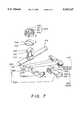
- FIG. 3shows a schematic view of the fastening process of a second preferred embodiment of the present invention.
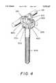
- FIG. 4shows a perspective view of the second preferred embodiment in combination according to the present invention.
- FIG. 5shows a schematic view of the fastening process of two sets of embodiments in combination according to the present invention.
- FIG. 6shows a perspective view of two sets of embodiments in combination according to the present invention.
- FIG. 7shows a schematic view of the fastening process of another two sets of embodiments in combination according to the present invention.
- FIG. 8shows a perspective view of another two sets of embodiments in combination according to the present invention.
- FIG. 9shows a sectional view of the rod body of the present invention.
- the present inventioncomprises a rod body 100 which is in fact a vertebral fixation rod, a close retaining bolt 200 having a retaining ring 210 and a bolt portion containing a rectangular head 220 which is provided with a retaining slot 221, a U-shaped connection element 300 having a U-shaped fitting portion 310 and a bone hook (connecting portion) 320, a fastening nut 400 provided with two bevel slide blocks, each of which has a bevel slide surface 411 and a platform 412, and a stop element 420.
- the present inventionfurther comprises a washer 500 having a fitting hole 530.
- the fitting portion 310is provided with a plurality of height adjusting knurls 311 for adjusting the height of the U-shaped connection element in the retaining mechanism of the vertebral fixation rod.
- the fastening nut 400has a fitting hole 430 for receiving therein the rectangular head 220 of the retaining bolt 200, which is rotated for a 90-degree angle before being located.
- FIG. 2shows the retaining mechanism of the vertebral fixation rod in combination according to the present invention.
- the reference numerals of FIG. 2are similar in definition to those of FIG. 1.
- FIG. 9A sectional view of the fastening nut 400 is shown in FIG. 9 in which the reference numerals of 411, 412, 420, 430 are similar in definition to the like reference numerals of FIG. 1.
- the bevel slide surface and the platform of another setare denoted respectively by the reference numerals of 411' and 412'.
- the stop elements 420are pushed radially to deform to an extent such that the stop elements 420 are able to elastically contact the sides of the rectangular head 220 when the fastening nut 400 is rotated for near 90-degree, and an inner and front corners 420a of the stop elements 420 are able to engage with the retaining slots 221 of the retaining bolt 200.
- FIG. 3shows another retaining mechanism of a vertebral fixation rod according to the present invention which is similar to FIG. 1.
- the reference numerals of FIG. 3are similar in definition to those of FIG. 1.
- the U-shaped connection element 300has a connecting portion 320 which is a bone screw while the U-shaped fitting portion 310 is provided on one side thereof with fine knurls 311.
- An angle adjusting washer 600has angle adjusting knurls 610, an arcuate surface 620 and a fitting hole 630.
- a height adjusting washer 700has angle adjusting knurls 710 and a fitting hole 730.
- the rod body 100is fitted into the retaining ring 210 of the retaining bolt 200.
- the angle adjusting washeris then fitted into the retaining ring 210 and is turned for an angle of about 90 degrees so as to cause the arcuate surface 620 to fit over the rod body 100.
- the height adjusting washer 700is fitted thereinto and is turned for an angle of about 90 degrees so as to cause the angle adjusting knurls 710 of the washer 700 and the angle adjusting knurls 610 of the washer 600 to form a specific angle.
- the U-shaped fitting portion 310 of the U-shaped connection element 300is fitted such that the angle adjusting knurls 311 and the angle adjusting knurls 720 of the height adjusting washer 700 are knurled.
- the fastening nut 400is fastened thereto and is then turned for an angle of about 90 degrees so as to cause the rectangular head 220 of the retaining bolt 200 to slide along the bevel slide surface 411 to the platform 412 where the retaining slot 221 is engaged securely with the stop element 420 of the fastening bolt 400.
- FIG. 4show a perspective view of the retaining mechanism of the vertebral fixation rod in FIG. 3 in combination.
- the reference numerals of FIG. 4are similar in definition to those of FIG. 3.
- FIG. 5The combination of two sets of retaining mechanisms of vertebral fixation rods is shown in FIG. 5 in which the reference numerals of 100, 200, 210, 220, 221, 300, 310, 320, 400, 410, 411, 420, 430, 500 and 530 are similar in definition to those of FIG. 1.
- the reference numerals of another set of the retaining mechanism of the vertebral fixation rodare 100', 200', 210', 221', 300', 310', 320', 400', 410', 411', 420', 430', 500', 530', which are similar in definition to the reference numerals of 100, 200, 210, 220, 221, 300, 310, 320, 400, 410, 411, 420, 430, 500 and 530.
- the U-shaped connection element 300 and the U-shaped connection element 300'are the same component member. However, the U-shaped fitting portion 310 of the U-shaped connection element 300 is the connecting portion 320' of the U-shaped connection element 300'.
- FIG. 6shows two sets of retaining mechanisms of vertebral fixation rods in FIG. 5 in combination.
- the reference numerals of FIG. 6are similar in definition to the like numerals of FIG. 5.
- the reference numerals of FIGS. 7 and 8are similar in definition to the like reference numerals of FIG. 1.
- the component parts of FIGS. 7 and 8are similar in construction to the like component parts of FIG. 1.
- the U-shaped connection element 300is of a combination type and is made up of fitting arms 301, 303, tubular bodies 302, 304, and the connecting portion 320, in which the tubular body 302(101') having male threads engageable with female threads provided in the inner wall of the tubular body 304(102').
- the tubular bodies 302 and 304are engaged with each other to form a rod body 100' for another set of the retaining mechanism of the vertebral fixation rod, and the connecting portion 320 here also serves as a retaining bolt 200' of this another set of the retaining mechanism of the vertebral fixation rod, which is made up of a retaining ring 210' and a bolt portion containing a rectangular head 220' which is provided with a retaining slot 221'.
Landscapes
- Health & Medical Sciences (AREA)
- Orthopedic Medicine & Surgery (AREA)
- Life Sciences & Earth Sciences (AREA)
- Neurology (AREA)
- Surgery (AREA)
- Heart & Thoracic Surgery (AREA)
- Engineering & Computer Science (AREA)
- Biomedical Technology (AREA)
- Nuclear Medicine, Radiotherapy & Molecular Imaging (AREA)
- Medical Informatics (AREA)
- Molecular Biology (AREA)
- Animal Behavior & Ethology (AREA)
- General Health & Medical Sciences (AREA)
- Public Health (AREA)
- Veterinary Medicine (AREA)
- Surgical Instruments (AREA)
- Prostheses (AREA)
Abstract
Description
The present invention relates generally to a vertebral fixation rod, and more particularly to a retaining mechanism of the vertebral fixation rod.
The conventional retaining mechanism of the vertebral fixation rod is generally composed of screws for fastening the vertebral fixation elements, such as bone screws, bone hooks, etc., with the vertebral fixation rod. The case in point is the U.S. Pat. No. 5,257,993 disclosing an invention in which the set screw 60 is used to fasten the rod 48 to a receiving slot of the vertebral fixation rod, which is formed by the U-shaped end opening 52 of the hook portion 22 and the transverse opening 90 of the end cap 24. A similar invention is disclosed in the U.S. Pat. No. 4,887,596 in which the fixation rod is fastened by means of adjustment screws 22 and 23. Such prior art methods of fastening an object with a fixation rod by means of the adjustment screws as described above are inherently defective in design in that the adjustment screws are vulnerable to becoming loosened by the vertebral movement, and that the effect of fastening the object with the fixation rod is seriously undermined.
It is therefore the primary objective of the present invention to provide a vertebral fixation rod having a fastening mechanism which can be fastened to the fixation rod quickly.
It is another objective of the present invention to provide a vertebral fixation rod with a retaining mechanism devoid of the adjustment screws of the prior art.
It is still another objective of the present invention to provide a vertebral fixation rod with a retaining mechanism comprising a distance adjusting washer and/or a direction adjusting washer.
In keeping with the principle of the present invention, the foregoing objectives of the present invention are attained by a retaining mechanism of the vertebral fixation rod, which comprises a rod body, a retaining bolt, a U-shaped connection element, and a fastening nut. The retaining bolt is provided at one end thereof with a retaining ring for holding the rod body and is further provided at another end thereof with a bolt portion having at the top end thereof a rectangular head. The U-shaped connection element is provided at one end thereof with a U-shaped fitting portion for holding the bolt portion of the retaining bolt and is further provided at another end thereof with a connecting portion for fastening a fractured vertebra or a vertebral fixation device. The fastening nut is engageable securely with the rectangular head of the bolt portion of the retaining bolt. The fastening nut is provided therein with a plurality of bevel slide blocks and with one or more stop elements. As the fastening nut is turned, the rectangular head of the retaining bolt is caused to move along the bevel slide blocks and stop at a predetermined position by engaging with the stop elements so as to fasten securely the fastening nut with the rectangular head of the retaining bolt.
The rod body of the present invention is similar in construction to any rod body of the prior art. In addition, any fixation element of the vertebral fixing and retrieving system, such as a bone screw, or the extension portion of a bone hook, may be used as the rod body of the present invention.
The retaining bolt of the present invention may be provided with a close retaining ring or an open retaining ring, depending on the surgical requirements.
The U-shaped connection element of the present invention is preferably provided at the U-shaped fitting portion thereof with a slot for enabling the U-shaped connection element to join with the rod body securely. In the meantime, another end of the U-shaped connection element may be similar in construction to any prior art connecting portion, such as a bone screw, or a bone hook, or a U-shaped fitting element, which is engageable with a vertebral fixation device.
The fastening nut of the present invention is preferably provided with a platform located in the sliding direction of the bevel slide blocks of the fastening nut so as to cause the rectangular head of the retaining bolt of the present invention to be retained on the platform at such time when the retaining bolt is located after being caused to slide along the bevel slide blocks. As a result, the connection area between the retaining bolt and the fastening nut is increased effectively. Such a connection area as described above may be further increased by adding additional bevel slide blocks in the fastening nut. However, the bevel slide blocks so added must be able to cooperate with the rectangular head of the retaining bolt.
The fastening nut of the present invention described above is provided at an appropriate position thereof with one or more stop elements for fastening the retaining bolt which is located. The appropriate position referred to above is the position at which the fastening nut is engageable with the retaining bolt. For example, the appropriate position may be a side or bottom of the rectangular head of the retaining bolt. The stop element which is provided at a circular fastening nut may be a fastening piece or a fastening tenon. If the retaining bolt is provided at the bottom of the rectangular head thereof with a retaining recessed slot or retaining projected slot, the stop element is either a retaining projected slot or a retaining recessed slot, which is engageable with the retaining recessed slot or the retaining projected slot of the rectangular head of the retaining bolt.
The bevel slide blocks of the fastening nut are arranged on two opposite sides of the inner surface of the circular fastening nut such that the interior of the fastening nut is provided with a rectangular space dimensioned to allow the rectangular head of the retaining bolt to pass therethrough. It is suggested that the fastening nut of the present invention is preferably provided with two bevel slide blocks in such a manner that each of these two bevel slide blocks has a bevel slide surface and a platform, and the line connecting the two edges between the platforms and the bevel slide surfaces intersects the central axis of the circular nut of the fastening nut (FIG. 9).
The rectangular space of the fastening nut and the rectangular head of the retaining bolt of the present invention have no specific shape and size; nevertheless they must be able to cooperate with each other. Suppose that R denotes the inner diameter of the fastening nut; 2R, the diameter of the fastening nut; L, the distance between the inner sides of the two bevel slide blocks of the rectangular space of the fastening nut; I1, the length of the long side of the rectangular head of the retaining bolt; and I2, the length of the short side of the rectangular head of the retaining bolt. It is then expected that the diameter (2R) of the fastening nut is greater than the length of the long side of the rectangular head of the retaining bolt, I1, and that the magnitude of the distance between the inner sides of the two bevel slide blocks, L, is between the length of the long side of the rectangular head of the retaining bolt, 11, and the length of the short side of the rectangular head of the retaining bolt, I2.
In order to reinforce the fastening effect of the vertebral fixation rod of the present invention, it is suggested that a washer may be disposed between the U-shaped connection element and the fastening nut. If necessary, an angle-adjusting washer such as the washer 25 disclosed in the U.S. Pat. No. 5,261,909 or a distance-adjusting connection element such as the offset connector 40 disclosed also in the above-mentioned U.S. Patent may be used in conjunction with the present invention.
The foregoing objectives, features and advantages of the present invention will be more readily understood upon a thoughtful deliberation of the following detailed description of the preferred embodiments of the present invention in conjunction with the accompanying drawings.
FIG. 1 shows a schematic view of the fastening process of a first preferred embodiment of the present invention.
FIG. 2 shows a perspective view of the first preferred embodiment in combination according to the present invention.
FIG. 3 shows a schematic view of the fastening process of a second preferred embodiment of the present invention.
FIG. 4 shows a perspective view of the second preferred embodiment in combination according to the present invention.
FIG. 5 shows a schematic view of the fastening process of two sets of embodiments in combination according to the present invention.
FIG. 6 shows a perspective view of two sets of embodiments in combination according to the present invention.
FIG. 7 shows a schematic view of the fastening process of another two sets of embodiments in combination according to the present invention.
FIG. 8 shows a perspective view of another two sets of embodiments in combination according to the present invention.
FIG. 9 shows a sectional view of the rod body of the present invention.
As shown in FIG. 1, the present invention comprises arod body 100 which is in fact a vertebral fixation rod, a closeretaining bolt 200 having aretaining ring 210 and a bolt portion containing arectangular head 220 which is provided with aretaining slot 221, aU-shaped connection element 300 having aU-shaped fitting portion 310 and a bone hook (connecting portion) 320, afastening nut 400 provided with two bevel slide blocks, each of which has abevel slide surface 411 and aplatform 412, and astop element 420. The present invention further comprises awasher 500 having afitting hole 530. Thefitting portion 310 is provided with a plurality ofheight adjusting knurls 311 for adjusting the height of the U-shaped connection element in the retaining mechanism of the vertebral fixation rod. Thefastening nut 400 has afitting hole 430 for receiving therein therectangular head 220 of theretaining bolt 200, which is rotated for a 90-degree angle before being located.
FIG. 2 shows the retaining mechanism of the vertebral fixation rod in combination according to the present invention. The reference numerals of FIG. 2 are similar in definition to those of FIG. 1.
A sectional view of thefastening nut 400 is shown in FIG. 9 in which the reference numerals of 411, 412, 420, 430 are similar in definition to the like reference numerals of FIG. 1. The bevel slide surface and the platform of another set are denoted respectively by the reference numerals of 411' and 412'. Thestop elements 420 are pushed radially to deform to an extent such that thestop elements 420 are able to elastically contact the sides of therectangular head 220 when thefastening nut 400 is rotated for near 90-degree, and an inner andfront corners 420a of thestop elements 420 are able to engage with theretaining slots 221 of theretaining bolt 200.
FIG. 3 shows another retaining mechanism of a vertebral fixation rod according to the present invention which is similar to FIG. 1. The reference numerals of FIG. 3 are similar in definition to those of FIG. 1. The U-shapedconnection element 300 has a connectingportion 320 which is a bone screw while the U-shapedfitting portion 310 is provided on one side thereof withfine knurls 311. Anangle adjusting washer 600 hasangle adjusting knurls 610, anarcuate surface 620 and afitting hole 630. Aheight adjusting washer 700 has angle adjusting knurls 710 and afitting hole 730. In combination, therod body 100 is fitted into the retainingring 210 of the retainingbolt 200. The angle adjusting washer is then fitted into the retainingring 210 and is turned for an angle of about 90 degrees so as to cause thearcuate surface 620 to fit over therod body 100. Thereafter, theheight adjusting washer 700 is fitted thereinto and is turned for an angle of about 90 degrees so as to cause the angle adjusting knurls 710 of thewasher 700 and theangle adjusting knurls 610 of thewasher 600 to form a specific angle. The U-shapedfitting portion 310 of theU-shaped connection element 300 is fitted such that theangle adjusting knurls 311 and theangle adjusting knurls 720 of theheight adjusting washer 700 are knurled. Thefastening nut 400 is fastened thereto and is then turned for an angle of about 90 degrees so as to cause therectangular head 220 of the retainingbolt 200 to slide along thebevel slide surface 411 to theplatform 412 where the retainingslot 221 is engaged securely with thestop element 420 of thefastening bolt 400.
FIG. 4 show a perspective view of the retaining mechanism of the vertebral fixation rod in FIG. 3 in combination. The reference numerals of FIG. 4 are similar in definition to those of FIG. 3.
The combination of two sets of retaining mechanisms of vertebral fixation rods is shown in FIG. 5 in which the reference numerals of 100, 200, 210, 220, 221, 300, 310, 320, 400, 410, 411, 420, 430, 500 and 530 are similar in definition to those of FIG. 1. The reference numerals of another set of the retaining mechanism of the vertebral fixation rod are 100', 200', 210', 221', 300', 310', 320', 400', 410', 411', 420', 430', 500', 530', which are similar in definition to the reference numerals of 100, 200, 210, 220, 221, 300, 310, 320, 400, 410, 411, 420, 430, 500 and 530. TheU-shaped connection element 300 and the U-shaped connection element 300' are the same component member. However, the U-shapedfitting portion 310 of theU-shaped connection element 300 is the connecting portion 320' of the U-shaped connection element 300'. Similarly, the connectingportion 320 of theU-shaped connection element 300 is the U-shaped fitting portion 310' of the U-shaped connection element 300'. The retainingbolts 200 and 200' are of an open type. The fastening process is similar in sequence to that shown in FIG. 1. FIG. 6 shows two sets of retaining mechanisms of vertebral fixation rods in FIG. 5 in combination. The reference numerals of FIG. 6 are similar in definition to the like numerals of FIG. 5.
The reference numerals of FIGS. 7 and 8 are similar in definition to the like reference numerals of FIG. 1. The component parts of FIGS. 7 and 8 are similar in construction to the like component parts of FIG. 1. TheU-shaped connection element 300 is of a combination type and is made up offitting arms tubular bodies portion 320, in which the tubular body 302(101') having male threads engageable with female threads provided in the inner wall of the tubular body 304(102'). Thetubular bodies portion 320 here also serves as a retaining bolt 200' of this another set of the retaining mechanism of the vertebral fixation rod, which is made up of a retainingring 210' and a bolt portion containing a rectangular head 220' which is provided with a retaining slot 221'.
Claims (15)
1. A retaining mechanism of a vertebral fixation rod comprising:
a retaining bolt provided at one end thereof with a retaining ring for holding a rod body, said retaining bolt further provided at another end thereof with a bolt portion having a rectangular head;
a U-shaped connection element provided at one end thereof with a U-shaped fitting portion dimensioned to fit over said bolt portion of said retaining bolt, said U-shaped connection element further provided at another end thereof with a connecting portion engageable with a vertebra to be fixed or with a vertebral fixation device; and
a fastening nut engageable with said rectangular head of said bolt portion of said retaining bolt, said fastening nut provided therein with a plurality of bevel slide blocks for enabling said retaining bolt to slide along said bevel slide blocks when said fastening nut is rotated, and said fastening nut further provided with at least one stop element adapted to stop said fastening nut when it is rotated to a predetermined degree by engaging the at least one stop element with the rectangular head of the retaining bolt.
2. The retaining mechanism of a vertebral fixation rod as defined in claim 1 further comprising, in combination a rod body, wherein said rod body is a fixation rod.
3. The retaining mechanism of a vertebral fixation rod as defined in claim 1 further comprising, in combination a rod body, wherein said rod body is a connection rod body.
4. The retaining mechanism of a vertebral fixation rod as defined in claim 1, wherein said fastening nut has an inner diameter greater than the length of a long side of said rectangular head of said retaining bolt; and wherein said fastening nut further has a rectangular space having a short side distance intermediary between the length of said long side of said rectangular head and the length of said short side of said rectangular head.
5. The retaining mechanism of a vertebral fixation rod as defined in claim 4 further comprising an angle adjusting washer adapted to fit about the bolt portion of said retaining bolt.
6. The retaining mechanism of a vertebral fixation rod as defined in claim 4, further comprising a height adjusting washer adapted to fit about the bolt portion of said retaining bolt.
7. The retaining mechanism of a vertebral fixation rod as defined in claim 4, further comprising a distance adjusting connection element adapted to fit about the bolt portion of said retaining bolt.
8. The retaining mechanism of a vertebral fixation rod as defined in claim 4, further comprising an offset connector adapted to fit about the bolt portion of said retaining bolt.
9. The retaining mechanism of a vertebral fixation rod as defined in claim 1 further comprising an angle adjusting washer adapted to fit about the bolt portion of said retaining bolt.
10. The retaining mechanism of a vertebral fixation rod as defined in claim 1, wherein said plurality of bevel slide blocks of the fastening nut comprise two bevel slide blocks arranged on two opposite sides of an inner surface of the fastening nut such that an interior of the fastening nut is provided with a rectangular space dimensioned to allow the rectangular head of the retaining bolt to pass therethrough.
11. The retaining mechanism of a vertebral fixation rod as defined in claim 10, wherein the two bevel slide blocks has a bevel slide surface and a platform, and a line connecting two edges between the platforms and the bevel slide surfaces intersects a central axis of the fastening nut.
12. The retaining mechanism of a vertebral fixation rod as defined in claim 1, further comprising a height adjusting washer adapted to fit about the bolt portion of said retaining bolt.
13. The retaining mechanism of a vertebral fixation rod as defined in claim 1, further comprising a distance adjusting connection element adapted to fit about the bolt portion of said retaining bolt.
14. The retaining mechanism of a vertebral fixation rod as defined in claim 1, further comprising an offset connector adapted to fit about the bolt portion of said retaining bolt.
15. The retaining mechanism of a vertebral fixation rod as defined in claim 1, wherein said fastening nut is of a circular construction.
Priority Applications (1)
| Application Number | Priority Date | Filing Date | Title |
|---|---|---|---|
| US08/419,698US5545167A (en) | 1995-04-11 | 1995-04-11 | Retaining mechanism of vertebral fixation rod |
Applications Claiming Priority (1)
| Application Number | Priority Date | Filing Date | Title |
|---|---|---|---|
| US08/419,698US5545167A (en) | 1995-04-11 | 1995-04-11 | Retaining mechanism of vertebral fixation rod |
Publications (1)
| Publication Number | Publication Date |
|---|---|
| US5545167Atrue US5545167A (en) | 1996-08-13 |
Family
ID=23663370
Family Applications (1)
| Application Number | Title | Priority Date | Filing Date |
|---|---|---|---|
| US08/419,698Expired - Fee RelatedUS5545167A (en) | 1995-04-11 | 1995-04-11 | Retaining mechanism of vertebral fixation rod |
Country Status (1)
| Country | Link |
|---|---|
| US (1) | US5545167A (en) |
Cited By (68)
| Publication number | Priority date | Publication date | Assignee | Title |
|---|---|---|---|---|
| US5876403A (en)* | 1996-09-06 | 1999-03-02 | Robert Reid Inc. | Bone-fixing devices |
| US5921985A (en)* | 1998-02-10 | 1999-07-13 | Texas Scottish Rite Hospital | External fixation device and method |
| US6551318B1 (en) | 2000-07-26 | 2003-04-22 | Stahurski Consulting Inc. | Spinal column retaining apparatus |
| US6610063B2 (en) | 2000-07-28 | 2003-08-26 | Synthes (Usa) | Spinal fixation system |
| US20030176862A1 (en)* | 2000-10-23 | 2003-09-18 | Taylor Harold Sparr | Taper-locked adjustable connector |
| US6656180B2 (en) | 2001-09-05 | 2003-12-02 | Stahurski Consulting Inc. | Apparatus for retaining vertebrae in a desired spatial relationship |
| US6682532B2 (en) | 2002-03-22 | 2004-01-27 | Depuy Acromed, Inc. | Coupling system and method for extending spinal instrumentation |
| EP1397999A1 (en)* | 2002-09-12 | 2004-03-17 | Showa IKA Kohgyo Co., Ltd. | Rod connector |
| US6709434B1 (en)* | 1998-07-30 | 2004-03-23 | Sofamor S.N.C. | Spinal osteosynthesis device |
| US20040133203A1 (en)* | 2002-10-28 | 2004-07-08 | Young J Stewart | Multi-axial, cross-link connector system for spinal implants |
| US20040172020A1 (en)* | 2001-04-06 | 2004-09-02 | Jacques Beaurain | Spinal osteosynthesis device and preparation method |
| US20050090821A1 (en)* | 2003-10-22 | 2005-04-28 | Gregory Berrevoets | Crosslink for securing spinal rods |
| US20050107788A1 (en)* | 2001-12-12 | 2005-05-19 | Jacques Beaurain | Implant for osseous anchoring with polyaxial head |
| US20060195096A1 (en)* | 2005-02-09 | 2006-08-31 | David Lee | Bone fixation apparatus |
| US20060247636A1 (en)* | 1998-06-17 | 2006-11-02 | Hansen Yuan | Methods for securing spinal rods |
| US7141051B2 (en) | 2003-02-05 | 2006-11-28 | Pioneer Laboratories, Inc. | Low profile spinal fixation system |
| US20070072459A1 (en)* | 2005-09-23 | 2007-03-29 | Stahurski Consulting Inc. | Apparatus for retaining vertebrae |
| US20070282355A1 (en)* | 2006-06-01 | 2007-12-06 | Wilson-Cook Medical Inc. | Release mechanisms for a clip device |
| US20080045955A1 (en)* | 2006-08-16 | 2008-02-21 | Berrevoets Gregory A | Spinal Rod Anchor Device and Method |
| US7344537B1 (en) | 2004-03-05 | 2008-03-18 | Theken Spine, Llc | Bone fixation rod system |
| US20080177323A1 (en)* | 2006-10-18 | 2008-07-24 | Null William B | Orthopedic revision connector |
| US20080234745A1 (en)* | 2007-03-06 | 2008-09-25 | Warsaw Orthopedic, Inc. | Self-Aligning Attachment Devices and Methods for Attaching an Elongated Member to a Vertebral Member |
| US20090005817A1 (en)* | 2007-04-30 | 2009-01-01 | Adam Friedrich | Flexible Spine Stabilization System |
| US7628799B2 (en) | 2005-08-23 | 2009-12-08 | Aesculap Ag & Co. Kg | Rod to rod connector |
| US7635380B2 (en) | 2007-06-05 | 2009-12-22 | Spartek Medical, Inc. | Bone anchor with a compressor element for receiving a rod for a dynamic stabilization and motion preservation spinal implantation system and method |
| US7744632B2 (en) | 2006-12-20 | 2010-06-29 | Aesculap Implant Systems, Inc. | Rod to rod connector |
| US20100218346A1 (en)* | 2009-03-02 | 2010-09-02 | Daniels James L | Removable pull fascia |
| US20100274286A1 (en)* | 2009-04-23 | 2010-10-28 | Spinal Elements, Inc. | Transverse connectors |
| US20110027048A1 (en)* | 2009-05-11 | 2011-02-03 | Shue Larry N | Threadless Nut |
| US20110106164A1 (en)* | 2009-10-30 | 2011-05-05 | Warsaw Othropedic, Inc. | Apparatus for implementing a spinal fixation system with supplemental fixation |
| US7963978B2 (en) | 2007-06-05 | 2011-06-21 | Spartek Medical, Inc. | Method for implanting a deflection rod system and customizing the deflection rod system for a particular patient need for dynamic stabilization and motion preservation spinal implantation system |
| US20110184416A1 (en)* | 2010-01-28 | 2011-07-28 | Warsaw Orthopedic, Inc. | Pre-assembled construct for insertion into a patient |
| US7993372B2 (en) | 2007-06-05 | 2011-08-09 | Spartek Medical, Inc. | Dynamic stabilization and motion preservation spinal implantation system with a shielded deflection rod system and method |
| US8007518B2 (en) | 2008-02-26 | 2011-08-30 | Spartek Medical, Inc. | Load-sharing component having a deflectable post and method for dynamic stabilization of the spine |
| US8012181B2 (en) | 2008-02-26 | 2011-09-06 | Spartek Medical, Inc. | Modular in-line deflection rod and bone anchor system and method for dynamic stabilization of the spine |
| US8016861B2 (en) | 2008-02-26 | 2011-09-13 | Spartek Medical, Inc. | Versatile polyaxial connector assembly and method for dynamic stabilization of the spine |
| US8021396B2 (en) | 2007-06-05 | 2011-09-20 | Spartek Medical, Inc. | Configurable dynamic spinal rod and method for dynamic stabilization of the spine |
| US8043337B2 (en) | 2006-06-14 | 2011-10-25 | Spartek Medical, Inc. | Implant system and method to treat degenerative disorders of the spine |
| US8048115B2 (en) | 2007-06-05 | 2011-11-01 | Spartek Medical, Inc. | Surgical tool and method for implantation of a dynamic bone anchor |
| US8057517B2 (en) | 2008-02-26 | 2011-11-15 | Spartek Medical, Inc. | Load-sharing component having a deflectable post and centering spring and method for dynamic stabilization of the spine |
| US8083775B2 (en) | 2008-02-26 | 2011-12-27 | Spartek Medical, Inc. | Load-sharing bone anchor having a natural center of rotation and method for dynamic stabilization of the spine |
| US8083772B2 (en) | 2007-06-05 | 2011-12-27 | Spartek Medical, Inc. | Dynamic spinal rod assembly and method for dynamic stabilization of the spine |
| US8092501B2 (en) | 2007-06-05 | 2012-01-10 | Spartek Medical, Inc. | Dynamic spinal rod and method for dynamic stabilization of the spine |
| US8097024B2 (en) | 2008-02-26 | 2012-01-17 | Spartek Medical, Inc. | Load-sharing bone anchor having a deflectable post and method for stabilization of the spine |
| US8114134B2 (en) | 2007-06-05 | 2012-02-14 | Spartek Medical, Inc. | Spinal prosthesis having a three bar linkage for motion preservation and dynamic stabilization of the spine |
| WO2012031000A1 (en)* | 2010-09-03 | 2012-03-08 | International Spinal Innovations, Llc | Polyaxial vertebral anchor assembly with vertical adjustment and split lock |
| US8162988B2 (en)* | 2001-10-18 | 2012-04-24 | Ldr Medical | Plate for osteosynthesis device and method of preassembling such device |
| US8211155B2 (en) | 2008-02-26 | 2012-07-03 | Spartek Medical, Inc. | Load-sharing bone anchor having a durable compliant member and method for dynamic stabilization of the spine |
| US8221457B2 (en) | 2001-10-18 | 2012-07-17 | Ldr Medical | Progressive approach osteosynthesis device and preassembly method |
| US8257397B2 (en) | 2009-12-02 | 2012-09-04 | Spartek Medical, Inc. | Low profile spinal prosthesis incorporating a bone anchor having a deflectable post and a compound spinal rod |
| US8267979B2 (en) | 2008-02-26 | 2012-09-18 | Spartek Medical, Inc. | Load-sharing bone anchor having a deflectable post and axial spring and method for dynamic stabilization of the spine |
| US8333792B2 (en) | 2008-02-26 | 2012-12-18 | Spartek Medical, Inc. | Load-sharing bone anchor having a deflectable post and method for dynamic stabilization of the spine |
| US8337536B2 (en) | 2008-02-26 | 2012-12-25 | Spartek Medical, Inc. | Load-sharing bone anchor having a deflectable post with a compliant ring and method for stabilization of the spine |
| US8343219B2 (en) | 2007-06-08 | 2013-01-01 | Ldr Medical | Intersomatic cage, intervertebral prosthesis, anchoring device and implantation instruments |
| US8430916B1 (en) | 2012-02-07 | 2013-04-30 | Spartek Medical, Inc. | Spinal rod connectors, methods of use, and spinal prosthesis incorporating spinal rod connectors |
| US8518085B2 (en) | 2010-06-10 | 2013-08-27 | Spartek Medical, Inc. | Adaptive spinal rod and methods for stabilization of the spine |
| US20130318775A1 (en)* | 2012-05-30 | 2013-12-05 | Christopher Peters | System And Method For Mounting A Handheld Electronic Device |
| US20140052189A1 (en)* | 2012-08-15 | 2014-02-20 | Blackstone Medical, Inc. | Pivoting spinal fixation devices |
| US8771319B2 (en) | 2012-04-16 | 2014-07-08 | Aesculap Implant Systems, Llc | Rod to rod cross connector |
| EP2498696A4 (en)* | 2009-11-09 | 2014-09-03 | Applied Orthopaedics Llp | Apparatus for retaining bone |
| US8828056B2 (en) | 2012-04-16 | 2014-09-09 | Aesculap Implant Systems, Llc | Rod to rod cross connector |
| US8845691B2 (en) | 2003-09-01 | 2014-09-30 | Ldr Medical | Osseous anchoring implant with a polyaxial head and method for installing the implant |
| US9179940B2 (en) | 2005-12-06 | 2015-11-10 | Globus Medical, Inc. | System and method for replacement of spinal motion segment |
| US10130373B2 (en) | 2011-09-15 | 2018-11-20 | Teleflex Medical Incorporated | Automatic surgical ligation clip applier |
| US10307166B2 (en) | 2011-09-15 | 2019-06-04 | Teleflex Medical Incorporated | Manual surgical ligation clip applier |
| US10485596B2 (en) | 2016-12-06 | 2019-11-26 | Medos International Sàrl | Longitudinally-adjustable bone anchors and related methods |
| US10575876B2 (en) | 2016-04-20 | 2020-03-03 | K2M, Inc. | Spinal stabilization assemblies with bone hooks |
| US20210290272A1 (en)* | 2015-12-23 | 2021-09-23 | Xiangyang Ma | Customized posterior atlantoaxial reduction fixatorwith screws and rods |
Citations (7)
| Publication number | Priority date | Publication date | Assignee | Title |
|---|---|---|---|---|
| US4657462A (en)* | 1985-08-08 | 1987-04-14 | Simmons Fastener Corporation | Quarter-turn fastener |
| US5209752A (en)* | 1991-12-04 | 1993-05-11 | Danek Medical, Inc. | Lateral offset connector for spinal implant system |
| US5246442A (en)* | 1991-12-31 | 1993-09-21 | Danek Medical, Inc. | Spinal hook |
| US5257993A (en)* | 1991-10-04 | 1993-11-02 | Acromed Corporation | Top-entry rod retainer |
| US5261909A (en)* | 1992-02-18 | 1993-11-16 | Danek Medical, Inc. | Variable angle screw for spinal implant system |
| US5282801A (en)* | 1993-02-17 | 1994-02-01 | Danek Medical, Inc. | Top tightening clamp assembly for a spinal fixation system |
| US5368427A (en)* | 1993-02-08 | 1994-11-29 | General Motors Corporation | Quarter turn fastener |
- 1995
- 1995-04-11USUS08/419,698patent/US5545167A/ennot_activeExpired - Fee Related
Patent Citations (7)
| Publication number | Priority date | Publication date | Assignee | Title |
|---|---|---|---|---|
| US4657462A (en)* | 1985-08-08 | 1987-04-14 | Simmons Fastener Corporation | Quarter-turn fastener |
| US5257993A (en)* | 1991-10-04 | 1993-11-02 | Acromed Corporation | Top-entry rod retainer |
| US5209752A (en)* | 1991-12-04 | 1993-05-11 | Danek Medical, Inc. | Lateral offset connector for spinal implant system |
| US5246442A (en)* | 1991-12-31 | 1993-09-21 | Danek Medical, Inc. | Spinal hook |
| US5261909A (en)* | 1992-02-18 | 1993-11-16 | Danek Medical, Inc. | Variable angle screw for spinal implant system |
| US5368427A (en)* | 1993-02-08 | 1994-11-29 | General Motors Corporation | Quarter turn fastener |
| US5282801A (en)* | 1993-02-17 | 1994-02-01 | Danek Medical, Inc. | Top tightening clamp assembly for a spinal fixation system |
Cited By (159)
| Publication number | Priority date | Publication date | Assignee | Title |
|---|---|---|---|---|
| US5876403A (en)* | 1996-09-06 | 1999-03-02 | Robert Reid Inc. | Bone-fixing devices |
| US5921985A (en)* | 1998-02-10 | 1999-07-13 | Texas Scottish Rite Hospital | External fixation device and method |
| US8313510B2 (en) | 1998-06-17 | 2012-11-20 | Howmedica Osteonics Corp. | Device for securing spinal rods |
| US20090318974A1 (en)* | 1998-06-17 | 2009-12-24 | Stryker Spine | Device For Securing Spinal Rods |
| US20100268280A1 (en)* | 1998-06-17 | 2010-10-21 | Howmedica Osteonics Corp. | Device for securing spinal rods |
| US7909856B2 (en) | 1998-06-17 | 2011-03-22 | Howmedica Osteonics Corp. | Methods for securing spinal rods |
| US8808327B2 (en) | 1998-06-17 | 2014-08-19 | Howmedica Osteonics Corp. | Device for securing spinal rods |
| US8038702B2 (en)* | 1998-06-17 | 2011-10-18 | Howmedica Osteonics Corp. | Device for securing spinal rods |
| US20060247636A1 (en)* | 1998-06-17 | 2006-11-02 | Hansen Yuan | Methods for securing spinal rods |
| US6709434B1 (en)* | 1998-07-30 | 2004-03-23 | Sofamor S.N.C. | Spinal osteosynthesis device |
| US6551318B1 (en) | 2000-07-26 | 2003-04-22 | Stahurski Consulting Inc. | Spinal column retaining apparatus |
| US8221470B2 (en)* | 2000-07-28 | 2012-07-17 | Synthes Usa, Llc | Spinal fixation system |
| US20070055243A1 (en)* | 2000-07-28 | 2007-03-08 | Synthes (Usa) | Spinal fixation system |
| US9504499B2 (en) | 2000-07-28 | 2016-11-29 | DePuy Synthes Products, Inc. | Spinal fixation system |
| US20100042166A1 (en)* | 2000-07-28 | 2010-02-18 | Kumar Kris G | Spinal fixation system |
| US6610063B2 (en) | 2000-07-28 | 2003-08-26 | Synthes (Usa) | Spinal fixation system |
| US7118571B2 (en) | 2000-07-28 | 2006-10-10 | Synthes (U.S.A.) | Spinal fixation system |
| US8551146B2 (en) | 2000-07-28 | 2013-10-08 | DePuy Synthes Products, LLC | Spinal fixation system |
| US20040039386A1 (en)* | 2000-07-28 | 2004-02-26 | Synthes (Usa) | Spinal fixation system |
| US7927353B2 (en)* | 2000-10-23 | 2011-04-19 | Warsaw Orthopedic, Inc. | Taper-locked adjustable connector |
| US20030176862A1 (en)* | 2000-10-23 | 2003-09-18 | Taylor Harold Sparr | Taper-locked adjustable connector |
| US20040172020A1 (en)* | 2001-04-06 | 2004-09-02 | Jacques Beaurain | Spinal osteosynthesis device and preparation method |
| US7507248B2 (en) | 2001-04-06 | 2009-03-24 | Ldr Medical | Spinal osteosynthesis device and preparation method |
| US6656180B2 (en) | 2001-09-05 | 2003-12-02 | Stahurski Consulting Inc. | Apparatus for retaining vertebrae in a desired spatial relationship |
| US8162988B2 (en)* | 2001-10-18 | 2012-04-24 | Ldr Medical | Plate for osteosynthesis device and method of preassembling such device |
| US8221457B2 (en) | 2001-10-18 | 2012-07-17 | Ldr Medical | Progressive approach osteosynthesis device and preassembly method |
| US9326795B2 (en) | 2001-12-12 | 2016-05-03 | Ldr Medical | Implant for osseous anchoring with polyaxial head |
| US20050107788A1 (en)* | 2001-12-12 | 2005-05-19 | Jacques Beaurain | Implant for osseous anchoring with polyaxial head |
| US6682532B2 (en) | 2002-03-22 | 2004-01-27 | Depuy Acromed, Inc. | Coupling system and method for extending spinal instrumentation |
| US7572278B2 (en) | 2002-09-12 | 2009-08-11 | Showa Ika Kohgyo Co., Ltd. | Rod connector |
| US20060129150A1 (en)* | 2002-09-12 | 2006-06-15 | Showa Ika Kohgyo Co., Ltd. | Rod connector |
| US7569070B2 (en) | 2002-09-12 | 2009-08-04 | Showa Ika Kohgyo Co., Ltd. | Rod connector |
| EP1397999A1 (en)* | 2002-09-12 | 2004-03-17 | Showa IKA Kohgyo Co., Ltd. | Rod connector |
| US8029543B2 (en)* | 2002-10-28 | 2011-10-04 | Warsaw Othopedic, Inc. | Multi-axial, cross-link connector system for spinal implants |
| US20040133203A1 (en)* | 2002-10-28 | 2004-07-08 | Young J Stewart | Multi-axial, cross-link connector system for spinal implants |
| US7141051B2 (en) | 2003-02-05 | 2006-11-28 | Pioneer Laboratories, Inc. | Low profile spinal fixation system |
| US8075590B2 (en) | 2003-02-05 | 2011-12-13 | Pioneer Surgical Technology, Inc. | Low profile spinal fixation system |
| US20070055235A1 (en)* | 2003-02-05 | 2007-03-08 | Pioneer Laboratories, Inc. | Low profile spinal fixation system |
| US8845691B2 (en) | 2003-09-01 | 2014-09-30 | Ldr Medical | Osseous anchoring implant with a polyaxial head and method for installing the implant |
| US20050090821A1 (en)* | 2003-10-22 | 2005-04-28 | Gregory Berrevoets | Crosslink for securing spinal rods |
| US7744633B2 (en)* | 2003-10-22 | 2010-06-29 | Pioneer Surgical Technology, Inc. | Crosslink for securing spinal rods |
| US7927355B2 (en) | 2003-10-22 | 2011-04-19 | Pioneer Surgical Technology, Inc. | Crosslink for securing spinal rods |
| US20060271051A1 (en)* | 2003-10-22 | 2006-11-30 | Pioneer Laboratories, Inc. | Crossllink for securing spinal rods |
| US7344537B1 (en) | 2004-03-05 | 2008-03-18 | Theken Spine, Llc | Bone fixation rod system |
| US20060195096A1 (en)* | 2005-02-09 | 2006-08-31 | David Lee | Bone fixation apparatus |
| US7896905B2 (en)* | 2005-02-09 | 2011-03-01 | David Lee | Bone fixation apparatus |
| US7628799B2 (en) | 2005-08-23 | 2009-12-08 | Aesculap Ag & Co. Kg | Rod to rod connector |
| US20070072459A1 (en)* | 2005-09-23 | 2007-03-29 | Stahurski Consulting Inc. | Apparatus for retaining vertebrae |
| US8075597B2 (en) | 2005-09-23 | 2011-12-13 | Applied Orthopaedics Llc | Apparatus for retaining vertebrae |
| US9179940B2 (en) | 2005-12-06 | 2015-11-10 | Globus Medical, Inc. | System and method for replacement of spinal motion segment |
| US20070282355A1 (en)* | 2006-06-01 | 2007-12-06 | Wilson-Cook Medical Inc. | Release mechanisms for a clip device |
| US8172882B2 (en) | 2006-06-14 | 2012-05-08 | Spartek Medical, Inc. | Implant system and method to treat degenerative disorders of the spine |
| US8043337B2 (en) | 2006-06-14 | 2011-10-25 | Spartek Medical, Inc. | Implant system and method to treat degenerative disorders of the spine |
| US8062340B2 (en) | 2006-08-16 | 2011-11-22 | Pioneer Surgical Technology, Inc. | Spinal rod anchor device and method |
| US20080045955A1 (en)* | 2006-08-16 | 2008-02-21 | Berrevoets Gregory A | Spinal Rod Anchor Device and Method |
| US8298269B2 (en) | 2006-10-18 | 2012-10-30 | Warsaw Orthopedic, Inc. | Orthopedic revision connector |
| US20080177323A1 (en)* | 2006-10-18 | 2008-07-24 | Null William B | Orthopedic revision connector |
| US7976567B2 (en) | 2006-10-18 | 2011-07-12 | Warsaw Orthopedic, Inc. | Orthopedic revision connector |
| US7744632B2 (en) | 2006-12-20 | 2010-06-29 | Aesculap Implant Systems, Inc. | Rod to rod connector |
| US7959655B2 (en) | 2007-03-06 | 2011-06-14 | Warsaw Orthopedic, Inc. | Self-aligning attachment devices and methods for attaching an elongated member to a vertebral member |
| US20080234745A1 (en)* | 2007-03-06 | 2008-09-25 | Warsaw Orthopedic, Inc. | Self-Aligning Attachment Devices and Methods for Attaching an Elongated Member to a Vertebral Member |
| US9220538B2 (en) | 2007-04-30 | 2015-12-29 | Globus Medical, Inc. | Flexible element for spine stabilization system |
| US20090005817A1 (en)* | 2007-04-30 | 2009-01-01 | Adam Friedrich | Flexible Spine Stabilization System |
| US9339297B2 (en) | 2007-04-30 | 2016-05-17 | Globus Medical, Inc. | Flexible spine stabilization system |
| US9211142B2 (en) | 2007-04-30 | 2015-12-15 | Globus Medical, Inc. | Flexible element for spine stabilization system |
| US8465526B2 (en) | 2007-04-30 | 2013-06-18 | Globus Medical, Inc. | Flexible spine stabilization system |
| US8317836B2 (en) | 2007-06-05 | 2012-11-27 | Spartek Medical, Inc. | Bone anchor for receiving a rod for stabilization and motion preservation spinal implantation system and method |
| US8105356B2 (en) | 2007-06-05 | 2012-01-31 | Spartek Medical, Inc. | Bone anchor with a curved mounting element for a dynamic stabilization and motion preservation spinal implantation system and method |
| US8048128B2 (en) | 2007-06-05 | 2011-11-01 | Spartek Medical, Inc. | Revision system and method for a dynamic stabilization and motion preservation spinal implantation system and method |
| US8048123B2 (en) | 2007-06-05 | 2011-11-01 | Spartek Medical, Inc. | Spine implant with a deflection rod system and connecting linkages and method |
| US8048122B2 (en) | 2007-06-05 | 2011-11-01 | Spartek Medical, Inc. | Spine implant with a dual deflection rod system including a deflection limiting sheild associated with a bone screw and method |
| US8052722B2 (en) | 2007-06-05 | 2011-11-08 | Spartek Medical, Inc. | Dual deflection rod system for a dynamic stabilization and motion preservation spinal implantation system and method |
| US8052721B2 (en) | 2007-06-05 | 2011-11-08 | Spartek Medical, Inc. | Multi-dimensional horizontal rod for a dynamic stabilization and motion preservation spinal implantation system and method |
| US8057514B2 (en) | 2007-06-05 | 2011-11-15 | Spartek Medical, Inc. | Deflection rod system dimensioned for deflection to a load characteristic for dynamic stabilization and motion preservation spinal implantation system and method |
| US8002803B2 (en) | 2007-06-05 | 2011-08-23 | Spartek Medical, Inc. | Deflection rod system for a spine implant including an inner rod and an outer shell and method |
| US7635380B2 (en) | 2007-06-05 | 2009-12-22 | Spartek Medical, Inc. | Bone anchor with a compressor element for receiving a rod for a dynamic stabilization and motion preservation spinal implantation system and method |
| US8048115B2 (en) | 2007-06-05 | 2011-11-01 | Spartek Medical, Inc. | Surgical tool and method for implantation of a dynamic bone anchor |
| US8066747B2 (en) | 2007-06-05 | 2011-11-29 | Spartek Medical, Inc. | Implantation method for a dynamic stabilization and motion preservation spinal implantation system and method |
| US8070775B2 (en) | 2007-06-05 | 2011-12-06 | Spartek Medical, Inc. | Deflection rod system for a dynamic stabilization and motion preservation spinal implantation system and method |
| US8070780B2 (en) | 2007-06-05 | 2011-12-06 | Spartek Medical, Inc. | Bone anchor with a yoke-shaped anchor head for a dynamic stabilization and motion preservation spinal implantation system and method |
| US8070776B2 (en) | 2007-06-05 | 2011-12-06 | Spartek Medical, Inc. | Deflection rod system for use with a vertebral fusion implant for dynamic stabilization and motion preservation spinal implantation system and method |
| US8070774B2 (en) | 2007-06-05 | 2011-12-06 | Spartek Medical, Inc. | Reinforced bone anchor for a dynamic stabilization and motion preservation spinal implantation system and method |
| US8048113B2 (en) | 2007-06-05 | 2011-11-01 | Spartek Medical, Inc. | Deflection rod system with a non-linear deflection to load characteristic for a dynamic stabilization and motion preservation spinal implantation system and method |
| US8048121B2 (en) | 2007-06-05 | 2011-11-01 | Spartek Medical, Inc. | Spine implant with a defelction rod system anchored to a bone anchor and method |
| US8080039B2 (en) | 2007-06-05 | 2011-12-20 | Spartek Medical, Inc. | Anchor system for a spine implantation system that can move about three axes |
| US7942900B2 (en) | 2007-06-05 | 2011-05-17 | Spartek Medical, Inc. | Shaped horizontal rod for dynamic stabilization and motion preservation spinal implantation system and method |
| US8083772B2 (en) | 2007-06-05 | 2011-12-27 | Spartek Medical, Inc. | Dynamic spinal rod assembly and method for dynamic stabilization of the spine |
| US8092501B2 (en) | 2007-06-05 | 2012-01-10 | Spartek Medical, Inc. | Dynamic spinal rod and method for dynamic stabilization of the spine |
| US7963978B2 (en) | 2007-06-05 | 2011-06-21 | Spartek Medical, Inc. | Method for implanting a deflection rod system and customizing the deflection rod system for a particular patient need for dynamic stabilization and motion preservation spinal implantation system |
| US8298267B2 (en) | 2007-06-05 | 2012-10-30 | Spartek Medical, Inc. | Spine implant with a deflection rod system including a deflection limiting shield associated with a bone screw and method |
| US8105359B2 (en) | 2007-06-05 | 2012-01-31 | Spartek Medical, Inc. | Deflection rod system for a dynamic stabilization and motion preservation spinal implantation system and method |
| US8109970B2 (en) | 2007-06-05 | 2012-02-07 | Spartek Medical, Inc. | Deflection rod system with a deflection contouring shield for a spine implant and method |
| US8114134B2 (en) | 2007-06-05 | 2012-02-14 | Spartek Medical, Inc. | Spinal prosthesis having a three bar linkage for motion preservation and dynamic stabilization of the spine |
| US8114130B2 (en) | 2007-06-05 | 2012-02-14 | Spartek Medical, Inc. | Deflection rod system for spine implant with end connectors and method |
| US8118842B2 (en) | 2007-06-05 | 2012-02-21 | Spartek Medical, Inc. | Multi-level dynamic stabilization and motion preservation spinal implantation system and method |
| US7985243B2 (en) | 2007-06-05 | 2011-07-26 | Spartek Medical, Inc. | Deflection rod system with mount for a dynamic stabilization and motion preservation spinal implantation system and method |
| US8142480B2 (en) | 2007-06-05 | 2012-03-27 | Spartek Medical, Inc. | Dynamic stabilization and motion preservation spinal implantation system with horizontal deflection rod and articulating vertical rods |
| US8147520B2 (en) | 2007-06-05 | 2012-04-03 | Spartek Medical, Inc. | Horizontally loaded dynamic stabilization and motion preservation spinal implantation system and method |
| US8162987B2 (en) | 2007-06-05 | 2012-04-24 | Spartek Medical, Inc. | Modular spine treatment kit for dynamic stabilization and motion preservation of the spine |
| US8021396B2 (en) | 2007-06-05 | 2011-09-20 | Spartek Medical, Inc. | Configurable dynamic spinal rod and method for dynamic stabilization of the spine |
| US8172881B2 (en) | 2007-06-05 | 2012-05-08 | Spartek Medical, Inc. | Dynamic stabilization and motion preservation spinal implantation system and method with a deflection rod mounted in close proximity to a mounting rod |
| US8568451B2 (en) | 2007-06-05 | 2013-10-29 | Spartek Medical, Inc. | Bone anchor for receiving a rod for stabilization and motion preservation spinal implantation system and method |
| US8177815B2 (en) | 2007-06-05 | 2012-05-15 | Spartek Medical, Inc. | Super-elastic deflection rod for a dynamic stabilization and motion preservation spinal implantation system and method |
| US8182516B2 (en) | 2007-06-05 | 2012-05-22 | Spartek Medical, Inc. | Rod capture mechanism for dynamic stabilization and motion preservation spinal implantation system and method |
| US8182515B2 (en) | 2007-06-05 | 2012-05-22 | Spartek Medical, Inc. | Dynamic stabilization and motion preservation spinal implantation system and method |
| US8192469B2 (en) | 2007-06-05 | 2012-06-05 | Spartek Medical, Inc. | Dynamic stabilization and motion preservation spinal implantation system and method with a deflection rod |
| US8211150B2 (en) | 2007-06-05 | 2012-07-03 | Spartek Medical, Inc. | Dynamic stabilization and motion preservation spinal implantation system and method |
| US7993372B2 (en) | 2007-06-05 | 2011-08-09 | Spartek Medical, Inc. | Dynamic stabilization and motion preservation spinal implantation system with a shielded deflection rod system and method |
| US8012175B2 (en) | 2007-06-05 | 2011-09-06 | Spartek Medical, Inc. | Multi-directional deflection profile for a dynamic stabilization and motion preservation spinal implantation system and method |
| US8002800B2 (en) | 2007-06-05 | 2011-08-23 | Spartek Medical, Inc. | Horizontal rod with a mounting platform for a dynamic stabilization and motion preservation spinal implantation system and method |
| US8343219B2 (en) | 2007-06-08 | 2013-01-01 | Ldr Medical | Intersomatic cage, intervertebral prosthesis, anchoring device and implantation instruments |
| US10751187B2 (en) | 2007-06-08 | 2020-08-25 | Ldr Medical | Intersomatic cage, intervertebral prosthesis, anchoring device and implantation instruments |
| US8267979B2 (en) | 2008-02-26 | 2012-09-18 | Spartek Medical, Inc. | Load-sharing bone anchor having a deflectable post and axial spring and method for dynamic stabilization of the spine |
| US8007518B2 (en) | 2008-02-26 | 2011-08-30 | Spartek Medical, Inc. | Load-sharing component having a deflectable post and method for dynamic stabilization of the spine |
| US8048125B2 (en) | 2008-02-26 | 2011-11-01 | Spartek Medical, Inc. | Versatile offset polyaxial connector and method for dynamic stabilization of the spine |
| US8097024B2 (en) | 2008-02-26 | 2012-01-17 | Spartek Medical, Inc. | Load-sharing bone anchor having a deflectable post and method for stabilization of the spine |
| US8057517B2 (en) | 2008-02-26 | 2011-11-15 | Spartek Medical, Inc. | Load-sharing component having a deflectable post and centering spring and method for dynamic stabilization of the spine |
| US8083775B2 (en) | 2008-02-26 | 2011-12-27 | Spartek Medical, Inc. | Load-sharing bone anchor having a natural center of rotation and method for dynamic stabilization of the spine |
| US8012181B2 (en) | 2008-02-26 | 2011-09-06 | Spartek Medical, Inc. | Modular in-line deflection rod and bone anchor system and method for dynamic stabilization of the spine |
| US8333792B2 (en) | 2008-02-26 | 2012-12-18 | Spartek Medical, Inc. | Load-sharing bone anchor having a deflectable post and method for dynamic stabilization of the spine |
| US8337536B2 (en) | 2008-02-26 | 2012-12-25 | Spartek Medical, Inc. | Load-sharing bone anchor having a deflectable post with a compliant ring and method for stabilization of the spine |
| US8016861B2 (en) | 2008-02-26 | 2011-09-13 | Spartek Medical, Inc. | Versatile polyaxial connector assembly and method for dynamic stabilization of the spine |
| US8057515B2 (en) | 2008-02-26 | 2011-11-15 | Spartek Medical, Inc. | Load-sharing anchor having a deflectable post and centering spring and method for dynamic stabilization of the spine |
| US8211155B2 (en) | 2008-02-26 | 2012-07-03 | Spartek Medical, Inc. | Load-sharing bone anchor having a durable compliant member and method for dynamic stabilization of the spine |
| US8216281B2 (en) | 2008-12-03 | 2012-07-10 | Spartek Medical, Inc. | Low profile spinal prosthesis incorporating a bone anchor having a deflectable post and a compound spinal rod |
| US20100218346A1 (en)* | 2009-03-02 | 2010-09-02 | Daniels James L | Removable pull fascia |
| US8510915B2 (en)* | 2009-03-02 | 2013-08-20 | Liberty Hardware Mfg. Corp. | Removable pull fascia |
| US8828055B2 (en) | 2009-04-23 | 2014-09-09 | Spinal Elements, Inc. | Transverse connectors |
| US20100274286A1 (en)* | 2009-04-23 | 2010-10-28 | Spinal Elements, Inc. | Transverse connectors |
| US9131964B2 (en) | 2009-04-23 | 2015-09-15 | Spinal Elements, Inc. | Transverse connectors |
| US20110027048A1 (en)* | 2009-05-11 | 2011-02-03 | Shue Larry N | Threadless Nut |
| EP2429960B1 (en)* | 2009-05-11 | 2019-08-28 | Owens-Brockway Glass Container INC. | Glassware forming machine baffle arm assembly |
| US8313274B2 (en)* | 2009-05-11 | 2012-11-20 | Owens-Brockway Glass Container Inc. | Threadless nut |
| US20110106164A1 (en)* | 2009-10-30 | 2011-05-05 | Warsaw Othropedic, Inc. | Apparatus for implementing a spinal fixation system with supplemental fixation |
| US8795337B2 (en) | 2009-10-30 | 2014-08-05 | Warsaw Orthopedic, Inc. | Apparatus for implementing a spinal fixation system with supplemental fixation |
| US9421039B2 (en) | 2009-11-09 | 2016-08-23 | Applied Orthopaedics Llc | Apparatus for retaining bone |
| EP2498696A4 (en)* | 2009-11-09 | 2014-09-03 | Applied Orthopaedics Llp | Apparatus for retaining bone |
| US8394127B2 (en) | 2009-12-02 | 2013-03-12 | Spartek Medical, Inc. | Low profile spinal prosthesis incorporating a bone anchor having a deflectable post and a compound spinal rod |
| US8257397B2 (en) | 2009-12-02 | 2012-09-04 | Spartek Medical, Inc. | Low profile spinal prosthesis incorporating a bone anchor having a deflectable post and a compound spinal rod |
| US8372122B2 (en) | 2009-12-02 | 2013-02-12 | Spartek Medical, Inc. | Low profile spinal prosthesis incorporating a bone anchor having a deflectable post and a compound spinal rod |
| US8317834B2 (en) | 2010-01-28 | 2012-11-27 | Warsaw Orthopedic, Inc. | Pre-assembled construct for insertion into a patient |
| US20110184416A1 (en)* | 2010-01-28 | 2011-07-28 | Warsaw Orthopedic, Inc. | Pre-assembled construct for insertion into a patient |
| US8518085B2 (en) | 2010-06-10 | 2013-08-27 | Spartek Medical, Inc. | Adaptive spinal rod and methods for stabilization of the spine |
| WO2012031000A1 (en)* | 2010-09-03 | 2012-03-08 | International Spinal Innovations, Llc | Polyaxial vertebral anchor assembly with vertical adjustment and split lock |
| US10182847B2 (en) | 2010-09-03 | 2019-01-22 | International Spinal Innovations, Llc | Polyaxial vertebral anchor assembly with vertical adjustment and split lock |
| US10307166B2 (en) | 2011-09-15 | 2019-06-04 | Teleflex Medical Incorporated | Manual surgical ligation clip applier |
| US10130373B2 (en) | 2011-09-15 | 2018-11-20 | Teleflex Medical Incorporated | Automatic surgical ligation clip applier |
| US8430916B1 (en) | 2012-02-07 | 2013-04-30 | Spartek Medical, Inc. | Spinal rod connectors, methods of use, and spinal prosthesis incorporating spinal rod connectors |
| US8771319B2 (en) | 2012-04-16 | 2014-07-08 | Aesculap Implant Systems, Llc | Rod to rod cross connector |
| US8828056B2 (en) | 2012-04-16 | 2014-09-09 | Aesculap Implant Systems, Llc | Rod to rod cross connector |
| US20130318775A1 (en)* | 2012-05-30 | 2013-12-05 | Christopher Peters | System And Method For Mounting A Handheld Electronic Device |
| US9243739B2 (en)* | 2012-05-30 | 2016-01-26 | Annex Products Pty. Ltd. | System and method for mounting a handheld electronic device |
| US9510866B2 (en)* | 2012-08-15 | 2016-12-06 | Blackstone Medical, Inc. | Pivoting spinal fixation devices |
| US20140052189A1 (en)* | 2012-08-15 | 2014-02-20 | Blackstone Medical, Inc. | Pivoting spinal fixation devices |
| US20210290272A1 (en)* | 2015-12-23 | 2021-09-23 | Xiangyang Ma | Customized posterior atlantoaxial reduction fixatorwith screws and rods |
| US12150678B2 (en)* | 2015-12-23 | 2024-11-26 | Xiangyang Ma | Customized posterior atlantoaxial reduction fixatorwith screws and rods |
| US10575876B2 (en) | 2016-04-20 | 2020-03-03 | K2M, Inc. | Spinal stabilization assemblies with bone hooks |
| US10485596B2 (en) | 2016-12-06 | 2019-11-26 | Medos International Sàrl | Longitudinally-adjustable bone anchors and related methods |
| US11191581B2 (en) | 2016-12-06 | 2021-12-07 | Medos International Sarl | Longitudinally-adjustable bone anchors and related methods |
Similar Documents
| Publication | Publication Date | Title |
|---|---|---|
| US5545167A (en) | Retaining mechanism of vertebral fixation rod | |
| US5582612A (en) | Vertebral fixing and retrieving device having centrally two fixation | |
| US5380326A (en) | Clamping device for vertebral locking rod | |
| US5947967A (en) | Variable angle connector | |
| US5643263A (en) | Spinal implant connection assembly | |
| US6027533A (en) | Device for fixating and adjusting the positions of vertebrae in vertebral surgical operations | |
| US6117173A (en) | Orthopaedic fixing system | |
| US8945194B2 (en) | Bone screw | |
| US8377100B2 (en) | Closure for open-headed medical implant | |
| US8808327B2 (en) | Device for securing spinal rods | |
| CA2407009C (en) | Device for the articulated connection of two bodies | |
| US5800433A (en) | Spinal column retaining apparatus | |
| DE69917633T2 (en) | DEVICE FOR SECURING A SPIN BAR | |
| CA2346176C (en) | Device for securing spinal rods | |
| US20030023240A1 (en) | Device for connecting a longitudinal bar to a pedicle screw | |
| US20050171537A1 (en) | Connector for vertebral anchoring system | |
| KR930007422A (en) | Apparatus for holding the longitudinally extending member in a predetermined position with respect to the spinal column | |
| US20050177154A1 (en) | Locking cap assembly for spinal fixation instrumentation | |
| CA2163243A1 (en) | Stabilising arrangement, in particular for stabilising the spinal column | |
| IE68079B1 (en) | Correction Implant for the human vertebral column | |
| EP0765139A2 (en) | A bone screw for osteosynthesis | |
| DE4128259A1 (en) | Socket for hip joint prosthesis - has elongated holes for screws which attach socket to pelvis. | |
| US5606898A (en) | Angularly accessible head for threaded connector and cooperating tool | |
| KR100272904B1 (en) | Fasteners | |
| EP0784963B1 (en) | Connecting element for a stabilizing system for a human spine |
Legal Events
| Date | Code | Title | Description |
|---|---|---|---|
| FPAY | Fee payment | Year of fee payment:4 | |
| FPAY | Fee payment | Year of fee payment:8 | |
| REMI | Maintenance fee reminder mailed | ||
| LAPS | Lapse for failure to pay maintenance fees | ||
| STCH | Information on status: patent discontinuation | Free format text:PATENT EXPIRED DUE TO NONPAYMENT OF MAINTENANCE FEES UNDER 37 CFR 1.362 | |
| FP | Expired due to failure to pay maintenance fee | Effective date:20080813 |