US5545166A - Spinal segmental reduction derotational fixation system - Google Patents
Spinal segmental reduction derotational fixation systemDownload PDFInfo
- Publication number
- US5545166A US5545166AUS08/274,971US27497194AUS5545166AUS 5545166 AUS5545166 AUS 5545166AUS 27497194 AUS27497194 AUS 27497194AUS 5545166 AUS5545166 AUS 5545166A
- Authority
- US
- United States
- Prior art keywords
- attached
- block
- pivot
- adjusting spindle
- spinal fixation
- Prior art date
- Legal status (The legal status is an assumption and is not a legal conclusion. Google has not performed a legal analysis and makes no representation as to the accuracy of the status listed.)
- Expired - Lifetime
Links
- 230000020347spindle assemblyEffects0.000claimsdescription14
- 230000000717retained effectEffects0.000claimsdescription3
- 230000000712assemblyEffects0.000description6
- 238000000429assemblyMethods0.000description6
- 238000002788crimpingMethods0.000description4
- 238000009434installationMethods0.000description4
- 230000004927fusionEffects0.000description3
- 230000013011matingEffects0.000description3
- 206010023509KyphosisDiseases0.000description2
- 208000007103SpondylolisthesisDiseases0.000description2
- 230000002159abnormal effectEffects0.000description2
- 210000005069earsAnatomy0.000description2
- 238000007373indentationMethods0.000description2
- 238000000034methodMethods0.000description2
- 206010039722scoliosisDiseases0.000description2
- 238000001356surgical procedureMethods0.000description2
- 238000011282treatmentMethods0.000description2
- 208000020307Spinal diseaseDiseases0.000description1
- 210000001124body fluidAnatomy0.000description1
- 239000010839body fluidSubstances0.000description1
- 210000000988bone and boneAnatomy0.000description1
- 238000005260corrosionMethods0.000description1
- 230000007797corrosionEffects0.000description1
- 230000006837decompressionEffects0.000description1
- 208000037265diseases, disorders, signs and symptomsDiseases0.000description1
- 208000035475disorderDiseases0.000description1
- 238000006073displacement reactionMethods0.000description1
- 238000010894electron beam technologyMethods0.000description1
- 238000002513implantationMethods0.000description1
- 238000003780insertionMethods0.000description1
- 230000037431insertionEffects0.000description1
- 210000005036nerveAnatomy0.000description1
- 230000006641stabilisationEffects0.000description1
- 238000011105stabilizationMethods0.000description1
- 229910001220stainless steelInorganic materials0.000description1
- 239000010935stainless steelSubstances0.000description1
Images


Classifications
- A—HUMAN NECESSITIES
- A61—MEDICAL OR VETERINARY SCIENCE; HYGIENE
- A61B—DIAGNOSIS; SURGERY; IDENTIFICATION
- A61B17/00—Surgical instruments, devices or methods
- A61B17/56—Surgical instruments or methods for treatment of bones or joints; Devices specially adapted therefor
- A61B17/58—Surgical instruments or methods for treatment of bones or joints; Devices specially adapted therefor for osteosynthesis, e.g. bone plates, screws or setting implements
- A61B17/88—Osteosynthesis instruments; Methods or means for implanting or extracting internal or external fixation devices
- A61B17/8863—Apparatus for shaping or cutting osteosynthesis equipment by medical personnel
- A—HUMAN NECESSITIES
- A61—MEDICAL OR VETERINARY SCIENCE; HYGIENE
- A61B—DIAGNOSIS; SURGERY; IDENTIFICATION
- A61B17/00—Surgical instruments, devices or methods
- A61B17/56—Surgical instruments or methods for treatment of bones or joints; Devices specially adapted therefor
- A61B17/58—Surgical instruments or methods for treatment of bones or joints; Devices specially adapted therefor for osteosynthesis, e.g. bone plates, screws or setting implements
- A61B17/68—Internal fixation devices, including fasteners and spinal fixators, even if a part thereof projects from the skin
- A61B17/70—Spinal positioners or stabilisers, e.g. stabilisers comprising fluid filler in an implant
- A61B17/7001—Screws or hooks combined with longitudinal elements which do not contact vertebrae
- A61B17/7041—Screws or hooks combined with longitudinal elements which do not contact vertebrae with single longitudinal rod offset laterally from single row of screws or hooks
- A—HUMAN NECESSITIES
- A61—MEDICAL OR VETERINARY SCIENCE; HYGIENE
- A61B—DIAGNOSIS; SURGERY; IDENTIFICATION
- A61B17/00—Surgical instruments, devices or methods
- A61B17/56—Surgical instruments or methods for treatment of bones or joints; Devices specially adapted therefor
- A61B17/58—Surgical instruments or methods for treatment of bones or joints; Devices specially adapted therefor for osteosynthesis, e.g. bone plates, screws or setting implements
- A61B17/68—Internal fixation devices, including fasteners and spinal fixators, even if a part thereof projects from the skin
- A61B17/70—Spinal positioners or stabilisers, e.g. stabilisers comprising fluid filler in an implant
- A61B17/7001—Screws or hooks combined with longitudinal elements which do not contact vertebrae
- A61B17/7002—Longitudinal elements, e.g. rods
- A61B17/701—Longitudinal elements with a non-circular, e.g. rectangular, cross-section
- A—HUMAN NECESSITIES
- A61—MEDICAL OR VETERINARY SCIENCE; HYGIENE
- A61B—DIAGNOSIS; SURGERY; IDENTIFICATION
- A61B17/00—Surgical instruments, devices or methods
- A61B17/56—Surgical instruments or methods for treatment of bones or joints; Devices specially adapted therefor
- A61B17/58—Surgical instruments or methods for treatment of bones or joints; Devices specially adapted therefor for osteosynthesis, e.g. bone plates, screws or setting implements
- A61B17/68—Internal fixation devices, including fasteners and spinal fixators, even if a part thereof projects from the skin
- A61B17/70—Spinal positioners or stabilisers, e.g. stabilisers comprising fluid filler in an implant
- A61B17/7055—Spinal positioners or stabilisers, e.g. stabilisers comprising fluid filler in an implant connected to sacrum, pelvis or skull
- A—HUMAN NECESSITIES
- A61—MEDICAL OR VETERINARY SCIENCE; HYGIENE
- A61B—DIAGNOSIS; SURGERY; IDENTIFICATION
- A61B17/00—Surgical instruments, devices or methods
- A61B17/56—Surgical instruments or methods for treatment of bones or joints; Devices specially adapted therefor
- A61B17/58—Surgical instruments or methods for treatment of bones or joints; Devices specially adapted therefor for osteosynthesis, e.g. bone plates, screws or setting implements
- A61B17/88—Osteosynthesis instruments; Methods or means for implanting or extracting internal or external fixation devices
- A61B17/8875—Screwdrivers, spanners or wrenches
Definitions
- This inventionrelates to an implantable spinal fixation device for the surgical treatment of spinal disorders which may require correction, stabilization, adjustment or fixation of the spinal column, in particular this invention relates to a clamped rotating spindle assembly for pushing, pulling or rotating vertebrae back into alignment with the spine.
- spinal column disordersinclude scoliosis (abnormal curvature or rotation of vertebrae relative to the plane of the spine), kyphosis (abnormal backward curvature of the spine) and spondylolisthesis (forward displacement of a lumbar vertebra), all of which involve a "misalignment" of the spinal column.
- Patients who suffer from such conditionsusually experience extreme, debilitating pain and physical deformity due to the condition.
- treatments for these conditionshave used a technique known as fusion with spinal fixation which results in the surgical/mechanical immobilization of areas of the spine and the eventual fusion of the vertebrae in the regions treated.
- treatmentcomprises decompression of the affected nerve and fusion of the vertebrae involved.
- a clamp systembe provided which facilitates pushing, pulling or rotating the vertebrae of the spinal column to realign misaligned vertebrae all from a top access position.
- the present inventionrelates to a spinal fixation system.
- the systemcomprises a screw means for attaching a pivot bolt to a vertebra to be treated.
- a pivot block spindle assemblyis threaded onto the pivot bolt for movement of the pivot block up and down the pivot bolt.
- the pivot block spindle assemblycomprises a body having an aperture, a pivot pin attached to the exterior of the body and an adjusting spindle attached in the aperture of the body, wherein the adjusting spindle rotates independently of the pivot block to thereby move the pivot block up and down the pivot bolt.
- the systemfurther comprises a rod secured at each of its ends to vertebrae on either side of the vertebra to be treated and a clamp block attached to the rod and the pivot block attached to the clamp block to thereby allow the pivot block spindle to push, pull or rotate the vertebra to be treated.
- the clamp blockcomprises an aperture for attaching the clamp block to a rod and a slot for attaching the clamp block to the pivot block spindle assembly.
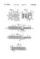
- FIG. 1is a perspective view of a segmental reduction derotation system installed on a section of spine;
- FIG. 2is a side view of a sacrum swing bolt screw
- FIG. 3is a side view of a sacrum swing bolt screw in combination with a swing bolt
- FIG. 4is a side view of a sacrum swing bolt screw in combination with a swing bolt taken along the line 4--4 of FIG. 3;
- FIG. 5is a side view of a swing bolt
- FIG. 6is a top view of a reduction block spindle assembly
- FIG. 7is a side view, in section, of a reduction block spindle assembly taken along the line 7--7 of FIG. 6;
- FIG. 8is a top view of a clamp block
- FIG. 9is a side view, in section, of the clamp block taken along line 9--9 of FIG. 8;
- FIG. 10is a top view of a pivot block
- FIG. 11is a side view, in section of the pivot block taken along line 11--11 of FIG. 10;
- FIG. 12is a top view of an adjusting spindle
- FIG. 13is a side view of the adjusting spindle taken along line 13--13 of FIG. 12;
- FIG. 14is a side view, in section of a driver clamp
- FIG. 15is a side view of an angled driver
- FIG. 16is a side view of a portion of a crimping tool
- FIG. 17is a side view of the crimping tool, taken 90° from the view of FIG. 16.
- the present inventionrelates to a segmental reduction derotation system (the system; see FIG. 1), comprising clamp assemblies 10 and reduction block spindle assemblies 12 attached to a-sacrum swing bolt screw 20 and a swing bolt 50.
- the clamp assemblies and the reduction block spindle assembliesare connected by a rod 16.
- Clamps and rods suitable for use in the present inventionare any of the clamps and rods known in the art, but of particular use are the clamps such as the incrementally angled clamps and rods described in U.S. patent application Ser. No. 08/078,724, which is incorporated herein by this reference.
- the clamps and rod togethercomprise a bracing means.
- the systemis shown, for the purpose of illustration, attached to the 5th lumbar vertebra of the spine.
- FIGS. 2-5show a sacrum swing bolt screw 20 and a swing bolt 50.
- the sacrum swing bolt screwincludes a course-threaded end 22 for placement and attachment of the system into the bony structure of the vertebra of the spine. The preferred location is determined by the surgeon and is usually through the pedicle, although other regions may be used.
- the screwmay be inserted directly into the vertebra or it may be placed in a predrilled opening, dimensioned to receive the threads of the screw firmly in an appropriate support structure of the spine.
- the configuration of the screw threadsis well known in the art and is that which is normally used for screw members intended to be implanted in bone structures.
- the upper end of the anchor screwterminates in a shoulder 24.
- the side of the shoulder distal to the threaded endincludes a pair of ears 26 disposed diametrically opposite each other on the perimeter of the shoulder.
- Each of the earsincludes an aperture 28 for insertion of swing bolt pin 29 (see FIG. 3).
- the screwis pivotally attached via the swing bolt pin to a swing bolt 50.
- the swing boltcomprises a threaded section 52 which terminates in a loop 54 having an aperture 56 extending through the loop from one side to the other perpendicular to the longitudinal axis of the swing bolt.
- the aperture of the loopwhen the swing bolt is attached to the sacrum swing bolt screw, aligns with apertures 28 forming an elongated aperture through which swing bolt pin 29 is passed to secure the swing bolt to the sacrum swing bolt screw.
- the pinis secured in place by use of a press fit relative to aperture 28.
- Aperture 56has a slightly wider diameter that of the pin so that the swing bolt can pivot about the pin.
- the reduction block spindle assemblycomprises a clamp block 80 and a pivot block 100.
- the clamp block(see FIGS. 8-9) has a generally oval shaped cross-section when viewed from the top (FIG. 8). Viewed from the side of the clamp block has a "U"-shaped cross-section and includes an ellipsoid shaped aperture 82 at the base of the "U” (see FIG. 9). Serrations 84, for grasping and mating with serrations of rod 16 are included extending lengthwise along the bottom portion of the inner wall of the ellipsoid shaped aperture. Mating of the serrations in the aperture and on the rod prevents rotation of the clamp block and the pivot block spindle assembly, relative to the rod, once the system is installed.
- Threaded apertures 86Perpendicular to, and connecting with, aperture 82 are threaded apertures 86. Threaded apertures 86 are disposed at either end of the oval shaped cross-section of the clamp block. Threaded apertures 86 each accommodate a set screw 88, which, when installed, can be tightened down against the rod to secure the clamp block to the rod. Hexagonal indentations are provided in the top surface of the heads of the set screw so that they can be tightened into place with an allen wrench driver.
- a third threaded aperture 90for accommodating retainer screw 92.
- the retainer screwsecures the clamp block to pivot block 100 when the system is installed.
- Retainer screw 92includes a thin flange 91 around the perimeter of the head of the screw (see FIG. 1).
- Flange 91extends at least partially over threaded apertures 86 and the set screws installed in the apertures and prevents the set screws from rotating out of the apertures.
- a hexagonal indentationis also provided in the top surface of the head of the retainer screw to allow it to be threaded into place with a driver.
- a recess 95is provided in the top surface of the clamp block.
- the recessis disposed adjacent to aperture 90 such that when retainer screw 92 is installed flange 91 partially overlaps the recess. After installation, and adjustment of the system is complete, flange 91 is indented into the recess.
- a protruding section 93Adjacent to aperture 90, and on one of the "long" sides of the oval shaped cross-section, is a protruding section 93.
- the protruding sectionincludes slot 94 for attaching the clamp block to pivot block 100 (see FIGS. 89). When installed, retainer screw 92 and flange 91 secure the pivot block to the clamp block.
- the pivot block 100(see FIGS. 10-11) comprises a body having a "D"-shaped cross section when viewed from the top.
- the pivot blockincludes an aperture 102 extending down through the center of the "D" shaped body.
- the internal diameter of aperture 102is stepped.
- a lower section 104has one diameter.
- Adjacent the lower sectionis an upper section 106, which has a diameter larger than that of the lower section.
- the upper sectionaccommodates the head of an adjusting spindle 120, described below, and the lower section accommodates the shaft of the adjusting spindle.
- On the flat side of the "D"-shaped pivot blockis a "T" shaped pivot 109 that is attached to the body of the pivot block at the base of the "T" and then extends outward therefrom. The pivot slides into slot 94 of the clamp block and thereby attaches the pivot block to the clamp block.
- Adjusting spindle 120(see FIGS. 12-13) has an aperture 122, which is threaded so that it mates with threaded portion 52 of swing bolt 50.
- the exterior of the adjusting spindleis of different diameters.
- the diameter of the adjusting spindleis at its smallest and this portion of the adjusting spindle extends beyond the lower edge 110 of aperture 102 in the pivot block when the spindle is inserted into that aperture.
- Adjacent to the intermediate portionis a large-diameter portion or head 128, which when the adjusting spindle is installed into aperture 102, can rotate freely into section 106 of the pivot block, thus threadably securing the pivot block to the swing bolt once an adjustable spindle flange 140, described below, is attached below the pivot block on the spindle.
- Top face 130 of the adjusting spindleincludes four radial notches 132, spaced at equal distances about the perimeter of the top face from each other. Each radial notch is located on a radius of the upper surface of the adjusting spindle. The notches align with prongs of a driver, shown in FIGS. 14 and 15 and described in detail below.
- a driveris attached to a "T" wrench for adjusting the adjusting spindle up or down the swing bolt. The driver is described in detail below.
- An adjustable spindle flange ring 140is assembled to section 124 of the adjusting spindle, after the adjusting spindle has been installed in the pivot block.
- the flange ringis then electron beam welded to the adjusting spindle.
- the adjusting spindleis retained in the pivot block, but because it is not attached to the pivot block, the adjusting spindle can freely rotate in the pivot block when it is threaded up or down on swing bolt 50. Once welded in place, the adjusting flange ring captures the spindle in the pivot block.
- the pivot blockcan be moved up or down the swing bolt by rotating the adjusting spindle in the desired direction. Adjusting the adjusting spindle up or down the swing bolt, thereby applies force via the pivot block, the swing bolt and the sacrum swing bolt screw to pull, push or rotate the vertebra to which the sacrum swing bolt screw is attached.
- a driver 141is used to rotate the adjusting spindle 120 along the swing bolt (see FIGS. 14 and 15).
- the drivercomprises a handle 142 and, at one end of the handle, a cylindrical clamp 144. At the other end of the handle is a knob 147.
- the clampcomprises two holding fingers 146, on the perimeter of the clamp to hold the adjusting spindle for installation onto the swing bolt. Between the holding fingers are four prongs 148, for aligning and mating with the four radial notches 132 of the adjusting spindle. In use an adjusting spindle is snapped into the holding fingers and prongs 148 are aligned with radial notches 132.
- the driverwith the adjusting spindle attached, is then placed on top of the swing bolt. Knob 147 is then rotated to thread the adjusting bolt onto the swing bolt and to adjust its position.
- the driver shownis angled by an angle "a" (see FIG. 15) and is useful for use with clamp assemblies which are difficult to access with a straight or non-angled driver. In another embodiment of the present invention (not shown) the driver is not angled, i.e. angle "a" is 180°. This straight driver is useful for most applications where access to the swing bolt is not limited.
- an exposed portion of wall 108(see FIG. 6) is crimped at one point along its periphery corresponding to one of the radial notches in the adjusting spindle. The crimp ensures that the adjusting spindle is firmly locked in place and that undesired rotation of the adjusting spindle is inhibited after installation of the system.
- wall 108is crimped with a tool 160 shown in FIGS. 16 and 17.
- the toolcomprises a handle 162. Attached to the handle, at one end are prongs 164 and 166. In use the prongs 166 are inserted into one set of the radial notches 132 of the adjusting spindle, and between the interior side of wall 108. Prong 164 is placed on the exterior of walls 108. The crimp is made by hitting the opposite end 168 of the handle with a hammer to thereby force prongs 166 down the wall 108 and to thereby deform the wall.
- the components of the systemare preferably made of 316 LVM stainless steel, which is electro-polished and passivated to resist corrosion by body fluids.
- the swing bolt screwscome in various lengths and diameters to accommodate the needs of the surgeon in attaching the system to particular vertebrae.
- the first step in the sequenceis to install the bracing means clamp assemblies and rods 16, 10 onto anchor screws placed in the vertebrae, or sacrum, on either side of the vertebra to be treated.
- the clamps and their placementis chosen so that when rod 16 is fastened into the clamps, clamp block 80 which is placed on the rod before hand, can be positioned at the desired alignment for attachment of the system.
- Clamp block 80is assembled on the rod before the rod is placed into the clamp assemblies.
- a sacrum swing bolt screw assemblyis then implanted into the vertebra to be treated.
- the orientation of the swing bolt, for any vertebra correctionis such that the swing bolt swings in a plane perpendicular to the linear rod (see FIG. 1) and allows the pivot block to be oriented at a correct angle to mate with the clamp block.
- the swing boltallows the sacrum swing bolt screw to be securely attached to a vertebrae, at an angle which is not perpendicular to the rod, while the swing bolt is pivoted into a position to orient the pivot 109 of the pivot block 100 to mate with the slot 94 of the clamp block 80, as described below.
- a clamp blockis then positioned on the rod, in position adjacent to the swing bolt, with the slot of the clamp block aligned with the pivot at the pivot block as the adjusting spindle is rotated down onto the swing bolt.
- the clamp blockis secured in place with set screws 88, by screwing them into threaded apertures 86 after the assembly is complete.
- the adjusting spindleis then rotated up the swing bolt to push the vertebra into position, in the case of a correction of kyphosis, or rotated down the swing bolt to pull the vertebra into position, in the case of a correction of spondylolisthesis.
- the vertebrais rotated into its correct alignment by pushing one side of the vertebra and pulling the other side of the vertebra to thereby rotate the vertebra relative to the longitudinal axis of the spine.
- wall 108is crimped to prevent rotation of the adjusting spindle, the set screws 88 are re-tightened and flange 91 is indented into recess 95 to prevent rotation of the retaining screw.
- the present inventionis not limited to the specific designs shown.
- the crimping tool and driver describedare not limited for use with the clamp assembly of the present invention. It will be clear to those skilled in the art that the crimping tool and driver could be used with other clamps which include a nut type element which includes radial notches in its upper surface. Therefore, the present invention is not intended to be limited to the working embodiments described above. The scope of the invention is defined in the following claims.
Landscapes
- Health & Medical Sciences (AREA)
- Orthopedic Medicine & Surgery (AREA)
- Surgery (AREA)
- Life Sciences & Earth Sciences (AREA)
- Heart & Thoracic Surgery (AREA)
- Nuclear Medicine, Radiotherapy & Molecular Imaging (AREA)
- Engineering & Computer Science (AREA)
- Biomedical Technology (AREA)
- Neurology (AREA)
- Medical Informatics (AREA)
- Molecular Biology (AREA)
- Animal Behavior & Ethology (AREA)
- General Health & Medical Sciences (AREA)
- Public Health (AREA)
- Veterinary Medicine (AREA)
- Surgical Instruments (AREA)
Abstract
Description
Claims (18)
Priority Applications (4)
| Application Number | Priority Date | Filing Date | Title |
|---|---|---|---|
| US08/274,971US5545166A (en) | 1994-07-14 | 1994-07-14 | Spinal segmental reduction derotational fixation system |
| US08/467,613US5649926A (en) | 1994-07-14 | 1995-06-06 | Spinal segmental reduction derotational fixation system |
| AU30962/95AAU3096295A (en) | 1994-07-14 | 1995-07-12 | Spinal segmental reduction derotational fixation system |
| PCT/US1995/008689WO1996002200A1 (en) | 1994-07-14 | 1995-07-12 | Spinal segmental reduction derotational fixation system |
Applications Claiming Priority (1)
| Application Number | Priority Date | Filing Date | Title |
|---|---|---|---|
| US08/274,971US5545166A (en) | 1994-07-14 | 1994-07-14 | Spinal segmental reduction derotational fixation system |
Related Child Applications (1)
| Application Number | Title | Priority Date | Filing Date |
|---|---|---|---|
| US08/467,613DivisionUS5649926A (en) | 1994-07-14 | 1995-06-06 | Spinal segmental reduction derotational fixation system |
Publications (1)
| Publication Number | Publication Date |
|---|---|
| US5545166Atrue US5545166A (en) | 1996-08-13 |
Family
ID=23050357
Family Applications (2)
| Application Number | Title | Priority Date | Filing Date |
|---|---|---|---|
| US08/274,971Expired - LifetimeUS5545166A (en) | 1994-07-14 | 1994-07-14 | Spinal segmental reduction derotational fixation system |
| US08/467,613Expired - Fee RelatedUS5649926A (en) | 1994-07-14 | 1995-06-06 | Spinal segmental reduction derotational fixation system |
Family Applications After (1)
| Application Number | Title | Priority Date | Filing Date |
|---|---|---|---|
| US08/467,613Expired - Fee RelatedUS5649926A (en) | 1994-07-14 | 1995-06-06 | Spinal segmental reduction derotational fixation system |
Country Status (3)
| Country | Link |
|---|---|
| US (2) | US5545166A (en) |
| AU (1) | AU3096295A (en) |
| WO (1) | WO1996002200A1 (en) |
Cited By (89)
| Publication number | Priority date | Publication date | Assignee | Title |
|---|---|---|---|---|
| US5676703A (en)* | 1994-05-11 | 1997-10-14 | Gelbard; Steven D. | Spinal stabilization implant system |
| US5876457A (en)* | 1997-05-20 | 1999-03-02 | George J. Picha | Spinal implant |
| US6123707A (en)* | 1999-01-13 | 2000-09-26 | Spinal Concepts, Inc. | Reduction instrument |
| US6217582B1 (en)* | 1996-02-23 | 2001-04-17 | D. Barclay Slocum | Joint support |
| US6248107B1 (en)* | 2000-03-15 | 2001-06-19 | Sdgi Holdings, Inc. | System for reducing the displacement of a vertebra |
| US6309391B1 (en) | 2000-03-15 | 2001-10-30 | Sdgi Holding, Inc. | Multidirectional pivoting bone screw and fixation system |
| US20020120273A1 (en)* | 1999-10-13 | 2002-08-29 | Needham Dusty Anna | Anterior cervical plating system and method |
| US20020138077A1 (en)* | 2001-03-26 | 2002-09-26 | Ferree Bret A. | Spinal alignment apparatus and methods |
| US6478798B1 (en)* | 2001-05-17 | 2002-11-12 | Robert S. Howland | Spinal fixation apparatus and methods for use |
| US20030004572A1 (en)* | 2001-03-02 | 2003-01-02 | Goble E. Marlowe | Method and apparatus for spine joint replacement |
| EP1269929A1 (en)* | 2001-06-20 | 2003-01-02 | Copf jun., Franz | Connection system for the spinal fusion of the lumbar column |
| US20030023242A1 (en)* | 1999-04-28 | 2003-01-30 | Harrington James Frederick | Modular anterior cervical plate |
| US20030105460A1 (en)* | 2000-03-15 | 2003-06-05 | Dennis Crandall | Multidirectional pivoting bone screw and fixation system |
| US6692503B2 (en) | 1999-10-13 | 2004-02-17 | Sdgi Holdings, Inc | System and method for securing a plate to the spinal column |
| US6746449B2 (en) | 2001-09-12 | 2004-06-08 | Spinal Concepts, Inc. | Spinal rod translation instrument |
| US6770075B2 (en) | 2001-05-17 | 2004-08-03 | Robert S. Howland | Spinal fixation apparatus with enhanced axial support and methods for use |
| US20040158246A1 (en)* | 1998-04-30 | 2004-08-12 | Sofamor S.N.C. | Anterior implant for the spine |
| US20040220571A1 (en)* | 1998-04-30 | 2004-11-04 | Richard Assaker | Bone plate assembly |
| US20050080486A1 (en)* | 2000-11-29 | 2005-04-14 | Fallin T. Wade | Facet joint replacement |
| WO2005044120A1 (en)* | 2002-04-24 | 2005-05-19 | Howland Robert S | Multi selective axis spinal fixation system |
| US20050149023A1 (en)* | 2001-09-28 | 2005-07-07 | Stephen Ritland | Adjustable rod and connector device and method of use |
| US20050220255A1 (en)* | 2004-01-23 | 2005-10-06 | Yann Hermouet | Storage device provided to be placed in a packaging intended for the transport of radioactive materials |
| US20050261687A1 (en)* | 2004-04-20 | 2005-11-24 | Laszlo Garamszegi | Pedicle screw assembly |
| US20050277919A1 (en)* | 2004-05-28 | 2005-12-15 | Depuy Spine, Inc. | Anchoring systems and methods for correcting spinal deformities |
| US20060074419A1 (en)* | 2004-10-05 | 2006-04-06 | Taylor Harold S | Spinal implants with multi-axial anchor assembly and methods |
| US20060084989A1 (en)* | 2004-10-05 | 2006-04-20 | Sdgi Holdings, Inc. | Multi-axial anchor assemblies for spinal implants and methods |
| US7041136B2 (en) | 2000-11-29 | 2006-05-09 | Facet Solutions, Inc. | Facet joint replacement |
| US20060149236A1 (en)* | 2004-12-30 | 2006-07-06 | Barry Mark A | System and method for aligning vertebrae in the amelioration of aberrant spinal column deviation conditions |
| US20060149231A1 (en)* | 2004-12-13 | 2006-07-06 | Rsb Spine Llc | Bone fastener assembly for bone retention apparatus |
| US20060195092A1 (en)* | 2004-12-30 | 2006-08-31 | Barry Mark A | System and method for aligning vertebrae in the amelioration of aberrant spinal column deviation conditions |
| US20060247625A1 (en)* | 2005-04-29 | 2006-11-02 | Sdgi Holdings, Inc. | System, devices and method for augmenting existing fusion constructs |
| US20070043358A1 (en)* | 2005-08-05 | 2007-02-22 | Sdgi Holdings, Inc. | Coupling assemblies for spinal implants |
| US20070072493A1 (en)* | 2004-01-27 | 2007-03-29 | Denys Sournac | Vertebral osteosynthesys device |
| US20070162006A1 (en)* | 2001-09-28 | 2007-07-12 | Stephen Ritland | Connection Rod for Screw or Hook Polyaxial System and Method of Use |
| US20070213716A1 (en)* | 2006-02-09 | 2007-09-13 | Sdgi Holdings, Inc. | Methods and instruments for spinal derotation |
| US20070213715A1 (en)* | 2006-02-09 | 2007-09-13 | Sdgi Holdings, Inc. | Spinal derotation instruments and methods |
| US20070270817A1 (en)* | 2006-04-24 | 2007-11-22 | Sdgi Holdings, Inc. | Connector apparatus |
| US20070270813A1 (en)* | 2006-04-12 | 2007-11-22 | Laszlo Garamszegi | Pedicle screw assembly |
| US20080031729A1 (en)* | 2006-08-02 | 2008-02-07 | Snecma | Cylindrical-rod device for controlling a variable-pitch vane of a turbomachine |
| US20080045953A1 (en)* | 2006-07-14 | 2008-02-21 | Laszlo Garamszegi | Pedicle screw assembly with inclined surface seat |
| US20080051789A1 (en)* | 2006-07-13 | 2008-02-28 | Snyder Brian D | Modular spinal fixation system |
| US7338526B2 (en) | 1999-03-07 | 2008-03-04 | Active Implants Corporation | Method and apparatus for computerized surgery |
| US20080177329A1 (en)* | 2006-12-28 | 2008-07-24 | Mi4Spine, Llc | Method for Providing Disc Regeneration Using Stem Cells |
| US20080306553A1 (en)* | 2007-06-05 | 2008-12-11 | Spartek Medical, Inc. | Bone anchor with a compressor element for receiving a rod for a dynamic stabilization and motion preservation spinal implantation system and method |
| US7507242B2 (en) | 2004-06-02 | 2009-03-24 | Facet Solutions | Surgical measurement and resection framework |
| US20090112269A1 (en)* | 2007-10-24 | 2009-04-30 | The Cleveland Clinic Foundation | Apparatus and method for affixing body structures |
| US7566345B1 (en) | 2001-03-01 | 2009-07-28 | Facet Solutions, Inc | Prosthesis for the replacement of a posterior element of a vertebra |
| US7588590B2 (en) | 2003-12-10 | 2009-09-15 | Facet Solutions, Inc | Spinal facet implant with spherical implant apposition surface and bone bed and methods of use |
| JP2009534167A (en)* | 2006-04-24 | 2009-09-24 | スパインフロンティア エルエルエス | Improved spinal fixation method and apparatus |
| US20090264926A1 (en)* | 2008-04-19 | 2009-10-22 | Warsaw Orthopedic, Inc. | Spinal Fixation System |
| US7625381B2 (en) | 1997-02-11 | 2009-12-01 | Warsaw Orthopedic, Inc. | System and method for stabilizing a portion of the spine |
| US7628799B2 (en) | 2005-08-23 | 2009-12-08 | Aesculap Ag & Co. Kg | Rod to rod connector |
| US7651497B2 (en) | 1997-02-11 | 2010-01-26 | Warsaw Orthopedic, Inc. | Segmentable plate with locking element |
| US20100049254A1 (en)* | 2004-03-05 | 2010-02-25 | Lutz Biedermann | Stabilization device for the dynamic stabilization of vertebrae or bones and rod like element for such a stabilization device |
| US7682375B2 (en) | 2002-05-08 | 2010-03-23 | Stephen Ritland | Dynamic fixation device and method of use |
| US7722647B1 (en) | 2005-03-14 | 2010-05-25 | Facet Solutions, Inc. | Apparatus and method for posterior vertebral stabilization |
| US7744632B2 (en) | 2006-12-20 | 2010-06-29 | Aesculap Implant Systems, Inc. | Rod to rod connector |
| US7753939B2 (en) | 2000-06-30 | 2010-07-13 | Stephen Ritland | Polyaxial connection device and method |
| US7763047B2 (en) | 2002-02-20 | 2010-07-27 | Stephen Ritland | Pedicle screw connector apparatus and method |
| US7794481B2 (en) | 2005-04-22 | 2010-09-14 | Warsaw Orthopedic, Inc. | Force limiting coupling assemblies for spinal implants |
| US7794477B2 (en) | 2004-10-05 | 2010-09-14 | Warsaw Orthopedic, Inc. | Spinal implants and methods with extended multi-axial anchor assemblies |
| WO2010108655A2 (en) | 2009-03-26 | 2010-09-30 | Franz Copf | Spine fixation system |
| US7833251B1 (en) | 2004-01-06 | 2010-11-16 | Nuvasive, Inc. | System and method for performing spinal fixation |
| US20110015677A1 (en)* | 2004-03-03 | 2011-01-20 | Biedermann Motech Gmbh | Anchoring element and stabilization device for the dynamic stabilization of vertebrae or bones using such anchoring elements |
| US7892265B2 (en) | 2006-12-28 | 2011-02-22 | Mi4Spine, Llc | Surgical screw including a body that facilitates bone in-growth |
| US20110106082A1 (en)* | 2009-10-30 | 2011-05-05 | Warsaw Orthopedic, Inc. | Instruments and systems for vertebral column manipulation |
| WO2011057178A1 (en) | 2009-11-06 | 2011-05-12 | Dean Lin | System and method for stabilizing and fixating lumbar vertebrae |
| US7993373B2 (en) | 2005-02-22 | 2011-08-09 | Hoy Robert W | Polyaxial orthopedic fastening apparatus |
| US8021399B2 (en) | 2005-07-19 | 2011-09-20 | Stephen Ritland | Rod extension for extending fusion construct |
| US8206418B2 (en) | 2007-01-10 | 2012-06-26 | Gmedelaware 2 Llc | System and method for facet joint replacement with detachable coupler |
| US8211152B2 (en) | 2007-02-28 | 2012-07-03 | Mass Modular Spine Group, Inc. | Tension fixation system |
| US8562649B2 (en) | 2004-02-17 | 2013-10-22 | Gmedelaware 2 Llc | System and method for multiple level facet joint arthroplasty and fusion |
| US8764801B2 (en) | 2005-03-28 | 2014-07-01 | Gmedelaware 2 Llc | Facet joint implant crosslinking apparatus and method |
| US8771319B2 (en) | 2012-04-16 | 2014-07-08 | Aesculap Implant Systems, Llc | Rod to rod cross connector |
| US8828056B2 (en) | 2012-04-16 | 2014-09-09 | Aesculap Implant Systems, Llc | Rod to rod cross connector |
| US8900273B2 (en) | 2005-02-22 | 2014-12-02 | Gmedelaware 2 Llc | Taper-locking fixation system |
| US8920473B2 (en) | 2006-12-10 | 2014-12-30 | Paradigm Spine, Llc | Posterior functionally dynamic stabilization system |
| US8932334B2 (en) | 2002-04-05 | 2015-01-13 | Stephen Ritland | Dynamic fixation device and method of use |
| US8986349B1 (en) | 2009-11-11 | 2015-03-24 | Nuvasive, Inc. | Systems and methods for correcting spinal deformities |
| US9060813B1 (en) | 2008-02-29 | 2015-06-23 | Nuvasive, Inc. | Surgical fixation system and related methods |
| US9179957B2 (en) | 2012-08-09 | 2015-11-10 | Spinecraft, LLC | Systems, assemblies and methods for spinal derotation |
| US9198696B1 (en) | 2010-05-27 | 2015-12-01 | Nuvasive, Inc. | Cross-connector and related methods |
| US9247964B1 (en) | 2011-03-01 | 2016-02-02 | Nuasive, Inc. | Spinal Cross-connector |
| US9339301B2 (en) | 2004-12-30 | 2016-05-17 | Mark A. Barry | System and method for aligning vertebrae in the amelioration of aberrant spinal column deviation conditions |
| US9387013B1 (en) | 2011-03-01 | 2016-07-12 | Nuvasive, Inc. | Posterior cervical fixation system |
| US9668789B2 (en) | 2013-03-15 | 2017-06-06 | Ebi, Llc | Reduction instrument, surgical assembly including a reduction instrument and related method |
| US9861393B2 (en) | 2012-08-09 | 2018-01-09 | Spinecraft, LLC | Systems, assemblies and methods for spinal derotation |
| US11219531B2 (en) | 2019-04-10 | 2022-01-11 | Wenzel Spine, Inc. | Rotatable intervertebral spacing implant |
| US11331125B1 (en) | 2021-10-07 | 2022-05-17 | Ortho Inventions, Llc | Low profile rod-to-rod coupler |
Families Citing this family (62)
| Publication number | Priority date | Publication date | Assignee | Title |
|---|---|---|---|---|
| US5674296A (en) | 1994-11-14 | 1997-10-07 | Spinal Dynamics Corporation | Human spinal disc prosthesis |
| US6019759A (en)* | 1996-07-29 | 2000-02-01 | Rogozinski; Chaim | Multi-Directional fasteners or attachment devices for spinal implant elements |
| EP0888754A1 (en)* | 1997-07-03 | 1999-01-07 | Acromed Corporation | Osteosynthetic Fastener |
| US5899902A (en)* | 1997-07-03 | 1999-05-04 | Depuy Motech Acromed Corporation | Fastener |
| WO2000004851A1 (en) | 1998-07-22 | 2000-02-03 | Spinal Dynamics Corporation | Threaded cylindrical multidiscoid single or multiple array disc prosthesis |
| WO2000013619A1 (en)* | 1998-09-04 | 2000-03-16 | Spinal Dynamics Corporation | Peanut spectacle multi discoid thoraco-lumbar disc prosthesis |
| US6749635B1 (en) | 1998-09-04 | 2004-06-15 | Sdgi Holdings, Inc. | Peanut spectacle multi discoid thoraco-lumbar disc prosthesis |
| US7998213B2 (en) | 1999-08-18 | 2011-08-16 | Intrinsic Therapeutics, Inc. | Intervertebral disc herniation repair |
| CA2425951C (en)* | 1999-08-18 | 2008-09-16 | Intrinsic Therapeutics, Inc. | Devices and method for nucleus pulposus augmentation and retention |
| US7094258B2 (en) | 1999-08-18 | 2006-08-22 | Intrinsic Therapeutics, Inc. | Methods of reinforcing an annulus fibrosis |
| US7972337B2 (en) | 2005-12-28 | 2011-07-05 | Intrinsic Therapeutics, Inc. | Devices and methods for bone anchoring |
| EP1624832A4 (en) | 1999-08-18 | 2008-12-24 | Intrinsic Therapeutics Inc | Devices and method for augmenting a vertebral disc nucleus |
| US7717961B2 (en) | 1999-08-18 | 2010-05-18 | Intrinsic Therapeutics, Inc. | Apparatus delivery in an intervertebral disc |
| US8323341B2 (en) | 2007-09-07 | 2012-12-04 | Intrinsic Therapeutics, Inc. | Impaction grafting for vertebral fusion |
| JP2004516044A (en) | 2000-08-08 | 2004-06-03 | エスディージーアイ・ホールディングス・インコーポレーテッド | Method and apparatus for improving stereotactic body transplantation |
| CA2429246C (en) | 2000-08-08 | 2011-06-07 | Vincent Bryan | Implantable joint prosthesis |
| US7601174B2 (en)* | 2000-08-08 | 2009-10-13 | Warsaw Orthopedic, Inc. | Wear-resistant endoprosthetic devices |
| US7125380B2 (en)* | 2000-08-08 | 2006-10-24 | Warsaw Orthopedic, Inc. | Clamping apparatus and methods |
| US6554831B1 (en)* | 2000-09-01 | 2003-04-29 | Hopital Sainte-Justine | Mobile dynamic system for treating spinal disorder |
| US6565605B2 (en)* | 2000-12-13 | 2003-05-20 | Medicinelodge, Inc. | Multiple facet joint replacement |
| US6562045B2 (en) | 2001-02-13 | 2003-05-13 | Sdgi Holdings, Inc. | Machining apparatus |
| US7144413B2 (en) | 2001-04-20 | 2006-12-05 | Synthes (U.S.A.) | Graft fixation system and method |
| US20040243128A1 (en)* | 2001-05-17 | 2004-12-02 | Howland Robert S. | Selective axis posterior lumbar spinal plating fixation apparatus and methods for use |
| US7025787B2 (en)* | 2001-11-26 | 2006-04-11 | Sdgi Holdings, Inc. | Implantable joint prosthesis and associated instrumentation |
| JP2005512670A (en)* | 2001-12-09 | 2005-05-12 | ユニバーシティ カレッジ ロンドン | Articulated vertebral fixation device |
| US8029548B2 (en)* | 2008-05-05 | 2011-10-04 | Warsaw Orthopedic, Inc. | Flexible spinal stabilization element and system |
| US7618418B2 (en)* | 2004-04-16 | 2009-11-17 | Kyphon Sarl | Plate system for minimally invasive support of the spine |
| US7789899B2 (en)* | 2004-12-30 | 2010-09-07 | Warsaw Orthopedic, Inc. | Bone anchorage screw with built-in hinged plate |
| EP1740112A1 (en)* | 2004-04-16 | 2007-01-10 | Kyphon Inc. | Screw assembly |
| US7648520B2 (en)* | 2004-04-16 | 2010-01-19 | Kyphon Sarl | Pedicle screw assembly |
| US7524323B2 (en)* | 2004-04-16 | 2009-04-28 | Kyphon Sarl | Subcutaneous support |
| US7811311B2 (en)* | 2004-12-30 | 2010-10-12 | Warsaw Orthopedic, Inc. | Screw with deployable interlaced dual rods |
| FR2870713B1 (en)* | 2004-05-26 | 2006-09-01 | Sdgi Holdings Inc | IMPLANT FOR OSTEOSYNTHESIS DEVICE OF THE RACHIS, AND TOGETHER FORMED BY THIS IMPLANT, A CONNECTOR AND AN NUT |
| US7850719B2 (en)* | 2004-05-26 | 2010-12-14 | Warsaw Orthopedic, Inc. | Spinal implant apparatus |
| FR2870712B1 (en)* | 2004-05-26 | 2006-09-01 | Sdgi Holdings Inc | IMPLANTS FOR SPINAL OSTEOSYNTHESIS DEVICE AND TOOL COMPRISING SAME |
| US7658753B2 (en)* | 2004-08-03 | 2010-02-09 | K Spine, Inc. | Device and method for correcting a spinal deformity |
| US8114158B2 (en) | 2004-08-03 | 2012-02-14 | Kspine, Inc. | Facet device and method |
| CA2614898C (en) | 2005-04-27 | 2014-04-22 | Trinity Orthopedics, Llc | Mono-planar pedilcle screw method, system, and kit |
| US8083773B2 (en)* | 2005-07-15 | 2011-12-27 | Muhammad Abubakar Atiq Durrani | Apparatus for minimally invasive posterior correction of spinal deformity |
| US8029547B2 (en)* | 2007-01-30 | 2011-10-04 | Warsaw Orthopedic, Inc. | Dynamic spinal stabilization assembly with sliding collars |
| US8109975B2 (en)* | 2007-01-30 | 2012-02-07 | Warsaw Orthopedic, Inc. | Collar bore configuration for dynamic spinal stabilization assembly |
| EP2301456B1 (en)* | 2007-02-23 | 2013-04-17 | Biedermann Technologies GmbH & Co. KG | Rod connector for stabilizing vertebrae |
| EP2155086B1 (en) | 2007-06-06 | 2016-05-04 | K2M, Inc. | Medical device to correct deformity |
| US20110196492A1 (en) | 2007-09-07 | 2011-08-11 | Intrinsic Therapeutics, Inc. | Bone anchoring systems |
| US8298266B2 (en)* | 2008-04-11 | 2012-10-30 | Warsaw Orthopedic, Inc. | Connectors for elongated surgical members and methods of use |
| US20090264933A1 (en)* | 2008-04-22 | 2009-10-22 | Warsaw Orthopedic, Inc. | Anchors for securing a rod to a vertebral member |
| US8828058B2 (en) | 2008-11-11 | 2014-09-09 | Kspine, Inc. | Growth directed vertebral fixation system with distractible connector(s) and apical control |
| US8357182B2 (en) | 2009-03-26 | 2013-01-22 | Kspine, Inc. | Alignment system with longitudinal support features |
| US8236035B1 (en) | 2009-06-16 | 2012-08-07 | Bedor Bernard M | Spinal fixation system and method |
| US9168071B2 (en) | 2009-09-15 | 2015-10-27 | K2M, Inc. | Growth modulation system |
| US20110087292A1 (en) | 2009-10-14 | 2011-04-14 | K2M, Inc. | Occipital fixation assembly, system and method for attaching the same |
| JP6158176B2 (en) | 2011-06-03 | 2017-07-05 | ケイツーエム インコーポレイテッドK2M,Inc. | Spine correction system |
| US9468469B2 (en) | 2011-11-16 | 2016-10-18 | K2M, Inc. | Transverse coupler adjuster spinal correction systems and methods |
| WO2014172632A2 (en) | 2011-11-16 | 2014-10-23 | Kspine, Inc. | Spinal correction and secondary stabilization |
| US9451987B2 (en) | 2011-11-16 | 2016-09-27 | K2M, Inc. | System and method for spinal correction |
| US9468468B2 (en) | 2011-11-16 | 2016-10-18 | K2M, Inc. | Transverse connector for spinal stabilization system |
| US8920472B2 (en) | 2011-11-16 | 2014-12-30 | Kspine, Inc. | Spinal correction and secondary stabilization |
| US9468471B2 (en) | 2013-09-17 | 2016-10-18 | K2M, Inc. | Transverse coupler adjuster spinal correction systems and methods |
| US9788867B2 (en) | 2013-11-05 | 2017-10-17 | Warsaw Orthopedic, Inc. | Spinal correction system and method |
| US9877846B2 (en) | 2015-01-20 | 2018-01-30 | Warsaw Orthopedic, Inc. | Spinal implant system and method |
| US10966839B2 (en) | 2017-06-30 | 2021-04-06 | Warsaw Orthopedic, Inc. | Spinal implant system and method |
| US10966736B2 (en) | 2018-05-21 | 2021-04-06 | Warsaw Orthopedic, Inc. | Spinal implant system and methods of use |
Citations (6)
| Publication number | Priority date | Publication date | Assignee | Title |
|---|---|---|---|---|
| US2696817A (en)* | 1952-04-30 | 1954-12-14 | Samuel B Prevo | Prosthetic elbow joint |
| US5034011A (en)* | 1990-08-09 | 1991-07-23 | Advanced Spine Fixation Systems Incorporated | Segmental instrumentation of the posterior spine |
| US5047029A (en)* | 1988-06-10 | 1991-09-10 | Synthes (U.S.A.) | Clamp and system for internal fixation |
| US5053034A (en)* | 1990-08-03 | 1991-10-01 | Sven Olerud | Spinal joint |
| US5129900A (en)* | 1990-07-24 | 1992-07-14 | Acromed Corporation | Spinal column retaining method and apparatus |
| US5254118A (en)* | 1991-12-04 | 1993-10-19 | Srdjian Mirkovic | Three dimensional spine fixation system |
- 1994
- 1994-07-14USUS08/274,971patent/US5545166A/ennot_activeExpired - Lifetime
- 1995
- 1995-06-06USUS08/467,613patent/US5649926A/ennot_activeExpired - Fee Related
- 1995-07-12WOPCT/US1995/008689patent/WO1996002200A1/enactiveApplication Filing
- 1995-07-12AUAU30962/95Apatent/AU3096295A/ennot_activeAbandoned
Patent Citations (7)
| Publication number | Priority date | Publication date | Assignee | Title |
|---|---|---|---|---|
| US2696817A (en)* | 1952-04-30 | 1954-12-14 | Samuel B Prevo | Prosthetic elbow joint |
| US5047029A (en)* | 1988-06-10 | 1991-09-10 | Synthes (U.S.A.) | Clamp and system for internal fixation |
| US5129900A (en)* | 1990-07-24 | 1992-07-14 | Acromed Corporation | Spinal column retaining method and apparatus |
| US5129900B1 (en)* | 1990-07-24 | 1998-12-29 | Acromed Corp | Spinal column retaining method and apparatus |
| US5053034A (en)* | 1990-08-03 | 1991-10-01 | Sven Olerud | Spinal joint |
| US5034011A (en)* | 1990-08-09 | 1991-07-23 | Advanced Spine Fixation Systems Incorporated | Segmental instrumentation of the posterior spine |
| US5254118A (en)* | 1991-12-04 | 1993-10-19 | Srdjian Mirkovic | Three dimensional spine fixation system |
Cited By (213)
| Publication number | Priority date | Publication date | Assignee | Title |
|---|---|---|---|---|
| US5676703A (en)* | 1994-05-11 | 1997-10-14 | Gelbard; Steven D. | Spinal stabilization implant system |
| US7491219B2 (en) | 1995-09-04 | 2009-02-17 | Active Implants Corporation | Method and apparatus for computerized surgery |
| US7497868B2 (en) | 1995-09-04 | 2009-03-03 | Active Implants Corporation | Method and apparatus for computerized surgery |
| US6464705B2 (en) | 1996-02-23 | 2002-10-15 | D. Barclay Slocum Trust Agreement | Joint support |
| US6217582B1 (en)* | 1996-02-23 | 2001-04-17 | D. Barclay Slocum | Joint support |
| US8641743B2 (en) | 1997-02-11 | 2014-02-04 | Warsaw Orthopedic, Inc. | Orthopedic implant with locking element |
| US8123788B2 (en) | 1997-02-11 | 2012-02-28 | Warsaw Orthopedic, Inc. | Plating system having retaining member that permits movement of at least one bone fastener |
| US7651497B2 (en) | 1997-02-11 | 2010-01-26 | Warsaw Orthopedic, Inc. | Segmentable plate with locking element |
| US7625381B2 (en) | 1997-02-11 | 2009-12-01 | Warsaw Orthopedic, Inc. | System and method for stabilizing a portion of the spine |
| US7704255B2 (en) | 1997-02-11 | 2010-04-27 | Warsaw Orthopedic, Inc. | Threadless multi-lock anterior cervical plating system |
| US8480717B2 (en) | 1997-02-11 | 2013-07-09 | Warsaw Orthopedic, Inc. | Orthopedic implant with locking element |
| US8048075B2 (en) | 1997-02-11 | 2011-11-01 | Warsaw Orthopedic, Inc. | Orthopedic implant with locking element |
| US8262708B2 (en) | 1997-02-11 | 2012-09-11 | Warsaw Orthopedic, Inc. | Single-lock plating system |
| US6071310A (en)* | 1997-05-20 | 2000-06-06 | George J. Picha | Spinal implant |
| US6346122B1 (en) | 1997-05-20 | 2002-02-12 | George J. Picha | Spinal implant |
| US5876457A (en)* | 1997-05-20 | 1999-03-02 | George J. Picha | Spinal implant |
| US7556648B2 (en) | 1997-05-20 | 2009-07-07 | George J. Picha | Spinal implant |
| US8016864B2 (en) | 1998-04-30 | 2011-09-13 | Warsaw Orthopedic, Inc. | Anterior implant for the spine |
| US20040158246A1 (en)* | 1998-04-30 | 2004-08-12 | Sofamor S.N.C. | Anterior implant for the spine |
| US20040220571A1 (en)* | 1998-04-30 | 2004-11-04 | Richard Assaker | Bone plate assembly |
| US20100069968A1 (en)* | 1998-04-30 | 2010-03-18 | Sofamor S.N.C. | Anterior implant for the spine |
| US6123707A (en)* | 1999-01-13 | 2000-09-26 | Spinal Concepts, Inc. | Reduction instrument |
| US9827109B2 (en) | 1999-03-07 | 2017-11-28 | Nuvasive, Inc. | Methods and apparatus for performing spine surgery |
| US7338526B2 (en) | 1999-03-07 | 2008-03-04 | Active Implants Corporation | Method and apparatus for computerized surgery |
| US9668875B2 (en) | 1999-03-07 | 2017-06-06 | Nuvasive, Inc. | Method and apparatus for computerized surgery |
| US9017313B2 (en) | 1999-03-07 | 2015-04-28 | Nuvasive, Inc. | Method and apparatus for computerized surgery |
| US6855147B2 (en) | 1999-04-28 | 2005-02-15 | James Frederick Harrington, Jr. | Modular anterior cervical plate |
| US20030023242A1 (en)* | 1999-04-28 | 2003-01-30 | Harrington James Frederick | Modular anterior cervical plate |
| US8167919B2 (en) | 1999-10-13 | 2012-05-01 | Warsaw Orthopedic, Inc. | System and method for securing a plate to the spinal column |
| US6692503B2 (en) | 1999-10-13 | 2004-02-17 | Sdgi Holdings, Inc | System and method for securing a plate to the spinal column |
| US6533786B1 (en) | 1999-10-13 | 2003-03-18 | Sdgi Holdings, Inc. | Anterior cervical plating system |
| US20020120273A1 (en)* | 1999-10-13 | 2002-08-29 | Needham Dusty Anna | Anterior cervical plating system and method |
| US20090326590A1 (en)* | 1999-10-13 | 2009-12-31 | Warsaw Orthopedic, Inc. | System and method for securing a plate to the spinal column |
| US20030105460A1 (en)* | 2000-03-15 | 2003-06-05 | Dennis Crandall | Multidirectional pivoting bone screw and fixation system |
| US7322979B2 (en) | 2000-03-15 | 2008-01-29 | Warsaw Orthopedic, Inc. | Multidirectional pivoting bone screw and fixation system |
| US6248107B1 (en)* | 2000-03-15 | 2001-06-19 | Sdgi Holdings, Inc. | System for reducing the displacement of a vertebra |
| US6309391B1 (en) | 2000-03-15 | 2001-10-30 | Sdgi Holding, Inc. | Multidirectional pivoting bone screw and fixation system |
| US7753939B2 (en) | 2000-06-30 | 2010-07-13 | Stephen Ritland | Polyaxial connection device and method |
| US7618453B2 (en) | 2000-11-29 | 2009-11-17 | Facet Solutions, Inc | Facet joint replacement |
| US7041136B2 (en) | 2000-11-29 | 2006-05-09 | Facet Solutions, Inc. | Facet joint replacement |
| US8313511B2 (en) | 2000-11-29 | 2012-11-20 | Gmedelaware 2 Llc | Facet joint replacement |
| US7621955B2 (en) | 2000-11-29 | 2009-11-24 | Facet Solutions, Inc. | Facet joint replacement |
| US20050080486A1 (en)* | 2000-11-29 | 2005-04-14 | Fallin T. Wade | Facet joint replacement |
| US7566345B1 (en) | 2001-03-01 | 2009-07-28 | Facet Solutions, Inc | Prosthesis for the replacement of a posterior element of a vertebra |
| US7955390B2 (en) | 2001-03-02 | 2011-06-07 | GME Delaware 2 LLC | Method and apparatus for spine joint replacement |
| US20030004572A1 (en)* | 2001-03-02 | 2003-01-02 | Goble E. Marlowe | Method and apparatus for spine joint replacement |
| US7445635B2 (en) | 2001-03-02 | 2008-11-04 | Facet Solutions | Method and apparatus for spine joint replacement |
| US7090698B2 (en) | 2001-03-02 | 2006-08-15 | Facet Solutions | Method and apparatus for spine joint replacement |
| US6802844B2 (en) | 2001-03-26 | 2004-10-12 | Nuvasive, Inc | Spinal alignment apparatus and methods |
| US20020138077A1 (en)* | 2001-03-26 | 2002-09-26 | Ferree Bret A. | Spinal alignment apparatus and methods |
| US20040260287A1 (en)* | 2001-03-26 | 2004-12-23 | Nuvasive, Inc. | Spinal alignment system and related methods |
| US20080071275A1 (en)* | 2001-03-26 | 2008-03-20 | Nu Vasive, Inc. | Spinal alignment system and related methods |
| US6478798B1 (en)* | 2001-05-17 | 2002-11-12 | Robert S. Howland | Spinal fixation apparatus and methods for use |
| US6770075B2 (en) | 2001-05-17 | 2004-08-03 | Robert S. Howland | Spinal fixation apparatus with enhanced axial support and methods for use |
| EP1269929A1 (en)* | 2001-06-20 | 2003-01-02 | Copf jun., Franz | Connection system for the spinal fusion of the lumbar column |
| US6746449B2 (en) | 2001-09-12 | 2004-06-08 | Spinal Concepts, Inc. | Spinal rod translation instrument |
| US9622790B2 (en) | 2001-09-19 | 2017-04-18 | Warsaw Orthopedic, Inc. | Rod extension for extending fusion construct |
| US20070162006A1 (en)* | 2001-09-28 | 2007-07-12 | Stephen Ritland | Connection Rod for Screw or Hook Polyaxial System and Method of Use |
| US20100137914A1 (en)* | 2001-09-28 | 2010-06-03 | Stephen Ritland | Adjustable rod and connector device |
| US7655025B2 (en) | 2001-09-28 | 2010-02-02 | Stephen Ritland | Adjustable rod and connector device and method of use |
| US7985245B2 (en) | 2001-09-28 | 2011-07-26 | Stephen Ritland | Connection rod for screw or hook polyaxial system and method of use |
| US20050149023A1 (en)* | 2001-09-28 | 2005-07-07 | Stephen Ritland | Adjustable rod and connector device and method of use |
| US7695498B2 (en)* | 2001-09-28 | 2010-04-13 | Stephen Ritland | Connection rod for screw or hook polyaxial system and method of use |
| US20110022094A1 (en)* | 2002-02-20 | 2011-01-27 | Stephen Ritland | Pedicle Screw Connector Apparatus and Method |
| US7763047B2 (en) | 2002-02-20 | 2010-07-27 | Stephen Ritland | Pedicle screw connector apparatus and method |
| US8221459B2 (en) | 2002-02-20 | 2012-07-17 | Stephen Ritland | Pedicle screw connector apparatus and method |
| US8932334B2 (en) | 2002-04-05 | 2015-01-13 | Stephen Ritland | Dynamic fixation device and method of use |
| US7314467B2 (en) | 2002-04-24 | 2008-01-01 | Medical Device Advisory Development Group, Llc. | Multi selective axis spinal fixation system |
| WO2005044120A1 (en)* | 2002-04-24 | 2005-05-19 | Howland Robert S | Multi selective axis spinal fixation system |
| US8685062B2 (en) | 2002-05-08 | 2014-04-01 | Stephen Ritland | Dynamic fixation device and method of use |
| US20100174318A1 (en)* | 2002-05-08 | 2010-07-08 | Stephen Ritland | Dynamic Fixation Device and Method of Use |
| US9918744B2 (en) | 2002-05-08 | 2018-03-20 | Stephen Ritland | Dynamic fixation device and method of use |
| US8690922B2 (en) | 2002-05-08 | 2014-04-08 | Stephen Ritland | Dynamic fixation device and method of use |
| US7682375B2 (en) | 2002-05-08 | 2010-03-23 | Stephen Ritland | Dynamic fixation device and method of use |
| US20100179596A1 (en)* | 2002-05-08 | 2010-07-15 | Stephen Ritland | Dynamic Fixation Device and Method of Use |
| US8486111B2 (en) | 2002-05-08 | 2013-07-16 | Stephen Ritland | Dynamic fixation device and method of use |
| US8585739B2 (en) | 2002-05-08 | 2013-11-19 | Stephen Ritland | Dynamic fixation device and method of use |
| US9232967B2 (en) | 2002-05-08 | 2016-01-12 | Stephen Ritland | Dynamic fixation device and method of use |
| US8419770B2 (en) | 2003-12-10 | 2013-04-16 | Gmedelaware 2 Llc | Spinal facet implants with mating articulating bearing surface and methods of use |
| US7753937B2 (en) | 2003-12-10 | 2010-07-13 | Facet Solutions Inc. | Linked bilateral spinal facet implants and methods of use |
| US8926700B2 (en) | 2003-12-10 | 2015-01-06 | Gmedelware 2 LLC | Spinal facet joint implant |
| US7588590B2 (en) | 2003-12-10 | 2009-09-15 | Facet Solutions, Inc | Spinal facet implant with spherical implant apposition surface and bone bed and methods of use |
| US7833251B1 (en) | 2004-01-06 | 2010-11-16 | Nuvasive, Inc. | System and method for performing spinal fixation |
| US20050220255A1 (en)* | 2004-01-23 | 2005-10-06 | Yann Hermouet | Storage device provided to be placed in a packaging intended for the transport of radioactive materials |
| US20070072493A1 (en)* | 2004-01-27 | 2007-03-29 | Denys Sournac | Vertebral osteosynthesys device |
| US8579941B2 (en) | 2004-02-17 | 2013-11-12 | Alan Chervitz | Linked bilateral spinal facet implants and methods of use |
| US8906063B2 (en) | 2004-02-17 | 2014-12-09 | Gmedelaware 2 Llc | Spinal facet joint implant |
| US8562649B2 (en) | 2004-02-17 | 2013-10-22 | Gmedelaware 2 Llc | System and method for multiple level facet joint arthroplasty and fusion |
| US7914560B2 (en) | 2004-02-17 | 2011-03-29 | Gmedelaware 2 Llc | Spinal facet implant with spherical implant apposition surface and bone bed and methods of use |
| US7998177B2 (en) | 2004-02-17 | 2011-08-16 | Gmedelaware 2 Llc | Linked bilateral spinal facet implants and methods of use |
| US7998178B2 (en) | 2004-02-17 | 2011-08-16 | Gmedelaware 2 Llc | Linked bilateral spinal facet implants and methods of use |
| US9282999B2 (en)* | 2004-03-03 | 2016-03-15 | Biedermann Technologies Gmbh & Co. Kg | Anchoring element and stabilization device for the dynamic stabilization of vertebrae or bones using such anchoring elements |
| US20110015677A1 (en)* | 2004-03-03 | 2011-01-20 | Biedermann Motech Gmbh | Anchoring element and stabilization device for the dynamic stabilization of vertebrae or bones using such anchoring elements |
| US8257400B2 (en)* | 2004-03-05 | 2012-09-04 | Biedermann Technologies Gmbh & Co. Kg | Stabilization device for the dynamic stabilization of vertebrae or bones and rod like element for such a stabilization device |
| US20100049254A1 (en)* | 2004-03-05 | 2010-02-25 | Lutz Biedermann | Stabilization device for the dynamic stabilization of vertebrae or bones and rod like element for such a stabilization device |
| US8273112B2 (en) | 2004-04-20 | 2012-09-25 | Phygen, Llc | Pedicle screw assembly |
| US20050261687A1 (en)* | 2004-04-20 | 2005-11-24 | Laszlo Garamszegi | Pedicle screw assembly |
| US7678139B2 (en) | 2004-04-20 | 2010-03-16 | Allez Spine, Llc | Pedicle screw assembly |
| US20100292740A1 (en)* | 2004-04-20 | 2010-11-18 | Laszlo Garamszegi | Pedicle screw assembly |
| US8992578B2 (en) | 2004-05-28 | 2015-03-31 | Depuy Synthes Products Llc | Anchoring systems and methods for correcting spinal deformities |
| US20050277919A1 (en)* | 2004-05-28 | 2005-12-15 | Depuy Spine, Inc. | Anchoring systems and methods for correcting spinal deformities |
| US20110077688A1 (en)* | 2004-05-28 | 2011-03-31 | Depuy Spine, Inc. | Anchoring systems and methods for correcting spinal deformities |
| US8540754B2 (en) | 2004-05-28 | 2013-09-24 | DePuy Synthes Products, LLC | Anchoring systems and methods for correcting spinal deformities |
| US7901435B2 (en)* | 2004-05-28 | 2011-03-08 | Depuy Spine, Inc. | Anchoring systems and methods for correcting spinal deformities |
| US7815648B2 (en) | 2004-06-02 | 2010-10-19 | Facet Solutions, Inc | Surgical measurement systems and methods |
| US7507242B2 (en) | 2004-06-02 | 2009-03-24 | Facet Solutions | Surgical measurement and resection framework |
| US7588578B2 (en) | 2004-06-02 | 2009-09-15 | Facet Solutions, Inc | Surgical measurement systems and methods |
| US8777994B2 (en) | 2004-06-02 | 2014-07-15 | Gmedelaware 2 Llc | System and method for multiple level facet joint arthroplasty and fusion |
| US8361125B2 (en) | 2004-10-05 | 2013-01-29 | Warsaw Orthopedic, Inc. | Spinal implants with multi-axial anchor assembly and methods |
| US20060084989A1 (en)* | 2004-10-05 | 2006-04-20 | Sdgi Holdings, Inc. | Multi-axial anchor assemblies for spinal implants and methods |
| US20100318132A1 (en)* | 2004-10-05 | 2010-12-16 | Warsaw Orthopedic, Inc. | Spinal Implants and Methods With Extended Multi-Axial Anchor Assemblies |
| US7794477B2 (en) | 2004-10-05 | 2010-09-14 | Warsaw Orthopedic, Inc. | Spinal implants and methods with extended multi-axial anchor assemblies |
| US7722654B2 (en) | 2004-10-05 | 2010-05-25 | Warsaw Orthopedic, Inc. | Spinal implants with multi-axial anchor assembly and methods |
| US8012188B2 (en) | 2004-10-05 | 2011-09-06 | Warsaw Orthopedic, Inc. | Spinal implants and methods with extended multi-axial anchor assemblies |
| US20100198269A1 (en)* | 2004-10-05 | 2010-08-05 | Warsaw Orthopedic, Inc. | Spinal Implants with Multi-Axial Anchor Assembly and Methods |
| US20060074419A1 (en)* | 2004-10-05 | 2006-04-06 | Taylor Harold S | Spinal implants with multi-axial anchor assembly and methods |
| US7572280B2 (en) | 2004-10-05 | 2009-08-11 | Warsaw Orthopedic, Inc. | Multi-axial anchor assemblies for spinal implants and methods |
| US20060149231A1 (en)* | 2004-12-13 | 2006-07-06 | Rsb Spine Llc | Bone fastener assembly for bone retention apparatus |
| US7578833B2 (en) | 2004-12-13 | 2009-08-25 | Dr. Robert S. Bray, Jr. | Bone fastener assembly for bone retention apparatus |
| US8361121B2 (en) | 2004-12-30 | 2013-01-29 | Barry Mark A | System and method for aligning vertebrae in the amelioration of aberrant spinal column deviation conditions |
| US9339301B2 (en) | 2004-12-30 | 2016-05-17 | Mark A. Barry | System and method for aligning vertebrae in the amelioration of aberrant spinal column deviation conditions |
| US9668788B2 (en) | 2004-12-30 | 2017-06-06 | Mark A. Barry | System and method for aligning vertebrae in the amelioration of aberrant spinal column deviation conditions |
| US7776072B2 (en) | 2004-12-30 | 2010-08-17 | Barry Mark A | System and method for aligning vertebrae in the amelioration of aberrant spinal column deviation conditions |
| US7670358B2 (en) | 2004-12-30 | 2010-03-02 | Barry Mark A | System and method for aligning vertebrae in the amelioration of aberrant spinal column deviation conditions |
| US20060149236A1 (en)* | 2004-12-30 | 2006-07-06 | Barry Mark A | System and method for aligning vertebrae in the amelioration of aberrant spinal column deviation conditions |
| US9668787B2 (en) | 2004-12-30 | 2017-06-06 | Mark A. Barry | System and method for aligning vertebrae in the amelioration of aberrant spinal column deviation conditions |
| US20060195092A1 (en)* | 2004-12-30 | 2006-08-31 | Barry Mark A | System and method for aligning vertebrae in the amelioration of aberrant spinal column deviation conditions |
| US10765460B2 (en) | 2004-12-30 | 2020-09-08 | Mark A. Barry | System and method for aligning vertebrae in the amelioration of aberrant spinal column deviation conditions |
| US8062336B2 (en) | 2005-02-22 | 2011-11-22 | Gmedelaware 2 Llc | Polyaxial orthopedic fastening apparatus with independent locking modes |
| US7993373B2 (en) | 2005-02-22 | 2011-08-09 | Hoy Robert W | Polyaxial orthopedic fastening apparatus |
| US8900273B2 (en) | 2005-02-22 | 2014-12-02 | Gmedelaware 2 Llc | Taper-locking fixation system |
| US7722647B1 (en) | 2005-03-14 | 2010-05-25 | Facet Solutions, Inc. | Apparatus and method for posterior vertebral stabilization |
| US8764801B2 (en) | 2005-03-28 | 2014-07-01 | Gmedelaware 2 Llc | Facet joint implant crosslinking apparatus and method |
| US7794481B2 (en) | 2005-04-22 | 2010-09-14 | Warsaw Orthopedic, Inc. | Force limiting coupling assemblies for spinal implants |
| US20100198265A1 (en)* | 2005-04-29 | 2010-08-05 | Morrison Matthew M | System, Devices and method for augmenting existing fusion constructs |
| US20060247625A1 (en)* | 2005-04-29 | 2006-11-02 | Sdgi Holdings, Inc. | System, devices and method for augmenting existing fusion constructs |
| US7695499B2 (en) | 2005-04-29 | 2010-04-13 | Warsaw Orthopedic, Inc. | System, devices and method for augmenting existing fusion constructs |
| US8845694B2 (en) | 2005-07-19 | 2014-09-30 | Warsaw Orthopedic, Inc. | Rod extension for extending fusion construct |
| US8021399B2 (en) | 2005-07-19 | 2011-09-20 | Stephen Ritland | Rod extension for extending fusion construct |
| US20070043358A1 (en)* | 2005-08-05 | 2007-02-22 | Sdgi Holdings, Inc. | Coupling assemblies for spinal implants |
| US7625394B2 (en) | 2005-08-05 | 2009-12-01 | Warsaw Orthopedic, Inc. | Coupling assemblies for spinal implants |
| US7628799B2 (en) | 2005-08-23 | 2009-12-08 | Aesculap Ag & Co. Kg | Rod to rod connector |
| US20070213716A1 (en)* | 2006-02-09 | 2007-09-13 | Sdgi Holdings, Inc. | Methods and instruments for spinal derotation |
| US7794464B2 (en) | 2006-02-09 | 2010-09-14 | Warsaw Orthopedic, Inc. | Spinal derotation instruments and methods |
| US20070213715A1 (en)* | 2006-02-09 | 2007-09-13 | Sdgi Holdings, Inc. | Spinal derotation instruments and methods |
| US8221474B2 (en) | 2006-02-09 | 2012-07-17 | Warsaw Orthopedic, Inc. | Spinal derotation instruments and methods |
| US7655008B2 (en) | 2006-02-09 | 2010-02-02 | Warsaw Orthopedic, Inc. | Methods and instruments for spinal derotation |
| US20100324610A1 (en)* | 2006-02-09 | 2010-12-23 | Warsaw Orthopedic, Inc. | Spinal Derotation Instruments and Methods |
| US20070270813A1 (en)* | 2006-04-12 | 2007-11-22 | Laszlo Garamszegi | Pedicle screw assembly |
| JP2009534167A (en)* | 2006-04-24 | 2009-09-24 | スパインフロンティア エルエルエス | Improved spinal fixation method and apparatus |
| US20070270817A1 (en)* | 2006-04-24 | 2007-11-22 | Sdgi Holdings, Inc. | Connector apparatus |
| US7785352B2 (en) | 2006-07-13 | 2010-08-31 | Mass Modular Spine Group, Inc. | Modular spinal fixation system |
| US20080051789A1 (en)* | 2006-07-13 | 2008-02-28 | Snyder Brian D | Modular spinal fixation system |
| US8137387B2 (en) | 2006-07-14 | 2012-03-20 | Phygen, LLC. | Pedicle screw assembly with inclined surface seat |
| US20080045953A1 (en)* | 2006-07-14 | 2008-02-21 | Laszlo Garamszegi | Pedicle screw assembly with inclined surface seat |
| US20080031729A1 (en)* | 2006-08-02 | 2008-02-07 | Snecma | Cylindrical-rod device for controlling a variable-pitch vane of a turbomachine |
| US8087883B2 (en)* | 2006-08-02 | 2012-01-03 | Snecma | Cylindrical-rod device for controlling a variable-pitch vane of a turbomachine |
| US9522018B2 (en) | 2006-12-10 | 2016-12-20 | Paradigm Spine, Llc | Posterior functionally dynamic stabilization system |
| US8920473B2 (en) | 2006-12-10 | 2014-12-30 | Paradigm Spine, Llc | Posterior functionally dynamic stabilization system |
| US10092329B2 (en) | 2006-12-10 | 2018-10-09 | Paradigm Spine, Llc | Posterior functionally dynamic stabilization system |
| US7744632B2 (en) | 2006-12-20 | 2010-06-29 | Aesculap Implant Systems, Inc. | Rod to rod connector |
| US20080177329A1 (en)* | 2006-12-28 | 2008-07-24 | Mi4Spine, Llc | Method for Providing Disc Regeneration Using Stem Cells |
| US7666211B2 (en) | 2006-12-28 | 2010-02-23 | Mi4Spine, Llc | Vertebral disc annular fibrosis tensioning and lengthening device |
| US7892263B2 (en) | 2006-12-28 | 2011-02-22 | Mi4Spine, Llc | Method for providing disc regeneration using stem cells |
| US7892265B2 (en) | 2006-12-28 | 2011-02-22 | Mi4Spine, Llc | Surgical screw including a body that facilitates bone in-growth |
| US7744631B2 (en) | 2006-12-28 | 2010-06-29 | Mi4Spine, Llc | Method for vertebral disc annular fibrosis tensioning and lengthening |
| US8252027B2 (en) | 2007-01-10 | 2012-08-28 | Gmedelaware 2 Llc | System and method for facet joint replacement |
| US8211147B2 (en) | 2007-01-10 | 2012-07-03 | Gmedelaware 2 Llc | System and method for facet joint replacement |
| US8308768B2 (en) | 2007-01-10 | 2012-11-13 | Gmedelaware 2 Llc | System and method for facet joint replacement |
| US8206418B2 (en) | 2007-01-10 | 2012-06-26 | Gmedelaware 2 Llc | System and method for facet joint replacement with detachable coupler |
| US8333789B2 (en) | 2007-01-10 | 2012-12-18 | Gmedelaware 2 Llc | Facet joint replacement |
| US8211152B2 (en) | 2007-02-28 | 2012-07-03 | Mass Modular Spine Group, Inc. | Tension fixation system |
| US8702759B2 (en) | 2007-04-17 | 2014-04-22 | Gmedelaware 2 Llc | System and method for bone anchorage |
| US9050144B2 (en) | 2007-04-17 | 2015-06-09 | Gmedelaware 2 Llc | System and method for implant anchorage with anti-rotation features |
| US8353933B2 (en) | 2007-04-17 | 2013-01-15 | Gmedelaware 2 Llc | Facet joint replacement |
| US7635380B2 (en)* | 2007-06-05 | 2009-12-22 | Spartek Medical, Inc. | Bone anchor with a compressor element for receiving a rod for a dynamic stabilization and motion preservation spinal implantation system and method |
| US20080306553A1 (en)* | 2007-06-05 | 2008-12-11 | Spartek Medical, Inc. | Bone anchor with a compressor element for receiving a rod for a dynamic stabilization and motion preservation spinal implantation system and method |
| US8066748B2 (en) | 2007-10-24 | 2011-11-29 | The Cleveland Clinic Foundation | Apparatus and method for affixing body structures |
| US20090112269A1 (en)* | 2007-10-24 | 2009-04-30 | The Cleveland Clinic Foundation | Apparatus and method for affixing body structures |
| US9060813B1 (en) | 2008-02-29 | 2015-06-23 | Nuvasive, Inc. | Surgical fixation system and related methods |
| CN102065782A (en)* | 2008-04-19 | 2011-05-18 | 华沙整形外科股份有限公司 | Spinal fixation system |
| US20090264926A1 (en)* | 2008-04-19 | 2009-10-22 | Warsaw Orthopedic, Inc. | Spinal Fixation System |
| WO2010108655A2 (en) | 2009-03-26 | 2010-09-30 | Franz Copf | Spine fixation system |
| US8277453B2 (en) | 2009-10-30 | 2012-10-02 | Warsaw Orthopedic, Inc. | Instruments and systems for vertebral column manipulation |
| US20110106082A1 (en)* | 2009-10-30 | 2011-05-05 | Warsaw Orthopedic, Inc. | Instruments and systems for vertebral column manipulation |
| WO2011057178A1 (en) | 2009-11-06 | 2011-05-12 | Dean Lin | System and method for stabilizing and fixating lumbar vertebrae |
| US11490931B2 (en) | 2009-11-11 | 2022-11-08 | Nuvasive, Inc. | Systems and methods for correcting spinal deformities |
| US10456173B1 (en) | 2009-11-11 | 2019-10-29 | Nuvasive, Inc. | Systems and methods for correcting spinal deformities |
| US8986349B1 (en) | 2009-11-11 | 2015-03-24 | Nuvasive, Inc. | Systems and methods for correcting spinal deformities |
| US9198696B1 (en) | 2010-05-27 | 2015-12-01 | Nuvasive, Inc. | Cross-connector and related methods |
| US10779865B2 (en) | 2011-03-01 | 2020-09-22 | Nuvasive, Inc. | Spinal cross connector |
| US10368918B2 (en) | 2011-03-01 | 2019-08-06 | Nuvasive, Inc. | Posterior cervical fixation system |
| US9770269B1 (en) | 2011-03-01 | 2017-09-26 | Nuvasive, Inc. | Spinal Cross-connector |
| US9387013B1 (en) | 2011-03-01 | 2016-07-12 | Nuvasive, Inc. | Posterior cervical fixation system |
| US11478282B2 (en) | 2011-03-01 | 2022-10-25 | Nuvasive, Inc. | Spinal cross connector |
| US11123110B2 (en) | 2011-03-01 | 2021-09-21 | Nuvasive, Inc. | Posterior cervical fixation system |
| US9956009B1 (en) | 2011-03-01 | 2018-05-01 | Nuvasive, Inc. | Posterior cervical fixation system |
| US9247964B1 (en) | 2011-03-01 | 2016-02-02 | Nuasive, Inc. | Spinal Cross-connector |
| US10136925B2 (en) | 2011-03-01 | 2018-11-27 | Nuvasive, Inc. | Spinal cross-connector |
| US8828056B2 (en) | 2012-04-16 | 2014-09-09 | Aesculap Implant Systems, Llc | Rod to rod cross connector |
| US8771319B2 (en) | 2012-04-16 | 2014-07-08 | Aesculap Implant Systems, Llc | Rod to rod cross connector |
| US9861393B2 (en) | 2012-08-09 | 2018-01-09 | Spinecraft, LLC | Systems, assemblies and methods for spinal derotation |
| US10213232B2 (en) | 2012-08-09 | 2019-02-26 | Spinecraft, LLC | Systems, assemblies and methods for spinal derotation |
| US9179957B2 (en) | 2012-08-09 | 2015-11-10 | Spinecraft, LLC | Systems, assemblies and methods for spinal derotation |
| US9480500B2 (en) | 2012-08-09 | 2016-11-01 | Spinecraft, LLC | Systems, assemblies and methods for spinal derotation |
| US10028773B2 (en) | 2012-08-09 | 2018-07-24 | Spine Craft, LLC | Systems, assemblies and methods for spinal derotation |
| US10945767B2 (en) | 2012-08-09 | 2021-03-16 | Spinecraft, LLC | Systems, assemblies and methods for spinal derotation |
| US9668776B2 (en) | 2012-08-09 | 2017-06-06 | Spinecraft, LLC | Systems, assemblies and methods for spinal derotation |
| US10433884B2 (en) | 2013-03-15 | 2019-10-08 | Zimmer Biomet Spine, Inc. | Reduction instrument, surgical assembly including a reduction instrument and related method |
| US9668789B2 (en) | 2013-03-15 | 2017-06-06 | Ebi, Llc | Reduction instrument, surgical assembly including a reduction instrument and related method |
| US11596455B2 (en) | 2013-03-15 | 2023-03-07 | Zimmer Biomet Spine, Inc. | Reduction instrument, surgical assembly including a reduction instrument and related method |
| US11219531B2 (en) | 2019-04-10 | 2022-01-11 | Wenzel Spine, Inc. | Rotatable intervertebral spacing implant |
| US11331125B1 (en) | 2021-10-07 | 2022-05-17 | Ortho Inventions, Llc | Low profile rod-to-rod coupler |
Also Published As
| Publication number | Publication date |
|---|---|
| US5649926A (en) | 1997-07-22 |
| AU3096295A (en) | 1996-02-16 |
| WO1996002200A1 (en) | 1996-02-01 |
Similar Documents
| Publication | Publication Date | Title |
|---|---|---|
| US5545166A (en) | Spinal segmental reduction derotational fixation system | |
| US12076060B2 (en) | Derotation apparatus for treating spinal irregularities | |
| US5928232A (en) | Spinal fixation system | |
| US9101401B2 (en) | Bone repair device and method | |
| US6280445B1 (en) | Multi-axial bone anchor system | |
| US7942910B2 (en) | Polyaxial bone screw | |
| JP3616094B2 (en) | Clamp for spinal fixation mechanism | |
| US7942911B2 (en) | Polyaxial bone screw | |
| US5693053A (en) | Variable angle and transitional linking member | |
| EP1087711B1 (en) | Device for securing spinal rods | |
| US8267980B2 (en) | Spinal stabilizing system | |
| US9504499B2 (en) | Spinal fixation system | |
| US6709434B1 (en) | Spinal osteosynthesis device | |
| US5634925A (en) | Apparatus and method for spinal fixation system | |
| EP1723919B1 (en) | Device for securing spinal rods | |
| EP0814713B1 (en) | Top tightening bone fixation apparatus | |
| US20080009862A1 (en) | Removable polyaxial housing for a pedicle screw |
Legal Events
| Date | Code | Title | Description |
|---|---|---|---|
| AS | Assignment | Owner name:ADVANCED SPINE FIXATION SYSTEM, INC., CALIFORNIA Free format text:ASSIGNMENT OF ASSIGNORS INTEREST;ASSIGNOR:HOWLAND, ROBERT S.;REEL/FRAME:007134/0776 Effective date:19940713 | |
| AS | Assignment | Owner name:ADVANCED SPINE FIXATION SYSTEMS, INCORPORATED, CAL Free format text:ASSIGNMENT OF ASSIGNORS INTEREST;ASSIGNOR:HOWLAND, ROBERT S.;REEL/FRAME:007545/0799 Effective date:19950629 | |
| STCF | Information on status: patent grant | Free format text:PATENTED CASE | |
| CC | Certificate of correction | ||
| FPAY | Fee payment | Year of fee payment:4 | |
| FPAY | Fee payment | Year of fee payment:8 | |
| AS | Assignment | Owner name:ASFS ACQUISITION CORP., MARYLAND Free format text:ASSIGNMENT OF ASSIGNORS INTEREST;ASSIGNOR:ADVANCED SPINE FIXATION SYSTEMS, INCORPORATED;REEL/FRAME:015348/0178 Effective date:20040427 | |
| AS | Assignment | Owner name:ENCORE-OTI ACQUISITION, LLC, TEXAS Free format text:ASSIGNMENT OF ASSIGNORS INTEREST;ASSIGNOR:ASFS ACQUISITION CORP.;REEL/FRAME:015841/0418 Effective date:20050222 | |
| AS | Assignment | Owner name:ENCORE MEDICAL, L.P., TEXAS Free format text:ASSIGNMENT OF ASSIGNORS INTEREST;ASSIGNOR:ENCORE-OTI ACQUISITIONS, LLC;REEL/FRAME:016712/0871 Effective date:20050614 | |
| AS | Assignment | Owner name:ENCORE MEDICAL IHC, INC., TEXAS Free format text:ASSIGNMENT OF ASSIGNORS INTEREST;ASSIGNOR:ENCORE MEDICAL, L.P.;REEL/FRAME:017325/0174 Effective date:20050614 | |
| AS | Assignment | Owner name:ENCORE MEDICAL ASSET CORPORATION, TEXAS Free format text:ASSIGNMENT OF ASSIGNORS INTEREST;ASSIGNOR:ENCORE MEDICAL IHC, INC.;REEL/FRAME:017507/0344 Effective date:20050614 | |
| AS | Assignment | Owner name:BANK OF AMERICA, N.A., AS COLLATERAL AGENT, MASSAC Free format text:SECURITY AGREEMENT;ASSIGNORS:ENCORE MEDICAL HOLDINGS LLC;ENCORE MEDICAL FINANCE LLC;REEL/FRAME:018645/0158 Effective date:20061103 | |
| FEPP | Fee payment procedure | Free format text:PAT HOLDER NO LONGER CLAIMS SMALL ENTITY STATUS, ENTITY STATUS SET TO UNDISCOUNTED (ORIGINAL EVENT CODE: STOL); ENTITY STATUS OF PATENT OWNER: LARGE ENTITY | |
| REFU | Refund | Free format text:REFUND - PAYMENT OF MAINTENANCE FEE, 12TH YR, SMALL ENTITY (ORIGINAL EVENT CODE: R2553); ENTITY STATUS OF PATENT OWNER: LARGE ENTITY | |
| AS | Assignment | Owner name:ENCORE MEDICAL ASSET CORPORATION, NEVADA Free format text:RELEASE BY SECURED PARTY;ASSIGNOR:BANK OF AMERICA, N.A., AS COLLATERAL AGENT;REEL/FRAME:020196/0948 Effective date:20071116 | |
| AS | Assignment | Owner name:CREDIT SUISSE, AS COLLATERAL AGENT, NEW YORK Free format text:SECURITY AGREEMENT;ASSIGNOR:ENCORE MEDICAL ASSET CORPORATION;REEL/FRAME:020234/0433 Effective date:20071120 | |
| FPAY | Fee payment | Year of fee payment:12 | |
| REMI | Maintenance fee reminder mailed | ||
| FEPP | Fee payment procedure | Free format text:ENTITY STATUS SET TO UNDISCOUNTED (ORIGINAL EVENT CODE: BIG.); ENTITY STATUS OF PATENT OWNER: LARGE ENTITY | |
| AS | Assignment | Owner name:DJO FINANCE LLC, CALIFORNIA Free format text:RELEASE BY SECURED PARTY;ASSIGNOR:CREDIT SUISSE;REEL/FRAME:023814/0770 Effective date:20091030 | |
| AS | Assignment | Owner name:WENZEL SPINE, INC., TEXAS Free format text:ASSIGNMENT OF ASSIGNORS INTEREST;ASSIGNOR:ENCORE MEDICAL ASSET CORPORATION;REEL/FRAME:023839/0407 Effective date:20091030 | |
| AS | Assignment | Owner name:COMERICA BANK, MICHIGAN Free format text:SECURITY AGREEMENT;ASSIGNOR:WENZEL SPINE, INC.;REEL/FRAME:026883/0853 Effective date:20110812 | |
| AS | Assignment | Owner name:ENCORE MEDICAL ASSET CORPORATION, CALIFORNIA Free format text:RELEASE BY SECURED PARTY;ASSIGNOR:CREDIT SUISSE AG, AS COLLATERAL AGENT;REEL/FRAME:035706/0497 Effective date:20150507 Owner name:DJO, LLC, CALIFORNIA Free format text:RELEASE BY SECURED PARTY;ASSIGNOR:CREDIT SUISSE AG, AS COLLATERAL AGENT;REEL/FRAME:035706/0497 Effective date:20150507 Owner name:RIKCO INTERNATIONAL, LLC, WISCONSIN Free format text:RELEASE BY SECURED PARTY;ASSIGNOR:CREDIT SUISSE AG, AS COLLATERAL AGENT;REEL/FRAME:035706/0497 Effective date:20150507 |