US5545164A - Occipital clamp assembly for cervical spine rod fixation - Google Patents
Occipital clamp assembly for cervical spine rod fixationDownload PDFInfo
- Publication number
- US5545164A US5545164AUS08/241,768US24176894AUS5545164AUS 5545164 AUS5545164 AUS 5545164AUS 24176894 AUS24176894 AUS 24176894AUS 5545164 AUS5545164 AUS 5545164A
- Authority
- US
- United States
- Prior art keywords
- plate
- occipital
- occipital plate
- apertures
- clamp
- Prior art date
- Legal status (The legal status is an assumption and is not a legal conclusion. Google has not performed a legal analysis and makes no representation as to the accuracy of the status listed.)
- Expired - Lifetime
Links
- 210000003625skullAnatomy0.000claimsabstractdescription18
- 210000000988bone and boneAnatomy0.000claimsdescription88
- 230000000712assemblyEffects0.000claimsdescription6
- 238000000429assemblyMethods0.000claimsdescription6
- 125000006850spacer groupChemical group0.000description13
- 230000013011matingEffects0.000description10
- 238000009434installationMethods0.000description7
- 238000000034methodMethods0.000description7
- 230000004323axial lengthEffects0.000description5
- 230000008901benefitEffects0.000description5
- 230000006378damageEffects0.000description5
- 230000007794irritationEffects0.000description5
- 239000000463materialSubstances0.000description5
- 230000006837decompressionEffects0.000description4
- 208000014674injuryDiseases0.000description4
- 210000003205muscleAnatomy0.000description4
- 230000006641stabilisationEffects0.000description4
- 238000011105stabilizationMethods0.000description4
- 230000007704transitionEffects0.000description4
- 208000027418Wounds and injuryDiseases0.000description3
- 238000001356surgical procedureMethods0.000description3
- 241001260012BursaSpecies0.000description2
- 208000007356Fracture DislocationDiseases0.000description2
- 230000015572biosynthetic processEffects0.000description2
- 230000003412degenerative effectEffects0.000description2
- 230000000694effectsEffects0.000description2
- 230000004927fusionEffects0.000description2
- 125000001475halogen functional groupChemical group0.000description2
- 238000002513implantationMethods0.000description2
- 210000004705lumbosacral regionAnatomy0.000description2
- 210000004237neck muscleAnatomy0.000description2
- 210000000115thoracic cavityAnatomy0.000description2
- 208000010392Bone FracturesDiseases0.000description1
- 206010061156Finger deformityDiseases0.000description1
- 208000028373Neck injuryDiseases0.000description1
- 229910000831SteelInorganic materials0.000description1
- 238000005452bendingMethods0.000description1
- 201000010099diseaseDiseases0.000description1
- 208000037265diseases, disorders, signs and symptomsDiseases0.000description1
- 238000006073displacement reactionMethods0.000description1
- 238000010894electron beam technologyMethods0.000description1
- 238000003780insertionMethods0.000description1
- 230000037431insertionEffects0.000description1
- 230000007246mechanismEffects0.000description1
- 238000012986modificationMethods0.000description1
- 230000004048modificationEffects0.000description1
- 210000005036nerveAnatomy0.000description1
- 208000015122neurodegenerative diseaseDiseases0.000description1
- 210000000103occipital boneAnatomy0.000description1
- 230000007170pathologyEffects0.000description1
- 230000035479physiological effects, processes and functionsEffects0.000description1
- 230000008439repair processEffects0.000description1
- 208000005198spinal stenosisDiseases0.000description1
- 239000010959steelSubstances0.000description1
- 238000012414sterilization procedureMethods0.000description1
- 230000008733traumaEffects0.000description1
- 238000003466weldingMethods0.000description1
Images


Classifications
- A—HUMAN NECESSITIES
- A61—MEDICAL OR VETERINARY SCIENCE; HYGIENE
- A61B—DIAGNOSIS; SURGERY; IDENTIFICATION
- A61B17/00—Surgical instruments, devices or methods
- A61B17/56—Surgical instruments or methods for treatment of bones or joints; Devices specially adapted therefor
- A61B17/58—Surgical instruments or methods for treatment of bones or joints; Devices specially adapted therefor for osteosynthesis, e.g. bone plates, screws or setting implements
- A61B17/68—Internal fixation devices, including fasteners and spinal fixators, even if a part thereof projects from the skin
- A61B17/70—Spinal positioners or stabilisers, e.g. stabilisers comprising fluid filler in an implant
- A61B17/7001—Screws or hooks combined with longitudinal elements which do not contact vertebrae
- A61B17/7041—Screws or hooks combined with longitudinal elements which do not contact vertebrae with single longitudinal rod offset laterally from single row of screws or hooks
- A—HUMAN NECESSITIES
- A61—MEDICAL OR VETERINARY SCIENCE; HYGIENE
- A61B—DIAGNOSIS; SURGERY; IDENTIFICATION
- A61B17/00—Surgical instruments, devices or methods
- A61B17/56—Surgical instruments or methods for treatment of bones or joints; Devices specially adapted therefor
- A61B17/58—Surgical instruments or methods for treatment of bones or joints; Devices specially adapted therefor for osteosynthesis, e.g. bone plates, screws or setting implements
- A61B17/68—Internal fixation devices, including fasteners and spinal fixators, even if a part thereof projects from the skin
- A61B17/70—Spinal positioners or stabilisers, e.g. stabilisers comprising fluid filler in an implant
- A61B17/7055—Spinal positioners or stabilisers, e.g. stabilisers comprising fluid filler in an implant connected to sacrum, pelvis or skull
- A—HUMAN NECESSITIES
- A61—MEDICAL OR VETERINARY SCIENCE; HYGIENE
- A61B—DIAGNOSIS; SURGERY; IDENTIFICATION
- A61B17/00—Surgical instruments, devices or methods
- A61B17/56—Surgical instruments or methods for treatment of bones or joints; Devices specially adapted therefor
- A61B17/58—Surgical instruments or methods for treatment of bones or joints; Devices specially adapted therefor for osteosynthesis, e.g. bone plates, screws or setting implements
- A61B17/68—Internal fixation devices, including fasteners and spinal fixators, even if a part thereof projects from the skin
- A61B17/70—Spinal positioners or stabilisers, e.g. stabilisers comprising fluid filler in an implant
- A61B17/7001—Screws or hooks combined with longitudinal elements which do not contact vertebrae
- A61B17/7002—Longitudinal elements, e.g. rods
- A61B17/701—Longitudinal elements with a non-circular, e.g. rectangular, cross-section
- A—HUMAN NECESSITIES
- A61—MEDICAL OR VETERINARY SCIENCE; HYGIENE
- A61B—DIAGNOSIS; SURGERY; IDENTIFICATION
- A61B17/00—Surgical instruments, devices or methods
- A61B17/56—Surgical instruments or methods for treatment of bones or joints; Devices specially adapted therefor
- A61B17/58—Surgical instruments or methods for treatment of bones or joints; Devices specially adapted therefor for osteosynthesis, e.g. bone plates, screws or setting implements
- A61B17/68—Internal fixation devices, including fasteners and spinal fixators, even if a part thereof projects from the skin
- A61B17/70—Spinal positioners or stabilisers, e.g. stabilisers comprising fluid filler in an implant
- A61B17/7049—Connectors, not bearing on the vertebrae, for linking longitudinal elements together
Definitions
- the present inventionrelates to instrumentation for fixation of the cervical region of the spine and more particularly to implantable fixation systems for attachment to the occipital region of the skull.
- Treatment of these conditionshas included traction either with a halter or with Crutchfield type tongs followed by application of a cast or brace. If surgery is necessary, the area of injury is often fixed with wire to allow fusion of the vertebrae in the affected region of the vertebral column. Often the treatment includes anterior decompression and fusion, or more recently, plates and screws have been used to immobilize the unstable region. Such plates may be used either anteriorly or posteriorly, or in a few cases, both anteriorly and posteriorly.
- fixation deviceshave been described, such as those described in U.S. Pat. Nos. 5,030,220 and 5,034,011, for use in the lumbar-sacrum regions of the spine. While these fixation devices have proven successful for use in the lumbar region, the physiology and structure of the cervical spine, C1 to C7, is very different from the lumbar-sacrum regions. For example, the bone screws, when placed in the lateral masses of the cervical vertebra, are usually placed at an angle from horizontal, whereas in the lumbar region they are placed in a horizontal plane.
- the hardware carried by the bone screwsought be such as to provide support and stabilization, generally along the axis of the cervical portion of the spine, rather than at an angle to it. It is desirable that a cervical fixation device be developed which would preferably take into account these considerations. In addition, it is desirable that a cervical fixation device be relatively compact and easy to install.
- the present inventionrelates to an occipital plate assembly.
- the occipital plate assemblycomprises a lower occipital plate for attachment to the skull of a patient, wherein the lower occipital plate includes grooves in its upper surface.
- An occipital plate studis mounted in the lower occipital plate and an upper occipital plate is mounted on the occipital plate stud.
- the upper occipital plateincludes a groove in its lower surface.
- the occipital plate assemblyis attached by the rod receiving apertures to first ends of spinal fixation rods.
- the spinal fixation rodsare also clamped to cervical vertebrae to thereby immobilize the cervical region of the spine.
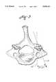
- FIG. 1is a diagrammatic posterior view of the cervical spine
- FIG. 2is a diagrammatic side view of the cervical spine illustrating the cranial-ward orientation of the desired bone screw locations
- FIG. 3is a superior sectional diagrammatic view illustrating the lateral orientation of the bone screw locations
- FIG. 4is a perspective view illustrating the location of the bone screws in accordance with this invention.
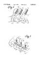
- FIG. 5is a perspective view illustrating the assembly of a rod on a lower saddle in accordance with the present invention.
- FIG. 6is a view similar to FIG. 5 illustrating the completed assembly in accordance with one embodiment of the present invention.
- FIG. 7is a view similar to FIG. 5 illustrating the completed assembly in accordance with a second embodiment of the present invention.
- FIG. 8is a view similar to FIG. 5 illustrating the completed assembly in accordance with a third embodiment of the present invention.
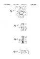
- FIG. 9is a view, in section, of a bone screw taken along the line 9--9 of FIG. 10;
- FIG. 10is a side view of a bone screw in accordance with the present invention.
- FIG. 11is a plan view of the bottom surface of the lower left hand saddle
- FIG. 12is a side view taken along the line 12--12 of FIG. 11;
- FIG. 13is a side view taken along the line 13--13 of FIG. 11;
- FIG. 14is an end view taken along the line 14--14 of FIG. 11;
- FIGS. 15, 16, 17, and 18are views similar to FIGS. 11, 12, 13 and 14 but illustrating a lower right hand saddle
- FIG. 19is a plan view of the top surface of an upper left hand saddle
- FIG. 20is a side view taken along line 20--20 of FIG. 19;
- FIG. 21is a side view taken along line 21--21 of FIG. 19;
- FIG. 22is a side view taken along line 22--22 of FIG. 19, showing the front face
- FIGS. 23, 24, and 25are views similar to FIGS. 20, 21 and 22 but illustrating an upper right hand saddle on which a lock washer is secured;
- FIG. 26is a perspective view, as seen from the front face, on the same side as the rod receiving aperture, illustrating the mating fit of the upper and lower left saddles;
- FIG. 27is a plan view of a cervical screw spacer in accordance with the present invention.
- FIG. 28is a side view of the spacer taken along line 28--28 of FIG. 27;
- FIGS. 29, 30, 31, and 32are views similar to FIGS. 11, 12, 13, and 14 but illustrating a lower left hand saddle with an integral spacer in accordance with the present invention
- FIG. 33is a side view of another embodiment of an upper saddle for use in the present invention.
- FIG. 34is a sleeve nut for use in clamping the upper saddle illustrated in FIG. 33 to the bone screw;
- FIG. 35is a perspective view illustrating an occipital plate assembly attached to the occipital squama, on either side of the external occipital crest;
- FIG. 36is a plan view of a lower occipital plate
- FIG. 37is a side view taken along line 38--38 of FIG. 36 of the plate of FIG. 36 without an occipital plate stud assembled into the lower occipital plate;
- FIG. 38is a side view taken along line 38--38 of FIG. 36 of the plate of FIG. 36 with an occipital plate stud assembled into the lower occipital plate;
- FIG. 39is a side view taken along line 39--39 of FIG. 36 of the plate of FIG. 36 with an occipital plate stud assembled into the lower occipital plate;
- FIG. 40is a plan view of the under side of an upper occipital plate
- FIG. 41is a side view of an upper and lower occipital plate assembled together, taken along a line similar to that of 39--39 in FIG. 36;
- FIG. 42is a plan view of an occipital plate stud
- FIG. 43is a side view taken along line 43--43 of FIG. 42;
- FIG. 44is a top plan view of another embodiment of an occipital plate which is shown partially assembled
- FIG. 45is an exploded side view of the embodiment of FIG. 44;
- FIG. 46is a perspective view illustrating an occipital plate assembly attached to the occipital crest with a cross-brace over C1;
- FIG. 47is a perspective view of a cross-brace.
- the system of the present inventionrelates to a fixation system which comprises bone screws, saddles, rods, clamps and nuts, all uniquely structured for use in the cervical spine region. Fracture dislocations and dislocations of the cervical spine are indications in which the system of the present invention are likely to be of most benefit.
- the screw and rod system of the present inventionwould prevent virtually all motion in the spinal segments instrumented. Two or more segments may be instrumented and stabilized, if desired. If a patient has a severe fracture of the lateral mass of a cervical vertebra, a broken segment may be skipped, and three segments fused together. Cross-bracing may be used over the skipped segment to prevent rotation in cases of excessive instability. If there are multiple laminar fractures, the system of the present invention may be used since there is no limit to the number of levels which can be stabilized. Attachment to the occipital bone at the skull may also be done safely and efficiently.
- the system of the present inventionmay be assembled posteriorly first, thus providing immediate fixation. The surgeon may then proceed anteriorly, removing disc material and grafting bone as necessary. In degenerative cervical disease, often dramatic posterior decompression is necessary in order to decompress the nerves adequately.
- the system of the present inventionmay be used to stabilize the spine after these procedures. In laminoplasty much of the external fixation with casts or braces can be eliminated by use of the fixation system of the present invention. Usually a light neck brace or soft collar is sufficient.
- system of the present inventionmay be used in the repair of a swan neck deformity. This deformity results from extensive posterior decompression.
- the system of the present inventionalthough intended for use primarily in the cervical spine, may be extended into the upper thoracic spine.
- the screwsmay be placed in the uppermost vertebrae of the thoracic spine and also in the cervical spine, even though there is a rather marked curvature in this area.
- the rodscan be contoured to fit the locations of the screws and saddles in any position or location.
- FIG. 1illustrates the cervical spine from C1 to C7. Labelled in the drawing are the lateral mass 40, the superior facet 42, the inferior facet 44 and the lamina 46.
- FIG. 2illustrates the angle between the outer surface 48 of the lateral mass and the transverse left to right axis of the cervical spine, as indicated by the dotted line 50. It is apparent that there is greater bone mass at a cranial-ward angle than along the transverse axis 50.
- the bone screwsdescribed in detail below, are installed in the lateral mass at a cranial-ward angle of between 20° and 30°, the angle between the transverse axis 50 and line 52.
- the bone screwsare also angled lateral-ward between 10° and 20° as indicated in FIG. 3, the angle between dotted line 54 (representing the transverse axis front to back) and solid line 56.
- FIGS. 4 to 8illustrate the orientation and general sequence of installing the fixation system of the present invention.
- bone screws 90described in detail below, are placed in the lateral mass, angled as described above.
- a spacer 270described in detail below, has also been installed to raise the bone screws to a desired elevation above the plane of the bone.
- Bone screwsare inserted on each side of the cervical spine.
- a lower saddle 110a lower left hand saddle
- 150a lower right hand saddle
- a rod 58is placed in the lower saddle.
- a mastering procedure described in U.S. Pat. No. 4,653,481may be used to configure the rod curvature.
- the next stepinvolves assembling an upper saddle 190 (an upper left hand saddle) or 230 (an upper right hand saddle) over the bone screw and rod, as shown in FIGS. 6 to 8.
- the entire assemblyis held together by a locking assembly 60 which operates to bolt the upper and lower saddles onto the rod and to secure the saddles to the bone screw.
- the bone screw 90is illustrated.
- the bone screw and other components of the present inventionare preferably made of 316 LVM steel, although any other appropriate material for surgical implantation, of equivalent strength, may be used.
- the bone screwincludes a longitudinal axis and a first threaded end 92 for screwing into the cervical vertebra. Adjacent to the first threaded end is a flange section 94 and a clamp receiving section 96 is adjacent to the flange. Located on an end remote from the threaded end 90 is a second threaded end 98.
- the portion of the bone screw from the flange 94 to the end of the threaded end 98is generally of a fixed dimension to accommodate the half-saddles and locking mechanism. Typically this dimension is approximately 10 mm in length, with a diameter of about 3.5 mm.
- the length of the bone screw from the flange to the free end of the first threaded section 90may vary from about 10 to 19 mm with a major thread diameter of about 3.5 mm and a minor thread diameter of about 2.5 mm.
- the flange diameteris about 5.3 mm and thus extends radially beyond the outer diameter of the threaded end 92.
- a portion 100 of the flange facing the first threaded section 90is tapered, as shown.
- the flangeis oriented in a plane which is perpendicular to the long axis of the bone screw.
- Located between the flange and the threaded end 98is a non-threaded cylindrical section 102 which has a diameter greater than the diameter of the threaded section 98 but smaller than the diameter of the flange.
- the cylindrical sectionacts as a clamp receiving section for the upper and lower half saddles.
- the clamp receiving sectionincludes spaced exterior flat sections 104 and 106 which mate with internal flat sections on the lower saddle. These flat sections also permit the use of an appropriate tool to thread the bone screw into the lateral mass of the vertebrae.
- FIGS. 11 to 14illustrate a lower left hand saddle 110 which includes an unthreaded aperture 112.
- the aperturehas internal flat sections 114 and 116 which mate with the flat sections 104 and 106 on the bone screw preventing rotation of the lower saddle relative to the bone screw when the fixation system is assembled.
- the lower saddleincludes side faces 118 and 120, which are generally flat, a curved rear face 122, a front face 124 and top and bottom faces 126 and 128, respectively.
- a groove, or rod receiving half aperture, 130 on which a rod is receivedis Located in the top face 126 and between the aperture 112 and the front face 124 is a groove, or rod receiving half aperture, 130 on which a rod is received.
- the grooveis preferably serrated, as indicated at 132, the serrations extending axially from one side face to the other to mate with serrations on the rod, which is described in detail below.
- the bottom face 128 of the lower saddleis generally flat and abuts the flange 94 of the bone screw when assembled on the bone screw, i.e., this face is oriented in a plane which is perpendicular to the long axis of the bone screw.
- the top face 126 of the lower left saddleis oriented in a plane which is at an angle to the bottom face 128.
- the axial dimension of side face 118of about 2.1 mm, is less than the axial dimension of side face 120, of about 4.8 mm, as measured along the long axis of the bone screw, the rear face forming a gradual transition section whose axial dimension progresses from that of side face 118 to that of side face 120.
- the axial dimension from the bottom of the groove 130 to the bottom face along side face 118is less than the axial dimension from the bottom of the groove 130 to the bottom face along side face 120.
- a portion 134 of the bottom face 128includes a taper which is narrow at the end adjacent to side face 118 and broader adjacent to side face 120 and forms a transition section from the top face to the front face 124.
- the front face 124is a relatively narrow section, see FIG. 14, which is angularly oriented, represented by angle "a,” in the same plane as the top face.
- the angle "a"is between about 10° to 25°, with 12° or 22° being preferred.
- FIGS. 15 to 18a lower right hand saddle 150 is illustrated.
- the lower right hand saddleis basically the same as the lower left hand saddle already described, except that the angular orientation is reversed.
- face 118has a greater axial length than face 120, while the top face 126, as illustrated in FIG. 18, is oriented in an opposite angular orientation as compared to face 126 of FIG. 14. Therefore, left hand half-saddles are used for installation on the left hand side of the vertebrae and right hand half-saddles are installed on the right hand side of the vertebrae, thus allowing a common angular displacement, cranial-ward, of the fixation device.
- FIGS. 19 to 22A upper left hand saddle 190, of one embodiment of the present invention, is illustrated in FIGS. 19 to 22.
- the upper saddleincludes a bottom face 192 adapted to be positioned in facing relation with the top face 126 of the lower saddle, side faces 194 and 196, a curved rear face 198 and a front face 200 and a top face 202.
- the upper saddleincludes an unthreaded generally circular aperture 204 which aligns with the aperture of the lower saddle and when the assembly is place over the end 98 of the bone screw. There are no interior flats in aperture 204.
- a groove, or rod receiving half aperture, 206Located in the bottom face 192 and between the aperture 204 and the front face 200 is a groove, or rod receiving half aperture, 206 on which a rod is received for clamping.
- the groove 206is preferably serrated, as indicated at 208, the serrations extending axially from one side face to the other to mate with serrations on the rods when the fixation device is assembled together.
- the top face 202 of the upper saddleis generally flat and is oriented in a plane which is perpendicular to the long axis of the bone screw and generally parallel to the lower or bottom face 128 of the lower saddle.
- the bottom face 192 of the upper left saddleis oriented in a plane angularly disposed with respect to the top face 202, but in an angular orientation for a mating fit with the face 126 of the lower saddle.
- the axial dimension of side face 196is less than the axial dimension of side face 194, of about 4.8 mm, as measured along the long axis of the bone screw, the rear face 198 again forming a gradual transition section whose axial dimension progresses from that of side face 196 to that of side face 194. Accordingly, the axial dimension from the bottom of the groove 206 to the top face along side face 196 is less than the axial dimension from the bottom of the groove 206 to the top face along side face 194.
- a portion 210 of the top face 202includes a taper which is narrow at the end adjacent side face 196 and broader adjacent side face 194 and forms a transition section from the bottom face 192 to the front face 200.
- the front face 200is a relatively narrow section, see FIG. 22, which is angularly oriented in the same plane as the top face at an angle "a". Angle "a" is between about 10° to 25°, with 12° or 22° being preferred.
- the rodsmade of the material already described, are about 3.1 mm in diameter and may vary in length from about 25 mm to at least about 100 mm as required for the fixation procedure being performed.
- the outer surface of the rodis serrated along its length, having for example 28 teeth and the serrations match those on the grooves of the saddles.
- a locking assembly 60comprises a locking washer wherein a locking tang 220 of a lock washer is received in this aperture 212.
- the lock washer 214is a separate item assembled between the upper saddle 230 and a nut 260, see FIG. 7.
- the upper right hand saddleis basically the same as the upper left hand saddle already described, except that the angular orientation is reversed. In these figures, the same numbers are used to describe similar parts as described in FIGS. 19 to 22.
- the lock washer 214includes three tangs, 216 and 218 which are deformed upwardly, and 220 which is deformed downwardly and received in the blind aperture 212. Tang 220 effectively attaches the lock washer 214 to the upper saddle. When tangs 216 and 218 are deformed upwardly they lock the nut in place and prevent it from loosening after installation.
- the assemblyis essentially completed.
- the tangs 216 and 218are deformed around a nut 260 threaded on the end 98 of the bone screw.
- the lower saddleincludes interior flats 116 and 114 which mate with flats 106 and 104 on the bone screw, the lower saddle is prevented from rotating relative to the bone screw.
- the upper saddleis prevented from rotating relative to the lower saddle due to the inclined mating faces 126 and 192.
- the saddleswhich form a rod clamp are bolted against the shoulder 94 of the bone screw, as contrasted to being bolted against the bone of the cervical spine, there is substantial strength in the completed assembly. Further, the rod(s) are firmly secured in the clamp formed by the mating saddle assemblies which form a rod receiving aperture since the grooves, or rod receiving half apertures, and the rod are dimensioned for good purchase and serrated to prevent rod rotation relative to the clamp. The above is true of both the right and left hand configurations.
- the lock nut illustrated FIG. 7is a hexagonal nut, but other nuts may be used.
- the locking nutis an acorn nut with a smooth, curved top surface to reduce possible irritation to the muscles which cover the fixation device when it is installed in a patient.
- FIGS. 27 and 28One way of achieving this is by the use of a cervical spacer 270 illustrated in FIGS. 27 and 28.
- the assembled location of the spaceris shown in FIG. 4, between the tapered under surface of the screw flange 94 and the cervical bone structure.
- This spacermade of material already described, is generally cylindrical in shape and includes an aperture 272 through which the bone screw passes.
- a counterbored section 274mates with the curved under surface 100 of the bone screw flange.
- Angularly oriented face 276normally rests against the bone, the angle "b" being between 15° and 35°.
- the spacerprovides support for the portion of the bone screw which extends above the bone and provides clearance, where desired.
- FIGS. 29 to 32illustrate a lower left hand saddle assembly 290, which in all essential respects is the same as the lower left hand saddle of FIGS. 11 to 14, save for the presence of an integral spacer extension 292.
- the spacer 292is located on the bottom face 128 and includes a top surface 294 which is essentially flat and planar and oriented in a plane which is perpendicular to the long axis of the bone screw. In installation, the top surface bears against the flange 94 of the bone screw, thus raising the groove 130 a distance corresponding to the vertical height 296 of the extension.
- the vertical height 296may be varied as needed. It is understood that a lower right hand saddle having an integral spacer (not shown) could also be used.
- all parts thus far describedare processed to break all sharp edges and are electropolished and passivated.
- the parts describedmay be sterilized prior to use by any of the known sterilization procedures.
- the screwsare located in the proper position, as determined by the surgeon.
- the spacermay be placed on the bone with the bone screw passing through the spacer.
- the lower saddleis assembled over the bone screw.
- Several screws and saddle assembliesmay be installed. If the rod is to be configured, the mastering technique referred to above may be used.
- the properly configured final rodis then placed in the groove(s) and the upper saddle assembly is placed over the lower saddle and secured in place by any of the several devices already described.
- the cervical fixation deviceis designed to minimize or reduce irritation to the neck muscles which overlay the system once it has been installed.
- the locking nutextends beyond the clamping assembly.
- the length of the screw-clamp assemblytends to cause muscle irritation after implantation.
- a sleeve nutfits into a recess on the upper surface of an upper half-clamp.
- the novel sleeve nut in this embodiment of the present inventiongreatly reduces the overall axial length of the screw-clamp assembly, resulting in a low profile and smooth upper surface of the fixation system which reduces the likelihood for the system's causing the formation of a painful bursa.
- the upper and lower saddle and bone screware similar to those described above and will only be described briefly here to point out the differences. The same numbers are used for parts that are unchanged from the parts described previously.
- the lower saddlesare essentially the same as described above and illustrated in FIGS. 11 to 18.
- An upper saddle 330 illustrated in FIG. 33is provided with an aperture 204 for receipt on the upper threaded end 98 of the bone screw 90.
- the axial length of the upper-half clampis greater than that of the upper threaded end 98 of the bone screw so that, when assembled, none of the threaded portion extends beyond the upper saddle 330.
- the internal diameter of the upper saddle apertureis stepped.
- a lower section 332has a diameter such that, when placed on the bone screw, the upper saddle will fit securely against the cylindrical section 102 of the bone screw.
- An intermediate section 334which abuts the lower section, has an intermediate diameter which is greater than the diameter of the lower section.
- Adjacent the intermediate sectionis an upper section 336, which has a diameter larger than that of the intermediate section.
- the intermediate and upper sectionsare separated by a chamfer line 338. When assembled, the intermediate and upper sections accommodate a sleeve nut 340, illustrated in FIG. 34 which is described in detail below.
- the upper saddlealso includes an arm 342 in which is a groove 130, laterally of the aperture 204.
- the grooveis serrated along its length, as indicated at 132, for mating and gripping the serrated rod.
- the geometry of the upper saddleis the same as described for the upper half saddles described above and places the groove at an inclined orientation which is essentially parallel to the angular orientation of the top face of the lower saddle, i.e., the plane of the groove is angularly oriented with respect to the long axis of the bone screw.
- the serrated surfaces of the upper and lower saddlesare in facing relation to each other and mate with, and firmly grip, the serrated rod.
- the lower and upper saddlesare placed on the bone screw, as described above.
- a sleeve nutis used to hold the lower and upper saddles in place on the bone screw flange 94 and to ensure a firm grip on the rod.
- the sleeve nutis illustrated in FIG. 34.
- the sleeve nut 340has an aperture 344, which is threaded so that it mates with the threaded portion 98 of the bone screw.
- the exterior of the sleeve nutis of different diameters.
- the diameter of the sleeve nut 346is at its smallest and is sized such that the sleeve nut will fit into the stepped region 334 of the upper saddle.
- a large-diameter portion of the sleeve nut 348is located at the juncture of the small- and large-diameter portion of the sleeve nut.
- the large-diameter portionis sized so that it will fit into the stepped region 336 of the upper saddle, thus holding the upper saddle and the lower saddle securely in place when the sleeve nut is screwed onto the bone screw.
- the stepped interior of the upper saddleallows a distribution of the force conferred by the sleeve nut on the upper saddle over a larger area.
- a chamfer line 352is locate at the bottom of the sleeve nut.
- the top face 354 of the sleeve nutincludes four radial notches 356, placed at equal distances from each other. The notches align with prongs of a driver, not shown, so that the surgeon can more easily attach the sleeve nut to the bone screw.
- the lower saddleis assembled over an bone screw, and then, after the rod is in position, the upper half-clamp is installed.
- the sleeve nutis then threaded on the upper threaded-end portion of the bone screw and tightened down, using a driver.
- the prongs of the driverare mated with the notches of the sleeve nut and the driver is then used to tighten the sleeve nut into the upper saddle.
- the sleeve nutwhen tightened down, is completely contained within the aperture 204, leaving exposed a small portion of the upper edge of the face 358 of the upper saddle.
- the exposed portion of the face 358is crimped at one point along its periphery corresponding to one of the radial notches. The crimp ensures that the sleeve nut is firmly locked in place and that undesired rotation of the sleeve nut is inhibited.
- the crimpis easily overcome by using the driver to remove the sleeve nut, and the sleeve nut is unscrewed to release the upper and lower saddles. After any required adjustment has been made, the screw-and-clamp assembly is secured in place, as described above.
- the advantage of the low profile cervical fixation system of the present inventionis, that the axial length (height) of the screw-clamp assembly is greatly reduced, when compared to the height of other screw-clamp assemblies, since the axial length of previous screws had to be of a dimension sufficient to accommodate at least one nut and locking washer above the clamp.
- the height of the screw-clamp assembly as installedincreased the probability of muscle irritation by the clamp assembly.
- the installed fixation systemhas a top surface which is in a single plane which reduces muscle irritation.
- the sleeve nutfits into a recess on the upper surface of the upper saddle, greatly reducing the overall axial height of the bone screw above the upper saddle. This low profile of the fixation system reduces the likelihood of the system's causing the formation of a painful bursa.
- the cervical fixation systemis used to treat damage to the spine in the region of the first (atlas) or second (axis) cervical vertebra.
- the fixation deviceis attached at one end to the cervical vertebra, as described above.
- the other endis attached to the occipital squama, on either side of the external occipital crest, by an occipital plate assembly 350, as shown in FIG. 35.
- the occipital plate assemblycomprises a lower occipital plate 360 (illustrated in FIGS. 36 to 39 and 41), an upper occipital plate 400 (illustrated in FIGS. 40 and 41), an occipital plate stud 420 (illustrated in FIGS.
- a serrated rod 356connects the occipital plate assembly to the cervical assembly 358.
- FIGS. 36 to 39illustrate a lower occipital plate 360.
- the lower occipital plateis a generally rectangular shaped plate 362 with an outwardly extending arm 364 perpendicular to the rectangular shaped plate, and located at the middle of one of the long sides of the rectangle.
- the armincludes a groove 366 (see FIG. 39).
- the grooveis serrated along its length, as indicated at 368, for mating and griping the serrated rod 356.
- apertures 370for receiving screws 354 and for attaching the occipital plate to the occipital squama.
- Each aperturehas a greater diameter 371 at an upper side of the plate that the diameter 373 at a lower side of the plate. The different diameters of the aperture allow the "V" shaped head of the screw to seat into the aperture and to hold the lower occipital plate onto the occipital squama.
- a generally cylindrical third aperture 372Located between the apertures 370, adjacent to the arm, is a generally cylindrical third aperture 372 (see FIG. 37).
- One sidewall 374 of the aperture 372is flattened (see FIG. 36).
- the apertureis counterbored 376.
- the counterbored aperture 372acts to seat a threaded occipital plate stud 420.
- the studhas a flat section 430 on one side for mating with the flattened sidewall of aperture 372. The flat sides act to correctly locate the stud in aperture 372 and to prevent it rotating relative to the lower occipital plate.
- channels 378Located on the under side of the lower occipital plate are channels 378.
- the channelsallow the lower occipital plate to flex so that it can be molded to the gentle curve of the occipital squama and thus lay flat against and conform to the occipital squama surface.
- Stud 420illustrated in FIGS. 42 and 43, comprises a threaded end 422 which is adjacent to a non-threaded section of similar diameter 424.
- the non-threaded sectionabuts a shoulder 426 which separates the non-threaded section 426 from a larger diameter second non-threaded section 428.
- the diameter of the non-threaded section 428is dimensioned so that it will fit "snugly" into aperture 370 when the plate stud is assembled into the lower occipital plate.
- Non-threaded section 428includes the flat section 430, described above.
- a second shoulder 432Adjacent to non-threaded section 428 is a second shoulder 432 which has an increasing tapered diameter greater than that of the non-threaded section 428 as it extends away from that section.
- Shoulder 432is of a larger diameter than the diameter of the aperture 372.
- the counterbored section of the aperture 372acts to seat the shoulder 432.
- the larger diameter of shoulder 432prevents the stud from slipping through the aperture 372 when the stud and lower occipital plate are assembled (see FIG. 38).
- the upper occipital plate 400illustrated in FIGS. 40 and 41, is a rectangular shaped plate with an aperture 402 at one end of the plate.
- the diameter of aperture 420is dimensioned so that it will fit "snugly" onto non-threaded section 424 when the upper occipital plate is assembled onto the plate stud.
- the occipital plate studis slipped into the aperture 372 in the lower occipital plate so that it extends up away from the occipital squama by aligning flat sections 430 and 374.
- the lower occipital plateis then attached to the occipital squama using screws 354.
- the upper plateis placed onto the stud and aligned to bring the grooves 368 and 404 in facing relation to form a rod receiving aperture. A rod is placed into the rod receiving aperture and the upper plate is tightened to the lower plate.
- the upper plateis clamped to the lower plate by screwing an acorn nut 352 onto the threaded end of the stud.
- the acorn nutis locked into place with a lock washer 353 which includes three deformable tangs 355 (only two of which are shown in FIG. 35). Two of the tangs are deformed upwardly, and one is deformed downwardly and received in the blind aperture 406 (illustrated in FIG. 41).
- the downwardly deformed tangeffectively attaches the lock washer to the upper plate.
- the upwardly deformed tangslock the nut in place and prevent it from loosening after installation.
- Such a nut and lock washerare described above in relation to FIGS. 22 and 24 to 26, and are identical to the nut and lock washer for attachment of the upper plate.
- the locking assemblycomprises a low profile system which includes a locking nut which fits into a recess on the upper surface of the upper plate.
- a low profile systemis described in conjunction with FIGS. 33 and 34, and a similar system can be used for attachment of the upper plate.
- the upper plateis modified to include the stepped sections (as illustrated in FIG. 33) into the upper surface of the upper occipital plate, around aperture 402. The upper plate is then attached to the plate stud with a nut similar to that illustrated in FIG. 34.
- the occipital plate assemblyis designed for attachment to the occipital crest.
- the occipital plate assembly 440comprises an occipital plate 442, rod clamps 444, occipital plate studs 446 (similar to element 420 described above), nuts 448 for attaching the clamp to the occipital plate stud, and screws 450 for attaching the occipital plate to the occipital crest.
- a serrated rod 356connects the occipital plate assembly to cervical clamp assemblies 358 (see FIG. 46). This assembly has the advantage of being attached to the occipital crest which has thicker bone than other parts of the skull.
- FIGS. 44 and 45illustrate an occipital plate assembly 440.
- a lower occipital plateis a generally "T" shaped flat plate 442. Located at either end of the cross-bar of the "T" are upwardly facing grooves 452. The grooves are serrated along their length, as indicated at 454, for mating and griping the serrated rods 356 (see FIG. 46). Adjacent to the grooves are apertures 458 which are generally cylindrical. One sidewall 460 of the aperture 458 is flattened (see FIG. 44). On an under surface of the plate the aperture is counterbored 462 (see FIG. 45). The counterbored aperture acts to seat a threaded occipital plate stud 446 (see FIG. 45).
- the stud 446is the same as stud 420, illustrated in FIGS. 42 and 43, and the same reference numerals are used for the same parts.
- the studhas a flat section 430 on one side for mating with the flattened sidewall of the aperture. The flat sides act to correctly locate the stud in the aperture and to prevent it from rotating relative to the lower occipital plate once installed.
- apertures 510for receiving screws 450 (see FIG. 46) and for attaching the occipital plate to the occipital crest.
- Each aperturehas a greater diameter 512 at an upper side of the plate than the diameter 514 at a lower side of the plate. The different diameters of the aperture allow the head of the screw to seat into the aperture and to hold the lower occipital plate onto the occipital crest.
- channels 464Located on the under side of the lower occipital plate are channels 464.
- the channelsallow the occipital plate to flex so that it can be molded to the gentle curve of the occipital region of the skull and thus lay flat against and conform to the skull surface.
- the clamps or upper occipital plates 444are similar to clamps 400 illustrated in FIGS. 40 and 41.
- the same reference numeralsare used for similar parts.
- the clampsare rectangular shaped with an aperture 402 adjacent to a groove 404.
- the grooveincludes serrations which are shown at 470.
- the aperture 402includes stepped sections 466 and 468.
- the lower section 468 of the apertureis dimensioned so that it will fit the lower section 346 of a sleeve nut such as 448 (which is the same as sleeve nut 340 described in FIG. 34 above and the same reference numerals are used for the same parts).
- the upper section 466is dimensioned to accommodate the upper section of sleeve nut 448.
- the internal aperture 344 of the sleeve nutis threaded and dimensioned to fit onto stud 446.
- groove 452aligns with the groove 404 of the clamp to form a rod receiving aperture for securely gripping the serrated rod 356.
- occipital plate studsare slipped into apertures 458 in the occipital plate so that they extend up and away from the lower surface of the occipital plate.
- the flat sections of the aperture and the studare aligned to prevent rotation of the studs relative to the occipital plate.
- the occipital plateis then attached to the skull using screws 450.
- clamps 444are placed onto the stud and aligned to bring the grooves 404 and 452 in facing relation to form rod receiving apertures. Rods are placed into the rod receiving apertures and the clamps are tightened to the occipital plate by tightening sleeve nuts 448 onto studs 446.
- an exposed portion of the clampis crimped as described above.
- the crimpensures that the sleeve nuts are firmly locked in place and that undesired rotation of the sleeve nuts is inhibited.
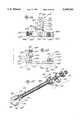
- FIG. 47illustrates a cross-brace 480.
- the cross-bracecomprises a threaded rod 482. Attached to a first end of the threaded rod is a fixed clamp 484. At a second end of the threaded rod is an adjustable clamp 486.
- the fixed clampcomprises two half clamps, 488 and 490, lock washer 492 (which is similar to lock washers 353 and 214 illustrated in FIGS. 35 and 26, respectively) and nut 494 (which is similar to nut 260 illustrated in FIG. 26).
- the half-clamps 488 and 490each include an aperture 496 for threading onto the threaded rod and a groove 498 adjacent to the aperture.
- the adjustable clampcomprises two half clamps, 500 and 502 (which are similar to half-clamp 490), two lock washers 492 and two nuts 494.
- the half-clamps 500 and 502also each include an aperture 496 for threading onto the threaded rod and a groove 498 adjacent to the aperture.
- lock washer 492 and half-clamp 490are threaded, in order, onto a first end of the threaded rod.
- the half-clamp 490is oriented such that the groove is facing toward the first end of the threaded rod.
- Half-clamp 488is then attached to the end of the threaded rod by electron beam welding or other suitable means of attachment.
- the half-clamp 488is oriented such that the groove is facing away from the first end of the threaded rod and toward the groove of half-clamp 490 such that the grooves can align to form a rod receiving aperture.
- Nut 494, lock washer 492, half-clamp 500, half-clamp 502, a second lock washer 492 and a second nut 494are threaded, in order, onto the second end of the threaded rod.
- the half-clamp 500is oriented such that the groove is facing toward the second end of the threaded rod.
- the half-clamp 502is oriented such that the groove is facing away from the second end of the threaded rod and toward the groove of half-clamp 502 such that the grooves can align to form a rod receiving aperture.
- the rod receiving aperture of clamp 484is placed over a serrated rod on one side of the vertebrae (see FIG. 46) and nut 496 is tightened to clamp half-clamp 490 onto the rod and against half-clamp 488 thus securing the clamp to the rod. Tangs of the lock washer are then bent into a hole on the surface of the half-clamp 490 (not shown) and up around the nut, as described above, to prevent nut 494 from rotating and coming loose after installation.
- the groove of half-clamp 500is placed against a serrated rod on the side of the vertebrae opposite that of clamp 484 (see FIG. 46) and one nut 494 is tightened to clamp half-clamp 490 onto the rod.
- the groove of half-clamp 502is placed against on the other side of the serrated rod, opposite half-clamp 500 and the second nut 494 is tightened to clamp half-clamp 502 onto the rod, thus securing the clamp to the rod. Tangs of the lock washers are then bent into a hole on the surface of the half-clamp 500 and 502 (not shown) and up around the nut, as described above, to prevent nut 494 from rotating and coming loose after installation.
- This cross-braceallows for adjustable installation to cross-brace rods which are at different distances, but, since one of the half-clamps is fixed on the rod, the amount of manual manipulation required to achieve the required adjustment is minimized.
Landscapes
- Health & Medical Sciences (AREA)
- Orthopedic Medicine & Surgery (AREA)
- Life Sciences & Earth Sciences (AREA)
- Neurology (AREA)
- Surgery (AREA)
- Heart & Thoracic Surgery (AREA)
- Engineering & Computer Science (AREA)
- Biomedical Technology (AREA)
- Nuclear Medicine, Radiotherapy & Molecular Imaging (AREA)
- Medical Informatics (AREA)
- Molecular Biology (AREA)
- Animal Behavior & Ethology (AREA)
- General Health & Medical Sciences (AREA)
- Public Health (AREA)
- Veterinary Medicine (AREA)
- Neurosurgery (AREA)
- Surgical Instruments (AREA)
Abstract
Description
Claims (4)
Priority Applications (3)
| Application Number | Priority Date | Filing Date | Title |
|---|---|---|---|
| US08/241,768US5545164A (en) | 1992-12-28 | 1994-05-12 | Occipital clamp assembly for cervical spine rod fixation |
| PCT/US1995/005942WO1995031147A1 (en) | 1994-05-12 | 1995-05-11 | Cervical spine rod fixation system |
| AU25484/95AAU2548495A (en) | 1994-05-12 | 1995-05-11 | Cervical spine rod fixation system |
Applications Claiming Priority (2)
| Application Number | Priority Date | Filing Date | Title |
|---|---|---|---|
| US99811692A | 1992-12-28 | 1992-12-28 | |
| US08/241,768US5545164A (en) | 1992-12-28 | 1994-05-12 | Occipital clamp assembly for cervical spine rod fixation |
Related Parent Applications (1)
| Application Number | Title | Priority Date | Filing Date |
|---|---|---|---|
| US99811692AContinuation-In-Part | 1992-12-28 | 1992-12-28 |
Publications (1)
| Publication Number | Publication Date |
|---|---|
| US5545164Atrue US5545164A (en) | 1996-08-13 |
Family
ID=22912101
Family Applications (1)
| Application Number | Title | Priority Date | Filing Date |
|---|---|---|---|
| US08/241,768Expired - LifetimeUS5545164A (en) | 1992-12-28 | 1994-05-12 | Occipital clamp assembly for cervical spine rod fixation |
Country Status (3)
| Country | Link |
|---|---|
| US (1) | US5545164A (en) |
| AU (1) | AU2548495A (en) |
| WO (1) | WO1995031147A1 (en) |
Cited By (170)
| Publication number | Priority date | Publication date | Assignee | Title |
|---|---|---|---|---|
| US5876457A (en)* | 1997-05-20 | 1999-03-02 | George J. Picha | Spinal implant |
| US5947968A (en)* | 1997-11-03 | 1999-09-07 | Rogozinski; Chaim | Graft anchor and method |
| FR2786684A1 (en)* | 1998-12-02 | 2000-06-09 | Fixano | Vertebral arthrodesis frame has pair of rods which can be bent to form required length |
| US6110173A (en)* | 1998-09-15 | 2000-08-29 | Advanced Spine Fixation Systems, Inc. | Transverse connector for spinal fixation systems |
| US6146382A (en)* | 1998-09-23 | 2000-11-14 | Spinal Concepts, Inc. | Occipito-cervical stabilization system and method |
| WO2000067651A1 (en)* | 1999-05-10 | 2000-11-16 | Highgate Orthopedics, Inc. | Systems and methods for spinal fixation |
| WO2001091656A3 (en)* | 2000-06-01 | 2002-05-30 | Hipokrat Tibbi Malzemeler Imal | Spinal system |
| US20020082598A1 (en)* | 2000-06-23 | 2002-06-27 | Teitelbaum George P. | Percutaneous vertebral fusion system |
| US6478798B1 (en) | 2001-05-17 | 2002-11-12 | Robert S. Howland | Spinal fixation apparatus and methods for use |
| US6485491B1 (en) | 2000-09-15 | 2002-11-26 | Sdgi Holdings, Inc. | Posterior fixation system |
| US6524315B1 (en) | 2000-08-08 | 2003-02-25 | Depuy Acromed, Inc. | Orthopaedic rod/plate locking mechanism |
| US20030060827A1 (en)* | 2001-09-26 | 2003-03-27 | Coughln Michael John | Plate for fixing the bones of a joint, in particular a metatarso-phalangeal joint |
| WO2003022132A3 (en)* | 2001-09-07 | 2003-07-03 | Spine Works Llc | Halo/collar cervical orthosis |
| US20030153913A1 (en)* | 2002-02-13 | 2003-08-14 | Moti Altarac | Occipital plate and rod system |
| US20040002707A1 (en)* | 2002-06-28 | 2004-01-01 | Chunfeng Zhao | Spinal fixation support device and methods of using |
| US6673073B1 (en)* | 1999-11-29 | 2004-01-06 | Schaefer Bernd | Transverse connector |
| US20040106925A1 (en)* | 2002-11-25 | 2004-06-03 | Culbert Brad S. | Soft tissue anchor and method of using same |
| US20040133207A1 (en)* | 2002-10-11 | 2004-07-08 | Abdou M. Samy | Distraction screw for skeletal surgery and method of use |
| US6770075B2 (en)* | 2001-05-17 | 2004-08-03 | Robert S. Howland | Spinal fixation apparatus with enhanced axial support and methods for use |
| US20040153070A1 (en)* | 2003-02-03 | 2004-08-05 | Barker B. Thomas | Midline occipital vertebral fixation system |
| US20040181222A1 (en)* | 2003-01-16 | 2004-09-16 | Culbert Brad S. | Locking plate for bone anchors |
| US20040210216A1 (en)* | 2003-04-17 | 2004-10-21 | Farris Robert A | Spinal fixation system and method |
| US20050004573A1 (en)* | 2003-04-18 | 2005-01-06 | M. Samy Abdou | Bone fixation system and method of implantation |
| US20050080420A1 (en)* | 2003-08-20 | 2005-04-14 | Farris Robert A. | Multi-axial orthopedic device and system |
| US6902565B2 (en) | 2001-02-21 | 2005-06-07 | Synthes (U.S.A.) | Occipital plate and system for spinal stabilization |
| US20050154339A1 (en)* | 2004-01-13 | 2005-07-14 | Farley Daniel K. | Cervical orthosis |
| US20050177163A1 (en)* | 2003-12-29 | 2005-08-11 | Abdou M. S. | Plating system for bone fixation and method of implantation |
| US20050177160A1 (en)* | 2004-02-10 | 2005-08-11 | Baynham Bret O. | Dynamic cervical plate |
| US20050197660A1 (en)* | 2004-03-08 | 2005-09-08 | Haid Regis W.Jr. | Occipital and cervical stabilization systems and methods |
| US20050273120A1 (en)* | 2004-05-03 | 2005-12-08 | Abdou M S | Devices and methods for the preservation of spinal prosthesis function |
| US20050283153A1 (en)* | 2004-06-17 | 2005-12-22 | Poyner Jeffrey W | Orthopedic fixation system and method of use |
| US20050288669A1 (en)* | 2004-06-14 | 2005-12-29 | Abdou M S | Occipito fixation system and method of use |
| US20060004363A1 (en)* | 2004-05-25 | 2006-01-05 | University Of Utah Research Foundation | Occipitocervical plate |
| US20060074488A1 (en)* | 2004-08-23 | 2006-04-06 | Abdou M S | Bone fixation and fusion device |
| US20060111728A1 (en)* | 2004-10-05 | 2006-05-25 | Abdou M S | Devices and methods for inter-vertebral orthopedic device placement |
| US20060155284A1 (en)* | 2005-01-07 | 2006-07-13 | Depuy Spine Sarl | Occipital plate and guide systems |
| US20060195089A1 (en)* | 2005-02-03 | 2006-08-31 | Lehuec Jean-Charles | Spinal plating and intervertebral support systems and methods |
| US20060217710A1 (en)* | 2005-03-07 | 2006-09-28 | Abdou M S | Occipital fixation system and method of use |
| US20060229611A1 (en)* | 2005-03-30 | 2006-10-12 | Sdgi Holdings, Inc. | Spinal rod connector |
| US20060229610A1 (en)* | 2005-03-21 | 2006-10-12 | Zimmer Spine, Inc. | Variable geometry occipital fixation plate |
| US20060229615A1 (en)* | 2005-02-18 | 2006-10-12 | Abdou M S | Devices and methods for dynamic fixation of skeletal structure |
| US20070016189A1 (en)* | 2005-06-30 | 2007-01-18 | Depuy Spine Sarl | Orthopedic clamping hook assembly |
| US20070093828A1 (en)* | 2005-10-07 | 2007-04-26 | Abdou M S | Devices and methods for inter-vertebral orthopedic device placement |
| US20070106383A1 (en)* | 2005-10-03 | 2007-05-10 | Abdou M S | Devices and methods for inter-vertebral orthopedic device placement |
| US20070118132A1 (en)* | 2002-07-19 | 2007-05-24 | Triage Medical, Inc. | Method and apparatus for spinal fixation |
| US20070118121A1 (en)* | 2005-10-07 | 2007-05-24 | Alphatec Spine, Inc. | Adjustable occipital plate |
| US20070123872A1 (en)* | 2004-05-25 | 2007-05-31 | University Of Utah Research Foundation | Occipitocervical plate |
| US20070162016A1 (en)* | 2005-10-25 | 2007-07-12 | Matityahu Amir M | Bone fastening assembly and bushing and screw for use therewith |
| US20070173843A1 (en)* | 2005-12-22 | 2007-07-26 | Matityahu Amir M | Drug delivering bone plate and method and targeting device for use therewith |
| US20070233085A1 (en)* | 2005-12-23 | 2007-10-04 | Lutz Biedermann | Flexible stabilization device for dynamic stabilization of bones or vertebrae |
| US20070276371A1 (en)* | 2004-02-10 | 2007-11-29 | Baynham Bret O | Dynamic cervical plate |
| US20070299441A1 (en)* | 2006-06-09 | 2007-12-27 | Zachary M. Hoffman | Adjustable Occipital Plate |
| US7314467B2 (en) | 2002-04-24 | 2008-01-01 | Medical Device Advisory Development Group, Llc. | Multi selective axis spinal fixation system |
| US20080045963A1 (en)* | 2006-08-21 | 2008-02-21 | Abdou M S | Bone screw systems and methods of use |
| US20080051783A1 (en)* | 2006-08-02 | 2008-02-28 | Warsaw Orthopedic Inc. | Occipital plating systems and methods |
| US20080058810A1 (en)* | 2003-01-10 | 2008-03-06 | Abdou M S | Bone screw systems and methods of use |
| US20080125781A1 (en)* | 2006-11-28 | 2008-05-29 | Zimmer Spine, Inc. | Adjustable occipital plate |
| US20080147123A1 (en)* | 2006-12-14 | 2008-06-19 | Seaspine, Inc. | Occipital plate assembly |
| US20080177313A1 (en)* | 2006-12-27 | 2008-07-24 | Lemoine Jeremy J | Modular occipital plate |
| US20080177314A1 (en)* | 2006-12-27 | 2008-07-24 | Jeremy Lemoine | Modular occipital plate |
| US20080234766A1 (en)* | 2007-01-29 | 2008-09-25 | Polaris Biotechnology, Inc. | Craniospinal fusion method and apparatus |
| US20080234742A1 (en)* | 2007-03-08 | 2008-09-25 | Cascarino Jose Ludovico | Head Fixation Device |
| US20080234681A1 (en)* | 2004-02-10 | 2008-09-25 | Baynham Matthew G | Dynamic cervical plate |
| US20080281362A1 (en)* | 2007-05-09 | 2008-11-13 | Jeremy Lemoine | Device and system for cranial support |
| US20080287998A1 (en)* | 2007-05-16 | 2008-11-20 | Doubler Robert L | Polyaxial bone screw |
| US20080306550A1 (en)* | 2007-06-07 | 2008-12-11 | Matityahu Amir M | Spine repair assembly |
| US20090018584A1 (en)* | 2007-01-29 | 2009-01-15 | Polaris Biotechnology, Inc. | Vertebra attachment method and system |
| US20090036894A1 (en)* | 2007-01-29 | 2009-02-05 | Polaris Biotechnology, Inc. | Method of treating a neurological condition through correction and stabilization of the clivo-axial angle |
| WO2009055747A1 (en) | 2007-10-24 | 2009-04-30 | Nuvasive, Inc. | Surgical fixation system and related methods |
| US20090125067A1 (en)* | 2007-11-08 | 2009-05-14 | Depuy Spine, Inc. | In-line occipital plate and method of use |
| US20090177230A1 (en)* | 2008-01-08 | 2009-07-09 | Polaris Biotechnology, Inc. | Osteointegration apparatus |
| US20090187191A1 (en)* | 2003-10-17 | 2009-07-23 | Highgate Orthopedics, Inc | Systems, Devices and Apparatuses for Bony Fixation and Disk Repair and Replacement and Methods Related Thereto |
| US7575600B2 (en) | 2004-09-29 | 2009-08-18 | Kyphon Sarl | Artificial vertebral disk replacement implant with translating articulation contact surface and method |
| US20090270924A1 (en)* | 2005-09-30 | 2009-10-29 | Wing Charles A | Occipitocervical Fixation System |
| US7625381B2 (en) | 1997-02-11 | 2009-12-01 | Warsaw Orthopedic, Inc. | System and method for stabilizing a portion of the spine |
| US7628799B2 (en) | 2005-08-23 | 2009-12-08 | Aesculap Ag & Co. Kg | Rod to rod connector |
| US20090306720A1 (en)* | 2007-05-16 | 2009-12-10 | Doubler Robert L | Polyaxial bone screw |
| US20100016906A1 (en)* | 2008-07-21 | 2010-01-21 | Abdou M Samy | Device and method to access the anterior column of the spine |
| US7651497B2 (en) | 1997-02-11 | 2010-01-26 | Warsaw Orthopedic, Inc. | Segmentable plate with locking element |
| US20100042166A1 (en)* | 2000-07-28 | 2010-02-18 | Kumar Kris G | Spinal fixation system |
| US20100114098A1 (en)* | 2006-07-13 | 2010-05-06 | Highgate Orthopedics, Inc. | Devices and methods for stabilizing a spinal region |
| US20100152575A1 (en)* | 2008-01-08 | 2010-06-17 | Polaris Biotechnology, Inc. | Mathematical Relationship of Strain, Neurological Dysfunction and Abnormal Behavior Resulting from Neurological Dysfunction of the Brainstem |
| US7744632B2 (en) | 2006-12-20 | 2010-06-29 | Aesculap Implant Systems, Inc. | Rod to rod connector |
| US20100179597A1 (en)* | 2007-01-29 | 2010-07-15 | Polaris Biotechnology, Inc. | Craniospinal fusion method and apparatus |
| US20100211100A1 (en)* | 2009-02-19 | 2010-08-19 | Mack Claudia | Apparatus for spinal-column stabilization |
| US20100217393A1 (en)* | 2009-02-20 | 2010-08-26 | Theofilos Charles S | Interbody fusion system with intervertebral implant retention assembly |
| US20100222822A1 (en)* | 2002-08-28 | 2010-09-02 | Warsaw Orthopedic, Inc. | Posterior Fixation System |
| US20100268237A1 (en)* | 1999-05-10 | 2010-10-21 | Highgate Orthopedics, Inc. | Systems, Devices and Apparatuses For Bony Fixation and Disk Repair and Replacement Methods Related Thereto |
| US20100312288A1 (en)* | 2007-05-16 | 2010-12-09 | Hammill Sr John E | Thread-thru polyaxial pedicle screw system |
| US20100324684A1 (en)* | 2003-02-12 | 2010-12-23 | Warsaw Orthopedic, Inc. | Spinal Prosthetic Joints |
| US20100324557A1 (en)* | 2009-06-23 | 2010-12-23 | Aesculap Implant Systems, Inc. | Minimal access occipital plate |
| US20110004250A1 (en)* | 2007-11-29 | 2011-01-06 | Uribe Juan S | Apparatus for Occipital-Cervical Fixation Enabling Supplemental Occipital Bone Fixation |
| US20110009911A1 (en)* | 2008-11-14 | 2011-01-13 | Hammill Sr John E | Locking polyaxial ball and socket fastener |
| US20110040336A1 (en)* | 2009-08-13 | 2011-02-17 | Hammill Sr John E | Thread-thru polyaxial pedicle screw system |
| US7901433B2 (en) | 2006-10-04 | 2011-03-08 | Zimmer Spine, Inc. | Occipito-cervical stabilization system and method |
| US20110060368A1 (en)* | 2008-02-22 | 2011-03-10 | Depuy Spine, Inc. | Method and system for trans-lamina spinal fixation |
| US20110087292A1 (en)* | 2009-10-14 | 2011-04-14 | K2M, Inc. | Occipital fixation assembly, system and method for attaching the same |
| US20110106085A1 (en)* | 2009-10-30 | 2011-05-05 | Warsaw Orthopedic, Inc. | Adjustable occipital vertebral fixation system |
| WO2011057178A1 (en) | 2009-11-06 | 2011-05-12 | Dean Lin | System and method for stabilizing and fixating lumbar vertebrae |
| US20110118784A1 (en)* | 2004-02-10 | 2011-05-19 | Baynham Bret O | Cervical Plate Ratchet Pedicle Screws |
| US7947065B2 (en) | 2008-11-14 | 2011-05-24 | Ortho Innovations, Llc | Locking polyaxial ball and socket fastener |
| US7951173B2 (en) | 2007-05-16 | 2011-05-31 | Ortho Innovations, Llc | Pedicle screw implant system |
| US20110152932A1 (en)* | 2009-12-21 | 2011-06-23 | Industrial Technology Research Institute | Flexible Spine Fixing Structure |
| US20110160771A1 (en)* | 2009-12-31 | 2011-06-30 | Industrial Technology Research Institute | Flexible Spine Fixing Structure |
| US8172855B2 (en) | 2004-11-24 | 2012-05-08 | Abdou M S | Devices and methods for inter-vertebral orthopedic device placement |
| US8303630B2 (en) | 2006-07-27 | 2012-11-06 | Samy Abdou | Devices and methods for the minimally invasive treatment of spinal stenosis |
| WO2012135870A3 (en)* | 2011-04-01 | 2012-11-22 | Stachniak Rebecca Elizabeth | Posterior cervical stabilization system and method |
| US8409208B2 (en) | 2008-10-04 | 2013-04-02 | M. Samy Abdou | Device and method to access the anterior column of the spine |
| US8506567B2 (en) | 2009-02-04 | 2013-08-13 | Lanx, Inc. | Occipital plate fixation system |
| US20130238033A1 (en)* | 2012-03-12 | 2013-09-12 | Michael Black | Occipital plate systems |
| US8696676B2 (en) | 2003-02-27 | 2014-04-15 | Aesculap Ag & Co. Kg | Surgical instrument |
| US8702758B2 (en) | 2009-12-31 | 2014-04-22 | Industrial Technology Research Institute | Flexible spine fixing structure |
| US8715284B2 (en) | 2001-03-30 | 2014-05-06 | Interventional Spine, Inc. | Method and apparatus for bone fixation with secondary compression |
| US8771319B2 (en) | 2012-04-16 | 2014-07-08 | Aesculap Implant Systems, Llc | Rod to rod cross connector |
| US20140249581A1 (en)* | 2011-04-01 | 2014-09-04 | Rebecca Elizabeth Stachniak | Posterior Stabilization Systems and Methods |
| US8828056B2 (en) | 2012-04-16 | 2014-09-09 | Aesculap Implant Systems, Llc | Rod to rod cross connector |
| US20150164498A1 (en)* | 2013-12-11 | 2015-06-18 | Arthrex, Inc. | Suture washer |
| US9060813B1 (en) | 2008-02-29 | 2015-06-23 | Nuvasive, Inc. | Surgical fixation system and related methods |
| US9198695B2 (en) | 2010-08-30 | 2015-12-01 | Zimmer Spine, Inc. | Polyaxial pedicle screw |
| US9387013B1 (en)* | 2011-03-01 | 2016-07-12 | Nuvasive, Inc. | Posterior cervical fixation system |
| US9393127B2 (en) | 1999-05-10 | 2016-07-19 | K2M, Inc. | Systems, devices and apparatuses for bony fixation and disk repair and replacement methods related thereto |
| US9453526B2 (en) | 2013-04-30 | 2016-09-27 | Degen Medical, Inc. | Bottom-loading anchor assembly |
| US9522028B2 (en) | 2013-07-03 | 2016-12-20 | Interventional Spine, Inc. | Method and apparatus for sacroiliac joint fixation |
| US9522070B2 (en) | 2013-03-07 | 2016-12-20 | Interventional Spine, Inc. | Intervertebral implant |
| US9526528B2 (en) | 2013-01-29 | 2016-12-27 | Chester Evan Sutterlin, III | Occipital and bone plate assemblies with mesh portions |
| US9827023B2 (en)* | 2007-01-29 | 2017-11-28 | Life Spine, Inc. | Craniospinal fusion method and apparatus |
| US9839530B2 (en) | 2007-06-26 | 2017-12-12 | DePuy Synthes Products, Inc. | Highly lordosed fusion cage |
| US9867714B1 (en) | 2011-09-23 | 2018-01-16 | Samy Abdou | Spinal fixation devices and methods of use |
| US9883951B2 (en) | 2012-08-30 | 2018-02-06 | Interventional Spine, Inc. | Artificial disc |
| US9895236B2 (en) | 2010-06-24 | 2018-02-20 | DePuy Synthes Products, Inc. | Enhanced cage insertion assembly |
| US9913727B2 (en) | 2015-07-02 | 2018-03-13 | Medos International Sarl | Expandable implant |
| US9931223B2 (en) | 2008-04-05 | 2018-04-03 | DePuy Synthes Products, Inc. | Expandable intervertebral implant |
| US9993349B2 (en) | 2002-06-27 | 2018-06-12 | DePuy Synthes Products, Inc. | Intervertebral disc |
| US10058433B2 (en) | 2012-07-26 | 2018-08-28 | DePuy Synthes Products, Inc. | Expandable implant |
| US10111757B2 (en) | 2012-10-22 | 2018-10-30 | Cogent Spine, LLC | Devices and methods for spinal stabilization and instrumentation |
| US10111695B2 (en) | 2001-03-30 | 2018-10-30 | DePuy Synthes Products, Inc. | Distal bone anchors for bone fixation with secondary compression |
| US10390963B2 (en) | 2006-12-07 | 2019-08-27 | DePuy Synthes Products, Inc. | Intervertebral implant |
| US10398563B2 (en) | 2017-05-08 | 2019-09-03 | Medos International Sarl | Expandable cage |
| US20190298527A1 (en)* | 2016-07-08 | 2019-10-03 | Beijing AK Medical Co., Ltd. | Sacral prosthesis |
| US10433977B2 (en) | 2008-01-17 | 2019-10-08 | DePuy Synthes Products, Inc. | Expandable intervertebral implant and associated method of manufacturing the same |
| US10500062B2 (en) | 2009-12-10 | 2019-12-10 | DePuy Synthes Products, Inc. | Bellows-like expandable interbody fusion cage |
| CN110652351A (en)* | 2019-04-08 | 2020-01-07 | 中国人民解放军南部战区总医院 | Internal fixator for dentata for vertebral artery variation |
| US10537436B2 (en) | 2016-11-01 | 2020-01-21 | DePuy Synthes Products, Inc. | Curved expandable cage |
| US10543107B2 (en) | 2009-12-07 | 2020-01-28 | Samy Abdou | Devices and methods for minimally invasive spinal stabilization and instrumentation |
| US10548740B1 (en) | 2016-10-25 | 2020-02-04 | Samy Abdou | Devices and methods for vertebral bone realignment |
| US10548741B2 (en) | 2010-06-29 | 2020-02-04 | DePuy Synthes Products, Inc. | Distractible intervertebral implant |
| US10695105B2 (en) | 2012-08-28 | 2020-06-30 | Samy Abdou | Spinal fixation devices and methods of use |
| US10857003B1 (en) | 2015-10-14 | 2020-12-08 | Samy Abdou | Devices and methods for vertebral stabilization |
| US10888433B2 (en) | 2016-12-14 | 2021-01-12 | DePuy Synthes Products, Inc. | Intervertebral implant inserter and related methods |
| US10940016B2 (en) | 2017-07-05 | 2021-03-09 | Medos International Sarl | Expandable intervertebral fusion cage |
| US10973648B1 (en) | 2016-10-25 | 2021-04-13 | Samy Abdou | Devices and methods for vertebral bone realignment |
| US11006982B2 (en) | 2012-02-22 | 2021-05-18 | Samy Abdou | Spinous process fixation devices and methods of use |
| US11179248B2 (en) | 2018-10-02 | 2021-11-23 | Samy Abdou | Devices and methods for spinal implantation |
| US11219531B2 (en) | 2019-04-10 | 2022-01-11 | Wenzel Spine, Inc. | Rotatable intervertebral spacing implant |
| US11344424B2 (en) | 2017-06-14 | 2022-05-31 | Medos International Sarl | Expandable intervertebral implant and related methods |
| US11426290B2 (en) | 2015-03-06 | 2022-08-30 | DePuy Synthes Products, Inc. | Expandable intervertebral implant, system, kit and method |
| US11426286B2 (en) | 2020-03-06 | 2022-08-30 | Eit Emerging Implant Technologies Gmbh | Expandable intervertebral implant |
| US11446156B2 (en) | 2018-10-25 | 2022-09-20 | Medos International Sarl | Expandable intervertebral implant, inserter instrument, and related methods |
| US11452607B2 (en) | 2010-10-11 | 2022-09-27 | DePuy Synthes Products, Inc. | Expandable interspinous process spacer implant |
| US11510788B2 (en) | 2016-06-28 | 2022-11-29 | Eit Emerging Implant Technologies Gmbh | Expandable, angularly adjustable intervertebral cages |
| US11596522B2 (en) | 2016-06-28 | 2023-03-07 | Eit Emerging Implant Technologies Gmbh | Expandable and angularly adjustable intervertebral cages with articulating joint |
| US11612491B2 (en) | 2009-03-30 | 2023-03-28 | DePuy Synthes Products, Inc. | Zero profile spinal fusion cage |
| US11707307B2 (en) | 2020-12-04 | 2023-07-25 | Globus Medical, Inc. | Systems and methods for treating rib fractures and osteotomies using implantation |
| US11752009B2 (en) | 2021-04-06 | 2023-09-12 | Medos International Sarl | Expandable intervertebral fusion cage |
| US11850160B2 (en) | 2021-03-26 | 2023-12-26 | Medos International Sarl | Expandable lordotic intervertebral fusion cage |
| US11911287B2 (en) | 2010-06-24 | 2024-02-27 | DePuy Synthes Products, Inc. | Lateral spondylolisthesis reduction cage |
| USRE49973E1 (en) | 2013-02-28 | 2024-05-21 | DePuy Synthes Products, Inc. | Expandable intervertebral implant, system, kit and method |
| US12090064B2 (en) | 2022-03-01 | 2024-09-17 | Medos International Sarl | Stabilization members for expandable intervertebral implants, and related systems and methods |
| US12102364B2 (en) | 2020-12-04 | 2024-10-01 | Globus Medical, Inc. | Systems and methods for treating rib fractures and osteotomies using implantation |
| US12440346B2 (en) | 2023-03-31 | 2025-10-14 | DePuy Synthes Products, Inc. | Expandable intervertebral implant |
Families Citing this family (3)
| Publication number | Priority date | Publication date | Assignee | Title |
|---|---|---|---|---|
| FR2763830B1 (en)* | 1997-05-29 | 1999-07-23 | Aesculap Jbs | BAR CONNECTOR FOR VERTEBRAL OSTEOSYNTHESIS SYSTEM |
| CA2354747A1 (en)* | 2000-08-08 | 2002-02-08 | Depuy Acromed, Inc. | Spinal rod/plate locking mechanisms and surgical methods |
| CN105708539A (en)* | 2014-08-11 | 2016-06-29 | 天津市康尔医疗器械有限公司 | Universal pedicle screw hook system |
Citations (15)
| Publication number | Priority date | Publication date | Assignee | Title |
|---|---|---|---|---|
| US4503848A (en)* | 1981-04-08 | 1985-03-12 | Aesculap-Werke Aktiengesellschaft | Osteosynthesis plate |
| US4773402A (en)* | 1985-09-13 | 1988-09-27 | Isola Implants, Inc. | Dorsal transacral surgical implant |
| US4836193A (en)* | 1986-11-05 | 1989-06-06 | A. W. Showell (Surgicraft) Limited | Skull to spine fixation device |
| US4905680A (en)* | 1986-10-27 | 1990-03-06 | Johnson & Johnson Orthopaedics, Inc. | Absorbable bone plate |
| US5013315A (en)* | 1985-07-12 | 1991-05-07 | Minnesota Mining And Manufacturing Company | Semiabsorbable bone plate spacer |
| US5024213A (en)* | 1989-02-08 | 1991-06-18 | Acromed Corporation | Connector for a corrective device |
| US5030220A (en)* | 1990-03-29 | 1991-07-09 | Advanced Spine Fixation Systems Incorporated | Spine fixation system |
| US5084049A (en)* | 1989-02-08 | 1992-01-28 | Acromed Corporation | Transverse connector for spinal column corrective devices |
| US5127912A (en)* | 1990-10-05 | 1992-07-07 | R. Charles Ray | Sacral implant system |
| US5209752A (en)* | 1991-12-04 | 1993-05-11 | Danek Medical, Inc. | Lateral offset connector for spinal implant system |
| US5234431A (en)* | 1991-04-03 | 1993-08-10 | Waldemar Link Gmbh & Co. | Bone plate arrangement |
| US5360429A (en)* | 1992-02-20 | 1994-11-01 | Jbs Societe Anonyme | Device for straightening, fixing, compressing, and elongating cervical vertebrae |
| US5368594A (en)* | 1991-09-30 | 1994-11-29 | Fixano S.A. | Vertebral osteosynthesis device |
| US5403314A (en)* | 1993-02-05 | 1995-04-04 | Acromed Corporation | Apparatus for retaining spinal elements in a desired spatial relationship |
| US5470333A (en)* | 1993-03-11 | 1995-11-28 | Danek Medical, Inc. | System for stabilizing the cervical and the lumbar region of the spine |
- 1994
- 1994-05-12USUS08/241,768patent/US5545164A/ennot_activeExpired - Lifetime
- 1995
- 1995-05-11AUAU25484/95Apatent/AU2548495A/ennot_activeAbandoned
- 1995-05-11WOPCT/US1995/005942patent/WO1995031147A1/enactiveApplication Filing
Patent Citations (15)
| Publication number | Priority date | Publication date | Assignee | Title |
|---|---|---|---|---|
| US4503848A (en)* | 1981-04-08 | 1985-03-12 | Aesculap-Werke Aktiengesellschaft | Osteosynthesis plate |
| US5013315A (en)* | 1985-07-12 | 1991-05-07 | Minnesota Mining And Manufacturing Company | Semiabsorbable bone plate spacer |
| US4773402A (en)* | 1985-09-13 | 1988-09-27 | Isola Implants, Inc. | Dorsal transacral surgical implant |
| US4905680A (en)* | 1986-10-27 | 1990-03-06 | Johnson & Johnson Orthopaedics, Inc. | Absorbable bone plate |
| US4836193A (en)* | 1986-11-05 | 1989-06-06 | A. W. Showell (Surgicraft) Limited | Skull to spine fixation device |
| US5084049A (en)* | 1989-02-08 | 1992-01-28 | Acromed Corporation | Transverse connector for spinal column corrective devices |
| US5024213A (en)* | 1989-02-08 | 1991-06-18 | Acromed Corporation | Connector for a corrective device |
| US5030220A (en)* | 1990-03-29 | 1991-07-09 | Advanced Spine Fixation Systems Incorporated | Spine fixation system |
| US5127912A (en)* | 1990-10-05 | 1992-07-07 | R. Charles Ray | Sacral implant system |
| US5234431A (en)* | 1991-04-03 | 1993-08-10 | Waldemar Link Gmbh & Co. | Bone plate arrangement |
| US5368594A (en)* | 1991-09-30 | 1994-11-29 | Fixano S.A. | Vertebral osteosynthesis device |
| US5209752A (en)* | 1991-12-04 | 1993-05-11 | Danek Medical, Inc. | Lateral offset connector for spinal implant system |
| US5360429A (en)* | 1992-02-20 | 1994-11-01 | Jbs Societe Anonyme | Device for straightening, fixing, compressing, and elongating cervical vertebrae |
| US5403314A (en)* | 1993-02-05 | 1995-04-04 | Acromed Corporation | Apparatus for retaining spinal elements in a desired spatial relationship |
| US5470333A (en)* | 1993-03-11 | 1995-11-28 | Danek Medical, Inc. | System for stabilizing the cervical and the lumbar region of the spine |
Non-Patent Citations (2)
| Title |
|---|
| Keith H. Birdwell, M.D., et al., "Texas Scottish Rite Hospital (TSRH) Instrumentation System" The Textbook of Spinal Surgery, vol. 1, 1991, p. 221. |
| Keith H. Birdwell, M.D., et al., Texas Scottish Rite Hospital (TSRH) Instrumentation System The Textbook of Spinal Surgery, vol. 1, 1991, p. 221.* |
Cited By (384)
| Publication number | Priority date | Publication date | Assignee | Title |
|---|---|---|---|---|
| US7625381B2 (en) | 1997-02-11 | 2009-12-01 | Warsaw Orthopedic, Inc. | System and method for stabilizing a portion of the spine |
| US8123788B2 (en) | 1997-02-11 | 2012-02-28 | Warsaw Orthopedic, Inc. | Plating system having retaining member that permits movement of at least one bone fastener |
| US7651497B2 (en) | 1997-02-11 | 2010-01-26 | Warsaw Orthopedic, Inc. | Segmentable plate with locking element |
| US8480717B2 (en) | 1997-02-11 | 2013-07-09 | Warsaw Orthopedic, Inc. | Orthopedic implant with locking element |
| US7704255B2 (en) | 1997-02-11 | 2010-04-27 | Warsaw Orthopedic, Inc. | Threadless multi-lock anterior cervical plating system |
| US8641743B2 (en) | 1997-02-11 | 2014-02-04 | Warsaw Orthopedic, Inc. | Orthopedic implant with locking element |
| US8262708B2 (en) | 1997-02-11 | 2012-09-11 | Warsaw Orthopedic, Inc. | Single-lock plating system |
| US8048075B2 (en) | 1997-02-11 | 2011-11-01 | Warsaw Orthopedic, Inc. | Orthopedic implant with locking element |
| US7556648B2 (en) | 1997-05-20 | 2009-07-07 | George J. Picha | Spinal implant |
| US6346122B1 (en) | 1997-05-20 | 2002-02-12 | George J. Picha | Spinal implant |
| US5876457A (en)* | 1997-05-20 | 1999-03-02 | George J. Picha | Spinal implant |
| US6071310A (en)* | 1997-05-20 | 2000-06-06 | George J. Picha | Spinal implant |
| US5947968A (en)* | 1997-11-03 | 1999-09-07 | Rogozinski; Chaim | Graft anchor and method |
| US6110173A (en)* | 1998-09-15 | 2000-08-29 | Advanced Spine Fixation Systems, Inc. | Transverse connector for spinal fixation systems |
| US6146382A (en)* | 1998-09-23 | 2000-11-14 | Spinal Concepts, Inc. | Occipito-cervical stabilization system and method |
| FR2786684A1 (en)* | 1998-12-02 | 2000-06-09 | Fixano | Vertebral arthrodesis frame has pair of rods which can be bent to form required length |
| WO2000067651A1 (en)* | 1999-05-10 | 2000-11-16 | Highgate Orthopedics, Inc. | Systems and methods for spinal fixation |
| US6607530B1 (en) | 1999-05-10 | 2003-08-19 | Highgate Orthopedics, Inc. | Systems and methods for spinal fixation |
| US9393127B2 (en) | 1999-05-10 | 2016-07-19 | K2M, Inc. | Systems, devices and apparatuses for bony fixation and disk repair and replacement methods related thereto |
| US8486078B2 (en) | 1999-05-10 | 2013-07-16 | Highgate Orthopedics | Systems, devices and apparatuses for bony fixation and disk repair and replacement methods related thereto |
| US20040059333A1 (en)* | 1999-05-10 | 2004-03-25 | Allen Carl | Systems, methods, devices and device kits for fixation of bones and spinal vertebrae |
| US8021401B2 (en) | 1999-05-10 | 2011-09-20 | K2M, Inc. | Systems, methods, devices and device kits for fixation of bones and spinal vertebrae |
| US20100268237A1 (en)* | 1999-05-10 | 2010-10-21 | Highgate Orthopedics, Inc. | Systems, Devices and Apparatuses For Bony Fixation and Disk Repair and Replacement Methods Related Thereto |
| EP1176916A4 (en)* | 1999-05-10 | 2006-05-10 | Highgate Orthopedics Inc | Systems and methods for spinal fixation |
| US6673073B1 (en)* | 1999-11-29 | 2004-01-06 | Schaefer Bernd | Transverse connector |
| WO2001091656A3 (en)* | 2000-06-01 | 2002-05-30 | Hipokrat Tibbi Malzemeler Imal | Spinal system |
| US20020082598A1 (en)* | 2000-06-23 | 2002-06-27 | Teitelbaum George P. | Percutaneous vertebral fusion system |
| US6821277B2 (en)* | 2000-06-23 | 2004-11-23 | University Of Southern California Patent And Copyright Administration | Percutaneous vertebral fusion system |
| US8221470B2 (en)* | 2000-07-28 | 2012-07-17 | Synthes Usa, Llc | Spinal fixation system |
| US9504499B2 (en) | 2000-07-28 | 2016-11-29 | DePuy Synthes Products, Inc. | Spinal fixation system |
| US20100042166A1 (en)* | 2000-07-28 | 2010-02-18 | Kumar Kris G | Spinal fixation system |
| US8551146B2 (en) | 2000-07-28 | 2013-10-08 | DePuy Synthes Products, LLC | Spinal fixation system |
| US6547790B2 (en) | 2000-08-08 | 2003-04-15 | Depuy Acromed, Inc. | Orthopaedic rod/plate locking mechanisms and surgical methods |
| US6524315B1 (en) | 2000-08-08 | 2003-02-25 | Depuy Acromed, Inc. | Orthopaedic rod/plate locking mechanism |
| US7699872B2 (en) | 2000-09-15 | 2010-04-20 | Warsaw Orthopedic, Inc. | Posterior fixation system |
| US6485491B1 (en) | 2000-09-15 | 2002-11-26 | Sdgi Holdings, Inc. | Posterior fixation system |
| US20050124994A1 (en)* | 2001-02-21 | 2005-06-09 | Synthes (Usa) | Occipital plate and system for spinal stabilization |
| US6902565B2 (en) | 2001-02-21 | 2005-06-07 | Synthes (U.S.A.) | Occipital plate and system for spinal stabilization |
| US10111695B2 (en) | 2001-03-30 | 2018-10-30 | DePuy Synthes Products, Inc. | Distal bone anchors for bone fixation with secondary compression |
| US10349991B2 (en) | 2001-03-30 | 2019-07-16 | DePuy Synthes Products, Inc. | Method and apparatus for bone fixation with secondary compression |
| US9408648B2 (en) | 2001-03-30 | 2016-08-09 | Interventional Spine, Inc. | Method and apparatus for bone fixation with secondary compression |
| US8715284B2 (en) | 2001-03-30 | 2014-05-06 | Interventional Spine, Inc. | Method and apparatus for bone fixation with secondary compression |
| US6478798B1 (en) | 2001-05-17 | 2002-11-12 | Robert S. Howland | Spinal fixation apparatus and methods for use |
| US6770075B2 (en)* | 2001-05-17 | 2004-08-03 | Robert S. Howland | Spinal fixation apparatus with enhanced axial support and methods for use |
| WO2003022132A3 (en)* | 2001-09-07 | 2003-07-03 | Spine Works Llc | Halo/collar cervical orthosis |
| US6663630B2 (en)* | 2001-09-07 | 2003-12-16 | Spine Works Llc | Halo/collar cervical orthosis |
| US7491220B2 (en)* | 2001-09-26 | 2009-02-17 | Newdeal S.A. | Plate for fixing the bones of a joint, in particular a metatarso-phalangeal joint |
| US20030060827A1 (en)* | 2001-09-26 | 2003-03-27 | Coughln Michael John | Plate for fixing the bones of a joint, in particular a metatarso-phalangeal joint |
| US20030153913A1 (en)* | 2002-02-13 | 2003-08-14 | Moti Altarac | Occipital plate and rod system |
| US7232441B2 (en) | 2002-02-13 | 2007-06-19 | Cross Medicalproducts, Inc. | Occipital plate and rod system |
| US7314467B2 (en) | 2002-04-24 | 2008-01-01 | Medical Device Advisory Development Group, Llc. | Multi selective axis spinal fixation system |
| US9993349B2 (en) | 2002-06-27 | 2018-06-12 | DePuy Synthes Products, Inc. | Intervertebral disc |
| US20060122598A1 (en)* | 2002-06-28 | 2006-06-08 | Mayo Foundation For Medical Education And Research, A Minnesota Corporation | Spinal fixation support device and methods of using |
| US20040002707A1 (en)* | 2002-06-28 | 2004-01-01 | Chunfeng Zhao | Spinal fixation support device and methods of using |
| US7060066B2 (en)* | 2002-06-28 | 2006-06-13 | Mayo Foundation For Medical Education And Research | Spinal fixation support device and methods of using |
| US8043341B2 (en) | 2002-06-28 | 2011-10-25 | Mayo Foundation For Medical Education And Research | Spinal fixation support device and methods of using |
| US7993377B2 (en) | 2002-07-19 | 2011-08-09 | Interventional Spine, Inc. | Method and apparatus for spinal fixation |
| US8109977B2 (en) | 2002-07-19 | 2012-02-07 | Interventional Spine, Inc. | Method and apparatus for spinal fixation |
| US8945190B2 (en) | 2002-07-19 | 2015-02-03 | Interventional Spine, Inc. | Method and apparatus for spinal fixation |
| US9713486B2 (en) | 2002-07-19 | 2017-07-25 | DePuy Synthes Products, Inc. | Method and apparatus for spinal fixation |
| US20070123868A1 (en)* | 2002-07-19 | 2007-05-31 | Culbert Brad S | Method and apparatus for spinal fixation |
| US7824429B2 (en) | 2002-07-19 | 2010-11-02 | Interventional Spine, Inc. | Method and apparatus for spinal fixation |
| US20070118132A1 (en)* | 2002-07-19 | 2007-05-24 | Triage Medical, Inc. | Method and apparatus for spinal fixation |
| US8512380B2 (en) | 2002-08-28 | 2013-08-20 | Warsaw Orthopedic, Inc. | Posterior fixation system |
| US20100222822A1 (en)* | 2002-08-28 | 2010-09-02 | Warsaw Orthopedic, Inc. | Posterior Fixation System |
| US7476228B2 (en) | 2002-10-11 | 2009-01-13 | Abdou M Samy | Distraction screw for skeletal surgery and method of use |
| US20040133207A1 (en)* | 2002-10-11 | 2004-07-08 | Abdou M. Samy | Distraction screw for skeletal surgery and method of use |
| US20090177238A1 (en)* | 2002-10-11 | 2009-07-09 | Abdou M Samy | Distraction screw for skeletal surgery and method of use |
| US7175625B2 (en)* | 2002-11-25 | 2007-02-13 | Triage Medical | Soft tissue anchor and method of using same |
| US20070179505A1 (en)* | 2002-11-25 | 2007-08-02 | Triage Medical, Inc. | Soft tissue anchor and method of using same |
| US20040106925A1 (en)* | 2002-11-25 | 2004-06-03 | Culbert Brad S. | Soft tissue anchor and method of using same |
| US20080058810A1 (en)* | 2003-01-10 | 2008-03-06 | Abdou M S | Bone screw systems and methods of use |
| US7070601B2 (en) | 2003-01-16 | 2006-07-04 | Triage Medical, Inc. | Locking plate for bone anchors |
| US20060217711A1 (en)* | 2003-01-16 | 2006-09-28 | Stevens Bruce E | Locking plate for bone anchors |
| US20040181222A1 (en)* | 2003-01-16 | 2004-09-16 | Culbert Brad S. | Locking plate for bone anchors |
| WO2004069038A3 (en)* | 2003-02-03 | 2005-03-03 | Sdgi Holdings Inc | Midline occipital vertebral fixation system |
| AU2004208819B2 (en)* | 2003-02-03 | 2008-10-09 | Warsaw Orthopedic, Inc. | Midline occipital vertebral fixation system |
| US20040153070A1 (en)* | 2003-02-03 | 2004-08-05 | Barker B. Thomas | Midline occipital vertebral fixation system |
| US7575588B2 (en)* | 2003-02-03 | 2009-08-18 | Warsaw Orthopedic Inc. | Midline occipital vertebral fixation system |
| US20100324684A1 (en)* | 2003-02-12 | 2010-12-23 | Warsaw Orthopedic, Inc. | Spinal Prosthetic Joints |
| US8696676B2 (en) | 2003-02-27 | 2014-04-15 | Aesculap Ag & Co. Kg | Surgical instrument |
| US20040210216A1 (en)* | 2003-04-17 | 2004-10-21 | Farris Robert A | Spinal fixation system and method |
| US7291152B2 (en) | 2003-04-18 | 2007-11-06 | Abdou M Samy | Bone fixation system and method of implantation |
| US20050004573A1 (en)* | 2003-04-18 | 2005-01-06 | M. Samy Abdou | Bone fixation system and method of implantation |
| US8021397B2 (en) | 2003-08-20 | 2011-09-20 | Warsaw Orthopedic, Inc. | Multi-axial orthopedic device and system |
| US9610105B2 (en) | 2003-08-20 | 2017-04-04 | Warsaw Orthopedic, Inc. | Multi-axial orthopedic device and system |
| US20050080420A1 (en)* | 2003-08-20 | 2005-04-14 | Farris Robert A. | Multi-axial orthopedic device and system |
| US9277929B2 (en) | 2003-10-17 | 2016-03-08 | K2M, Inc. | Systems, devices and apparatuses for bony fixation and disk repair and replacement and methods related thereto |
| US9993351B2 (en) | 2003-10-17 | 2018-06-12 | Silicon Valley Bank | Systems, devices and apparatuses for bony fixation and disk repair and replacement methods related thereto |
| US20090187191A1 (en)* | 2003-10-17 | 2009-07-23 | Highgate Orthopedics, Inc | Systems, Devices and Apparatuses for Bony Fixation and Disk Repair and Replacement and Methods Related Thereto |
| US8496660B2 (en) | 2003-10-17 | 2013-07-30 | K2M, Inc. | Systems, devices and apparatuses for bony fixation and disk repair and replacement and methods related thereto |
| US7635366B2 (en) | 2003-12-29 | 2009-12-22 | Abdou M Samy | Plating system for bone fixation and method of implantation |
| US20050177163A1 (en)* | 2003-12-29 | 2005-08-11 | Abdou M. S. | Plating system for bone fixation and method of implantation |
| US20050154339A1 (en)* | 2004-01-13 | 2005-07-14 | Farley Daniel K. | Cervical orthosis |
| US8328854B2 (en) | 2004-02-10 | 2012-12-11 | Atlas Spine, Inc. | Cervical plate ratchet pedicle screws |
| US8002809B2 (en) | 2004-02-10 | 2011-08-23 | Atlas Spine, Inc. | Dynamic cervical plate |
| US7815666B2 (en) | 2004-02-10 | 2010-10-19 | Atlas Spine, Inc. | Dynamic cervical plate |
| US20110118784A1 (en)* | 2004-02-10 | 2011-05-19 | Baynham Bret O | Cervical Plate Ratchet Pedicle Screws |
| US20080234681A1 (en)* | 2004-02-10 | 2008-09-25 | Baynham Matthew G | Dynamic cervical plate |
| US20050177160A1 (en)* | 2004-02-10 | 2005-08-11 | Baynham Bret O. | Dynamic cervical plate |
| US20070276371A1 (en)* | 2004-02-10 | 2007-11-29 | Baynham Bret O | Dynamic cervical plate |
| US7799053B2 (en) | 2004-03-08 | 2010-09-21 | Warsaw Orthopedic, Inc. | Occipital and cervical stabilization systems and methods |
| US20050197660A1 (en)* | 2004-03-08 | 2005-09-08 | Haid Regis W.Jr. | Occipital and cervical stabilization systems and methods |
| US7578834B2 (en) | 2004-05-03 | 2009-08-25 | Abdou M S | Devices and methods for the preservation of spinal prosthesis function |
| US20100069929A1 (en)* | 2004-05-03 | 2010-03-18 | Abdou M S | Devices and methods for the preservation of spinal prosthesis function |
| US20050273120A1 (en)* | 2004-05-03 | 2005-12-08 | Abdou M S | Devices and methods for the preservation of spinal prosthesis function |
| US20060004363A1 (en)* | 2004-05-25 | 2006-01-05 | University Of Utah Research Foundation | Occipitocervical plate |
| US8241337B2 (en)* | 2004-05-25 | 2012-08-14 | Brockmeyer Douglas L | Occipitocervical plate |
| US20070123872A1 (en)* | 2004-05-25 | 2007-05-31 | University Of Utah Research Foundation | Occipitocervical plate |
| US7942912B2 (en)* | 2004-05-25 | 2011-05-17 | University Of Utah Research Foundation | Occipitocervical plate |
| WO2005122922A3 (en)* | 2004-06-14 | 2006-12-07 | M S Abdou | Occipital fixation system and method of use |
| US20050288669A1 (en)* | 2004-06-14 | 2005-12-29 | Abdou M S | Occipito fixation system and method of use |
| US7618443B2 (en) | 2004-06-14 | 2009-11-17 | Abdou M Samy | Occipito fixation system and method of use |
| US20050283153A1 (en)* | 2004-06-17 | 2005-12-22 | Poyner Jeffrey W | Orthopedic fixation system and method of use |
| US7303563B2 (en) | 2004-06-17 | 2007-12-04 | Sdgi Holdings, Inc. | Orthopedic fixation system and method of use |
| US9060873B2 (en) | 2004-08-23 | 2015-06-23 | M. Samy Abdou | Bone fixation and fusion device |
| US7641690B2 (en) | 2004-08-23 | 2010-01-05 | Abdou M Samy | Bone fixation and fusion device |
| US10470892B2 (en) | 2004-08-23 | 2019-11-12 | Samy Abdou | Bone fixation and fusion device |
| US20060074488A1 (en)* | 2004-08-23 | 2006-04-06 | Abdou M S | Bone fixation and fusion device |
| US7575600B2 (en) | 2004-09-29 | 2009-08-18 | Kyphon Sarl | Artificial vertebral disk replacement implant with translating articulation contact surface and method |
| US8292896B2 (en) | 2004-10-05 | 2012-10-23 | Abdou M Samy | Devices and methods for inter-vertebral orthopedic device placement |
| US20100211177A1 (en)* | 2004-10-05 | 2010-08-19 | Abdou M Samy | Devices and methods for inter-vertebral orthopedic device placement |
| US7951153B2 (en) | 2004-10-05 | 2011-05-31 | Samy Abdou | Devices and methods for inter-vertebral orthopedic device placement |
| US20060111728A1 (en)* | 2004-10-05 | 2006-05-25 | Abdou M S | Devices and methods for inter-vertebral orthopedic device placement |
| US8673013B2 (en) | 2004-10-05 | 2014-03-18 | Samy Abdou | Devices and methods for inter-vertebral orthopedic device placement |
| US11992423B2 (en) | 2004-11-24 | 2024-05-28 | Samy Abdou | Devices and methods for inter-vertebral orthopedic device placement |
| US8974461B2 (en) | 2004-11-24 | 2015-03-10 | M. Samy Abdou | Devices and methods for inter-vertebral orthopedic device placement |
| US8172855B2 (en) | 2004-11-24 | 2012-05-08 | Abdou M S | Devices and methods for inter-vertebral orthopedic device placement |
| US10188529B2 (en) | 2004-11-24 | 2019-01-29 | Samy Abdou | Devices and methods for inter-vertebral orthopedic device placement |
| US10918498B2 (en) | 2004-11-24 | 2021-02-16 | Samy Abdou | Devices and methods for inter-vertebral orthopedic device placement |
| US11096799B2 (en) | 2004-11-24 | 2021-08-24 | Samy Abdou | Devices and methods for inter-vertebral orthopedic device placement |
| US20060155284A1 (en)* | 2005-01-07 | 2006-07-13 | Depuy Spine Sarl | Occipital plate and guide systems |
| US20060155283A1 (en)* | 2005-01-07 | 2006-07-13 | Depuy Spine Sarl | Occipital plate and guide systems |
| US20060195089A1 (en)* | 2005-02-03 | 2006-08-31 | Lehuec Jean-Charles | Spinal plating and intervertebral support systems and methods |
| US20060229615A1 (en)* | 2005-02-18 | 2006-10-12 | Abdou M S | Devices and methods for dynamic fixation of skeletal structure |
| US7862588B2 (en) | 2005-02-18 | 2011-01-04 | Samy Abdou | Devices and methods for dynamic fixation of skeletal structure |
| US8845701B2 (en) | 2005-02-18 | 2014-09-30 | Samy Abdou | Devices and methods for dynamic fixation of skeletal structure |
| US8398689B2 (en) | 2005-02-18 | 2013-03-19 | Samy Abdou | Devices and methods for dynamic fixation of skeletal structure |
| US8845696B1 (en) | 2005-02-18 | 2014-09-30 | Samy Abdou | Devices and methods for dynamic fixation of skeletal structure |
| US8308776B2 (en) | 2005-02-18 | 2012-11-13 | Samy Abdou | Devices and methods for dynamic fixation of skeletal structure |
| US20060217710A1 (en)* | 2005-03-07 | 2006-09-28 | Abdou M S | Occipital fixation system and method of use |
| WO2006096756A3 (en)* | 2005-03-07 | 2007-01-11 | M Samy Abdou | Occipital fixation system |
| US8007499B2 (en) | 2005-03-21 | 2011-08-30 | Zimmer Spine, Inc. | Variable geometry occipital fixation plate |
| US20100114177A1 (en)* | 2005-03-21 | 2010-05-06 | Zimmer Spine, Inc. | Variable geometry occipital fixation plate |
| US20060229610A1 (en)* | 2005-03-21 | 2006-10-12 | Zimmer Spine, Inc. | Variable geometry occipital fixation plate |
| US8337496B2 (en) | 2005-03-21 | 2012-12-25 | Zimmer Spine, Inc. | Variable geometry occipital fixation plate |
| US7621942B2 (en) | 2005-03-21 | 2009-11-24 | Zimmer Spine, Inc. | Variable geometry occipital fixation plate |
| US20060229611A1 (en)* | 2005-03-30 | 2006-10-12 | Sdgi Holdings, Inc. | Spinal rod connector |
| US20070016189A1 (en)* | 2005-06-30 | 2007-01-18 | Depuy Spine Sarl | Orthopedic clamping hook assembly |
| US8177823B2 (en) | 2005-06-30 | 2012-05-15 | Depuy Spine Sarl | Orthopedic clamping hook assembly |
| WO2007005561A3 (en)* | 2005-06-30 | 2007-11-01 | Depuy Spine Sarl | Orthopedic clamping hook assembly |
| US7628799B2 (en) | 2005-08-23 | 2009-12-08 | Aesculap Ag & Co. Kg | Rod to rod connector |
| US8394131B2 (en)* | 2005-09-30 | 2013-03-12 | Aesculap Implant Systems, Llc | Occipitocervical fixation system |
| US20090270924A1 (en)* | 2005-09-30 | 2009-10-29 | Wing Charles A | Occipitocervical Fixation System |
| US7909871B2 (en) | 2005-10-03 | 2011-03-22 | Samy Abdou | Devices and methods for inter-vertebral orthopedic device placement |
| US20070106383A1 (en)* | 2005-10-03 | 2007-05-10 | Abdou M S | Devices and methods for inter-vertebral orthopedic device placement |
| US8870920B2 (en) | 2005-10-07 | 2014-10-28 | M. Samy Abdou | Devices and methods for inter-vertebral orthopedic device placement |
| US20070118121A1 (en)* | 2005-10-07 | 2007-05-24 | Alphatec Spine, Inc. | Adjustable occipital plate |
| US20070093828A1 (en)* | 2005-10-07 | 2007-04-26 | Abdou M S | Devices and methods for inter-vertebral orthopedic device placement |
| US8900276B2 (en)* | 2005-10-07 | 2014-12-02 | Alphatec Spine, Inc. | Adjustable occipital plate |
| US7951179B2 (en) | 2005-10-25 | 2011-05-31 | Anthem Orthopaedics Llc | Bone attachment screw |
| US20070162016A1 (en)* | 2005-10-25 | 2007-07-12 | Matityahu Amir M | Bone fastening assembly and bushing and screw for use therewith |
| US20110152945A1 (en)* | 2005-10-25 | 2011-06-23 | Anthem Orthopaedics, Llc | Bone fastening assembly |
| US8617223B2 (en) | 2005-10-25 | 2013-12-31 | Anthem Orthopaedics, Llc | Bone fastening assembly |
| US20070173843A1 (en)* | 2005-12-22 | 2007-07-26 | Matityahu Amir M | Drug delivering bone plate and method and targeting device for use therewith |
| US8100952B2 (en) | 2005-12-22 | 2012-01-24 | Anthem Orthopaedics Llc | Drug delivering bone plate and method and targeting device for use therewith |
| US20070233085A1 (en)* | 2005-12-23 | 2007-10-04 | Lutz Biedermann | Flexible stabilization device for dynamic stabilization of bones or vertebrae |
| US8157843B2 (en)* | 2005-12-23 | 2012-04-17 | Biedermann Motech Gmbh & Co. Kg | Flexible stabilization device for dynamic stabilization of bones or vertebrae |
| US20070299441A1 (en)* | 2006-06-09 | 2007-12-27 | Zachary M. Hoffman | Adjustable Occipital Plate |
| US8579903B2 (en) | 2006-07-13 | 2013-11-12 | K2M, Inc. | Devices and methods for stabilizing a spinal region |
| US20100114098A1 (en)* | 2006-07-13 | 2010-05-06 | Highgate Orthopedics, Inc. | Devices and methods for stabilizing a spinal region |
| US8303630B2 (en) | 2006-07-27 | 2012-11-06 | Samy Abdou | Devices and methods for the minimally invasive treatment of spinal stenosis |
| US7776070B2 (en) | 2006-08-02 | 2010-08-17 | Warsaw Orthopedic, Inc. | Occipital plating systems and methods |
| US20080051783A1 (en)* | 2006-08-02 | 2008-02-28 | Warsaw Orthopedic Inc. | Occipital plating systems and methods |
| US20080045963A1 (en)* | 2006-08-21 | 2008-02-21 | Abdou M S | Bone screw systems and methods of use |
| US8876874B2 (en) | 2006-08-21 | 2014-11-04 | M. Samy Abdou | Bone screw systems and methods of use |
| US7901433B2 (en) | 2006-10-04 | 2011-03-08 | Zimmer Spine, Inc. | Occipito-cervical stabilization system and method |
| US20080125781A1 (en)* | 2006-11-28 | 2008-05-29 | Zimmer Spine, Inc. | Adjustable occipital plate |
| US8147527B2 (en)* | 2006-11-28 | 2012-04-03 | Zimmer Spine, Inc. | Adjustable occipital plate |
| US8740953B2 (en) | 2006-11-28 | 2014-06-03 | Zimmer Spine, Inc. | Adjustable occipital plate |
| US11712345B2 (en) | 2006-12-07 | 2023-08-01 | DePuy Synthes Products, Inc. | Intervertebral implant |
| US10390963B2 (en) | 2006-12-07 | 2019-08-27 | DePuy Synthes Products, Inc. | Intervertebral implant |
| US11642229B2 (en) | 2006-12-07 | 2023-05-09 | DePuy Synthes Products, Inc. | Intervertebral implant |
| US11432942B2 (en) | 2006-12-07 | 2022-09-06 | DePuy Synthes Products, Inc. | Intervertebral implant |
| US11497618B2 (en) | 2006-12-07 | 2022-11-15 | DePuy Synthes Products, Inc. | Intervertebral implant |
| US11660206B2 (en) | 2006-12-07 | 2023-05-30 | DePuy Synthes Products, Inc. | Intervertebral implant |
| US10398566B2 (en) | 2006-12-07 | 2019-09-03 | DePuy Synthes Products, Inc. | Intervertebral implant |
| US10583015B2 (en) | 2006-12-07 | 2020-03-10 | DePuy Synthes Products, Inc. | Intervertebral implant |
| US11273050B2 (en) | 2006-12-07 | 2022-03-15 | DePuy Synthes Products, Inc. | Intervertebral implant |
| US20080147123A1 (en)* | 2006-12-14 | 2008-06-19 | Seaspine, Inc. | Occipital plate assembly |
| US7744632B2 (en) | 2006-12-20 | 2010-06-29 | Aesculap Implant Systems, Inc. | Rod to rod connector |
| US9439687B2 (en) | 2006-12-27 | 2016-09-13 | Zimmer Spine, Inc. | Modular occipital plate |
| US8636737B2 (en) | 2006-12-27 | 2014-01-28 | Zimmer Spine, Inc. | Modular occipital plate |
| US20080177313A1 (en)* | 2006-12-27 | 2008-07-24 | Lemoine Jeremy J | Modular occipital plate |
| US8246662B2 (en)* | 2006-12-27 | 2012-08-21 | Zimmer Spine, Inc. | Modular occipital plate |
| US20080177314A1 (en)* | 2006-12-27 | 2008-07-24 | Jeremy Lemoine | Modular occipital plate |
| US20080234766A1 (en)* | 2007-01-29 | 2008-09-25 | Polaris Biotechnology, Inc. | Craniospinal fusion method and apparatus |
| US8083743B2 (en) | 2007-01-29 | 2011-12-27 | Polaris Biotechnology, Inc. | Craniospinal fusion method and apparatus |
| US9107717B2 (en) | 2007-01-29 | 2015-08-18 | Life Spine, Inc. | Craniospinal fusion method and apparatus |
| US9827023B2 (en)* | 2007-01-29 | 2017-11-28 | Life Spine, Inc. | Craniospinal fusion method and apparatus |
| US8403965B2 (en) | 2007-01-29 | 2013-03-26 | Polaris Biotechnology, Inc. | Vertebra attachment method and system |
| US20090036894A1 (en)* | 2007-01-29 | 2009-02-05 | Polaris Biotechnology, Inc. | Method of treating a neurological condition through correction and stabilization of the clivo-axial angle |
| US8043342B2 (en) | 2007-01-29 | 2011-10-25 | Polaris Biotechnology, Inc. | Craniospinal fusion method and apparatus |
| US20090018584A1 (en)* | 2007-01-29 | 2009-01-15 | Polaris Biotechnology, Inc. | Vertebra attachment method and system |
| US8182511B2 (en) | 2007-01-29 | 2012-05-22 | Polaris Biotechnology, Inc. | Craniospinal fusion method and apparatus |
| US20100179597A1 (en)* | 2007-01-29 | 2010-07-15 | Polaris Biotechnology, Inc. | Craniospinal fusion method and apparatus |
| US20080234755A1 (en)* | 2007-01-29 | 2008-09-25 | Polaris Biotechnology, Inc. | Craniospinal fusion method and apparatus |
| US20080234742A1 (en)* | 2007-03-08 | 2008-09-25 | Cascarino Jose Ludovico | Head Fixation Device |
| US20080281362A1 (en)* | 2007-05-09 | 2008-11-13 | Jeremy Lemoine | Device and system for cranial support |
| US20080287998A1 (en)* | 2007-05-16 | 2008-11-20 | Doubler Robert L | Polyaxial bone screw |
| US8197518B2 (en) | 2007-05-16 | 2012-06-12 | Ortho Innovations, Llc | Thread-thru polyaxial pedicle screw system |
| US7942911B2 (en) | 2007-05-16 | 2011-05-17 | Ortho Innovations, Llc | Polyaxial bone screw |
| US7942910B2 (en) | 2007-05-16 | 2011-05-17 | Ortho Innovations, Llc | Polyaxial bone screw |
| US7951173B2 (en) | 2007-05-16 | 2011-05-31 | Ortho Innovations, Llc | Pedicle screw implant system |
| US20090306720A1 (en)* | 2007-05-16 | 2009-12-10 | Doubler Robert L | Polyaxial bone screw |
| US20100312288A1 (en)* | 2007-05-16 | 2010-12-09 | Hammill Sr John E | Thread-thru polyaxial pedicle screw system |
| US9072548B2 (en)* | 2007-06-07 | 2015-07-07 | Anthem Orthopaedics Llc | Spine repair assembly |
| US20080306550A1 (en)* | 2007-06-07 | 2008-12-11 | Matityahu Amir M | Spine repair assembly |
| US11622868B2 (en) | 2007-06-26 | 2023-04-11 | DePuy Synthes Products, Inc. | Highly lordosed fusion cage |
| US9839530B2 (en) | 2007-06-26 | 2017-12-12 | DePuy Synthes Products, Inc. | Highly lordosed fusion cage |
| US10973652B2 (en) | 2007-06-26 | 2021-04-13 | DePuy Synthes Products, Inc. | Highly lordosed fusion cage |
| EP2211742A4 (en)* | 2007-10-24 | 2012-12-19 | Nuvasive Inc | Surgical fixation system and related methods |
| WO2009055747A1 (en) | 2007-10-24 | 2009-04-30 | Nuvasive, Inc. | Surgical fixation system and related methods |
| JP2011500292A (en)* | 2007-10-24 | 2011-01-06 | ニューヴェイジヴ,インコーポレイテッド | Surgical fixation system and related methods |
| AU2008316641B2 (en)* | 2007-10-24 | 2015-05-28 | Nuvasive, Inc. | Surgical fixation system and related methods |
| US20090125067A1 (en)* | 2007-11-08 | 2009-05-14 | Depuy Spine, Inc. | In-line occipital plate and method of use |
| US20110004250A1 (en)* | 2007-11-29 | 2011-01-06 | Uribe Juan S | Apparatus for Occipital-Cervical Fixation Enabling Supplemental Occipital Bone Fixation |
| US9226776B2 (en) | 2007-11-29 | 2016-01-05 | University Of South Florida | Apparatus for occipital-cervical fixation enabling supplemental occipital bone fixation |
| US8568459B2 (en)* | 2007-11-29 | 2013-10-29 | University Of South Florida | Apparatus for occipital-cervical fixation enabling supplemental occipital bone fixation |
| US8187302B2 (en) | 2008-01-08 | 2012-05-29 | Polaris Biotechnology, Inc. | Osteointegration apparatus |
| US20090177230A1 (en)* | 2008-01-08 | 2009-07-09 | Polaris Biotechnology, Inc. | Osteointegration apparatus |
| US8556939B2 (en) | 2008-01-08 | 2013-10-15 | Fraser Cummins Henderson | Mathematical relationship of strain, neurological dysfunction and abnormal behavior resulting from neurological dysfunction of the brainstem |
| US20100152575A1 (en)* | 2008-01-08 | 2010-06-17 | Polaris Biotechnology, Inc. | Mathematical Relationship of Strain, Neurological Dysfunction and Abnormal Behavior Resulting from Neurological Dysfunction of the Brainstem |
| US11737881B2 (en) | 2008-01-17 | 2023-08-29 | DePuy Synthes Products, Inc. | Expandable intervertebral implant and associated method of manufacturing the same |
| US10433977B2 (en) | 2008-01-17 | 2019-10-08 | DePuy Synthes Products, Inc. | Expandable intervertebral implant and associated method of manufacturing the same |
| US10449058B2 (en) | 2008-01-17 | 2019-10-22 | DePuy Synthes Products, Inc. | Expandable intervertebral implant and associated method of manufacturing the same |
| US20130197584A1 (en)* | 2008-02-22 | 2013-08-01 | Depuy Spine, Inc. | Method and system for trans-lamina spinal fixation |
| US9393046B2 (en) | 2008-02-22 | 2016-07-19 | DePuy Synthes Products, Inc. | Method and system for trans-lamina spinal fixation |
| US8834531B2 (en)* | 2008-02-22 | 2014-09-16 | DePuy Synthes Products, LLC | Method and system for trans-lamina spinal fixation |
| US20110060368A1 (en)* | 2008-02-22 | 2011-03-10 | Depuy Spine, Inc. | Method and system for trans-lamina spinal fixation |
| US8414624B2 (en)* | 2008-02-22 | 2013-04-09 | Depuy Spine, Inc. | Method and system for trans-lamina spinal fixation |
| US9987045B2 (en) | 2008-02-22 | 2018-06-05 | DePuy Synthes Products, Inc. | Method and system for trans-lamina spinal fixation |
| US9060813B1 (en) | 2008-02-29 | 2015-06-23 | Nuvasive, Inc. | Surgical fixation system and related methods |
| US9931223B2 (en) | 2008-04-05 | 2018-04-03 | DePuy Synthes Products, Inc. | Expandable intervertebral implant |
| US9993350B2 (en) | 2008-04-05 | 2018-06-12 | DePuy Synthes Products, Inc. | Expandable intervertebral implant |
| US12023255B2 (en) | 2008-04-05 | 2024-07-02 | DePuy Synthes Products, Inc. | Expandable inter vertebral implant |
| US11707359B2 (en) | 2008-04-05 | 2023-07-25 | DePuy Synthes Products, Inc. | Expandable intervertebral implant |
| US12011361B2 (en) | 2008-04-05 | 2024-06-18 | DePuy Synthes Products, Inc. | Expandable intervertebral implant |
| US11701234B2 (en) | 2008-04-05 | 2023-07-18 | DePuy Synthes Products, Inc. | Expandable intervertebral implant |
| US11712341B2 (en) | 2008-04-05 | 2023-08-01 | DePuy Synthes Products, Inc. | Expandable intervertebral implant |
| US11602438B2 (en) | 2008-04-05 | 2023-03-14 | DePuy Synthes Products, Inc. | Expandable intervertebral implant |
| US11617655B2 (en) | 2008-04-05 | 2023-04-04 | DePuy Synthes Products, Inc. | Expandable intervertebral implant |
| US11712342B2 (en) | 2008-04-05 | 2023-08-01 | DePuy Synthes Products, Inc. | Expandable intervertebral implant |
| US10449056B2 (en) | 2008-04-05 | 2019-10-22 | DePuy Synthes Products, Inc. | Expandable intervertebral implant |
| US20100016906A1 (en)* | 2008-07-21 | 2010-01-21 | Abdou M Samy | Device and method to access the anterior column of the spine |
| US8409208B2 (en) | 2008-10-04 | 2013-04-02 | M. Samy Abdou | Device and method to access the anterior column of the spine |
| US8465530B2 (en) | 2008-11-14 | 2013-06-18 | Ortho Innovations, Llc | Locking polyaxial ball and socket fastener |
| US20110009911A1 (en)* | 2008-11-14 | 2011-01-13 | Hammill Sr John E | Locking polyaxial ball and socket fastener |
| US8075603B2 (en) | 2008-11-14 | 2011-12-13 | Ortho Innovations, Llc | Locking polyaxial ball and socket fastener |
| US20110208251A1 (en)* | 2008-11-14 | 2011-08-25 | Hammill Sr John E | Locking polyaxial ball and socket fastener |
| US7947065B2 (en) | 2008-11-14 | 2011-05-24 | Ortho Innovations, Llc | Locking polyaxial ball and socket fastener |
| US8506567B2 (en) | 2009-02-04 | 2013-08-13 | Lanx, Inc. | Occipital plate fixation system |
| US8597332B2 (en)* | 2009-02-19 | 2013-12-03 | Ulrich Gmbh & Co. Kg | Apparatus for spinal-column stabilization |
| US20100211100A1 (en)* | 2009-02-19 | 2010-08-19 | Mack Claudia | Apparatus for spinal-column stabilization |
| US8523947B2 (en) | 2009-02-20 | 2013-09-03 | Spartan Cage Holding, Llc | Interbody fusion system with intervertebral implant retention assembly |
| US8187329B2 (en) | 2009-02-20 | 2012-05-29 | Spartan Cage Holding, Llc | Interbody fusion system with intervertebral implant retention assembly |
| US20100217393A1 (en)* | 2009-02-20 | 2010-08-26 | Theofilos Charles S | Interbody fusion system with intervertebral implant retention assembly |
| US11612491B2 (en) | 2009-03-30 | 2023-03-28 | DePuy Synthes Products, Inc. | Zero profile spinal fusion cage |
| US12097124B2 (en) | 2009-03-30 | 2024-09-24 | DePuy Synthes Products, Inc. | Zero profile spinal fusion cage |
| US8348981B2 (en)* | 2009-06-23 | 2013-01-08 | Aesculap Implany Systems, LLC | Minimal access occipital plate |
| US20100324557A1 (en)* | 2009-06-23 | 2010-12-23 | Aesculap Implant Systems, Inc. | Minimal access occipital plate |
| US20110040336A1 (en)* | 2009-08-13 | 2011-02-17 | Hammill Sr John E | Thread-thru polyaxial pedicle screw system |
| US7942909B2 (en) | 2009-08-13 | 2011-05-17 | Ortho Innovations, Llc | Thread-thru polyaxial pedicle screw system |
| US11272962B2 (en) | 2009-10-14 | 2022-03-15 | K2M, Inc. | Occipital fixation assembly, system and method for attaching the same |
| US10368920B2 (en) | 2009-10-14 | 2019-08-06 | K2M, Inc. | Occipital fixation assembly, system and method for attaching the same |
| US20110087292A1 (en)* | 2009-10-14 | 2011-04-14 | K2M, Inc. | Occipital fixation assembly, system and method for attaching the same |
| US9597122B2 (en) | 2009-10-14 | 2017-03-21 | K2M, Inc. | Occipital fixation assembly, system and method for attaching the same |
| US20110106085A1 (en)* | 2009-10-30 | 2011-05-05 | Warsaw Orthopedic, Inc. | Adjustable occipital vertebral fixation system |
| WO2011057178A1 (en) | 2009-11-06 | 2011-05-12 | Dean Lin | System and method for stabilizing and fixating lumbar vertebrae |
| US10610380B2 (en) | 2009-12-07 | 2020-04-07 | Samy Abdou | Devices and methods for minimally invasive spinal stabilization and instrumentation |
| US10857004B2 (en) | 2009-12-07 | 2020-12-08 | Samy Abdou | Devices and methods for minimally invasive spinal stabilization and instrumentation |
| US11918486B2 (en) | 2009-12-07 | 2024-03-05 | Samy Abdou | Devices and methods for minimally invasive spinal stabilization and instrumentation |
| US10945861B2 (en) | 2009-12-07 | 2021-03-16 | Samy Abdou | Devices and methods for minimally invasive spinal stabilization and instrumentation |
| US10543107B2 (en) | 2009-12-07 | 2020-01-28 | Samy Abdou | Devices and methods for minimally invasive spinal stabilization and instrumentation |
| US10500062B2 (en) | 2009-12-10 | 2019-12-10 | DePuy Synthes Products, Inc. | Bellows-like expandable interbody fusion cage |
| US11607321B2 (en) | 2009-12-10 | 2023-03-21 | DePuy Synthes Products, Inc. | Bellows-like expandable interbody fusion cage |
| US20110152932A1 (en)* | 2009-12-21 | 2011-06-23 | Industrial Technology Research Institute | Flexible Spine Fixing Structure |
| US8702758B2 (en) | 2009-12-31 | 2014-04-22 | Industrial Technology Research Institute | Flexible spine fixing structure |
| US8496688B2 (en) | 2009-12-31 | 2013-07-30 | Industrial Technology Research Institute | Flexible spine fixing structure |
| US20110160771A1 (en)* | 2009-12-31 | 2011-06-30 | Industrial Technology Research Institute | Flexible Spine Fixing Structure |
| WO2011088358A3 (en)* | 2010-01-15 | 2011-11-24 | Polaris Biotechnology, Inc. | Craniospinal fusion method and apparatus |
| US11872139B2 (en) | 2010-06-24 | 2024-01-16 | DePuy Synthes Products, Inc. | Enhanced cage insertion assembly |
| US9895236B2 (en) | 2010-06-24 | 2018-02-20 | DePuy Synthes Products, Inc. | Enhanced cage insertion assembly |
| US11911287B2 (en) | 2010-06-24 | 2024-02-27 | DePuy Synthes Products, Inc. | Lateral spondylolisthesis reduction cage |
| US10966840B2 (en) | 2010-06-24 | 2021-04-06 | DePuy Synthes Products, Inc. | Enhanced cage insertion assembly |
| US12318304B2 (en) | 2010-06-24 | 2025-06-03 | DePuy Synthes Products, Inc. | Lateral spondylolisthesis reduction cage |
| US11654033B2 (en) | 2010-06-29 | 2023-05-23 | DePuy Synthes Products, Inc. | Distractible intervertebral implant |
| US10548741B2 (en) | 2010-06-29 | 2020-02-04 | DePuy Synthes Products, Inc. | Distractible intervertebral implant |
| US10945766B2 (en) | 2010-08-30 | 2021-03-16 | Zimmer Spine, Inc. | Polyaxial pedicle screw |
| US10182844B2 (en) | 2010-08-30 | 2019-01-22 | Zimmer Spine, Inc. | Polyaxial pedicle screw |
| US9636148B2 (en) | 2010-08-30 | 2017-05-02 | Zimmer Spine, Inc. | Polyaxial pedicle screw |
| US10925646B2 (en) | 2010-08-30 | 2021-02-23 | Zimmer Spine, Inc. | Polyaxial pedicle screw |
| US11166751B2 (en) | 2010-08-30 | 2021-11-09 | Zimmer Spine, Inc. | Polyaxial pedicle screw |
| US12082851B2 (en) | 2010-08-30 | 2024-09-10 | Zimmer Spine, Inc. | Polyaxial pedicle screw |
| US9198695B2 (en) | 2010-08-30 | 2015-12-01 | Zimmer Spine, Inc. | Polyaxial pedicle screw |
| US11452607B2 (en) | 2010-10-11 | 2022-09-27 | DePuy Synthes Products, Inc. | Expandable interspinous process spacer implant |
| US9387013B1 (en)* | 2011-03-01 | 2016-07-12 | Nuvasive, Inc. | Posterior cervical fixation system |
| US10368918B2 (en) | 2011-03-01 | 2019-08-06 | Nuvasive, Inc. | Posterior cervical fixation system |
| US9956009B1 (en) | 2011-03-01 | 2018-05-01 | Nuvasive, Inc. | Posterior cervical fixation system |
| US11123110B2 (en) | 2011-03-01 | 2021-09-21 | Nuvasive, Inc. | Posterior cervical fixation system |
| WO2012135870A3 (en)* | 2011-04-01 | 2012-11-22 | Stachniak Rebecca Elizabeth | Posterior cervical stabilization system and method |
| US9585697B2 (en)* | 2011-04-01 | 2017-03-07 | Rebecca Elizabeth Stachniak | Posterior stabilization systems and methods |
| US11602385B2 (en) | 2011-04-01 | 2023-03-14 | Rebecca Elizabeth Stachniak | Posterior stabilization systems and methods |
| US20140249581A1 (en)* | 2011-04-01 | 2014-09-04 | Rebecca Elizabeth Stachniak | Posterior Stabilization Systems and Methods |
| US10499956B2 (en) | 2011-04-01 | 2019-12-10 | Rebecca Elizabeth Stachniak | Posterior stabilization systems and methods |
| US9867714B1 (en) | 2011-09-23 | 2018-01-16 | Samy Abdou | Spinal fixation devices and methods of use |
| US9901458B1 (en) | 2011-09-23 | 2018-02-27 | Samy Abdou | Spinal fixation devices and methods of use |
| US12167973B2 (en) | 2011-09-23 | 2024-12-17 | Samy Abdou | Spinal fixation devices and methods of use |
| US10575961B1 (en) | 2011-09-23 | 2020-03-03 | Samy Abdou | Spinal fixation devices and methods of use |
| US11517449B2 (en) | 2011-09-23 | 2022-12-06 | Samy Abdou | Spinal fixation devices and methods of use |
| US11324608B2 (en) | 2011-09-23 | 2022-05-10 | Samy Abdou | Spinal fixation devices and methods of use |
| US11006982B2 (en) | 2012-02-22 | 2021-05-18 | Samy Abdou | Spinous process fixation devices and methods of use |
| US11839413B2 (en) | 2012-02-22 | 2023-12-12 | Samy Abdou | Spinous process fixation devices and methods of use |
| US20130238033A1 (en)* | 2012-03-12 | 2013-09-12 | Michael Black | Occipital plate systems |
| US9566094B2 (en)* | 2012-03-12 | 2017-02-14 | Globus Medical, Inc. | Occipital plate systems |
| US8828056B2 (en) | 2012-04-16 | 2014-09-09 | Aesculap Implant Systems, Llc | Rod to rod cross connector |
| US8771319B2 (en) | 2012-04-16 | 2014-07-08 | Aesculap Implant Systems, Llc | Rod to rod cross connector |
| US10058433B2 (en) | 2012-07-26 | 2018-08-28 | DePuy Synthes Products, Inc. | Expandable implant |
| US10695105B2 (en) | 2012-08-28 | 2020-06-30 | Samy Abdou | Spinal fixation devices and methods of use |
| US11559336B2 (en) | 2012-08-28 | 2023-01-24 | Samy Abdou | Spinal fixation devices and methods of use |
| US9883951B2 (en) | 2012-08-30 | 2018-02-06 | Interventional Spine, Inc. | Artificial disc |
| US11918483B2 (en) | 2012-10-22 | 2024-03-05 | Cogent Spine Llc | Devices and methods for spinal stabilization and instrumentation |
| US10111757B2 (en) | 2012-10-22 | 2018-10-30 | Cogent Spine, LLC | Devices and methods for spinal stabilization and instrumentation |
| US11173040B2 (en) | 2012-10-22 | 2021-11-16 | Cogent Spine, LLC | Devices and methods for spinal stabilization and instrumentation |
| US9549764B2 (en) | 2013-01-29 | 2017-01-24 | Chester E. Sutterlin, III | Occipital plate assemblies with polyaxial head connectors |
| US9526528B2 (en) | 2013-01-29 | 2016-12-27 | Chester Evan Sutterlin, III | Occipital and bone plate assemblies with mesh portions |
| USRE49973E1 (en) | 2013-02-28 | 2024-05-21 | DePuy Synthes Products, Inc. | Expandable intervertebral implant, system, kit and method |
| US11497619B2 (en) | 2013-03-07 | 2022-11-15 | DePuy Synthes Products, Inc. | Intervertebral implant |
| US11850164B2 (en) | 2013-03-07 | 2023-12-26 | DePuy Synthes Products, Inc. | Intervertebral implant |
| US9522070B2 (en) | 2013-03-07 | 2016-12-20 | Interventional Spine, Inc. | Intervertebral implant |
| US10413422B2 (en) | 2013-03-07 | 2019-09-17 | DePuy Synthes Products, Inc. | Intervertebral implant |
| US9453526B2 (en) | 2013-04-30 | 2016-09-27 | Degen Medical, Inc. | Bottom-loading anchor assembly |
| US10166056B2 (en) | 2013-07-03 | 2019-01-01 | DePuy Synthes Products, Inc. | Method and apparatus for sacroiliac joint fixation |
| US11006991B2 (en) | 2013-07-03 | 2021-05-18 | DePuy Synthes Products, Inc. | Method and apparatus for sacroiliac joint fixation |
| US9522028B2 (en) | 2013-07-03 | 2016-12-20 | Interventional Spine, Inc. | Method and apparatus for sacroiliac joint fixation |
| US20150164498A1 (en)* | 2013-12-11 | 2015-06-18 | Arthrex, Inc. | Suture washer |
| US11426290B2 (en) | 2015-03-06 | 2022-08-30 | DePuy Synthes Products, Inc. | Expandable intervertebral implant, system, kit and method |
| US9913727B2 (en) | 2015-07-02 | 2018-03-13 | Medos International Sarl | Expandable implant |
| US10857003B1 (en) | 2015-10-14 | 2020-12-08 | Samy Abdou | Devices and methods for vertebral stabilization |
| US11246718B2 (en) | 2015-10-14 | 2022-02-15 | Samy Abdou | Devices and methods for vertebral stabilization |
| US12390343B2 (en) | 2016-06-28 | 2025-08-19 | Eit Emerging Implant Technologies Gmbh | Expandable, angularly adjustable intervertebral cages |
| US11596522B2 (en) | 2016-06-28 | 2023-03-07 | Eit Emerging Implant Technologies Gmbh | Expandable and angularly adjustable intervertebral cages with articulating joint |
| US12433757B2 (en) | 2016-06-28 | 2025-10-07 | Eit Emerging Implant Technologies Gmbh | Expandable, angularly adjustable and articulating intervertebral cages |
| US11510788B2 (en) | 2016-06-28 | 2022-11-29 | Eit Emerging Implant Technologies Gmbh | Expandable, angularly adjustable intervertebral cages |
| US11596523B2 (en) | 2016-06-28 | 2023-03-07 | Eit Emerging Implant Technologies Gmbh | Expandable and angularly adjustable articulating intervertebral cages |
| US20190298527A1 (en)* | 2016-07-08 | 2019-10-03 | Beijing AK Medical Co., Ltd. | Sacral prosthesis |
| US10751188B2 (en)* | 2016-07-08 | 2020-08-25 | Beijing AK Medical Co., Ltd. | Sacral prosthesis |
| US10744000B1 (en) | 2016-10-25 | 2020-08-18 | Samy Abdou | Devices and methods for vertebral bone realignment |
| US10548740B1 (en) | 2016-10-25 | 2020-02-04 | Samy Abdou | Devices and methods for vertebral bone realignment |
| US11058548B1 (en) | 2016-10-25 | 2021-07-13 | Samy Abdou | Devices and methods for vertebral bone realignment |
| US11259935B1 (en) | 2016-10-25 | 2022-03-01 | Samy Abdou | Devices and methods for vertebral bone realignment |
| US10973648B1 (en) | 2016-10-25 | 2021-04-13 | Samy Abdou | Devices and methods for vertebral bone realignment |
| US11752008B1 (en) | 2016-10-25 | 2023-09-12 | Samy Abdou | Devices and methods for vertebral bone realignment |
| US10537436B2 (en) | 2016-11-01 | 2020-01-21 | DePuy Synthes Products, Inc. | Curved expandable cage |
| US10888433B2 (en) | 2016-12-14 | 2021-01-12 | DePuy Synthes Products, Inc. | Intervertebral implant inserter and related methods |
| US11446155B2 (en) | 2017-05-08 | 2022-09-20 | Medos International Sarl | Expandable cage |
| US10398563B2 (en) | 2017-05-08 | 2019-09-03 | Medos International Sarl | Expandable cage |
| US12427031B2 (en) | 2017-05-08 | 2025-09-30 | Medos International Sarl | Expandable cage |
| US11344424B2 (en) | 2017-06-14 | 2022-05-31 | Medos International Sarl | Expandable intervertebral implant and related methods |
| US10940016B2 (en) | 2017-07-05 | 2021-03-09 | Medos International Sarl | Expandable intervertebral fusion cage |
| US11179248B2 (en) | 2018-10-02 | 2021-11-23 | Samy Abdou | Devices and methods for spinal implantation |
| US11446156B2 (en) | 2018-10-25 | 2022-09-20 | Medos International Sarl | Expandable intervertebral implant, inserter instrument, and related methods |
| CN110652351A (en)* | 2019-04-08 | 2020-01-07 | 中国人民解放军南部战区总医院 | Internal fixator for dentata for vertebral artery variation |
| US11219531B2 (en) | 2019-04-10 | 2022-01-11 | Wenzel Spine, Inc. | Rotatable intervertebral spacing implant |
| US11426286B2 (en) | 2020-03-06 | 2022-08-30 | Eit Emerging Implant Technologies Gmbh | Expandable intervertebral implant |
| US11806245B2 (en) | 2020-03-06 | 2023-11-07 | Eit Emerging Implant Technologies Gmbh | Expandable intervertebral implant |
| US11707307B2 (en) | 2020-12-04 | 2023-07-25 | Globus Medical, Inc. | Systems and methods for treating rib fractures and osteotomies using implantation |
| US12102364B2 (en) | 2020-12-04 | 2024-10-01 | Globus Medical, Inc. | Systems and methods for treating rib fractures and osteotomies using implantation |
| US12369958B2 (en) | 2020-12-04 | 2025-07-29 | Globus Medical, Inc. | Systems and methods for treating rib fractures and osteotomies using implantation |
| US11850160B2 (en) | 2021-03-26 | 2023-12-26 | Medos International Sarl | Expandable lordotic intervertebral fusion cage |
| US12023258B2 (en) | 2021-04-06 | 2024-07-02 | Medos International Sarl | Expandable intervertebral fusion cage |
| US11752009B2 (en) | 2021-04-06 | 2023-09-12 | Medos International Sarl | Expandable intervertebral fusion cage |
| US12090064B2 (en) | 2022-03-01 | 2024-09-17 | Medos International Sarl | Stabilization members for expandable intervertebral implants, and related systems and methods |
| US12440346B2 (en) | 2023-03-31 | 2025-10-14 | DePuy Synthes Products, Inc. | Expandable intervertebral implant |
Also Published As
| Publication number | Publication date |
|---|---|
| AU2548495A (en) | 1995-12-05 |
| WO1995031147A1 (en) | 1995-11-23 |
Similar Documents
| Publication | Publication Date | Title |
|---|---|---|
| US5545164A (en) | Occipital clamp assembly for cervical spine rod fixation | |
| US5653708A (en) | Cervical spine rod fixation system | |
| EP0746284B1 (en) | Spinal fixation systems | |
| US5007909A (en) | Apparatus for internally fixing the spine | |
| US5520687A (en) | Low profile spine fixation system | |
| US5601554A (en) | Branch connector for spinal fixation systems | |
| US5928232A (en) | Spinal fixation system | |
| US5928233A (en) | Spinal fixation device with laterally attachable connectors | |
| US6110173A (en) | Transverse connector for spinal fixation systems | |
| US20030045874A1 (en) | Transverse connector assembly for spine fixation system | |
| US6623484B2 (en) | Methods and apparatus for fusionless treatment of spinal deformities | |
| US6050997A (en) | Spinal fixation system | |
| US5330473A (en) | Branch connector for spinal fixation systems | |
| US4653481A (en) | Advanced spine fixation system and method | |
| US5810817A (en) | Spinal therapy apparatus | |
| EP0814713B1 (en) | Top tightening bone fixation apparatus | |
| US5487744A (en) | Closed connector for spinal fixation systems | |
| US4047523A (en) | Surgical sacral anchor implant | |
| US5632744A (en) | Segmental rib carriage instrumentation and associated methods | |
| MXPA97003631A (en) | Hooks of subjection of lamina segment |
Legal Events
| Date | Code | Title | Description |
|---|---|---|---|
| AS | Assignment | Owner name:ADVANCED SPINE FIXATION SYSTEMS, INC., CALIFORNIA Free format text:ASSIGNMENT OF ASSIGNORS INTEREST;ASSIGNOR:HOWLAND, ROBERT S.;REEL/FRAME:007005/0531 Effective date:19940509 | |
| STCF | Information on status: patent grant | Free format text:PATENTED CASE | |
| FPAY | Fee payment | Year of fee payment:4 | |
| FPAY | Fee payment | Year of fee payment:8 | |
| AS | Assignment | Owner name:ASFS ACQUISITION CORP., MARYLAND Free format text:ASSIGNMENT OF ASSIGNORS INTEREST;ASSIGNOR:ADVANCED SPINE FIXATION SYSTEMS, INCORPORATED;REEL/FRAME:015348/0178 Effective date:20040427 | |
| AS | Assignment | Owner name:ENCORE-OTI ACQUISITION, LLC, TEXAS Free format text:ASSIGNMENT OF ASSIGNORS INTEREST;ASSIGNOR:ASFS ACQUISITION CORP.;REEL/FRAME:015841/0418 Effective date:20050222 | |
| AS | Assignment | Owner name:ENCORE MEDICAL, L.P., TEXAS Free format text:ASSIGNMENT OF ASSIGNORS INTEREST;ASSIGNOR:ENCORE-OTI ACQUISITIONS, LLC;REEL/FRAME:016712/0871 Effective date:20050614 | |
| AS | Assignment | Owner name:ENCORE MEDICAL IHC, INC., TEXAS Free format text:ASSIGNMENT OF ASSIGNORS INTEREST;ASSIGNOR:ENCORE MEDICAL, L.P.;REEL/FRAME:017325/0174 Effective date:20050614 | |
| AS | Assignment | Owner name:ENCORE MEDICAL ASSET CORPORATION, TEXAS Free format text:ASSIGNMENT OF ASSIGNORS INTEREST;ASSIGNOR:ENCORE MEDICAL IHC, INC.;REEL/FRAME:017507/0344 Effective date:20050614 | |
| AS | Assignment | Owner name:BANK OF AMERICA, N.A., AS COLLATERAL AGENT, MASSAC Free format text:SECURITY AGREEMENT;ASSIGNORS:ENCORE MEDICAL HOLDINGS LLC;ENCORE MEDICAL FINANCE LLC;REEL/FRAME:018645/0158 Effective date:20061103 | |
| FEPP | Fee payment procedure | Free format text:PAT HOLDER NO LONGER CLAIMS SMALL ENTITY STATUS, ENTITY STATUS SET TO UNDISCOUNTED (ORIGINAL EVENT CODE: STOL); ENTITY STATUS OF PATENT OWNER: LARGE ENTITY | |
| REFU | Refund | Free format text:REFUND - PAYMENT OF MAINTENANCE FEE, 12TH YR, SMALL ENTITY (ORIGINAL EVENT CODE: R2553); ENTITY STATUS OF PATENT OWNER: LARGE ENTITY | |
| AS | Assignment | Owner name:ENCORE MEDICAL ASSET CORPORATION, NEVADA Free format text:RELEASE BY SECURED PARTY;ASSIGNOR:BANK OF AMERICA, N.A., AS COLLATERAL AGENT;REEL/FRAME:020196/0948 Effective date:20071116 | |
| AS | Assignment | Owner name:CREDIT SUISSE, AS COLLATERAL AGENT, NEW YORK Free format text:SECURITY AGREEMENT;ASSIGNOR:ENCORE MEDICAL ASSET CORPORATION;REEL/FRAME:020234/0433 Effective date:20071120 | |
| FPAY | Fee payment | Year of fee payment:12 | |
| REMI | Maintenance fee reminder mailed | ||
| AS | Assignment | Owner name:DJO FINANCE LLC, CALIFORNIA Free format text:RELEASE BY SECURED PARTY;ASSIGNOR:CREDIT SUISSE;REEL/FRAME:023814/0770 Effective date:20091030 | |
| AS | Assignment | Owner name:WENZEL SPINE, INC., TEXAS Free format text:ASSIGNMENT OF ASSIGNORS INTEREST;ASSIGNOR:ENCORE MEDICAL ASSET CORPORATION;REEL/FRAME:023839/0407 Effective date:20091030 | |
| AS | Assignment | Owner name:COMERICA BANK, MICHIGAN Free format text:SECURITY AGREEMENT;ASSIGNOR:WENZEL SPINE, INC.;REEL/FRAME:026883/0853 Effective date:20110812 | |
| AS | Assignment | Owner name:DJO, LLC, CALIFORNIA Free format text:RELEASE BY SECURED PARTY;ASSIGNOR:CREDIT SUISSE AG, AS COLLATERAL AGENT;REEL/FRAME:035706/0497 Effective date:20150507 Owner name:ENCORE MEDICAL ASSET CORPORATION, CALIFORNIA Free format text:RELEASE BY SECURED PARTY;ASSIGNOR:CREDIT SUISSE AG, AS COLLATERAL AGENT;REEL/FRAME:035706/0497 Effective date:20150507 Owner name:RIKCO INTERNATIONAL, LLC, WISCONSIN Free format text:RELEASE BY SECURED PARTY;ASSIGNOR:CREDIT SUISSE AG, AS COLLATERAL AGENT;REEL/FRAME:035706/0497 Effective date:20150507 |