US5545162A - External fixator for repairing fractures of distal radius and wrist - Google Patents
External fixator for repairing fractures of distal radius and wristDownload PDFInfo
- Publication number
- US5545162A US5545162AUS08/389,056US38905695AUS5545162AUS 5545162 AUS5545162 AUS 5545162AUS 38905695 AUS38905695 AUS 38905695AUS 5545162 AUS5545162 AUS 5545162A
- Authority
- US
- United States
- Prior art keywords
- distal
- fixator
- pins
- pin
- elongate
- Prior art date
- Legal status (The legal status is an assumption and is not a legal conclusion. Google has not performed a legal analysis and makes no representation as to the accuracy of the status listed.)
- Expired - Lifetime
Links
Images


Classifications
- A—HUMAN NECESSITIES
- A61—MEDICAL OR VETERINARY SCIENCE; HYGIENE
- A61B—DIAGNOSIS; SURGERY; IDENTIFICATION
- A61B17/00—Surgical instruments, devices or methods
- A61B17/56—Surgical instruments or methods for treatment of bones or joints; Devices specially adapted therefor
- A61B17/58—Surgical instruments or methods for treatment of bones or joints; Devices specially adapted therefor for osteosynthesis, e.g. bone plates, screws or setting implements
- A61B17/68—Internal fixation devices, including fasteners and spinal fixators, even if a part thereof projects from the skin
- A61B17/72—Intramedullary devices, e.g. pins or nails
- A61B17/7291—Intramedullary devices, e.g. pins or nails for small bones, e.g. in the foot, ankle, hand or wrist
- A—HUMAN NECESSITIES
- A61—MEDICAL OR VETERINARY SCIENCE; HYGIENE
- A61B—DIAGNOSIS; SURGERY; IDENTIFICATION
- A61B17/00—Surgical instruments, devices or methods
- A61B17/56—Surgical instruments or methods for treatment of bones or joints; Devices specially adapted therefor
- A61B17/58—Surgical instruments or methods for treatment of bones or joints; Devices specially adapted therefor for osteosynthesis, e.g. bone plates, screws or setting implements
- A61B17/60—Surgical instruments or methods for treatment of bones or joints; Devices specially adapted therefor for osteosynthesis, e.g. bone plates, screws or setting implements for external osteosynthesis, e.g. distractors, contractors
- A61B17/64—Devices extending alongside the bones to be positioned
- A61B17/6425—Devices extending alongside the bones to be positioned specially adapted to be fitted across a bone joint
- A—HUMAN NECESSITIES
- A61—MEDICAL OR VETERINARY SCIENCE; HYGIENE
- A61B—DIAGNOSIS; SURGERY; IDENTIFICATION
- A61B17/00—Surgical instruments, devices or methods
- A61B17/56—Surgical instruments or methods for treatment of bones or joints; Devices specially adapted therefor
- A61B17/58—Surgical instruments or methods for treatment of bones or joints; Devices specially adapted therefor for osteosynthesis, e.g. bone plates, screws or setting implements
- A61B17/68—Internal fixation devices, including fasteners and spinal fixators, even if a part thereof projects from the skin
- A61B17/72—Intramedullary devices, e.g. pins or nails
- A61B17/7208—Flexible pins, e.g. ENDER pins
Definitions
- This inventionrelates generally to a bone fixator for repairing fractures of the distal radius and wrist. More particularly, the invention is adapted to reduce and stabilize the relative positions of the fractured bone at the fracture site to promote proper healing and recovery.
- the first external fixatorwas developed in 1843 for reducing and maintaining patellar fractures. Since then a large number of different fixators have been invented for splinting various bone fractures. Virtually all of these fixators have some features in common. In particular, they rely on transcutaneous pins or screws secured in the bone on either side of the fracture site. An external mechanism is attached to the pins and allows their relative positions to be adjusted. This enables the surgeon to reestablish alignment of the bone pieces at the fracture site. Once the bone is properly set, the articulations in the fixator are locked in place to maintain the chosen alignment.
- fixatorThe principle variations among the many fixator designs are the number of degrees of freedom provided and the relative independence of each articulation, both mechanical and geometric.
- the first fixatorwas adjustable only in length and squeezed the fracture together by gripping opposed ends of the patella.
- Fixators designed to repair central fractures of the long bonestypically have relatively few articulations or degrees of freedom.
- fixators adapted to treat fractures of bones in the neighborhood of jointsmust provide many more degrees of freedom. Where there is not room to place the pins in the fractured bone between the fracture and the joint, the additional degrees of freedom are necessary because alignment must be established using pins placed in a bone on the far side of the joint from the fracture.
- the fixatorshould offer some equivalent adjustment to accommodate the flexibility of the skeletal joint to allow the surgeon to establish the proper fracture alignment using forces transmitted through the joint.
- Modern fixatorstend to provide a large number of articulations of varying kinds. Probably the most common articulation is the ball joint.
- a ball jointprovides one rotational and two pivotal degrees of freedom.
- a single set screw or other locking mechanismcan fix all three degrees of freedom simultaneously.
- the disadvantage of this type of articulationis that it is not possible to loosen the joint for motion in only one of the degrees of freedom without loosening it to move in other degrees of freedom. Thus, a surgeon cannot loosen the ball joint slightly to pivot it a small amount in one direction without the possibility of introducing changes affecting the other pivot and rotation settings.
- fixatorseliminate ball joints and rely instead on a combination of independent articulations to provide the necessary flexibility.
- the benefit of such a systemis that each degree of freedom is mechanically independent of every other degree of freedom.
- a surgeoncan, thereby, adjust the position of a single articulation in the fixator without affecting the settings of other articulations.
- a given geometric readjustment of the bone ends at the fracture sitemay not correspond to an adjustment of any single articulation.
- Proper readjustmentmay require the surgeon to adjust several separate articulations, eliminating much of the benefit of independent articulations.
- movement of one articulationmay change some alignment of the bone ends previously established by another articulation.
- Free articulationsare typically freely adjustable until some type of lock is applied to secure the articulation at a selected setting. When the lock is loosened the articulation is relatively free to move as the surgeon applies force to the joined members.
- Gear driven articulationsin contrast, move under the control of some adjustment mechanism which provides mechanical advantage, such as a worm gear and rack or similar structure. Turning the worm gear causes the articulation to move incrementally in accord with the rotation of the worm gear. This latter type of articulation generally provides the surgeon greater precision and control when making fine adjustments, but hinders rapid gross corrections.
- fixatorsalso include some type of extensible/contractible articulation to permit the longitudinal spacing between the pins on opposite sides of the fracture to be controlled. This type of translational freedom can be used to accommodate individuals of varying size, as well as to distract the fracture, if necessary. In addition, for general purpose fixators which are not designed for a specific fracture, translational degrees of freedom can be used to create whatever spacing is required on either side of the fracture to allow for proper pin placement.
- Fixatorsmay be either general purpose or fracture specific.
- General purpose fixatorsare designed with considerable flexibility to accommodate many different types of fractures whereas fixators intended for use on a specific type of fracture typically have fewer degrees of freedom.
- the articulations providedare usually tailored to correct for specific fracture displacements.
- the articulationsare adapted to compensate for varying joint position. Articulations corresponding to joint movements may also be used to set the joint in a comfortable position, as well as align the ends of the bone at the fracture site.
- a fracture of the distal radiusor Colles fracture.
- This type of fractureusually results from a fall on an outstretched hand.
- the fracture lineis usually quite close to the distal head of the radius, and, because of the lack of space and the number of tendons and nerves in the area, it is not possible to mount pins in the radius on the distal side of the fracture. Therefore, such fractures are reduced using a pair of pins set in the metacarpal bone and a pair of pins set in the radius on the proximal side of the fracture.
- the radial pinsare usually set in the third quarter of the radius, i.e. the proximal half of the distal half of the radius. Since the pins are set on opposite side of the wrist joint, the fixator must be sufficiently articulated to reduce the fracture using forces transmitted through the wrist joint.
- the wrist jointpermits the hand to move in three degrees of freedom relative to the forearm.
- the handcan move in supination and pronation, i.e. the rotation about the longitudinal axis of the forearm.
- the handcan move in adduction and abduction, i.e. pivoting about an axis perpendicular to the plane of the palm.
- the last type of mobility of the handis flexion and extension, which is the pivotal motion about an axis in the plane of the palm and perpendicular to the longitudinal axis of the forearm.
- U.S. Pat. No. 4,992,896 to Agee et al.(Agee '896).
- the deviceis mounted on two pairs of pins as described above.
- the first pair of pinsis carried by a metacarpal bar mounted in a trolley so that it can pivot about an axis parallel to the axes of the pins, as well as translate toward and away from the trolley along the same axis.
- the translational position of the bar relative to the trolleyis controlled by a gear drive and the pivotal motion is a free articulation with a lock.
- the trolleyis movably mounted to an elongate distal element and is positioned along distal element using a rack and co-acting worm gear.
- the distal memberis joined to a second element through a pivot joint having an axis that forms an acute angle with the longitudinal axis of the distal element.
- the second elementis in turn coupled to a third element by a pivot joint.
- the second pair of pinsare mounted in the third element, and both the pivotal axes connecting the second element to adjacent elements intersect the distal pin of the second pair.
- the pivot axis between the second and third elementsis specifically coaxial with the axis of distal pin. Both pivotal joints are gear driven using worm gear/rack mechanisms.
- the large fraction of gear driven articulations in Ageemakes the fixator relatively easy to fine tune once it is place, but also make it more difficult to initially install.
- the first step in the process of installing the fixator on the patientis placing the pairs of pins in the metacarpal and radius. After the location of the pins is established and they are installed in the bones, the surgeon installs the fixator over the free ends of the pins. Because most of the articulations in the Agee '896 fixator are gear driven, the surgeon must carefully preset each fixator articulation to match the pin placement. If the articulations were free moving, the surgeon could simply loosen the locks and flex and move the articulations as necessary to fit the pin placement.
- Agee '896 fixatorAn additional disadvantage of the Agee '896 fixator is the requirement that the axes of the pins all be substantially parallel. This is necessary because the Agee '896 patent does not have an articulation to fully accommodate the pin axes in the metacarpal being misaligned with the pin axes in the radius.
- the pin misalignmentcould be in either of two forms--abduction or supination. Since the metacarpal bar pivots freely about an axis generally parallel with flexion pivot axis of the wrist, misalignment in this direction in not critical. A slight misalignment in supination can be compensated for by using the pivot articulation between the distal and second elements.
- Agee '896 fixatorAnother deficit resulting from the lack of adequate supination and abduction flexibility in the Agee '896 fixator is the inability to set the wrist joint to a comfortable resting position in some cases.
- the resting position of a relaxed wristis about 14 degrees extended and about 15 degrees abducted.
- the Agee '896 fixatorprovides adequate flexion range, it does not provide any adjustment for abduction, thus forcing the metacarpal into parallel alignment with the radius--some 15 degrees away from the resting position.
- fixatorIn addition to the requisite physical characteristics of a fixator, it is important to consider the psychological impact of the fixator on the patient.
- the sight of pins passing through the wearer's skincan be distressing to the wearer, as well as other people who may come into contact with the wearer. This may be particularly true during meals and in public. It is therefore desirable to mitigate the deleterious psychological impact of wearing a fixator, to whatever extent possible.
- An additional object of the present inventionis to provide a fixator for use on fractures of the distal radius that allows the surgeon to achieve accurate and rapid reduction of the fracture.
- One more object of the present inventionis to provide a fixator including an enveloping cover to make the fixator more cosmetically acceptable.
- the present inventionis a bone fixator for repairing fractures of the distal radius and wrist. It includes, in the preferred embodiment, at least two generally parallel spaced-apart elongate distal mounting pins with lower ends for mounting in the metacarpal bone and at least two generally parallel spaced-apart elongate radial mounting pins with lower ends for mounting in the radius.
- a distal pin clamp assemblysecures the distal pins to an elongate distal member.
- the clamp assembly and pinsare movably coupled to the distal member for translational movement along its elongate axis and pivotal motion about a pivot axis generally perpendicular to the elongate axis of the distal member and the elongate axes of the distal pins.
- the fixatorfurther includes a proximal pin mounting block for securing the radial pins and an elongate medial assembly of adjustable length.
- the medial assemblyis pivotally connected at one end to the pin mounting block for independent pivotal motion about an axis generally parallel to the elongate axes of the proximal mounting pins and coupled at the opposed end through a ball joint to the distal member.
- FIG. 1.is a perspective view of a fixator and cover according to the present invention.
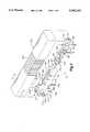
- FIG. 2is an exploded perspective view of the fixator of FIG. 1.
- FIG. 3is a cross-sectional view along line 3-3 in FIG. 1.
- FIG. 4is a cross-sectional view along line 4-4 in FIG. 1 showing how the cover fits over the fixator.
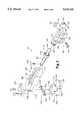
- FIG. 5is a side view of the fixator as it would be mounted on a patients arm.
- FIG. 6is a top view of the fixator as it would be mounted on a patients arm.
- a fixator according to the present inventionis shown generally at 10 in FIGS. 1 and 2.
- An elongate distal member 15forms the distal end of fixator 10.
- a generally planar pin shelf 20 and opposed nut track 25extend along the length of distal member 15.
- An elongate slot 30extends along distal member 15, forming a passage between track 25 and shelf 20.
- At the proximal terminus of distal member 15is a semi-spheroidal cup 35 with externally threaded walls 40. See FIG. 3.
- a set screw 45extends through a portion of distal member 15 into the bottom of cup 35. The axis of set screw 45 is aligned to intersect with the center of the sphere defined by cup 35.
- a pin clamp assembly 50secures two distal pins 55 to distal member 15.
- Pin clamp assembly 50includes a clamp plate 60 with a transverse groove 65 formed at either end to receive distal pins 55.
- Clamp plate 60is urged against shelf 20 by a clamp screw 70 which extends through slot 30 and into nut track 25.
- Clamp screw 70is engaged in a pin clamp nut 75 which rides in nut track 25.
- clamp screw 70is tightened, clamp nut 75 is urged against the bottom of nut track 25 and clamp plate 60 is urged against shelf 20 thereby trapping pins 55 between clamp plate 60 and shelf 20.
- pin clamp assembly 50When clamp screw 70 is loosened, pin clamp assembly 50 is free to travel back and forth along the length of distal member 15, limited only by the extent of nut track 25 and slot 30. Clamp plate 60 can additionally pivot about clamp screw 70. These motions allow pins 55 to be positioned as desired along distal member 15, as well as pivoted in the plane of shelf 20 about the axis of clamp screw 70.
- An elongate medial assembly 80including an elongate medial block 85 and a ball rod 90 is coupled to distal member 15 by a ball 95 at the distal end of ball rod 90.
- Ball 95fits in cup 35 and is retained therein by a ball joint cap 100 to form a ball joint 105.
- Ball joint cap 100is internally threaded and screws down over externally threaded walls 40. When cap 100 is fully seated over cup 35, ball joint 105 should still move relatively freely, allowing ball rod 90 to be positioned anywhere within a cone with an apex at the center of ball 95 and a side angle of approximately 20-30 degrees from the axis of distal member 15. Ball rod 90 can also be rotated about its axis without restriction in ball joint 105.
- Set screw 45fixes the orientation of ball joint 105 when tightened. If set screw 45 is only lightly tightened, it will create some drag on the motion of ball joint 105, while still allowing some movement.
- Ball 95is mounted on a shaft 110, which is in turn telescopically engaged in a longitudinal bore 115 in medial block 85 to make medial assembly 80 adjustable in length.
- An elongate aperture 120opens onto bore 115 from the upper surface of medial block 85.
- a set screw 125 mounted in the proximal end of shaft 110slides in aperture 120 and serves to lock ball rod 90 in place when desired.
- Set screw 125also prevents ball rod 90 from rotating in bore 1A grip 130 is incorporated in medial block 85 generally over bore 115 to accommodate the surgeons fingers.
- the proximal end of medial block 85includes an arcuate rack 135 formed on the end of a protruding ledge 140. Arcuate rack 135 co-acts with a worm gear 145 to control the position of a proximal pin mounting block 150, which is pivotally connected to medial block 85.
- Worm gear 145includes bearing surfaces 155 near each end that ride in a pair of U-shaped guides 160 formed in pin mounting block 150.
- a flared head 165 at each endprevents worm gear 145 from moving side-to-side in pin mounting block 150.
- Proximal and distal transverse openings 170, 175extend through pin mounting block 150 to receive a pair of radial pins 180.
- Each transverse opening 170,175includes an associated set screw 185 to secure radial pins 180.
- a pivot guide 190surrounds the upper portion of distal opening 175 and medial block 85 fits over and pivots around pivot guide 190.
- An arcuate lip 195 on the distal end of pin mounting block 150is received in a matching pivot slot 200 in medial block 85. See FIG. 3. The interaction of lip 195 in pivot slot 200 helps to secure medial block 85 to pin mounting block 150.
- a retainer plate 205is screwed to the proximal end of pin mounting block 150 and extends over ledge 140 to further secure medial block 85 to pin mounting block 150.
- a cover 210is provided to envelope and cloak fixator 10. See FIGS. 1 and 4.
- Cover 210is preferably formed of thin flexible plastic.
- a bellows 215 in the middle of cover 210allows the length to be adjusted to match the length of fixator 10 as installed on the patient.
- cover 210could be formed as two telescoping pieces to achieve the same effect.
- a VelcroTM strap 220 or other fastenermay be use to secure cover 210 to fixator 10.
- the first step in the process of installing fixator 10 on a patientis placing distal pins 55 in the patient's metacarpal and radial pins 180 in the radius.
- Pins 55, 180are installed with the aid of a drill guide, not shown, which includes two spaced-apart parallel guide holes.
- the drill guideinsures that the two pins in each bone are parallel to one another, and generally perpendicular to the longitudinal axis of the bone. In both locations the inter-pin spacing is about 25 mm in the preferred embodiment.
- the two pins in each pairshould generally be as close together as possible to minimize the size of the incision required for placement and allow treatment of small patients, but they must also be far enough apart to provide adequate rigidity for reduction of the fracture.
- fixator 10is attached. In order to place fixator 10 on pins 55, 180, it is desirable to loosen all of the free articulations so fixator 10 may be freely adjusted. With all the free articulations loosened, fixator 10 is quite limber, making the task of installing it on pins 55, 180 relatively quick and easy.
- fixator 10is mounted on the pins, the relative positions of pin clamp assembly 50 along distal member 15 and ball rod 90 in medial block 85 are adjusted so that ball 95 is placed over the flexion/extension axis 225 of the wrist. See FIG. 5. Aligning the pivot axis of ball joint 105 with the flexion axis 225 of the wrist, allowing the patient's wrist to be set to the desired extension angle 230, typically 15 degrees, without disturbing the alignment of previous adjustments. See FIG. 6.
- distal pins 55 along distal member 15is used to accommodate variation in the spacing between the center of the wrist and the metacarpal, which depends on the size of the patient's hand.
- Medial assembly 80similarly, telescopes to fits patients with longer or shorter forearms. Because the telescopic action of medial assembly 80 compensates for part of the variation of spacing between the distal and radial pins among individuals, the overall length of fixator 10 can reduced according to the size of the patient, making it less bulky and less likely to bump or snag on other objects around the patient than a fixator of fixed length.
- distal member 15, and therefore distal pins 55, allowed by ball joint 105allows fixator 10 to accommodate distal and radial pins 55, 180 which are not parallel to each other. This flexibility makes alignment between distal pins 55 and radial pins 180 much less critical.
- the rotationalso allows the supination and pronation of the patients hand to be adjusted. As supination is adjusted, the pivot joint between medial block 85 and pin mounting block 150 must be changed to compensate for displacement of the fracture alignment since the axis of rotation of ball joint 105 is not coincident with the axis of rotation of the wrist.
- distal pins 55 and distal member 15in conjunction with displacement of distal pins 55 along distal member 15, allows the abduction angle 235 of the patient's wrist to be set to the desired value, which is typically 14 degrees. See FIG. 5.
- desired valuetypically 14 degrees. See FIG. 5.
- distal pins 55 on distal member 15 and distal member 15 on ball 95can be used to set the radial/ulnar fracture alignment.
- the length of medial assembly 80is adjusted accordingly. This adjustment leaves ball 95 properly placed over flexion/extension axis 225 of the wrist.
- the dorsal/palmar alignment of the fracture siteis adjusted using worm gear 145 to pivot medial assembly 80 relative to pin mounting block 150.
- each of the articulations in fixator 10can be gradually tightened to provided increasing resistance to movement. This permits quick manual adjustment of the articulations, but otherwise holds them relatively fixed. Once the desired alignment of the fracture and wrist position are established, all of the articulations are locked in place.
Landscapes
- Health & Medical Sciences (AREA)
- Orthopedic Medicine & Surgery (AREA)
- Surgery (AREA)
- Life Sciences & Earth Sciences (AREA)
- Heart & Thoracic Surgery (AREA)
- Nuclear Medicine, Radiotherapy & Molecular Imaging (AREA)
- Engineering & Computer Science (AREA)
- Biomedical Technology (AREA)
- Medical Informatics (AREA)
- Molecular Biology (AREA)
- Animal Behavior & Ethology (AREA)
- General Health & Medical Sciences (AREA)
- Public Health (AREA)
- Veterinary Medicine (AREA)
- Neurology (AREA)
- Surgical Instruments (AREA)
Abstract
Description
Claims (15)
Priority Applications (8)
| Application Number | Priority Date | Filing Date | Title |
|---|---|---|---|
| US08/389,056US5545162A (en) | 1995-02-15 | 1995-02-15 | External fixator for repairing fractures of distal radius and wrist |
| US08/636,326US5662649A (en) | 1995-02-15 | 1996-04-22 | External fixator for repairing fractures of distal radius and wrist |
| US08/715,017US5658283A (en) | 1995-02-15 | 1996-09-17 | External fixator for repairing fractures |
| US09/318,669US6171309B1 (en) | 1995-02-15 | 1999-05-25 | External fixator for repairing fractures of distal radius and wrist |
| US09/318,437US6162224A (en) | 1995-02-15 | 1999-05-25 | External fixator for repairing fractures of distal radius and wrist |
| US13/312,626US20120130433A1 (en) | 1993-01-21 | 2011-12-06 | Axial tension screw |
| US13/851,702US9161793B2 (en) | 1993-01-21 | 2013-03-27 | Axial tension screw |
| US14/885,951US20160038203A1 (en) | 1993-01-21 | 2015-10-16 | Axial tension screw |
Applications Claiming Priority (1)
| Application Number | Priority Date | Filing Date | Title |
|---|---|---|---|
| US08/389,056US5545162A (en) | 1995-02-15 | 1995-02-15 | External fixator for repairing fractures of distal radius and wrist |
Related Child Applications (1)
| Application Number | Title | Priority Date | Filing Date |
|---|---|---|---|
| US08/636,326Continuation-In-PartUS5662649A (en) | 1993-01-21 | 1996-04-22 | External fixator for repairing fractures of distal radius and wrist |
Publications (1)
| Publication Number | Publication Date |
|---|---|
| US5545162Atrue US5545162A (en) | 1996-08-13 |
Family
ID=23536639
Family Applications (1)
| Application Number | Title | Priority Date | Filing Date |
|---|---|---|---|
| US08/389,056Expired - LifetimeUS5545162A (en) | 1993-01-21 | 1995-02-15 | External fixator for repairing fractures of distal radius and wrist |
Country Status (1)
| Country | Link |
|---|---|
| US (1) | US5545162A (en) |
Cited By (51)
| Publication number | Priority date | Publication date | Assignee | Title |
|---|---|---|---|---|
| US6096040A (en)* | 1996-06-14 | 2000-08-01 | Depuy Ace Medical Company | Upper extremity bone plates |
| US6123704A (en)* | 1999-06-22 | 2000-09-26 | Hajianpour; Mohammed A. | Support fixture for setting a fractured distal radius |
| US6197027B1 (en) | 1999-09-08 | 2001-03-06 | Mohammed Ali Hajianpour | Device for external fixation of a fractured radius |
| US6245071B1 (en) | 1999-03-10 | 2001-06-12 | Synthes (U.S.A.) | External fixation device for bone |
| US6423061B1 (en)* | 2000-03-14 | 2002-07-23 | Amei Technologies Inc. | High tibial osteotomy method and apparatus |
| US6428540B1 (en) | 1996-11-13 | 2002-08-06 | Synthes (U.S.A.) | Device for repositioning fractured bone fragments |
| US6585736B2 (en)* | 2001-09-19 | 2003-07-01 | Mohammed A. Hajianpour | Device for external fixation of a fractured radius with simultaneous clamping of multiple pins and with a fixture for applying extension to distal bone fragments |
| US20030149429A1 (en)* | 2002-02-04 | 2003-08-07 | Joseph Ferrante | External fixation system |
| US20030149430A1 (en)* | 2002-02-04 | 2003-08-07 | Joseph Ferrante | Devices, systems, and methods for placing and positioning fixation elements in external fixation systems |
| US6678562B1 (en) | 2000-01-12 | 2004-01-13 | Amei Technologies Inc. | Combined tissue/bone growth stimulator and external fixation device |
| US20040059331A1 (en)* | 2002-09-17 | 2004-03-25 | Visionmed, L.L.C. | Unilateral fixator |
| US20040097922A1 (en)* | 2002-11-14 | 2004-05-20 | Visionmed, L.L.C. | Method for a using fixator device |
| US20040138659A1 (en)* | 2003-01-10 | 2004-07-15 | Ed Austin | External fixation apparatus and method |
| US20040249375A1 (en)* | 2003-06-03 | 2004-12-09 | The John M. Agee Trust | External fixator for colles' fracture |
| US6932086B1 (en) | 2002-12-30 | 2005-08-23 | Mohammed Ali Hajianpour | Support fixture for setting a fractured distal radius |
| US20050245939A1 (en)* | 2002-06-14 | 2005-11-03 | Joseph Ferrante | Device and methods for placing external fixation elements |
| WO2006120482A1 (en)* | 2005-05-12 | 2006-11-16 | Linda Pomeroy | Fixator or splint |
| US7169149B1 (en) | 2003-07-24 | 2007-01-30 | Phoenix Orthopaedic Corporation | Device for external fixation of a proximal fracture of the ulna with a clamped medullar pin and multiple clamped pins holding bone fragments |
| WO2008060825A3 (en)* | 2006-11-14 | 2008-07-17 | Kinglsey R Chin | Multi-component k-wire |
| US20080255554A1 (en)* | 2004-04-01 | 2008-10-16 | Jens Richter | External Fixator for Osteosynthesis or Bone Gap Manipulation |
| US7507240B2 (en) | 2005-03-18 | 2009-03-24 | Ron Anthon Olsen | Adjustable splint for osteosynthesis |
| US20100076436A1 (en)* | 2007-08-16 | 2010-03-25 | Nutek Orthopaedics, Inc. | Apparatus for external fixation of a fractured distal radius with angularly adjustable pin clamping means |
| US7731738B2 (en) | 2005-12-09 | 2010-06-08 | Orthopro, Llc | Cannulated screw |
| US7736380B2 (en) | 2004-12-21 | 2010-06-15 | Rhausler, Inc. | Cervical plate system |
| US7846162B2 (en) | 2005-05-18 | 2010-12-07 | Sonoma Orthopedic Products, Inc. | Minimally invasive actuable bone fixation devices |
| US7909825B2 (en) | 2006-11-22 | 2011-03-22 | Sonoma Orthepedic Products, Inc. | Fracture fixation device, tools and methods |
| US8287541B2 (en) | 2005-05-18 | 2012-10-16 | Sonoma Orthopedic Products, Inc. | Fracture fixation device, tools and methods |
| US8287538B2 (en) | 2008-01-14 | 2012-10-16 | Conventus Orthopaedics, Inc. | Apparatus and methods for fracture repair |
| FR2984723A1 (en)* | 2011-12-27 | 2013-06-28 | Xavier Renard | System for attachment of pin holder on bone portion by e.g. screw, has single-piece body, auxiliary part, and coupling unit that is utilized for coupling/disconnecting auxiliary part and body so that openings are coaxial |
| US8628530B2 (en) | 2007-08-16 | 2014-01-14 | Nutek Orthopedics, Inc. | External fixation apparatus with angularly adjustable drill guiding and pin clamping means |
| US8758343B2 (en) | 2005-04-27 | 2014-06-24 | DePuy Synthes Products, LLC | Bone fixation apparatus |
| US8906022B2 (en) | 2010-03-08 | 2014-12-09 | Conventus Orthopaedics, Inc. | Apparatus and methods for securing a bone implant |
| US8961518B2 (en) | 2010-01-20 | 2015-02-24 | Conventus Orthopaedics, Inc. | Apparatus and methods for bone access and cavity preparation |
| US8961516B2 (en) | 2005-05-18 | 2015-02-24 | Sonoma Orthopedic Products, Inc. | Straight intramedullary fracture fixation devices and methods |
| US9060820B2 (en) | 2005-05-18 | 2015-06-23 | Sonoma Orthopedic Products, Inc. | Segmented intramedullary fracture fixation devices and methods |
| US9155561B2 (en) | 2013-03-06 | 2015-10-13 | Stryker Trauma Sa | Mini-rail external fixator |
| US9155574B2 (en) | 2006-05-17 | 2015-10-13 | Sonoma Orthopedic Products, Inc. | Bone fixation device, tools and methods |
| US9161793B2 (en) | 1993-01-21 | 2015-10-20 | Acumed Llc | Axial tension screw |
| US9320638B2 (en) | 2009-02-20 | 2016-04-26 | Cambfix Limited | Fixator |
| US9730739B2 (en) | 2010-01-15 | 2017-08-15 | Conventus Orthopaedics, Inc. | Rotary-rigid orthopaedic rod |
| US9770272B2 (en) | 2012-12-12 | 2017-09-26 | Wright Medical Technology, Inc. | Orthopedic compression/distraction device |
| US9770278B2 (en) | 2014-01-17 | 2017-09-26 | Arthrex, Inc. | Dual tip guide wire |
| US9814499B2 (en) | 2014-09-30 | 2017-11-14 | Arthrex, Inc. | Intramedullary fracture fixation devices and methods |
| WO2017209710A1 (en) | 2016-06-03 | 2017-12-07 | Demirtas Ahmet Mehmet | An external fixator |
| US9962188B2 (en) | 2013-10-29 | 2018-05-08 | Cardinal Health 247. Inc. | External fixation system and methods of use |
| US10022132B2 (en) | 2013-12-12 | 2018-07-17 | Conventus Orthopaedics, Inc. | Tissue displacement tools and methods |
| US10531896B2 (en) | 2015-08-10 | 2020-01-14 | Stryker European Holdings I, Llc | Distraction tube with wire clamp |
| US10918426B2 (en) | 2017-07-04 | 2021-02-16 | Conventus Orthopaedics, Inc. | Apparatus and methods for treatment of a bone |
| US11596419B2 (en) | 2017-03-09 | 2023-03-07 | Flower Orthopedics Corporation | Plating depth gauge and countersink instrument |
| US11653951B2 (en)* | 2018-11-06 | 2023-05-23 | Ali Moradi | External orthopedic fixation device |
| US12256960B2 (en) | 2019-05-27 | 2025-03-25 | Orthofix S.R.L. | Quick attachment clamp for external fixation systems |
Citations (51)
| Publication number | Priority date | Publication date | Assignee | Title |
|---|---|---|---|---|
| US583455A (en)* | 1897-06-01 | Surgical apparatus | ||
| US1201864A (en)* | 1915-07-06 | 1916-10-17 | George William Overmeyer | Surgical appliance. |
| US1789060A (en)* | 1928-09-29 | 1931-01-13 | King Scheerer Corp | Bone-fracture clamp |
| US2214490A (en)* | 1937-02-08 | 1940-09-10 | Albert A Thomas | Bone-setting splint |
| US2250417A (en)* | 1939-12-02 | 1941-07-22 | Zimmer Mfg Company | Fracture reduction and retention device |
| US2251209A (en)* | 1940-02-17 | 1941-07-29 | Stader Otto | Bone splint |
| US2333033A (en)* | 1943-06-11 | 1943-10-26 | Leslie E Mraz | Bone splint |
| US2371519A (en)* | 1942-11-12 | 1945-03-13 | Herbert H Haynes | Extension and reduction appliance |
| US2391693A (en)* | 1943-12-09 | 1945-12-25 | Zimmer Mfg Company | Surgical splint |
| US2391537A (en)* | 1943-09-27 | 1945-12-25 | Anderson Roger | Ambulatory rotating reduction and fixation splint |
| US2393831A (en)* | 1942-12-29 | 1946-01-29 | Stader Otto | Bone splint |
| US2393694A (en)* | 1945-04-10 | 1946-01-29 | Otto S Kirschner | Surgical apparatus |
| US2393982A (en)* | 1945-01-06 | 1946-02-05 | Josef H Glesen | Fracture reducer |
| US2406987A (en)* | 1943-01-04 | 1946-09-03 | Anderson Roger | Fracture splint |
| US2434431A (en)* | 1944-09-16 | 1948-01-13 | Jack R Pava | Surgical pin guide |
| US2435850A (en)* | 1945-07-16 | 1948-02-10 | John R Siebrandt | Splint and guard construction |
| US2443106A (en)* | 1945-05-10 | 1948-06-08 | Patrick P Grosso | Apparatus for reducing and holding fractures in position |
| US2697433A (en)* | 1951-12-04 | 1954-12-21 | Max A Zehnder | Device for accurately positioning and guiding guide wires used in the nailing of thefemoral neck |
| US3128768A (en)* | 1961-11-24 | 1964-04-14 | Rosemount Eng Co Ltd | Surgical drill |
| US3244170A (en)* | 1962-11-23 | 1966-04-05 | Robert T Mcelvenny | Compression type bone splint |
| US3835849A (en)* | 1973-01-26 | 1974-09-17 | Guire G Mc | Bone clamp and adjustable drill guide |
| US3862631A (en)* | 1973-05-16 | 1975-01-28 | Down Bros | Surgical implants |
| US3961854A (en)* | 1974-05-22 | 1976-06-08 | Henri Jaquet | Apparatus for orienting and maintaining a rod in any direction |
| US3975032A (en)* | 1974-04-15 | 1976-08-17 | Minnesota Mining And Manufacturing Company | Surgical wire driving assembly |
| US4003096A (en)* | 1975-06-17 | 1977-01-18 | Sulzer Brothers Limited | Wrist joint endoprosthesis |
| US4040130A (en)* | 1976-10-12 | 1977-08-09 | Laure Prosthetics, Inc. | Wrist joint prosthesis |
| US4096857A (en)* | 1976-01-20 | 1978-06-27 | Messerschmitt-Boelkow-Blohm Gmbh | Telescopically adjustable surgical instrument |
| US4127119A (en)* | 1976-08-09 | 1978-11-28 | Kronner Richard F | Fracture reducing and joint immobilizing apparatus |
| US4135505A (en)* | 1976-04-30 | 1979-01-23 | National Research Development Corporation | Orthopaedic fracture fixing apparatus |
| US4220146A (en)* | 1979-01-18 | 1980-09-02 | Cloutier Jean Marie | Biplanar joint distractor |
| US4244360A (en)* | 1979-10-22 | 1981-01-13 | Ace Orthopedic Manufacturing, Inc. | Orthopedic fixation pin holder |
| US4271832A (en)* | 1978-07-20 | 1981-06-09 | National Research Development Corporation | Post-fracture stability of limbs |
| US4299212A (en)* | 1977-09-08 | 1981-11-10 | Nederlandsch Central Organisatie voor Toegepast-Natuurwetenschappelijk Onderzoek | External fracture immobilization splint |
| US4308863A (en)* | 1979-10-18 | 1982-01-05 | Ace Orthopedic Manufacturing, Inc. | External fixation device |
| GB2086231A (en)* | 1980-10-31 | 1982-05-12 | Nat Res Dev | Orthopaedic fracture fixation apparatus |
| US4338927A (en)* | 1981-03-16 | 1982-07-13 | Volkov Mstislav V | Device for restoring the function of the lower extremities |
| US4349017A (en)* | 1978-03-31 | 1982-09-14 | Sayegh Antoine Y | Orthopaedic apparatus |
| US4393868A (en)* | 1981-02-20 | 1983-07-19 | Ace Orthopedic Manufacturing Inc. | Colles fracture fixature device |
| US4409970A (en)* | 1981-03-23 | 1983-10-18 | Carrel Edson D | Apparatus and method for treatment of comminuted Colles' fracture |
| US4475546A (en)* | 1983-06-23 | 1984-10-09 | Patton Stephen M | External fixation apparatus |
| US4488542A (en)* | 1981-11-27 | 1984-12-18 | Per Helland | External setting and correction device for the treatment of bone fractures |
| US4548199A (en)* | 1981-11-13 | 1985-10-22 | Agee John M | Fracture splint |
| US4611586A (en)* | 1983-10-06 | 1986-09-16 | John M. Agee | Articulated Colles' fracture splint |
| US4628919A (en)* | 1983-09-09 | 1986-12-16 | Clyburn Terry | Dynamic external fixator and method of use |
| DE3614305A1 (en)* | 1986-04-29 | 1987-11-12 | Baehr Geb Green Judith M | External fixator |
| US4922896A (en)* | 1989-05-05 | 1990-05-08 | John M. Agee | Colles' fracture splint |
| US4988349A (en)* | 1987-01-21 | 1991-01-29 | Orthofix S.R.L. | Device for osteosynthesis |
| US5254078A (en)* | 1991-06-03 | 1993-10-19 | Innovation Sports, Inc. | Wrist brace |
| US5304177A (en)* | 1992-06-26 | 1994-04-19 | Dietmar Pennig | Auxiliary device for osteosynthesis |
| US5320622A (en)* | 1992-07-28 | 1994-06-14 | Orthofix S.R.L. | Dynamic axial splint |
| US5320623A (en)* | 1991-07-16 | 1994-06-14 | Orthofix S.R.1. | Clamping coupling for an external fixator |
- 1995
- 1995-02-15USUS08/389,056patent/US5545162A/ennot_activeExpired - Lifetime
Patent Citations (51)
| Publication number | Priority date | Publication date | Assignee | Title |
|---|---|---|---|---|
| US583455A (en)* | 1897-06-01 | Surgical apparatus | ||
| US1201864A (en)* | 1915-07-06 | 1916-10-17 | George William Overmeyer | Surgical appliance. |
| US1789060A (en)* | 1928-09-29 | 1931-01-13 | King Scheerer Corp | Bone-fracture clamp |
| US2214490A (en)* | 1937-02-08 | 1940-09-10 | Albert A Thomas | Bone-setting splint |
| US2250417A (en)* | 1939-12-02 | 1941-07-22 | Zimmer Mfg Company | Fracture reduction and retention device |
| US2251209A (en)* | 1940-02-17 | 1941-07-29 | Stader Otto | Bone splint |
| US2371519A (en)* | 1942-11-12 | 1945-03-13 | Herbert H Haynes | Extension and reduction appliance |
| US2393831A (en)* | 1942-12-29 | 1946-01-29 | Stader Otto | Bone splint |
| US2406987A (en)* | 1943-01-04 | 1946-09-03 | Anderson Roger | Fracture splint |
| US2333033A (en)* | 1943-06-11 | 1943-10-26 | Leslie E Mraz | Bone splint |
| US2391537A (en)* | 1943-09-27 | 1945-12-25 | Anderson Roger | Ambulatory rotating reduction and fixation splint |
| US2391693A (en)* | 1943-12-09 | 1945-12-25 | Zimmer Mfg Company | Surgical splint |
| US2434431A (en)* | 1944-09-16 | 1948-01-13 | Jack R Pava | Surgical pin guide |
| US2393982A (en)* | 1945-01-06 | 1946-02-05 | Josef H Glesen | Fracture reducer |
| US2393694A (en)* | 1945-04-10 | 1946-01-29 | Otto S Kirschner | Surgical apparatus |
| US2443106A (en)* | 1945-05-10 | 1948-06-08 | Patrick P Grosso | Apparatus for reducing and holding fractures in position |
| US2435850A (en)* | 1945-07-16 | 1948-02-10 | John R Siebrandt | Splint and guard construction |
| US2697433A (en)* | 1951-12-04 | 1954-12-21 | Max A Zehnder | Device for accurately positioning and guiding guide wires used in the nailing of thefemoral neck |
| US3128768A (en)* | 1961-11-24 | 1964-04-14 | Rosemount Eng Co Ltd | Surgical drill |
| US3244170A (en)* | 1962-11-23 | 1966-04-05 | Robert T Mcelvenny | Compression type bone splint |
| US3835849A (en)* | 1973-01-26 | 1974-09-17 | Guire G Mc | Bone clamp and adjustable drill guide |
| US3862631A (en)* | 1973-05-16 | 1975-01-28 | Down Bros | Surgical implants |
| US3975032A (en)* | 1974-04-15 | 1976-08-17 | Minnesota Mining And Manufacturing Company | Surgical wire driving assembly |
| US3961854A (en)* | 1974-05-22 | 1976-06-08 | Henri Jaquet | Apparatus for orienting and maintaining a rod in any direction |
| US4003096A (en)* | 1975-06-17 | 1977-01-18 | Sulzer Brothers Limited | Wrist joint endoprosthesis |
| US4096857A (en)* | 1976-01-20 | 1978-06-27 | Messerschmitt-Boelkow-Blohm Gmbh | Telescopically adjustable surgical instrument |
| US4135505A (en)* | 1976-04-30 | 1979-01-23 | National Research Development Corporation | Orthopaedic fracture fixing apparatus |
| US4127119A (en)* | 1976-08-09 | 1978-11-28 | Kronner Richard F | Fracture reducing and joint immobilizing apparatus |
| US4040130A (en)* | 1976-10-12 | 1977-08-09 | Laure Prosthetics, Inc. | Wrist joint prosthesis |
| US4299212A (en)* | 1977-09-08 | 1981-11-10 | Nederlandsch Central Organisatie voor Toegepast-Natuurwetenschappelijk Onderzoek | External fracture immobilization splint |
| US4349017A (en)* | 1978-03-31 | 1982-09-14 | Sayegh Antoine Y | Orthopaedic apparatus |
| US4271832A (en)* | 1978-07-20 | 1981-06-09 | National Research Development Corporation | Post-fracture stability of limbs |
| US4220146A (en)* | 1979-01-18 | 1980-09-02 | Cloutier Jean Marie | Biplanar joint distractor |
| US4308863A (en)* | 1979-10-18 | 1982-01-05 | Ace Orthopedic Manufacturing, Inc. | External fixation device |
| US4244360A (en)* | 1979-10-22 | 1981-01-13 | Ace Orthopedic Manufacturing, Inc. | Orthopedic fixation pin holder |
| GB2086231A (en)* | 1980-10-31 | 1982-05-12 | Nat Res Dev | Orthopaedic fracture fixation apparatus |
| US4393868A (en)* | 1981-02-20 | 1983-07-19 | Ace Orthopedic Manufacturing Inc. | Colles fracture fixature device |
| US4338927A (en)* | 1981-03-16 | 1982-07-13 | Volkov Mstislav V | Device for restoring the function of the lower extremities |
| US4409970A (en)* | 1981-03-23 | 1983-10-18 | Carrel Edson D | Apparatus and method for treatment of comminuted Colles' fracture |
| US4548199A (en)* | 1981-11-13 | 1985-10-22 | Agee John M | Fracture splint |
| US4488542A (en)* | 1981-11-27 | 1984-12-18 | Per Helland | External setting and correction device for the treatment of bone fractures |
| US4475546A (en)* | 1983-06-23 | 1984-10-09 | Patton Stephen M | External fixation apparatus |
| US4628919A (en)* | 1983-09-09 | 1986-12-16 | Clyburn Terry | Dynamic external fixator and method of use |
| US4611586A (en)* | 1983-10-06 | 1986-09-16 | John M. Agee | Articulated Colles' fracture splint |
| DE3614305A1 (en)* | 1986-04-29 | 1987-11-12 | Baehr Geb Green Judith M | External fixator |
| US4988349A (en)* | 1987-01-21 | 1991-01-29 | Orthofix S.R.L. | Device for osteosynthesis |
| US4922896A (en)* | 1989-05-05 | 1990-05-08 | John M. Agee | Colles' fracture splint |
| US5254078A (en)* | 1991-06-03 | 1993-10-19 | Innovation Sports, Inc. | Wrist brace |
| US5320623A (en)* | 1991-07-16 | 1994-06-14 | Orthofix S.R.1. | Clamping coupling for an external fixator |
| US5304177A (en)* | 1992-06-26 | 1994-04-19 | Dietmar Pennig | Auxiliary device for osteosynthesis |
| US5320622A (en)* | 1992-07-28 | 1994-06-14 | Orthofix S.R.L. | Dynamic axial splint |
Non-Patent Citations (2)
| Title |
|---|
| "Distal Radius Fractures," by John M. Agee, MD, External Fixation, vol. 9, No. 4, Nov. 1993, p. 577. |
| Distal Radius Fractures, by John M. Agee, MD, External Fixation, vol. 9, No. 4, Nov. 1993, p. 577.* |
Cited By (90)
| Publication number | Priority date | Publication date | Assignee | Title |
|---|---|---|---|---|
| US9161793B2 (en) | 1993-01-21 | 2015-10-20 | Acumed Llc | Axial tension screw |
| US6096040A (en)* | 1996-06-14 | 2000-08-01 | Depuy Ace Medical Company | Upper extremity bone plates |
| US6428540B1 (en) | 1996-11-13 | 2002-08-06 | Synthes (U.S.A.) | Device for repositioning fractured bone fragments |
| US6245071B1 (en) | 1999-03-10 | 2001-06-12 | Synthes (U.S.A.) | External fixation device for bone |
| US6123704A (en)* | 1999-06-22 | 2000-09-26 | Hajianpour; Mohammed A. | Support fixture for setting a fractured distal radius |
| US6197027B1 (en) | 1999-09-08 | 2001-03-06 | Mohammed Ali Hajianpour | Device for external fixation of a fractured radius |
| US6678562B1 (en) | 2000-01-12 | 2004-01-13 | Amei Technologies Inc. | Combined tissue/bone growth stimulator and external fixation device |
| US6423061B1 (en)* | 2000-03-14 | 2002-07-23 | Amei Technologies Inc. | High tibial osteotomy method and apparatus |
| US20020164905A1 (en)* | 2000-03-14 | 2002-11-07 | Amei Technologies Inc., A Delaware Corporation | Osteotomy guide and method |
| US6585736B2 (en)* | 2001-09-19 | 2003-07-01 | Mohammed A. Hajianpour | Device for external fixation of a fractured radius with simultaneous clamping of multiple pins and with a fixture for applying extension to distal bone fragments |
| US7153302B1 (en)* | 2001-09-19 | 2006-12-26 | Phoenix Orthopaedic Corporation | Device for external fixation of bone fractures with clamping of multiple pins and with a fixture for applying extension to bone fragments |
| US7004943B2 (en) | 2002-02-04 | 2006-02-28 | Smith & Nephew, Inc. | Devices, systems, and methods for placing and positioning fixation elements in external fixation systems |
| US20030149430A1 (en)* | 2002-02-04 | 2003-08-07 | Joseph Ferrante | Devices, systems, and methods for placing and positioning fixation elements in external fixation systems |
| US20030149429A1 (en)* | 2002-02-04 | 2003-08-07 | Joseph Ferrante | External fixation system |
| US7887537B2 (en) | 2002-02-04 | 2011-02-15 | Smith & Nephew, Inc. | External fixation system |
| US20050119656A1 (en)* | 2002-02-04 | 2005-06-02 | Joseph Ferrante | External fixation system |
| US7048735B2 (en)* | 2002-02-04 | 2006-05-23 | Smith & Nephew | External fixation system |
| US20050245939A1 (en)* | 2002-06-14 | 2005-11-03 | Joseph Ferrante | Device and methods for placing external fixation elements |
| US7758582B2 (en) | 2002-06-14 | 2010-07-20 | Smith & Nephew, Inc. | Device and methods for placing external fixation elements |
| US20070282338A1 (en)* | 2002-09-17 | 2007-12-06 | Ebi, L.P. | Unilateral fixator |
| US8388619B2 (en) | 2002-09-17 | 2013-03-05 | Sixfix Inc. | Unilateral fixator |
| US20040059331A1 (en)* | 2002-09-17 | 2004-03-25 | Visionmed, L.L.C. | Unilateral fixator |
| US7282052B2 (en) | 2002-09-17 | 2007-10-16 | Ebi, L.P. | Unilateral fixator |
| US20040097922A1 (en)* | 2002-11-14 | 2004-05-20 | Visionmed, L.L.C. | Method for a using fixator device |
| US20110103676A1 (en)* | 2002-11-14 | 2011-05-05 | Extraortho, Inc. | Method for using a fixator device |
| US8419732B2 (en) | 2002-11-14 | 2013-04-16 | Sixfix, Inc. | Method for using a fixator device |
| US6932086B1 (en) | 2002-12-30 | 2005-08-23 | Mohammed Ali Hajianpour | Support fixture for setting a fractured distal radius |
| US8382755B2 (en) | 2003-01-10 | 2013-02-26 | Smith & Nephew, Inc. | External fixation apparatus and method |
| US20070255280A1 (en)* | 2003-01-10 | 2007-11-01 | Smith & Nephew, Inc. | External fixation apparatus and method |
| US7608074B2 (en) | 2003-01-10 | 2009-10-27 | Smith & Nephew, Inc. | External fixation apparatus and method |
| US20040138659A1 (en)* | 2003-01-10 | 2004-07-15 | Ed Austin | External fixation apparatus and method |
| US7291148B2 (en) | 2003-06-03 | 2007-11-06 | John M. Agee Trustee Of The John M. Agee Trust | External fixator for Colles' fracture |
| US20040249375A1 (en)* | 2003-06-03 | 2004-12-09 | The John M. Agee Trust | External fixator for colles' fracture |
| US7169149B1 (en) | 2003-07-24 | 2007-01-30 | Phoenix Orthopaedic Corporation | Device for external fixation of a proximal fracture of the ulna with a clamped medullar pin and multiple clamped pins holding bone fragments |
| US20080255554A1 (en)* | 2004-04-01 | 2008-10-16 | Jens Richter | External Fixator for Osteosynthesis or Bone Gap Manipulation |
| US7736380B2 (en) | 2004-12-21 | 2010-06-15 | Rhausler, Inc. | Cervical plate system |
| US7588571B2 (en) | 2005-03-18 | 2009-09-15 | Ron Anthon Olsen | Adjustable splint for osteosynthesis with modular joint |
| US7575575B2 (en) | 2005-03-18 | 2009-08-18 | Ron Anthon Olsen | Adjustable splint for osteosynthesis with modular components |
| US7507240B2 (en) | 2005-03-18 | 2009-03-24 | Ron Anthon Olsen | Adjustable splint for osteosynthesis |
| US8758343B2 (en) | 2005-04-27 | 2014-06-24 | DePuy Synthes Products, LLC | Bone fixation apparatus |
| CN101198283B (en)* | 2005-05-12 | 2010-05-19 | 琳达·波默罗伊 | Anchors or splints |
| US7841998B2 (en) | 2005-05-12 | 2010-11-30 | Linda Pomeroy | Fixator or splint |
| JP2008539925A (en)* | 2005-05-12 | 2008-11-20 | リンダ・ポメロイ | Sprint or fixing device |
| US20080200855A1 (en)* | 2005-05-12 | 2008-08-21 | Linda Pomeroy | Fixator or Splint |
| WO2006120482A1 (en)* | 2005-05-12 | 2006-11-16 | Linda Pomeroy | Fixator or splint |
| US7914533B2 (en) | 2005-05-18 | 2011-03-29 | Sonoma Orthopedic Products, Inc. | Minimally invasive actuable bone fixation devices |
| US7846162B2 (en) | 2005-05-18 | 2010-12-07 | Sonoma Orthopedic Products, Inc. | Minimally invasive actuable bone fixation devices |
| US7942875B2 (en) | 2005-05-18 | 2011-05-17 | Sonoma Orthopedic Products, Inc. | Methods of using minimally invasive actuable bone fixation devices |
| US8287541B2 (en) | 2005-05-18 | 2012-10-16 | Sonoma Orthopedic Products, Inc. | Fracture fixation device, tools and methods |
| US8287539B2 (en) | 2005-05-18 | 2012-10-16 | Sonoma Orthopedic Products, Inc. | Fracture fixation device, tools and methods |
| US9060820B2 (en) | 2005-05-18 | 2015-06-23 | Sonoma Orthopedic Products, Inc. | Segmented intramedullary fracture fixation devices and methods |
| US8961516B2 (en) | 2005-05-18 | 2015-02-24 | Sonoma Orthopedic Products, Inc. | Straight intramedullary fracture fixation devices and methods |
| US7731738B2 (en) | 2005-12-09 | 2010-06-08 | Orthopro, Llc | Cannulated screw |
| US9155574B2 (en) | 2006-05-17 | 2015-10-13 | Sonoma Orthopedic Products, Inc. | Bone fixation device, tools and methods |
| WO2008060825A3 (en)* | 2006-11-14 | 2008-07-17 | Kinglsey R Chin | Multi-component k-wire |
| US7909825B2 (en) | 2006-11-22 | 2011-03-22 | Sonoma Orthepedic Products, Inc. | Fracture fixation device, tools and methods |
| US8439917B2 (en) | 2006-11-22 | 2013-05-14 | Sonoma Orthopedic Products, Inc. | Fracture fixation device, tools and methods |
| US9259250B2 (en) | 2006-11-22 | 2016-02-16 | Sonoma Orthopedic Products, Inc. | Fracture fixation device, tools and methods |
| US8123747B2 (en) | 2007-08-16 | 2012-02-28 | Nutek Orthopaedics, Inc. | Apparatus for external fixation of a fractured distal radius with angularly adjustable pin clamping means |
| US20100076436A1 (en)* | 2007-08-16 | 2010-03-25 | Nutek Orthopaedics, Inc. | Apparatus for external fixation of a fractured distal radius with angularly adjustable pin clamping means |
| US8628530B2 (en) | 2007-08-16 | 2014-01-14 | Nutek Orthopedics, Inc. | External fixation apparatus with angularly adjustable drill guiding and pin clamping means |
| US9517093B2 (en) | 2008-01-14 | 2016-12-13 | Conventus Orthopaedics, Inc. | Apparatus and methods for fracture repair |
| US9788870B2 (en) | 2008-01-14 | 2017-10-17 | Conventus Orthopaedics, Inc. | Apparatus and methods for fracture repair |
| US8287538B2 (en) | 2008-01-14 | 2012-10-16 | Conventus Orthopaedics, Inc. | Apparatus and methods for fracture repair |
| US11399878B2 (en) | 2008-01-14 | 2022-08-02 | Conventus Orthopaedics, Inc. | Apparatus and methods for fracture repair |
| US10603087B2 (en) | 2008-01-14 | 2020-03-31 | Conventus Orthopaedics, Inc. | Apparatus and methods for fracture repair |
| US9320638B2 (en) | 2009-02-20 | 2016-04-26 | Cambfix Limited | Fixator |
| US9730739B2 (en) | 2010-01-15 | 2017-08-15 | Conventus Orthopaedics, Inc. | Rotary-rigid orthopaedic rod |
| US8961518B2 (en) | 2010-01-20 | 2015-02-24 | Conventus Orthopaedics, Inc. | Apparatus and methods for bone access and cavity preparation |
| US9848889B2 (en) | 2010-01-20 | 2017-12-26 | Conventus Orthopaedics, Inc. | Apparatus and methods for bone access and cavity preparation |
| US8906022B2 (en) | 2010-03-08 | 2014-12-09 | Conventus Orthopaedics, Inc. | Apparatus and methods for securing a bone implant |
| US9993277B2 (en) | 2010-03-08 | 2018-06-12 | Conventus Orthopaedics, Inc. | Apparatus and methods for securing a bone implant |
| FR2984723A1 (en)* | 2011-12-27 | 2013-06-28 | Xavier Renard | System for attachment of pin holder on bone portion by e.g. screw, has single-piece body, auxiliary part, and coupling unit that is utilized for coupling/disconnecting auxiliary part and body so that openings are coaxial |
| US10631900B2 (en) | 2012-12-12 | 2020-04-28 | Wright Medical Technology, Inc. | Orthopedic compression/distraction device |
| US9770272B2 (en) | 2012-12-12 | 2017-09-26 | Wright Medical Technology, Inc. | Orthopedic compression/distraction device |
| US9622781B2 (en) | 2013-03-06 | 2017-04-18 | Stryker European Holdings I, Llc | Mini-rail external fixator |
| US9155561B2 (en) | 2013-03-06 | 2015-10-13 | Stryker Trauma Sa | Mini-rail external fixator |
| US9962188B2 (en) | 2013-10-29 | 2018-05-08 | Cardinal Health 247. Inc. | External fixation system and methods of use |
| US10022132B2 (en) | 2013-12-12 | 2018-07-17 | Conventus Orthopaedics, Inc. | Tissue displacement tools and methods |
| US10076342B2 (en) | 2013-12-12 | 2018-09-18 | Conventus Orthopaedics, Inc. | Tissue displacement tools and methods |
| US9770278B2 (en) | 2014-01-17 | 2017-09-26 | Arthrex, Inc. | Dual tip guide wire |
| US9814499B2 (en) | 2014-09-30 | 2017-11-14 | Arthrex, Inc. | Intramedullary fracture fixation devices and methods |
| US10548648B2 (en) | 2014-09-30 | 2020-02-04 | Arthrex, Inc. | Intramedullary fracture fixation devices and methods |
| US10531896B2 (en) | 2015-08-10 | 2020-01-14 | Stryker European Holdings I, Llc | Distraction tube with wire clamp |
| US10925645B2 (en) | 2016-06-03 | 2021-02-23 | Ahmet Mehmet DEMIRTAS | External fixator |
| WO2017209710A1 (en) | 2016-06-03 | 2017-12-07 | Demirtas Ahmet Mehmet | An external fixator |
| US11596419B2 (en) | 2017-03-09 | 2023-03-07 | Flower Orthopedics Corporation | Plating depth gauge and countersink instrument |
| US10918426B2 (en) | 2017-07-04 | 2021-02-16 | Conventus Orthopaedics, Inc. | Apparatus and methods for treatment of a bone |
| US11653951B2 (en)* | 2018-11-06 | 2023-05-23 | Ali Moradi | External orthopedic fixation device |
| US12256960B2 (en) | 2019-05-27 | 2025-03-25 | Orthofix S.R.L. | Quick attachment clamp for external fixation systems |
Similar Documents
| Publication | Publication Date | Title |
|---|---|---|
| US5545162A (en) | External fixator for repairing fractures of distal radius and wrist | |
| US6171309B1 (en) | External fixator for repairing fractures of distal radius and wrist | |
| US5662649A (en) | External fixator for repairing fractures of distal radius and wrist | |
| US6162224A (en) | External fixator for repairing fractures of distal radius and wrist | |
| US5976134A (en) | External fixator for repairing fractures | |
| US5658283A (en) | External fixator for repairing fractures | |
| US7147640B2 (en) | External fixator | |
| KR920010760B1 (en) | Dynamic external fixation device for the wrist | |
| US5376091A (en) | Dynamic finger support | |
| US5100403A (en) | Dynamic elbow support | |
| US6245071B1 (en) | External fixation device for bone | |
| US5372597A (en) | Supination-pronation device | |
| US5102411A (en) | Dynamic elbow support | |
| US7291148B2 (en) | External fixator for Colles' fracture | |
| US6063087A (en) | Method and apparatus for increasing the range of motion of fingers suffering from a limited range of motion, through an external force transmitted to the skeleton | |
| US4881532A (en) | Orthopedic hip hinge providing adjustment for abduction | |
| US20090125068A1 (en) | Apparatus for Dynamic External Fixation of Distal Radius and Wrist Fractures | |
| US5391167A (en) | Articulating external fixation device | |
| JPS62286455A (en) | Dynamic bone fixing external apparatus | |
| EP0996382A1 (en) | Distraction apparatus | |
| JPH0326251A (en) | Action control mechanism for orthopedic sup- porter | |
| AU660309B2 (en) | Dynamic joint support | |
| US5954721A (en) | Devices for passive motion of joints under traction | |
| CN112754630A (en) | Elbow joint hinge type external fixing support with rotatable forearm | |
| JPH07163609A (en) | Dynamic joint support equipment and its fixation method |
Legal Events
| Date | Code | Title | Description |
|---|---|---|---|
| STCF | Information on status: patent grant | Free format text:PATENTED CASE | |
| AS | Assignment | Owner name:ACUMED, INC, OREGON Free format text:ASSIGNMENT OF ASSIGNORS INTEREST;ASSIGNOR:HUEBNER, RANDALL J.;REEL/FRAME:010052/0462 Effective date:19990421 | |
| FEPP | Fee payment procedure | Free format text:PAT HLDR NO LONGER CLAIMS SMALL ENT STAT AS INDIV INVENTOR (ORIGINAL EVENT CODE: LSM1); ENTITY STATUS OF PATENT OWNER: LARGE ENTITY | |
| FPAY | Fee payment | Year of fee payment:4 | |
| FEPP | Fee payment procedure | Free format text:PAYOR NUMBER ASSIGNED (ORIGINAL EVENT CODE: ASPN); ENTITY STATUS OF PATENT OWNER: LARGE ENTITY | |
| FPAY | Fee payment | Year of fee payment:8 | |
| AS | Assignment | Owner name:ACUMED OPERATING LLC, OREGON Free format text:CONTRIBUTION AGREEMENT;ASSIGNOR:ACUMED, INC.;REEL/FRAME:014662/0262 Effective date:20021209 | |
| AS | Assignment | Owner name:ACUMED LLC, OREGON Free format text:CHANGE OF NAME;ASSIGNOR:ACUMED OPERATING LLC;REEL/FRAME:014669/0497 Effective date:20021210 | |
| REMI | Maintenance fee reminder mailed | ||
| FPAY | Fee payment | Year of fee payment:12 | |
| SULP | Surcharge for late payment | Year of fee payment:11 |