US5544645A - Combination water heating and space heating apparatus - Google Patents
Combination water heating and space heating apparatusDownload PDFInfo
- Publication number
- US5544645A US5544645AUS08/296,112US29611294AUS5544645AUS 5544645 AUS5544645 AUS 5544645AUS 29611294 AUS29611294 AUS 29611294AUS 5544645 AUS5544645 AUS 5544645A
- Authority
- US
- United States
- Prior art keywords
- water
- tank
- air
- conduit
- combustion chamber
- Prior art date
- Legal status (The legal status is an assumption and is not a legal conclusion. Google has not performed a legal analysis and makes no representation as to the accuracy of the status listed.)
- Expired - Lifetime
Links
Images


Classifications
- F—MECHANICAL ENGINEERING; LIGHTING; HEATING; WEAPONS; BLASTING
- F24—HEATING; RANGES; VENTILATING
- F24D—DOMESTIC- OR SPACE-HEATING SYSTEMS, e.g. CENTRAL HEATING SYSTEMS; DOMESTIC HOT-WATER SUPPLY SYSTEMS; ELEMENTS OR COMPONENTS THEREFOR
- F24D19/00—Details
- F24D19/10—Arrangement or mounting of control or safety devices
- F24D19/1006—Arrangement or mounting of control or safety devices for water heating systems
- F24D19/1066—Arrangement or mounting of control or safety devices for water heating systems for the combination of central heating and domestic hot water
- F—MECHANICAL ENGINEERING; LIGHTING; HEATING; WEAPONS; BLASTING
- F24—HEATING; RANGES; VENTILATING
- F24H—FLUID HEATERS, e.g. WATER OR AIR HEATERS, HAVING HEAT-GENERATING MEANS, e.g. HEAT PUMPS, IN GENERAL
- F24H1/00—Water heaters, e.g. boilers, continuous-flow heaters or water-storage heaters
- F24H1/18—Water-storage heaters
- F24H1/20—Water-storage heaters with immersed heating elements, e.g. electric elements or furnace tubes
- F24H1/205—Water-storage heaters with immersed heating elements, e.g. electric elements or furnace tubes with furnace tubes
- F24H1/206—Water-storage heaters with immersed heating elements, e.g. electric elements or furnace tubes with furnace tubes with submerged combustion chamber
- F—MECHANICAL ENGINEERING; LIGHTING; HEATING; WEAPONS; BLASTING
- F24—HEATING; RANGES; VENTILATING
- F24H—FLUID HEATERS, e.g. WATER OR AIR HEATERS, HAVING HEAT-GENERATING MEANS, e.g. HEAT PUMPS, IN GENERAL
- F24H15/00—Control of fluid heaters
- F24H15/10—Control of fluid heaters characterised by the purpose of the control
- F24H15/174—Supplying heated water with desired temperature or desired range of temperature
- F—MECHANICAL ENGINEERING; LIGHTING; HEATING; WEAPONS; BLASTING
- F24—HEATING; RANGES; VENTILATING
- F24H—FLUID HEATERS, e.g. WATER OR AIR HEATERS, HAVING HEAT-GENERATING MEANS, e.g. HEAT PUMPS, IN GENERAL
- F24H15/00—Control of fluid heaters
- F24H15/20—Control of fluid heaters characterised by control inputs
- F24H15/212—Temperature of the water
- F24H15/223—Temperature of the water in the water storage tank
- F—MECHANICAL ENGINEERING; LIGHTING; HEATING; WEAPONS; BLASTING
- F24—HEATING; RANGES; VENTILATING
- F24H—FLUID HEATERS, e.g. WATER OR AIR HEATERS, HAVING HEAT-GENERATING MEANS, e.g. HEAT PUMPS, IN GENERAL
- F24H15/00—Control of fluid heaters
- F24H15/20—Control of fluid heaters characterised by control inputs
- F24H15/242—Pressure
- F—MECHANICAL ENGINEERING; LIGHTING; HEATING; WEAPONS; BLASTING
- F24—HEATING; RANGES; VENTILATING
- F24H—FLUID HEATERS, e.g. WATER OR AIR HEATERS, HAVING HEAT-GENERATING MEANS, e.g. HEAT PUMPS, IN GENERAL
- F24H15/00—Control of fluid heaters
- F24H15/20—Control of fluid heaters characterised by control inputs
- F24H15/254—Room temperature
- F—MECHANICAL ENGINEERING; LIGHTING; HEATING; WEAPONS; BLASTING
- F24—HEATING; RANGES; VENTILATING
- F24H—FLUID HEATERS, e.g. WATER OR AIR HEATERS, HAVING HEAT-GENERATING MEANS, e.g. HEAT PUMPS, IN GENERAL
- F24H15/00—Control of fluid heaters
- F24H15/30—Control of fluid heaters characterised by control outputs; characterised by the components to be controlled
- F24H15/305—Control of valves
- F24H15/31—Control of valves of valves having only one inlet port and one outlet port, e.g. flow rate regulating valves
- F—MECHANICAL ENGINEERING; LIGHTING; HEATING; WEAPONS; BLASTING
- F24—HEATING; RANGES; VENTILATING
- F24H—FLUID HEATERS, e.g. WATER OR AIR HEATERS, HAVING HEAT-GENERATING MEANS, e.g. HEAT PUMPS, IN GENERAL
- F24H15/00—Control of fluid heaters
- F24H15/30—Control of fluid heaters characterised by control outputs; characterised by the components to be controlled
- F24H15/335—Control of pumps, e.g. on-off control
- F—MECHANICAL ENGINEERING; LIGHTING; HEATING; WEAPONS; BLASTING
- F24—HEATING; RANGES; VENTILATING
- F24H—FLUID HEATERS, e.g. WATER OR AIR HEATERS, HAVING HEAT-GENERATING MEANS, e.g. HEAT PUMPS, IN GENERAL
- F24H15/00—Control of fluid heaters
- F24H15/30—Control of fluid heaters characterised by control outputs; characterised by the components to be controlled
- F24H15/345—Control of fans, e.g. on-off control
- F24H15/35—Control of the speed of fans
- F—MECHANICAL ENGINEERING; LIGHTING; HEATING; WEAPONS; BLASTING
- F24—HEATING; RANGES; VENTILATING
- F24H—FLUID HEATERS, e.g. WATER OR AIR HEATERS, HAVING HEAT-GENERATING MEANS, e.g. HEAT PUMPS, IN GENERAL
- F24H15/00—Control of fluid heaters
- F24H15/30—Control of fluid heaters characterised by control outputs; characterised by the components to be controlled
- F24H15/355—Control of heat-generating means in heaters
- F24H15/36—Control of heat-generating means in heaters of burners
- F—MECHANICAL ENGINEERING; LIGHTING; HEATING; WEAPONS; BLASTING
- F24—HEATING; RANGES; VENTILATING
- F24H—FLUID HEATERS, e.g. WATER OR AIR HEATERS, HAVING HEAT-GENERATING MEANS, e.g. HEAT PUMPS, IN GENERAL
- F24H15/00—Control of fluid heaters
- F24H15/40—Control of fluid heaters characterised by the type of controllers
- F24H15/414—Control of fluid heaters characterised by the type of controllers using electronic processing, e.g. computer-based
- F—MECHANICAL ENGINEERING; LIGHTING; HEATING; WEAPONS; BLASTING
- F24—HEATING; RANGES; VENTILATING
- F24H—FLUID HEATERS, e.g. WATER OR AIR HEATERS, HAVING HEAT-GENERATING MEANS, e.g. HEAT PUMPS, IN GENERAL
- F24H15/00—Control of fluid heaters
- F24H15/40—Control of fluid heaters characterised by the type of controllers
- F24H15/486—Control of fluid heaters characterised by the type of controllers using timers
- F—MECHANICAL ENGINEERING; LIGHTING; HEATING; WEAPONS; BLASTING
- F24—HEATING; RANGES; VENTILATING
- F24H—FLUID HEATERS, e.g. WATER OR AIR HEATERS, HAVING HEAT-GENERATING MEANS, e.g. HEAT PUMPS, IN GENERAL
- F24H6/00—Combined water and air heaters
- F—MECHANICAL ENGINEERING; LIGHTING; HEATING; WEAPONS; BLASTING
- F24—HEATING; RANGES; VENTILATING
- F24H—FLUID HEATERS, e.g. WATER OR AIR HEATERS, HAVING HEAT-GENERATING MEANS, e.g. HEAT PUMPS, IN GENERAL
- F24H15/00—Control of fluid heaters
- F24H15/10—Control of fluid heaters characterised by the purpose of the control
- F24H15/14—Cleaning; Sterilising; Preventing contamination by bacteria or microorganisms, e.g. by replacing fluid in tanks or conduits
Definitions
- This inventionrelates generally to heating apparatus and in particular to combination water heating and space heating apparatus.
- Combination water heating and space heating apparatusas shown, for example, in U.S. Pat. Nos. 4,541,410, 4,641,631 and 4,766,883, are known in the art.
- hot wateris circulated between a hot water storage tank and an hydronic heat exchanger coil located in an air supply duct to heat the air passing over the heat exchanger coil, thereby providing heated air to an indoor space.
- One problem associated with such prior art combination apparatusis the allocation of hot water between space heating and the normal hot water supply (e.g., hot water for domestic use). If there is a concomitant demand for space heating and for domestic hot water (e.g., showers, laundry, dishwasher, etc.), the hot water supply may be insufficient to satisfy the demand.
- combustion chamber of the water heateris typically located at the bottom of the tank.
- water in the tankis in direct contact with the sides and top of the combustion chamber, but not the bottom, thereby detracting from the efficiency of the apparatus.
- water heated at the bottom of the tankrises to the top of the tank and is replaced by colder water sinking to the bottom of the tank.
- This natural convectionis advantageous in terms of circulating water throughout the tank, but is disadvantageous in terms of being able to rapidly heat water to a desired temperature for immediate use (e.g., for space heating).
- the apparatusincludes a water heating unit and a space heating unit.
- the water heating unithas a water storage tank, heating means for heating water stored in the tank and first temperature sensing means for sensing water temperature in the tank and for providing a first electrical signal in response to the water temperature being at least a first temperature increment below a first temperature setpoint corresponding to a desired water temperature.
- the first electrical signalindicates a demand for water heating.
- the space heating unithas an air duct for supplying air to an indoor space, a heat exchanger for heating the supply air, air moving means for moving air over the heat exchanger and second temperature sensing means for sensing air temperature in the indoor space and for providing a second electrical signal in response to the air temperature being at least a second temperature increment below a second temperature setpoint corresponding to a desired air temperature.
- the second electrical signalindicates a demand for space heating.
- Water circulation meansis provided for circulating water between the tank and the heat exchanger in the supply air duct.
- the apparatusfurther includes control means adapted to control the heating means, the water circulation means and the air moving means.
- the control meansis responsive to the first electrical signal for controlling the heating means to heat the water in the tank.
- the control meansis responsive to the second electrical signal for controlling the water circulation means to supply heated water from the tank to the heat exchanger and the air moving means to move air over the heat exchanger, whereby air to be supplied to an indoor space is heated.
- the control meansis further responsive to the second electrical signal for raising the first temperature setpoint by a predetermined amount.
- the water heating unitincludes a combustion chamber, conduit means in fluid communication with the combustion chamber, air supply means for delivering air to the conduit means, air flow restricting means located in the conduit means for metering the flow of air through the conduit means, fuel supply means responsive to a pressure differential across the air flow restricting means for delivering fuel (e.g., natural gas) to the conduit means downstream Of the air flow restricting means, fuel flow restricting means located between the fuel supply means and the conduit means for metering the flow of fuel to the conduit means, blower means in fluid communication with the conduit means downstream of the airflow restricting means for drawing air through the conduit means and for introducing a combustible fuel-air mixture into the combustion chamber, and igniter means for igniting the fuel-air mixture in the combustion chamber.
- fuele.g., natural gas
- the control meansis adapted to enable the igniter means to ignite the fuel-air mixture in response to the first electrical signal and to disable the blower means for a predetermined time in response to the igniter means being enabled. Disabling the blower means during ignition provides a fuel-rich mixture for "softer" (i.e., low fire) lighting, thereby reducing the noise and pressures typically associated with direct ignition.
- the combustion chamberis a substantially sealed chamber defined by a liquid impervious housing suspended within the tank from a top part thereof, such that the housing is substantially immersed in water when the tank is filled with water.
- a burneris located in the combustion chamber for burning the fuel-air mixture.
- First conduit meansis provided for introducing the fuel-air mixture into the combustion chamber and second conduit means is provided for exhausting products of combustion from the combustion chamber.
- the housinghas a frusto-conical top portion and a substantially cylindrical main body portion below the frusto-conical top portion.
- a spacingis provided between the frusto-conical top portion and the top part of the tank such that water in the tank is able to contact the frusto-conical top portion as well as the main body portion of the combustion chamber housing, thereby enhancing heat transfer between the combustion chamber and the water in the tank.
- the second conduit meansis comprised of a helical tube having a plurality of turns spaced at sufficient intervals along a central axis of the helical tube to accommodate another helical tube having a plurality of turns with each turn of the other helical tube interposed between successive turns of the helical tube.
- the second conduit meansincludes first and second helical tubes, each of the turns of the first helical tube is interposed between successive turns of the second helical tube in concentric relationship therewith and each of the turns of the second helical tube is interposed between successive turns of the first helical tube in concentric relationship therewith.
- the helical tubesextend outwardly from the combustion chamber housing and downwardly in the tank for transferring heat from the products of combustion in the tubes to the surrounding water.
- This double tube configurationenhances the heat transfer capacity without requiring additional special tooling to form a single helical tube into the tightly wound helical configuration defined by the first and second helical tubes.
- the water circulation meansis adapted to supply heated water from the top part of the tank to the heat exchanger in the supply air duct and to return water from the heat exchanger to the top part of the tank.
- a water supply conduitcommunicates between the tank and the heat exchanger for supplying water from the tank to the heat exchanger and a water return conduit communicates between the tank and the heat exchanger for returning water from the heat exchanger to the tank.
- the water circulation meansis cooperative with the supply and return conduits to provide a circumferential flow of water around the combustion chamber housing, thereby enhancing the transfer of heat from the combustion chamber to the water to be supplied to the heat exchanger for space heating.
- the combination apparatusprovides energy-efficient space heating and water heating.
- the control means of the apparatusis adapted to control the allocation of hot water to give priority to the potable water supply over space heating if the water temperature in the storage tank drops below a minimum temperature threshold.
- the minimum temperature thresholdis a predetermined third temperature increment (which is greater than the first temperature increment) below the first temperature setpoint.
- the first temperature setpointis raised by a predetermined amount (e.g., 5° F.), such that a demand for space heating will usually trigger the tank heating operation, even if the water in the tank is already at the original first temperature setpoint when the demand for space heating occurred. Potable hot water shortages should, therefore, be prevented, except under extreme conditions.
- a predetermined amounte.g., 5° F.
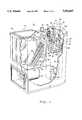
- FIG. 1is a partial cutaway, perspective view of a combination water heating and space heating apparatus having a water heating unit and a space heating unit, according to the present invention
- FIG. 2is a partial cutaway, elevation view of the apparatus
- FIG. 3is a partial cutaway, exploded view of an interior part of the water heating unit
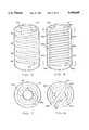
- FIG. 4is a top plan view of the water heating unit
- FIG. 5is an elevation view of the interior of the water heating unit with a single helically wound tubular heat exchanger
- FIG. 6is an elevation view of the interior of the water heating unit with a double helically wound tubular heat exchanger
- FIG. 7is a sectional view taken along the line 7--7 of FIG. 6;
- FIG. 8is a sectional view taken along the line 8--8 of FIG. 6;
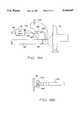
- FIG. 9Ais a schematic of a gas-air metering device for supplying a combustible gas-air mixture to the water heating unit;
- FIG. 9Bis a detailed view of a portion of the gas-air metering device of FIG. 9A;
- FIG. 10is a block diagram of the electronic control system of the apparatus.
- FIGS. 11-16are flow diagrams illustrating the control of the water heating unit.
- FIG. 17is a flow diagram illustrating the control of the space heating unit.
- a combination water heating and space heating apparatus 10includes a water heating unit 12 and a space heating unit 14.
- units 12 and 14are depicted in a side-by-side configuration with unit 14 positioned for "up flow” operation (i.e., air is blown upwardly through unit 14).
- unit 14may be positioned for "down flow” (i.e., air is blown downwardly through unit 14) or "side flow” (i.e., unit 14 is positioned horizontally for horizontal air flow) operation.
- unit 14may be spaced apart from unit 12, with water flow piping and electrical connections 15 therebetween, as shown in FIG. 2.
- unit 12may be used to supply hot water to a plurality of space heating units 14 (e.g., zoned space heating with one unit 14 operatively associated with each zone). Further, unit 12 may be used to supply hot water to one or more low temperature baseboard heaters, to one or more radiant floor heaters, or to any combination of space heating units 14, baseboard heaters and radiant floor heaters. Further, unit 12 is operable as a stand-alone water heater.
- space heating units 14e.g., zoned space heating with one unit 14 operatively associated with each zone.
- unit 12may be used to supply hot water to one or more low temperature baseboard heaters, to one or more radiant floor heaters, or to any combination of space heating units 14, baseboard heaters and radiant floor heaters. Further, unit 12 is operable as a stand-alone water heater.
- Unit 12is housed in a heavy gauge steel casing 16.
- Unit 14is housed in a steel cabinet 18, the interior of which is insulated with fiberglass insulation in the conventional manner.
- Unit 14is adapted to engage a supply air duct (not shown) of a space conditioning system, such that the interior of cabinet 18 forms part of the supply air duct.
- Cabinet 18is adapted to receive an air conditioning evaporator coil, electronic air cleaner, humidifier and other conventional accessories.
- unit 14is an air handler releasably coupled to unit 12 by means of conventional releasable pipe couplings 19 and 21 (FIG. 4).
- wateris circulated between a water storage tank 20 inside casing 16 and a heat exchanger coil 22 inside cabinet 18.
- Coil 22is a conventional hydronic coil with a plurality of tubes 30 and fins 31 extending between tubes 30.
- a water circulation pump 24is also housed in cabinet 18 for drawing water from tank 20 through a supply conduit 26 into a supply manifold 28. Heated water is then distributed from supply manifold 28 through tubes 30 as in a conventional hydronic heat exchanger coil.
- the heated watermakes multiple passes through tubes 30 and exits coil 22 into a return manifold 32 on the suction side of pump 24.
- Pump 24returns the water to tank 20 through a return conduit 34 on the discharge side of pump 24.
- Both supply conduit 26 and return conduit 34are in communication with the interior of tank 20 via respective dip tubes 36 and 38 (FIGS. 3 and 4).
- Supply conduit 26is coupled to dip tube 36 and return conduit 34 is coupled to dip tube 38 by conventional releasable pipe couplings 19 and 21, thereby releasably coupling unit 14 to unit 12.
- a multiple speed blower 25is housed in cabinet 18 for blowing supply air over coil 22, whereby the air is heated by the hot water flowing through tubes 30 and by fins 31.
- Coil 22is located in one compartment of cabinet 18 and blower 25 is located in an adjacent compartment of cabinet 18, as in a conventional air handler.
- tank 20is an insulated stainless steel water storage tank having a capacity of approximately thirty gallons of hot water at adjustable temperatures ranging from 110° F. to 170° F.
- a liquid impervious housing 40is suspended within tank 20 from a top part thereof, such that housing 40 is substantially immersed in the water stored in tank 20.
- Housing 40defines a substantially sealed combustion chamber 42 inside housing 40.
- a gas burner 44having the form of a hollow cylinder closed at its lower end but open at its upper end, is located in combustion chamber 42. Burner 44 extends downwardly through a central circular opening 46 in housing 40 into combustion chamber 42.
- An annular flange 48extends radially outward from the upper end of burner 44.
- Housing 40has an annular top flange 50 external to tank 20.
- Flange 50is engageable with flange 48 to close off opening 46 after burner 44 has been inserted into combustion chamber 42 through opening 46.
- a gasket(not shown) is interposed between flanges 48 and 50 to provide a fluid-tight seal.
- Burner 44has a plurality of small apertures 52 for establishing fluid communication between the interior of burner 44 and combustion chamber 42 surrounding burner 44. Burner 44 is selectively removable from and insertable into combustion chamber 42 through opening 46.
- Housing 40has a substantially cylindrical main body portion 53 and a frusto-conical top section comprising a first frusto-conical section 54 above main body portion 53 and a second frusto-conical section 56 above first frusto-conical section 54.
- First frusto-conical section 54extends upwardly from main body portion 53 and is tapered inwardly at an angle of approximately 36° relative to a horizontal axis.
- Second frusto-conical section 56extends upwardly from first frusto-conical section 54 and is tapered slightly inwardly at an angle of approximately 11° relative to a vertical axis. Second frusto-conical section 56 protrudes through a central circular opening in tank 20 and terminates at flange 50.
- Flange 50extends radially inward from second frusto-conical section 56 and includes a downwardly extending inner-lip 60. Second frusto-conical section 56 is in contact with tank 20 to close off the tank opening. Second frusto-conical section 56 is secured to tank 20 (e.g., by welding) to suspend housing 40 within tank 20.
- substantially the entire housing 40is immersed in water, except for part of second frusto-conical section 56 and flange 50, which represent an insubstantial portion of the surface area of housing 40. Water is therefore able to come into direct contact with first and second frusto-conical sections 54 and 56) and main body portion 53 of housing 40, thereby enhancing the heat transfer between the products of combustion inside combustion chamber 42 and the surrounding water.
- Tank 20has conventional drain valves 43 on a bottom portion of tank 20 for draining tank 20, as shown in FIG. 4.
- Dip tubes 36 and 38are configured to provide a circumferential flow of water around housing 40, as indicated by arrows 62. Dip tubes 36 and 38 are located in proximity to housing 40 and include a plurality of holes 64. Holes 64 of dip tube 38 discharge the water returning from coil 22 through return conduit 34 horizontally into tank 20. By the same token, the water to be supplied to coil 22 is drawn horizontally through holes 64 into dip tube 36 and upwardly into supply conduit 26. The respective locations of dip tubes 36 and 38 with respect to housing 40 are such dip tubes 36 and 38 cooperate with pump 24 to provide the circumferential flow of water, indicated by arrows 62. Because combustion chamber 42 is located in the top part of tank 20, the hottest water is generated in the top part of tank 20. Therefore, the circumferential flow of water around housing 40 picks up heat not only from the surrounding hot water, but also by direct contact with housing 40 as the water flows around housing 40, thereby further heating the water supplied to coil 22 for space heating.
- Another water circulation pump 66is located on top of tank 20 for circulating water within tank 20.
- the suction side of pump 66is in fluid communication with the hot water in the top part of tank 20 by means of a suction line 68, which includes a check valve to ensure one-way flow.
- the discharge side of pump 66is in fluid communication with a cold water fill line 70 by means of a discharge line 72.
- Cold water fill line 70which is in fluid communication with a source of potable water (not shown), penetrates through the top of tank 20 and extends vertically downward through the interior of tank 20 to a position at or near the bottom thereof.
- Pump 66is therefore operable to draw hot water from the top part of tank 20 and discharge the water into cold water fill line 70.
- the hot water introduced into fill line 70 by pump 66mixes with the incoming cold water and is discharged from fill line 70 at or near the bottom of tank 20, thereby circulating water within tank 20 and providing relatively uniform heating of the water within tank 20 from top to bottom.
- a combustion air blower 74is mounted on top of tank 20 for providing a combustible gas-air mixture to burner 44.
- a combustion air intake duct 76in fluid communication with an external air supply (not shown) supplies combustion air to blower 74 and an automatic gas valve 78 coupled to a gas fuel source (not shown) supplies gas fuel to blower 74. Gas and air are supplied to the suction side of blower 74.
- a temperature/pressure relief valve 80is also mounted on top of tank 20 for relieving excessive temperature and pressure therein in the event of other system component failures.
- a hot water supply line 81penetrates upwardly through the top of tank 20 for supplying hot water for use other than for space heating (e.g., for domestic use).
- Tube 82is preferably a 13/4" outside diameter stainless steel tube having a plurality of turns. As shown in FIG. 5, tube 82 terminates at a 21/4" diameter stainless steel manifold 84 at or near the bottom of tank 20. Tube 82 is in heat exchange relationship with the surrounding water in tank 20 for transferring heat to the water.
- One end of manifold 84protrudes outwardly from a bottom part of tank 20 for exhausting products of combustion therefrom and a condensate trap 86 extends downwardly from manifold 84 external to tank 20 (FIG. 1) for draining condensed products of combustion.
- a flue 88extends upwardly from manifold 84 between casing 16 and tank 20 and penetrates the top part of casing 16. Flue 88 is adapted for engagement with an external flue (not shown) for exhausting non-condensed products of combustion upwardly through the top of casing 16 into a conventional exhaust system (not shown).
- the turns of tube 82are spaced at sufficient intervals along a central axis of tube 82 to accommodate another helical tube of the same diameter and configuration with each turn of the other helical tube interposed between successive turns of tube 82, as shown in FIG. 6.
- the spacing interval between successive turns of tube 82should be slightly greater than the diameter of tube 82 to allow water to flow between adjacent turns when two helical tubes 82 are configured as shown in FIG. 6.
- successive turns of tube 82should be spaced so that there is an approximately 41/16" spacing between the center of each turn and the center of the next successive turn of tube 82. This spacing provides sufficient room for a 13/4" diameter turn of a second helical tube to be interposed between successive turns of tube 82 and allow an approximately 1/4" space between adjacent turns in the dual tube configuration shown in FIG. 6.
- tubes 82a and 82bare provided for exhausting products of combustion from combustion chamber 42.
- Tubes 82a and 82bare each preferably 13/4" diameter stainless steel tubes.
- Tubes 82a and 82bextend outwardly from main body portion 53 of housing 40 at diametrically opposed positions thereon and downwardly within tank 20.
- Each tube 82a, 82bhas a plurality of turns.
- Each of the turns of tube 82ais interposed between successive turns of tube 82b and is concentric therewith.
- each of the turns of tube 82bis interposed between successive turns of tube 82a and is concentric therewith.
- Tubes 82a and 82btherefore form a tightly packed heat exchanger configuration, as can be best seen in FIG. 6.
- Tubes 82a and 82bare in heat exchange relationship with the surrounding water in tank 20 for transferring heat to the water.
- Tubes 82a and 82bterminate adjacent respective opposed ends of a manifold 85. By the time the products of combustion reach manifold 85, at least some of the products of combustion have been condensed, thereby further enhancing the efficiency of apparatus 10.
- One end of manifold 85protrudes outwardly through tank 20 for exhausting products of combustion therefrom.
- each 13/4" tube 82a, 82bcan be formed using a conventional helical tube forming machine. After tubes 82a, 82b are individually formed, they are positioned to form the double helical configuration.
- combustion airis supplied to a combustion air conduit 94 through air intake duct 76.
- An air flow restricting devicesuch as an orifice 96, is located in conduit 94.
- a gas supply conduit 98is in fluid communication between gas valve 78 and conduit 94 downstream of orifice 96.
- a gas flow restricting devicesuch as an orifice 100, is located in gas supply conduit 98.
- a pressure switch sensor 102measures the differential pressure across orifice 96.
- the differential pressure across orifice 96is proportional to the air flow rate through orifice 96.
- Gas valve 78is preferably a pneumatically actuated gas metering valve (e.g., a pneumatically actuated gas metering valve of the type sold by White Rodgers, Honeywell or Robert Shaw) for controlling the flow rate of gas through conduit 98 in a predetermined proportion to the flow rate of air through orifice 96.
- a pneumatically actuated gas metering valvee.g., a pneumatically actuated gas metering valve of the type sold by White Rodgers, Honeywell or Robert Shaw
- gas valve 78receives a biasing signal via line 104.
- the biasing signal supplied to gas valve 78 through line 104would represent the air pressure in conduit 94 upstream of orifice 96.
- gas valve 78determines the flow rate of air in conduit 94 and meters the flow of gas to conduit 98 accordingly.
- Line 104is coupled to gas valve 78 by means of a standard hexagonal coupling fitting 106.
- fitting 106has an aperture 108 on the order of 0.035" in diameter.
- Aperture 108communicates between the interior of line 104 and the external ambient environment to adjust the biasing signal. Because conduit 94 is on the suction side of combustion air blower 74, the pressure in conduit 94 is negative with respect to the external atmospheric pressure when blower 74 is operating.
- Aperture 108functions as a rate averaging orifice to provide an adjusted biasing signal indicating an air pressure intermediate the actual air pressure in conduit 94 upstream of orifice 96 and atmospheric pressure.
- Control module 110includes a microcontroller of the ST6225 type, sold by SGS-Thomson Microelectronics and control module 112 includes a microcontroller of the PIC16CR54 type, sold by Microchip.
- Control module 110receives information from a plurality of sensors, including a flame sensor 114 (preferably a rectification-type flame sensor), pressure switch sensor 102, a temperature limit switch sensor 116, a temperature setpoint sensor 118 (preferably a potentiometer) for indicating a water temperature setpoint and a tank water temperature sensor 120 (preferably a thermistor) for sensing water temperature.
- the water temperature setpointcorresponds to the desired water temperature and may be changed by adjusting sensor 118.
- control module 110controls combustion air blower (CAB) 74, gas valve 78, water circulating pump 66 and a spark igniter 122.
- Control module 112receives input from an indoor thermostat 124, which indicates a space air temperature setpoint, and controls water circulation pump 24 and supply air blower 25 accordingly.
- the space air temperature setpointcorresponds to the desired air temperature of the space.
- Control module 110communicates with control module 112. Specifically, control module 112 sends an electrical signal to control module 110, as indicated by arrow 126, in response to a demand for space heating received by control module 112 from thermostat 124.
- Control module 110sends an electrical signal to control module 112, as indicated by arrow 128, in response to an indication from thermistor 120 that the tank water temperature has fallen below a minimum temperature threshold (e.g., 20° F. below the water temperature setpoint).
- a minimum temperature thresholde.g. 20° F. below the water temperature setpoint.
- a constant minimum temperaturemay be used as the reference for determining whether a low temperature condition occurs.
- the "low temperature" signal sent by control module 110 to control module 112causes control module 112 to inhibit operation of pump 24 and blower 25 unless blower 25 is set for "continuous fan" operation, as will be described in greater detail hereinafter.
- FIGS. 11-16depict the control of water heating unit 12 and FIG. 17 depicts the control of space heating unit 14.
- thermistor 120indicates that the tank water temperature has fallen below the temperature setpoint by a predetermined temperature increment (e.g., 3° F.)
- a call (demand) for tank heatis indicated.
- control module 110checks temperature limit switch sensor 116, which should be in a closed position. If it is not, a sensor failure is indicated and a Postpurge routine is initiated to purge combustion chamber 42 (FIG. 3) for thirty seconds. The Postpurge routine will be described in greater detail hereinafter.
- a demand routine(FIG. 15) is run to determine if there is a call for tank heating. If there is not a call for tank heat, retry and recycle counters (not shown) are cleared and control module 110 waits for a call for tank heat. If there is a call for tank heat, control module 110 checks pressure switch sensor 102, which should be open. If sensor 102 remains closed for thirty seconds, a sensor failure is indicated and the Postpurge routine is implemented. If sensor 102 is open, combustion air blower 74 is turned on at high speed to blow combustion air into combustion chamber 42. If within two minutes after blower 74 is activated at high speed, pressure switch sensor 102 is still open, a sensor failure is indicated and control module 110 will initiate the Postpurge routine.
- control module 110initiates a Prepurge routine to purge combustion chamber 42 for ten seconds prior to introducing a combustible gas-air mixture into burner 44 (FIG. 3). If a flame is detected by flame sensor 114 after Prepurge, the Prepurge routine is repeated until the flame is no longer detected. Upon completion of Prepurge, a Trial For Ignition routine is initiated, as depicted in FIG. 12. After completion of the Prepurge, blower 74 is turned off for three seconds. At the end of three seconds, gas valve 78 is opened and spark igniter 122 is activated to ignite the combustible gas-air mixture in burner 44.
- Blower 74remains off for two seconds after gas valve 78 is opened and spark igniter 122 is activated. By turning off combustion air blower 74 during ignition, a gas-rich mixture is provided, which is ignitable at a low fire ("soft light") condition, thereby decreasing the noise and ignition pressures typically associated with direct ignition of a combustible gas-air mixture. At the end of the two second time delay, blower 74 is activated at high speed. After five more seconds, control module 110 deactivates spark igniter 122. If a flame is detected by flame sensor 114, control module 110 initiates a Flame Stabilization routine, as depicted in FIG. 13.
- gas valve 78is closed and the retry counter, which keeps track of the number of attempts to establish a flame, is incremented.
- An Interpurge routineis implemented to purge combustion chamber 42 for ten seconds after each unsuccessful attempt to establish a flame (up to a maximum of four times during any one call for tank heat cycle) before control module 110 makes another attempt to light burner 44. After the fifth try, if the flame is still not detected, the Postpurge routine is implemented.
- a Flame Stabilization routineis initiated for a period of ten seconds, whereby the stability of the flame is monitored.
- Circulation pump 66is activated in response to a flame being sensed by flame sensor 114. If there is a flame failure for a full two seconds during the ten second Flame Stabilization period, gas valve 78 is closed and pump 66 is deactivated.
- the Interpurge routineis initiated to purge combustion chamber 42 for ten seconds after each unsuccessful attempt to establish a flame (up to a maximum of four tries during any one call for tank heat cycle) before control module 110 makes another attempt to light burner 44. After the fifth try, if the flame is still not detected, the Postpurge routine is initiated.
- a low temperature signal(Lo Temp) is generated. This low temperature signal is transmitted from control module 110 to control module 112, as indicated by arrow 128 in FIG. 10, to prevent supply air blower 25 from operating. As long as a low temperature signal is present, circulation pump 66 remains on, irrespective of whether there is a call for space heating. If a low temperature signal is not present, a call for space heating signal transmitted from control module 112 to control module 110, as indicated by arrow 126, causes control module 110 to turn off pump 66.
- pump 66may remain in operation even if there is a call for space heating, depending on the capacity of unit 12 and the extent of the call for space heating (e.g., where there is a call for space heating in only one of a plurality of space heating zones).
- pump 66When pump 66 is off, the hottest water in the vicinity of combustion chamber housing 40 (FIG. 3) is available for space heating. At the end of the ten second Flame Stabilization period, the retry counter is cleared.
- a Burner Supervision routineis initiated, as shown in FIG. 14.
- the demand routine(FIG. 15) is run to determine if there is still a call for tank heat. If there is no call for tank heat, gas valve 78 is closed and circulation pump 66 is turned off.
- the Postpurge routineis implemented to purge combustion chamber 42 and the recycle counter, which keeps track of the number of attempts to re-establish the flame after a flame failure, is cleared. If there is still a call for tank heat, control module 110 continues the Burner Supervision routine to monitor the operation of burner 44.
- flame sensor 114indicates a flame failure for a full 0.6 second during Burner Supervision routine
- gas valve 78is closed, pump 66 is turned off and the recycle counter is incremented.
- the Interpurge routineis initiated after each flame failure (up to a maximum of four flame failures during any one call for tank heat cycle) to purge combustion chamber 42 for ten seconds before attempting to re-establish the flame. After the fifth flame failure, the Postpurge routine is initiated.
- control module 110determines whether a low temperature condition is present (i.e., tank water temperature 20° F. or more below temperature setpoint). If a low temperature condition is present, pump 66 will remain on, irrespective of whether there is a call for space heat. If a low temperature condition is not present, a call for space heat will result in pump 66 being turned off, as previously described. Until the tank water temperature is within 10° F. of the temperature setpoint, blower 74 will remain on at high speed. When the water temperature is within 10° F. of the temperature setpoint, blower 74 is reduced to low speed.
- a low temperature conditioni.e., tank water temperature 20° F. or more below temperature setpoint.
- Control module 110determines if thermistor 120 is operable. If a thermistor failure condition is indicated, the Postpurge routine is initiated. If thermistor 120 is operable, the temperature setpoint from sensor 118 is loaded into the control program. If there is a call for space heat, the increased demand for hot water is anticipated by raising the previously loaded temperature setpoint by 5° F. As such, there is usually a call for tank heat in response to a call for space heat.
- a call for tank heatmay not occur (at least not immediately) in response to a call for space heat.
- the low temperature signalis generated. Once generated, the low temperature signal remains on until the tank water temperature is within 15° F. of the temperature setpoint.
- the demand routinegenerates a call for tank heat signal until the tank temperature is within 5° F. of the temperature setpoint.
- the Postpurge routineis initiated in response to the absence of a call for tank heat signal.
- control module 110continually monitors pressure switch sensor 102 and temperature limit switch sensor 116. If temperature limit switch sensor is detected in an open position, a high temperature limit condition is indicated. In response thereto, control module 110 shuts off the gas supply and initiates the Postpurge routine, which is depicted in FIG. 16. Similarly, if pressure switch sensor 102 is detected in an open position when blower 74 is on, a low combustion air pressure condition is indicated. In response thereto, control module 110 shuts off the gas supply and initiates the Postpurge routine.
- control module 110initiates a Watchguard routine for approximately one hour after the Postpurge routine, as shown in FIG. 16.
- the Watchguard routinethe entire water heating unit 12 is deactivated. If the Postpurge routine is initiated in response to the absence of a call for tank heat (e.g., satisfaction of a tank heating demand), the Watchguard routine is not implemented, as shown in FIG. 16.
- Control module 12resets a six-hour timer (not shown) in response to a demand for space heating.
- the six-hour timeris used to ensure that water is circulated at least once every six hours between tank 20 (FIG. 1) and coil 22 (FIG. 1).
- blower 25 and related accessoriese.g., humidifier, dehumidifier, electrostatic air cleaner, etc.
- blower 25is set for continuous fan operation at thermostat 124, in which case blower 25 is turned on at continuous fan speed and the related accessories are turned on.
- Pump 24does not circulate water between tank 20 and heat exchanger 22 in response to a low temperature signal from control module 110 so that the hot water in tank is available for use other than for space heating (e.g., domestic use).
- control module 112sends a demand for space heating signal, which occurs when the space air temperature falls below the thermostat setpoint by a predetermined temperature increment (e.g., 3° F.), to control module 110 and activates pump 24 to circulate water between tank 20 and coil 22.
- a predetermined temperature incremente.g. 3° F.
- control module 110deactivates pump 66 in response to a demand for space heating signal if a low temperature signal is not present.
- Control module 112waits a selectable delay period (e.g., 15, 30, 45 or 60 seconds) before activating blower 25. This selectable delay period allows time for the hot water to reach coil 22 before activating blower 25, to prevent an initial surge of cold air through the supply air duct.
- blower 25is turned on at heating speed (which is typically higher than the continuous fan speed) and the related accessories are turned on.
- heating speedwhich is typically higher than the continuous fan speed
- pump 24is deactivated and control module 112 signals control module 110 that the space heating demand has been satisfied.
- Blower 25remains on for an additional fixed delay period (e.g., 30 seconds) to extract residual heat from coil 22. At the end of the fixed delay period, blower 25 and the accessories are deactivated.
- cabinet 18(FIG. 1) is adapted to receive an air conditioning coil (not shown) so that cabinet 18 forms part of a supply air duct for cooled air as well as heated air.
- blower 25is turned on at cooling speed (which is typically higher than heating speed) and the related accessories are also turned on. When the cooling demand is satisfied, blower 25 and the accessories are turned off. Water is not circulated between tank 20 and coil 22 when a cooling demand is present.
- pump 24is operated for thirty seconds to circulate water between tank 20 and coil 22. This periodic circulation prevents water in coil 22 and in conduits 26 and 34 (FIGS. 1 and 2) from becoming stagnant, thereby inhibiting the growth of bacteria and algae in coil 22 and in conduits 26 and 34.
- the six hour timeris reset to begin counting a new six-hour period.
- the combined water heating and space heating apparatusprovides energy-efficient space heating and water heating.
- the space heating and water heatingare coordinately controlled to give priority to the potable hot water supply over space heating if sufficient hot water is not available to satisfy both demands.
- the apparatusis programmed to try to prevent this condition from occurring by anticipating the hot water needed to satisfy a space heating demand.
- the tank temperature setpointis raised by a predetermined amount (e.g., 5° F.) such that a demand for space heating usually triggers operation of water heating unit 12 to impart additional heat to the water in tank 20, even if the water was already at the original temperature setpoint when the space heating demand occurred. Hot water shortages should, therefore, not occur, except under extreme conditions.
Landscapes
- Engineering & Computer Science (AREA)
- Physics & Mathematics (AREA)
- General Engineering & Computer Science (AREA)
- Chemical & Material Sciences (AREA)
- Combustion & Propulsion (AREA)
- Mechanical Engineering (AREA)
- Thermal Sciences (AREA)
- Fluid Mechanics (AREA)
- Computer Hardware Design (AREA)
- Steam Or Hot-Water Central Heating Systems (AREA)
- Electric Stoves And Ranges (AREA)
- Resistance Heating (AREA)
- Heat-Pump Type And Storage Water Heaters (AREA)
Abstract
Description
Claims (19)
Priority Applications (7)
| Application Number | Priority Date | Filing Date | Title |
|---|---|---|---|
| US08/296,112US5544645A (en) | 1994-08-25 | 1994-08-25 | Combination water heating and space heating apparatus |
| NZ291547ANZ291547A (en) | 1994-08-25 | 1995-08-23 | Gas fired combined water heater and space heating system |
| EP95929322AEP0776445A4 (en) | 1994-08-25 | 1995-08-23 | Combination water heating and space heating apparatus |
| JP8508072AJPH10505404A (en) | 1994-08-25 | 1995-08-23 | Combined water heater / heating system |
| CA002197174ACA2197174A1 (en) | 1994-08-25 | 1995-08-23 | Combination water heating and space heating apparatus |
| AU32712/95AAU698716B2 (en) | 1994-08-25 | 1995-08-23 | Combination water heating and space heating apparatus |
| PCT/US1995/009348WO1996006309A2 (en) | 1994-08-25 | 1995-08-23 | Combination water heating and space heating apparatus |
Applications Claiming Priority (1)
| Application Number | Priority Date | Filing Date | Title |
|---|---|---|---|
| US08/296,112US5544645A (en) | 1994-08-25 | 1994-08-25 | Combination water heating and space heating apparatus |
Publications (1)
| Publication Number | Publication Date |
|---|---|
| US5544645Atrue US5544645A (en) | 1996-08-13 |
Family
ID=23140667
Family Applications (1)
| Application Number | Title | Priority Date | Filing Date |
|---|---|---|---|
| US08/296,112Expired - LifetimeUS5544645A (en) | 1994-08-25 | 1994-08-25 | Combination water heating and space heating apparatus |
Country Status (7)
| Country | Link |
|---|---|
| US (1) | US5544645A (en) |
| EP (1) | EP0776445A4 (en) |
| JP (1) | JPH10505404A (en) |
| AU (1) | AU698716B2 (en) |
| CA (1) | CA2197174A1 (en) |
| NZ (1) | NZ291547A (en) |
| WO (1) | WO1996006309A2 (en) |
Cited By (53)
| Publication number | Priority date | Publication date | Assignee | Title |
|---|---|---|---|---|
| US5772113A (en)* | 1994-11-10 | 1998-06-30 | Advanced Mechanical Technology, Inc. | Two-pipe heat pump system with isolated tank coil for domestic hot water |
| US5816199A (en)* | 1997-01-23 | 1998-10-06 | Aga Technologies, Inc. | High efficiency water heater |
| US5918805A (en)* | 1998-01-14 | 1999-07-06 | Yankee Scientific, Inc. | Self-powered space heating system |
| US5984198A (en)* | 1997-06-09 | 1999-11-16 | Lennox Manufacturing Inc. | Heat pump apparatus for heating liquid |
| US6032868A (en)* | 1996-03-19 | 2000-03-07 | Dimarco; Giovanni | Combined hot water and space heater |
| US6053418A (en)* | 1998-01-14 | 2000-04-25 | Yankee Scientific, Inc. | Small-scale cogeneration system for producing heat and electrical power |
| US6234400B1 (en) | 1998-01-14 | 2001-05-22 | Yankee Scientific, Inc. | Small scale cogeneration system for producing heat and electrical power |
| US6553946B1 (en) | 2000-06-09 | 2003-04-29 | Roberrshaw Controls Company | Multi-function water heater control device |
| US6598397B2 (en) | 2001-08-10 | 2003-07-29 | Energetix Micropower Limited | Integrated micro combined heat and power system |
| US6681723B1 (en) | 2003-02-12 | 2004-01-27 | Marvin Amendt | Hot water heater |
| US20040142295A1 (en)* | 2003-01-22 | 2004-07-22 | Calcutt Boats Ltd. | Narrowboat auxiliary heater and method of controlling same |
| US20040226296A1 (en)* | 2001-08-10 | 2004-11-18 | Hanna William Thompson | Integrated micro combined heat and power system |
| US6857578B2 (en) | 2003-05-15 | 2005-02-22 | Lennox Manufacturing Inc. | Combination water heating and space heating apparatus and control therefor |
| US20050156051A1 (en)* | 2002-12-24 | 2005-07-21 | Lipidex Corporation, A Massachusetts Corporation | Space heating and cooling |
| US20050224591A1 (en)* | 2004-04-13 | 2005-10-13 | Jason Wolfson | Damper control in space heating and cooling |
| US20050258263A1 (en)* | 2004-05-18 | 2005-11-24 | International Thermal Investments Ltd. | Potable water heater |
| US20060009736A1 (en)* | 2004-07-07 | 2006-01-12 | Brijesh Gill | Portable fluid warming system |
| US20060053821A1 (en)* | 2004-09-16 | 2006-03-16 | Taras Michael F | Refrigerant heat pump with reheat circuit |
| WO2007075169A1 (en)* | 2005-12-28 | 2007-07-05 | The Board Of Regents Of The University Of Texas System | Portable fluid warming system |
| US20070248921A1 (en)* | 2006-04-19 | 2007-10-25 | Rinnai Corporation | Combustion apparatus |
| US20070284454A1 (en)* | 2006-06-08 | 2007-12-13 | Cuppetilli Robert D | Secondary heating system |
| WO2008010631A1 (en)* | 2006-07-18 | 2008-01-24 | Energy Nature Technology Co., Ltd. | Hot water supplyer for hot water circulation mat |
| US20080021393A1 (en)* | 2004-07-07 | 2008-01-24 | Brijesh Gill | Portable Fluid Warming System |
| US20080089795A1 (en)* | 2006-10-16 | 2008-04-17 | Hitachi Industrial Equipment Systems Co., Ltd. | Water-Injected Compressor |
| US20080264490A1 (en)* | 2007-04-24 | 2008-10-30 | Rinnai America Corporation, A Corporation Of Georgia | Methods and apparatus for heating air with hot water |
| US20090000611A1 (en)* | 2005-01-24 | 2009-01-01 | Kaiser Stewart R | Solar and heat pump powered electric forced hot air hydronic furnace |
| US20090078783A1 (en)* | 2006-06-08 | 2009-03-26 | Cuppetilli Robert D | Secondary heating and cooling system |
| US20090078784A1 (en)* | 2006-02-20 | 2009-03-26 | Alessandro Fiumidinisi | Combined heating/hot water system for a vehicle |
| US20100170658A1 (en)* | 2009-01-02 | 2010-07-08 | Electro Industries, Inc. | Dual-Pressure Dual-Compartment Fluid Tank |
| US20100198411A1 (en)* | 2009-01-30 | 2010-08-05 | Jason Wolfson | Ventilation system |
| US20110101119A1 (en)* | 2008-02-13 | 2011-05-05 | Dynatronic Gmbh | Heating system producing electricity |
| US20110259322A1 (en)* | 2010-01-25 | 2011-10-27 | Htp, Inc. | Method and system for controlling efficiency of heating system |
| US20120055419A1 (en)* | 2010-09-08 | 2012-03-08 | General Electric Company | Demand management for water heaters |
| CN103759327A (en)* | 2014-01-03 | 2014-04-30 | 林治森 | Finned radiator or radiator with humidifying function |
| US20150354834A1 (en)* | 2014-06-09 | 2015-12-10 | Nordyne Llc | Thaw cycle in condensing style gas furnaces |
| US9322568B2 (en) | 2010-10-07 | 2016-04-26 | Field Controls, Llc | Whole house ventilation system |
| US20160209052A1 (en)* | 2013-08-27 | 2016-07-21 | Kyungdong Navien Co., Ltd. | Method for determining whether hot water is used during heating of an air handler system |
| US20160273798A1 (en)* | 2015-03-20 | 2016-09-22 | Dan R. Guay | Heating assembly |
| US9494320B2 (en) | 2013-01-11 | 2016-11-15 | Honeywell International Inc. | Method and system for starting an intermittent flame-powered pilot combustion system |
| WO2017027857A1 (en)* | 2015-08-12 | 2017-02-16 | Sarkis Sr Anthony Michael | Hot water heating system and related methods |
| US10208954B2 (en) | 2013-01-11 | 2019-02-19 | Ademco Inc. | Method and system for controlling an ignition sequence for an intermittent flame-powered pilot combustion system |
| CN113324282A (en)* | 2021-06-04 | 2021-08-31 | 何林 | Constant-temperature-keeping circulation heating energy-saving water heating device and using method thereof |
| US11125439B2 (en) | 2018-03-27 | 2021-09-21 | Scp Holdings, An Assumed Business Name Of Nitride Igniters, Llc | Hot surface igniters for cooktops |
| US20210325050A1 (en)* | 2020-04-20 | 2021-10-21 | Emerson Electric Co. | Spark ignition module and methods |
| US11226135B2 (en) | 2018-05-15 | 2022-01-18 | Gas Technology Institute | Control apparatus and method for combination space and water heating |
| US11236930B2 (en) | 2018-05-01 | 2022-02-01 | Ademco Inc. | Method and system for controlling an intermittent pilot water heater system |
| US11293668B2 (en)* | 2016-10-26 | 2022-04-05 | National Machine Group | Hot water tank with thermal mixing valve |
| US20220214049A1 (en)* | 2021-01-06 | 2022-07-07 | Gradient Thermal Inc. | Combination space and hot water heater |
| US11656000B2 (en) | 2019-08-14 | 2023-05-23 | Ademco Inc. | Burner control system |
| US20230258368A1 (en)* | 2017-12-21 | 2023-08-17 | Rheem Manufacturing Company | Water Heater Operation Monitoring and Notification |
| US11739982B2 (en) | 2019-08-14 | 2023-08-29 | Ademco Inc. | Control system for an intermittent pilot water heater |
| CN116781849A (en)* | 2023-07-28 | 2023-09-19 | 上海大帜信息技术有限公司 | Handheld terminal of law enforcement appearance with heating function |
| US12422157B2 (en) | 2017-06-16 | 2025-09-23 | Copeland Comfort Control Lp | Wirelessly configuring climate control system controls |
Families Citing this family (4)
| Publication number | Priority date | Publication date | Assignee | Title |
|---|---|---|---|---|
| WO2007062493A1 (en)* | 2005-11-29 | 2007-06-07 | Macpherson Engineering Inc. | Heat source for radiant heating system |
| ITPN20110055A1 (en)* | 2011-07-22 | 2013-01-23 | Mcz Group S P A | HEATING EQUIPMENT |
| JP6136848B2 (en)* | 2013-10-22 | 2017-05-31 | 株式会社デンソー | Hot water storage water heater |
| JP2020118440A (en)* | 2019-01-23 | 2020-08-06 | 株式会社デンソーウェーブ | Gas water heater |
Citations (16)
| Publication number | Priority date | Publication date | Assignee | Title |
|---|---|---|---|---|
| US2787318A (en)* | 1949-11-04 | 1957-04-02 | John J Wolfersperger | Burner with tangential air admission and restricted throat |
| US3741710A (en)* | 1971-12-20 | 1973-06-26 | L Nelson | Combustion control valve means and system |
| US4158386A (en)* | 1975-07-03 | 1979-06-19 | Raytheon Company | Self-pumping water boiler system |
| US4178907A (en)* | 1978-07-27 | 1979-12-18 | Sweat James R Jr | Unified hot water and forced air heating system |
| US4222350A (en)* | 1978-06-26 | 1980-09-16 | Boston Gas Products, Inc. | Efficient heating and domestic hot water apparatus |
| US4241720A (en)* | 1979-01-26 | 1980-12-30 | Kitchen John A | Pulse combustion apparatus |
| US4336820A (en)* | 1978-08-31 | 1982-06-29 | Parker-Hannifin Corporation | Metering device for adding one fluid to another |
| US4371111A (en)* | 1980-06-24 | 1983-02-01 | Pernosky Richard J | Home heating system employing water heater as heating source |
| US4398502A (en)* | 1980-07-28 | 1983-08-16 | Park Ki D | Water heater with up-down flow flue |
| US4449484A (en)* | 1981-11-30 | 1984-05-22 | Tokyo Shibaura Denki Kabushiki Kaisha | Hot water supply system |
| US4492185A (en)* | 1981-10-05 | 1985-01-08 | Alzeta Corporation | High efficiency, reduced emissions water heater |
| US4541410A (en)* | 1983-07-20 | 1985-09-17 | Columbia Gas System Service Corporation | Apparatus and method for burning a combustible gas, and a heat exchanger for use in this apparatus |
| US4584987A (en)* | 1982-11-03 | 1986-04-29 | Remo Rotili | Heating system using wood as the principal source of energy |
| US4641631A (en)* | 1983-07-20 | 1987-02-10 | Columbia Gas System Service Corporation | Apparatus and method for burning a combustible gas, and a heat exchanger for use in this apparatus |
| US4766883A (en)* | 1986-02-26 | 1988-08-30 | Mor-Flo Industries, Inc. | Forced draft controlled mixture heating system using a closed combustion chamber |
| US5022352A (en)* | 1990-05-31 | 1991-06-11 | Mor-Flo Industries, Inc. | Burner for forced draft controlled mixture heating system using a closed combustion chamber |
- 1994
- 1994-08-25USUS08/296,112patent/US5544645A/ennot_activeExpired - Lifetime
- 1995
- 1995-08-23JPJP8508072Apatent/JPH10505404A/enactivePending
- 1995-08-23EPEP95929322Apatent/EP0776445A4/ennot_activeWithdrawn
- 1995-08-23NZNZ291547Apatent/NZ291547A/enunknown
- 1995-08-23WOPCT/US1995/009348patent/WO1996006309A2/ennot_activeApplication Discontinuation
- 1995-08-23AUAU32712/95Apatent/AU698716B2/ennot_activeCeased
- 1995-08-23CACA002197174Apatent/CA2197174A1/ennot_activeAbandoned
Patent Citations (16)
| Publication number | Priority date | Publication date | Assignee | Title |
|---|---|---|---|---|
| US2787318A (en)* | 1949-11-04 | 1957-04-02 | John J Wolfersperger | Burner with tangential air admission and restricted throat |
| US3741710A (en)* | 1971-12-20 | 1973-06-26 | L Nelson | Combustion control valve means and system |
| US4158386A (en)* | 1975-07-03 | 1979-06-19 | Raytheon Company | Self-pumping water boiler system |
| US4222350A (en)* | 1978-06-26 | 1980-09-16 | Boston Gas Products, Inc. | Efficient heating and domestic hot water apparatus |
| US4178907A (en)* | 1978-07-27 | 1979-12-18 | Sweat James R Jr | Unified hot water and forced air heating system |
| US4336820A (en)* | 1978-08-31 | 1982-06-29 | Parker-Hannifin Corporation | Metering device for adding one fluid to another |
| US4241720A (en)* | 1979-01-26 | 1980-12-30 | Kitchen John A | Pulse combustion apparatus |
| US4371111A (en)* | 1980-06-24 | 1983-02-01 | Pernosky Richard J | Home heating system employing water heater as heating source |
| US4398502A (en)* | 1980-07-28 | 1983-08-16 | Park Ki D | Water heater with up-down flow flue |
| US4492185A (en)* | 1981-10-05 | 1985-01-08 | Alzeta Corporation | High efficiency, reduced emissions water heater |
| US4449484A (en)* | 1981-11-30 | 1984-05-22 | Tokyo Shibaura Denki Kabushiki Kaisha | Hot water supply system |
| US4584987A (en)* | 1982-11-03 | 1986-04-29 | Remo Rotili | Heating system using wood as the principal source of energy |
| US4541410A (en)* | 1983-07-20 | 1985-09-17 | Columbia Gas System Service Corporation | Apparatus and method for burning a combustible gas, and a heat exchanger for use in this apparatus |
| US4641631A (en)* | 1983-07-20 | 1987-02-10 | Columbia Gas System Service Corporation | Apparatus and method for burning a combustible gas, and a heat exchanger for use in this apparatus |
| US4766883A (en)* | 1986-02-26 | 1988-08-30 | Mor-Flo Industries, Inc. | Forced draft controlled mixture heating system using a closed combustion chamber |
| US5022352A (en)* | 1990-05-31 | 1991-06-11 | Mor-Flo Industries, Inc. | Burner for forced draft controlled mixture heating system using a closed combustion chamber |
Non-Patent Citations (2)
| Title |
|---|
| "The Application of Combustion Principles to Domestic Gas Burner Design"; H. R. N. Jones, MA, PhD, CEng, MIGasE, British Gas Teaching Fellow, University of Cambridge; 1989. |
| The Application of Combustion Principles to Domestic Gas Burner Design ; H. R. N. Jones, MA, PhD, CEng, MIGasE, British Gas Teaching Fellow, University of Cambridge; 1989.* |
Cited By (97)
| Publication number | Priority date | Publication date | Assignee | Title |
|---|---|---|---|---|
| US5772113A (en)* | 1994-11-10 | 1998-06-30 | Advanced Mechanical Technology, Inc. | Two-pipe heat pump system with isolated tank coil for domestic hot water |
| US6032868A (en)* | 1996-03-19 | 2000-03-07 | Dimarco; Giovanni | Combined hot water and space heater |
| US5816199A (en)* | 1997-01-23 | 1998-10-06 | Aga Technologies, Inc. | High efficiency water heater |
| US5984198A (en)* | 1997-06-09 | 1999-11-16 | Lennox Manufacturing Inc. | Heat pump apparatus for heating liquid |
| US5918805A (en)* | 1998-01-14 | 1999-07-06 | Yankee Scientific, Inc. | Self-powered space heating system |
| US6053418A (en)* | 1998-01-14 | 2000-04-25 | Yankee Scientific, Inc. | Small-scale cogeneration system for producing heat and electrical power |
| US6234400B1 (en) | 1998-01-14 | 2001-05-22 | Yankee Scientific, Inc. | Small scale cogeneration system for producing heat and electrical power |
| US6553946B1 (en) | 2000-06-09 | 2003-04-29 | Roberrshaw Controls Company | Multi-function water heater control device |
| US6598397B2 (en) | 2001-08-10 | 2003-07-29 | Energetix Micropower Limited | Integrated micro combined heat and power system |
| US20040083732A1 (en)* | 2001-08-10 | 2004-05-06 | Hanna William Thompson | Integrated micro combined heat and power system |
| US20040226296A1 (en)* | 2001-08-10 | 2004-11-18 | Hanna William Thompson | Integrated micro combined heat and power system |
| US20050156051A1 (en)* | 2002-12-24 | 2005-07-21 | Lipidex Corporation, A Massachusetts Corporation | Space heating and cooling |
| US7225995B2 (en)* | 2002-12-24 | 2007-06-05 | Lipidex Corporation | Space heating and cooling |
| US20040142295A1 (en)* | 2003-01-22 | 2004-07-22 | Calcutt Boats Ltd. | Narrowboat auxiliary heater and method of controlling same |
| US6883467B2 (en)* | 2003-01-22 | 2005-04-26 | International Thermal Investments Ltd. | Narrowboat auxiliary heater and method of controlling same |
| US6681723B1 (en) | 2003-02-12 | 2004-01-27 | Marvin Amendt | Hot water heater |
| US6857578B2 (en) | 2003-05-15 | 2005-02-22 | Lennox Manufacturing Inc. | Combination water heating and space heating apparatus and control therefor |
| US20070045436A1 (en)* | 2004-04-13 | 2007-03-01 | Jason Wolfson | Damper control in space heating and cooling |
| US20070045438A1 (en)* | 2004-04-13 | 2007-03-01 | Jason Wolfson | Damper control in space heating and cooling |
| US20050224591A1 (en)* | 2004-04-13 | 2005-10-13 | Jason Wolfson | Damper control in space heating and cooling |
| US20100044448A1 (en)* | 2004-04-13 | 2010-02-25 | Jason Wolfson | Ventilation System and Method |
| US20070045434A1 (en)* | 2004-04-13 | 2007-03-01 | Jason Wolfson | Damper control in space heating and cooling |
| US20070045440A1 (en)* | 2004-04-13 | 2007-03-01 | Jason Wolfson | Damper control in space heating and cooling |
| US20070045437A1 (en)* | 2004-04-13 | 2007-03-01 | Jason Wolfson | Damper control in space heating and cooling |
| US8185244B2 (en)* | 2004-04-13 | 2012-05-22 | Tuckernuck Technologies Llc | Ventilation system and method |
| US20070045435A1 (en)* | 2004-04-13 | 2007-03-01 | Jason Wolfson | Damper control in space heating and cooling |
| US20070045439A1 (en)* | 2004-04-13 | 2007-03-01 | Jason Wolfson | Damper control in space heating and cooling |
| US20070051821A1 (en)* | 2004-04-13 | 2007-03-08 | Jason Wolfson | Damper control in space heating and cooling |
| US20070051822A1 (en)* | 2004-04-13 | 2007-03-08 | Jason Wolfson | Damper control in space heating and cooling |
| US7258280B2 (en) | 2004-04-13 | 2007-08-21 | Tuckernuck Technologies Llc | Damper control in space heating and cooling |
| US8118239B2 (en)* | 2004-05-18 | 2012-02-21 | International Thermal Investments Ltd. | Potable water heater |
| US20050258263A1 (en)* | 2004-05-18 | 2005-11-24 | International Thermal Investments Ltd. | Potable water heater |
| US20080021393A1 (en)* | 2004-07-07 | 2008-01-24 | Brijesh Gill | Portable Fluid Warming System |
| US8753382B2 (en) | 2004-07-07 | 2014-06-17 | The Board Of Regents Of The University Of Texas Systems | Portable fluid warming system |
| US7261557B2 (en) | 2004-07-07 | 2007-08-28 | The Board Of Regents Of The University Of Texas System | Portable fluid warming system |
| US20060009736A1 (en)* | 2004-07-07 | 2006-01-12 | Brijesh Gill | Portable fluid warming system |
| US20110184501A1 (en)* | 2004-07-07 | 2011-07-28 | Brijesh Gill | Portable Fluid Warming System |
| US7891974B2 (en) | 2004-07-07 | 2011-02-22 | The Board Of Regents Of The University Of Texas System | Portable fluid warming system |
| US20060053821A1 (en)* | 2004-09-16 | 2006-03-16 | Taras Michael F | Refrigerant heat pump with reheat circuit |
| US20090000611A1 (en)* | 2005-01-24 | 2009-01-01 | Kaiser Stewart R | Solar and heat pump powered electric forced hot air hydronic furnace |
| WO2007075169A1 (en)* | 2005-12-28 | 2007-07-05 | The Board Of Regents Of The University Of Texas System | Portable fluid warming system |
| US8807447B2 (en)* | 2006-02-20 | 2014-08-19 | Webasto SE | Combined heating/hot water system for a vehicle |
| US20090078784A1 (en)* | 2006-02-20 | 2009-03-26 | Alessandro Fiumidinisi | Combined heating/hot water system for a vehicle |
| US7824177B2 (en)* | 2006-04-19 | 2010-11-02 | Rinnai Corporation | Combustion apparatus |
| US20070248921A1 (en)* | 2006-04-19 | 2007-10-25 | Rinnai Corporation | Combustion apparatus |
| US7628337B2 (en)* | 2006-06-08 | 2009-12-08 | Cuppetilli Robert D | Secondary heating system |
| US20090078783A1 (en)* | 2006-06-08 | 2009-03-26 | Cuppetilli Robert D | Secondary heating and cooling system |
| US20070284454A1 (en)* | 2006-06-08 | 2007-12-13 | Cuppetilli Robert D | Secondary heating system |
| WO2008010631A1 (en)* | 2006-07-18 | 2008-01-24 | Energy Nature Technology Co., Ltd. | Hot water supplyer for hot water circulation mat |
| US8459957B2 (en)* | 2006-10-16 | 2013-06-11 | Hitachi Industrial Equipment Systems, Co., Ltd. | Water-injected compressor |
| US20080089795A1 (en)* | 2006-10-16 | 2008-04-17 | Hitachi Industrial Equipment Systems Co., Ltd. | Water-Injected Compressor |
| AU2008201830B2 (en)* | 2007-04-24 | 2013-07-25 | Rinnai America Corporation | Methods and apparatus for heating air with hot water |
| US8662404B2 (en) | 2007-04-24 | 2014-03-04 | Rinnai America Corporation | Methods and apparatus for heating air with hot water |
| US20080264490A1 (en)* | 2007-04-24 | 2008-10-30 | Rinnai America Corporation, A Corporation Of Georgia | Methods and apparatus for heating air with hot water |
| US8353463B2 (en)* | 2007-04-24 | 2013-01-15 | Rinnai America Corporation | Methods and apparatus for heating air with hot water |
| US9810449B2 (en) | 2007-04-24 | 2017-11-07 | Rinnai America Corporation | Methods and apparatus for heating air with hot water |
| WO2009018025A1 (en)* | 2007-08-01 | 2009-02-05 | The Board Of Regents Of The University Of Texas System | Portable fluid warming system |
| US20110101119A1 (en)* | 2008-02-13 | 2011-05-05 | Dynatronic Gmbh | Heating system producing electricity |
| US20100170658A1 (en)* | 2009-01-02 | 2010-07-08 | Electro Industries, Inc. | Dual-Pressure Dual-Compartment Fluid Tank |
| US20100198411A1 (en)* | 2009-01-30 | 2010-08-05 | Jason Wolfson | Ventilation system |
| US20110259322A1 (en)* | 2010-01-25 | 2011-10-27 | Htp, Inc. | Method and system for controlling efficiency of heating system |
| US20120055419A1 (en)* | 2010-09-08 | 2012-03-08 | General Electric Company | Demand management for water heaters |
| US8720388B2 (en)* | 2010-09-08 | 2014-05-13 | General Electric Company | Demand management for water heaters |
| US9322568B2 (en) | 2010-10-07 | 2016-04-26 | Field Controls, Llc | Whole house ventilation system |
| US11719436B2 (en) | 2013-01-11 | 2023-08-08 | Ademco Inc. | Method and system for controlling an ignition sequence for an intermittent flame-powered pilot combustion system |
| US11268695B2 (en) | 2013-01-11 | 2022-03-08 | Ademco Inc. | Method and system for starting an intermittent flame-powered pilot combustion system |
| US10429068B2 (en) | 2013-01-11 | 2019-10-01 | Ademco Inc. | Method and system for starting an intermittent flame-powered pilot combustion system |
| US10208954B2 (en) | 2013-01-11 | 2019-02-19 | Ademco Inc. | Method and system for controlling an ignition sequence for an intermittent flame-powered pilot combustion system |
| US9494320B2 (en) | 2013-01-11 | 2016-11-15 | Honeywell International Inc. | Method and system for starting an intermittent flame-powered pilot combustion system |
| US10113751B2 (en)* | 2013-08-27 | 2018-10-30 | Kyungdong Navien Co., Ltd. | Method for determining whether hot water is used during heating of an air handler system |
| US20160209052A1 (en)* | 2013-08-27 | 2016-07-21 | Kyungdong Navien Co., Ltd. | Method for determining whether hot water is used during heating of an air handler system |
| CN103759327A (en)* | 2014-01-03 | 2014-04-30 | 林治森 | Finned radiator or radiator with humidifying function |
| US20150354834A1 (en)* | 2014-06-09 | 2015-12-10 | Nordyne Llc | Thaw cycle in condensing style gas furnaces |
| US20160273798A1 (en)* | 2015-03-20 | 2016-09-22 | Dan R. Guay | Heating assembly |
| WO2017027857A1 (en)* | 2015-08-12 | 2017-02-16 | Sarkis Sr Anthony Michael | Hot water heating system and related methods |
| US10288314B2 (en)* | 2015-08-12 | 2019-05-14 | Anthony Michael SARKIS, SR. | Hot water heating system and related methods |
| US11105533B2 (en) | 2015-08-12 | 2021-08-31 | Anthony Michael SARKIS, SR. | Hot water heating systems and related methods |
| US20180195763A1 (en)* | 2015-08-12 | 2018-07-12 | Anthony Michael SARKIS, SR. | Hot water heating system and related methods |
| US11293668B2 (en)* | 2016-10-26 | 2022-04-05 | National Machine Group | Hot water tank with thermal mixing valve |
| US11747047B2 (en) | 2016-10-26 | 2023-09-05 | National Machine Group | Hot water tank with thermal mixing valve |
| US12422157B2 (en) | 2017-06-16 | 2025-09-23 | Copeland Comfort Control Lp | Wirelessly configuring climate control system controls |
| US20230258368A1 (en)* | 2017-12-21 | 2023-08-17 | Rheem Manufacturing Company | Water Heater Operation Monitoring and Notification |
| US12203684B2 (en)* | 2017-12-21 | 2025-01-21 | Rheem Manufacturing Company | Water heater operation monitoring and notification |
| US11125439B2 (en) | 2018-03-27 | 2021-09-21 | Scp Holdings, An Assumed Business Name Of Nitride Igniters, Llc | Hot surface igniters for cooktops |
| US11493208B2 (en) | 2018-03-27 | 2022-11-08 | Scp Holdings, An Assumed Business Name Of Nitride Igniters, Llc | Hot surface igniters for cooktops |
| US11788728B2 (en) | 2018-03-27 | 2023-10-17 | Scp R&D, Llc | Hot surface igniters for cooktops |
| US11719467B2 (en) | 2018-05-01 | 2023-08-08 | Ademco Inc. | Method and system for controlling an intermittent pilot water heater system |
| US11236930B2 (en) | 2018-05-01 | 2022-02-01 | Ademco Inc. | Method and system for controlling an intermittent pilot water heater system |
| US11226135B2 (en) | 2018-05-15 | 2022-01-18 | Gas Technology Institute | Control apparatus and method for combination space and water heating |
| US11656000B2 (en) | 2019-08-14 | 2023-05-23 | Ademco Inc. | Burner control system |
| US11739982B2 (en) | 2019-08-14 | 2023-08-29 | Ademco Inc. | Control system for an intermittent pilot water heater |
| US20210325050A1 (en)* | 2020-04-20 | 2021-10-21 | Emerson Electric Co. | Spark ignition module and methods |
| US12339039B2 (en) | 2020-04-20 | 2025-06-24 | Copeland Comfort Control Lp | Spark ignition module and methods |
| US12050030B2 (en)* | 2020-04-20 | 2024-07-30 | Copeland Comfort Control Lp | Spark ignition module and methods |
| US20220214049A1 (en)* | 2021-01-06 | 2022-07-07 | Gradient Thermal Inc. | Combination space and hot water heater |
| CN113324282A (en)* | 2021-06-04 | 2021-08-31 | 何林 | Constant-temperature-keeping circulation heating energy-saving water heating device and using method thereof |
| CN116781849A (en)* | 2023-07-28 | 2023-09-19 | 上海大帜信息技术有限公司 | Handheld terminal of law enforcement appearance with heating function |
Also Published As
| Publication number | Publication date |
|---|---|
| WO1996006309A3 (en) | 1996-04-11 |
| AU3271295A (en) | 1996-03-14 |
| WO1996006309A2 (en) | 1996-02-29 |
| JPH10505404A (en) | 1998-05-26 |
| EP0776445A2 (en) | 1997-06-04 |
| NZ291547A (en) | 1998-10-28 |
| CA2197174A1 (en) | 1996-02-29 |
| AU698716B2 (en) | 1998-11-05 |
| EP0776445A4 (en) | 1999-03-03 |
Similar Documents
| Publication | Publication Date | Title |
|---|---|---|
| US5544645A (en) | Combination water heating and space heating apparatus | |
| US6109339A (en) | Heating system | |
| DK171187B1 (en) | Gas heater for room heating | |
| CA2273533C (en) | Power vent water heater with electronic control system | |
| US4925093A (en) | Forced draft direct vent system for a water heater | |
| US9243848B2 (en) | Water heating system | |
| AU2006222728B2 (en) | Instantaneous fuel-fired water heater with low temperature plastic vent structure | |
| US20080216770A1 (en) | Water heating system | |
| US5950573A (en) | Power vented water heater with air inlet | |
| JPS633672A (en) | Adaptive control of motor | |
| US4738394A (en) | Integral liquid-backed gas-fired space heating and hot water system | |
| US4678116A (en) | Water heater | |
| AU2010241269A1 (en) | A furnace header box having blocked condensation protection, a furnace including the header box and a blocked condensation protection system | |
| CA2367218C (en) | Fuel-fired water heater with flammable vapour sensor and associated induced flow tube | |
| US6202935B1 (en) | Combined potable water heater and hydronic heating system | |
| CA2580168C (en) | Ducted secondary air fuel-fired water heater ldo detection | |
| US5664555A (en) | Wall heater with improved heat exchanger | |
| CN207162699U (en) | A kind of warm bath dual-purpose stove of full pre-mix condensing combustion gas | |
| KR101464690B1 (en) | Small inverter electric boiler | |
| RU2715877C1 (en) | Method of heating boiler operation in heating system | |
| KR100279831B1 (en) | Flue for Condensing Gas Boiler | |
| KR100782999B1 (en) | Air conditioner for livestock | |
| KR200326523Y1 (en) | Air volume control damper of boiler | |
| JP2567503B2 (en) | Fluid heating device | |
| KR20020007858A (en) | Apparatus for controlling purge heating of boiler and the method thereof |
Legal Events
| Date | Code | Title | Description |
|---|---|---|---|
| AS | Assignment | Owner name:LENNOX INDUSTRIES INC. Free format text:ASSIGNMENT OF ASSIGNORS INTEREST;ASSIGNORS:ARMIJO, DAVID L.;BAKER, TONY R.;BEILFUSS, ROBERT C.;AND OTHERS;REEL/FRAME:007153/0692;SIGNING DATES FROM 19940816 TO 19940823 | |
| AS | Assignment | Owner name:LENNOX MANUFACTURING INC., IOWA Free format text:ASSIGNMENT OF ASSIGNORS INTEREST;ASSIGNOR:LENNOX INDUSTRIES, INC.;REEL/FRAME:008955/0381 Effective date:19980101 | |
| FEPP | Fee payment procedure | Free format text:PAYOR NUMBER ASSIGNED (ORIGINAL EVENT CODE: ASPN); ENTITY STATUS OF PATENT OWNER: LARGE ENTITY | |
| FPAY | Fee payment | Year of fee payment:4 | |
| FPAY | Fee payment | Year of fee payment:8 | |
| REMI | Maintenance fee reminder mailed | ||
| REIN | Reinstatement after maintenance fee payment confirmed | ||
| FP | Lapsed due to failure to pay maintenance fee | Effective date:20080813 | |
| FEPP | Fee payment procedure | Free format text:PETITION RELATED TO MAINTENANCE FEES FILED (ORIGINAL EVENT CODE: PMFP); ENTITY STATUS OF PATENT OWNER: LARGE ENTITY Free format text:PETITION RELATED TO MAINTENANCE FEES GRANTED (ORIGINAL EVENT CODE: PMFG); ENTITY STATUS OF PATENT OWNER: LARGE ENTITY | |
| PRDP | Patent reinstated due to the acceptance of a late maintenance fee | Effective date:20090514 | |
| FPAY | Fee payment | Year of fee payment:12 | |
| SULP | Surcharge for late payment | ||
| STCF | Information on status: patent grant | Free format text:PATENTED CASE |