US5544250A - Noise suppression system and method therefor - Google Patents
Noise suppression system and method thereforDownload PDFInfo
- Publication number
- US5544250A US5544250AUS08/276,737US27673794AUS5544250AUS 5544250 AUS5544250 AUS 5544250AUS 27673794 AUS27673794 AUS 27673794AUS 5544250 AUS5544250 AUS 5544250A
- Authority
- US
- United States
- Prior art keywords
- snr
- noise
- signal
- estimates
- estimate
- Prior art date
- Legal status (The legal status is an assumption and is not a legal conclusion. Google has not performed a legal analysis and makes no representation as to the accuracy of the status listed.)
- Expired - Lifetime
Links
- 230000001629suppressionEffects0.000titleclaimsabstractdescription84
- 238000000034methodMethods0.000titleclaimsabstractdescription43
- 238000010586diagramMethods0.000description12
- 230000005236sound signalEffects0.000description11
- 230000003595spectral effectEffects0.000description10
- 238000004891communicationMethods0.000description9
- 230000008569processEffects0.000description9
- 230000001413cellular effectEffects0.000description6
- 238000009499grossingMethods0.000description5
- 230000004044responseEffects0.000description5
- 238000012545processingMethods0.000description4
- 238000001914filtrationMethods0.000description3
- 230000002238attenuated effectEffects0.000description2
- 230000008859changeEffects0.000description2
- 230000000593degrading effectEffects0.000description2
- 230000004048modificationEffects0.000description2
- 238000012986modificationMethods0.000description2
- 230000009467reductionEffects0.000description2
- 230000005534acoustic noiseEffects0.000description1
- 238000013459approachMethods0.000description1
- 230000005540biological transmissionEffects0.000description1
- 230000006835compressionEffects0.000description1
- 238000007906compressionMethods0.000description1
- 238000001514detection methodMethods0.000description1
- 230000001627detrimental effectEffects0.000description1
- 230000007613environmental effectEffects0.000description1
- 230000036039immunityEffects0.000description1
- 230000007246mechanismEffects0.000description1
- 239000003607modifierSubstances0.000description1
- 238000011045prefiltrationMethods0.000description1
- 230000009290primary effectEffects0.000description1
- 238000005070samplingMethods0.000description1
Images


Classifications
- H—ELECTRICITY
- H04—ELECTRIC COMMUNICATION TECHNIQUE
- H04R—LOUDSPEAKERS, MICROPHONES, GRAMOPHONE PICK-UPS OR LIKE ACOUSTIC ELECTROMECHANICAL TRANSDUCERS; DEAF-AID SETS; PUBLIC ADDRESS SYSTEMS
- H04R3/00—Circuits for transducers, loudspeakers or microphones
- H—ELECTRICITY
- H03—ELECTRONIC CIRCUITRY
- H03G—CONTROL OF AMPLIFICATION
- H03G3/00—Gain control in amplifiers or frequency changers
Definitions
- the present inventionrelates generally to audio signal processing and, more particularly, to a noise suppression system and method therefor used when processing audio signals.
- Audio signal processorstypically process audio signals to modify characteristics of the audio signals. Typical applications of audio signal processors include filtering, speech compression, echo cancelling, noise suppression and energy estimation. Audio signal processors are frequently used in communication systems for processing speech. Audio signal processors advantageously provides improved audio quality, and efficient transmission and storage of speech.
- Acoustic noise suppression in a speech communication systemgenerally serves the purpose of improving the overall quality of the desired audio signal by filtering environmental background noise from the desired speech signal.
- This speech enhancement processis particularly necessary in environments having abnormally high levels of ambient background noise, such as an aircraft, a moving vehicle, or a noisy factory.
- One noise suppression techniqueis a spectral subtraction--or a spectral gain modification--technique.
- the audio input signalis divided into individual spectral bands by a bank of bandpass filters, and particular spectral bands are attenuated according to their noise energy content.
- a spectral subtraction noise suppression prefilterutilizes an estimate of the background noise power spectral density to generate a signal-to-noise ratio (SNR) of the speech in each channel, which, in turn, is used to compute a gain factor for each individual channel. The gain factor is used as the attenuation for that particular spectral band.
- the channelsare then attenuated and recombined to produce the noise-suppressed output waveform.
- noise suppression techniquesexhibit significant performance limitations.
- One example of such an applicationis the vehicle speakerphone option to a cellular mobile radio telephone system, which provides hands-free operation for the automobile driver.
- the mobile hands-free microphoneis typically located at a greater distance from the user, such as being mounted overhead on the visor.
- the more distant microphonedelivers a much poorer signal-to-noise ratio to the land-end party due to road and wind noise conditions.
- the received speech at the land-endis usually intelligible, continuous exposure to such background noise levels often increases listener fatigue.
- the noise flutter performancewas further improved by the technique of smoothing the noise suppression gain factors for each individual channel on a per-sample basis instead of on a per-frame basis.
- this techniquedid not appreciate that the primary source of the channel gain discontinuities is the inherent fluctuation of background noise in each channel from one frame to the next. In known spectral subtraction systems, even a 2 dB SNR variation would create a few dB of gain variation, which is then heard as an annoying background noise flutter.
- U.S. Pat. No. 4,811,404addressed the noise flutter problem with an improved noise suppression system which performs speech quality enhancement upon the speech-plus-noise signal available at the input to generate a clean speech signal at the output by spectral gain modification.
- the improvementsincluded the addition of a signal-to-noise ratio (SNR) threshold mechanism to reduce background noise flutter by offsetting the gain rise of the gain tables until a certain SNR threshold is reached, the use of a voice metric calculator to produce a more accurate background noise estimates via performing the update decision based on the overall voice-like characteristics in the channels and the time interval since the last update, and the use of a channel SNR modifier to provide immunity to narrow band noise bursts through modification of the SNR estimates based on the voice metric calculation and the channel energies.
- SNRsignal-to-noise ratio
- energy estimatorsestimate the energy in a signal.
- the energy estimate of the signalis typically used in audio signal processors.
- Typical applications of the energy estimate in signal processorsincludes signal detection, noise estimation, and signal to noise ratio estimation.
- a common problem in estimating the energy of a noise signalis that the variance of the energy estimate from one estimate to another is large.
- FIG. Iillustrates a block diagram of a communication unit in accordance with the present invention.
- FIG. 2illustrates a block diagram of a noise suppression system of the communication unit of FIG. 1 in accordance with the present invention.
- FIG: 3illustrates a plurality of frequency bands used by a signal divider of FIG. 2 to divide an input signal into a plurality of divided signals corresponding to the plurality of frequency bands in accordance with the present invention.
- FIG. 4illustrates a block diagram of an energy estimator of the noise suppression system of FIG. 2 in accordance with the present invention.
- FIG. 5illustrates a plurality of signals represented in the block diagram of the energy estimator of FIG. 4 in accordance with the present invention.
- FIG. 6illustrates a process flow diagram performed by the energy estimator of FIG. 4 in accordance with the present invention.
- FIG. 7illustrates a graph of a signal gain produced by a signal gain calculator of the noise suppression system of FIG. 2 responsive to a signal to noise ratio (SNR) estimate produced by a SNR estimator of the noise suppression system FIG. 2 in accordance with the present invention.
- SNRsignal to noise ratio
- FIG. 8illustrates a process flow diagram performed by the noise suppression system of FIG. 2 in accordance with the present invention.
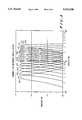
- FIG. 9illustrates a graph showing the response time of an estimated SNR estimate and a noise energy estimate to a positive unit step function in an energy estimate of FIG. 2, in accordance with the present invention.
- the noise suppression systemcomprises a signal estimator, a signal gain calculator and a signal level adjuster.
- the signal estimatoroperatively coupled to receive an input signal, produces a noise energy estimate of the input signal and a signal to noise ratio (SNR) estimate of the input signal.
- SNRsignal to noise ratio
- the signal gain calculatoroperatively coupled to the signal estimator, calculates a gain value for the input signal according to a first function responsive to the noise energy estimate and the SNR estimate until the SNR estimate reaches a first predetermined SNR threshold, then calculates the gain value for the input signal according to a second function responsive to the noise energy estimate and the SNR estimate until the SNR estimate reaches a second predetermined SNR threshold below the first predetermined SNR threshold.
- the signal level adjusteroperatively coupled to the signal gain calculator, adjusts the level of the input signal responsive to the gain value to produce an adjusted signal having suppressed noise.
- the noise suppression system and method thereforadvantageously improves noise suppression without truncating the tail ends of speech while minimizing noise flutter.
- FIG. 1illustrates a block diagram of a communication unit 100 in accordance with the present invention.
- the communication unit 100generally comprises a microphone 101, an analog to digital (A/D) converter 103, a noise suppression system 105, an audio processor 107, a transmitter 109, and an antenna 111.
- A/Danalog to digital
- the noise suppression system and method thereforwill be described in further detail with reference to FIGS. 2 through 9.
- the microphone 101is coupled to receive an input signal 113, in acoustic form, to produce the input signal in electric form at line 115.
- the A/D converter 103operatively coupled to the microphone 101, converts the input signal in electric form at line 115 to a digital signal at line 116.
- the noise suppression system 105operatively coupled to the A/D converter 103, produces a noise suppressed signal at line 117 responsive to the input signal at line 116.
- the audio signal processor 107operatively coupled to the noise suppression system 105, produces a processed signal at line 119 responsive to the noise suppressed signal at line 117.
- the transmitter 109operatively coupled to the audio processor 107, transmits the processed signal at line 119 to produce a transmitted signal in electric form at line 121.
- the antenna 111operatively coupled to the transmitter 109, converts the transmitted signal in electric form at line 121 to a transmitted signal in electromagnetic form as represented by reference number 123.
- the communication unit 100is preferably a cellular radiotelephone.
- the cellular radiotelephonemay be a digital cellular radiotelephone, such as used in the North American Digital Cellular (NADC) System; the Japan Digital Cellular (JDC) System; or the Group Special Mobile (GSM) System.
- the communication unit 100may be a two-way radio, cordless radiotelephone, or a wireless microphone.
- the input signal 113is preferably speech, producing a signal in the audio band generally known as 300 Hz to 3 KHz. However, noise signals are typically included with the input signal 113 either during speech or between speech.
- the A/D converter 103preferably samples the input signal at line 115 at an 8 kHz rate.
- One frame of the input signal at line 115 sampled at the 8 kHz rateis chosen to include 160 consecutive samples of the input signal at line 115. Therefore, one frame of the input signal at line 115 is produced every 20 msec (160 samples/8000 samples per second).
- the microphone, the audio processor, the transmitter, and the antennaare each well known in the art, and thus no further description will be provided except to facilitate the understanding of the present invention.
- FIG. 2illustrates a block diagram of the noise suppression system 105 of the communication unit 100 of FIG. 1 in accordance with the present invention.
- the noise suppression system 105comprises a signal divider 201, a signal estimator 203, a signal gain calculator 205, a signal level adjustor 207, and a signal combiner 209.
- the signal estimator 203further comprises an energy estimator 223, a noise energy estimator 225, and a signal to noise ratio (SNR) estimator 227.
- SNRsignal to noise ratio
- the signal divider 201will be described in further detail with reference to FIG. 3.
- the energy estimator 223will be described in further detail with reference to FIGS. 4, 5 and 6.
- the signal gain calculator 205will be described in further detail with reference to FIG. 7.
- a method for suppressing noise performed by the noise suppression system 105will be described in further detail with reference to FIG. 8.
- the signal to noise energy estimator 227 and the noise energy estimator 225will be described in further detail with reference to FIG. 9.
- the signal divider 201operatively coupled to receive the input signal at line 116, divides an input signal at line 116 to produce a plurality of divided signals at line 211 corresponding to a plurality of frequency bands.
- the signal estimator 203operatively coupled to the signal divider 201, produces a plurality of noise energy estimates at line 213 corresponding to the plurality of divided signals at line 211 and a plurality of signal to noise ratio (SNR) estimates at line 215 corresponding to the plurality of divided signals at line 211.
- SNRsignal to noise ratio
- the signal gain calculator 205operatively coupled to the signal estimator 203, calculates a plurality of gain values at line 217 corresponding to the plurality of divided signals at line 211 responsive to the plurality of noise energy estimates at line 213, respectively, and the plurality of SNR estimates at line 215, respectively.
- the signal level adjuster 207operatively coupled to the signal gain calculator 205 and the signal divider 201, adjusts the level of the plurality of divided signals at line 211 to produce a plurality of adjusted signals at line 219, respectively, responsive to the plurality of gain values at line 217, respectively.
- the signal combiner 209operatively coupled the signal level adjuster 207, combines the plurality of adjusted signals at line 219 to produce an output signal at line 221 having suppressed noise.
- the noise suppression system 105is preferably performed by a digital signal processor such as a Motorola 56166. However, the noise suppression system 105 may also be implemented in hardware if so desired.
- the noise energy estimator 225operatively coupled to the signal divider 201, produces a plurality of noise energy estimates at line 213 corresponding to the plurality of divided signals at line 211.
- the signal to noise ratio (SNR) estimator 227operatively coupled to the energy estimator 223 and the noise energy estimator 225, produces a plurality of SNR estimates at line 215 corresponding to the plurality of divided signals at line 211 responsive to the plurality of energy estimates at line 229, respectively, and the plurality of noise energy estimates at line 213, respectively.
- a switch 231is operatively coupled between the energy estimator 223 and the noise energy estimator 225.
- the signal to noise ratio estimator 227selectively controls the switch 231 via control line 233 to provide an updated energy estimate at line 229 to the noise energy estimator 225.
- the signal to noise ratio estimator 227For each frame of the input signal at line 115, the signal to noise ratio estimator 227 produces a current SNR estimate (SNR ) at line 215 by dividing the energy of the frame at line 229 by the noise energy estimate of the frame at line 213. Additionally, the signal to noise ratio estimator 227 produces an estimated SNR estimate (SNR) based on the following update equation: ##EQU1##
- SN -- EST -- INCis a variable of the equation.
- the value for SN -- EST -- INCis preferably chosen to be 0.125 dB. This value is chosen to provide optimal tracking of the current SNR estimate (SNR) when the current SNR estimate (SNR) at line 215 is changing quickly or slowly. Other values may alternatively be chosen for other noise suppression systems. Therefore, the estimated SNR estimate (SNR) tracks, i.e., updates or adjusts to, the current SNR estimate (SNR ) at a rate of 6.25 dB per second (0.125 dB/20 msec).
- the signal to noise ratio estimator 223controls the switch responsive to the current SNR estimate (SNR) at line 215, the estimated SNR estimate (SNR), and a predetermined threshold (SN -- EST -- THR) according to the following equation:
- the value of SN -- EST -- THRis preferably 3 dB.
- SNRSNR estimate
- the signal to noise ratio estimator 227assumes that noise is present.
- the signal to noise ratio estimator 227closes the switch 231 so that the noise energy estimate at line 213 will be updated by the noise energy estimator 225.
- the signal to noise ratio estimator 227assumes that the noise floor of the input signal at line 211 has increased. Therefore, the signal to noise ratio estimator 227 will close the switch 231 via line 233 allowing the noise energy estimator 225 to update the noise energy estimate at line 213. Therefore the noise energy estimate at line 213 is resilient to sudden changes in the noise floor of the input signal, i.e., the larger the change in the noise floor of the input signal the longer it takes for the noise energy estimator 225 to update the noise energy estimate at line 213.
- the noise energy estimator 225updates the noise energy noise estimate (N) according to the following equation: ##EQU2##
- RO -- NOISE -- INCis a variable in the equation.
- the value for RO -- NOISE -- INCis preferably 0.125 dB. This value is chosen to provide optimal tracking of the noise floor when the noise energy is changing quickly or slowly. Other values may alternatively be chosen for other noise suppression systems.
- the noise energy estimate (N)tracks, i.e. updates or adjusts to, the noise floor at a rate of 6.25 dB per second (0.125 dB/20 msec.).
- FIG. 9illustrates a graph 900 showing the response time of the estimated SNR estimate (SNR) 903 and the noise energy estimate (N) 905 to a positive unit step function in the energy estimate 901 at line 229, in accordance with the present invention.
- the graph 900 in FIG. 9incorporates the equations used by the signal to noise ratio estimator 227 and the noise energy estimator 225 described above.
- the positive unit step function in the energy estimate 901occurs and the estimated SNR estimate (SNR) 903 begins tracking the energy estimate 901 at the rate of 6.25 dB/sec.
- the level adjuster and the signal combinerare each well known in the art, and thus no further description will be provided except to facilitate the understanding of the present invention.
- FIG. 3illustrates a plurality of frequency bands 301-314 used by a signal divider 201 of FIG. 2 to divide the input signal at line 116 into a plurality of divided signals at line 211 corresponding to the plurality of frequency bands 301-314 in accordance with the present invention.
- the signal divider 201has fourteen frequency bands.
- the signal divider 201is preferably a fourth order normalized lattice filter, as is well known in the art.
- the signal divider 201can be a direct form one or direct form two filter structure, as is well known in the art.
- FIGS. 4 and 5will be described together.
- FIG. 4illustrates a block diagram of the energy estimator 223 of the noise suppression system 105 of FIG. 2 in accordance with the present invention.
- FIG. 5illustrates a plurality of signals represented in the block diagram of the energy estimator of FIG. 4 in accordance with the present invention. The plurality of signals represented in FIG. 5 are magnified to more clearly show the function of the energy estimator 223.
- the energy estimator 223further comprises a decimator 401, a full wave rectifier 403, an averager 405, a logarithmic function determiner 407, and a filter 409.
- the decimator 401operatively coupled to receive the input signal at line 211, decimates the input signal at line 116 to produce a decimated signal at line 411.
- the full wave rectifier 403, operatively coupled to the decimator 401rectifies the decimated signal at line 411 to produce a full wave rectified signal at line 413.
- the averager 405, operatively coupled to the full wave rectifier 403,averages the full wave rectified signal at line 413 over a predetermined time period to produce an averaged signal 415.
- the logarithmic function determiner 407operatively coupled to the averager 405, produces a logarithmic signal at line 417 responsive to applying a logarithmic function to the averaged signal at line 415.
- the filter 409operatively coupled to the logarithmic function determiner 407, filters the logarithmic signal at line 417 to produce the energy estimate signal at line 229.
- the purpose of the decimator 401is to reduce the amount of computation performed by the full wave rectifier 403 and the averager 405 without degrading performance.
- the decimatoris not a necessary element of the energy estimator 223 but an advantageous element.
- the decimator 401removes samples from the frame (as shown in FIG. 5, signals 211 and 411) by selectively processing the input signal at line 211 of the plurality of frequency bands 301-314 according to the Nyquist Sampling Theorem.
- Frequency bands 301-304are decimated by 4, since the frequency content of each frequency band 301-304 is less than 1 kHz.
- Frequency bands 305-308are decimated by 2, since the frequency content of each frequency band 305-308 is less than 2 kHz.
- Frequency bands 309-314are decimated by 1, since the frequency content of each frequency band 309-314 is less than 4 kHz.
- the full wave rectifier 403transforms the input signal having positive and negative values, at line 211 to the full wave rectified signal having only positive values as shown in FIG. 5.
- the averager 405determines the average level of the full wave rectified signal at line 413 over a time duration that is less than the frame rate as shown in FIG. 5.
- the average time durationis one-half the frame rate (10 msec.) to improve the response time of the energy estimate at line 229.
- the logarithmic function determiner 407reduces the dynamic range of the averaged signal at line 415 so that the variance of the averaged signal at line 415 is small.
- the logarithmic function determiner 407is preferably a logarithmic function with a base of ten.
- the energy estimator 223 of the present inventionis advantageous over the energy estimator 220 of U.S. Pat. No. 4,811,404 because it is less complex.
- U.S. Pat. No. 4,811,404uses a full wave rectifier and a double precision low pass filter.
- the reduction in complexity of the energy estimator 223 of the present inventionis accomplished by replacing the double precision low pass filter with the averager 405, the logarithmic function determiner 407 and the filter 409 of the energy estimator 223.
- FIG. 6illustrates a process flow diagram performed by the energy estimator 223 of FIG. 4 in accordance with the present invention.
- the processbegins at step 601.
- the decimator 401decimates the input signal at line 211 to produce the decimated signal at line 411.
- the full-wave rectifier 403rectifies the decimated signal at line 411 to produce a full wave rectified signal at line 413.
- the averager 405averages the full wave rectified signal at line 413 over a predetermined time period to produce an averaged signal at line 415.
- the logarithmic function determiner 407applies a logarithmic function to the averaged signal at line 415 to produce a logarithmic signal at line 417.
- the filter 409filters the logarithmic signal at line 417 to produce an energy estimate of the signal at line 229.
- the processends at step 607.
- FIG. 7illustrates a graph of a signal gain 217 produced by the signal gain calculator 205 of the noise suppression system 105 of FIG. 2 responsive to a signal to noise ratio (SNR) estimate 215 produced by the SNR estimator 227 of the noise suppression system 105 FIG. 2 in accordance with the present invention.
- the signal gain calculator 205operatively coupled to the signal estimator 203, calculates a plurality of constant gain values 701 corresponding to the plurality of divided signals at line 211 according to a first function 703 responsive to the plurality of noise energy estimates at line 213, respectively, and the plurality of SNR estimates at line 215, respectively, until the plurality of SNR estimates at line 215, respectively, reach a first predetermined SNR threshold 705.
- the signal gain calculator 205calculates a plurality of variable gain values 707 corresponding to the plurality of divided signals at line 211 according to a second function 709 responsive to the plurality of noise energy estimates at line 213, respectively, and the plurality of SNR estimates at line 215, respectively, until the plurality of SNR estimates at line 215, respectively, reach a second predetermined SNR threshold 711 below the first predetermined SNR threshold 705. Then the signal gain calculator 205 calculates the plurality of constant gain values 701 according to the first function 703 responsive to the plurality of the noise energy estimates at line 213, respectively, and the plurality of the SNR estimates at line 215, respectively, when the plurality of the SNR estimates at line 215, respectively, reach the second predetermined SNR threshold 711.
- the plurality of constant gain values 701 calculated according to the first function 703are less than the plurality of variable gain values 707 calculated according to the second function 709, respectively, when the plurality of SNR estimates at line 215, respectively, are between the first predetermined SNR threshold 705 and the second predetermined SNR threshold 711.
- the signal gain 217is preferably limited to be less than or equal to zero.
- the signal gain (G) at line 217 of the second function 709 produced by the signal gain calculator 205is preferably represented by the following equation:
- the signal gain (G) at line 217 of the first function 703 produced by the signal gain calculator 205is preferably represented by the following equation:
- the signal gain calculator 205advantageously overcomes the trade-off between voice quality and noise suppression introduced by U.S. Pat. No. 4,811,404.
- the signal gain calculator 205 of the present inventionhas the first function 703, the second function 709, the first threshold 705 and the second threshold 711 to determine the signal gain 217 as shown in FIG. 7.
- the signal gain calculator 240 of U.S. Pat. No. 4,811,404has two functions Group A or Group B and a constant gain, wherein the constant gain is prior to one threshold at 2.25 dB SNR estimate as shown in FIG. 3 of U.S. Pat. No. 4,811,404.
- the constant gain function of the U.S. Pat. No. 4,811,404is represented by reference number 713 in FIG. 7 of the present patent application for reference purposes only.
- the noise suppression system 105 of the present inventionachieves maximum noise suppression, via the first function 703 below the first threshold 705, before the presence of the input signal at line 116 without degrading voice quality after the presence of the input signal at line 116 above the second threshold 711.
- the present inventionhas improved noise suppression than the solution disclosed in U.S. Pat. No. 4,811,404 without truncating the tail ends of speech while minimizing noise flutter. Therefore, in the present invention no compromise is necessary as was necessary in the prior art.
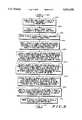
- FIG. 8illustrates a process flow diagram performed by the noise suppression system 105 of FIG. 2 in accordance with the present invention.
- step 802the signal divider 201 divides the input signal at line 116 to produce the plurality of divided signals at line 211 corresponding to the plurality of frequency bands 301-314;
- the energy estimator 223produces the plurality of energy estimates at line 229 corresponding to the plurality of divided signals at line 211;
- the noise energy estimator 224produces the plurality of noise energy estimates at line 213 corresponding to the plurality of divided signals at line 211;
- the SNR estimator 227produces the plurality of SNR estimates at line 215 corresponding to the plurality of divided signals at line 211 responsive to the plurality of energy estimates at line 229, respectively, and the plurality of noise energy estimates at line 213, respectively;
- the signal gain calculator 205calculates the plurality of constant gain values 701 corresponding to the plurality of divided signals at line 211 according to a first function 703 responsive to the plurality of noise energy estimates at line 213, respectively, and the plurality of SNR estimates at line 215, respectively, until the plurality of SNR estimates at line 215, respectively, reach a first predetermined SNR threshold 705.
- the signal gain calculator 205calculates the plurality of variable gain values 707 corresponding to the plurality of divided signals at line 211 according to the second function 709 responsive to the plurality of noise energy estimates at line 215, respectively, and the plurality of SNR estimates at line 215, respectively, until the plurality of SNR estimates at line 215, respectively, reach the second predetermined SNR threshold 711 below the first predetermined SNR threshold 705.
- the signal gain calculator 205calculates the plurality of constant gain values 701 according to the first function 703 responsive to the plurality of the noise energy estimates 213, respectively, and the plurality of the SNR estimates at line 215, respectively, when the plurality of the SNR estimates at line 215, respectively, reach the second predetermined SNR threshold 711.
- the signal level adjustor 207adjusts the level of the plurality of divided signals at line 211 to produce the plurality of adjusted signals at line 219, respectively, responsive to either the plurality of constant gain values 701, respectively, or the plurality of variable gain values 707, respectively.
- the signal combiner 209combines the plurality of adjusted signals at line 219 to produce an output signal at line 221 having suppressed noise.
- the noise suppression system 105 and method thereforadvantageously improves noise suppression without truncating the tail ends of speech while minimizing noise flutter.
- the trade-off between voice quality and noise suppression of the prior artis substantially resolved.
Landscapes
- Physics & Mathematics (AREA)
- Engineering & Computer Science (AREA)
- Acoustics & Sound (AREA)
- Signal Processing (AREA)
- Noise Elimination (AREA)
Abstract
Description
SNR<SNR+SN.sub.-- EST.sub.-- THR
G=N-2*SNR
G=N
Claims (34)
Priority Applications (1)
| Application Number | Priority Date | Filing Date | Title |
|---|---|---|---|
| US08/276,737US5544250A (en) | 1994-07-18 | 1994-07-18 | Noise suppression system and method therefor |
Applications Claiming Priority (1)
| Application Number | Priority Date | Filing Date | Title |
|---|---|---|---|
| US08/276,737US5544250A (en) | 1994-07-18 | 1994-07-18 | Noise suppression system and method therefor |
Publications (1)
| Publication Number | Publication Date |
|---|---|
| US5544250Atrue US5544250A (en) | 1996-08-06 |
Family
ID=23057884
Family Applications (1)
| Application Number | Title | Priority Date | Filing Date |
|---|---|---|---|
| US08/276,737Expired - LifetimeUS5544250A (en) | 1994-07-18 | 1994-07-18 | Noise suppression system and method therefor |
Country Status (1)
| Country | Link |
|---|---|
| US (1) | US5544250A (en) |
Cited By (73)
| Publication number | Priority date | Publication date | Assignee | Title |
|---|---|---|---|---|
| US5666429A (en)* | 1994-07-18 | 1997-09-09 | Motorola, Inc. | Energy estimator and method therefor |
| US5706394A (en)* | 1993-11-30 | 1998-01-06 | At&T | Telecommunications speech signal improvement by reduction of residual noise |
| US5825754A (en)* | 1995-12-28 | 1998-10-20 | Vtel Corporation | Filter and process for reducing noise in audio signals |
| US5839101A (en)* | 1995-12-12 | 1998-11-17 | Nokia Mobile Phones Ltd. | Noise suppressor and method for suppressing background noise in noisy speech, and a mobile station |
| GB2330961A (en)* | 1997-11-04 | 1999-05-05 | Nokia Mobile Phones Ltd | Automatic gain control in mobile phone using speech detection |
| US5933495A (en)* | 1997-02-07 | 1999-08-03 | Texas Instruments Incorporated | Subband acoustic noise suppression |
| US5943429A (en)* | 1995-01-30 | 1999-08-24 | Telefonaktiebolaget Lm Ericsson | Spectral subtraction noise suppression method |
| US6001131A (en)* | 1995-02-24 | 1999-12-14 | Nynex Science & Technology, Inc. | Automatic target noise cancellation for speech enhancement |
| WO1999067774A1 (en)* | 1998-06-22 | 1999-12-29 | Dspc Technologies Ltd. | A noise suppressor having weighted gain smoothing |
| US6032114A (en)* | 1995-02-17 | 2000-02-29 | Sony Corporation | Method and apparatus for noise reduction by filtering based on a maximum signal-to-noise ratio and an estimated noise level |
| US6070137A (en)* | 1998-01-07 | 2000-05-30 | Ericsson Inc. | Integrated frequency-domain voice coding using an adaptive spectral enhancement filter |
| US6104993A (en)* | 1997-02-26 | 2000-08-15 | Motorola, Inc. | Apparatus and method for rate determination in a communication system |
| US6122610A (en)* | 1998-09-23 | 2000-09-19 | Verance Corporation | Noise suppression for low bitrate speech coder |
| US6122384A (en)* | 1997-09-02 | 2000-09-19 | Qualcomm Inc. | Noise suppression system and method |
| WO2001041334A1 (en)* | 1999-12-03 | 2001-06-07 | Motorola Inc. | Method and apparatus for suppressing acoustic background noise in a communication system |
| US20020010583A1 (en)* | 1997-10-31 | 2002-01-24 | Naoto Iwahashi | Feature extraction apparatus and method and pattern recognition apparatus and method |
| US6459914B1 (en)* | 1998-05-27 | 2002-10-01 | Telefonaktiebolaget Lm Ericsson (Publ) | Signal noise reduction by spectral subtraction using spectrum dependent exponential gain function averaging |
| US20020150265A1 (en)* | 1999-09-30 | 2002-10-17 | Hitoshi Matsuzawa | Noise suppressing apparatus |
| US20030004715A1 (en)* | 2000-11-22 | 2003-01-02 | Morgan Grover | Noise filtering utilizing non-gaussian signal statistics |
| US20030028374A1 (en)* | 2001-07-31 | 2003-02-06 | Zlatan Ribic | Method for suppressing noise as well as a method for recognizing voice signals |
| US20030135364A1 (en)* | 2000-03-28 | 2003-07-17 | Ravi Chandran | Spectrally interdependent gain adjustment techniques |
| US6643619B1 (en)* | 1997-10-30 | 2003-11-04 | Klaus Linhard | Method for reducing interference in acoustic signals using an adaptive filtering method involving spectral subtraction |
| US20040002858A1 (en)* | 2002-06-27 | 2004-01-01 | Hagai Attias | Microphone array signal enhancement using mixture models |
| US20040052384A1 (en)* | 2002-09-18 | 2004-03-18 | Ashley James Patrick | Noise suppression |
| US6718301B1 (en)* | 1998-11-11 | 2004-04-06 | Starkey Laboratories, Inc. | System for measuring speech content in sound |
| US6750759B2 (en)* | 1999-12-07 | 2004-06-15 | Nec Infrontia Corporation | Annunciatory signal generating method and device for generating the annunciatory signal |
| US6757395B1 (en)* | 2000-01-12 | 2004-06-29 | Sonic Innovations, Inc. | Noise reduction apparatus and method |
| US20040143433A1 (en)* | 2002-12-05 | 2004-07-22 | Toru Marumoto | Speech communication apparatus |
| US7003099B1 (en)* | 2002-11-15 | 2006-02-21 | Fortmedia, Inc. | Small array microphone for acoustic echo cancellation and noise suppression |
| US7016507B1 (en) | 1997-04-16 | 2006-03-21 | Ami Semiconductor Inc. | Method and apparatus for noise reduction particularly in hearing aids |
| US7020297B2 (en) | 1999-09-21 | 2006-03-28 | Sonic Innovations, Inc. | Subband acoustic feedback cancellation in hearing aids |
| US20060149541A1 (en)* | 2005-01-03 | 2006-07-06 | Aai Corporation | System and method for implementing real-time adaptive threshold triggering in acoustic detection systems |
| US20060184363A1 (en)* | 2005-02-17 | 2006-08-17 | Mccree Alan | Noise suppression |
| US20060265215A1 (en)* | 2005-05-17 | 2006-11-23 | Harman Becker Automotive Systems - Wavemakers, Inc. | Signal processing system for tonal noise robustness |
| US20070136056A1 (en)* | 2005-12-09 | 2007-06-14 | Pratibha Moogi | Noise Pre-Processor for Enhanced Variable Rate Speech Codec |
| US20070154031A1 (en)* | 2006-01-05 | 2007-07-05 | Audience, Inc. | System and method for utilizing inter-microphone level differences for speech enhancement |
| US20070219791A1 (en)* | 2006-03-20 | 2007-09-20 | Yang Gao | Method and system for reducing effects of noise producing artifacts in a voice codec |
| US20070276656A1 (en)* | 2006-05-25 | 2007-11-29 | Audience, Inc. | System and method for processing an audio signal |
| US20080019548A1 (en)* | 2006-01-30 | 2008-01-24 | Audience, Inc. | System and method for utilizing omni-directional microphones for speech enhancement |
| US20090012783A1 (en)* | 2007-07-06 | 2009-01-08 | Audience, Inc. | System and method for adaptive intelligent noise suppression |
| US20090281801A1 (en)* | 2008-05-12 | 2009-11-12 | Broadcom Corporation | Compression for speech intelligibility enhancement |
| US20090287496A1 (en)* | 2008-05-12 | 2009-11-19 | Broadcom Corporation | Loudness enhancement system and method |
| US20090323982A1 (en)* | 2006-01-30 | 2009-12-31 | Ludger Solbach | System and method for providing noise suppression utilizing null processing noise subtraction |
| US20100010808A1 (en)* | 2005-09-02 | 2010-01-14 | Nec Corporation | Method, Apparatus and Computer Program for Suppressing Noise |
| US20100239104A1 (en)* | 2009-03-20 | 2010-09-23 | Harman Becker Automotive Systems Gmbh | System for Attenuating Noise in an Input Signal |
| US7889874B1 (en)* | 1999-11-15 | 2011-02-15 | Nokia Corporation | Noise suppressor |
| US20110178798A1 (en)* | 2010-01-20 | 2011-07-21 | Microsoft Corporation | Adaptive ambient sound suppression and speech tracking |
| US20110211711A1 (en)* | 2010-02-26 | 2011-09-01 | Yamaha Corporation | Factor setting device and noise suppression apparatus |
| CN102215446A (en)* | 2010-04-07 | 2011-10-12 | 奥迪康有限公司 | Method for controlling a binaural hearing aid system and binaural hearing aid system |
| USRE43191E1 (en) | 1995-04-19 | 2012-02-14 | Texas Instruments Incorporated | Adaptive Weiner filtering using line spectral frequencies |
| US8143620B1 (en) | 2007-12-21 | 2012-03-27 | Audience, Inc. | System and method for adaptive classification of audio sources |
| US8180064B1 (en) | 2007-12-21 | 2012-05-15 | Audience, Inc. | System and method for providing voice equalization |
| US8189766B1 (en) | 2007-07-26 | 2012-05-29 | Audience, Inc. | System and method for blind subband acoustic echo cancellation postfiltering |
| US8194882B2 (en) | 2008-02-29 | 2012-06-05 | Audience, Inc. | System and method for providing single microphone noise suppression fallback |
| US8204253B1 (en) | 2008-06-30 | 2012-06-19 | Audience, Inc. | Self calibration of audio device |
| US8204252B1 (en) | 2006-10-10 | 2012-06-19 | Audience, Inc. | System and method for providing close microphone adaptive array processing |
| US8259926B1 (en) | 2007-02-23 | 2012-09-04 | Audience, Inc. | System and method for 2-channel and 3-channel acoustic echo cancellation |
| US8355511B2 (en) | 2008-03-18 | 2013-01-15 | Audience, Inc. | System and method for envelope-based acoustic echo cancellation |
| US8488805B1 (en)* | 2009-12-29 | 2013-07-16 | Audience, Inc. | Providing background audio during telephonic communication |
| US8521530B1 (en) | 2008-06-30 | 2013-08-27 | Audience, Inc. | System and method for enhancing a monaural audio signal |
| US8737654B2 (en) | 2010-04-12 | 2014-05-27 | Starkey Laboratories, Inc. | Methods and apparatus for improved noise reduction for hearing assistance devices |
| US8774423B1 (en) | 2008-06-30 | 2014-07-08 | Audience, Inc. | System and method for controlling adaptivity of signal modification using a phantom coefficient |
| US8849231B1 (en) | 2007-08-08 | 2014-09-30 | Audience, Inc. | System and method for adaptive power control |
| US8934641B2 (en) | 2006-05-25 | 2015-01-13 | Audience, Inc. | Systems and methods for reconstructing decomposed audio signals |
| US8949120B1 (en)* | 2006-05-25 | 2015-02-03 | Audience, Inc. | Adaptive noise cancelation |
| US9008329B1 (en) | 2010-01-26 | 2015-04-14 | Audience, Inc. | Noise reduction using multi-feature cluster tracker |
| US9437180B2 (en) | 2010-01-26 | 2016-09-06 | Knowles Electronics, Llc | Adaptive noise reduction using level cues |
| US9502048B2 (en) | 2010-04-19 | 2016-11-22 | Knowles Electronics, Llc | Adaptively reducing noise to limit speech distortion |
| US9536540B2 (en) | 2013-07-19 | 2017-01-03 | Knowles Electronics, Llc | Speech signal separation and synthesis based on auditory scene analysis and speech modeling |
| US9640194B1 (en) | 2012-10-04 | 2017-05-02 | Knowles Electronics, Llc | Noise suppression for speech processing based on machine-learning mask estimation |
| US9799330B2 (en) | 2014-08-28 | 2017-10-24 | Knowles Electronics, Llc | Multi-sourced noise suppression |
| US20210110840A1 (en)* | 2019-10-11 | 2021-04-15 | Plantronics, Inc. | Hybrid Noise Suppression |
| US11475869B2 (en) | 2021-02-12 | 2022-10-18 | Plantronics, Inc. | Hybrid noise suppression for communication systems |
Citations (8)
| Publication number | Priority date | Publication date | Assignee | Title |
|---|---|---|---|---|
| US4628529A (en)* | 1985-07-01 | 1986-12-09 | Motorola, Inc. | Noise suppression system |
| US4630305A (en)* | 1985-07-01 | 1986-12-16 | Motorola, Inc. | Automatic gain selector for a noise suppression system |
| US4737976A (en)* | 1985-09-03 | 1988-04-12 | Motorola, Inc. | Hands-free control system for a radiotelephone |
| US4809328A (en)* | 1987-02-20 | 1989-02-28 | Sanyo Electric Co., Ltd. | FM/FMX stereophonic receiver |
| US4811404A (en)* | 1987-10-01 | 1989-03-07 | Motorola, Inc. | Noise suppression system |
| US5159638A (en)* | 1989-06-29 | 1992-10-27 | Mitsubishi Denki Kabushiki Kaisha | Speech detector with improved line-fault immunity |
| US5337251A (en)* | 1991-06-14 | 1994-08-09 | Sextant Avionique | Method of detecting a useful signal affected by noise |
| US5432859A (en)* | 1993-02-23 | 1995-07-11 | Novatel Communications Ltd. | Noise-reduction system |
- 1994
- 1994-07-18USUS08/276,737patent/US5544250A/ennot_activeExpired - Lifetime
Patent Citations (8)
| Publication number | Priority date | Publication date | Assignee | Title |
|---|---|---|---|---|
| US4628529A (en)* | 1985-07-01 | 1986-12-09 | Motorola, Inc. | Noise suppression system |
| US4630305A (en)* | 1985-07-01 | 1986-12-16 | Motorola, Inc. | Automatic gain selector for a noise suppression system |
| US4737976A (en)* | 1985-09-03 | 1988-04-12 | Motorola, Inc. | Hands-free control system for a radiotelephone |
| US4809328A (en)* | 1987-02-20 | 1989-02-28 | Sanyo Electric Co., Ltd. | FM/FMX stereophonic receiver |
| US4811404A (en)* | 1987-10-01 | 1989-03-07 | Motorola, Inc. | Noise suppression system |
| US5159638A (en)* | 1989-06-29 | 1992-10-27 | Mitsubishi Denki Kabushiki Kaisha | Speech detector with improved line-fault immunity |
| US5337251A (en)* | 1991-06-14 | 1994-08-09 | Sextant Avionique | Method of detecting a useful signal affected by noise |
| US5432859A (en)* | 1993-02-23 | 1995-07-11 | Novatel Communications Ltd. | Noise-reduction system |
Cited By (120)
| Publication number | Priority date | Publication date | Assignee | Title |
|---|---|---|---|---|
| US5706394A (en)* | 1993-11-30 | 1998-01-06 | At&T | Telecommunications speech signal improvement by reduction of residual noise |
| US5666429A (en)* | 1994-07-18 | 1997-09-09 | Motorola, Inc. | Energy estimator and method therefor |
| US5943429A (en)* | 1995-01-30 | 1999-08-24 | Telefonaktiebolaget Lm Ericsson | Spectral subtraction noise suppression method |
| US6032114A (en)* | 1995-02-17 | 2000-02-29 | Sony Corporation | Method and apparatus for noise reduction by filtering based on a maximum signal-to-noise ratio and an estimated noise level |
| US6001131A (en)* | 1995-02-24 | 1999-12-14 | Nynex Science & Technology, Inc. | Automatic target noise cancellation for speech enhancement |
| USRE43191E1 (en) | 1995-04-19 | 2012-02-14 | Texas Instruments Incorporated | Adaptive Weiner filtering using line spectral frequencies |
| US5839101A (en)* | 1995-12-12 | 1998-11-17 | Nokia Mobile Phones Ltd. | Noise suppressor and method for suppressing background noise in noisy speech, and a mobile station |
| US5825754A (en)* | 1995-12-28 | 1998-10-20 | Vtel Corporation | Filter and process for reducing noise in audio signals |
| US5933495A (en)* | 1997-02-07 | 1999-08-03 | Texas Instruments Incorporated | Subband acoustic noise suppression |
| US6104993A (en)* | 1997-02-26 | 2000-08-15 | Motorola, Inc. | Apparatus and method for rate determination in a communication system |
| US7016507B1 (en) | 1997-04-16 | 2006-03-21 | Ami Semiconductor Inc. | Method and apparatus for noise reduction particularly in hearing aids |
| US6122384A (en)* | 1997-09-02 | 2000-09-19 | Qualcomm Inc. | Noise suppression system and method |
| US6643619B1 (en)* | 1997-10-30 | 2003-11-04 | Klaus Linhard | Method for reducing interference in acoustic signals using an adaptive filtering method involving spectral subtraction |
| US6910010B2 (en)* | 1997-10-31 | 2005-06-21 | Sony Corporation | Feature extraction apparatus and method and pattern recognition apparatus and method |
| US20050171772A1 (en)* | 1997-10-31 | 2005-08-04 | Sony Corporation | Feature extraction apparatus and method and pattern recognition apparatus and method |
| US7509256B2 (en) | 1997-10-31 | 2009-03-24 | Sony Corporation | Feature extraction apparatus and method and pattern recognition apparatus and method |
| US20020010583A1 (en)* | 1997-10-31 | 2002-01-24 | Naoto Iwahashi | Feature extraction apparatus and method and pattern recognition apparatus and method |
| US6363343B1 (en)* | 1997-11-04 | 2002-03-26 | Nokia Mobile Phones Limited | Automatic gain control |
| GB2330961B (en)* | 1997-11-04 | 2002-04-24 | Nokia Mobile Phones Ltd | Automatic Gain Control |
| GB2330961A (en)* | 1997-11-04 | 1999-05-05 | Nokia Mobile Phones Ltd | Automatic gain control in mobile phone using speech detection |
| US6070137A (en)* | 1998-01-07 | 2000-05-30 | Ericsson Inc. | Integrated frequency-domain voice coding using an adaptive spectral enhancement filter |
| US6459914B1 (en)* | 1998-05-27 | 2002-10-01 | Telefonaktiebolaget Lm Ericsson (Publ) | Signal noise reduction by spectral subtraction using spectrum dependent exponential gain function averaging |
| WO1999067774A1 (en)* | 1998-06-22 | 1999-12-29 | Dspc Technologies Ltd. | A noise suppressor having weighted gain smoothing |
| US6088668A (en)* | 1998-06-22 | 2000-07-11 | D.S.P.C. Technologies Ltd. | Noise suppressor having weighted gain smoothing |
| US6317709B1 (en) | 1998-06-22 | 2001-11-13 | D.S.P.C. Technologies Ltd. | Noise suppressor having weighted gain smoothing |
| US6122610A (en)* | 1998-09-23 | 2000-09-19 | Verance Corporation | Noise suppression for low bitrate speech coder |
| US6718301B1 (en)* | 1998-11-11 | 2004-04-06 | Starkey Laboratories, Inc. | System for measuring speech content in sound |
| US7020297B2 (en) | 1999-09-21 | 2006-03-28 | Sonic Innovations, Inc. | Subband acoustic feedback cancellation in hearing aids |
| US7203326B2 (en)* | 1999-09-30 | 2007-04-10 | Fujitsu Limited | Noise suppressing apparatus |
| US20020150265A1 (en)* | 1999-09-30 | 2002-10-17 | Hitoshi Matsuzawa | Noise suppressing apparatus |
| US7889874B1 (en)* | 1999-11-15 | 2011-02-15 | Nokia Corporation | Noise suppressor |
| WO2001041334A1 (en)* | 1999-12-03 | 2001-06-07 | Motorola Inc. | Method and apparatus for suppressing acoustic background noise in a communication system |
| US6750759B2 (en)* | 1999-12-07 | 2004-06-15 | Nec Infrontia Corporation | Annunciatory signal generating method and device for generating the annunciatory signal |
| US6757395B1 (en)* | 2000-01-12 | 2004-06-29 | Sonic Innovations, Inc. | Noise reduction apparatus and method |
| US6839666B2 (en)* | 2000-03-28 | 2005-01-04 | Tellabs Operations, Inc. | Spectrally interdependent gain adjustment techniques |
| US20030135364A1 (en)* | 2000-03-28 | 2003-07-17 | Ravi Chandran | Spectrally interdependent gain adjustment techniques |
| US20030004715A1 (en)* | 2000-11-22 | 2003-01-02 | Morgan Grover | Noise filtering utilizing non-gaussian signal statistics |
| US7139711B2 (en) | 2000-11-22 | 2006-11-21 | Defense Group Inc. | Noise filtering utilizing non-Gaussian signal statistics |
| US20030028374A1 (en)* | 2001-07-31 | 2003-02-06 | Zlatan Ribic | Method for suppressing noise as well as a method for recognizing voice signals |
| US7092877B2 (en)* | 2001-07-31 | 2006-08-15 | Turk & Turk Electric Gmbh | Method for suppressing noise as well as a method for recognizing voice signals |
| US7103541B2 (en)* | 2002-06-27 | 2006-09-05 | Microsoft Corporation | Microphone array signal enhancement using mixture models |
| US20040002858A1 (en)* | 2002-06-27 | 2004-01-01 | Hagai Attias | Microphone array signal enhancement using mixture models |
| US20040052384A1 (en)* | 2002-09-18 | 2004-03-18 | Ashley James Patrick | Noise suppression |
| US7283956B2 (en)* | 2002-09-18 | 2007-10-16 | Motorola, Inc. | Noise suppression |
| US7003099B1 (en)* | 2002-11-15 | 2006-02-21 | Fortmedia, Inc. | Small array microphone for acoustic echo cancellation and noise suppression |
| US20040143433A1 (en)* | 2002-12-05 | 2004-07-22 | Toru Marumoto | Speech communication apparatus |
| US7536301B2 (en)* | 2005-01-03 | 2009-05-19 | Aai Corporation | System and method for implementing real-time adaptive threshold triggering in acoustic detection systems |
| US20060149541A1 (en)* | 2005-01-03 | 2006-07-06 | Aai Corporation | System and method for implementing real-time adaptive threshold triggering in acoustic detection systems |
| US20060184363A1 (en)* | 2005-02-17 | 2006-08-17 | Mccree Alan | Noise suppression |
| US8520861B2 (en)* | 2005-05-17 | 2013-08-27 | Qnx Software Systems Limited | Signal processing system for tonal noise robustness |
| US20060265215A1 (en)* | 2005-05-17 | 2006-11-23 | Harman Becker Automotive Systems - Wavemakers, Inc. | Signal processing system for tonal noise robustness |
| US9318119B2 (en)* | 2005-09-02 | 2016-04-19 | Nec Corporation | Noise suppression using integrated frequency-domain signals |
| US20100010808A1 (en)* | 2005-09-02 | 2010-01-14 | Nec Corporation | Method, Apparatus and Computer Program for Suppressing Noise |
| US7366658B2 (en)* | 2005-12-09 | 2008-04-29 | Texas Instruments Incorporated | Noise pre-processor for enhanced variable rate speech codec |
| US20070136056A1 (en)* | 2005-12-09 | 2007-06-14 | Pratibha Moogi | Noise Pre-Processor for Enhanced Variable Rate Speech Codec |
| US8867759B2 (en) | 2006-01-05 | 2014-10-21 | Audience, Inc. | System and method for utilizing inter-microphone level differences for speech enhancement |
| US8345890B2 (en) | 2006-01-05 | 2013-01-01 | Audience, Inc. | System and method for utilizing inter-microphone level differences for speech enhancement |
| US20070154031A1 (en)* | 2006-01-05 | 2007-07-05 | Audience, Inc. | System and method for utilizing inter-microphone level differences for speech enhancement |
| US9185487B2 (en) | 2006-01-30 | 2015-11-10 | Audience, Inc. | System and method for providing noise suppression utilizing null processing noise subtraction |
| US20080019548A1 (en)* | 2006-01-30 | 2008-01-24 | Audience, Inc. | System and method for utilizing omni-directional microphones for speech enhancement |
| US20090323982A1 (en)* | 2006-01-30 | 2009-12-31 | Ludger Solbach | System and method for providing noise suppression utilizing null processing noise subtraction |
| US8194880B2 (en) | 2006-01-30 | 2012-06-05 | Audience, Inc. | System and method for utilizing omni-directional microphones for speech enhancement |
| US7454335B2 (en)* | 2006-03-20 | 2008-11-18 | Mindspeed Technologies, Inc. | Method and system for reducing effects of noise producing artifacts in a voice codec |
| US20090070106A1 (en)* | 2006-03-20 | 2009-03-12 | Mindspeed Technologies, Inc. | Method and system for reducing effects of noise producing artifacts in a speech signal |
| US20070219791A1 (en)* | 2006-03-20 | 2007-09-20 | Yang Gao | Method and system for reducing effects of noise producing artifacts in a voice codec |
| US8095362B2 (en) | 2006-03-20 | 2012-01-10 | Mindspeed Technologies, Inc. | Method and system for reducing effects of noise producing artifacts in a speech signal |
| WO2007111645A3 (en)* | 2006-03-20 | 2008-10-02 | Mindspeed Tech Inc | Method and system for reducing effects of noise producing artifacts in a voice codec |
| US20070276656A1 (en)* | 2006-05-25 | 2007-11-29 | Audience, Inc. | System and method for processing an audio signal |
| US8150065B2 (en) | 2006-05-25 | 2012-04-03 | Audience, Inc. | System and method for processing an audio signal |
| US8934641B2 (en) | 2006-05-25 | 2015-01-13 | Audience, Inc. | Systems and methods for reconstructing decomposed audio signals |
| US9830899B1 (en)* | 2006-05-25 | 2017-11-28 | Knowles Electronics, Llc | Adaptive noise cancellation |
| US8949120B1 (en)* | 2006-05-25 | 2015-02-03 | Audience, Inc. | Adaptive noise cancelation |
| US8204252B1 (en) | 2006-10-10 | 2012-06-19 | Audience, Inc. | System and method for providing close microphone adaptive array processing |
| US8259926B1 (en) | 2007-02-23 | 2012-09-04 | Audience, Inc. | System and method for 2-channel and 3-channel acoustic echo cancellation |
| US8744844B2 (en) | 2007-07-06 | 2014-06-03 | Audience, Inc. | System and method for adaptive intelligent noise suppression |
| US8886525B2 (en) | 2007-07-06 | 2014-11-11 | Audience, Inc. | System and method for adaptive intelligent noise suppression |
| US20090012783A1 (en)* | 2007-07-06 | 2009-01-08 | Audience, Inc. | System and method for adaptive intelligent noise suppression |
| US8189766B1 (en) | 2007-07-26 | 2012-05-29 | Audience, Inc. | System and method for blind subband acoustic echo cancellation postfiltering |
| US8849231B1 (en) | 2007-08-08 | 2014-09-30 | Audience, Inc. | System and method for adaptive power control |
| US8143620B1 (en) | 2007-12-21 | 2012-03-27 | Audience, Inc. | System and method for adaptive classification of audio sources |
| US8180064B1 (en) | 2007-12-21 | 2012-05-15 | Audience, Inc. | System and method for providing voice equalization |
| US9076456B1 (en) | 2007-12-21 | 2015-07-07 | Audience, Inc. | System and method for providing voice equalization |
| US8194882B2 (en) | 2008-02-29 | 2012-06-05 | Audience, Inc. | System and method for providing single microphone noise suppression fallback |
| US8355511B2 (en) | 2008-03-18 | 2013-01-15 | Audience, Inc. | System and method for envelope-based acoustic echo cancellation |
| US20090281803A1 (en)* | 2008-05-12 | 2009-11-12 | Broadcom Corporation | Dispersion filtering for speech intelligibility enhancement |
| US20090287496A1 (en)* | 2008-05-12 | 2009-11-19 | Broadcom Corporation | Loudness enhancement system and method |
| US20090281801A1 (en)* | 2008-05-12 | 2009-11-12 | Broadcom Corporation | Compression for speech intelligibility enhancement |
| US9373339B2 (en)* | 2008-05-12 | 2016-06-21 | Broadcom Corporation | Speech intelligibility enhancement system and method |
| US9361901B2 (en) | 2008-05-12 | 2016-06-07 | Broadcom Corporation | Integrated speech intelligibility enhancement system and acoustic echo canceller |
| US9336785B2 (en) | 2008-05-12 | 2016-05-10 | Broadcom Corporation | Compression for speech intelligibility enhancement |
| US8645129B2 (en) | 2008-05-12 | 2014-02-04 | Broadcom Corporation | Integrated speech intelligibility enhancement system and acoustic echo canceller |
| US20090281805A1 (en)* | 2008-05-12 | 2009-11-12 | Broadcom Corporation | Integrated speech intelligibility enhancement system and acoustic echo canceller |
| US9197181B2 (en) | 2008-05-12 | 2015-11-24 | Broadcom Corporation | Loudness enhancement system and method |
| US9196258B2 (en) | 2008-05-12 | 2015-11-24 | Broadcom Corporation | Spectral shaping for speech intelligibility enhancement |
| US20090281800A1 (en)* | 2008-05-12 | 2009-11-12 | Broadcom Corporation | Spectral shaping for speech intelligibility enhancement |
| US20090281802A1 (en)* | 2008-05-12 | 2009-11-12 | Broadcom Corporation | Speech intelligibility enhancement system and method |
| US8774423B1 (en) | 2008-06-30 | 2014-07-08 | Audience, Inc. | System and method for controlling adaptivity of signal modification using a phantom coefficient |
| US8521530B1 (en) | 2008-06-30 | 2013-08-27 | Audience, Inc. | System and method for enhancing a monaural audio signal |
| US8204253B1 (en) | 2008-06-30 | 2012-06-19 | Audience, Inc. | Self calibration of audio device |
| US20100239104A1 (en)* | 2009-03-20 | 2010-09-23 | Harman Becker Automotive Systems Gmbh | System for Attenuating Noise in an Input Signal |
| US8243955B2 (en)* | 2009-03-20 | 2012-08-14 | Harman Becker Automotive Systems Gmbh | System for attenuating noise in an input signal |
| US8488805B1 (en)* | 2009-12-29 | 2013-07-16 | Audience, Inc. | Providing background audio during telephonic communication |
| US20110178798A1 (en)* | 2010-01-20 | 2011-07-21 | Microsoft Corporation | Adaptive ambient sound suppression and speech tracking |
| US8219394B2 (en) | 2010-01-20 | 2012-07-10 | Microsoft Corporation | Adaptive ambient sound suppression and speech tracking |
| US9008329B1 (en) | 2010-01-26 | 2015-04-14 | Audience, Inc. | Noise reduction using multi-feature cluster tracker |
| US9437180B2 (en) | 2010-01-26 | 2016-09-06 | Knowles Electronics, Llc | Adaptive noise reduction using level cues |
| US20110211711A1 (en)* | 2010-02-26 | 2011-09-01 | Yamaha Corporation | Factor setting device and noise suppression apparatus |
| CN102215446A (en)* | 2010-04-07 | 2011-10-12 | 奥迪康有限公司 | Method for controlling a binaural hearing aid system and binaural hearing aid system |
| CN102215446B (en)* | 2010-04-07 | 2016-07-06 | 奥迪康有限公司 | For controlling method and the binaural hearing aid system of binaural hearing aid system |
| US20110249823A1 (en)* | 2010-04-07 | 2011-10-13 | Thomsen Anders Hoejsgaard | Method for controlling a binaural hearing aid system and binaural hearing aid system |
| US9014406B2 (en)* | 2010-04-07 | 2015-04-21 | Oticon A/S | Method for controlling a binaural hearing aid system and binaural hearing aid system |
| US8737654B2 (en) | 2010-04-12 | 2014-05-27 | Starkey Laboratories, Inc. | Methods and apparatus for improved noise reduction for hearing assistance devices |
| US9502048B2 (en) | 2010-04-19 | 2016-11-22 | Knowles Electronics, Llc | Adaptively reducing noise to limit speech distortion |
| US9640194B1 (en) | 2012-10-04 | 2017-05-02 | Knowles Electronics, Llc | Noise suppression for speech processing based on machine-learning mask estimation |
| US9536540B2 (en) | 2013-07-19 | 2017-01-03 | Knowles Electronics, Llc | Speech signal separation and synthesis based on auditory scene analysis and speech modeling |
| US9799330B2 (en) | 2014-08-28 | 2017-10-24 | Knowles Electronics, Llc | Multi-sourced noise suppression |
| US20210110840A1 (en)* | 2019-10-11 | 2021-04-15 | Plantronics, Inc. | Hybrid Noise Suppression |
| US11587575B2 (en)* | 2019-10-11 | 2023-02-21 | Plantronics, Inc. | Hybrid noise suppression |
| US11475869B2 (en) | 2021-02-12 | 2022-10-18 | Plantronics, Inc. | Hybrid noise suppression for communication systems |
| US11776520B2 (en) | 2021-02-12 | 2023-10-03 | Plantronics, Inc. | Hybrid noise suppression for communication systems |
Similar Documents
| Publication | Publication Date | Title |
|---|---|---|
| US5544250A (en) | Noise suppression system and method therefor | |
| US5666429A (en) | Energy estimator and method therefor | |
| US6122384A (en) | Noise suppression system and method | |
| US4630305A (en) | Automatic gain selector for a noise suppression system | |
| US7555075B2 (en) | Adjustable noise suppression system | |
| KR100335162B1 (en) | Noise reduction method of noise signal and noise section detection method | |
| EP0707763B1 (en) | Reduction of background noise for speech enhancement | |
| JP4163267B2 (en) | Noise suppressor, mobile station, and noise suppression method | |
| JP3484801B2 (en) | Method and apparatus for reducing noise of audio signal | |
| US6097820A (en) | System and method for suppressing noise in digitally represented voice signals | |
| US4628529A (en) | Noise suppression system | |
| US6694291B2 (en) | System and method for enhancing low frequency spectrum content of a digitized voice signal | |
| KR20070037439A (en) | Noise Suppression Based on Bark Band Wiener Filtering and Modified Dobblinger Noise Estimation | |
| WO2008121436A1 (en) | Method and apparatus for quickly detecting a presence of abrupt noise and updating a noise estimate | |
| CN102804260A (en) | Audio signal processing device and audio signal processing method | |
| CN110136734B (en) | Method and audio noise suppressor for reducing musical artifacts using nonlinear gain smoothing | |
| US7889874B1 (en) | Noise suppressor | |
| US6970558B1 (en) | Method and device for suppressing noise in telephone devices | |
| US6507623B1 (en) | Signal noise reduction by time-domain spectral subtraction | |
| WO1999012155A1 (en) | Channel gain modification system and method for noise reduction in voice communication | |
| EP0588526B1 (en) | A method of and system for noise suppression | |
| JP4194749B2 (en) | Channel gain correction system and noise reduction method in voice communication | |
| JP2003517761A (en) | Method and apparatus for suppressing acoustic background noise in a communication system | |
| HK1037418A (en) | Channel gain modification system and method for noise reduction in voice communication | |
| HK1034136A1 (en) | Channel gain modification system and method for noise reduction in voice communication |
Legal Events
| Date | Code | Title | Description |
|---|---|---|---|
| AS | Assignment | Owner name:MOTOROLA, INC. CORPORATE OFFICES, ILLINOIS Free format text:ASSIGNMENT OF ASSIGNORS INTEREST;ASSIGNOR:URBANSKI, STEVEN ADAM;REEL/FRAME:007098/0039 Effective date:19940718 | |
| STCF | Information on status: patent grant | Free format text:PATENTED CASE | |
| FPAY | Fee payment | Year of fee payment:4 | |
| FPAY | Fee payment | Year of fee payment:8 | |
| FPAY | Fee payment | Year of fee payment:12 | |
| AS | Assignment | Owner name:MOTOROLA MOBILITY, INC, ILLINOIS Free format text:ASSIGNMENT OF ASSIGNORS INTEREST;ASSIGNOR:MOTOROLA, INC;REEL/FRAME:025673/0558 Effective date:20100731 | |
| AS | Assignment | Owner name:MOTOROLA MOBILITY LLC, ILLINOIS Free format text:CHANGE OF NAME;ASSIGNOR:MOTOROLA MOBILITY, INC.;REEL/FRAME:029216/0282 Effective date:20120622 | |
| AS | Assignment | Owner name:GOOGLE TECHNOLOGY HOLDINGS LLC, CALIFORNIA Free format text:ASSIGNMENT OF ASSIGNORS INTEREST;ASSIGNOR:MOTOROLA MOBILITY LLC;REEL/FRAME:034303/0001 Effective date:20141028 |