US5543956A - Torsional vibrators and light deflectors using the torsional vibrator - Google Patents
Torsional vibrators and light deflectors using the torsional vibratorDownload PDFInfo
- Publication number
- US5543956A US5543956AUS08/132,291US13229193AUS5543956AUS 5543956 AUS5543956 AUS 5543956AUS 13229193 AUS13229193 AUS 13229193AUS 5543956 AUS5543956 AUS 5543956A
- Authority
- US
- United States
- Prior art keywords
- vibrator
- torsional
- pair
- resonant frequency
- reflection mirror
- Prior art date
- Legal status (The legal status is an assumption and is not a legal conclusion. Google has not performed a legal analysis and makes no representation as to the accuracy of the status listed.)
- Expired - Fee Related
Links
Images


Classifications
- G—PHYSICS
- G02—OPTICS
- G02B—OPTICAL ELEMENTS, SYSTEMS OR APPARATUS
- G02B26/00—Optical devices or arrangements for the control of light using movable or deformable optical elements
- G02B26/08—Optical devices or arrangements for the control of light using movable or deformable optical elements for controlling the direction of light
- G02B26/10—Scanning systems
- G—PHYSICS
- G02—OPTICS
- G02B—OPTICAL ELEMENTS, SYSTEMS OR APPARATUS
- G02B26/00—Optical devices or arrangements for the control of light using movable or deformable optical elements
- G02B26/08—Optical devices or arrangements for the control of light using movable or deformable optical elements for controlling the direction of light
- G02B26/0816—Optical devices or arrangements for the control of light using movable or deformable optical elements for controlling the direction of light by means of one or more reflecting elements
- G02B26/0833—Optical devices or arrangements for the control of light using movable or deformable optical elements for controlling the direction of light by means of one or more reflecting elements the reflecting element being a micromechanical device, e.g. a MEMS mirror, DMD
- G02B26/085—Optical devices or arrangements for the control of light using movable or deformable optical elements for controlling the direction of light by means of one or more reflecting elements the reflecting element being a micromechanical device, e.g. a MEMS mirror, DMD the reflecting means being moved or deformed by electromagnetic means
- G—PHYSICS
- G06—COMPUTING OR CALCULATING; COUNTING
- G06K—GRAPHICAL DATA READING; PRESENTATION OF DATA; RECORD CARRIERS; HANDLING RECORD CARRIERS
- G06K7/00—Methods or arrangements for sensing record carriers, e.g. for reading patterns
- G06K7/10—Methods or arrangements for sensing record carriers, e.g. for reading patterns by electromagnetic radiation, e.g. optical sensing; by corpuscular radiation
- G06K7/10544—Methods or arrangements for sensing record carriers, e.g. for reading patterns by electromagnetic radiation, e.g. optical sensing; by corpuscular radiation by scanning of the records by radiation in the optical part of the electromagnetic spectrum
- G06K7/10554—Moving beam scanning
- G06K7/10594—Beam path
- G06K7/10603—Basic scanning using moving elements
- G06K7/10633—Basic scanning using moving elements by oscillation
- G06K7/10643—Activating means
- G06K7/10653—Activating means using flexible or piezoelectric means
Definitions
- the present inventionrelates to a torsional vibrator and a light deflector using the torsional vibrator that can be applied to scanning devices in optical devices such as electrophotographic copiers, laser printer image forming device or bar code reading devices.
- the prior artincludes the device shown in FIGS. 1A and 1B (Refer to U.S. Pat. No. 4,317,611).
- reference numeral 51denotes a vibrator including span bands 52a and 52b and a reflection mirror 53 which are formed integrally on a silicon plate, for example.
- Reference numeral 54denotes a glass substrate.
- the reflection mirror 53contacts a protrusion 55 of the substrate 54, which has its two sides separated by a gap by means of a recess 56.
- Reference numerals 57a and 57bare electrodes disposed on the substrate 54. Then a voltage is applied from an external source across one of the electrodes and the mirror 53, the mirror 53 is pulled by an electrostatic attraction force and is thereby slanted, while light that is directed onto the mirror 53 is scanned as indicated by the arrow in FIG. 1B. In other words, if the mirror 53 slants by ⁇ on either side, the light is deflected by 2 ⁇ .
- the deviceis constructed with few parts, so that it is very compact.
- the device shown in FIGS. 1A and 1Bif the distance between the electrodes is increased in order to increase the mirror deflection angle (the light scanning angle), a high voltage is necessary so that the device is not practical. Therefore, the device has the drawback that a scanning angle of only one or two degrees at most can be obtained.
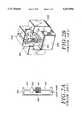
- FIG. 2Ais a plan view showing a light deflector 310.
- FIG. 2Bis a perspective view of the overall structure of a light deflecting device 300.
- This light deflecting device 300has a light deflector 310 consisting of a galvano mirror made up of a reflection mirror 312 and a driving coil 311.
- the light deflector 310is positioned in an external magnetic field generated by a yoke 328 and a coil 329.
- An alternating current coinciding with the resonant frequency of the light deflector 310flows into the coil 311 to attain a mirror displacement that is proportional to the current.
- This galvano mirrorcan easily increase the angle displacement in the reflection mirror 312 by increasing the applied current, thus allowing the light scanning angle to be increased.
- the light deflector 310 shown in FIGS. 2A and 2Bhas the following problems.
- the driving coil 311 placed on the same substrate as the reflection mirror 312requires a large current, which is likely to deform the mirror because of heating, thereby causing distortion of the reflected light image.
- an object of the present inventionis to provide a torsional vibrator and a light deflector using the torsional vibrator having a compact and inexpensive structure and performing stable operation such as light scanning.
- a second torsional vibrator having a responsively acting part and a second torsional springis formed on the outer side of a first torsional vibrator having a pair of torsional springs and a plate member (or a pair of torsional springs and a mirror), while the second torsional spring is fixed. Furthermore, a resonant frequency of the first torsional vibrator is set higher than that of the second torsional vibrator, and the responsively acting part in the second torsional vibrator is driven substantially at the first resonant frequency by an electromagnetic or electrostatic attraction force generating means. With such a structure, the angle amplitude at the second torsional vibrator reaches a maximum at its resonant frequency, while at a higher frequency the amplitude decreases as the driving frequency increases.
- the force applied to the responsively acting partforms a pair of forces.
- the amplitude on the side of the second torsional vibrator provided with the driving meansmay be small, so that the distance between the driving means and the second torsional vibrator may be set shorter, thus making it possible to obtain a large deflection angle or scanning angle with very little energy.
- FIG. 1Ais a perspective view showing an example of prior art vibrator
- FIG. 1Bis a sectional view showing the vibrator
- FIG. 2Ais a plan view showing an example of a prior art light deflecting device
- FIG. 2Bis a perspective view of the overall structure of the light deflecting device
- FIG. 3is a perspective view of one embodiment of the present invention.
- FIG. 4is a plan view of the vibrator shown in FIG. 3;
- FIG. 5is an explanatory diagram explaining the principle of the present invention.
- FIG. 6is a perspective view of another embodiment of the present invention.
- FIG. 7is a plan view of an example of a vibrator which has three degrees of freedom
- FIG. 8is a sectional view showing one embodiment of the present invention utilizing a pair of electrostatic forces
- FIG. 9Ais a perspective view showing one embodiment of the present invention utilizing a pair of electromagnetic forces.
- FIG. 9Bis a sectional view showing the embodiment shown in FIG. 9A.
- FIG. 3is a perspective view showing one embodiment of the present invention.
- FIG. 4is a plan view showing the configuration of the vibrator in FIG. 3.
- reference numeral 1denotes a vibrator with two degrees of freedom made of a magnetic material, having a first torsional vibrator 2 having a plate member 21 and a pair of first torsional springs 22, a second torsional vibrator 3 having an outer frame 31 and a pair of second torsional springs 32, and fixing parts 4.
- the first torsional springs 22 and the second torsional springs 32are aligned along the center axis of the plate member 21.
- a light deflecting deviceBy replacing the plate member 21 with a reflection mirror or disposing a reflection mirror on the plate-shaped member 21, a light deflecting device can be obtained.
- the present inventionwill be explained hereinafter primarily referring to examples of a light deflector.
- the plate member 21 forming a reflection mirror and the outer frame 31are so constructed to rotate around the first and second torsional springs 22 and 32.
- Two electromagnetic driving meansone having a first yoke 61 and a first coil 71 and the other having a second yoke 62 and a second coil 72, are arranged with a small distance between the electromagnetic driving means and the outer frame 31 in the vicinity of the outer frame 31, and on the right and left sides of the first and second torsional springs 22 and 32, respectively. Since the outer frame 31 acts in response to the driving means, it is hereinafter referred to as the responsively acting part.
- the fixing parts 4are fixed firmly onto a substrate 5 by stopping plates 8.
- FIG. 5shows the principle model of this vibrator, which has two degrees of freedom, i.e., each vibrator 2, 3, has one degree of freedom due to its rotation about the rotating axes of the respective spring 22, 23.
- the first torsional vibrator 2is illustrated by a dotted line in FIG. 5, and the model has a vibrator with a moment of inertia "I 1 ", a spring with a torsional spring constant "k” and a attenuation with an elastic constant "C”.
- the second torsional vibrator 3is shown in the model consisting of a vibrator with a moment of inertia "I 2 ", and a spring with a torsional spring constant "K". Since the attenuation that affects the second torsional vibrator is so small, it is neglected here.
- the amplitude "X" of the second torsional vibrator 3, to which a harmonic vibration force “Fe jwt " is applied and the displacement of the first torsional vibrator 2 "y”are expressed by the following equations.
- " ⁇ "is a vibration angular frequency.
- the resonant frequency of the first torsional vibrator 2is set much higher than the resonant frequency of the second torsional vibrator 3.
- the amplitude of the plate member (reflection mirror) 21may be increased, even if the distance between the second torsional vibrator 3 and the yokes 61 and 62 is small.
- the driving force for the driving currentcan be increased, thereby ensuring a large amplitude for a large plate member (reflection mirror) with a small driving energy.
- FIG. 6is a perspective view showing another embodiment of the present invention.
- fixed electrodes 91 and 92are arranged on opposite sides of the outer frame (the responsively acting part) 31. While the outer frame 31 is grounded via the fixed part 4, a voltage is applied alternately to the fixed electrode 91 or 92 via a switch SW, so that the electrostatic force generated between the two electrodes is utilized.
- the vibratorwhich has two degrees of freedom, is rotatingly vibrated in the same manner as the embodiment in FIG. 3 and FIG. 4 substantially at the resonant frequency of the first torsional vibrator.
- the electrostatic force Fcan be expressed as:
- the degrees of freedommay be three or more.
- FIG. 7shows an embodiment of a vibrator with three degrees of freedom, i.e., this embodiment comprises three discrete elements each of which is rotatable about an axis.
- reference numeral 41denotes a responsively acting part corresponding to the outer frame 31 in FIG. 4. Since all the other parts are identical with those in FIG. 4, their explanations are omitted here.
- FIG. 3 and FIG. 6use an unidirectional driving force
- a large force applied to the vibratormay generate a bending vibration in the supporting parts, thereby causing the scanning light to wobble in directions other than the required direction.
- the forceis inversely proportional to the square of the set gap distance, the generation of an excessive force may cause movable parts to get stuck to the fixed part, thereby rendering them inoperable.
- FIG. 8One embodiment, which excludes such a possibility, is shown in FIG. 8.
- two sets of electrodes 91 and 92 and electrodes 93 and 94are arranged in a manner that they are facing the front and rear surfaces of the outer frame 31 and are adequately spaced from the outer frame 31 (responsively acting part) in the vibrator 1 with two degrees of freedom.
- a voltageis applied alternately to the electrodes on the right and left sides in such a way that the voltage is applied to the electrodes on the front and rear in a reverse phase mode, so that the electrostatic force generated by this voltage application is utilized as a driving force.
- the electrostatic force generated in this embodimentforms a pair of forces with respect to the second torsional spring in the vibrator 1 with two degrees of freedom as its center, a low voltage is sufficient to obtain the same amplitude, and no force other than the rotating force acts on the spring, thus providing a stable light scanning operation.
- FIGS. 9A and 9Bshow another embodiment.
- FIG. 9Ashows a perspective view thereof, while FIG. 9B shows its cross section.
- a vibrator 10 with two degrees of freedomis arranged in such a manner that the first torsional vibrator 15 made of silicon, fabricated with a micromachining technique using photolithography, for example, is bonded with metallic second torsional vibrator 16.
- Reference numeral 11denotes a plate member (reflection-mirror).
- Reference numerals 12A and 12Bdenote first torsional springs.
- Reference numeral 13denotes an outer frame (responsively acting part).
- Reference numerals 14A and 14Bdenote; second torsional springs.
- a first permanent magnet 41A and a second permanent magnet 41Bare bonded to the outer frame (responsively acting part) 13 on the right and left sides thereof, a first coil 25A and a second coil 25B are fixed to a substrate 20 and arranged in the vicinity of the magnets 41A and 4B, and two currents, running in opposite directions, are fed to the coils 25A and 25B.
- the electromagnetic force that is generated therefromis utilized.
- the directions of the magnetic fluxes in the magnets 41A and 41Bare set in the same direction and currents having directions opposite to each other are supplied to the coils 25A and 25B, so that the force generated becomes a pair of forces, thereby providing the same effect as in the case of FIG. 8. Even if the magnetic fields in the bonded permanent magnets are in opposite directions and the directions of the currents flowing through the coils are in the same direction, this arrangement has the same effect.
- a first torsional vibrator having a plate member or a reflection mirror, and a pair of first torsional springsare coupled with a second torsional vibrator having a responsively acting part and a second torsional spring to form a vibrator with two degrees of freedom, and a driving force of a pair of forces is applied to the responsively acting part of the second torsional vibrator to drive the vibrator with the resonant frequency of the first torsional vibrator, so that the amplitude of the second torsional vibrator can be made much smaller than that of the first torsional vibrator.
- the driving meansis required to have a small gap between the driving means and the vibrator, e.g. electromagnetic or electrostatic driving means, which generates a driving force by placing the vibrator opposite the yokes or fixed electrodes.
- the amplitude of the plate member or the reflection mirrorcan be increased. Accordingly, a large scanning angle obtained in the present invention is applied to a light deflector.
- the electrostatic systemit is sufficient to simply arrange fixed electrodes opposite the vibrators, so that the number of parts used can be reduced, thereby making the device more compact. Also, since in this system the vibrators can be used as long as they are made of an electrically conductive material, a wider range of material selection is possible.
Landscapes
- Physics & Mathematics (AREA)
- Electromagnetism (AREA)
- General Physics & Mathematics (AREA)
- Engineering & Computer Science (AREA)
- Optics & Photonics (AREA)
- Artificial Intelligence (AREA)
- Toxicology (AREA)
- Computer Vision & Pattern Recognition (AREA)
- General Health & Medical Sciences (AREA)
- Theoretical Computer Science (AREA)
- Health & Medical Sciences (AREA)
- Mechanical Optical Scanning Systems (AREA)
- Micromachines (AREA)
- Manipulator (AREA)
- Laser Beam Printer (AREA)
Abstract
Description
The present application claims the rights of priority of Japanese Patent Application No. 270,543/1992, filed in Japan on Oct. 8, 1992, and Japanese Patent Application No. 291,839/1992, filed in Japan on Oct. 30, 1992, the subject matter of both applications being incorporated herein by reference.
The present invention relates to a torsional vibrator and a light deflector using the torsional vibrator that can be applied to scanning devices in optical devices such as electrophotographic copiers, laser printer image forming device or bar code reading devices.
The prior art includes the device shown in FIGS. 1A and 1B (Refer to U.S. Pat. No. 4,317,611).
In FIG. 1A,reference numeral 51 denotes a vibrator includingspan bands 52a and 52b and areflection mirror 53 which are formed integrally on a silicon plate, for example.Reference numeral 54 denotes a glass substrate. The reflection mirror 53 contacts aprotrusion 55 of thesubstrate 54, which has its two sides separated by a gap by means of arecess 56.Reference numerals 57a and 57b are electrodes disposed on thesubstrate 54. Then a voltage is applied from an external source across one of the electrodes and themirror 53, themirror 53 is pulled by an electrostatic attraction force and is thereby slanted, while light that is directed onto themirror 53 is scanned as indicated by the arrow in FIG. 1B. In other words, if themirror 53 slants by φ on either side, the light is deflected by 2φ. Thus, the device is constructed with few parts, so that it is very compact.
However, in the device shown in FIGS. 1A and 1B, if the distance between the electrodes is increased in order to increase the mirror deflection angle (the light scanning angle), a high voltage is necessary so that the device is not practical. Therefore, the device has the drawback that a scanning angle of only one or two degrees at most can be obtained.
Accordingly, an image forming-device, as shown in FIGS. 2A and 2B, has been proposed (Japanese Patent Application Laying-open No. 62-82,165/1988). FIG. 2A is a plan view showing alight deflector 310. FIG. 2B is a perspective view of the overall structure of alight deflecting device 300. Thislight deflecting device 300 has alight deflector 310 consisting of a galvano mirror made up of areflection mirror 312 and adriving coil 311. Thelight deflector 310 is positioned in an external magnetic field generated by ayoke 328 and acoil 329. An alternating current coinciding with the resonant frequency of thelight deflector 310 flows into thecoil 311 to attain a mirror displacement that is proportional to the current. This galvano mirror can easily increase the angle displacement in thereflection mirror 312 by increasing the applied current, thus allowing the light scanning angle to be increased.
However, thelight deflector 310 shown in FIGS. 2A and 2B has the following problems.
(1) Thedriving coil 311 placed on the same substrate as thereflection mirror 312 requires a large current, which is likely to deform the mirror because of heating, thereby causing distortion of the reflected light image.
(2) It is necessary to dispose a lead made of copper or silver on theligament 313 which functions as a torsional spring. If the ambient temperature changes, the resonant frequency and its Q changes and becomes unstable because of the difference in the linear expansion coefficients of the spring member and the lead.
Therefore, an object of the present invention is to provide a torsional vibrator and a light deflector using the torsional vibrator having a compact and inexpensive structure and performing stable operation such as light scanning.
In order to attain the object, in the present invention, a second torsional vibrator having a responsively acting part and a second torsional spring is formed on the outer side of a first torsional vibrator having a pair of torsional springs and a plate member (or a pair of torsional springs and a mirror), while the second torsional spring is fixed. Furthermore, a resonant frequency of the first torsional vibrator is set higher than that of the second torsional vibrator, and the responsively acting part in the second torsional vibrator is driven substantially at the first resonant frequency by an electromagnetic or electrostatic attraction force generating means. With such a structure, the angle amplitude at the second torsional vibrator reaches a maximum at its resonant frequency, while at a higher frequency the amplitude decreases as the driving frequency increases.
In other words, it is possible to reduce the amplitude at the second torsional vibrator and to increase the amplitude at the first torsional vibrator by driving the second torsional vibrator at the first resonant frequency.
The force applied to the responsively acting part forms a pair of forces. With such a structure, the amplitude on the side of the second torsional vibrator provided with the driving means may be small, so that the distance between the driving means and the second torsional vibrator may be set shorter, thus making it possible to obtain a large deflection angle or scanning angle with very little energy.
In addition, since a driving means that does not contact the plate member or the reflection mirror is used, no thermal distortion due to heating makes it possible to carry out stable operation, including light beam scanning.
The above and other objects, effects, features and advantages of the present invention will become more apparent from the following description of embodiments thereof taken in conjunction with the accompanying drawings.
In the accompanying drawings:
FIG. 1A is a perspective view showing an example of prior art vibrator;
FIG. 1B is a sectional view showing the vibrator;
FIG. 2A is a plan view showing an example of a prior art light deflecting device;
FIG. 2B is a perspective view of the overall structure of the light deflecting device;
FIG. 3 is a perspective view of one embodiment of the present invention;
FIG. 4 is a plan view of the vibrator shown in FIG. 3;
FIG. 5 is an explanatory diagram explaining the principle of the present invention;
FIG. 6 is a perspective view of another embodiment of the present invention;
FIG. 7 is a plan view of an example of a vibrator which has three degrees of freedom;
FIG. 8 is a sectional view showing one embodiment of the present invention utilizing a pair of electrostatic forces;
FIG. 9A is a perspective view showing one embodiment of the present invention utilizing a pair of electromagnetic forces; and
FIG. 9B is a sectional view showing the embodiment shown in FIG. 9A.
FIG. 3 is a perspective view showing one embodiment of the present invention. FIG. 4 is a plan view showing the configuration of the vibrator in FIG. 3.
In FIGS. 3 and 4, reference numeral 1 denotes a vibrator with two degrees of freedom made of a magnetic material, having a firsttorsional vibrator 2 having aplate member 21 and a pair of first torsional springs 22, a secondtorsional vibrator 3 having anouter frame 31 and a pair of second torsional springs 32, and fixingparts 4. The first torsional springs 22 and the second torsional springs 32 are aligned along the center axis of theplate member 21.
By replacing theplate member 21 with a reflection mirror or disposing a reflection mirror on the plate-shapedmember 21, a light deflecting device can be obtained. The present invention will be explained hereinafter primarily referring to examples of a light deflector.
Theplate member 21 forming a reflection mirror and theouter frame 31 are so constructed to rotate around the first and second torsional springs 22 and 32. Two electromagnetic driving means, one having afirst yoke 61 and afirst coil 71 and the other having asecond yoke 62 and asecond coil 72, are arranged with a small distance between the electromagnetic driving means and theouter frame 31 in the vicinity of theouter frame 31, and on the right and left sides of the first and second torsional springs 22 and 32, respectively. Since theouter frame 31 acts in response to the driving means, it is hereinafter referred to as the responsively acting part. The fixingparts 4 are fixed firmly onto a substrate 5 by stoppingplates 8.
With such a configuration, when a current is fed into thecoil coils coils outer frame 31, so that a force is generated to pull theouter frame 31 made of a magnetic material in the vicinity of theyokes coils vibrators
FIG. 5 shows the principle model of this vibrator, which has two degrees of freedom, i.e., eachvibrator respective spring 22, 23.
The firsttorsional vibrator 2 is illustrated by a dotted line in FIG. 5, and the model has a vibrator with a moment of inertia "I1 ", a spring with a torsional spring constant "k" and a attenuation with an elastic constant "C". The secondtorsional vibrator 3 is shown in the model consisting of a vibrator with a moment of inertia "I2 ", and a spring with a torsional spring constant "K". Since the attenuation that affects the second torsional vibrator is so small, it is neglected here.
The amplitude "X" of the secondtorsional vibrator 3, to which a harmonic vibration force "Fejwt " is applied and the displacement of the firsttorsional vibrator 2 "y" are expressed by the following equations. Here, "ω" is a vibration angular frequency.
|x|=F·{(k-I.sub.1 ω.sup.2).sup.2 +(Cω).sup.2 }.sup.1/2 /|Δ(ω)|(1)y=F·{k.sup.2 -(Cω).sup.2 }.sup.1/2 /|Δ(ω)| (2)|Δ(ω)|=[{(k-I.sub.2 ω.sup.2)(k-I.sub.1 ω.sup.2)-I.sub.1 kω.sup.2 }.sup.2 +(Cω).sup.2 {K-(I.sub.1 +I.sub.2)ω.sup.2 }.sup.2 ].sup.1/2 (3)Assuming that the attenuation that affects the first torsional vibrator is so small (like the attenuation in the second torsional vibrator) that it can be neglected, the amplitude "x" for the second torsional vibrator is give by the following equation when C=0:
|x|=F|k-I.sub.1 ω.sup.2 |/|(K-I.sub.2 ω.sup.2)(k-I.sub.1 ω.sup.2)-I.sub.1 kω.sup.2 | (4)
If the second torsional vibrator is driven by the resonant frequency of the first torsional vibrator: f=2πω=2π(k/I1)1/2, then
|x|=0.
On the other hand, the amplitude of the first torsional vibrator "y" is given by the following equation:
|y|=F|k|/|(K-I.sub.2 ω.sup.2)(k-I.sub.1 ω.sup.2)-I.sub.1 kω.sup.2 |=F/|k|,
Thus, the amplitude "y" that is proportional to the driving force F can be obtained.
In this embodiment, the resonant frequency of the firsttorsional vibrator 2 is set much higher than the resonant frequency of the secondtorsional vibrator 3. As a result, it is possible to suppress the amplitude of the secondtorsional vibrator 3, even if the vibrator is driven at a frequency that is slightly deviated from the resonant frequency of the firsttorsional vibrator 2. As a result, the amplitude of the plate member (reflection mirror) 21 may be increased, even if the distance between the secondtorsional vibrator 3 and theyokes
FIG. 6 is a perspective view showing another embodiment of the present invention.
In this embodiment, fixedelectrodes outer frame 31 is grounded via thefixed part 4, a voltage is applied alternately to the fixedelectrode
The electrostatic force F can be expressed as:
"F"=ε·ε.sub.0 ·S·V/d.sup.2,
where "d" is a gap distance, "S" is the electrode area, "V" is the applied voltage, "ε" is the specific dielectric constant, and "ε0 " is the dielectric constant vacuum.
This means that a very low voltage is sufficient to obtain a large force if a small gap value can be set. In other words, utilizing a torsional vibrator described above can realize a large vibration amplitude of the plate member (reflection mirror) with a low voltage. In addition, such an electrostatic driving system offers the advantage that a more compact structure is facilitated because of fewer parts than an electromagnetic driving system having a plurality of yokes and coils, since it is sufficient to simply arrange the fixed electrodes in the electrostatic driving system.
In the above embodiments, the degrees of freedom may be three or more.
FIG. 7 shows an embodiment of a vibrator with three degrees of freedom, i.e., this embodiment comprises three discrete elements each of which is rotatable about an axis.
In FIG. 7,reference numeral 41 denotes a responsively acting part corresponding to theouter frame 31 in FIG. 4. Since all the other parts are identical with those in FIG. 4, their explanations are omitted here. With the vibrator thus structured, it is possible to make a relatively large plate member or reflection mirror, even if the size of the outer shape is made smaller.
Further, because the embodiments shown in FIG. 3 and FIG. 6 use an unidirectional driving force, a large force applied to the vibrator may generate a bending vibration in the supporting parts, thereby causing the scanning light to wobble in directions other than the required direction. In addition, since the force is inversely proportional to the square of the set gap distance, the generation of an excessive force may cause movable parts to get stuck to the fixed part, thereby rendering them inoperable.
One embodiment, which excludes such a possibility, is shown in FIG. 8. In this embodiment, two sets ofelectrodes electrodes outer frame 31 and are adequately spaced from the outer frame 31 (responsively acting part) in the vibrator 1 with two degrees of freedom. A voltage is applied alternately to the electrodes on the right and left sides in such a way that the voltage is applied to the electrodes on the front and rear in a reverse phase mode, so that the electrostatic force generated by this voltage application is utilized as a driving force.
Since the electrostatic force generated in this embodiment forms a pair of forces with respect to the second torsional spring in the vibrator 1 with two degrees of freedom as its center, a low voltage is sufficient to obtain the same amplitude, and no force other than the rotating force acts on the spring, thus providing a stable light scanning operation.
FIGS. 9A and 9B show another embodiment. FIG. 9A shows a perspective view thereof, while FIG. 9B shows its cross section. In this embodiment, a vibrator 10 with two degrees of freedom is arranged in such a manner that the first torsional vibrator 15 made of silicon, fabricated with a micromachining technique using photolithography, for example, is bonded with metallic secondtorsional vibrator 16.Reference numeral 11 denotes a plate member (reflection-mirror).Reference numerals Reference numeral 13 denotes an outer frame (responsively acting part).Reference numerals 14A and 14B denote; second torsional springs.
A firstpermanent magnet 41A and a secondpermanent magnet 41B are bonded to the outer frame (responsively acting part) 13 on the right and left sides thereof, afirst coil 25A and asecond coil 25B are fixed to asubstrate 20 and arranged in the vicinity of themagnets 41A and 4B, and two currents, running in opposite directions, are fed to thecoils magnets coils
According to the present invention, a first torsional vibrator having a plate member or a reflection mirror, and a pair of first torsional springs are coupled with a second torsional vibrator having a responsively acting part and a second torsional spring to form a vibrator with two degrees of freedom, and a driving force of a pair of forces is applied to the responsively acting part of the second torsional vibrator to drive the vibrator with the resonant frequency of the first torsional vibrator, so that the amplitude of the second torsional vibrator can be made much smaller than that of the first torsional vibrator.
The driving means is required to have a small gap between the driving means and the vibrator, e.g. electromagnetic or electrostatic driving means, which generates a driving force by placing the vibrator opposite the yokes or fixed electrodes. However contrast, according to this invention, the amplitude of the plate member or the reflection mirror can be increased. Accordingly, a large scanning angle obtained in the present invention is applied to a light deflector.
In a device that uses a pair of forces, no force other than the rotating force is applied to the supporting part, so that the bending deformation in the springs is eliminated. This means that there will be little wobble in the light scanning operation, thereby realizing stable scanning.
In addition, if a magnetic material is used in the vibrators of the electromagnetic system, it is not required to from a coil and a lead on the vibrator. As a result, stable light beam scanning operation becomes possible without any heat deformation of the mirror caused by the electric current applied to the coils.
Furthermore, in the electrostatic system, it is sufficient to simply arrange fixed electrodes opposite the vibrators, so that the number of parts used can be reduced, thereby making the device more compact. Also, since in this system the vibrators can be used as long as they are made of an electrically conductive material, a wider range of material selection is possible.
The present invention has been described in detail with respect to preferred embodiments, and it will now be that changes and modifications may be made without departing from the invention in its broader aspects, and it is the intention, therefore, in the appended claims to cover all such changes and modifications as fall within the true spirit of the invention.
Claims (11)
1. A torsional vibrator with at least two degrees of freedom, comprising:
a first vibrator having a plate member and a first torsional spring, said first vibrator having a first resonant frequency;
a second vibrator having a second resonant frequency lower than the first resonant frequency, and having a responsively acting part connected to said first vibrator, and a second torsional spring, said second torsional spring being coaxial with said first torsional spring; and,
drive means for rotatingly vibrating said responsively acting part substantially at the first resonant frequency of said first vibrator.
2. A light deflector having a torsional vibrator with at least two degrees of freedom, said light deflector comprising:
a first vibrator having a light reflection mirror and a first torsional spring, said first vibrator having a first resonant frequency;
a second vibrator having a second resonant frequency lower than the first resonant frequency, and having a responsively acting part connected to said first vibrator, and a second torsional spring, said second torsional spring being coaxial with said first torsional spring; and
drive means for rotatingly vibrating said responsively acting part substantially at the first resonant frequency of said first vibrator with at least one driving force.
3. A light deflector as claimed in claim 2, wherein said at least one driving force is an electromagnetic force.
4. A light deflector as claimed in claim 2, wherein said at least one driving force is an electrostatic force.
5. A light deflector having a torsional vibrator with at least two degrees of freedom, said light deflector comprising:
a first vibrator having a light reflection mirror and a first torsional spring, said first vibrator having a first resonant frequency;
a second vibrator having a second resonant frequency lower than the first resonant frequency, and having a responsively acting part connected to said first vibrator, and a second torsional spring, said second torsional spring being coaxial with said first torsional spring; and
drive means for driving said responsively acting part with a pair of driving forces, said second spring as its center as a driving force, said responsively acting part being thereby rotatingly vibrated substantially at the first resonant frequency of said first vibrator.
6. A light deflector as claimed in claim 5, wherein said pair of driving forces are electromagnetic forces.
7. A light deflector as claimed in claim 5, wherein said pair of driving forces are electrostatic forces.
8. A light deflector comprising:
a torsional vibrator with at least two degrees of freedom made of magnetic material, including:
a first vibrator having a light reflection mirror and a pair of first torsional springs, said pair of first torsional springs being formed along a center axis of said light reflection mirror, and
a second vibrator having a responsively acting part provided on an outer side of said first vibrator and a pair of second torsional springs, said pair of second torsional springs being formed along said center axis of said light reflection mirror;
a plurality of fixing parts each attached to a respective second torsional spring;
a substrate for supporting said fixing parts of said torsional vibrator with at least two degrees of freedom; and
an electromagnetic driving means for generating an electromagnetic force to rotate said responsively acting part around said center axis of said light reflection mirror, said electromagnetic driving means including first and second yokes and first and second coils arranged opposite to said responsively acting part and on opposite sides of said center axis of said light reflection mirror, said responsively acting part being rotatingly vibrated by said electromagnetic driving means substantially at a resonant frequency of said first vibrator.
9. A light defelctor comprising:
a torsional vibrator with two degrees of freedom made of electrically conductive material, including:
a first vibrator having a light reflection mirror and a pair of first torsional springs, said pair of first torsional springs being formed along a center axis of said light reflection mirror, said first vibrator having a first resonant frequency, and
a second vibrator having a second resonant frequency lower than the first resonant frequency, and having a responsively acting part provided on an outer side of said first vibrator, and a pair of second torsional springs, said pair of second torsional springs being formed along said center axis of said light reflection mirror so as to be coaxial with said pair of first torsional springs;
a substrate for supporting fixed parts of said torsional vibrator with two degrees of freedom; and
an electrostatic driving means for generating an electrostatic force to rotate said responsively acting part around said center axis of said light reflection mirror, said electrostatic driving means including a pair of fixed electrodes arranged opposite to said responsively acting part and on opposite sides of said center axis of said light reflection mirror, said responsively acting part being rotatingly vibrated by said electrostatic driving means substantially at the first resonant frequency of said first vibrator.
10. A light deflector comprising:
a torsional vibrator with two degrees of freedom made of electrically conductive material, including:
a first vibrator having a light reflection mirror and a pair of first torsional springs, said pair of first torsional springs being formed along a center axis of said light reflection mirror, said first vibrator having a first resonant frequency, and
a second vibrator having a second resonant frequency lower than the first resonant frequency, and having a responsively acting part provided on an outer side of said first vibrator, and a pair of second torsional springs, said pair of second torsional springs being formed along said center axis of said light reflection mirror so as to be coaxial with said pair of first torsional springs;
a substrate for supporting fixed parts of said torsional vibrator with two degrees of freedom; and
an electrostatic driving means for generating a pair of electrostatic forces to rotate said responsively acting part around said center axis of said light reflection mirror, said electrostatic driving means including two pairs of fixed electrodes arranged on opposite sides of front and rear surfaces of said responsively acting part and on opposite sides of said center axis of said light reflecting mirror, said responsively acting part being provided with said pair of electrostatic forces and rotatingly vibrated by said electrostatic driving means substantially at the first resonant frequency of said first vibrator.
11. A light deflector comprising:
a torsional vibrator with two degrees of freedom, including:
a first vibrator having a light reflection mirror and a pair of first torsional springs, said pair of first torsional springs being formed along a center axis of said light reflection mirror, said first vibrator having a first resonant frequency, and
a second vibrator having a second resonant frequency lower than the first resonant frequency, and having a responsively acting part provided on an outer side of said first vibrator, and a pair of second torsional springs, said pair of second torsional springs being formed along said center axis of said light reflection mirror so as to be coaxial with said pair of first torsional springs;
a substrate for supporting fixed parts of said torsional vibrator with two degrees of freedom; and
an electromagnetic driving means for generating a pair of electromagnetic forces to rotate said responsively acting part around said center axis of said light reflection mirror, said electromagnetic driving means including first and second permanent magnets bonded to opposite sides of said responsively acting part, and first and second coils fixed to said substrate and arranged opposite said first and second permanent magnets, responsively, said responsively acting part being provided with said pair of electromagnetic forces and being thereby rotatingly vibrated by said electromagnetic driving means substantially at the first resonant frequency of said first vibrator.
Applications Claiming Priority (4)
| Application Number | Priority Date | Filing Date | Title |
|---|---|---|---|
| JP4-270543 | 1992-10-08 | ||
| JP27054392 | 1992-10-08 | ||
| JP4-291839 | 1992-10-30 | ||
| JP4291839AJP3003429B2 (en) | 1992-10-08 | 1992-10-30 | Torsional vibrator and optical deflector |
Publications (1)
| Publication Number | Publication Date |
|---|---|
| US5543956Atrue US5543956A (en) | 1996-08-06 |
Family
ID=26549253
Family Applications (1)
| Application Number | Title | Priority Date | Filing Date |
|---|---|---|---|
| US08/132,291Expired - Fee RelatedUS5543956A (en) | 1992-10-08 | 1993-10-06 | Torsional vibrators and light deflectors using the torsional vibrator |
Country Status (4)
| Country | Link |
|---|---|
| US (1) | US5543956A (en) |
| JP (1) | JP3003429B2 (en) |
| DE (1) | DE4334267C2 (en) |
| GB (1) | GB2271436B (en) |
Cited By (93)
| Publication number | Priority date | Publication date | Assignee | Title |
|---|---|---|---|---|
| WO1997023800A1 (en)* | 1995-12-26 | 1997-07-03 | Xros, Inc. | Compact document scanner or printer engine |
| US5684631A (en)* | 1996-05-13 | 1997-11-04 | Lucent Technologies Inc. | Optical modulator/switch including reflective zone plate and related method of use |
| US5691477A (en)* | 1995-11-21 | 1997-11-25 | Pirelli Coordinamento Pneumatici, S.P.A. | Torsional vibrator |
| US5912608A (en)* | 1995-05-26 | 1999-06-15 | The Nippon Signal Co., Ltd. | Planar type electromagnetic actuator |
| US5969465A (en)* | 1997-04-01 | 1999-10-19 | Xros, Inc. | Adjusting operating characteristics of micromachined torsional oscillators |
| US5999303A (en)* | 1997-03-24 | 1999-12-07 | Seagate Technology Inc. | Micro-machined mirror using tethered elements |
| US6059188A (en)* | 1993-10-25 | 2000-05-09 | Symbol Technologies | Packaged mirror including mirror travel stops |
| US6064779A (en)* | 1997-07-23 | 2000-05-16 | Xros, Inc. | Handheld document scanner |
| US6086209A (en)* | 1998-04-20 | 2000-07-11 | Sony Corporation | Mirror holder and optical axis correcting device using the same |
| EP1054285A1 (en)* | 1999-05-20 | 2000-11-22 | Olympus Optical Co., Ltd. | Torsional rocker |
| US6198565B1 (en)* | 1998-11-16 | 2001-03-06 | Victor Company Of Japan, Limited | Light deflection element and display apparatus using same |
| US6229139B1 (en) | 1998-07-23 | 2001-05-08 | Xros, Inc. | Handheld document scanner |
| US6259548B1 (en)* | 1999-05-28 | 2001-07-10 | Mitsubishi Denki Kabushiki Kaisha | Micro-mirror device |
| US6334573B1 (en)* | 1990-05-29 | 2002-01-01 | Symbol Technologies, Inc. | Integrated scanner on a common substrate having an omnidirectional mirror |
| US20020005976A1 (en)* | 2000-03-24 | 2002-01-17 | Behrang Behin | Multi-layer, self-aligned vertical combdrive electrostatic actuators and fabrication methods |
| US6467345B1 (en) | 1993-10-18 | 2002-10-22 | Xros, Inc. | Method of operating micromachined members coupled for relative rotation |
| US6556737B1 (en) | 1999-08-02 | 2003-04-29 | Integrated Micromachines, Inc. | Silicon bulk-micromachined electromagnetic fiber-optics bypass microswitch |
| US6593677B2 (en) | 2000-03-24 | 2003-07-15 | Onix Microsystems, Inc. | Biased rotatable combdrive devices and methods |
| US6608297B2 (en) | 1997-07-23 | 2003-08-19 | Xeros, Inc. | Scanner document speed encoder |
| US20030184189A1 (en)* | 2002-03-29 | 2003-10-02 | Sinclair Michael J. | Electrostatic bimorph actuator |
| US6629642B1 (en) | 1996-08-02 | 2003-10-07 | Symbol Technologies, Inc. | Data system and method for accessing a computer network using a collection of bar code symbols |
| US6629461B2 (en) | 2000-03-24 | 2003-10-07 | Onix Microsystems, Inc. | Biased rotatable combdrive actuator methods |
| US20030210323A1 (en)* | 2002-05-07 | 2003-11-13 | Turner Arthur Monroe | Dynamic laser printer scanning alignment using a torsional hinge mirror |
| US6657764B1 (en)* | 1999-03-18 | 2003-12-02 | The Trustees Of Boston University | Very large angle integrated optical scanner made with an array of piezoelectric monomorphs |
| US6717325B2 (en)* | 2002-03-06 | 2004-04-06 | Glimmerglass Networks, Inc. | Method and apparatus for actuation of a two-axis MEMS device using three actuation elements |
| US6729545B2 (en)* | 1990-05-29 | 2004-05-04 | Symbol Technologies, Inc. | Integrated scanner on a common substrate having an omnidirectional mirror |
| US20040120057A1 (en)* | 2002-12-20 | 2004-06-24 | Andreas Niendorf | Apparatus, method and system for providing enhanced mechanical protection for thin beams |
| US20040120022A1 (en)* | 2002-12-23 | 2004-06-24 | Cannon Roger S. | Stationary coil oscillator scanning system |
| US20040119002A1 (en)* | 2002-12-23 | 2004-06-24 | Bush Craig P. | Scanning with feedback sensor |
| US20040119811A1 (en)* | 2002-12-23 | 2004-06-24 | Bush Craig P. | Scanning with multiple oscillating scanners |
| US20040120023A1 (en)* | 2002-12-23 | 2004-06-24 | Bush Craig P. | Dynamic torsion oscillator mirror operation |
| US20040119810A1 (en)* | 2002-12-23 | 2004-06-24 | Cannon Roger S. | Galvonometric scanning and imaging with multiple beams reflected from an oscillator |
| US20040125198A1 (en)* | 2002-03-08 | 2004-07-01 | Klement Martin Christopher | Torsion oscillator stabilization |
| US20040130765A1 (en)* | 2001-04-12 | 2004-07-08 | Thomas Gessner | Resonance scanner |
| US20040212907A1 (en)* | 2003-04-24 | 2004-10-28 | Mohiuddin Mala | Micro-electro-mechanical-system two dimensional mirror with articulated suspension structures for high fill factor arrays |
| US20040233498A1 (en)* | 2000-10-31 | 2004-11-25 | Microsoft Corporation | Microelectrical mechanical structure (MEMS) optical modulator and optical display system |
| US20040263937A1 (en)* | 2003-05-16 | 2004-12-30 | Mitsumi Fujii | Optical scanning apparatus, optical writing apparatus, image forming apparatus, and method of driving vibration mirror |
| US20050011191A1 (en)* | 2001-12-31 | 2005-01-20 | Microsoft Corporation | Unilateral thermal buckle beam actuator |
| US20050024701A1 (en)* | 2003-07-29 | 2005-02-03 | Cannon Roger S. | Resonant oscillating scanning device with multiple light sources |
| US20050035682A1 (en)* | 2003-08-12 | 2005-02-17 | Fujitsu Limited | Micro-oscillation element and method for driving the same |
| US6870560B2 (en) | 2002-12-23 | 2005-03-22 | Lexmark International, Inc. | Bi-directional galvonometric scanning and imaging |
| US20050088715A1 (en)* | 2003-09-05 | 2005-04-28 | Mitsuhiro Yoda | Actuator |
| EP1528422A1 (en)* | 2003-10-30 | 2005-05-04 | Olympus Corporation | Light deflector |
| US20050093964A1 (en)* | 2003-10-20 | 2005-05-05 | Lexmark International, Inc. | Method and apparatus for reducing Q factor in an oscillating laser scanner |
| US20050101878A1 (en)* | 2001-04-18 | 2005-05-12 | Daly Christopher N. | Method and apparatus for measurement of evoked neural response |
| US20050116551A1 (en)* | 2003-10-29 | 2005-06-02 | Mitsuhiro Yoda | Actuator |
| US20050128552A1 (en)* | 2003-12-16 | 2005-06-16 | Canon Kabushiki Kaisha | Torsional vibrator, optical deflector and image forming apparatus |
| US20050134143A1 (en)* | 2003-10-20 | 2005-06-23 | Lexmark International, Inc. | Optical system for torsion oscillator laser scanning unit |
| US20050173770A1 (en)* | 2004-02-09 | 2005-08-11 | Linden Kelly D. | Method and apparatus for making a MEMS scanner |
| US20050219674A1 (en)* | 2002-11-26 | 2005-10-06 | Brother Kogyo Kabushiki Kaisha | Optical scanning apparatus and image forming apparatus |
| US20050253055A1 (en)* | 2004-05-14 | 2005-11-17 | Microvision, Inc., A Corporation Of The State Of Delaware | MEMS device having simplified drive |
| EP1586933A4 (en)* | 2002-11-26 | 2006-02-22 | Brother Ind Ltd | LIGHT SCANNING DEVICE AND IMAGE FORMING DEVICE |
| US20060125347A1 (en)* | 2004-12-15 | 2006-06-15 | Seiko Epson Corporation | Actuator |
| US7064879B1 (en)* | 2000-04-07 | 2006-06-20 | Microsoft Corporation | Magnetically actuated microelectrochemical systems actuator |
| US20060152785A1 (en)* | 2003-12-25 | 2006-07-13 | Canon Kabushiki Kaisha | Micro-oscillating member, light-deflector, and image-forming apparatus |
| US20060198006A1 (en)* | 2005-03-02 | 2006-09-07 | Canon Kabushiki Kaisha | Light deflector |
| US20060222312A1 (en)* | 2005-02-16 | 2006-10-05 | Mohiuddin Mala | Articulated MEMs structures |
| US20060279364A1 (en)* | 2005-06-14 | 2006-12-14 | Lexmark International, Inc. | Determining operating point of feedback controller applied to operation of oscillating scanning device |
| US20060291406A1 (en)* | 2005-06-23 | 2006-12-28 | Lexmark International, Inc. | Device authentication method and system |
| US20070008401A1 (en)* | 2005-07-07 | 2007-01-11 | Lexmark International, Inc. | Multiharmonic galvanometric scanning device |
| US20070025659A1 (en)* | 2005-06-22 | 2007-02-01 | Seiko Epson Corporation | Actuator |
| US20070182276A1 (en)* | 2006-02-04 | 2007-08-09 | Stereo Display, Inc. | Multi-step microactuator |
| US20070188839A1 (en)* | 2006-02-15 | 2007-08-16 | Yoshihiro Ishibe | Optical scanning apparatus and image forming apparatus using same |
| US20070268549A1 (en)* | 2003-08-12 | 2007-11-22 | Fujitsu Limited | Micro-oscillation element |
| US20080001690A1 (en)* | 2006-07-03 | 2008-01-03 | National Tsing Hua University | Micro scanner and manufacturing process, driving structure and driving method therefor |
| US20080055688A1 (en)* | 2006-09-01 | 2008-03-06 | Canon Kabushiki Kaisha | Optical deflecting device and image forming apparatus using the same |
| US20080068688A1 (en)* | 2006-09-19 | 2008-03-20 | Seiko Epson Corporation | Actuator, optical scanner, and image forming apparatus |
| US7388699B1 (en) | 2005-07-11 | 2008-06-17 | Coffee Curtis L | Musical laser display device |
| US20090047527A1 (en)* | 2007-08-15 | 2009-02-19 | National Tsing Hua University | Magnetic element and manufacturing method therefor |
| US7498681B1 (en)* | 2007-03-21 | 2009-03-03 | Sandia Corporation | Mechanical vibration to electrical energy converter |
| US7636101B2 (en) | 2005-02-09 | 2009-12-22 | Microvision, Inc. | MEMS scanner adapted to a laser printer |
| WO2011033496A1 (en) | 2009-09-16 | 2011-03-24 | Maradin Technologies Ltd. | Micro coil apparatus and manufacturing methods therefor |
| CN101477248B (en)* | 2009-01-22 | 2011-04-13 | 中国科学院光电技术研究所 | Double torsion bar resonance scanning reflector |
| US20110148554A1 (en)* | 2008-08-22 | 2011-06-23 | Korea Advanced Institute Of Science And Technology | Electromagnetic multi-axis actuator |
| US20110199172A1 (en)* | 2008-09-25 | 2011-08-18 | Tjalf Pirk | Magnetic yoke, micromechanical component, and method for the manufacture thereof |
| US8411343B2 (en) | 2006-09-27 | 2013-04-02 | National Institute Of Advanced Industrial Science And Technology | Optical scanning device |
| CN103282819A (en)* | 2010-12-27 | 2013-09-04 | 罗伯特·博世有限公司 | Magnetically drivable micromirror |
| DE102012222988A1 (en)* | 2012-12-12 | 2014-06-12 | Fraunhofer-Gesellschaft zur Förderung der angewandten Forschung e.V. | Micromechanical resonator arrangement |
| CN104101981A (en)* | 2013-04-11 | 2014-10-15 | 弗兰霍菲尔运输应用研究公司 | Microactuator arrangement for deflecting electromagnetic radiation |
| DE102013223933A1 (en) | 2013-11-22 | 2015-05-28 | Fraunhofer-Gesellschaft zur Förderung der angewandten Forschung e.V. | Micromirror array |
| US20160122178A1 (en)* | 2013-05-30 | 2016-05-05 | Pioneer Micro Technology Corporation | Driving apparatus |
| US20170033654A1 (en)* | 2015-07-31 | 2017-02-02 | AAC Technologies Pte. Ltd. | Vibration Motor |
| US20170033674A1 (en)* | 2013-12-19 | 2017-02-02 | Pioneer Corporation | Driving apparatus |
| US20180265348A1 (en)* | 2017-03-16 | 2018-09-20 | Commissariat A L'energie Atomique Et Aux Energies Alternatives | Micro-device having a plurality of mobile elements arranged in a plurality of embedded cavities |
| US10649072B2 (en) | 2017-05-10 | 2020-05-12 | Massachusetts Institute Of Technology | LiDAR device based on scanning mirrors array and multi-frequency laser modulation |
| US20200295647A1 (en)* | 2018-10-24 | 2020-09-17 | Mplus Co., Ltd. | Sound vibration actuator |
| US10877263B2 (en)* | 2017-10-30 | 2020-12-29 | Infineon Technologies Ag | Mirror device having leaf spring with openings |
| US20210399617A1 (en)* | 2019-03-12 | 2021-12-23 | Alps Alpine Co., Ltd. | Electromagnetic drive device and operation device |
| US11454803B2 (en) | 2017-04-11 | 2022-09-27 | Fraunhofer-Gesellschaft Zur Foerderung Der Angewandten Forschung E.V. | Micromechanical mirror device |
| US20220360156A1 (en)* | 2021-05-06 | 2022-11-10 | Aac Microtech (Changzhou) Co., Ltd. | Linear vibration motor |
| US20230179121A1 (en)* | 2021-12-02 | 2023-06-08 | Commissariat A L'energie Atomique Et Aux Energies Alternatives | Electromagnetic transducer for harvesting vibratory energy |
| US11784548B2 (en)* | 2019-12-11 | 2023-10-10 | Meta Platforms, Inc. | Vibrating actuator with two resonant frequencies and two moving parts |
| CN117192762A (en)* | 2023-11-07 | 2023-12-08 | 中国电子科技集团公司信息科学研究院 | Electrostatic MEMS fabry-perot filter and image forming apparatus |
Families Citing this family (31)
| Publication number | Priority date | Publication date | Assignee | Title |
|---|---|---|---|---|
| JP2722314B2 (en)* | 1993-12-20 | 1998-03-04 | 日本信号株式会社 | Planar type galvanometer mirror and method of manufacturing the same |
| JP3011144B2 (en)* | 1997-07-31 | 2000-02-21 | 日本電気株式会社 | Optical scanner and its driving method |
| JP5143102B2 (en)* | 1997-12-09 | 2013-02-13 | オリンパス株式会社 | Manufacturing method of optical deflector |
| JP4776779B2 (en)* | 1998-09-02 | 2011-09-21 | カイロス・インク | Microfabricated members that are connected by torsional flexure and rotate relatively |
| DE19857946C1 (en)* | 1998-12-16 | 2000-01-20 | Bosch Gmbh Robert | Micro vibrating mirror for displays, scanners and optical monitoring systems |
| DE19941045A1 (en)* | 1999-08-28 | 2001-04-12 | Bosch Gmbh Robert | Micro vibrating device |
| DE19963382A1 (en)* | 1999-12-28 | 2001-07-12 | Bosch Gmbh Robert | Micromirror |
| KR100719102B1 (en)* | 2000-11-03 | 2007-05-17 | 삼성전자주식회사 | Micro drive |
| KR100716957B1 (en)* | 2000-11-30 | 2007-05-10 | 삼성전자주식회사 | Micromirror actuator and its manufacturing method |
| JP3740444B2 (en)* | 2001-07-11 | 2006-02-01 | キヤノン株式会社 | Optical deflector, optical equipment using the same, torsional oscillator |
| US7605370B2 (en)* | 2001-08-31 | 2009-10-20 | Ric Investments, Llc | Microspectrometer gas analyzer |
| US7296750B2 (en)* | 2003-03-13 | 2007-11-20 | Symbol Technologies, Inc. | Inertial drive scanning arrangement and method |
| IL165212A (en) | 2004-11-15 | 2012-05-31 | Elbit Systems Electro Optics Elop Ltd | Device for scanning light |
| JP2006239842A (en)* | 2005-03-04 | 2006-09-14 | Seiko Epson Corp | Method for adjusting resonance frequency of actuator and actuator |
| DE102005033800B4 (en)* | 2005-07-13 | 2016-09-15 | Fraunhofer-Gesellschaft zur Förderung der angewandten Forschung e.V. | Micromechanical optical element with a reflective surface and its use |
| JP2008039861A (en)* | 2006-08-01 | 2008-02-21 | Seiko Epson Corp | Optical device |
| JP5103876B2 (en)* | 2006-11-16 | 2012-12-19 | 株式会社デンソー | Two-dimensional optical scanning device |
| CN104160240B (en) | 2012-02-15 | 2017-02-22 | 苹果公司 | Scanning depth engine |
| EP2828833B1 (en) | 2012-03-22 | 2017-03-08 | Apple Inc. | Gimbaled scanning mirror array |
| WO2014016794A1 (en) | 2012-07-26 | 2014-01-30 | Primesense Ltd. | Dual-axis scanning mirror |
| WO2014064606A1 (en) | 2012-10-23 | 2014-05-01 | Primesense Ltd. | Production of micro-mechanical devices |
| JP2014126725A (en)* | 2012-12-27 | 2014-07-07 | Funai Electric Co Ltd | Scanning mirror device |
| JP6444035B2 (en)* | 2014-02-07 | 2018-12-26 | 国立大学法人信州大学 | Electromagnetic vibration actuator |
| US9835853B1 (en) | 2014-11-26 | 2017-12-05 | Apple Inc. | MEMS scanner with mirrors of different sizes |
| US9784838B1 (en) | 2014-11-26 | 2017-10-10 | Apple Inc. | Compact scanner with gimbaled optics |
| US9798135B2 (en) | 2015-02-16 | 2017-10-24 | Apple Inc. | Hybrid MEMS scanning module |
| US9897801B2 (en) | 2015-09-30 | 2018-02-20 | Apple Inc. | Multi-hinge mirror assembly |
| US9703096B2 (en) | 2015-09-30 | 2017-07-11 | Apple Inc. | Asymmetric MEMS mirror assembly |
| US10488652B2 (en) | 2016-09-21 | 2019-11-26 | Apple Inc. | Prism-based scanner |
| WO2021034371A1 (en) | 2019-08-18 | 2021-02-25 | Apple Inc. | Force-balanced micromirror with electromagnetic actuation |
| CN214503997U (en)* | 2020-03-06 | 2021-10-26 | 台湾东电化股份有限公司 | Optical element driving mechanism |
Citations (15)
| Publication number | Priority date | Publication date | Assignee | Title |
|---|---|---|---|---|
| DE664983C (en)* | 1932-10-13 | 1938-10-01 | Telefunken Gmbh | Oscillator or resonator designed as a piezoelectric crystal with low radiation damping |
| US3642344A (en)* | 1970-11-27 | 1972-02-15 | Honeywell Inc | Optical scanner having high-frequency torsional oscillator |
| US3666974A (en)* | 1970-01-16 | 1972-05-30 | Bulova Watch Co Inc | Torsional fork transducers |
| US3758199A (en)* | 1971-11-22 | 1973-09-11 | Sperry Rand Corp | Piezoelectrically actuated light deflector |
| GB2075762A (en)* | 1980-04-04 | 1981-11-18 | Yokogawa Electric Works Ltd | Mechanical vibrating element |
| US4317611A (en)* | 1980-05-19 | 1982-03-02 | International Business Machines Corporation | Optical ray deflection apparatus |
| JPS60107017A (en)* | 1983-11-16 | 1985-06-12 | Hitachi Ltd | light deflection element |
| GB2175705A (en)* | 1985-05-24 | 1986-12-03 | Stc Plc | Dirigible reflector and mounting made of single crystal material |
| JPS6382165A (en)* | 1986-09-26 | 1988-04-12 | Konica Corp | Picture forming device |
| JPH0195406A (en)* | 1987-10-06 | 1989-04-13 | Murata Mfg Co Ltd | Baking assistant for dielectric ceramic |
| US4943147A (en)* | 1988-08-20 | 1990-07-24 | Shigeki Mizuno | Chopping secondary mirror system |
| DE3914031A1 (en)* | 1989-04-28 | 1990-10-31 | Messerschmitt Boelkow Blohm | MICROMECHANICAL ACTUATOR |
| US5245463A (en)* | 1990-08-07 | 1993-09-14 | Omron Corporation | Optical scanner |
| DE4235593A1 (en)* | 1992-04-16 | 1993-10-21 | Technologie Plattform Thuering | Two=dimensional micro-mechanical on=chip mirror deflection system - has mirror frame attached to frame by diametric conductive tracks orthogonal to tracks connected to frame |
| US5268784A (en)* | 1991-02-05 | 1993-12-07 | Canon Kabushiki Kaisha | Pivotable mirror device for tracking |
Family Cites Families (1)
| Publication number | Priority date | Publication date | Assignee | Title |
|---|---|---|---|---|
| DE4211813C1 (en)* | 1992-04-08 | 1993-06-09 | Forschungszentrum Juelich Gmbh, 5170 Juelich, De | Electronic spacing regulation circuit for resonating test probe - provides piezoelectric position adjustment dependent on phase difference between detected oscillation and reference oscillation |
- 1992
- 1992-10-30JPJP4291839Apatent/JP3003429B2/ennot_activeExpired - Lifetime
- 1993
- 1993-10-06USUS08/132,291patent/US5543956A/ennot_activeExpired - Fee Related
- 1993-10-07GBGB9320720Apatent/GB2271436B/ennot_activeExpired - Fee Related
- 1993-10-07DEDE4334267Apatent/DE4334267C2/ennot_activeExpired - Fee Related
Patent Citations (15)
| Publication number | Priority date | Publication date | Assignee | Title |
|---|---|---|---|---|
| DE664983C (en)* | 1932-10-13 | 1938-10-01 | Telefunken Gmbh | Oscillator or resonator designed as a piezoelectric crystal with low radiation damping |
| US3666974A (en)* | 1970-01-16 | 1972-05-30 | Bulova Watch Co Inc | Torsional fork transducers |
| US3642344A (en)* | 1970-11-27 | 1972-02-15 | Honeywell Inc | Optical scanner having high-frequency torsional oscillator |
| US3758199A (en)* | 1971-11-22 | 1973-09-11 | Sperry Rand Corp | Piezoelectrically actuated light deflector |
| GB2075762A (en)* | 1980-04-04 | 1981-11-18 | Yokogawa Electric Works Ltd | Mechanical vibrating element |
| US4317611A (en)* | 1980-05-19 | 1982-03-02 | International Business Machines Corporation | Optical ray deflection apparatus |
| JPS60107017A (en)* | 1983-11-16 | 1985-06-12 | Hitachi Ltd | light deflection element |
| GB2175705A (en)* | 1985-05-24 | 1986-12-03 | Stc Plc | Dirigible reflector and mounting made of single crystal material |
| JPS6382165A (en)* | 1986-09-26 | 1988-04-12 | Konica Corp | Picture forming device |
| JPH0195406A (en)* | 1987-10-06 | 1989-04-13 | Murata Mfg Co Ltd | Baking assistant for dielectric ceramic |
| US4943147A (en)* | 1988-08-20 | 1990-07-24 | Shigeki Mizuno | Chopping secondary mirror system |
| DE3914031A1 (en)* | 1989-04-28 | 1990-10-31 | Messerschmitt Boelkow Blohm | MICROMECHANICAL ACTUATOR |
| US5245463A (en)* | 1990-08-07 | 1993-09-14 | Omron Corporation | Optical scanner |
| US5268784A (en)* | 1991-02-05 | 1993-12-07 | Canon Kabushiki Kaisha | Pivotable mirror device for tracking |
| DE4235593A1 (en)* | 1992-04-16 | 1993-10-21 | Technologie Plattform Thuering | Two=dimensional micro-mechanical on=chip mirror deflection system - has mirror frame attached to frame by diametric conductive tracks orthogonal to tracks connected to frame |
Cited By (206)
| Publication number | Priority date | Publication date | Assignee | Title |
|---|---|---|---|---|
| US6334573B1 (en)* | 1990-05-29 | 2002-01-01 | Symbol Technologies, Inc. | Integrated scanner on a common substrate having an omnidirectional mirror |
| US6729545B2 (en)* | 1990-05-29 | 2004-05-04 | Symbol Technologies, Inc. | Integrated scanner on a common substrate having an omnidirectional mirror |
| US6467345B1 (en) | 1993-10-18 | 2002-10-22 | Xros, Inc. | Method of operating micromachined members coupled for relative rotation |
| US6257491B1 (en) | 1993-10-25 | 2001-07-10 | Symbol Technologies, Inc. | Packaged mirror including mirror travel stops |
| US6059188A (en)* | 1993-10-25 | 2000-05-09 | Symbol Technologies | Packaged mirror including mirror travel stops |
| US5912608A (en)* | 1995-05-26 | 1999-06-15 | The Nippon Signal Co., Ltd. | Planar type electromagnetic actuator |
| US5691477A (en)* | 1995-11-21 | 1997-11-25 | Pirelli Coordinamento Pneumatici, S.P.A. | Torsional vibrator |
| US5841553A (en)* | 1995-12-26 | 1998-11-24 | Xros, Inc. | Compact document scanner or printer engine |
| WO1997023800A1 (en)* | 1995-12-26 | 1997-07-03 | Xros, Inc. | Compact document scanner or printer engine |
| US5684631A (en)* | 1996-05-13 | 1997-11-04 | Lucent Technologies Inc. | Optical modulator/switch including reflective zone plate and related method of use |
| US6629642B1 (en) | 1996-08-02 | 2003-10-07 | Symbol Technologies, Inc. | Data system and method for accessing a computer network using a collection of bar code symbols |
| US5999303A (en)* | 1997-03-24 | 1999-12-07 | Seagate Technology Inc. | Micro-machined mirror using tethered elements |
| EP1012890A4 (en)* | 1997-04-01 | 2000-06-28 | Xros Inc | Adjusting operating characteristics of micromachined torsional oscillators |
| US5969465A (en)* | 1997-04-01 | 1999-10-19 | Xros, Inc. | Adjusting operating characteristics of micromachined torsional oscillators |
| US6064779A (en)* | 1997-07-23 | 2000-05-16 | Xros, Inc. | Handheld document scanner |
| US6608297B2 (en) | 1997-07-23 | 2003-08-19 | Xeros, Inc. | Scanner document speed encoder |
| US6086209A (en)* | 1998-04-20 | 2000-07-11 | Sony Corporation | Mirror holder and optical axis correcting device using the same |
| US6229139B1 (en) | 1998-07-23 | 2001-05-08 | Xros, Inc. | Handheld document scanner |
| US6198565B1 (en)* | 1998-11-16 | 2001-03-06 | Victor Company Of Japan, Limited | Light deflection element and display apparatus using same |
| US6657764B1 (en)* | 1999-03-18 | 2003-12-02 | The Trustees Of Boston University | Very large angle integrated optical scanner made with an array of piezoelectric monomorphs |
| US6445484B1 (en) | 1999-05-20 | 2002-09-03 | Olympus Optical Co., Ltd. | Torsional rocker |
| EP1054285A1 (en)* | 1999-05-20 | 2000-11-22 | Olympus Optical Co., Ltd. | Torsional rocker |
| EP1058143A3 (en)* | 1999-05-28 | 2003-08-06 | Mitsubishi Denki Kabushiki Kaisha | A micro-mirror device and a method for producing a micro-mirror device |
| US6259548B1 (en)* | 1999-05-28 | 2001-07-10 | Mitsubishi Denki Kabushiki Kaisha | Micro-mirror device |
| US6556737B1 (en) | 1999-08-02 | 2003-04-29 | Integrated Micromachines, Inc. | Silicon bulk-micromachined electromagnetic fiber-optics bypass microswitch |
| US20020005976A1 (en)* | 2000-03-24 | 2002-01-17 | Behrang Behin | Multi-layer, self-aligned vertical combdrive electrostatic actuators and fabrication methods |
| US6593677B2 (en) | 2000-03-24 | 2003-07-15 | Onix Microsystems, Inc. | Biased rotatable combdrive devices and methods |
| US6612029B2 (en) | 2000-03-24 | 2003-09-02 | Onix Microsystems | Multi-layer, self-aligned vertical combdrive electrostatic actuators and fabrication methods |
| US6629461B2 (en) | 2000-03-24 | 2003-10-07 | Onix Microsystems, Inc. | Biased rotatable combdrive actuator methods |
| US6744173B2 (en) | 2000-03-24 | 2004-06-01 | Analog Devices, Inc. | Multi-layer, self-aligned vertical combdrive electrostatic actuators and fabrication methods |
| US7064879B1 (en)* | 2000-04-07 | 2006-06-20 | Microsoft Corporation | Magnetically actuated microelectrochemical systems actuator |
| US20070176719A1 (en)* | 2000-04-07 | 2007-08-02 | Microsoft Corporation | Magnetically Actuated Microelectromechanical Systems Actuator |
| US7221247B2 (en) | 2000-04-07 | 2007-05-22 | Microsoft Corporation | Magnetically actuated microelectromechanical systems actuator |
| US7782161B2 (en) | 2000-04-07 | 2010-08-24 | Microsoft Corporation | Magnetically actuated microelectromechanical systems actuator |
| US20050172625A1 (en)* | 2000-10-31 | 2005-08-11 | Microsoft Corporation | Microelectrical mechanical structure (MEMS) optical modulator and optical display system |
| US6990811B2 (en) | 2000-10-31 | 2006-01-31 | Microsoft Corporation | Microelectrical mechanical structure (MEMS) optical modulator and optical display system |
| US7151627B2 (en) | 2000-10-31 | 2006-12-19 | Microsoft Corporation | Microelectrical mechanical structure (MEMS) optical modulator and optical display system |
| US6967761B2 (en) | 2000-10-31 | 2005-11-22 | Microsoft Corporation | Microelectrical mechanical structure (MEMS) optical modulator and optical display system |
| US7168249B2 (en) | 2000-10-31 | 2007-01-30 | Microsoft Corporation | Microelectrical mechanical structure (MEMS) optical modulator and optical display system |
| US20050002086A1 (en)* | 2000-10-31 | 2005-01-06 | Microsoft Corporation | Microelectrical mechanical structure (MEMS) optical modulator and optical display system |
| US20040233498A1 (en)* | 2000-10-31 | 2004-11-25 | Microsoft Corporation | Microelectrical mechanical structure (MEMS) optical modulator and optical display system |
| US20060070379A1 (en)* | 2000-10-31 | 2006-04-06 | Microsoft Corporation | Microelectrical mechanical structure (MEMS) optical modulator and optical display system |
| US6975442B2 (en) | 2001-04-12 | 2005-12-13 | Jenoptik Ldt Gmbh | Resonance scanner |
| US20040130765A1 (en)* | 2001-04-12 | 2004-07-08 | Thomas Gessner | Resonance scanner |
| US20050101878A1 (en)* | 2001-04-18 | 2005-05-12 | Daly Christopher N. | Method and apparatus for measurement of evoked neural response |
| US7007471B2 (en) | 2001-12-31 | 2006-03-07 | Microsoft Corporation | Unilateral thermal buckle beam actuator |
| US20050011191A1 (en)* | 2001-12-31 | 2005-01-20 | Microsoft Corporation | Unilateral thermal buckle beam actuator |
| US6717325B2 (en)* | 2002-03-06 | 2004-04-06 | Glimmerglass Networks, Inc. | Method and apparatus for actuation of a two-axis MEMS device using three actuation elements |
| CN105068561A (en)* | 2002-03-06 | 2015-11-18 | 格雷姆格拉斯网络公司 | Method and apparatus for actuation of a two-axis MEMS device using three actuation elements |
| US20040125198A1 (en)* | 2002-03-08 | 2004-07-01 | Klement Martin Christopher | Torsion oscillator stabilization |
| US6838661B2 (en) | 2002-03-08 | 2005-01-04 | Lexmark International, Inc. | Torsion oscillator stabilization including maintaining the amplitude of the oscillator without changing its drive frequency |
| US20050110586A1 (en)* | 2002-03-08 | 2005-05-26 | Klement Martin C. | Torsion oscillator stabilization |
| US7030708B2 (en) | 2002-03-08 | 2006-04-18 | Lexmark International, Inc. | Torsion oscillator stabilization |
| US6794794B2 (en) | 2002-03-08 | 2004-09-21 | Lexmark International, Inc. | Torsion oscillator stabilization |
| US7053519B2 (en) | 2002-03-29 | 2006-05-30 | Microsoft Corporation | Electrostatic bimorph actuator |
| US20040227428A1 (en)* | 2002-03-29 | 2004-11-18 | Microsoft Corporation | Electrostatic bimorph actuator |
| US20030184189A1 (en)* | 2002-03-29 | 2003-10-02 | Sinclair Michael J. | Electrostatic bimorph actuator |
| US7249856B2 (en) | 2002-03-29 | 2007-07-31 | Microsoft Corporation | Electrostatic bimorph actuator |
| US6803938B2 (en)* | 2002-05-07 | 2004-10-12 | Texas Instruments Incorporated | Dynamic laser printer scanning alignment using a torsional hinge mirror |
| US20030210323A1 (en)* | 2002-05-07 | 2003-11-13 | Turner Arthur Monroe | Dynamic laser printer scanning alignment using a torsional hinge mirror |
| EP1586933A4 (en)* | 2002-11-26 | 2006-02-22 | Brother Ind Ltd | LIGHT SCANNING DEVICE AND IMAGE FORMING DEVICE |
| US20050219674A1 (en)* | 2002-11-26 | 2005-10-06 | Brother Kogyo Kabushiki Kaisha | Optical scanning apparatus and image forming apparatus |
| US7446911B2 (en)* | 2002-11-26 | 2008-11-04 | Brother Kogyo Kabushiki Kaisha | Optical scanning apparatus and image forming apparatus |
| EP1431240A3 (en)* | 2002-12-20 | 2006-04-05 | Robert Bosch Gmbh | Apparatus, method and system for providing enhanced mechanical protection for thin beams |
| US7342703B2 (en) | 2002-12-20 | 2008-03-11 | Robert Bosch Gmbh | Micro-mechanical beam protective support structures wherein at least two adjacent support structures touch each other upon reaching a predetermined bending action |
| US20040120057A1 (en)* | 2002-12-20 | 2004-06-24 | Andreas Niendorf | Apparatus, method and system for providing enhanced mechanical protection for thin beams |
| US7177068B2 (en) | 2002-12-20 | 2007-02-13 | Robert Bosch Gmbh | Apparatus, method and system for providing enhanced mechanical protection for thin beams |
| US20080180821A1 (en)* | 2002-12-20 | 2008-07-31 | Andreas Niendorf | Apparatus, method and system for providing enhanced mechanical protection of thin beams |
| US20070121229A1 (en)* | 2002-12-20 | 2007-05-31 | Andreas Niendorf | Apparatus, method and system for providing enhanced mechanical protection for thin beams |
| US7321379B2 (en) | 2002-12-23 | 2008-01-22 | Lexmark International, Inc. | Galvonometric scanning and imaging with multiple beams reflected from an oscillator |
| US20040120022A1 (en)* | 2002-12-23 | 2004-06-24 | Cannon Roger S. | Stationary coil oscillator scanning system |
| US20040119811A1 (en)* | 2002-12-23 | 2004-06-24 | Bush Craig P. | Scanning with multiple oscillating scanners |
| US20040120023A1 (en)* | 2002-12-23 | 2004-06-24 | Bush Craig P. | Dynamic torsion oscillator mirror operation |
| US6987595B2 (en) | 2002-12-23 | 2006-01-17 | Lexmark International, Inc. | Oscillator imaging with control of media speed and modulation frequency |
| US20040119002A1 (en)* | 2002-12-23 | 2004-06-24 | Bush Craig P. | Scanning with feedback sensor |
| US6995357B2 (en) | 2002-12-23 | 2006-02-07 | Lexmark International, Inc. | Device for determining position and movement of scanning laser beam |
| US20040119810A1 (en)* | 2002-12-23 | 2004-06-24 | Cannon Roger S. | Galvonometric scanning and imaging with multiple beams reflected from an oscillator |
| US6870560B2 (en) | 2002-12-23 | 2005-03-22 | Lexmark International, Inc. | Bi-directional galvonometric scanning and imaging |
| US6956597B2 (en) | 2002-12-23 | 2005-10-18 | Lexmark International, Inc. | Scanning with multiple oscillating scanners |
| US6844951B2 (en) | 2002-12-23 | 2005-01-18 | Lexmark International, Inc. | Stationary coil oscillator scanning system |
| US20040212907A1 (en)* | 2003-04-24 | 2004-10-28 | Mohiuddin Mala | Micro-electro-mechanical-system two dimensional mirror with articulated suspension structures for high fill factor arrays |
| US7095546B2 (en) | 2003-04-24 | 2006-08-22 | Metconnex Canada Inc. | Micro-electro-mechanical-system two dimensional mirror with articulated suspension structures for high fill factor arrays |
| US7031040B2 (en)* | 2003-05-16 | 2006-04-18 | Ricoh Company, Ltd. | Optical scanning apparatus, optical writing apparatus, image forming apparatus, and method of driving vibration mirror |
| US20040263937A1 (en)* | 2003-05-16 | 2004-12-30 | Mitsumi Fujii | Optical scanning apparatus, optical writing apparatus, image forming apparatus, and method of driving vibration mirror |
| US7551339B2 (en) | 2003-05-16 | 2009-06-23 | Ricoh Company, Ltd. | Optical scanning apparatus, optical writing apparatus, image forming apparatus, and method of driving vibration mirror |
| US7312912B2 (en) | 2003-05-16 | 2007-12-25 | Ricoh Company, Ltd. | Optical scanning apparatus, optical writing apparatus, image forming apparatus, and method of driving vibration mirror |
| US20060164710A1 (en)* | 2003-05-16 | 2006-07-27 | Mitsumi Fujii | Optical scanning apparatus, optical writing apparatus, image forming apparatus, and method of driving vibration mirror |
| US20050024701A1 (en)* | 2003-07-29 | 2005-02-03 | Cannon Roger S. | Resonant oscillating scanning device with multiple light sources |
| US7064876B2 (en) | 2003-07-29 | 2006-06-20 | Lexmark International, Inc. | Resonant oscillating scanning device with multiple light sources |
| US20050185235A1 (en)* | 2003-07-29 | 2005-08-25 | Cannon Roger S. | Resonant oscillating scanning device with multiple light sources |
| US7186970B2 (en) | 2003-07-29 | 2007-03-06 | Lexmark International, Inc. | Resonant oscillating scanning device with multiple light sources and dual scan path |
| US7161274B2 (en)* | 2003-08-12 | 2007-01-09 | Fujitsu Limited | Micro-oscillation element having two rotational axes that are non-orthogonal to each other |
| CN100373209C (en)* | 2003-08-12 | 2008-03-05 | 富士通株式会社 | Micro Oscillator |
| CN100362388C (en)* | 2003-08-12 | 2008-01-16 | 富士通株式会社 | Micro oscillating element and its driving method |
| US7701155B2 (en) | 2003-08-12 | 2010-04-20 | Fujitsu Limited | Method for driving micro-oscillating element having comb-teeth electrodes |
| US20070063614A1 (en)* | 2003-08-12 | 2007-03-22 | Fujitsu Limited | Micro-oscillation element and method for driving the same |
| US20050035682A1 (en)* | 2003-08-12 | 2005-02-17 | Fujitsu Limited | Micro-oscillation element and method for driving the same |
| US20090218909A1 (en)* | 2003-08-12 | 2009-09-03 | Fujitsu Limited | Micro-oscillation element and method for driving the same |
| US20070268549A1 (en)* | 2003-08-12 | 2007-11-22 | Fujitsu Limited | Micro-oscillation element |
| US7550895B2 (en) | 2003-08-12 | 2009-06-23 | Fujitsu Limited | Method for driving micro-oscillating element having comb-teeth electrodes |
| US7382510B2 (en)* | 2003-09-05 | 2008-06-03 | Seiko Epson Corporation | Actuator |
| US20050088715A1 (en)* | 2003-09-05 | 2005-04-28 | Mitsuhiro Yoda | Actuator |
| US20050134143A1 (en)* | 2003-10-20 | 2005-06-23 | Lexmark International, Inc. | Optical system for torsion oscillator laser scanning unit |
| US7184187B2 (en) | 2003-10-20 | 2007-02-27 | Lexmark International, Inc. | Optical system for torsion oscillator laser scanning unit |
| US7304411B2 (en) | 2003-10-20 | 2007-12-04 | Lexmark International, Inc. | Method and apparatus for reducing Q factor in an oscillating laser scanner |
| US20050093964A1 (en)* | 2003-10-20 | 2005-05-05 | Lexmark International, Inc. | Method and apparatus for reducing Q factor in an oscillating laser scanner |
| US7161275B2 (en) | 2003-10-29 | 2007-01-09 | Seiko Epson Corporation | Actuator |
| CN100401131C (en)* | 2003-10-29 | 2008-07-09 | 精工爱普生株式会社 | drive unit |
| US20050116551A1 (en)* | 2003-10-29 | 2005-06-02 | Mitsuhiro Yoda | Actuator |
| US7095156B2 (en)* | 2003-10-29 | 2006-08-22 | Seiko Epson Corporation | Actuator |
| US20060226734A1 (en)* | 2003-10-29 | 2006-10-12 | Mitsuhiro Yoda | Actuator |
| US20050094296A1 (en)* | 2003-10-30 | 2005-05-05 | Olympus Corporation | Light deflector |
| EP1528422A1 (en)* | 2003-10-30 | 2005-05-04 | Olympus Corporation | Light deflector |
| US7123400B2 (en) | 2003-10-30 | 2006-10-17 | Olympus Corporation | Light deflector |
| US20050128552A1 (en)* | 2003-12-16 | 2005-06-16 | Canon Kabushiki Kaisha | Torsional vibrator, optical deflector and image forming apparatus |
| US20080204843A1 (en)* | 2003-12-25 | 2008-08-28 | Canon Kabushi Kaisha | Micro-oscillating member, light-deflector, and image-forming apparatus |
| KR100806015B1 (en)* | 2003-12-25 | 2008-02-26 | 캐논 가부시끼가이샤 | Micro-oscillating member, light-deflector, and image-forming apparatus |
| CN100429141C (en)* | 2003-12-25 | 2008-10-29 | 佳能株式会社 | Micro-vibration member, optical deflector, and image forming apparatus |
| US7474452B2 (en) | 2003-12-25 | 2009-01-06 | Canon Kabushiki Kaisha | Micro-oscillating member, light-deflector, and image-forming apparatus |
| US7271943B2 (en) | 2003-12-25 | 2007-09-18 | Canon Kabushiki Kaisha | Micro-oscillating member, light-deflector, and image-forming apparatus |
| US7388702B2 (en) | 2003-12-25 | 2008-06-17 | Canon Kabushiki Kaisha | Micro-oscillating member, light-deflector, and image-forming apparatus |
| US20080013140A1 (en)* | 2003-12-25 | 2008-01-17 | Canon Kabushiki Kaisha | Micro-oscillating member, light-deflector, and image-forming apparatus |
| US20060152785A1 (en)* | 2003-12-25 | 2006-07-13 | Canon Kabushiki Kaisha | Micro-oscillating member, light-deflector, and image-forming apparatus |
| US7643198B2 (en) | 2003-12-25 | 2010-01-05 | Canon Kabushiki Kaisha | Micro-oscillating member, light-deflector, and image-forming apparatus |
| US20050179976A1 (en)* | 2004-02-09 | 2005-08-18 | Davis Wyatt O. | High performance MEMS scanner |
| US7485485B2 (en) | 2004-02-09 | 2009-02-03 | Microvision, Inc. | Method and apparatus for making a MEMS scanner |
| US7482730B2 (en) | 2004-02-09 | 2009-01-27 | Microvision, Inc. | High performance MEMS scanner |
| US20050280879A1 (en)* | 2004-02-09 | 2005-12-22 | Gibson Gregory T | Method and apparatus for scanning a beam of light |
| US20050173770A1 (en)* | 2004-02-09 | 2005-08-11 | Linden Kelly D. | Method and apparatus for making a MEMS scanner |
| US20090027748A1 (en)* | 2004-05-14 | 2009-01-29 | Microvision, Inc. | MEMS Oscillator Having A Combined Drive Coil |
| US20090134319A1 (en)* | 2004-05-14 | 2009-05-28 | Microvision, Inc. | Scanned Beam Display and Method of Operating |
| US7515329B2 (en) | 2004-05-14 | 2009-04-07 | Microvision, Inc. | Driving a MEMS scanner with a combined actuator drive signal |
| US20080143451A1 (en)* | 2004-05-14 | 2008-06-19 | Microvision Inc. | Driving a MEMS oscillator through a secondary set of support arms |
| US20080143196A1 (en)* | 2004-05-14 | 2008-06-19 | Microvision Inc. | MEMS scanner driven by two or more signal lines |
| US20050253055A1 (en)* | 2004-05-14 | 2005-11-17 | Microvision, Inc., A Corporation Of The State Of Delaware | MEMS device having simplified drive |
| US20080042052A1 (en)* | 2004-05-14 | 2008-02-21 | Microvision, Inc. | Mems device having simplified drive |
| US7442918B2 (en) | 2004-05-14 | 2008-10-28 | Microvision, Inc. | MEMS device having simplified drive |
| US7880365B2 (en) | 2004-12-15 | 2011-02-01 | Seiko Epson Corporation | Actuator capable of driving with large rotational angle or large deflection angle |
| US20060125347A1 (en)* | 2004-12-15 | 2006-06-15 | Seiko Epson Corporation | Actuator |
| US7649301B2 (en)* | 2004-12-15 | 2010-01-19 | Seiko Epson Corporation | Actuator capable of driving with large rotational angle or large deflection angle |
| US7636101B2 (en) | 2005-02-09 | 2009-12-22 | Microvision, Inc. | MEMS scanner adapted to a laser printer |
| US7432629B2 (en) | 2005-02-16 | 2008-10-07 | Jds Uniphase Corporation | Articulated MEMs structures |
| US20060222312A1 (en)* | 2005-02-16 | 2006-10-05 | Mohiuddin Mala | Articulated MEMs structures |
| US20060198006A1 (en)* | 2005-03-02 | 2006-09-07 | Canon Kabushiki Kaisha | Light deflector |
| EP1708004A1 (en)* | 2005-03-02 | 2006-10-04 | Canon Kabushiki Kaisha | Light deflector |
| US7310176B2 (en) | 2005-03-02 | 2007-12-18 | Canon Kabushiki Kaisha | Light deflector using torsional rotation about two axes |
| US7262895B2 (en) | 2005-06-14 | 2007-08-28 | Lexmark International, Inc. | Determining operating point of feedback controller applied to operation of oscillating scanning device |
| US20060279364A1 (en)* | 2005-06-14 | 2006-12-14 | Lexmark International, Inc. | Determining operating point of feedback controller applied to operation of oscillating scanning device |
| US20070025659A1 (en)* | 2005-06-22 | 2007-02-01 | Seiko Epson Corporation | Actuator |
| US7926369B2 (en)* | 2005-06-22 | 2011-04-19 | Seiko Epson Corporation | Actuator |
| US20060291406A1 (en)* | 2005-06-23 | 2006-12-28 | Lexmark International, Inc. | Device authentication method and system |
| US20070008401A1 (en)* | 2005-07-07 | 2007-01-11 | Lexmark International, Inc. | Multiharmonic galvanometric scanning device |
| US7573625B2 (en) | 2005-07-07 | 2009-08-11 | Lexmark International, Inc. | Multiharmonic galvanometric scanning device |
| US7859733B2 (en) | 2005-07-07 | 2010-12-28 | Lexmark International, Inc | Multiharmonic galvonometric scanning device |
| US20090279155A1 (en)* | 2005-07-07 | 2009-11-12 | Lexmark International, Inc. | Multiharmonic Galvonometric Scanning Device |
| US7388699B1 (en) | 2005-07-11 | 2008-06-17 | Coffee Curtis L | Musical laser display device |
| US20070182276A1 (en)* | 2006-02-04 | 2007-08-09 | Stereo Display, Inc. | Multi-step microactuator |
| US7898144B2 (en)* | 2006-02-04 | 2011-03-01 | Angstrom, Inc. | Multi-step microactuator providing multi-step displacement to a controlled object |
| US20070188839A1 (en)* | 2006-02-15 | 2007-08-16 | Yoshihiro Ishibe | Optical scanning apparatus and image forming apparatus using same |
| US7646523B2 (en) | 2006-02-15 | 2010-01-12 | Canon Kabushiki Kaisha | Optical scanning apparatus and image forming apparatus using same |
| EP1821130A3 (en)* | 2006-02-15 | 2008-08-06 | Canon Kabushiki Kaisha | Optical scanning apparatus and image forming apparatus using same |
| US20080001690A1 (en)* | 2006-07-03 | 2008-01-03 | National Tsing Hua University | Micro scanner and manufacturing process, driving structure and driving method therefor |
| US20080055688A1 (en)* | 2006-09-01 | 2008-03-06 | Canon Kabushiki Kaisha | Optical deflecting device and image forming apparatus using the same |
| US7548362B2 (en)* | 2006-09-01 | 2009-06-16 | Canon Kabushiki Kaisha | Optical deflecting device and image forming apparatus using the same |
| US7408690B2 (en)* | 2006-09-19 | 2008-08-05 | Seiko Epson Corporation | Actuator, optical scanner, and image forming apparatus |
| US20080068688A1 (en)* | 2006-09-19 | 2008-03-20 | Seiko Epson Corporation | Actuator, optical scanner, and image forming apparatus |
| US8755102B2 (en) | 2006-09-27 | 2014-06-17 | National Institute Of Advanced Industrial Science And Technology | Optical scanning device |
| US8411343B2 (en) | 2006-09-27 | 2013-04-02 | National Institute Of Advanced Industrial Science And Technology | Optical scanning device |
| US7498681B1 (en)* | 2007-03-21 | 2009-03-03 | Sandia Corporation | Mechanical vibration to electrical energy converter |
| US20090047527A1 (en)* | 2007-08-15 | 2009-02-19 | National Tsing Hua University | Magnetic element and manufacturing method therefor |
| US8277667B2 (en) | 2007-08-15 | 2012-10-02 | National Tsing Hua University | Magnetic element and manufacturing method therefor |
| US20110148554A1 (en)* | 2008-08-22 | 2011-06-23 | Korea Advanced Institute Of Science And Technology | Electromagnetic multi-axis actuator |
| US8598972B2 (en)* | 2008-08-22 | 2013-12-03 | Korea Advanced Institute Of Science And Technology | Electromagnetic multi-axis actuator |
| US20110199172A1 (en)* | 2008-09-25 | 2011-08-18 | Tjalf Pirk | Magnetic yoke, micromechanical component, and method for the manufacture thereof |
| CN101477248B (en)* | 2009-01-22 | 2011-04-13 | 中国科学院光电技术研究所 | Double torsion bar resonance scanning reflector |
| WO2011033496A1 (en) | 2009-09-16 | 2011-03-24 | Maradin Technologies Ltd. | Micro coil apparatus and manufacturing methods therefor |
| US8749337B2 (en) | 2009-09-16 | 2014-06-10 | Maradin Technologies Ltd. | Micro coil apparatus and manufacturing methods therefor |
| CN103282819A (en)* | 2010-12-27 | 2013-09-04 | 罗伯特·博世有限公司 | Magnetically drivable micromirror |
| US9791663B2 (en) | 2010-12-27 | 2017-10-17 | Robert Bosch Gmbh | Magnetically drivable micromirror |
| DE102012222988A1 (en)* | 2012-12-12 | 2014-06-12 | Fraunhofer-Gesellschaft zur Förderung der angewandten Forschung e.V. | Micromechanical resonator arrangement |
| US9054636B2 (en) | 2012-12-12 | 2015-06-09 | Fraunhofer-Gesellschaft zur Förderung der angewandten Forschung e.V. | Micromechanical resonator arrangement |
| DE102012222988B4 (en) | 2012-12-12 | 2021-09-23 | Fraunhofer-Gesellschaft zur Förderung der angewandten Forschung e.V. | Micromechanical resonator arrangement |
| CN104101981A (en)* | 2013-04-11 | 2014-10-15 | 弗兰霍菲尔运输应用研究公司 | Microactuator arrangement for deflecting electromagnetic radiation |
| US9910267B2 (en)* | 2013-04-11 | 2018-03-06 | Fraunhofer-Gesellschaft zur Förderung der angewandten Forschung e.V. | Microactuator arrangement for deflecting electromagnetic radiation |
| US20160122178A1 (en)* | 2013-05-30 | 2016-05-05 | Pioneer Micro Technology Corporation | Driving apparatus |
| DE102013223933B4 (en) | 2013-11-22 | 2021-12-02 | Fraunhofer-Gesellschaft zur Förderung der angewandten Forschung e.V. | Resonance micromirror assembly |
| DE102013223933A1 (en) | 2013-11-22 | 2015-05-28 | Fraunhofer-Gesellschaft zur Förderung der angewandten Forschung e.V. | Micromirror array |
| US9753280B2 (en) | 2013-11-22 | 2017-09-05 | Fraunhofer-Gesellschaft zur Förderung der angewandten Forschung e.V. | Micromirror arrangement |
| US20170033674A1 (en)* | 2013-12-19 | 2017-02-02 | Pioneer Corporation | Driving apparatus |
| US9997984B2 (en)* | 2013-12-19 | 2018-06-12 | Pinoeer Corporation | Driving apparatus |
| US20170033654A1 (en)* | 2015-07-31 | 2017-02-02 | AAC Technologies Pte. Ltd. | Vibration Motor |
| US9966827B2 (en)* | 2015-07-31 | 2018-05-08 | AAC Technologies Pte. Ltd. | Flat linear vibration motor with two vibrators and two resonant frequencies |
| US10472227B2 (en)* | 2017-03-16 | 2019-11-12 | Commissariat A L'energie Atomique Et Aux Energies Alternatives | Micro-device having a plurality of mobile elements arranged in a plurality of embedded cavities |
| US20180265348A1 (en)* | 2017-03-16 | 2018-09-20 | Commissariat A L'energie Atomique Et Aux Energies Alternatives | Micro-device having a plurality of mobile elements arranged in a plurality of embedded cavities |
| US11454803B2 (en) | 2017-04-11 | 2022-09-27 | Fraunhofer-Gesellschaft Zur Foerderung Der Angewandten Forschung E.V. | Micromechanical mirror device |
| US10649072B2 (en) | 2017-05-10 | 2020-05-12 | Massachusetts Institute Of Technology | LiDAR device based on scanning mirrors array and multi-frequency laser modulation |
| US10877263B2 (en)* | 2017-10-30 | 2020-12-29 | Infineon Technologies Ag | Mirror device having leaf spring with openings |
| US11489427B2 (en)* | 2018-10-24 | 2022-11-01 | Mplus Co., Ltd. | Sound vibration actuator with three vibration assemblies and different frequencies |
| US20200295647A1 (en)* | 2018-10-24 | 2020-09-17 | Mplus Co., Ltd. | Sound vibration actuator |
| US20210399617A1 (en)* | 2019-03-12 | 2021-12-23 | Alps Alpine Co., Ltd. | Electromagnetic drive device and operation device |
| US11909290B2 (en)* | 2019-03-12 | 2024-02-20 | Alps Alpine Co., Ltd. | Electromagnetic drive device and operation device |
| US11784548B2 (en)* | 2019-12-11 | 2023-10-10 | Meta Platforms, Inc. | Vibrating actuator with two resonant frequencies and two moving parts |
| US20220360156A1 (en)* | 2021-05-06 | 2022-11-10 | Aac Microtech (Changzhou) Co., Ltd. | Linear vibration motor |
| US11831215B2 (en)* | 2021-05-06 | 2023-11-28 | Aac Microtech (Changzhou) Co., Ltd. | Linear vibration motor |
| US20230179121A1 (en)* | 2021-12-02 | 2023-06-08 | Commissariat A L'energie Atomique Et Aux Energies Alternatives | Electromagnetic transducer for harvesting vibratory energy |
| CN117192762A (en)* | 2023-11-07 | 2023-12-08 | 中国电子科技集团公司信息科学研究院 | Electrostatic MEMS fabry-perot filter and image forming apparatus |
Also Published As
| Publication number | Publication date |
|---|---|
| DE4334267C2 (en) | 1997-06-12 |
| GB2271436A (en) | 1994-04-13 |
| GB2271436B (en) | 1996-07-03 |
| JP3003429B2 (en) | 2000-01-31 |
| GB9320720D0 (en) | 1993-11-24 |
| DE4334267A1 (en) | 1994-04-14 |
| JPH06175060A (en) | 1994-06-24 |
Similar Documents
| Publication | Publication Date | Title |
|---|---|---|
| US5543956A (en) | Torsional vibrators and light deflectors using the torsional vibrator | |
| JP3552601B2 (en) | Optical deflector and display device using the same | |
| KR100942338B1 (en) | Oscillator device, driving method thereof, optical deflector, and image display device using same | |
| US6882455B2 (en) | Movable structure, and deflection mirror element, optical switch element and shape variable mirror including the movable structure | |
| US9122059B2 (en) | Optical scanning device | |
| US7220009B2 (en) | Optical deflector | |
| JP3214583B2 (en) | Optical deflector | |
| US8526089B2 (en) | MEMS scanning micromirror | |
| US7684102B2 (en) | Oscillator device and image forming apparatus using the same | |
| JP3129219B2 (en) | Optical scanner | |
| US7095156B2 (en) | Actuator | |
| JP2001004952A (en) | Optical deflector | |
| JP4164421B2 (en) | Oscillating device, optical deflector using the oscillating device, image display device using the optical deflector, image forming apparatus, and manufacturing method thereof | |
| KR101109286B1 (en) | Oscillating structure, oscillator device using the same, optical deflecting device, and image forming apparatus | |
| JP2003195204A (en) | Light deflector and light deflector array | |
| JP2007171929A (en) | Oscillator device, optical deflector, and optical apparatus using the same | |
| JP2001264676A (en) | Optical scanner | |
| JP3605899B2 (en) | Optical scanner device | |
| JPH11202226A (en) | Light deflector | |
| JPH11218709A (en) | Optical scanning device | |
| JP7469940B2 (en) | Optical Deflector | |
| JP2003029191A (en) | Optical deflector and optical equipment using the same | |
| JP2005250076A (en) | Optical deflector | |
| JP2001117043A (en) | Light deflector |
Legal Events
| Date | Code | Title | Description |
|---|---|---|---|
| AS | Assignment | Owner name:FUJI ELECTRIC CO., LTD., JAPAN Free format text:ASSIGNMENT OF ASSIGNORS INTEREST;ASSIGNORS:NAKAGAWA, WATARU;SAKAUE, SATORU;TSURUOKA, MICHIHIKO;REEL/FRAME:006841/0490;SIGNING DATES FROM 19931117 TO 19931125 | |
| FEPP | Fee payment procedure | Free format text:PAYOR NUMBER ASSIGNED (ORIGINAL EVENT CODE: ASPN); ENTITY STATUS OF PATENT OWNER: LARGE ENTITY | |
| FPAY | Fee payment | Year of fee payment:4 | |
| REMI | Maintenance fee reminder mailed | ||
| LAPS | Lapse for failure to pay maintenance fees | ||
| FP | Lapsed due to failure to pay maintenance fee | Effective date:20040806 | |
| STCH | Information on status: patent discontinuation | Free format text:PATENT EXPIRED DUE TO NONPAYMENT OF MAINTENANCE FEES UNDER 37 CFR 1.362 |