US5543894A - Correction for surface velocity mismatch in multiple servo paper paths - Google Patents
Correction for surface velocity mismatch in multiple servo paper pathsDownload PDFInfo
- Publication number
- US5543894A US5543894AUS08/276,376US27637694AUS5543894AUS 5543894 AUS5543894 AUS 5543894AUS 27637694 AUS27637694 AUS 27637694AUS 5543894 AUS5543894 AUS 5543894A
- Authority
- US
- United States
- Prior art keywords
- speed
- copy sheet
- servo system
- prefuser transport
- transport
- Prior art date
- Legal status (The legal status is an assumption and is not a legal conclusion. Google has not performed a legal analysis and makes no representation as to the accuracy of the status listed.)
- Expired - Lifetime
Links
Images
Classifications
- G—PHYSICS
- G03—PHOTOGRAPHY; CINEMATOGRAPHY; ANALOGOUS TECHNIQUES USING WAVES OTHER THAN OPTICAL WAVES; ELECTROGRAPHY; HOLOGRAPHY
- G03G—ELECTROGRAPHY; ELECTROPHOTOGRAPHY; MAGNETOGRAPHY
- G03G15/00—Apparatus for electrographic processes using a charge pattern
- G03G15/65—Apparatus which relate to the handling of copy material
- G03G15/6555—Handling of sheet copy material taking place in a specific part of the copy material feeding path
- G03G15/657—Feeding path after the transfer point and up to the fixing point, e.g. guides and feeding means for handling copy material carrying an unfused toner image
- G—PHYSICS
- G03—PHOTOGRAPHY; CINEMATOGRAPHY; ANALOGOUS TECHNIQUES USING WAVES OTHER THAN OPTICAL WAVES; ELECTROGRAPHY; HOLOGRAPHY
- G03G—ELECTROGRAPHY; ELECTROPHOTOGRAPHY; MAGNETOGRAPHY
- G03G2215/00—Apparatus for electrophotographic processes
- G03G2215/00362—Apparatus for electrophotographic processes relating to the copy medium handling
- G03G2215/00367—The feeding path segment where particular handling of the copy medium occurs, segments being adjacent and non-overlapping. Each segment is identified by the most downstream point in the segment, so that for instance the segment labelled "Fixing device" is referring to the path between the "Transfer device" and the "Fixing device"
- G03G2215/00413—Fixing device
- G—PHYSICS
- G03—PHOTOGRAPHY; CINEMATOGRAPHY; ANALOGOUS TECHNIQUES USING WAVES OTHER THAN OPTICAL WAVES; ELECTROGRAPHY; HOLOGRAPHY
- G03G—ELECTROGRAPHY; ELECTROPHOTOGRAPHY; MAGNETOGRAPHY
- G03G2215/00—Apparatus for electrophotographic processes
- G03G2215/00362—Apparatus for electrophotographic processes relating to the copy medium handling
- G03G2215/00535—Stable handling of copy medium
- G03G2215/00556—Control of copy medium feeding
- G03G2215/00599—Timing, synchronisation
Definitions
- the inventionrelates to multiple servo systems, in particular to the correction for surface velocity mismatch in multiple paper paths driven by separate servo systems.
- a controlmonitors digital compensator outputs for discrete copy sheet drives at the time of transitions from transport to transport to detect any mismatch in surface velocity. Once a velocity mismatch is detected, a given servo can be adjusted through a command bus to correct for the surface velocity mismatch.
- a first servo systemhas a closed loop digital control with a first reference control signal for driving a photosensitive member
- a second servo systemhas a closed loop digital control with a second reference control signal for driving a prefuser transport
- a master controlresponds to the servo system closed loop digital controls to synchronize the speed of the prefuser transport with the speed of the photosensitive member.
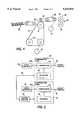
- FIG. 1is an exploded view illustrating the principal mechanical components incorporating the present invention
- FIG. 2is a block diagram depicting the major control elements of the components shown in FIG. 1;
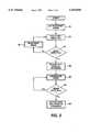
- FIG. 3is a flow chart the drive control reference set up in accordance with the present invention.
- FIGS. 1there is shown a photoreceptor surface 12 wrapped over supporting rolls, 16, and 18 and driven by a first servo system 20.
- a developed toner image on photoreceptor surface 12is transferred to a copy sheet 24 suitably supplied from a copy sheet source 26.
- the copy sheet 24is then immediately stripped from the photoreceptor surface 12 for engagement by a prefuser transport 28 to be delivered to fuser 30 for permanently fixing the toner image to the copy sheet.
- fuser 30includes a heated fuser roller 34 and a pressure roller 36 with the powder image on the copy sheet contacting fuser roller 34.
- a suitable sensor 35detects the absence or presence of a copy sheet leaving fuser 30 and the copy sheets are then advanced to an appropriate not shown output tray or finishing station.
- the prefuser transport 28is driven by a second servo system 32 and the stress or tension placed upon the copy sheet 24 when overlapping both roll 16 and prefuser transport 28 is a function of the speed of the photoreceptor surface at roll 16 and the speed of the prefuser transport.
- the relative speed of the photoreceptor surface at roll 16 and the speed of the prefuser transport 28is, in turn, a function of the power delivered to the photoreceptor surface by the first servo system and the power delivered to the prefuser transport by the second servo system.
- the speed of the prefused transport 28is greater than the speed of the photoreceptor surface at roll 16, then there will be a tendency for the prefuser transport to pull the copy sheet away from the photoreceptor surface at roll 16.
- the speed of the prefuser transport 28is less than the speed of the photoreceptor surface at roll 16, there will be a tendency of the photoreceptor surface at roll 16 to push the copy sheet ahead of the prefuser transport 28, often times causing the sheet to warp or buckle. In either case, smudging or other degradation of the developed image on the copy sheet will occur to the detriment of the quality of the finished product.
- a motor or drive speed sensor 40 disposed adjacent the roll 16determines the velocity or speed of the photoreceptor 12 at roll 16.
- a suitable signal 40Ais conveyed from the speed sensor to compensate or logic generally shown at 42 including comparator 44 and a reference signal 46 to be further described with reference to FIG. 3.
- the comparator 44responds to the input signal 40a from speed sensor 40 and the reference signal 46 to provide a signal 48 to adjust servo system 20 to control the speed of the photoreceptor surface 12.
- speed sensor 50 disposed adjacent the prefuser transport 28determines the surface velocity or speed of the prefuser transport and provides a signal 50a to compensator logic 52 including comparator 54 and reference signal 56.
- the comparator 54responds to the input signal 50a from the speed sensor 50 and a reference signal 56 to provide a servo system adjust signal 58 to adjust servo system 32 controlling the speed of the prefuser transport 28.
- Both the compensator logic 42 and compensator logic 52are interconnected to master control 60 via a two way communication link illustrated at 62.
- Speed sensors 40 and 50are any suitable speed sensing devices such as an optical disc mounted on the moving element or the motor shaft and a stationary light source and photodetector to record the number of received signals or pulses per given time period.
- a reference signalin particular reference signal 56 for servo system 32.
- the speed of the prefuser transport 28is set at a given value as shown at block 70.
- Block 72there is a check for sheet pull.
- Sheet pull at the prefuser transportcan be determined by sensing a lower demand for power at the photoreceptor surface servo system 20. That is, assuming that the prefuser transport 28 and the photoreceptor surface 12 were travelling at the same surface speed, there would be a smooth flow of the copy sheet 24 between the photoreceptor surface and the prefuser transport.
- the prefuser transport 28tends to pull the copy sheet from the photoreceptor surface.
- This external power to pull the copy sheet away from the photoreceptor surfaceis sensed by the servo system 20 as an indication of less power required at servo system 20 to deliver the copy sheet 24.
- the determination of the copy sheet pull by the prefuser transportcan be determined by a sensed power change at the compensator logic 42 of servo system 20 controlling the movement of the photoreceptor surface 12.
- decision block 74there is a determination of whether or not there is a sensed sheet pull. If not, the speed of the prefuser transport is incremented as shown at 76 to again check for sheet pull at 72. This process is repeated until the speed of the prefuser transport has increased to a sufficient speed to sense a copy sheet pull at the prefuser transport. Upon detection of a copy sheet pull, the pull speed reference is determined as shown at block 78.
- the precise point or speed of the prefuser transport in which a no pull condition is sensedis determined by decreasing the speed of the prefuser transport 28 from the speed at the pull condition.
- the speedis incrementally decreased and at each decreased increment a determination is made whether or not there is a sheet pull as illustrated at decision block 82.
- a sensed condition of no pullis determined by the speed of the photoreceptor surface at roll 16 at a speed sufficient to keep up with the speed of the prefuser transport. This condition is a function of the power delivered by the photoreceptor servo system 20 to drive the photoreceptor surface 12 at roll 16.
- this speedis likewise reported as a reference speed as illustrated at block 84.
- adjustmentcan be made by slowing down the surface speed of one of the servo systems via the compensator or adjustment logic or speeding up the other surface driven by the second servo system, or any combination of speed adjustment of both of the servo systems through suitable compensator logic to synchronize the speed of a copy sheet moving from one drive system to another drive system.
- the outputs of the digital compensatorscan be monitored at the time of a transition of a copy sheet or other document from one transport to another transport to detect any mismatch of surface velocity. Once the velocity mismatch is detected, a servo system reference can be adjusted through a suitable command channel to a master control to correct for the surface velocity mismatch.
Landscapes
- Physics & Mathematics (AREA)
- General Physics & Mathematics (AREA)
- Control Or Security For Electrophotography (AREA)
Abstract
Description
Claims (7)
Priority Applications (2)
| Application Number | Priority Date | Filing Date | Title |
|---|---|---|---|
| US08/276,376US5543894A (en) | 1994-07-18 | 1994-07-18 | Correction for surface velocity mismatch in multiple servo paper paths |
| JP7179107AJPH0844267A (en) | 1994-07-18 | 1995-07-14 | Copying machine |
Applications Claiming Priority (1)
| Application Number | Priority Date | Filing Date | Title |
|---|---|---|---|
| US08/276,376US5543894A (en) | 1994-07-18 | 1994-07-18 | Correction for surface velocity mismatch in multiple servo paper paths |
Publications (1)
| Publication Number | Publication Date |
|---|---|
| US5543894Atrue US5543894A (en) | 1996-08-06 |
Family
ID=23056419
Family Applications (1)
| Application Number | Title | Priority Date | Filing Date |
|---|---|---|---|
| US08/276,376Expired - LifetimeUS5543894A (en) | 1994-07-18 | 1994-07-18 | Correction for surface velocity mismatch in multiple servo paper paths |
Country Status (2)
| Country | Link |
|---|---|
| US (1) | US5543894A (en) |
| JP (1) | JPH0844267A (en) |
Cited By (13)
| Publication number | Priority date | Publication date | Assignee | Title |
|---|---|---|---|---|
| US6002890A (en)* | 1998-09-28 | 1999-12-14 | Xerox Corporation | Feedback between marking and paper path subsystems to reduce shutdowns |
| WO2002035292A1 (en)* | 2000-10-20 | 2002-05-02 | Schott Glas | Printing machine with adjusting device for synchronizing the photoconductor and feed guides by means of a master-slave controller |
| US6456808B1 (en)* | 2001-03-07 | 2002-09-24 | Hewlett-Packard Company | Systems and methods for reducing banding artifact in electrophotographic devices using drum velocity control |
| US20030054022A1 (en)* | 1999-12-22 | 2003-03-20 | Acell, Inc. | Tissue regenerative composition, method of making, and method of use thereof |
| US6579538B1 (en) | 1999-12-22 | 2003-06-17 | Acell, Inc. | Tissue regenerative compositions for cardiac applications, method of making, and method of use thereof |
| US20040043006A1 (en)* | 2002-08-27 | 2004-03-04 | Badylak Stephen F. | Tissue regenerative composition |
| US20040176855A1 (en)* | 2003-03-07 | 2004-09-09 | Acell, Inc. | Decellularized liver for repair of tissue and treatment of organ deficiency |
| US20040175366A1 (en)* | 2003-03-07 | 2004-09-09 | Acell, Inc. | Scaffold for cell growth and differentiation |
| US20040251589A1 (en)* | 2003-03-11 | 2004-12-16 | Tohoku Ricoh Co., Ltd. | Bulk paper feeding device with intermediate conveyor for image forming device |
| US20050025838A1 (en)* | 2003-06-25 | 2005-02-03 | Badylak Stephen F. | Conditioned compositions for tissue restoration |
| US20050046814A1 (en)* | 2003-08-28 | 2005-03-03 | Xerox Corporation | Automatic fuser control |
| US20070231006A1 (en)* | 2006-03-30 | 2007-10-04 | Lexmark International, Inc. | Gear train backlash removal during component acceleration in an image forming device |
| US20090281734A1 (en)* | 2008-05-12 | 2009-11-12 | Xerox Corporation | Determining real-time performance of a sub-assembly driven by a dc motor |
Citations (6)
| Publication number | Priority date | Publication date | Assignee | Title |
|---|---|---|---|---|
| US4541709A (en)* | 1983-02-04 | 1985-09-17 | Oce-Nederland B.V. | Image transfer apparatus |
| US4928141A (en)* | 1989-02-22 | 1990-05-22 | Xerox Corporation | Buckle control for reducing interactions between media drive systems |
| US4947209A (en)* | 1988-05-18 | 1990-08-07 | Shinko Electric Co., Ltd. | Copying machine control apparatus |
| US5086319A (en)* | 1989-11-17 | 1992-02-04 | Xerox Corporation | Multiple servo system for compensation of document mis-registration |
| US5130748A (en)* | 1986-09-11 | 1992-07-14 | Fuji Xerox Co., Ltd. | Control unit of copying machines |
| US5235392A (en)* | 1992-06-08 | 1993-08-10 | Eastman Kodak Comany | Reproduction apparatus having image transfer velocity matching means |
- 1994
- 1994-07-18USUS08/276,376patent/US5543894A/ennot_activeExpired - Lifetime
- 1995
- 1995-07-14JPJP7179107Apatent/JPH0844267A/enactivePending
Patent Citations (6)
| Publication number | Priority date | Publication date | Assignee | Title |
|---|---|---|---|---|
| US4541709A (en)* | 1983-02-04 | 1985-09-17 | Oce-Nederland B.V. | Image transfer apparatus |
| US5130748A (en)* | 1986-09-11 | 1992-07-14 | Fuji Xerox Co., Ltd. | Control unit of copying machines |
| US4947209A (en)* | 1988-05-18 | 1990-08-07 | Shinko Electric Co., Ltd. | Copying machine control apparatus |
| US4928141A (en)* | 1989-02-22 | 1990-05-22 | Xerox Corporation | Buckle control for reducing interactions between media drive systems |
| US5086319A (en)* | 1989-11-17 | 1992-02-04 | Xerox Corporation | Multiple servo system for compensation of document mis-registration |
| US5235392A (en)* | 1992-06-08 | 1993-08-10 | Eastman Kodak Comany | Reproduction apparatus having image transfer velocity matching means |
Cited By (46)
| Publication number | Priority date | Publication date | Assignee | Title |
|---|---|---|---|---|
| US6002890A (en)* | 1998-09-28 | 1999-12-14 | Xerox Corporation | Feedback between marking and paper path subsystems to reduce shutdowns |
| US6887495B2 (en) | 1999-12-22 | 2005-05-03 | Acell, Inc. | Tissue regenerative composition, method of making, and method of use thereof |
| US6890562B2 (en) | 1999-12-22 | 2005-05-10 | Acell, Inc. | Tissue regenerative composition, method of making, and method of use thereof |
| US20030054022A1 (en)* | 1999-12-22 | 2003-03-20 | Acell, Inc. | Tissue regenerative composition, method of making, and method of use thereof |
| US20030059411A1 (en)* | 1999-12-22 | 2003-03-27 | Acell, Inc. | Tissue regenerative composition, method of making, and method of use thereof |
| US20030059409A1 (en)* | 1999-12-22 | 2003-03-27 | Acell, Inc. | Tissue regenerative composition, method of making, and method of use thereof |
| US6849273B2 (en) | 1999-12-22 | 2005-02-01 | Acell, Inc. | Tissue regenerative composition, method of making, and method of use thereof |
| US20030059407A1 (en)* | 1999-12-22 | 2003-03-27 | Acell, Inc. | Tissue regenerative composition, method of making, and method of use thereof |
| US20030059404A1 (en)* | 1999-12-22 | 2003-03-27 | Acell, Inc. | Tissue regenerative composition, method of making , and method of use thereof |
| US20030059405A1 (en)* | 1999-12-22 | 2003-03-27 | Acell, Inc. | Tissue regenerative composition, method of making, and method of use thereof |
| US20030064112A1 (en)* | 1999-12-22 | 2003-04-03 | Acell, Inc. | Tissue regenerative composition, method of making, and method of use thereof |
| US20030064111A1 (en)* | 1999-12-22 | 2003-04-03 | Acell, Inc. | Tissue regenerative composition, method of making, and method of use thereof |
| US6576265B1 (en) | 1999-12-22 | 2003-06-10 | Acell, Inc. | Tissue regenerative composition, method of making, and method of use thereof |
| US6579538B1 (en) | 1999-12-22 | 2003-06-17 | Acell, Inc. | Tissue regenerative compositions for cardiac applications, method of making, and method of use thereof |
| US9265860B2 (en) | 1999-12-22 | 2016-02-23 | Acell, Inc. | Tissue regenerative composition, method of making, and method of use thereof |
| US9433701B2 (en) | 1999-12-22 | 2016-09-06 | Acell, Inc. | Extracellular matrix for the treatment of intestinal disease and methods thereof |
| US6783776B2 (en) | 1999-12-22 | 2004-08-31 | Acell, Inc. | Tissue regenerative composition, method of making, and method of use thereof |
| US6893666B2 (en) | 1999-12-22 | 2005-05-17 | Acell, Inc. | Tissue regenerative composition, method of making, and method of use thereof |
| US6890564B2 (en) | 1999-12-22 | 2005-05-10 | Acell, Inc. | Tissue regenerative composition, method of making, and method of use thereof |
| US6890563B2 (en) | 1999-12-22 | 2005-05-10 | Acell, Inc. | Tissue regenerative composition, method of making, and method of use thereof |
| US6869619B2 (en) | 1999-12-22 | 2005-03-22 | Acell, Inc. | Tissue regenerative composition, method of making, and method of use thereof |
| US20030059410A1 (en)* | 1999-12-22 | 2003-03-27 | Acell, Inc. | Tissue regenerative composition, method of making, and method of use thereof |
| US10092678B2 (en) | 1999-12-22 | 2018-10-09 | Acell, Inc. | Extracellular matrix for the treatment of intestinal disease and methods thereof |
| US6852339B2 (en) | 1999-12-22 | 2005-02-08 | Acell, Inc. | Tissue regenerative composition, method of making, and method of use thereof |
| US6861074B2 (en) | 1999-12-22 | 2005-03-01 | Acell, Inc. | Tissue regenerative composition, method of making, and method of use thereof |
| US20040028444A1 (en)* | 2000-10-20 | 2004-02-12 | Bernd Schultheis | Printing machine with adjusting device for synchronizing the photoconductor and feed guides by means of a master-slave controller |
| WO2002035292A1 (en)* | 2000-10-20 | 2002-05-02 | Schott Glas | Printing machine with adjusting device for synchronizing the photoconductor and feed guides by means of a master-slave controller |
| US6810799B2 (en)* | 2000-10-20 | 2004-11-02 | Schott Glas | Printing machine with adjusting device for synchronizing the photoconductor and feed guides by means of a master-slave controller |
| US6456808B1 (en)* | 2001-03-07 | 2002-09-24 | Hewlett-Packard Company | Systems and methods for reducing banding artifact in electrophotographic devices using drum velocity control |
| US20040043006A1 (en)* | 2002-08-27 | 2004-03-04 | Badylak Stephen F. | Tissue regenerative composition |
| US20110097378A1 (en)* | 2003-03-07 | 2011-04-28 | Badylak Stephen F | Decellularized liver for repair of tissue and treatment of organ deficiency |
| US20040175366A1 (en)* | 2003-03-07 | 2004-09-09 | Acell, Inc. | Scaffold for cell growth and differentiation |
| US20100119579A1 (en)* | 2003-03-07 | 2010-05-13 | Badylak Stephen F | Decellularized liver for repair of tissue and treatment of organ deficiency |
| US20080058956A1 (en)* | 2003-03-07 | 2008-03-06 | Badylak Stephen F | Decellularized liver for repair of tissue and treatment of organ deficiency |
| US20040176855A1 (en)* | 2003-03-07 | 2004-09-09 | Acell, Inc. | Decellularized liver for repair of tissue and treatment of organ deficiency |
| US20100297212A1 (en)* | 2003-03-07 | 2010-11-25 | Badylak Stephen F | Scaffold for cell growth and differentiation |
| US20040251589A1 (en)* | 2003-03-11 | 2004-12-16 | Tohoku Ricoh Co., Ltd. | Bulk paper feeding device with intermediate conveyor for image forming device |
| US7308853B2 (en)* | 2003-03-11 | 2007-12-18 | Tohoku Ricoh Co., Ltd. | Bulk paper feeding device with intermediate conveyor for image forming device |
| US20050025838A1 (en)* | 2003-06-25 | 2005-02-03 | Badylak Stephen F. | Conditioned compositions for tissue restoration |
| US8409625B2 (en) | 2003-06-25 | 2013-04-02 | Acell, Inc. | Conditioned decellularized native tissues for tissue restoration |
| US6982781B2 (en) | 2003-08-28 | 2006-01-03 | Xerox Corporation | Automatic fuser control |
| US20050046814A1 (en)* | 2003-08-28 | 2005-03-03 | Xerox Corporation | Automatic fuser control |
| US7522863B2 (en) | 2006-03-30 | 2009-04-21 | Lexmark International, Inc. | Gear train backlash removal during component acceleration in an image forming device |
| US20070231006A1 (en)* | 2006-03-30 | 2007-10-04 | Lexmark International, Inc. | Gear train backlash removal during component acceleration in an image forming device |
| US7835887B2 (en) | 2008-05-12 | 2010-11-16 | Xerox Corporation | Determining real-time performance of a sub-assembly driven by a DC motor |
| US20090281734A1 (en)* | 2008-05-12 | 2009-11-12 | Xerox Corporation | Determining real-time performance of a sub-assembly driven by a dc motor |
Also Published As
| Publication number | Publication date |
|---|---|
| JPH0844267A (en) | 1996-02-16 |
Similar Documents
| Publication | Publication Date | Title |
|---|---|---|
| US5543894A (en) | Correction for surface velocity mismatch in multiple servo paper paths | |
| US4941021A (en) | Image forming apparatus with recording material loop forming and control means | |
| US6374075B1 (en) | Printing systems and methods | |
| US8660473B2 (en) | Intermediate transfer device, image forming apparatus and secondary transfer method | |
| US6014542A (en) | Image formation system | |
| US5502544A (en) | Parameter based digital servo controller | |
| US7634208B2 (en) | Driving device, image forming apparatus including driving device, and control method therefor | |
| US8000622B2 (en) | Moving body controlling device, intermediate transferring device, and image forming apparatus having the same | |
| US4928141A (en) | Buckle control for reducing interactions between media drive systems | |
| US20060193665A1 (en) | Method for image forming capable of performing fast and stable sheet transfer operations | |
| US8955439B2 (en) | Printing system and printing apparatus using continuous recording sheet, and conveyance control method of continuous recording sheet | |
| US5471290A (en) | Image forming apparatus | |
| JP2017198786A (en) | Image forming apparatus and program | |
| US5331384A (en) | Fixing apparatus having temperature controller which controls temperature according to width size and number of recording sheets | |
| US5920759A (en) | Sheet curl correcting mechanism and image forming apparatus having the mechanism | |
| EP0940730B1 (en) | Hybrid hierarchical control architecture for media handling | |
| EP1486833B1 (en) | Transfer roll engagement method for minimizing motion quality disturbances | |
| EP2042935B1 (en) | Image forming apparatus | |
| JP2000089605A (en) | Fixing device for image forming device | |
| US20080285988A1 (en) | Image forming apparatus and recording-medium feeding method | |
| US7054571B2 (en) | Method of driving a fuser roll in an electrophotographic printer | |
| US6002890A (en) | Feedback between marking and paper path subsystems to reduce shutdowns | |
| US11144002B2 (en) | Image forming apparatus and conveyance control method | |
| JPH10161441A (en) | Image forming device | |
| US5938191A (en) | Segmented drive roll for exit nip prior to exit trays |
Legal Events
| Date | Code | Title | Description |
|---|---|---|---|
| AS | Assignment | Owner name:XEROX CORPORATION, CONNECTICUT Free format text:ASSIGNMENT OF ASSIGNORS INTEREST;ASSIGNOR:CAROLAN, KEVIN M.;REEL/FRAME:007098/0537 Effective date:19940712 | |
| STCF | Information on status: patent grant | Free format text:PATENTED CASE | |
| FPAY | Fee payment | Year of fee payment:4 | |
| AS | Assignment | Owner name:BANK ONE, NA, AS ADMINISTRATIVE AGENT, ILLINOIS Free format text:SECURITY INTEREST;ASSIGNOR:XEROX CORPORATION;REEL/FRAME:013153/0001 Effective date:20020621 | |
| AS | Assignment | Owner name:JPMORGAN CHASE BANK, AS COLLATERAL AGENT, TEXAS Free format text:SECURITY AGREEMENT;ASSIGNOR:XEROX CORPORATION;REEL/FRAME:015134/0476 Effective date:20030625 Owner name:JPMORGAN CHASE BANK, AS COLLATERAL AGENT,TEXAS Free format text:SECURITY AGREEMENT;ASSIGNOR:XEROX CORPORATION;REEL/FRAME:015134/0476 Effective date:20030625 | |
| FPAY | Fee payment | Year of fee payment:8 | |
| FPAY | Fee payment | Year of fee payment:12 | |
| AS | Assignment | Owner name:XEROX CORPORATION, CONNECTICUT Free format text:RELEASE BY SECURED PARTY;ASSIGNOR:JPMORGAN CHASE BANK, N.A. AS SUCCESSOR-IN-INTEREST ADMINISTRATIVE AGENT AND COLLATERAL AGENT TO JPMORGAN CHASE BANK;REEL/FRAME:066728/0193 Effective date:20220822 |