US5543816A - Head mounted display system with aspheric optics - Google Patents
Head mounted display system with aspheric opticsDownload PDFInfo
- Publication number
- US5543816A US5543816AUS08/155,429US15542993AUS5543816AUS 5543816 AUS5543816 AUS 5543816AUS 15542993 AUS15542993 AUS 15542993AUS 5543816 AUS5543816 AUS 5543816A
- Authority
- US
- United States
- Prior art keywords
- eye
- user
- lens
- display system
- support
- Prior art date
- Legal status (The legal status is an assumption and is not a legal conclusion. Google has not performed a legal analysis and makes no representation as to the accuracy of the status listed.)
- Expired - Fee Related
Links
Images

Classifications
- G—PHYSICS
- G02—OPTICS
- G02B—OPTICAL ELEMENTS, SYSTEMS OR APPARATUS
- G02B27/00—Optical systems or apparatus not provided for by any of the groups G02B1/00 - G02B26/00, G02B30/00
- G02B27/01—Head-up displays
- G02B27/017—Head mounted
- G02B27/0172—Head mounted characterised by optical features
- G—PHYSICS
- G02—OPTICS
- G02B—OPTICAL ELEMENTS, SYSTEMS OR APPARATUS
- G02B13/00—Optical objectives specially designed for the purposes specified below
- G02B13/18—Optical objectives specially designed for the purposes specified below with lenses having one or more non-spherical faces, e.g. for reducing geometrical aberration
- G—PHYSICS
- G02—OPTICS
- G02B—OPTICAL ELEMENTS, SYSTEMS OR APPARATUS
- G02B30/00—Optical systems or apparatus for producing three-dimensional [3D] effects, e.g. stereoscopic images
- G02B30/20—Optical systems or apparatus for producing three-dimensional [3D] effects, e.g. stereoscopic images by providing first and second parallax images to an observer's left and right eyes
- G02B30/34—Stereoscopes providing a stereoscopic pair of separated images corresponding to parallactically displaced views of the same object, e.g. 3D slide viewers
- G—PHYSICS
- G02—OPTICS
- G02B—OPTICAL ELEMENTS, SYSTEMS OR APPARATUS
- G02B27/00—Optical systems or apparatus not provided for by any of the groups G02B1/00 - G02B26/00, G02B30/00
- G02B27/01—Head-up displays
- G02B27/0101—Head-up displays characterised by optical features
- G02B2027/011—Head-up displays characterised by optical features comprising device for correcting geometrical aberrations, distortion
- G—PHYSICS
- G02—OPTICS
- G02B—OPTICAL ELEMENTS, SYSTEMS OR APPARATUS
- G02B27/00—Optical systems or apparatus not provided for by any of the groups G02B1/00 - G02B26/00, G02B30/00
- G02B27/01—Head-up displays
- G02B27/0101—Head-up displays characterised by optical features
- G02B2027/0127—Head-up displays characterised by optical features comprising devices increasing the depth of field
- G—PHYSICS
- G02—OPTICS
- G02B—OPTICAL ELEMENTS, SYSTEMS OR APPARATUS
- G02B27/00—Optical systems or apparatus not provided for by any of the groups G02B1/00 - G02B26/00, G02B30/00
- G02B27/01—Head-up displays
- G02B27/0101—Head-up displays characterised by optical features
- G02B2027/0132—Head-up displays characterised by optical features comprising binocular systems
- G—PHYSICS
- G02—OPTICS
- G02B—OPTICAL ELEMENTS, SYSTEMS OR APPARATUS
- G02B27/00—Optical systems or apparatus not provided for by any of the groups G02B1/00 - G02B26/00, G02B30/00
- G02B27/01—Head-up displays
- G02B27/0149—Head-up displays characterised by mechanical features
- G02B2027/0154—Head-up displays characterised by mechanical features with movable elements
- G—PHYSICS
- G02—OPTICS
- G02B—OPTICAL ELEMENTS, SYSTEMS OR APPARATUS
- G02B27/00—Optical systems or apparatus not provided for by any of the groups G02B1/00 - G02B26/00, G02B30/00
- G02B27/01—Head-up displays
- G02B27/017—Head mounted
- G02B2027/0178—Eyeglass type
- G—PHYSICS
- G02—OPTICS
- G02B—OPTICAL ELEMENTS, SYSTEMS OR APPARATUS
- G02B27/00—Optical systems or apparatus not provided for by any of the groups G02B1/00 - G02B26/00, G02B30/00
- G02B27/01—Head-up displays
- G02B27/017—Head mounted
Definitions
- the present inventionis directed to a head mounted display system and more particularly to a head mounted display system that employs a compact, optical system with an aspheric lens for minimizing distortions across the virtual image projected by the system.
- Head mounted display systemsare known that include a lens disposed between an eye of the user and the face of a display for projecting an enlarged virtual image of the displayed information. These systems, however, typically employ a lens with a simple curvature such as a spherical lens.
- the virtual image that results with the use of a spherical lenshas a number of distortions, including variations in the magnification and field of curvature across the image as well as edge distortions such as barrel distortion.
- compensating lenses and the likeare typically added to the optical system.
- additional opticsincrease the weight and overall size of the optical system. It is important to minimize the weight and size of the optical system for a head mounted display unit, otherwise the unit is too heavy and cumbersome to be comfortably supported on a user's head.
- the head mounted display system of the present inventionutilizes an aspheric lens that controls the distance from the user at which the virtual image appears and that further substantially eliminates distortions across the virtual image.
- the head mounted display system of the present inventionincludes a support to mount the display system on a user's head.
- An image sourceis mounted on the support to provide video information.
- the aspheric lensis mounted on the support relative to the image source to allow a user to view, through the aspheric lens, an enlarged image of the video with the image being projected at a distance from the user.
- the aspheric lenshas a surface shaped with a number of concentric zones that includes an inner-zone for substantially controlling the distance from the user at which the virtual image appears and one or more zones located outside of the inner-zone to minimize distortions across the virtual image.
- a mid-zoneminimizes variations in magnification and field of curvature across the virtual image and an outer-zone minimizes distortions about the edges of the virtual image.
- the aspheric lensmay include a single aspheric surface as described above.
- the aspheric lensmay be biaspheric, including an aspheric entrance surface and an aspheric exit surface.
- the aspheric lensmay be formed of at least two materials having different indices of refraction so as to form an achromat to compensate for chromatic aberrations.
- the aspheric lensin accordance with the present invention, may be utilized in a monocular head mounted display system.
- two aspheric lensesone associated with the user's right eye and one associated with the user's left eye, may be employed with a single display or a pair of displays or image sources so as to provide a binocular head mounted display system.
- the aspheric lens and displayare mounted on the support such that the lens is substantially parallel to the face of the display, wherein a central axis of the lens extends perpendicular to the face of the display.
- the aspheric lens and displayare mounted on the support at a convergence angle with respect to the axis of a user's eye when looking straight ahead.
- the lens and displayare at a convergence angle with respect to the user's eye to direct the user's eye inward at an angle that is natural for a user viewing an object at a distance that is less than infinity.
- the aspheric lens and displayare further mounted on the support relative to one another such that the distance between the lens and display is variable.
- the distance between the right-eye lens and display and the distance between the left-eye lens and displayare independently variable. Because the distances between the lens and display are independently variable for the user's right and left eye, the distance of each lens may be set by a particular user so as to accommodate for refractive error in user's that are near-sighted or far-sighted.
- the head mounted display system of the present inventionmay be worn by a user who normally wears corrective eyewear, without that eyewear.
- the support on which the optics and display(s) are mountedis movable with respect to the user's face to allow a user to vary the distance between the user's eyes and respective lenses together.
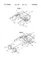
- FIG. 1is a perspective back view of the head mounted display system in accordance with the present invention
- FIG. 2is an exploded, perspective back view of the head mounted display system depicted in FIG. 1;
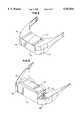
- FIG. 3is an exploded front perspective front view of the head mounted display system of FIG. 1;
- FIG. 4is a front perspective view of the head mounted display system of FIG. 1;
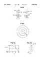
- FIG. 5is a schematic illustration of the orientation of the displays and optics of the system shown in FIG. 1 relative to a user's eye;
- FIG. 6is a schematic illustration of an aspheric lens with three concentric zones.
- FIGS. 7A and 7Bare graphs illustrating how one aspheric surface of the lens varies with X;
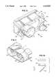
- FIG. 8is a front perspective view of a head mounted display system in accordance with the present invention utilizing a different support to mount the system on a user's head;
- FIG. 9is a partial front perspective view of the head mounted display system shown in FIG. 8;
- FIG. 10is a back perspective view of a rotatable mounting and a laterally moveable mounting for the lens and display pairs of the system of FIG. 8;
- FIG. 11is a back perspective view of the laterally moveable mounting for the lens and display pairs of the system of FIG. 8;
- FIG. 12is a schematic illustration of an alternative embodiment of the optical system utilizing an aspheric lens in accordance with the present invention.
- the head mounted display unit 10 of the present inventionincludes a frame 12 having a support 14 for the optical system.
- the support 14includes a front cover 15 and is adjustably mounted on a pair of temples 16 and 18.
- the optical system of the head mounted display unit 10includes a right-eye aspheric lens 20 and a left-eye aspheric lens 22 into which a user looks to view an enlarged virtual image of the video information depicted on respective displays 24 and 26 where the virtual image appears at a distance from the user that is greater than the actual distance of the display from the user.
- the displays 24 and 26may be liquid crystal displays or the like which are mounted on the support 14 such that the face 25, 27 of each display 24, 26 is aligned with a respective aperture 29, 31 in the support 14 with the face 25, 27 of each display 24, 26 being directed towards the user.
- the frame 12also supports drive electronics for the displays 24 and 26, as well as for a pair of earphones 33 and 35.
- the drive electronics for the displaysare responsive to standard video input signals to drive the displays to depict video information.
- the video input signal generatoris preferably a separate, remote unit.
- the video input signal generatormay take the form of a television tuner, video camera, video player, video game, computer, or other device that generates a video input signal.
- the displays 24 and 26may be driven to provide a stereoscopic virtual image, as is well known.
- the head mounted display system 10may be coupled to the video input signal generator and/or audio generator by a cable or the like; however, the unit 10 need not be physically connected to the video/audio input signal generator.
- the video and audio input signalsmay be RF modulated and transmitted from the remote unit to a head mounted display unit 10 that includes an RF receiver, as described in detailed in U.S. patent application Ser. No. 07/986,422, filed Dec. 4, 1992, assigned to the Assignee of the present invention and incorporated herein by reference.
- Each of the aspheric lenses 20 and 22, as shown in FIG. 6includes a surface shaped with a number of concentric zones I, II and III so as to map a flat displayed video image onto the complex curvature of the user's retina so that the virtual image appears without distortions therein.
- the inner-zone Iis substantially spherical and primarily controls the distance from the user at which the virtual image appears, i.e., the focal length of the lens 20, 22.
- a mid-zone IIis flatter in radius than the inner-zone I and minimizes variations in magnification and field of curvature across the virtual image.
- An outer-zone IIIis shaped so as to minimize distortions in the edges of the virtual image so that the edges appear straight and each edge appears to be at right angles with respect to its adjacent edge.
- each lens 20, 22is designed in accordance with the following equation: ##EQU1## where X represents sag and Y describes the surface of the asphere as a function of X as shown in FIGS. 7A and 7B.
- Rrepresents the central radius of curvature of the lens 20, 22 and C is equal to 1/R.
- R and Care the predominant factors which characterize the inner-zone I.
- the constant, cc, which represents the conic constantis the predominant factor controlling the surface of the aspheric lens in the mid-zone II; whereas the constants A2, A4 and A6 are the predominant factors in controlling the curvature in the outer-zone III.
- Each of the aspheric lenses 20, 22may be formed as a biasphere having an aspheric entrance surface adjacent the display and an aspheric exit surface adjacent the user's eye.
- Each aspheric lens 20, 22may be formed of a single, optically transmissive material with an index of refraction of approximately 1.49 although materials with other indices of refraction may be used as well. It is noted that as the index of refraction of the material increases, the radius of curvature of the aspheric surface(s) flattens.
- each aspheric lens 20, 22may be formed of at least two materials having different indices of refraction so as to form an achromat to compensate for chromatic aberrations.
- the constants for the above-identified equation which describe the entrance surface of the lensare as follows:
- the constants describing the exit surface of the lens for 1X magnificationare as follows:
- an equivalent lens 20, 22may be formed by decreasing the power of one surface and increasing the power of the opposite surface. Further, although not necessary, it is preferred that the entrance surface of the lens 20, 22 is formed with more power than the exit surface.
- the use of a single aspheric lens 20, 22 in each optical path of the systemallows the head mounted display unit 10 to be very lightweight and compact.
- the distance from the cover 15 to a back 60 of the support 14 representing the thickness of the optical systemis merely 2 inches.
- the optical systemis small and compact, the virtual image seen by a user is substantially without distortions therein across the entire width of the image.
- Each of the lenses 20, 22is mounted in a respective lens holder 28, 30 that is movably mounted on the support 14 in a respective, generally cylindrical aperture 32, 34.
- Protrusions 38 and 39are positioned opposite to each other on the inner surface of the wall defining the aperture 32.
- the protrusions 38 and 39engage a helical groove 36 formed about the outer cylindrical surface of the lens holder 36 so that as the lens holder 36 is rotated in the aperture 32, the pins 38 and 39 engaging the groove 28 move the lens 20 closer to the display 24 or farther therefrom while maintaining the central axis of the lens 20 perpendicular to the face 25 of the display 24 such that the display face 25 is generally parallel to the aspheric lens 20.
- An aperture 43is formed in the wall of the support 14 adjacent the lens holder 28 so that a user can manually engage the lens holder 28 to rotate the lens 20.
- protrusions 40 and 41are positioned opposite to each other on the inner surface of the wall defining the aperture 34.
- the protrusions 40 and 41engage a helical groove 37 formed about the outer cylindrical surface of the lens holder 30 so that as the lens holder 30 is rotated in the aperture 34, the pins 40 and 41 engaging the groove 37 move the lens 22 closer to the display 26 or farther therefrom while maintaining the central axis of the lens 22 perpendicular to the face 27 of the display 26 such that the display face 27 is generally parallel to the aspheric lens 22.
- An aperture 45is formed in the wall of the support 14 adjacent the lens holder 30 so that a user can manually engage the lens holder 30 to rotate the lens 22.
- the cylindrical apertures 32 and 34 of the support 14are formed therein such that the axes of the apertures 32, 34 are converging towards the displays. Therefore, if the central axis of each of the lenses 20, 22 extends from the center of the lens 20, 22 to the center of the respective display 24, 26, the centers of the displays 24 and 26 will be closer than the centers of the aspheric lenses 20 and 22 as shown in FIG. 5. This convergence angle 8 is small, so as to direct a user's eye inward from the axis of the eye when looking straight ahead.
- the user's eyesare directed inward at a natural angle to the location of the virtual image at a distance that is less than infinity from the user. For example, for a virtual image that is to appear two-ten feet from the user, a convergence angle of approximately 2°-4° is desired.
- the head mounted display system 10 of the present inventionaccommodates users having various interpupillary distances by allowing the support 14 for the optical system to be moved as an integral unit closer to the user's eyes in a direction 50 or farther away therefrom in a direction 52 as depicted in FIG. 4.
- each of the temples 16 and 18is formed with a respective slot 54 through which a screw 56 extends so that the screw 56 can be screwed into a threaded aperture in the outer surface of a flange 58 of the support 14.
- the support 14may be moved towards or away from the user's face to vary the distance between the optical system and the user's eyes to thereby correct for the user's individual interpupillary distance.
- each of the aspheric lenses 20, 22is also independently movable with respect to the displays 24 and 26, the lenses may be individually moved towards or away from the displays so as to accommodate for refractive error in each of the user's eyes for users that are near-sighted or far-sighted.
- the head mounted display system of the present inventionmay be worn by a user who normally wears corrective eyewear, without that eyewear.
- FIGS. 8-11illustrate another embodiment of the frame for a slightly modified support 14' of the optical system that allows the support 14' to be rotated as well as to be moved along a linear path towards and away from the user's eyes.
- the support 14'is formed without the flanges 58 depicted in FIGS. 1-4.
- the support 14'is slidably mounted in a housing 70 that is in turn rotatably mounted on a frame 72.
- the frame 72When the frame 72 is worn on a user's head, the frame 72 may be positioned such that the lenses 20 and 22 as well as the respective displays 24 and 26 are positioned directly in front of the user's eyes. Alternatively, the frame 72 may be worn higher on the user's head so that the user looks slightly up to view the virtual image.
- the housing 70is rotatable in the frame 72 so that the user can align his eyes with the central axis of the respective lenses 20, 22. It is noted that even if the frame 72 is worn such that the lenses 20, 22 are positioned directly in front of the user's eyes, the housing 70 may be rotated on the frame 72 slightly so as to accommodate various users and to allow them to easily align the central axis of each lens 20, 22 with their eyes.
- the housing 70is formed with a cylindrical protrusion 74 and 76 extending from opposite sides 78 and 80 of the housing 70.
- the protrusions 74 and 76extend into respective apertures 82 formed in the frame 72 so that the protrusions can rotate therein.
- the lower portion of each aperture 82is formed in a respective bottom cover 86 and 88 of the frame 72 whereas the upper portion of each aperture is formed in a top cover 90 of the frame 72.
- the support 14'is slidably mounted in the housing 70 so that the optical system can be moved as an integral unit closer to or farther away from the user's eyes in order to accommodate users having various interpupillary distances as discussed above.
- the supportmay include a finger tab 92 (shown in phantom in FIG. 11), a pull or other type of manually engageable extension, that extends slightly downwardly from the support, preferably from a central area on the bottom of the support 14'.
- each of the lenses 20, 22is moveably mounted in the support 14' as discussed above with respect to the support 14, the support 14' is moveable along a linear path with respect to the housing 70 and thus with respect to the user's eyes; and the housing 70, support 14' and lens-display pairs are rotatable about an axis extending through the protrusions 74 and 76.
- the head mounted display system 10 of the present inventionis thus adjustable so as to accommodate various users and to accommodate various positions on a user's head.
- optical system described abovemay be made so as to see through by merely rotating each aspheric lens and display pair ninety degrees relative to the user's eye and adding in each optical path a partial reflector, such as a semi-reflective mirror, at a forty five degree angle with respect to the user's eye and the face of the respective lens.
- a partial reflectorsuch as a semi-reflective mirror
- FIG. 12Such a system is illustrated in FIG. 12 for the aspheric lens 20-display 24 pair and a reflector 94.
- Other variationsmay also be made in the system without departing from the scope of the invention.
- a binocular head mounted display systemis shown and described herein in detail, a number of the features of the present invention are not limited to a binocular system, but are applicable to a head mounted display unit that is monocular as well.
- the binocular head mounted display system shownutilizes two separate displays, one in association with each of the aspheric lenses, the aspheric lenses taught above may be used in any system for mapping a flat displayed image onto the complex curvature of the user's retina so as to provide a virtual image with minimal distortions therein.
- Many other modifications and variations of the present inventionmay be made. Thus, it is to be understood, that, within the scope of the appended claims, the invention may be practiced otherwise than described herein above.
Landscapes
- Physics & Mathematics (AREA)
- General Physics & Mathematics (AREA)
- Optics & Photonics (AREA)
- Lenses (AREA)
- Lens Barrels (AREA)
Abstract
Description
Claims (38)
Priority Applications (7)
| Application Number | Priority Date | Filing Date | Title |
|---|---|---|---|
| US08/155,429US5543816A (en) | 1993-10-07 | 1993-11-19 | Head mounted display system with aspheric optics |
| CA002173248ACA2173248C (en) | 1993-10-07 | 1994-09-23 | Head mounted display system with aspheric optics |
| AU78426/94AAU688799B2 (en) | 1993-10-07 | 1994-09-23 | Head mounted display system with aspheric optics |
| EP94929332AEP0722575A4 (en) | 1993-10-07 | 1994-09-23 | Head mounted display system with aspheric optics |
| PCT/US1994/010823WO1995010061A1 (en) | 1993-10-07 | 1994-09-23 | Head mounted display system with aspheric optics |
| JP7510849AJPH09503595A (en) | 1993-10-07 | 1994-09-23 | Head-mounted display system with aspherical optics |
| JP2006033028AJP2006209138A (en) | 1993-10-07 | 2006-02-09 | Head-mounted display system with aspheric optics |
Applications Claiming Priority (2)
| Application Number | Priority Date | Filing Date | Title |
|---|---|---|---|
| US13352193A | 1993-10-07 | 1993-10-07 | |
| US08/155,429US5543816A (en) | 1993-10-07 | 1993-11-19 | Head mounted display system with aspheric optics |
Related Parent Applications (1)
| Application Number | Title | Priority Date | Filing Date |
|---|---|---|---|
| US13352193AContinuation-In-Part | 1993-10-07 | 1993-10-07 |
Publications (1)
| Publication Number | Publication Date |
|---|---|
| US5543816Atrue US5543816A (en) | 1996-08-06 |
Family
ID=26831429
Family Applications (1)
| Application Number | Title | Priority Date | Filing Date |
|---|---|---|---|
| US08/155,429Expired - Fee RelatedUS5543816A (en) | 1993-10-07 | 1993-11-19 | Head mounted display system with aspheric optics |
Country Status (6)
| Country | Link |
|---|---|
| US (1) | US5543816A (en) |
| EP (1) | EP0722575A4 (en) |
| JP (2) | JPH09503595A (en) |
| AU (1) | AU688799B2 (en) |
| CA (1) | CA2173248C (en) |
| WO (1) | WO1995010061A1 (en) |
Cited By (35)
| Publication number | Priority date | Publication date | Assignee | Title |
|---|---|---|---|---|
| US5874987A (en)* | 1996-02-14 | 1999-02-23 | Shinmei Electric Co., Ltd. | Method for recording stereoscopic images and device for the same |
| US5949388A (en)* | 1995-03-03 | 1999-09-07 | Olympus Optical Co., Ltd. | Head-mounted video display |
| US6234446B1 (en) | 1997-01-16 | 2001-05-22 | John W. Patterson | Personal audio/video entertainment system |
| US20010030631A1 (en)* | 2000-04-15 | 2001-10-18 | Daeyang E & C Co., Ltd. | Optical system for head mounted display |
| US20010038491A1 (en)* | 2000-02-02 | 2001-11-08 | Fergason John D. | Modular 3-D shutter glasses and method |
| KR100341149B1 (en)* | 1999-11-24 | 2002-06-20 | 이준욱 | Optical System for Head Mount Display |
| US6538624B1 (en) | 1993-08-20 | 2003-03-25 | Seiko Epson Corporation | Head-mounted image display apparatus |
| US6600461B1 (en)* | 1994-10-12 | 2003-07-29 | Canon Kabushiki Kaisha | Display apparatus and control method therefor |
| US6650305B1 (en)* | 1998-10-02 | 2003-11-18 | Honeywell Inc. | Wireless electronic display |
| US20060055786A1 (en)* | 2004-03-09 | 2006-03-16 | Viosport | Portable camera and wiring harness |
| USD547346S1 (en) | 2004-03-09 | 2007-07-24 | V.I.O., Inc. | Camera |
| US20090153437A1 (en)* | 2006-03-08 | 2009-06-18 | Lumus Ltd. | Device and method for alignment of binocular personal display |
| US20090268287A1 (en)* | 2005-10-06 | 2009-10-29 | Cedric Buchon | Binocular Display for Displaying Information |
| US20110102558A1 (en)* | 2006-10-05 | 2011-05-05 | Renaud Moliton | Display device for stereoscopic display |
| US20150234193A1 (en)* | 2014-02-18 | 2015-08-20 | Merge Labs, Inc. | Interpupillary distance capture using capacitive touch |
| US9545188B2 (en) | 2010-12-02 | 2017-01-17 | Ultradent Products, Inc. | System and method of viewing and tracking stereoscopic video images |
| EP3186676A4 (en)* | 2014-08-29 | 2018-04-25 | Google LLC | Opto-mechanical system for head-mounted device |
| EP3170046A4 (en)* | 2014-07-14 | 2018-06-06 | Cinema2Go Ltd. | Near-eye display system |
| US10021351B2 (en) | 2012-06-01 | 2018-07-10 | Ultradent Products, Inc. | Stereoscopic video imaging |
| US10105051B2 (en) | 2015-03-22 | 2018-10-23 | Spect Inc. | System and method for a portable eye examination camera |
| WO2018201008A1 (en)* | 2017-04-28 | 2018-11-01 | Spect Inc. | Non-mydriatic mobile retinal imager |
| US10120194B2 (en) | 2016-01-22 | 2018-11-06 | Corning Incorporated | Wide field personal display |
| US10241350B1 (en)* | 2015-07-06 | 2019-03-26 | Peter Davis Poulsen | Mapping a central visual field onto a peripheral visual sensor |
| WO2021022028A1 (en)* | 2019-07-31 | 2021-02-04 | Xenon-Vr, Inc. | Ophthalmologic testing systems and methods |
| US10976551B2 (en) | 2017-08-30 | 2021-04-13 | Corning Incorporated | Wide field personal display device |
| US11087728B1 (en)* | 2019-12-21 | 2021-08-10 | Snap Inc. | Computer vision and mapping for audio applications |
| CN115004084A (en)* | 2020-01-23 | 2022-09-02 | 国立大学法人东京农工大学 | Head-mounted display and virtual image forming lens used in the same |
| US11483537B2 (en) | 2017-05-16 | 2022-10-25 | Spect Inc. | Stereoscopic mobile retinal imager |
| USD1005288S1 (en) | 2022-03-03 | 2023-11-21 | Xenon Ophthalmics Inc. | Module for head mounted display |
| USD1005289S1 (en) | 2022-03-03 | 2023-11-21 | Xenon Ophthalmics Inc. | Headset |
| US11890051B2 (en) | 2017-02-06 | 2024-02-06 | Sensor, LLC | Apparatus with filter to treat macular degeneration and method of treating macular degeneration |
| USD1019641S1 (en) | 2022-03-03 | 2024-03-26 | Xenon Ophthalmics Inc. | Headset |
| USD1021898S1 (en) | 2022-03-03 | 2024-04-09 | Xenon Ophthalmics Inc. | Module for head mounted display |
| EP3516444B1 (en)* | 2016-10-21 | 2024-11-06 | Apple Inc. | Eye tracking system |
| US12181684B2 (en)* | 2023-02-21 | 2024-12-31 | Robert Bosch Gmbh | Device for precisely aligning a projection module relative to a projection surface, method for producing the device |
Families Citing this family (7)
| Publication number | Priority date | Publication date | Assignee | Title |
|---|---|---|---|---|
| FR2929719B1 (en)* | 2008-04-02 | 2010-12-31 | Get Enst Bretagne Groupe Des Ecoles Des Telecomm Ecole Nationale Superieure Des Telecomm Bretagne | THREE-DIMENSIONAL VISUALIZATION GLASS OF DIGITAL VIDEO CONTENT, CORRESPONDING ASSEMBLY PROTECTION SHELL. |
| US9472025B2 (en) | 2015-01-21 | 2016-10-18 | Oculus Vr, Llc | Compressible eyecup assemblies in a virtual reality headset |
| EP3047883B1 (en)* | 2015-01-21 | 2017-09-13 | Oculus VR, LLC | Compressible eyecup assemblies in a virtual reality headset |
| KR101726676B1 (en)* | 2015-05-20 | 2017-04-14 | 엘지전자 주식회사 | Head mounted display |
| US20170090145A1 (en)* | 2015-09-30 | 2017-03-30 | Coretronic Corporation | Display device |
| US12298519B2 (en) | 2018-09-24 | 2025-05-13 | Apple Inc. | Display system with interchangeable lens |
| KR102723835B1 (en)* | 2019-06-21 | 2024-10-31 | 애플 인크. | Display and vision correction system with removable lenses |
Citations (12)
| Publication number | Priority date | Publication date | Assignee | Title |
|---|---|---|---|---|
| US3592525A (en)* | 1968-05-16 | 1971-07-13 | Sola International Pty Ltd | Illuminating headpiece for spectacles including secondary magnifying lenses |
| US4222036A (en)* | 1979-01-17 | 1980-09-09 | Siemens Aktiengesellschaft | Process for assembly of components on printed cards with the use of a position-locating aid |
| JPS59151128A (en)* | 1983-02-17 | 1984-08-29 | Hoya Corp | Progressive multifocus spectacle lens |
| US4637697A (en)* | 1982-10-27 | 1987-01-20 | Pilkington P.E. Limited | Multifocal contact lenses utilizing diffraction and refraction |
| US4695129A (en)* | 1983-05-26 | 1987-09-22 | U.S. Philips Corp. | Viewer having head mounted display unit for cinerama pictures |
| US4869575A (en)* | 1986-05-12 | 1989-09-26 | Iota Instrumentation Company | Headwear-mounted periscopic display device |
| US4895439A (en)* | 1988-07-13 | 1990-01-23 | Raymond Stoller | Aspheric spectacle lens |
| US4950057A (en)* | 1987-11-30 | 1990-08-21 | Asahi Kogaku Kogyo Kabushiki Kaisha | Progressive multi-focal ophthalmic lens |
| US5034809A (en)* | 1989-04-21 | 1991-07-23 | Palca, Inc. | Personal video viewing apparatus |
| US5334991A (en)* | 1992-05-15 | 1994-08-02 | Reflection Technology | Dual image head-mounted display |
| US5347400A (en)* | 1993-05-06 | 1994-09-13 | Ken Hunter | Optical system for virtual reality helmet |
| US5436763A (en)* | 1992-04-07 | 1995-07-25 | Hughes Aircraft Company | Wide spectral bandwidth virtual image display optical system |
Family Cites Families (14)
| Publication number | Priority date | Publication date | Assignee | Title |
|---|---|---|---|---|
| JPS56144414A (en)* | 1980-04-12 | 1981-11-10 | Hoya Corp | Progressive multifocal lens |
| DE3266408D1 (en)* | 1981-10-14 | 1985-10-24 | Gec Avionics | Optical arrangements for head-up displays and night vision goggles |
| US5003300A (en)* | 1987-07-27 | 1991-03-26 | Reflection Technology, Inc. | Head mounted display for miniature video display system |
| US4853764A (en)* | 1988-09-16 | 1989-08-01 | Pedalo, Inc. | Method and apparatus for screenless panoramic stereo TV system |
| WO1991004508A2 (en)* | 1989-09-14 | 1991-04-04 | General Electric Company | Helmet mounted display |
| JP2910111B2 (en)* | 1990-01-19 | 1999-06-23 | ソニー株式会社 | Eyeglass-type retina direct display |
| WO1993001583A1 (en)* | 1991-07-03 | 1993-01-21 | Vpl Research Inc. | Virtual image display device |
| CA2084111A1 (en)* | 1991-12-17 | 1993-06-18 | William E. Nelson | Virtual display device and method of use |
| US5880773A (en)* | 1991-12-27 | 1999-03-09 | Sony Corporation | Head mounted display configured to a user's physical features |
| DE4205811A1 (en)* | 1992-02-26 | 1993-11-18 | Hoechst Ag | Polyether ketones and polyether sulfones based on phenylindane and their use for optical systems |
| EP0575257B1 (en)* | 1992-06-17 | 1999-08-18 | Sony Corporation | Spectacle type display apparatus |
| WO1994011855A1 (en)* | 1992-11-06 | 1994-05-26 | Virtual Vision, Inc. | Head mounted video display system with portable video interface unit |
| GB9301769D0 (en)* | 1993-01-29 | 1993-03-17 | Ind Limited W | Opticla system |
| DE69433821T2 (en)* | 1993-08-20 | 2005-06-16 | Seiko Epson Corp. | Head-mounted image display device |
- 1993
- 1993-11-19USUS08/155,429patent/US5543816A/ennot_activeExpired - Fee Related
- 1994
- 1994-09-23CACA002173248Apatent/CA2173248C/ennot_activeExpired - Fee Related
- 1994-09-23AUAU78426/94Apatent/AU688799B2/ennot_activeCeased
- 1994-09-23JPJP7510849Apatent/JPH09503595A/ennot_activeWithdrawn
- 1994-09-23WOPCT/US1994/010823patent/WO1995010061A1/ennot_activeApplication Discontinuation
- 1994-09-23EPEP94929332Apatent/EP0722575A4/ennot_activeWithdrawn
- 2006
- 2006-02-09JPJP2006033028Apatent/JP2006209138A/enactivePending
Patent Citations (12)
| Publication number | Priority date | Publication date | Assignee | Title |
|---|---|---|---|---|
| US3592525A (en)* | 1968-05-16 | 1971-07-13 | Sola International Pty Ltd | Illuminating headpiece for spectacles including secondary magnifying lenses |
| US4222036A (en)* | 1979-01-17 | 1980-09-09 | Siemens Aktiengesellschaft | Process for assembly of components on printed cards with the use of a position-locating aid |
| US4637697A (en)* | 1982-10-27 | 1987-01-20 | Pilkington P.E. Limited | Multifocal contact lenses utilizing diffraction and refraction |
| JPS59151128A (en)* | 1983-02-17 | 1984-08-29 | Hoya Corp | Progressive multifocus spectacle lens |
| US4695129A (en)* | 1983-05-26 | 1987-09-22 | U.S. Philips Corp. | Viewer having head mounted display unit for cinerama pictures |
| US4869575A (en)* | 1986-05-12 | 1989-09-26 | Iota Instrumentation Company | Headwear-mounted periscopic display device |
| US4950057A (en)* | 1987-11-30 | 1990-08-21 | Asahi Kogaku Kogyo Kabushiki Kaisha | Progressive multi-focal ophthalmic lens |
| US4895439A (en)* | 1988-07-13 | 1990-01-23 | Raymond Stoller | Aspheric spectacle lens |
| US5034809A (en)* | 1989-04-21 | 1991-07-23 | Palca, Inc. | Personal video viewing apparatus |
| US5436763A (en)* | 1992-04-07 | 1995-07-25 | Hughes Aircraft Company | Wide spectral bandwidth virtual image display optical system |
| US5334991A (en)* | 1992-05-15 | 1994-08-02 | Reflection Technology | Dual image head-mounted display |
| US5347400A (en)* | 1993-05-06 | 1994-09-13 | Ken Hunter | Optical system for virtual reality helmet |
Cited By (56)
| Publication number | Priority date | Publication date | Assignee | Title |
|---|---|---|---|---|
| US6538624B1 (en) | 1993-08-20 | 2003-03-25 | Seiko Epson Corporation | Head-mounted image display apparatus |
| US6600461B1 (en)* | 1994-10-12 | 2003-07-29 | Canon Kabushiki Kaisha | Display apparatus and control method therefor |
| US5949388A (en)* | 1995-03-03 | 1999-09-07 | Olympus Optical Co., Ltd. | Head-mounted video display |
| US5874987A (en)* | 1996-02-14 | 1999-02-23 | Shinmei Electric Co., Ltd. | Method for recording stereoscopic images and device for the same |
| US6234446B1 (en) | 1997-01-16 | 2001-05-22 | John W. Patterson | Personal audio/video entertainment system |
| US6650305B1 (en)* | 1998-10-02 | 2003-11-18 | Honeywell Inc. | Wireless electronic display |
| US7242371B2 (en) | 1998-10-02 | 2007-07-10 | Honeywell International, Inc. | Wireless electronic display |
| KR100341149B1 (en)* | 1999-11-24 | 2002-06-20 | 이준욱 | Optical System for Head Mount Display |
| US20010038491A1 (en)* | 2000-02-02 | 2001-11-08 | Fergason John D. | Modular 3-D shutter glasses and method |
| US20010030631A1 (en)* | 2000-04-15 | 2001-10-18 | Daeyang E & C Co., Ltd. | Optical system for head mounted display |
| US20060055786A1 (en)* | 2004-03-09 | 2006-03-16 | Viosport | Portable camera and wiring harness |
| USD547346S1 (en) | 2004-03-09 | 2007-07-24 | V.I.O., Inc. | Camera |
| US7924503B2 (en)* | 2005-10-06 | 2011-04-12 | Essilor Int'l (Compagnie Generale d'Optique) | Binocular display for displaying information |
| US20090268287A1 (en)* | 2005-10-06 | 2009-10-29 | Cedric Buchon | Binocular Display for Displaying Information |
| US8446340B2 (en)* | 2006-03-08 | 2013-05-21 | Lumus Ltd. | Device and method for alignment of binocular personal display |
| US20090153437A1 (en)* | 2006-03-08 | 2009-06-18 | Lumus Ltd. | Device and method for alignment of binocular personal display |
| US20110102558A1 (en)* | 2006-10-05 | 2011-05-05 | Renaud Moliton | Display device for stereoscopic display |
| US8896675B2 (en)* | 2006-10-05 | 2014-11-25 | Essilor International (Compagnie Generale D'optique) | Display system for stereoscopic viewing implementing software for optimization of the system |
| US10716460B2 (en) | 2010-12-02 | 2020-07-21 | Ultradent Products, Inc. | Stereoscopic video imaging and tracking system |
| US9545188B2 (en) | 2010-12-02 | 2017-01-17 | Ultradent Products, Inc. | System and method of viewing and tracking stereoscopic video images |
| US10154775B2 (en) | 2010-12-02 | 2018-12-18 | Ultradent Products, Inc. | Stereoscopic video imaging and tracking system |
| US10021351B2 (en) | 2012-06-01 | 2018-07-10 | Ultradent Products, Inc. | Stereoscopic video imaging |
| US11856178B2 (en) | 2012-06-01 | 2023-12-26 | Ultradent Products, Inc. | Stereoscopic video imaging |
| US9696553B2 (en) | 2014-02-18 | 2017-07-04 | Merge Labs, Inc. | Soft head mounted display goggles for use with mobile computing devices |
| US9599824B2 (en) | 2014-02-18 | 2017-03-21 | Merge Labs, Inc. | Soft head mounted display goggles for use with mobile computing devices |
| US20150234193A1 (en)* | 2014-02-18 | 2015-08-20 | Merge Labs, Inc. | Interpupillary distance capture using capacitive touch |
| US10302951B2 (en) | 2014-02-18 | 2019-05-28 | Merge Labs, Inc. | Mounted display goggles for use with mobile computing devices |
| EP3170046A4 (en)* | 2014-07-14 | 2018-06-06 | Cinema2Go Ltd. | Near-eye display system |
| EP3186676A4 (en)* | 2014-08-29 | 2018-04-25 | Google LLC | Opto-mechanical system for head-mounted device |
| US10105051B2 (en) | 2015-03-22 | 2018-10-23 | Spect Inc. | System and method for a portable eye examination camera |
| US10772500B2 (en) | 2015-03-22 | 2020-09-15 | Spect Inc. | System and method for a portable eye examination camera |
| US10241350B1 (en)* | 2015-07-06 | 2019-03-26 | Peter Davis Poulsen | Mapping a central visual field onto a peripheral visual sensor |
| US10120194B2 (en) | 2016-01-22 | 2018-11-06 | Corning Incorporated | Wide field personal display |
| US10649210B2 (en) | 2016-01-22 | 2020-05-12 | Corning Incorporated | Wide field personal display |
| EP3516444B1 (en)* | 2016-10-21 | 2024-11-06 | Apple Inc. | Eye tracking system |
| US11890051B2 (en) | 2017-02-06 | 2024-02-06 | Sensor, LLC | Apparatus with filter to treat macular degeneration and method of treating macular degeneration |
| WO2018201008A1 (en)* | 2017-04-28 | 2018-11-01 | Spect Inc. | Non-mydriatic mobile retinal imager |
| US11483537B2 (en) | 2017-05-16 | 2022-10-25 | Spect Inc. | Stereoscopic mobile retinal imager |
| US10976551B2 (en) | 2017-08-30 | 2021-04-13 | Corning Incorporated | Wide field personal display device |
| US11504000B2 (en) | 2019-07-31 | 2022-11-22 | Xenon-Vr, Inc. | Ophthalmologic testing systems and methods |
| US12376745B2 (en) | 2019-07-31 | 2025-08-05 | Xenon Ophthalmics Inc. | Ophthalmologic testing systems and methods |
| WO2021022028A1 (en)* | 2019-07-31 | 2021-02-04 | Xenon-Vr, Inc. | Ophthalmologic testing systems and methods |
| US12080261B2 (en)* | 2019-12-21 | 2024-09-03 | Snap Inc. | Computer vision and mapping for audio |
| US11670267B2 (en)* | 2019-12-21 | 2023-06-06 | Snap Inc. | Computer vision and mapping for audio applications |
| US20230267900A1 (en)* | 2019-12-21 | 2023-08-24 | Snap Inc. | Computer vision and mapping for audio applications |
| US20210366449A1 (en)* | 2019-12-21 | 2021-11-25 | Ilteris Canberk | Computer vision and mapping for audio applications |
| US11087728B1 (en)* | 2019-12-21 | 2021-08-10 | Snap Inc. | Computer vision and mapping for audio applications |
| US20230032859A1 (en)* | 2020-01-23 | 2023-02-02 | National University Corporation Tokyo University Of Agriculture And Technology | Head-mounted display and virtual image forming lens to be used for the head-mounted display |
| CN115004084A (en)* | 2020-01-23 | 2022-09-02 | 国立大学法人东京农工大学 | Head-mounted display and virtual image forming lens used in the same |
| EP4095586A4 (en)* | 2020-01-23 | 2024-02-21 | National University Corporation Tokyo University of Agriculture and Technology | HEADWEARED DISPLAY AND VIRTUAL IMAGING LENS USING THE SAME |
| USD1005288S1 (en) | 2022-03-03 | 2023-11-21 | Xenon Ophthalmics Inc. | Module for head mounted display |
| USD1021898S1 (en) | 2022-03-03 | 2024-04-09 | Xenon Ophthalmics Inc. | Module for head mounted display |
| USD1019641S1 (en) | 2022-03-03 | 2024-03-26 | Xenon Ophthalmics Inc. | Headset |
| USD1005289S1 (en) | 2022-03-03 | 2023-11-21 | Xenon Ophthalmics Inc. | Headset |
| USD1095527S1 (en) | 2022-03-03 | 2025-09-30 | Xenon Ophthalmics I Nc. | Headset |
| US12181684B2 (en)* | 2023-02-21 | 2024-12-31 | Robert Bosch Gmbh | Device for precisely aligning a projection module relative to a projection surface, method for producing the device |
Also Published As
| Publication number | Publication date |
|---|---|
| JP2006209138A (en) | 2006-08-10 |
| JPH09503595A (en) | 1997-04-08 |
| AU7842694A (en) | 1995-05-01 |
| AU688799B2 (en) | 1998-03-19 |
| WO1995010061A1 (en) | 1995-04-13 |
| EP0722575A4 (en) | 1997-01-02 |
| CA2173248C (en) | 2005-02-01 |
| CA2173248A1 (en) | 1995-04-13 |
| EP0722575A1 (en) | 1996-07-24 |
Similar Documents
| Publication | Publication Date | Title |
|---|---|---|
| US5543816A (en) | Head mounted display system with aspheric optics | |
| US5708449A (en) | Binocular head mounted display system | |
| US5486841A (en) | Glasses type display apparatus | |
| US4806011A (en) | Spectacle-mounted ocular display apparatus | |
| AU730608B2 (en) | Optical system for alternative or simultaneous direction of light originating from two scenes to the eye of a viewer | |
| US5714967A (en) | Head-mounted or face-mounted image display apparatus with an increased exit pupil | |
| US7325922B2 (en) | Adjustable focus eyeglasses | |
| US4269476A (en) | Helmet-mounted display system | |
| US4196966A (en) | Binocular magnification system | |
| US6704142B2 (en) | Magnification viewer | |
| JPH0836143A (en) | Head mounted display device | |
| WO1996005532A1 (en) | Head mounted display optics | |
| WO1995024713A1 (en) | Head mounted display systems and viewing optics | |
| EP0575257B1 (en) | Spectacle type display apparatus | |
| US6141146A (en) | Night vision goggle with improved optical system | |
| CN1161087A (en) | Head mounted display optics | |
| CN110426844A (en) | A kind of optical system and augmented reality glasses | |
| CN217484607U (en) | Head-mounted equipment | |
| US5400092A (en) | Binocular ophthalmoscope | |
| CN117130166B (en) | Optical system and near-eye display device | |
| US11237380B2 (en) | Eyepiece for a personal display and personal display comprising such eyepiece | |
| US6271964B1 (en) | Close-up attachment lens for a binocular | |
| CN208654444U (en) | A kind of binocular optical mirror | |
| JPH06118337A (en) | Head part or face mounting type display device | |
| CN117148590A (en) | Optical system and near-eye display device |
Legal Events
| Date | Code | Title | Description |
|---|---|---|---|
| AS | Assignment | Owner name:VIRTUAL VISION, INC., WASHINGTON Free format text:ASSIGNMENT OF ASSIGNORS INTEREST;ASSIGNOR:HEACOCK, GREGORY LEE;REEL/FRAME:006861/0977 Effective date:19931117 | |
| AS | Assignment | Owner name:VISION NEWCO, INC., OHIO Free format text:ASSIGNMENT OF ASSIGNORS INTEREST;ASSIGNOR:VIRTUAL VISION, INC.;REEL/FRAME:007691/0193 Effective date:19950728 | |
| FEPP | Fee payment procedure | Free format text:PAYOR NUMBER ASSIGNED (ORIGINAL EVENT CODE: ASPN); ENTITY STATUS OF PATENT OWNER: SMALL ENTITY | |
| FPAY | Fee payment | Year of fee payment:4 | |
| AS | Assignment | Owner name:VERSUS SUPPORT SERVICES INC., NEW YORK Free format text:SECURITY INTEREST;ASSIGNOR:EMAGIN CORPORATION;REEL/FRAME:012454/0893 Effective date:20011121 | |
| AS | Assignment | Owner name:ALLIGATOR HOLDINGS, INC., NEW YORK Free format text:ASSIGNMENT OF SECURITY INTEREST;ASSIGNOR:VERUS SUPPORT SERVICES INC.;REEL/FRAME:012991/0057 Effective date:20020620 | |
| AS | Assignment | Owner name:ALLIGATOR HOLDINGS, INC., NEW YORK Free format text:SECURITY INTEREST;ASSIGNOR:VIRTUAL VISION, INC.;REEL/FRAME:013011/0455 Effective date:20020620 | |
| FEPP | Fee payment procedure | Free format text:PAT HOLDER CLAIMS SMALL ENTITY STATUS, ENTITY STATUS SET TO SMALL (ORIGINAL EVENT CODE: LTOS); ENTITY STATUS OF PATENT OWNER: SMALL ENTITY | |
| AS | Assignment | Owner name:ALLIGATOR HOLDINGS, INC., NEW YORK Free format text:SECURITY INTEREST;ASSIGNOR:VIRTUAL VISION, INC.;REEL/FRAME:013998/0792 Effective date:20030422 | |
| FPAY | Fee payment | Year of fee payment:8 | |
| AS | Assignment | Owner name:VIRTUAL VISION, INC., WASHINGTON Free format text:RELEASE BY SECURED PARTY;ASSIGNOR:ALLIGATOR HOLDINGS, INC.;REEL/FRAME:017858/0075 Effective date:20060630 | |
| AS | Assignment | Owner name:ALEXANDRA GLOBAL MASTER FUND LTD.,NEW YORK Free format text:SECURITY AGREEMENT;ASSIGNOR:EMAGIN CORPORATION;REEL/FRAME:017982/0743 Effective date:20060721 Owner name:ALEXANDRA GLOBAL MASTER FUND LTD., NEW YORK Free format text:SECURITY AGREEMENT;ASSIGNOR:EMAGIN CORPORATION;REEL/FRAME:017982/0743 Effective date:20060721 | |
| AS | Assignment | Owner name:MORIAH CAPITAL, L.P., NEW YORK Free format text:SECURITY AGREEMENT;ASSIGNOR:EMAGIN CORPORATION;REEL/FRAME:020098/0610 Effective date:20070807 Owner name:MORIAH CAPITAL, L.P.,NEW YORK Free format text:SECURITY AGREEMENT;ASSIGNOR:EMAGIN CORPORATION;REEL/FRAME:020098/0610 Effective date:20070807 | |
| REMI | Maintenance fee reminder mailed | ||
| LAPS | Lapse for failure to pay maintenance fees | ||
| STCH | Information on status: patent discontinuation | Free format text:PATENT EXPIRED DUE TO NONPAYMENT OF MAINTENANCE FEES UNDER 37 CFR 1.362 | |
| FP | Lapsed due to failure to pay maintenance fee | Effective date:20080806 | |
| AS | Assignment | Owner name:EMAGIN CORPORATION, NEW YORK Free format text:RELEASE BY SECURED PARTY;ASSIGNOR:MORIAH CAPITAL, L.P.;REEL/FRAME:025169/0107 Effective date:20101018 | |
| AS | Assignment | Owner name:EMAGIN CORPORATION, NEW YORK Free format text:RELEASE OF SECURITY INTEREST;ASSIGNOR:ALEXANDRA GLOBAL MASTER FUND LTD.;REEL/FRAME:033417/0309 Effective date:20140722 |