US5543778A - Security system - Google Patents
Security systemDownload PDFInfo
- Publication number
- US5543778A US5543778AUS08/049,464US4946493AUS5543778AUS 5543778 AUS5543778 AUS 5543778AUS 4946493 AUS4946493 AUS 4946493AUS 5543778 AUS5543778 AUS 5543778A
- Authority
- US
- United States
- Prior art keywords
- signal
- alarm
- console
- elements
- microprocessor
- Prior art date
- Legal status (The legal status is an assumption and is not a legal conclusion. Google has not performed a legal analysis and makes no representation as to the accuracy of the status listed.)
- Expired - Lifetime
Links
Images


Classifications
- B—PERFORMING OPERATIONS; TRANSPORTING
- B60—VEHICLES IN GENERAL
- B60R—VEHICLES, VEHICLE FITTINGS, OR VEHICLE PARTS, NOT OTHERWISE PROVIDED FOR
- B60R25/00—Fittings or systems for preventing or indicating unauthorised use or theft of vehicles
- B60R25/10—Fittings or systems for preventing or indicating unauthorised use or theft of vehicles actuating a signalling device
- B60R25/102—Fittings or systems for preventing or indicating unauthorised use or theft of vehicles actuating a signalling device a signal being sent to a remote location, e.g. a radio signal being transmitted to a police station, a security company or the owner
- G—PHYSICS
- G08—SIGNALLING
- G08B—SIGNALLING OR CALLING SYSTEMS; ORDER TELEGRAPHS; ALARM SYSTEMS
- G08B25/00—Alarm systems in which the location of the alarm condition is signalled to a central station, e.g. fire or police telegraphic systems
- G08B25/01—Alarm systems in which the location of the alarm condition is signalled to a central station, e.g. fire or police telegraphic systems characterised by the transmission medium
- G08B25/10—Alarm systems in which the location of the alarm condition is signalled to a central station, e.g. fire or police telegraphic systems characterised by the transmission medium using wireless transmission systems
Definitions
- This inventionrelates to a security system and more particularly to a security system having security components which wirelessly communicate and which may be adapted for use in a home or other building or structure.
- Security systemsare normally deployed in homes and in other areas to prevent theft, damage, and injury to residents within the homes. More particularly, these systems include various alarm components or elements which are physically connected (e.g. by wire) to a central console. These elements generate an electrical signal upon the occurrence of an event such as the opening of a door or window or the presence of pressure upon a window or other portion of the house. Upon receipt of these signals, the central console typically activates a siren to "warn away" potential intruders and further communicates an alarm signal to a central monitoring station, effective to allow the central monitoring station to notify the police or other local authorities of the presence of an "alarm condition".
- the wireis normally installed prior to the drywall or plaster which forms the house or structure walls. In this manner, the installed drywall covers the wire. Since the wire is embedded with the drywall it is very difficult to ascertain and correct wire faults. Even after correctly determining the various wire faults, correction necessitates puncturing and/or cutting the walls. After wire installation is completed the cut walls must be later repaired, thereby increasing cost and providing an unsightly appearance. Moreover, should it be necessary to modify the security system (i.e. by adding elements) the drywall or plaster must again be cut or broken unless the new wires are placed on the outside of the walls.
- a home security systemis provided.
- a home security systemincluding an alarm activation element and a console in wireless communication with the element.
- the consoleis adapted to provide an alarm output signal upon receipt of a signal from the alarm activation element.
- a home security systemhaving several alarm activation elements; a siren; and a central console In wireless communication with the siren and the alarm elements and adapted to activate the siren upon receipt of a signal from the alarm elements.
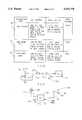
- FIG. 1is a block diagram of a security system made in accordance with the teachings of a preferred embodiment of this invention
- FIG. 2is an illustration of the data communication format used by the preferred embodiment of this invention.
- FIG. 3is a flowchart illustrating the sequence of steps associated with the selection of a transmit time interval for each of the alarm activation elements shown in FIG. 1;
- FIGS. 4a and 4bare top views of the control transmitter shown in FIG. 1 and respectively made in accordance with a first and second transmitter embodiment of this invention
- FIG. 5is a flowchart illustrating the sequence of steps associated with the "teaching" of each of the alarm elements shown in FIG. 1 to a central console controller;
- FIG. 6is a table illustrating the various types of alarm elements used by the security system of the preferred embodiment of this invention.
- FIG. 7is a table illustrating the various switch depression functions associated with the transmitter embodiment shown in FIG. 4(b);
- FIG. 8is a table illustrating the various switch depression functions associated with the transmitter embodiment shown in FIG. 4(b);
- FIG. 9is an electrical schematic diagram of a signal detector made in accordance with the teachings of a preferred embodiment of this invention.
- FIG. 10is a block diagram of a low battery detect circuit used in combination with the alarm elements shown in FIG. 1;
- FIG. 11is a flowchart illustrating the sequence of steps associated with the identification of a "tripped” or activated alarm element
- FIG. 12is a block diagram illustrating the manner in which data is read and stored within the various microprocessor assemblies utilized by the preferred embodiment of this invention.
- FIG. 13is a block diagram illustrating the use of the system shown in FIG. 1 in combination with a typical automobile security system
- FIG. 14is a block diagram illustrating the use of a mattress sensor in combination with the system shown in FIG. 1;
- FIG. 15is a block diagram illustrating a remote and central alarm monitoring system in combination with the system shown in FIG. 1;
- FIG. 16is a block diagram illustrating the use of system of the preferred embodiment of this invention in combination with a typical "hard wired" home or structural security system;
- FIG. 17is a block diagram of the various alarm elements shown in FIG. 1;
- FIG. 18is a block diagram illustrating the annunciator shown in FIG. 1;
- FIG. 19is a block diagram of the console shown in FIG. 1 and including a telephone interface portion;
- FIG. 20is a block diagram of the repeater shown in FIG. 1;
- FIG. 21is an electrical schematic diagram of the transmitters shown in FIGS. 4(a-b);
- FIG. 22is a block diagram of a telephone receiver interface unit made in accordance with the teachings of the preferred embodiment of this invention.
- FIG. 23is a block diagram of the central alarm receiver shown in FIG. 5;
- FIG. 24is an illustration of a typical record used by the central alarm receiver shown in FIG. 23;
- FIG. 25is a block diagram of a siren
- FIG. 26is a block diagram of a microphone/speaker assembly portion of the security system of this invention.
- FIG. 27is a block diagram of a telephone jack interface assembly employed by the security system of this invention.
- FIG. 28is a charge pump assembly employed by the security system of this invention.
- FIG. 1there is shown a security system 10 made in accordance with the teachings of the preferred embodiment of this invention and adapted for use in a home, residence, or other structure.
- system 10includes several alarm activation elements such as a smoke detector 12, passive infrared element 14, door/window element 16, 18, motion detection element 20, siren 22, and a heat sensor 23 which are wirelessly, electrically, and communicatively coupled to a central console controller 24.
- alarm activation elementssuch as a smoke detector 12, passive infrared element 14, door/window element 16, 18, motion detection element 20, siren 22, and a heat sensor 23 which are wirelessly, electrically, and communicatively coupled to a central console controller 24.
- such couplingmay be achieved by the use of electromagnetic radiation having a frequency in the radio, infrared, ultrasonic, ultraviolet, or any other desirable range.
- wireless communicative couplingis achieved by the selective generation of signals 26 from elements 12-23 and by the selective generation of signals 25, 82 from console 24.
- System 10also includes a repeater 28 which is adapted to receive one of the signals 26 from console 24 and each of the elements 12-23 and to produce a signal 30 or 31 having substantially the same data structure as the received signal.
- the use of repeater 28increases the allowable communication distance between console 24 and elements 12-23 and allows for desirable and controlled operation even though many physical obstructions may lie between elements 12-23 and console 24.
- system 10includes a remote keypad 32, transmitter 27, and an annunciator 34, each of which will be described.
- Each of the elements 12-23 and console 24may be coupled to a source of electrical power 36, or may each have a portable electric battery 37, each of the plurality of batteries being uniquely coupled to one of the elements 12-23 and to console 24.
- FIG. 17shows a block diagram 50 representing the structure of each of the elements 12, 14, 16, 18, 20, 22, and 23.
- each of these elements 12-23includes a microprocessor 52 under stored program control and having an output signal 54 coupled to an amplifier 56.
- the output of amplifier 56is coupled to an antenna 58 in the configuration associated with elements 12-23 or to a sound or siren generator 60 in the configuration associated with element 22.
- microprocessor 52in the embodiments associated with elements 16 and 18, is coupled to a conventional switch 62 having a stationary portion 64 mounted upon a door or window frame and a second movable portion 66 mounted upon the door or window and magnetically coupled to the stationary first portion 64.
- a conventional switch 62having a stationary portion 64 mounted upon a door or window frame and a second movable portion 66 mounted upon the door or window and magnetically coupled to the stationary first portion 64.
- an alarm notification signal 68causes an alarm notification signal 68 to be generated to microprocessor 52.
- microprocessor 52Upon receipt of signal 68, microprocessor 52 generates the signal 54 which causes an electromagnetic signal 26 to emanate from antenna 58. In this manner, console 24 is made aware of a door or window opening.
- switch 62is replaced with an infrared transceiver 70, adapted to output an infrared signal 72 and to detect signal interference.
- transceiver 70may utilize other forms of radiation including visible light.
- signal 72i.e. such as when someone enters a room having element 14
- transceiver 70sends an alarm notification signal 74 to microprocessor 52.
- microprocessor 52Upon receipt of signal 74, microprocessor 52 generates the output signal 54 which is amplified and output to antenna 58.
- Signal 26is then produced by antenna 58 and communicated to console 24. In this manner, console 24 is made aware of the presence of someone entering a room.
- motion control activation element 20comprises microprocessor 52, amplifier 56, and antenna 58 in combination with a typical motion control sensor element 76.
- Sensor 76is adapted to be mounted upon a window or other portion of a house.
- an alarm notification signal 78is coupled to microprocessor 52 and causes the microprocessor 52 to generate signal 54 in the manner previously described. In this manner, a signal 26 is generated to console 24 effective to indicate unwanted motion.
- microprocessor 52is coupled to a smoke detection sensor 80 which generates an alarm notification signal 82 to microprocessor 54 upon the detection of smoke.
- microprocessor 52Upon receipt of signal 82, microprocessor 52 generates signal 54 to antenna 58 in the previously-described manner. A signal 26 is then produced, indicating the presence of smoke.
- a conventional heat detection sensor 83is coupled to microprocessor 52 and generates an alarm notification signal upon detection of heat.
- microprocessor 52Upon receipt of the generated heat detection signal, microprocessor 52 generates a signal to console 24 by means of antenna 58 thereby informing console 24 of the detection of heat.
- elements 12, 14, 16, 18, 20, 22, and 23may be constructed by use of a single microprocessor 52 and may selectively generate an electromagnetic signal 26 to console 24 upon the occurrence of an alarm condition such as the detection of smoke, door or window opening, motion and/or heat detection, or the interruption of an infrared field.
- console 24Upon receipt of an alarm signal 26, console 24, according to the teachings of the preferred embodiment of this invention, is adapted to provide certain functionality which will be described and which is defined by a stored computer program.
- signal 25is also selectively effective to suppress the generation of signal 26 from certain of the elements 12-20 and 23.
- element 14is prevented from generating a signal 26 in order to prevent false system activation by an individual home resident moving throughout the house.
- each element 12-20 and 23may be allowed to generate signals 26 in the foregoing manner since "false alarms" will not be generated by house residents.
- each element 12-20 and 23may always be allowed to appropriately generate signals 26, but some of these signals are ignored and not acted upon by console 24 when in the "home” or "away” activation modes. This alternative configuration allows elements 12-20 and 23 to have a simpler stored program.
- siren element configuration 22(shown in FIG. 25) a microprocessor 700 is coupled through an amplifier 56 to a sound generator 60 which generates a sound of a selected volume and frequency. Such sound, in the preferred embodiment of this invention, is generated only upon receipt of a signal 82 to antenna 701 and emanating from console 24. In this manner, siren 22 may be selectively "activated” (i.e. allowed to produce sound) upon receipt by console 24 of any of the signals 26 emanating from elements 12, 14, 16, 18, 20, and/or 23.
- repeater 28is used to insure that signals 26 emanating from each of the elements 12-23 are received by console 24 and that any signals 25 emanating from console 24 are received by these elements 12-23.
- repeater 28includes a microprocessor 85 under stored program control, a memory 86 containing the stored program, an antenna 87, and transceiver 88.
- Analogue signal 25is received through antenna 87 and transceiver 88, which includes an analog to digital converter.
- the digitized datais coupled to microprocessor 85 and eventually stored into memory 86.
- the stored datais then coupled to transceiver 88, converted to analogue form, and re-transmitted as signal 30 from antenna 87.
- Such stored retransmissionis preferred over conventional signal amplification since noise and spurious signal reductions are improved.
- such retransmissionallows for error correction processing of the received data and also allows for a transmitted signal of greater power.
- repeater 25could be replaced with a conventional amplifier arrangement that is effective to receive signal 25, amplify the received signal, and transmit the amplified signal to elements 12-23.
- each repeated data streamhas a tag appended to it in order to ensure that the data is identified as repeated by a specific repeater. In multiple repeater systems, such a tag is used to prevent two or more repeaters from continually repeating the data (i.e. only a single repeat of the data is allowed by each repeater).
- annunciator 34includes a microprocessor 90 under stored program control and having an input which is in wireless communication with console 24 by means of signal 94.
- Microprocessor 90has an output coupled to a liquid crystal display 92.
- console 24generates an electromagnetic signal 94 which is received by microprocessor 90 and which causes microprocessor 90 to generate a signal 96 to liquid crystal display portion 92.
- Signals 94 and 96each identify those elements 12, 14, 16, 18, 20, 22, and 23 which are currently "activated" (i.e. capable of selectively generating a signal 26), those elements 12-23 which have generated a signal 26, and the mode that system 10 is operating within (i.e.
- annunciator 34may be easily adapted to display any desired aspect of system 10 operation in order to improve status recognition and that liquid crystal display portion 92 may be replaced with virtually any other type of display including a cathode ray tube monitor and/or a light emitting diode array.
- FIG. 2where there is shown a data format 100 made in accordance with the teachings of the preferred embodiment of this invention and used within signals 25, 26, 82, and 94.
- data format 100includes a first twelve bit portion 102 used as a preamble in order to allow the receiving entity 12-24 and 34 to synchronize its conventional internal clock (not shown) to the stream of data which is to follow, and to allow the receiving entity 12-24 and 34 to determine the data rate.
- Format 100further includes a second four bit portion 104 having a series of logically low values and adapted to increase noise immunity of data included within format 100.
- format 100further includes a third thirty-two bit portion 106 which is used to transmit alarm data.
- format 100employs manchester coding in which a logically low value is represented by a first half bit having a carrier of a frequency of approximately 314.2 Mhz followed by an absence of the carrier in the next half bit.
- a logically high valuereverses the order of carrier and non-carrier intervals.
- Each bit widthis approximately 400 micro-seconds.
- portion 100is used by elements 12-23 to identify themselves to console 24 and to indicate various alarm conditions.
- portion 106 of elements 16 and 18comprises the following format:
- each element 12-23periodically transmits a test signal 26 to console 24 at predetermined intervals of time in order to allow console 24 to ascertain whether these elements 12-23 continue to function.
- portion 106 of signal 82comprises the following format:
- portions "ZZZZZZZ”are used to provide additional element commands.
- values associated with portion "ZZZZZ”may selectively cause microprocessor 52 to selectively deactivate siren 22 or to briefly generate a sound in order to determine whether siren 22 remains operational.
- timing software routineis necessary.
- the timing routineis embedded within the software controlling microprocessor 52 and is effective to reduce the probability of substantially simultaneous transmissions from two different elements 12-23, 28, and 34. Such simultaneous transmissions may destructively and electromagnetically interfere thereby preventing desired communication with console 24.
- the identification code for each of the elements 12-23, 28, and 34form a binary sequence and are predetermined in a random manner and are stored within these elements 12-23, 28, and 34 before such system 10 becomes operational.
- predetermined identification codesare used by the preferred embodiment of this invention to reduce the probability of destructive transmission interference.
- each element 12-23, 28, and 34is adapted to transmit signal 26 only during a specific transmit interval period after receipt of an alarm notification signal (i.e. such as the signal produced by switch 62). This transmit interval portion is defined in step 116.
- the defined transmit intervalis divided into four sections in step 118, but in other embodiments of this invention may be divided in different numbers of sections.
- step 120the first two bits of the unique and randomly generated identification format or code for each of the elements is selected.
- step 122the transmit interval section is selected by use of the first two bits which were produced in step 120. For example, bits “10” (where “1” denotes a logically high value and "0” denotes a logically low value) denotes section two, bits "00" denote section zero, bits "11” denote section three, and bits "01” denote section one.
- the second, third, and fourth, and other consecutive bit pairsare then used to further define transmit intervals. In this manner, as shown in step 123 and 125 twenty transmissions are achieved.
- each element 12-23is made to continuously generate data for the entire predetermined section time, thereby allowing the data that may have been destructively interfered with during a portion of time to eventually be received by controller 24.
- remote keypad 32may be substantially identical to the transmitter shown in FIG. 21 and explained below except that keypad 32 may include a plurality of switches which allow keypad 32 to perform the below-described functions of transmitter 27 and to create codes for each element 12-23 within console 24. These codes may also be created by a remote programming terminal.
- transmitter 27includes a microprocessor 123 under stored program control, switches 124, 126, oscillator 127, and antenna 128. It should be noted that different numbers of switches 124, 126 may be employed in other embodiments of transmitter 27.
- depression of switches 124, 126causes microprocessor 123 to activate oscillator 127 such that a unique signal is output from oscillator 127 for each respective depression of switches 124, 126 and for a dual switch depression.
- the output signal from oscillator 127is coupled to antenna 128 where it is output as signal 29.
- transmitter 27includes a "home” switch 129, an "away” switch 131, a “disarm” switch 133, and a “panic” switch 135.
- depression of any of the switches 129, 131, 133, and 135causes a unique electromagnetic signal 29 to be generated and transmitted. Any concomitant depression of two or more of these switches 129, 131, 133, and 135 also causes a respectively unique signal 29 to be generated.
- depression of switch 129causes certain of the elements 12-23 to be enabled in a first "home” mode, while depression of switch 131 causes signal 29 to be effective, when received by controller 24 to cause certain of the elements 12-23 to be enabled in the second "away” mode.
- a "non-enabled” elementwill not selectively generate electromagnetic signals 26 even though its alarm condition may have been achieved (i.e. its microprocessor 52 receives an alarm notification signal).
- Depression of switch 133disables each of the elements 12-23 while depression of switch 135 generates a signal 26 to console 24 which places the console in its "alarm” mode.
- a disabling of elements 12-23may also be accomplished by having console 24 ignore or fail to respond to certain of the signals 26 emanating from the disabled elements 12-26.
- console 24first learns the transmitter identification code in step 132. Specifically, in the preferred embodiment of this invention, each transmitter 27 is made to have one of a plurality of predetermined binary identification codes. Console 24 is put into a "learn" mode and transmitter 27 is made to generate signal 29, including the unique identification bits associated with the transmitter. Upon receipt of the identification bits, console 24 places these bits in memory. Upon a later transmission by the transmitter 27, console 24 compares the currently generated identification bits to those stored. If this comparison is identical, console 24 responds in the requested manner. Should this comparison fail, console 24 fails to respond or ignores the received command.
- each of the elements 12, 14, 16, 18, 20, 22, and 23have a unique identification code which is learned in this manner by the console 24.
- each of the learned elementsis assigned a unique zone number, while in step 136 each of the elements is assigned one of several predefined element functions.
- console 24may recognize the identification codes as it receives them thereby obviating the need for a formal programming procedure.
- FIG. 6where there is shown a table 150.
- ten distinct types of predefined alarm elementsare employed, and are selectively attached to or uniquely associated with one or more of the elements 12-23. That is, each element 12-23 employed within system 10 is made to have one element of this configuration uniquely associated with it. The associated configuration is stored within the memory of console 24 and used to determine the response of console 24 to a signal 26 emanating from these elements 12-23. In this manner, a user of system 10 simply needs to define or ascertain the type of elements that are to be used and does not need to explore exactly how the defined element operates. Such predefined operational element signatures therefore allows system 10 to be easily installed, configured, and later modified.
- a first element type 152is referred to as a "DW instant" and is uniquely associated with elements 16 and 18.
- console 24responds to a signal 26 emanating from elements 16 and 18 in both the “home” and “away” modes. Moreover, console 24 activates siren 22 upon receipt of signal 26 generated from elements 16 and 18.
- Second element type 154is referred to as a "DW delay” and differs from type 152 in that the console response to signals 26 is delayed a certain amount of time. If console 24 receives a disarm signal before the end of a certain entry delay interval, console 24 will ignore the signal. This allows, for example, a homeowner to enter the house and deactivate system 10 before siren 22 is activated. Such deactivation being allowed even though these elements 16, 18 have been “tripped” or received an alarm activation signal.
- the third element type 156is referred to as a "PIR" and is a passive infrared type which is uniquely associated with element 14. As shown, console 24 responds to a signal 26 emanating from device 14 only when console 24 is in the "away mode". Such response includes siren activation. Fourth element type 158 is referred to as a "panic” type and is uniquely associated with signals emanating from transmitter 27. Depression of switch 135, by a first embodiment of transmitter 27, will cause the activation of siren 22 regardless of the mode that the system is In. Fifth transmitter type 160 is substantially similar to type 158 with the exception that a conventional "medical" transmitter 137 may replace transmitter 27.
- Sixth element type 162is referred to as a "smoke" type and is uniquely associated with smoke detector element 12.
- Console 24 upon receipt of signal 26 emanating from transmitter type 162operates in a manner which is substantially identical to console operation associated with types 156, 158, and 160.
- Seventh element type 164is referred to as a "heat” type and is uniquely associated with heat element 23.
- Console operation associated with a receipt of signal 26 emanating from element 23is substantially identical to console operation associated with types 156-162.
- Eighth element type 166is referred to as a "glass break” and is uniquely associated with motion detector 20. As shown, motion detector 20 become activated in the "home” and “away” alarm system modes and is further effective to have console 24 generate a signal to siren 22 effective to activate the siren upon receipt of signal 26 from detector 20.
- the ninth element typeis referred to as "utility" type and is associated with a conventional sensor 181 used to detect such occurrences as a high water level.
- Console 24responds to sensor 18 regardless of the current alarm system mode but does not activate siren 22.
- Sensor 181, in the preferred embodiment of this inventionmay be substantially similar to heat detection sensor 33 with the exception that sensor 83 is replaced with a level sensor (not shown).
- the last alarm element type of the preferred embodiment of this inventionis referred to as an "interior” type 170.
- Console 24responds to a signal 26 emanating from element type 170 only during an "away" mode. Such console response includes siren activation. In this manner, interior sensor 170 will not become activated by an activity occurring within the house but will only become activated upon entry from outside of the house.
- element 18deployed upon a basement door. Defining element 18 in this interior manner allows individuals residing within the house to use the basement door without activating the alarm but when gone, to arm the door against entry. Moreover, as further shown in FIG. 6, element types 152 and 154 are also effective to cause console 24 to activate siren 22 when receiving a previously-described "check-in" signal 26 while only element types 156-162 may be deleted by means of console 24.
- transmitter 27'may be of one of six types shown in FIGS. 7 and 8.
- transmitter 27' in the first embodimentis effective to place system 10 in the "home mode” on a first depression of switch 172 and in the "away mode” on a subsequent depression.
- depression of switch 172is effective to place system 10 in either an armed “home” or armed “away” mode while depression of switch 174 places system 10 in the "disarm” mode.
- depression of both switches 172, 174causes a "panic” system response. In this manner, it should be apparent to one of ordinary skill in the art, that two switch transmitter 27' may be easily and selectively adapted to meet a wide variety of needs.
- two switch transmitter 27'may alternatively be of a type 188, 190, or 192.
- transmitter type 188switch 172 concurrently (with each depression) arms system 10 in an armed/home, armed/away, and disarmed mode.
- Switch 174is not employed for use in security system 10 but may alternatively be used to arm and disarm a typical vehicle alarm. As before, depression of both switches 172, 174 causes a panic operation to occur.
- transmitter type 190depression of switch 172 arms system 10 in a "home” mode only while a second depression of switch 172 disarms system 10.
- depression of both switches 172, 174causes a panic situation.
- Switch 174is used to activate a typical vehicle alarm.
- Transmitter type 192is effective when switch 172 is depressed to selectively arm system 10 in the "away mode”. A second depression of switch 172 disarms system 10. Selective depression of both switches 172, 174 causes a panic situation to occur while a selective depression of the right switch may be used in conjunction with a typical vehicle alarm system.
- two switch transmitter 27'may be selectively modified to allow the transmitter to be used in combination with a typical vehicle alarm system (not shown) and with a home security system, such as that shown and described with reference to FIG. 1.
- remote keypad 32includes no code stored therein in order to substantially prevent a thief from learning the code. Rather, central station 24 learns the code emanating from keypad 32 in a manner previously described.
- each of the elements 12-23, controller 24, and repeater 28 which are selectively adapted to receive a signal 26, 25, 30are normally placed in a "passive" mode and are "awaken” or made operational only upon recognition of a modulation signal envelope, corresponding to a signal to be received.
- the means for recognitionis a passive low or non-power consumption device such as a crystal detector.
- signals 25, 26, 29, 94, and 31are amplitude modulated through other types of modulation techniques may be employed.
- antenna 58 of each element 12-23is coupled to electrical ground through a parallel arrangement of inductance coil 214 and capacitor 216.
- Antenna 58is further coupled, as are coil 214 and 216, to a series arrangement of diode 218, capacitor 220, and a low power amplifier 222.
- the output of amplifier 222is coupled to the conventional "IRQ" port of microprocessor 52.
- microprocessor 52is placed in an activated state only when coil 214 and capacitor 216 detect the occurrence of an amplitude modulated signal, thereby conserving power during periods of non-system communication.
- the inductance of coil 214is selected in order to allow for different types of carrier frequencies to be utilized within system 10.
- microprocessor assembly 52 of each of the elements 12-23is modified according to the electrical schematic diagram 240 of FIG. 10. Specifically, microprocessor 52 which has an output antenna 58 which is adapted to cooperate with microprocessor 52 in order to generate output signals 26 in the previously-described manner. Moreover, in the preferred embodiment of this invention, microprocessor 52 has a first input which is coupled to a first resistor 242 and a second input coupled to resistor 244 and in parallel with resistor 242. Resistor 244 is coupled to a source 245 of approximately nine volts.
- microprocessor 52is adapted to generate a signal 26 by means of antenna 58.
- the selectable amountis defined to be the device threshold.
- resistor 242is selectively coupled to ground when battery detection is required and is made to float otherwise. In this manner, power consumption by microprocessor 52 is reduced wherein a "sleep" state sure process 52 comprises a microchip PIC 16C54.
- memory 51is coupled to a conventional grey scale conversion device 264 which receives the output or "read” data (having certain memory pointers which are used to identify the location the data is to be restored within) from memory 51, converts the "read” data to grey scale values, and stores the modified data in various locations within memory 262. These various locations differ from the locations which originally contained the data. In this manner, the "read-cycles" associated with the various locations within memory 262 are reduced.
- a conventional grey scale conversion device 264which receives the output or "read” data (having certain memory pointers which are used to identify the location the data is to be restored within) from memory 51, converts the "read” data to grey scale values, and stores the modified data in various locations within memory 262. These various locations differ from the locations which originally contained the data. In this manner, the "read-cycles" associated with the various locations within memory 262 are reduced.
- console Z4is further adapted to identify these elements 12-23 have been activated.
- console 24is adapted in step 302 to store the unique identification data associated with those elements 12-20 and 23 which have generated a signal 26.
- console 24is further adapted to activate each of the elements 12-20 and 23.
- console 24compares each of the activated identification data received in step 302 with the stored identification data. This comparison, in step 308, is effective to identify the activated element.
- identificationsas previously described, may be transmitted to annunciator 34 by means of signal 94.
- vehicle security system 350includes an antenna 351 and a transmitter 353.
- System 350is electrically coupled to vehicle starter 354 and produces a signal 356, by means of transmitter 353, when starter 354 is activated (i.e. when the engine (not shown) is started).
- Signal 356is effective to cause console 24 to activate system 10 in either the "away" or "home” mode.
- system 10becomes activated when a homeowner leaves the house.
- the auto security systemmay be further adapted upon the deactivation of the auto ignition to provide a signal to console 24 indicating that the automobile is in the garage.
- the automobiletherefore becomes a security element of system 10, much like elements 16, 18 which provide a signal when a contact has been broken (i.e. the ignition is activated).
- console 24may be further adapted to receive a signal 400 from a pressure sensor assembly 402 (similar to element 20) placed within or under mattress 404.
- a pressure sensor assembly 402similar to element 20
- an individual residing within house 358when retiring for the evening, automatically activates sensor 402 thereby causing signal 400 to be produced.
- console 24Upon receipt of signal 400, console 24 automatically activates system 10 in the "away” mode and upon release of sensor 402 (i.e. when resident 360 lowers mattress 404), signal 400 causes console 24 to activate system 10 in the "home” mode, allowing the individual to travel through the house. In this manner, formal activation and deactivation of system 10 is obviated when individuals residing within home 358 go to bed.
- system 10may have a remote annunciator (i.e. voice) which automatically inform a user in automobile 357 or within room 359 of the state of the system and either automatically changes the state or awaits further commands to do so.
- a remote annunciatori.e. voice
- the status of system 10may also be used for other purposes. For example, an "armed away mode" indicates that residents are gone from a house and this information may be used to automatically turn down the heat and turn off or deactivate certain appliances, such as a coffeemaker.
- console 24may be further adapted to signal a central and remote alarm station 420 upon alarm activation.
- receiver 422wirelessly receives signal 421 emanating from console 24 and produces modulated data upon a conventional telephone line 424.
- remote station 420demodulates the data by means of modem 425 and becomes aware of an activation within home 358.
- telephone interface receiver 22comprises a microprocessor 450 having a memory 452 which contains a stored program that controls the operation of microprocessor 450.
- Receiver 422further includes an antenna 454 which is adapted to wirelessly receive signal 421 from console 24 and to couple the received signal to microprocessor 450.
- receiver interface 422includes a conventional telephone jack 456, such as a RJ-11 or RJ-455.
- analogue signal 421is received by antenna 454 and coupled to microprocessor 450.
- the analog signal 421is digitized and modulated by microprocessor 450 and the modulated and digital signal is placed onto telephone line 424 by means of interface 456.
- receiver 422wirelessly receives alarm data from controller 24 and transmits this wireless data to a central alarm station 420 by means of a conventional telephone line 424.
- coupler 456may comprise a conventional auto-dial modem which is coupled to a telephone 460 and which dials a telephone number of central station 420, having a second auto-dial modem 425. In this manner a "hard-wired" telephone line is not required between station 420 and dwelling 358, thereby reducing cost.
- console 24having a microprocessor 224 and a memory 262 which contains a stored program to control microprocessor 224 in the previously-described manner, is physically connected to a telephone interface 506.
- console 24includes an antenna 508 which cooperates with microprocessor 224 to produce signals 25 and 94 and to receive signals 26 and 29 in the previously-described manner.
- Microprocessor 224further includes an analog to digital converter 510 which digitizes the received analog signals 26 and 29 and produces analog signals 25 and 94 from digital data residing in microprocessor 224.
- microprocessor 224receives an analog alarm signal 26 from elements 12-23, digitizes the signal, and couples the digital signal to square-wave circuits 502 and filter 504, effective to correctly shape and modify the signal for remote transmission.
- the digitized and shaped signalsis coupled to a typical telephone interface 506 where it is modulated upon a conventional telephone line 424 in the manner previously described.
- this second telephone interface embodimentdiffers from that shown and described with reference to FIG. 22 in that a wire must be physically coupled between interface 506 and microprocessor 224.
- system 10may also include several conventional microphones and speaker assemblies 800, 802 which are coupled to console 24 and which may be distributed throughout the secured structure or house.
- Console 24i.e. microprocessor 2264 upon receipt of a signal or telephone line 810 allows audio signals from assemblies 800, 802 to be placed on the line 810 and further allows signals from line 810 to be coupled to assemblies 800, 802. In this manner, one may "dial up" system 10 and monitor audible signals in a house or structure and further communicate with those in the home.
- console 24may also include a correctional audio recorder 820 which is adapted to recordably store audio signals emanating from assemblies 800, 802 at a predetermined time after alarm activation and/or before alarm activation. Such prealarm activation recorded is achieved since, in this embodiment, audio signals are received and recorded continually. Hence, audio signals are recorded even during unwanted entry but before such entry activates or alarms the system (i.e. during an alarm delay interval).
- an alarm system 600comprising a typical hard-wired security system 602 including a central controller 604 which is physically coupled to several alarm activation elements 606, 608.
- console controller 24'made in accordance with the teachings of a preferred embodiment of this invention and wirelessly communicating to alarm activation 12', 14', 18' which are respectively and substantially similar to elements 12, 14, and 18, may be coupled to controller 604.
- an existing security system 602may be readily expanded to have the functionality associated with various of the elements 12-23 shown and previously-described with reference to system 10.
- each system 602 and 600operates in a separate and unique manner until controller 24' receives a signal 26' from any of the elements 12', 14', and 18'.
- controller 24'Upon receipt of signal 26', controller 24' generates a signal 610 to controller 604 indicating that one of the elements 12', 14', or 18' has detected an alarm occurrence.
- This signal 610thereby causes controller 604 to generate an alarm in a manner consistent with its normal operation. Therefore, it should be apparent to one of ordinary skill in the art that the wireless home security system of the preferred embodiment of this invention may be readily adapted for use in combination with a typical "hard wired home security system", in order to provide additional needed functionality.
- system 24'also is adapted to provide a true indication of the opening state of doors and windows.
- station 420may comprise one or more personal computers 700 coupled to one or more conventional modems 702. These modems are in communication with microprocessor 224 of controller 24.
- personal computer 700Upon receipt of alarm information from system 10, personal computer 700, which is under stored program control, is adapted to present such alarm information upon its screen 704 in order to inform an operator of the alarm. This obviates the need for a relatively expensive dedicated receiver. Alternatively, the data may be sent to another display computer.
- each dwelling 358in the preferred embodiment of this invention, has a unique configuration file or table 706 associated with it.
- each of these files 706are resident within computer 700 and are also displayed upon a receipt of an alarm signal from the dwelling.
- the fileincludes the home address, the type of controller used within the dwelling, billing information, and other special instructions such as those individuals who are to be called in the event of an alarm.
- These filesmay be downloaded to computer 700 from a remote site or may be periodically updated by a user of the computer 700.
- modem 702may, in the preferred embodiment of this invention, be a conventional low-speed modem since computer 700 is adapted to provide artificial breaks within the modulated data thereby "artificially" modulating the data in a manner which will allow system 420 to be used with a higher speed modem employed by controller 24.
- system 10may also include a plurality of relays 902 which are adapted to be coupled to the conventional yellow and black wires of a typical telephone line.
- Each relay 902is coupled to a unique telephone jack 903 and is adapted to selectively disconnect jack 903 from the conventional tip and ring telephone line portions upon a signal from console 24.
- Such signal, from console 24may be placed on the yellow and black wires or transmitted to relay 902 through any desired medium. In this manner, telephone interruptions of a security message, placed on the telephone line 900, is minimized.
- each transmitting element 950 of system 10includes a regulator 952 coupled to a source of electrical power 36, 37 and providing a regulated power input to microprocessor 954.
- each transmitting element 950(as shown best in FIG. 28) further includes a conventional charge pump 956 coupled to the power port of microprocessor 954 and to antenna and radio frequency transmitting portion 958. In this manner, a lower voltage is needed from battery 36, 37 to operate thereby increasing the operational voltage window and allowing element 950 to operate for a longer period of time with battery 36, 37.
Landscapes
- Engineering & Computer Science (AREA)
- Computer Networks & Wireless Communication (AREA)
- Business, Economics & Management (AREA)
- Emergency Management (AREA)
- Physics & Mathematics (AREA)
- General Physics & Mathematics (AREA)
- Mechanical Engineering (AREA)
- Alarm Systems (AREA)
Abstract
Description
1 xxx xxxx xxxx FFFF 1 xxx xxxx xxxx TSSP
1 ZZZ xxxx xxxx FFFF 0ZZZ xxxx xxxx TSSP
TABLE 1 ______________________________________ RESISTOR VALUES FOR DIGITAL TO ANALOGUE CONVERTER R1 R2 R3 R4 Top Res Bot Res D-A Result ______________________________________ 1 0 0 0 0 ∞ 506 0.0% 2 0 0 0 1 ∞ 541 0.0% 4 0 0 1 0 ∞ 580 0.0% 10 0 1 0 0 ∞ 678 0.0% 5 0 0 1 1 ∞ 625 0.0% 11 0 1 0 1 ∞ 741 0.0% 13 0 1 1 0 ∞ 816 0.0% 28 1 0 0 0 ∞ 1,026 0.0% 14 0 1 1 1 ∞ 909 0.0% 29 1 0 0 1 ∞ 1,176 0.0% 31 1 0 1 0 ∞ 1,379 0.0% 37 1 1 0 0 ∞ 2,105 0.0% 32 1 0 1 1 ∞ 1,667 0.0% 38 1 1 0 1 ∞ 2,857 0.0% 40 1 1 1 0 ∞ 4,444 0.0% 41 1 1 1 1 ∞ 10,000 0.0% 3 0 0 0 2 8,000 541 6.3% 6 0 0 1 2 8,000 625 7.2% 12 0 1 0 2 8,000 741 8.5% 15 0 1 1 2 8,000 909 10.2% 7 0 0 2 0 4,000 580 12.7% 30 1 0 0 2 8,000 1,176 12.8% 8 0 0 2 1 4,000 625 13.5% 16 0 1 2 0 4,000 816 16.9% 33 1 0 1 2 8,000 1,667 17.2% 17 0 1 2 1 4,000 909 18.5% 9 0 0 2 2 2,667 625 19.0% 19 0 2 0 0 2,000 678 25.3% 18 0 1 2 2 2,667 909 25.4% 34 1 0 2 0 4,000 1,379 25.6% 39 1 1 0 2 8,000 2,857 26.3% 20 0 2 0 1 2,000 741 27.0% 22 0 2 1 0 2,000 816 29.0% 35 1 0 2 1 4,000 1,667 29.4% 23 0 2 1 1 2,000 909 31.3% 21 0 2 0 2 1,600 741 31.6% 24 0 2 1 2 1,600 909 36.2% 25 0 2 2 0 1,333 816 38.0% 36 1 0 2 2 2,667 1,667 38.5% 26 0 2 2 1 1,333 909 40.5% 27 0 2 2 2 1,143 909 44.3% 55 0 0 0 0 1,000 1,026 50.6% 46 1 2 0 0 2,000 2,105 51.3% 43 1 1 2 0 4,000 4,444 52.6% 56 2 0 0 1 1,000 1,176 54.1% 42 1 1 1 2 8,000 10,000 55.6% 57 2 0 0 2 889 1,176 57.0% 58 2 0 1 0 1,000 1,379 58.0% 47 1 2 0 1 2,000 2,857 58.8% 59 2 0 1 1 1,000 1,667 62.5% 61 2 0 2 0 800 1,379 63.3% 48 1 2 0 2 1,600 2,857 64.1% 60 2 0 1 2 889 1,667 65.2% 62 2 0 2 1 800 1,667 67.6% 64 2 1 0 0 1,000 2,105 67.8% 49 1 2 1 0 2,000 4,444 69.0% 63 2 0 2 2 727 1,667 69.6% 44 1 1 2 1 4,000 10,000 71.4% 65 2 1 0 1 1,000 2,857 74.1% 73 2 2 0 0 667 2,105 75.9% 66 2 1 0 2 889 2,857 76.3% 52 1 2 2 0 1,333 4,444 76.9% 45 1 1 2 2 2,667 10,000 78.9% 74 2 2 0 1 667 2,857 81.1% 67 2 1 1 0 1,000 4,444 81.6% 75 2 2 0 2 615 2,857 82.3% 50 1 2 1 1 2,000 10,000 83.3% 70 2 1 2 0 800 4,444 84.7% 51 1 2 1 2 1,600 10,000 86.2% 76 2 2 1 0 667 4,444 87.0% 53 1 2 2 1 1,333 10,000 88.2% 79 2 2 2 0 571 4,444 88.6% 54 1 2 2 2 1,143 10,000 89.7% 68 2 1 1 1 1,000 10,000 90.9% 69 2 1 1 2 889 10,000 91.8% 71 2 1 2 1 800 10,000 92.6% 72 2 1 2 2 727 10,000 93.2% 77 2 2 1 1 667 10,000 93.8% 78 2 2 1 2 615 10,000 94.2% 80 2 2 2 1 571 10,000 94.6% 81 2 2 2 2 533 10,000 94.9% ______________________________________
Claims (1)
Priority Applications (1)
| Application Number | Priority Date | Filing Date | Title |
|---|---|---|---|
| US08/049,464US5543778A (en) | 1993-04-19 | 1993-04-19 | Security system |
Applications Claiming Priority (1)
| Application Number | Priority Date | Filing Date | Title |
|---|---|---|---|
| US08/049,464US5543778A (en) | 1993-04-19 | 1993-04-19 | Security system |
Related Child Applications (1)
| Application Number | Title | Priority Date | Filing Date |
|---|---|---|---|
| US29041123Continuation-In-Part | 1995-07-07 |
Publications (1)
| Publication Number | Publication Date |
|---|---|
| US5543778Atrue US5543778A (en) | 1996-08-06 |
Family
ID=21959956
Family Applications (1)
| Application Number | Title | Priority Date | Filing Date |
|---|---|---|---|
| US08/049,464Expired - LifetimeUS5543778A (en) | 1993-04-19 | 1993-04-19 | Security system |
Country Status (1)
| Country | Link |
|---|---|
| US (1) | US5543778A (en) |
Cited By (171)
| Publication number | Priority date | Publication date | Assignee | Title |
|---|---|---|---|---|
| US5714933A (en)* | 1995-01-10 | 1998-02-03 | Sgs-Thomson Microelectronics S.A. | System for protection of goods against theft |
| US5949332A (en)* | 1998-04-21 | 1999-09-07 | Jae-hoon Kim | Fire alarm radio transmitter and receiver set |
| US5973592A (en)* | 1996-01-04 | 1999-10-26 | Flick; Kenneth E. | Vehicle security system including a remote unit that emulates security system condition local indications and related method |
| EP0919972A3 (en)* | 1997-11-26 | 1999-12-01 | Meta System S.p.A. | Wireless alarm system with radiofrequency transmission of coded signals |
| US6078252A (en)* | 1997-03-28 | 2000-06-20 | Lear Automotive Dearborn, Inc. | Vehicle wireless switching system |
| WO2000060546A1 (en)* | 1999-04-01 | 2000-10-12 | Siemens Aktiengesellschaft | Device and method especially for the mobile data collection |
| US6184779B1 (en)* | 1997-01-29 | 2001-02-06 | Directed Electronics Inc. | Vehicle security system having wireless function-programming capability |
| US6243010B1 (en)* | 1998-01-08 | 2001-06-05 | Pittway Corp. | Adaptive console for augmenting wireless capability in security systems |
| US6456695B2 (en) | 1998-09-04 | 2002-09-24 | Samsung Electronics, Co., Ltd. | Computer having emergency calling function and emergency calling method using computer |
| US6462648B1 (en)* | 1999-03-13 | 2002-10-08 | Code Systems, Inc. | Vehicle security system |
| US20020147982A1 (en)* | 1999-07-20 | 2002-10-10 | @Security Broadband Corp | Video security system |
| WO2002095660A3 (en)* | 2001-05-18 | 2003-02-06 | Pittway Corp | Security system utilizing group supervision polling |
| US6518915B2 (en) | 2000-11-15 | 2003-02-11 | Geophysical Survey Systems, Inc. | Impulse radar security system |
| US20030062997A1 (en)* | 1999-07-20 | 2003-04-03 | Naidoo Surendra N. | Distributed monitoring for a video security system |
| US6555378B1 (en)* | 1998-11-09 | 2003-04-29 | Armin Schwab | Method for checking the state of the gas fill in the insulating cavity of an insulating glass pane, and insulating glass pane |
| US20030090362A1 (en)* | 2000-04-25 | 2003-05-15 | Hardwick Michael Dennis | Remote controller with energy saving |
| US20040024851A1 (en)* | 2002-02-01 | 2004-02-05 | Naidoo Surendra N. | Lifestyle multimedia security system |
| US6690411B2 (en) | 1999-07-20 | 2004-02-10 | @Security Broadband Corp. | Security system |
| US20040028190A1 (en)* | 2002-08-05 | 2004-02-12 | Golden Brian C. | Condition awareness system |
| US6707374B1 (en)* | 1999-07-21 | 2004-03-16 | Otis Elevator Company | Elevator access security |
| US20040135685A1 (en)* | 2002-09-23 | 2004-07-15 | John Hane | Security system and method |
| US20040150521A1 (en)* | 2003-02-03 | 2004-08-05 | Stilp Louis A. | RFID based security system |
| US20040160322A1 (en)* | 2003-02-03 | 2004-08-19 | Stilp Louis A. | RFID reader for a security system |
| US20040160309A1 (en)* | 2003-02-03 | 2004-08-19 | Stilp Louis A. | Communications control in a security system |
| US20040160324A1 (en)* | 2003-02-03 | 2004-08-19 | Stilp Louis A. | Controller for a security system |
| US20040160306A1 (en)* | 2003-02-03 | 2004-08-19 | Stilp Louis A. | Device enrollment in a security system |
| US20040160323A1 (en)* | 2003-02-03 | 2004-08-19 | Stilp Louis A. | RFID transponder for a security system |
| EP1159716A4 (en)* | 1998-10-23 | 2004-10-13 | Royal Thoughts L L C | Bi-directional wireless detection system |
| US20040212500A1 (en)* | 2003-02-03 | 2004-10-28 | Stilp Louis A. | RFID based security network |
| US20040212494A1 (en)* | 2003-02-03 | 2004-10-28 | Stilp Louis A. | Cordless telephone system |
| US20040212497A1 (en)* | 2003-02-03 | 2004-10-28 | Stilp Louis A. | Multi-controller security network |
| US20040212493A1 (en)* | 2003-02-03 | 2004-10-28 | Stilp Louis A. | RFID reader for a security network |
| US20050007999A1 (en)* | 2003-06-25 | 2005-01-13 | Gary Becker | Universal emergency number ELIN based on network address ranges |
| US20050151627A1 (en)* | 2003-12-31 | 2005-07-14 | Shu-Chen Lu | Wireless anti-theft device |
| EP1571054A1 (en)* | 2004-03-02 | 2005-09-07 | Tse-Hsing Chen | Wireless siren anti-theft device |
| US6960998B2 (en) | 1998-10-23 | 2005-11-01 | Royal Thoughts, Llc | Bi-directional wireless detection system |
| US20060017560A1 (en)* | 2004-07-23 | 2006-01-26 | Albert David E | Enhanced fire, safety, security and health monitoring and alarm response method, system and device |
| US20060017579A1 (en)* | 2004-07-23 | 2006-01-26 | Innovalarm Corporation | Acoustic alert communication system with enhanced signal to noise capabilities |
| US20060017558A1 (en)* | 2004-07-23 | 2006-01-26 | Albert David E | Enhanced fire, safety, security, and health monitoring and alarm response method, system and device |
| US20060120517A1 (en)* | 2004-03-05 | 2006-06-08 | Avaya Technology Corp. | Advanced port-based E911 strategy for IP telephony |
| US20060145842A1 (en)* | 2003-02-03 | 2006-07-06 | Stilp Louis A | Multi-level meshed security network |
| US20060158310A1 (en)* | 2005-01-20 | 2006-07-20 | Avaya Technology Corp. | Mobile devices including RFID tag readers |
| US20060197666A1 (en)* | 2005-02-18 | 2006-09-07 | Honeywell International, Inc. | Glassbreak noise detector and video positioning locator |
| US20060219473A1 (en)* | 2005-03-31 | 2006-10-05 | Avaya Technology Corp. | IP phone intruder security monitoring system |
| US7129833B2 (en) | 2004-07-23 | 2006-10-31 | Innovalarm Corporation | Enhanced fire, safety, security and health monitoring and alarm response method, system and device |
| US20060250260A1 (en)* | 2004-07-23 | 2006-11-09 | Innovalarm Corporation | Alert system with enhanced waking capabilities |
| US7148797B2 (en) | 2004-07-23 | 2006-12-12 | Innovalarm Corporation | Enhanced fire, safety, security and health monitoring and alarm response method, system and device |
| US20070182543A1 (en)* | 2006-02-04 | 2007-08-09 | Hongyue Luo | Intelligent Home Security System |
| EP1862980A2 (en) | 2006-06-01 | 2007-12-05 | Robert Bosch GmbH | System and method for automobile protection through residential security system |
| US20070290872A1 (en)* | 2006-06-14 | 2007-12-20 | Rinnai Corporation | Relay apparatus |
| US20080112377A1 (en)* | 2000-12-22 | 2008-05-15 | Terahop Networks, Inc. | Radio frequency identification based networks |
| US7495544B2 (en) | 2003-02-03 | 2009-02-24 | Ingrid, Inc. | Component diversity in a RFID security network |
| US7511614B2 (en) | 2003-02-03 | 2009-03-31 | Ingrid, Inc. | Portable telephone in a security network |
| US7532114B2 (en) | 2003-02-03 | 2009-05-12 | Ingrid, Inc. | Fixed part-portable part communications network for a security network |
| US20090173006A1 (en)* | 2007-12-28 | 2009-07-09 | Norifumi Jitsuishi | Vehicle door opening and closing system |
| US20090181625A1 (en)* | 2000-12-22 | 2009-07-16 | Terahop Networks, Inc. | Lprf device wake up using wireless tag |
| US20090290512A1 (en)* | 2000-12-22 | 2009-11-26 | Terahope Networks, Inc. | Wireless data communications network system for tracking containers |
| US20090322535A1 (en)* | 2008-06-30 | 2009-12-31 | Ji Shin | Car security system |
| US20100013636A1 (en)* | 2008-07-17 | 2010-01-21 | Honeywell International Inc. | Microwave ranging sensor |
| US20100067420A1 (en)* | 2000-12-22 | 2010-03-18 | Terahop Networks, Inc. | Lprf device wake up using wireless tag |
| US20100174439A1 (en)* | 2009-01-06 | 2010-07-08 | Robert Bosch Gmbh | Variable function communication gateway for vehicles |
| US20100214061A1 (en)* | 2005-06-08 | 2010-08-26 | Twitchell Jr Robert W | All weather housing assembly for electronic components |
| US20100214059A1 (en)* | 2005-06-17 | 2010-08-26 | Twitchell Jr Robert W | Event-driven mobile hazmat monitoring |
| US20100214077A1 (en)* | 2005-07-29 | 2010-08-26 | Terry Daniel J | Reusable locking body, of bolt-type seal lock, having open-ended passageway and u-shaped bolt |
| US20100265042A1 (en)* | 2009-02-05 | 2010-10-21 | Koop Lamonte Peter | Conjoined class-based networking |
| US20100279664A1 (en)* | 2009-04-30 | 2010-11-04 | Embarq Holdings Company, Llc | Self-monitored home security system using mobile communications |
| US20100330930A1 (en)* | 2000-12-22 | 2010-12-30 | Twitchell Robert W | Lprf device wake up using wireless tag |
| US20110002361A1 (en)* | 2002-12-23 | 2011-01-06 | Renishaw Plc | Signal transmission system for a measurement device |
| US20120092154A1 (en)* | 1998-06-22 | 2012-04-19 | Sipco, Llc | Systems and methods for monitoring conditions |
| US20120169487A1 (en)* | 2010-12-30 | 2012-07-05 | Comcast Cable Communications, Llc | Security system |
| US20120235803A1 (en)* | 2011-03-20 | 2012-09-20 | Todd Bunting | Security system having a vehicle glass breakage alarm |
| CN103318135A (en)* | 2013-07-08 | 2013-09-25 | 无锡商业职业技术学院 | Automobile steal-proof and grab-proof alarm |
| US20150145640A1 (en)* | 2013-11-26 | 2015-05-28 | Everspring Industry Co., Ltd. | Wireless monitoring method and device thereof |
| US9075136B1 (en) | 1998-03-04 | 2015-07-07 | Gtj Ventures, Llc | Vehicle operator and/or occupant information apparatus and method |
| US9300921B2 (en) | 1999-07-20 | 2016-03-29 | Comcast Cable Communications, Llc | Video security systems and methods |
| CN105539358A (en)* | 2016-01-08 | 2016-05-04 | 南京工程学院 | Antitheft alarm device based on GPRS |
| USD761145S1 (en) | 2011-03-20 | 2016-07-12 | Todd Bunting | Security system having a vehicle glass breakage alarm |
| US20160274759A1 (en) | 2008-08-25 | 2016-09-22 | Paul J. Dawes | Security system with networked touchscreen and gateway |
| US20170092112A1 (en)* | 2015-09-25 | 2017-03-30 | Robert Bosch Gmbh | Methods and systems for operating a point device included in a system of point devices |
| US10051078B2 (en) | 2007-06-12 | 2018-08-14 | Icontrol Networks, Inc. | WiFi-to-serial encapsulation in systems |
| US10062245B2 (en) | 2005-03-16 | 2018-08-28 | Icontrol Networks, Inc. | Cross-client sensor user interface in an integrated security network |
| US10062273B2 (en) | 2010-09-28 | 2018-08-28 | Icontrol Networks, Inc. | Integrated security system with parallel processing architecture |
| US10079839B1 (en) | 2007-06-12 | 2018-09-18 | Icontrol Networks, Inc. | Activation of gateway device |
| US10078958B2 (en) | 2010-12-17 | 2018-09-18 | Icontrol Networks, Inc. | Method and system for logging security event data |
| US10091014B2 (en) | 2005-03-16 | 2018-10-02 | Icontrol Networks, Inc. | Integrated security network with security alarm signaling system |
| US10127801B2 (en) | 2005-03-16 | 2018-11-13 | Icontrol Networks, Inc. | Integrated security system with parallel processing architecture |
| US10142166B2 (en) | 2004-03-16 | 2018-11-27 | Icontrol Networks, Inc. | Takeover of security network |
| US10142392B2 (en) | 2007-01-24 | 2018-11-27 | Icontrol Networks, Inc. | Methods and systems for improved system performance |
| US10142394B2 (en) | 2007-06-12 | 2018-11-27 | Icontrol Networks, Inc. | Generating risk profile using data of home monitoring and security system |
| US10140840B2 (en) | 2007-04-23 | 2018-11-27 | Icontrol Networks, Inc. | Method and system for providing alternate network access |
| US10156959B2 (en) | 2005-03-16 | 2018-12-18 | Icontrol Networks, Inc. | Cross-client sensor user interface in an integrated security network |
| US10156831B2 (en) | 2004-03-16 | 2018-12-18 | Icontrol Networks, Inc. | Automation system with mobile interface |
| US10200504B2 (en) | 2007-06-12 | 2019-02-05 | Icontrol Networks, Inc. | Communication protocols over internet protocol (IP) networks |
| US10237806B2 (en) | 2009-04-30 | 2019-03-19 | Icontrol Networks, Inc. | Activation of a home automation controller |
| US10237237B2 (en) | 2007-06-12 | 2019-03-19 | Icontrol Networks, Inc. | Communication protocols in integrated systems |
| US10313303B2 (en) | 2007-06-12 | 2019-06-04 | Icontrol Networks, Inc. | Forming a security network including integrated security system components and network devices |
| US10339791B2 (en) | 2007-06-12 | 2019-07-02 | Icontrol Networks, Inc. | Security network integrated with premise security system |
| US10348575B2 (en) | 2013-06-27 | 2019-07-09 | Icontrol Networks, Inc. | Control system user interface |
| US10365810B2 (en) | 2007-06-12 | 2019-07-30 | Icontrol Networks, Inc. | Control system user interface |
| US10382452B1 (en) | 2007-06-12 | 2019-08-13 | Icontrol Networks, Inc. | Communication protocols in integrated systems |
| US10380871B2 (en) | 2005-03-16 | 2019-08-13 | Icontrol Networks, Inc. | Control system user interface |
| US10389736B2 (en) | 2007-06-12 | 2019-08-20 | Icontrol Networks, Inc. | Communication protocols in integrated systems |
| US10423309B2 (en) | 2007-06-12 | 2019-09-24 | Icontrol Networks, Inc. | Device integration framework |
| US10498830B2 (en) | 2007-06-12 | 2019-12-03 | Icontrol Networks, Inc. | Wi-Fi-to-serial encapsulation in systems |
| US10523689B2 (en) | 2007-06-12 | 2019-12-31 | Icontrol Networks, Inc. | Communication protocols over internet protocol (IP) networks |
| US10522026B2 (en) | 2008-08-11 | 2019-12-31 | Icontrol Networks, Inc. | Automation system user interface with three-dimensional display |
| US10530839B2 (en) | 2008-08-11 | 2020-01-07 | Icontrol Networks, Inc. | Integrated cloud system with lightweight gateway for premises automation |
| US10546441B2 (en) | 2013-06-04 | 2020-01-28 | Raymond Anthony Joao | Control, monitoring, and/or security, apparatus and method for premises, vehicles, and/or articles |
| US10616075B2 (en) | 2007-06-12 | 2020-04-07 | Icontrol Networks, Inc. | Communication protocols in integrated systems |
| US10666523B2 (en) | 2007-06-12 | 2020-05-26 | Icontrol Networks, Inc. | Communication protocols in integrated systems |
| US10693760B2 (en) | 2013-06-25 | 2020-06-23 | Google Llc | Fabric network |
| US10721087B2 (en) | 2005-03-16 | 2020-07-21 | Icontrol Networks, Inc. | Method for networked touchscreen with integrated interfaces |
| US10747216B2 (en) | 2007-02-28 | 2020-08-18 | Icontrol Networks, Inc. | Method and system for communicating with and controlling an alarm system from a remote server |
| US10785319B2 (en) | 2006-06-12 | 2020-09-22 | Icontrol Networks, Inc. | IP device discovery systems and methods |
| US10841381B2 (en) | 2005-03-16 | 2020-11-17 | Icontrol Networks, Inc. | Security system with networked touchscreen |
| US10846387B2 (en) | 2017-07-12 | 2020-11-24 | At&T Intellectual Property I, L.P. | Managing access based on activities of entities |
| US10979389B2 (en) | 2004-03-16 | 2021-04-13 | Icontrol Networks, Inc. | Premises management configuration and control |
| US10999254B2 (en) | 2005-03-16 | 2021-05-04 | Icontrol Networks, Inc. | System for data routing in networks |
| US11089122B2 (en) | 2007-06-12 | 2021-08-10 | Icontrol Networks, Inc. | Controlling data routing among networks |
| US11113950B2 (en) | 2005-03-16 | 2021-09-07 | Icontrol Networks, Inc. | Gateway integrated with premises security system |
| US11146637B2 (en) | 2014-03-03 | 2021-10-12 | Icontrol Networks, Inc. | Media content management |
| US11153266B2 (en) | 2004-03-16 | 2021-10-19 | Icontrol Networks, Inc. | Gateway registry methods and systems |
| US11182060B2 (en) | 2004-03-16 | 2021-11-23 | Icontrol Networks, Inc. | Networked touchscreen with integrated interfaces |
| US11201755B2 (en) | 2004-03-16 | 2021-12-14 | Icontrol Networks, Inc. | Premises system management using status signal |
| US11212192B2 (en) | 2007-06-12 | 2021-12-28 | Icontrol Networks, Inc. | Communication protocols in integrated systems |
| US11218878B2 (en) | 2007-06-12 | 2022-01-04 | Icontrol Networks, Inc. | Communication protocols in integrated systems |
| US11227476B2 (en)* | 2019-03-13 | 2022-01-18 | Ecolink Intelligent Technology, Inc. | Auto-configurable motion/occupancy sensor |
| US11237714B2 (en) | 2007-06-12 | 2022-02-01 | Control Networks, Inc. | Control system user interface |
| US11240059B2 (en) | 2010-12-20 | 2022-02-01 | Icontrol Networks, Inc. | Defining and implementing sensor triggered response rules |
| US11244545B2 (en) | 2004-03-16 | 2022-02-08 | Icontrol Networks, Inc. | Cross-client sensor user interface in an integrated security network |
| US11258625B2 (en) | 2008-08-11 | 2022-02-22 | Icontrol Networks, Inc. | Mobile premises automation platform |
| US11277465B2 (en) | 2004-03-16 | 2022-03-15 | Icontrol Networks, Inc. | Generating risk profile using data of home monitoring and security system |
| US11310199B2 (en) | 2004-03-16 | 2022-04-19 | Icontrol Networks, Inc. | Premises management configuration and control |
| US11316753B2 (en) | 2007-06-12 | 2022-04-26 | Icontrol Networks, Inc. | Communication protocols in integrated systems |
| US11316958B2 (en) | 2008-08-11 | 2022-04-26 | Icontrol Networks, Inc. | Virtual device systems and methods |
| US11343380B2 (en) | 2004-03-16 | 2022-05-24 | Icontrol Networks, Inc. | Premises system automation |
| US11368327B2 (en) | 2008-08-11 | 2022-06-21 | Icontrol Networks, Inc. | Integrated cloud system for premises automation |
| US11372033B1 (en)* | 2018-05-09 | 2022-06-28 | Alarm.Com Incorporated | Electric power monitoring system |
| US11398147B2 (en) | 2010-09-28 | 2022-07-26 | Icontrol Networks, Inc. | Method, system and apparatus for automated reporting of account and sensor zone information to a central station |
| US11405463B2 (en) | 2014-03-03 | 2022-08-02 | Icontrol Networks, Inc. | Media content management |
| US11424980B2 (en) | 2005-03-16 | 2022-08-23 | Icontrol Networks, Inc. | Forming a security network including integrated security system components |
| US11423756B2 (en) | 2007-06-12 | 2022-08-23 | Icontrol Networks, Inc. | Communication protocols in integrated systems |
| US11451409B2 (en) | 2005-03-16 | 2022-09-20 | Icontrol Networks, Inc. | Security network integrating security system and network devices |
| US11474586B2 (en) | 2018-12-31 | 2022-10-18 | Ecolink Intelligent Technology, Inc. | User-configurable person detection system, method and apparatus |
| US11489812B2 (en) | 2004-03-16 | 2022-11-01 | Icontrol Networks, Inc. | Forming a security network including integrated security system components and network devices |
| US11496568B2 (en) | 2005-03-16 | 2022-11-08 | Icontrol Networks, Inc. | Security system with networked touchscreen |
| US11582065B2 (en) | 2007-06-12 | 2023-02-14 | Icontrol Networks, Inc. | Systems and methods for device communication |
| US11601810B2 (en) | 2007-06-12 | 2023-03-07 | Icontrol Networks, Inc. | Communication protocols in integrated systems |
| US11615697B2 (en) | 2005-03-16 | 2023-03-28 | Icontrol Networks, Inc. | Premise management systems and methods |
| US11646907B2 (en) | 2007-06-12 | 2023-05-09 | Icontrol Networks, Inc. | Communication protocols in integrated systems |
| US11650102B2 (en) | 2021-07-22 | 2023-05-16 | Ecolink Intelligent Technology, Inc. | Adjustable dwell time for motion detector based on activity |
| US11677577B2 (en) | 2004-03-16 | 2023-06-13 | Icontrol Networks, Inc. | Premises system management using status signal |
| US11700142B2 (en) | 2005-03-16 | 2023-07-11 | Icontrol Networks, Inc. | Security network integrating security system and network devices |
| US11706045B2 (en) | 2005-03-16 | 2023-07-18 | Icontrol Networks, Inc. | Modular electronic display platform |
| US11706279B2 (en) | 2007-01-24 | 2023-07-18 | Icontrol Networks, Inc. | Methods and systems for data communication |
| US11729255B2 (en) | 2008-08-11 | 2023-08-15 | Icontrol Networks, Inc. | Integrated cloud system with lightweight gateway for premises automation |
| US11750414B2 (en) | 2010-12-16 | 2023-09-05 | Icontrol Networks, Inc. | Bidirectional security sensor communication for a premises security system |
| US11758026B2 (en) | 2008-08-11 | 2023-09-12 | Icontrol Networks, Inc. | Virtual device systems and methods |
| US11792036B2 (en) | 2008-08-11 | 2023-10-17 | Icontrol Networks, Inc. | Mobile premises automation platform |
| US11792330B2 (en) | 2005-03-16 | 2023-10-17 | Icontrol Networks, Inc. | Communication and automation in a premises management system |
| US11811845B2 (en) | 2004-03-16 | 2023-11-07 | Icontrol Networks, Inc. | Communication protocols over internet protocol (IP) networks |
| US11816323B2 (en) | 2008-06-25 | 2023-11-14 | Icontrol Networks, Inc. | Automation system user interface |
| US11831462B2 (en) | 2007-08-24 | 2023-11-28 | Icontrol Networks, Inc. | Controlling data routing in premises management systems |
| US11916928B2 (en) | 2008-01-24 | 2024-02-27 | Icontrol Networks, Inc. | Communication protocols over internet protocol (IP) networks |
| US11916870B2 (en) | 2004-03-16 | 2024-02-27 | Icontrol Networks, Inc. | Gateway registry methods and systems |
| US12003387B2 (en) | 2012-06-27 | 2024-06-04 | Comcast Cable Communications, Llc | Control system user interface |
| US20240198957A1 (en)* | 2022-12-16 | 2024-06-20 | The Adt Security Corporation | Integration of car security and home security system |
| US12063220B2 (en) | 2004-03-16 | 2024-08-13 | Icontrol Networks, Inc. | Communication protocols in integrated systems |
| US12063221B2 (en) | 2006-06-12 | 2024-08-13 | Icontrol Networks, Inc. | Activation of gateway device |
| US12184443B2 (en) | 2007-06-12 | 2024-12-31 | Icontrol Networks, Inc. | Controlling data routing among networks |
| US12283172B2 (en) | 2007-06-12 | 2025-04-22 | Icontrol Networks, Inc. | Communication protocols in integrated systems |
Citations (18)
| Publication number | Priority date | Publication date | Assignee | Title |
|---|---|---|---|---|
| US3337992A (en)* | 1965-12-03 | 1967-08-29 | Clyde A Tolson | Remotely controlled closures |
| US3833895A (en)* | 1972-12-29 | 1974-09-03 | D Fecteau | Intrusion alarm with indication of prior activation |
| US3925763A (en)* | 1973-09-13 | 1975-12-09 | Romesh Tekchand Wadhwani | Security system |
| US3953769A (en)* | 1974-07-29 | 1976-04-27 | Sargent & Greenleaf, Inc. | Electronic security control system |
| US4021796A (en)* | 1975-10-15 | 1977-05-03 | Detect-All Security Systems, Inc. | Pushbutton purmutation code control means for a security alarm system |
| US4327353A (en)* | 1978-03-06 | 1982-04-27 | George W. Beard | Security system |
| US4353058A (en)* | 1980-05-09 | 1982-10-05 | The Singer Company | Digital to analog converter having an analog to digital converter portion for an AC operation or a DC operation |
| US4523184A (en)* | 1982-09-30 | 1985-06-11 | Sentrol, Inc. | Supervised wireless security system |
| US4631527A (en)* | 1980-11-25 | 1986-12-23 | Universal Security Instruments, Inc. | Transmitter-receiver coded security alarm system |
| US4641127A (en)* | 1985-01-30 | 1987-02-03 | Hogan Dennis R | Security and fire protection system |
| US4737770A (en)* | 1986-03-10 | 1988-04-12 | Interactive Technologies, Inc. | Security system with programmable sensor and user data input transmitters |
| US4771399A (en)* | 1985-12-31 | 1988-09-13 | Motorola, Inc. | Method and apparatus for programming memory through battery terminals |
| US4772876A (en)* | 1986-10-10 | 1988-09-20 | Zenith Electronics Corporation | Remote security transmitter address programmer |
| US4821027A (en)* | 1987-09-14 | 1989-04-11 | Dicon Systems Limited | Voice interactive security system |
| US4857912A (en)* | 1988-07-27 | 1989-08-15 | The United States Of America As Represented By The Secretary Of The Navy | Intelligent security assessment system |
| US4952928A (en)* | 1988-08-29 | 1990-08-28 | B. I. Incorporated | Adaptable electronic monitoring and identification system |
| US5055851A (en)* | 1988-05-16 | 1991-10-08 | Trackmobile, Inc. | Vehicle location system |
| US5296716A (en)* | 1991-01-18 | 1994-03-22 | Energy Conversion Devices, Inc. | Electrically erasable, directly overwritable, multibit single cell memory elements and arrays fabricated therefrom |
- 1993
- 1993-04-19USUS08/049,464patent/US5543778A/ennot_activeExpired - Lifetime
Patent Citations (18)
| Publication number | Priority date | Publication date | Assignee | Title |
|---|---|---|---|---|
| US3337992A (en)* | 1965-12-03 | 1967-08-29 | Clyde A Tolson | Remotely controlled closures |
| US3833895A (en)* | 1972-12-29 | 1974-09-03 | D Fecteau | Intrusion alarm with indication of prior activation |
| US3925763A (en)* | 1973-09-13 | 1975-12-09 | Romesh Tekchand Wadhwani | Security system |
| US3953769A (en)* | 1974-07-29 | 1976-04-27 | Sargent & Greenleaf, Inc. | Electronic security control system |
| US4021796A (en)* | 1975-10-15 | 1977-05-03 | Detect-All Security Systems, Inc. | Pushbutton purmutation code control means for a security alarm system |
| US4327353A (en)* | 1978-03-06 | 1982-04-27 | George W. Beard | Security system |
| US4353058A (en)* | 1980-05-09 | 1982-10-05 | The Singer Company | Digital to analog converter having an analog to digital converter portion for an AC operation or a DC operation |
| US4631527A (en)* | 1980-11-25 | 1986-12-23 | Universal Security Instruments, Inc. | Transmitter-receiver coded security alarm system |
| US4523184A (en)* | 1982-09-30 | 1985-06-11 | Sentrol, Inc. | Supervised wireless security system |
| US4641127A (en)* | 1985-01-30 | 1987-02-03 | Hogan Dennis R | Security and fire protection system |
| US4771399A (en)* | 1985-12-31 | 1988-09-13 | Motorola, Inc. | Method and apparatus for programming memory through battery terminals |
| US4737770A (en)* | 1986-03-10 | 1988-04-12 | Interactive Technologies, Inc. | Security system with programmable sensor and user data input transmitters |
| US4772876A (en)* | 1986-10-10 | 1988-09-20 | Zenith Electronics Corporation | Remote security transmitter address programmer |
| US4821027A (en)* | 1987-09-14 | 1989-04-11 | Dicon Systems Limited | Voice interactive security system |
| US5055851A (en)* | 1988-05-16 | 1991-10-08 | Trackmobile, Inc. | Vehicle location system |
| US4857912A (en)* | 1988-07-27 | 1989-08-15 | The United States Of America As Represented By The Secretary Of The Navy | Intelligent security assessment system |
| US4952928A (en)* | 1988-08-29 | 1990-08-28 | B. I. Incorporated | Adaptable electronic monitoring and identification system |
| US5296716A (en)* | 1991-01-18 | 1994-03-22 | Energy Conversion Devices, Inc. | Electrically erasable, directly overwritable, multibit single cell memory elements and arrays fabricated therefrom |
Cited By (370)
| Publication number | Priority date | Publication date | Assignee | Title |
|---|---|---|---|---|
| US5714933A (en)* | 1995-01-10 | 1998-02-03 | Sgs-Thomson Microelectronics S.A. | System for protection of goods against theft |
| US5973592A (en)* | 1996-01-04 | 1999-10-26 | Flick; Kenneth E. | Vehicle security system including a remote unit that emulates security system condition local indications and related method |
| US6184779B1 (en)* | 1997-01-29 | 2001-02-06 | Directed Electronics Inc. | Vehicle security system having wireless function-programming capability |
| US6078252A (en)* | 1997-03-28 | 2000-06-20 | Lear Automotive Dearborn, Inc. | Vehicle wireless switching system |
| EP0919972A3 (en)* | 1997-11-26 | 1999-12-01 | Meta System S.p.A. | Wireless alarm system with radiofrequency transmission of coded signals |
| US6445291B2 (en) | 1998-01-08 | 2002-09-03 | Pittway Corporation | Adaptive console for augmenting wireless capability in security systems |
| US6243010B1 (en)* | 1998-01-08 | 2001-06-05 | Pittway Corp. | Adaptive console for augmenting wireless capability in security systems |
| US9075136B1 (en) | 1998-03-04 | 2015-07-07 | Gtj Ventures, Llc | Vehicle operator and/or occupant information apparatus and method |
| US5949332A (en)* | 1998-04-21 | 1999-09-07 | Jae-hoon Kim | Fire alarm radio transmitter and receiver set |
| US9129497B2 (en)* | 1998-06-22 | 2015-09-08 | Statsignal Systems, Inc. | Systems and methods for monitoring conditions |
| US20120092154A1 (en)* | 1998-06-22 | 2012-04-19 | Sipco, Llc | Systems and methods for monitoring conditions |
| US9691263B2 (en) | 1998-06-22 | 2017-06-27 | Sipco, Llc | Systems and methods for monitoring conditions |
| US6456695B2 (en) | 1998-09-04 | 2002-09-24 | Samsung Electronics, Co., Ltd. | Computer having emergency calling function and emergency calling method using computer |
| US6960998B2 (en) | 1998-10-23 | 2005-11-01 | Royal Thoughts, Llc | Bi-directional wireless detection system |
| EP1159716A4 (en)* | 1998-10-23 | 2004-10-13 | Royal Thoughts L L C | Bi-directional wireless detection system |
| US6555378B1 (en)* | 1998-11-09 | 2003-04-29 | Armin Schwab | Method for checking the state of the gas fill in the insulating cavity of an insulating glass pane, and insulating glass pane |
| US6462648B1 (en)* | 1999-03-13 | 2002-10-08 | Code Systems, Inc. | Vehicle security system |
| WO2000060546A1 (en)* | 1999-04-01 | 2000-10-12 | Siemens Aktiengesellschaft | Device and method especially for the mobile data collection |
| US6930599B2 (en) | 1999-07-20 | 2005-08-16 | @ Security Broadband Corp. | Security system |
| US20030062997A1 (en)* | 1999-07-20 | 2003-04-03 | Naidoo Surendra N. | Distributed monitoring for a video security system |
| US6690411B2 (en) | 1999-07-20 | 2004-02-10 | @Security Broadband Corp. | Security system |
| US8520068B2 (en) | 1999-07-20 | 2013-08-27 | Comcast Cable Communications, Llc | Video security system |
| US20040085202A1 (en)* | 1999-07-20 | 2004-05-06 | Naidoo Surendra N. | Security system |
| US20020147982A1 (en)* | 1999-07-20 | 2002-10-10 | @Security Broadband Corp | Video security system |
| US7015806B2 (en) | 1999-07-20 | 2006-03-21 | @Security Broadband Corporation | Distributed monitoring for a video security system |
| US9300921B2 (en) | 1999-07-20 | 2016-03-29 | Comcast Cable Communications, Llc | Video security systems and methods |
| US6707374B1 (en)* | 1999-07-21 | 2004-03-16 | Otis Elevator Company | Elevator access security |
| US20030090362A1 (en)* | 2000-04-25 | 2003-05-15 | Hardwick Michael Dennis | Remote controller with energy saving |
| US6518915B2 (en) | 2000-11-15 | 2003-02-11 | Geophysical Survey Systems, Inc. | Impulse radar security system |
| US20110006882A1 (en)* | 2000-12-22 | 2011-01-13 | Twitchell Jr Robert W | Lprf device wake up using wireless tag |
| US20100219939A1 (en)* | 2000-12-22 | 2010-09-02 | Terahop Networks, Inc. | Screening transmissions for power level and object identifier in asset monitoring and tracking systems |
| US8218514B2 (en) | 2000-12-22 | 2012-07-10 | Google, Inc. | Wireless data communications network system for tracking containers |
| US8284741B2 (en) | 2000-12-22 | 2012-10-09 | Google Inc. | Communications and systems utilizing common designation networking |
| US8301082B2 (en) | 2000-12-22 | 2012-10-30 | Google Inc. | LPRF device wake up using wireless tag |
| US8095070B2 (en) | 2000-12-22 | 2012-01-10 | Terahop Networks, Inc. | Wireless reader tags (WRTS) with sensor components in asset monitoring and tracking systems |
| US8078139B2 (en) | 2000-12-22 | 2011-12-13 | Terahop Networks, Inc. | Wireless data communications network system for tracking container |
| US20110047015A1 (en)* | 2000-12-22 | 2011-02-24 | Twitchell Jr Robert W | Network formation in asset-tracking system based on asset class |
| US8315565B2 (en) | 2000-12-22 | 2012-11-20 | Google Inc. | LPRF device wake up using wireless tag |
| US20100330930A1 (en)* | 2000-12-22 | 2010-12-30 | Twitchell Robert W | Lprf device wake up using wireless tag |
| US20100250460A1 (en)* | 2000-12-22 | 2010-09-30 | Twitchell Jr Robert W | Lprf device wake up using wireless tag |
| US20100232320A1 (en)* | 2000-12-22 | 2010-09-16 | Twitchell Jr Robert W | Wireless data communications network system for tracking container |
| US20080112377A1 (en)* | 2000-12-22 | 2008-05-15 | Terahop Networks, Inc. | Radio frequency identification based networks |
| US20100231381A1 (en)* | 2000-12-22 | 2010-09-16 | Terahop Networks, Inc. | Lprf device wake up using wireless tag |
| US20080111692A1 (en)* | 2000-12-22 | 2008-05-15 | Terahop Networks, Inc. | Radio frequency identification based sensor |
| US8280345B2 (en) | 2000-12-22 | 2012-10-02 | Google Inc. | LPRF device wake up using wireless tag |
| US20100214074A1 (en)* | 2000-12-22 | 2010-08-26 | Terahop Networks, Inc. | Lprf device wake up using wireless tag |
| US20100214060A1 (en)* | 2000-12-22 | 2010-08-26 | Twitchell Jr Robert W | Wireless data communications network system for tracking containers |
| US20100141401A1 (en)* | 2000-12-22 | 2010-06-10 | Terahop Networks, Inc. | Lprf device wake up using wireless tag |
| US8331862B2 (en) | 2000-12-22 | 2012-12-11 | Google Inc. | Radio frequency identification based networks |
| US20100141449A1 (en)* | 2000-12-22 | 2010-06-10 | Terahop Networks, Inc. | Lprf device wake up using wireless tag |
| US20100121862A1 (en)* | 2000-12-22 | 2010-05-13 | Terahop Networks, Inc. | Lprf device wake up using wireless tag |
| US20100067420A1 (en)* | 2000-12-22 | 2010-03-18 | Terahop Networks, Inc. | Lprf device wake up using wireless tag |
| US20090290512A1 (en)* | 2000-12-22 | 2009-11-26 | Terahope Networks, Inc. | Wireless data communications network system for tracking containers |
| US20090267770A1 (en)* | 2000-12-22 | 2009-10-29 | Terahop Networks, Inc. | Lprf device wake up using wireless tag |
| US20090181625A1 (en)* | 2000-12-22 | 2009-07-16 | Terahop Networks, Inc. | Lprf device wake up using wireless tag |
| US20080165749A1 (en)* | 2000-12-22 | 2008-07-10 | Terahop Networks, Inc. | Communications and systems utilizing common designation networking |
| US6744348B2 (en) | 2001-05-18 | 2004-06-01 | Honeywell International Inc. | Security system utilizing group supervision polling |
| WO2002095660A3 (en)* | 2001-05-18 | 2003-02-06 | Pittway Corp | Security system utilizing group supervision polling |
| US7409045B2 (en) | 2002-02-01 | 2008-08-05 | @Security Broadband Corp. | Lifestyle multimedia security system |
| US20080048861A1 (en)* | 2002-02-01 | 2008-02-28 | Security Broadband Corp. | Lifestyle multimedia security system |
| US8144836B2 (en) | 2002-02-01 | 2012-03-27 | @Security Broadband Corp. | Lifestyle multimedia security system |
| US7103152B2 (en) | 2002-02-01 | 2006-09-05 | @Security Broadband Corp. | Lifestyle multimedia security system |
| US10559193B2 (en) | 2002-02-01 | 2020-02-11 | Comcast Cable Communications, Llc | Premises management systems |
| US20040024851A1 (en)* | 2002-02-01 | 2004-02-05 | Naidoo Surendra N. | Lifestyle multimedia security system |
| US7120232B2 (en) | 2002-02-01 | 2006-10-10 | @Security Broadband Corp. | Lifestyle multimedia security system |
| US7120233B2 (en) | 2002-02-01 | 2006-10-10 | @Security Broadband Corp. | Lifestyle multimedia security system |
| US7119609B2 (en) | 2002-02-01 | 2006-10-10 | @Seurity Broadband Corp. | Lifestyle multimedia security system |
| US20040086091A1 (en)* | 2002-02-01 | 2004-05-06 | Naidoo Surendra N. | Lifestyle multimedia security system |
| US9600945B2 (en) | 2002-02-01 | 2017-03-21 | Comcast Cable Communications, Llc | Lifestyle multimedia security system |
| US8953749B2 (en) | 2002-02-01 | 2015-02-10 | Comcast Cable Communications, Llc | Lifestyle multimedia security system |
| US7130383B2 (en) | 2002-02-01 | 2006-10-31 | @ Security Broadband | Lifestyle multimedia security system |
| US20040086090A1 (en)* | 2002-02-01 | 2004-05-06 | Naidoo Surendra N. | Lifestyle multimedia security system |
| US20040041910A1 (en)* | 2002-02-01 | 2004-03-04 | Naidoo Surendra N. | Lifestyle multimedia security system |
| US20040028190A1 (en)* | 2002-08-05 | 2004-02-12 | Golden Brian C. | Condition awareness system |
| US7589626B2 (en) | 2002-09-23 | 2009-09-15 | Xanadoo Company | Security system and method |
| US20040135685A1 (en)* | 2002-09-23 | 2004-07-15 | John Hane | Security system and method |
| US9140547B2 (en)* | 2002-12-23 | 2015-09-22 | Renishaw Plc | Signal transmission system for a measurement device |
| US20110002361A1 (en)* | 2002-12-23 | 2011-01-06 | Renishaw Plc | Signal transmission system for a measurement device |
| US20060145842A1 (en)* | 2003-02-03 | 2006-07-06 | Stilp Louis A | Multi-level meshed security network |
| US7495544B2 (en) | 2003-02-03 | 2009-02-24 | Ingrid, Inc. | Component diversity in a RFID security network |
| US20040160324A1 (en)* | 2003-02-03 | 2004-08-19 | Stilp Louis A. | Controller for a security system |
| US7283048B2 (en) | 2003-02-03 | 2007-10-16 | Ingrid, Inc. | Multi-level meshed security network |
| US20040160306A1 (en)* | 2003-02-03 | 2004-08-19 | Stilp Louis A. | Device enrollment in a security system |
| US20040160323A1 (en)* | 2003-02-03 | 2004-08-19 | Stilp Louis A. | RFID transponder for a security system |
| US7091827B2 (en) | 2003-02-03 | 2006-08-15 | Ingrid, Inc. | Communications control in a security system |
| US7023341B2 (en) | 2003-02-03 | 2006-04-04 | Ingrid, Inc. | RFID reader for a security network |
| US20040212500A1 (en)* | 2003-02-03 | 2004-10-28 | Stilp Louis A. | RFID based security network |
| US7079020B2 (en) | 2003-02-03 | 2006-07-18 | Ingrid, Inc. | Multi-controller security network |
| US20040212494A1 (en)* | 2003-02-03 | 2004-10-28 | Stilp Louis A. | Cordless telephone system |
| US7079034B2 (en) | 2003-02-03 | 2006-07-18 | Ingrid, Inc. | RFID transponder for a security system |
| US7019639B2 (en) | 2003-02-03 | 2006-03-28 | Ingrid, Inc. | RFID based security network |
| US20040160322A1 (en)* | 2003-02-03 | 2004-08-19 | Stilp Louis A. | RFID reader for a security system |
| US20040212497A1 (en)* | 2003-02-03 | 2004-10-28 | Stilp Louis A. | Multi-controller security network |
| US20040212493A1 (en)* | 2003-02-03 | 2004-10-28 | Stilp Louis A. | RFID reader for a security network |
| US20040150521A1 (en)* | 2003-02-03 | 2004-08-05 | Stilp Louis A. | RFID based security system |
| US20040160309A1 (en)* | 2003-02-03 | 2004-08-19 | Stilp Louis A. | Communications control in a security system |
| US20040212503A1 (en)* | 2003-02-03 | 2004-10-28 | Stilp Louis A. | Communications architecture for a security network |
| US7511614B2 (en) | 2003-02-03 | 2009-03-31 | Ingrid, Inc. | Portable telephone in a security network |
| US7042353B2 (en)* | 2003-02-03 | 2006-05-09 | Ingrid, Inc. | Cordless telephone system |
| US7532114B2 (en) | 2003-02-03 | 2009-05-12 | Ingrid, Inc. | Fixed part-portable part communications network for a security network |
| US7084756B2 (en) | 2003-02-03 | 2006-08-01 | Ingrid, Inc. | Communications architecture for a security network |
| US7053764B2 (en) | 2003-02-03 | 2006-05-30 | Ingrid, Inc. | Controller for a security system |
| US7119658B2 (en) | 2003-02-03 | 2006-10-10 | Ingrid, Inc. | Device enrollment in a security system |
| US7057512B2 (en) | 2003-02-03 | 2006-06-06 | Ingrid, Inc. | RFID reader for a security system |
| US7627091B2 (en) | 2003-06-25 | 2009-12-01 | Avaya Inc. | Universal emergency number ELIN based on network address ranges |
| US20050007999A1 (en)* | 2003-06-25 | 2005-01-13 | Gary Becker | Universal emergency number ELIN based on network address ranges |
| US6972666B2 (en)* | 2003-12-31 | 2005-12-06 | Shu-Chen Lu | Wireless anti-theft device |
| US20050151627A1 (en)* | 2003-12-31 | 2005-07-14 | Shu-Chen Lu | Wireless anti-theft device |
| EP1571054A1 (en)* | 2004-03-02 | 2005-09-07 | Tse-Hsing Chen | Wireless siren anti-theft device |
| US20060120517A1 (en)* | 2004-03-05 | 2006-06-08 | Avaya Technology Corp. | Advanced port-based E911 strategy for IP telephony |
| US7738634B1 (en) | 2004-03-05 | 2010-06-15 | Avaya Inc. | Advanced port-based E911 strategy for IP telephony |
| US7974388B2 (en) | 2004-03-05 | 2011-07-05 | Avaya Inc. | Advanced port-based E911 strategy for IP telephony |
| US11625008B2 (en) | 2004-03-16 | 2023-04-11 | Icontrol Networks, Inc. | Premises management networking |
| US11537186B2 (en) | 2004-03-16 | 2022-12-27 | Icontrol Networks, Inc. | Integrated security system with parallel processing architecture |
| US10156831B2 (en) | 2004-03-16 | 2018-12-18 | Icontrol Networks, Inc. | Automation system with mobile interface |
| US10447491B2 (en) | 2004-03-16 | 2019-10-15 | Icontrol Networks, Inc. | Premises system management using status signal |
| US11677577B2 (en) | 2004-03-16 | 2023-06-13 | Icontrol Networks, Inc. | Premises system management using status signal |
| US10142166B2 (en) | 2004-03-16 | 2018-11-27 | Icontrol Networks, Inc. | Takeover of security network |
| US11656667B2 (en) | 2004-03-16 | 2023-05-23 | Icontrol Networks, Inc. | Integrated security system with parallel processing architecture |
| US11626006B2 (en) | 2004-03-16 | 2023-04-11 | Icontrol Networks, Inc. | Management of a security system at a premises |
| US10691295B2 (en) | 2004-03-16 | 2020-06-23 | Icontrol Networks, Inc. | User interface in a premises network |
| US11782394B2 (en) | 2004-03-16 | 2023-10-10 | Icontrol Networks, Inc. | Automation system with mobile interface |
| US11810445B2 (en) | 2004-03-16 | 2023-11-07 | Icontrol Networks, Inc. | Cross-client sensor user interface in an integrated security network |
| US10692356B2 (en) | 2004-03-16 | 2020-06-23 | Icontrol Networks, Inc. | Control system user interface |
| US11811845B2 (en) | 2004-03-16 | 2023-11-07 | Icontrol Networks, Inc. | Communication protocols over internet protocol (IP) networks |
| US10735249B2 (en) | 2004-03-16 | 2020-08-04 | Icontrol Networks, Inc. | Management of a security system at a premises |
| US10754304B2 (en) | 2004-03-16 | 2020-08-25 | Icontrol Networks, Inc. | Automation system with mobile interface |
| US11601397B2 (en) | 2004-03-16 | 2023-03-07 | Icontrol Networks, Inc. | Premises management configuration and control |
| US11588787B2 (en) | 2004-03-16 | 2023-02-21 | Icontrol Networks, Inc. | Premises management configuration and control |
| US10796557B2 (en) | 2004-03-16 | 2020-10-06 | Icontrol Networks, Inc. | Automation system user interface with three-dimensional display |
| US11757834B2 (en) | 2004-03-16 | 2023-09-12 | Icontrol Networks, Inc. | Communication protocols in integrated systems |
| US10890881B2 (en) | 2004-03-16 | 2021-01-12 | Icontrol Networks, Inc. | Premises management networking |
| US10979389B2 (en) | 2004-03-16 | 2021-04-13 | Icontrol Networks, Inc. | Premises management configuration and control |
| US10992784B2 (en) | 2004-03-16 | 2021-04-27 | Control Networks, Inc. | Communication protocols over internet protocol (IP) networks |
| US11037433B2 (en) | 2004-03-16 | 2021-06-15 | Icontrol Networks, Inc. | Management of a security system at a premises |
| US11182060B2 (en) | 2004-03-16 | 2021-11-23 | Icontrol Networks, Inc. | Networked touchscreen with integrated interfaces |
| US11043112B2 (en) | 2004-03-16 | 2021-06-22 | Icontrol Networks, Inc. | Integrated security system with parallel processing architecture |
| US11489812B2 (en) | 2004-03-16 | 2022-11-01 | Icontrol Networks, Inc. | Forming a security network including integrated security system components and network devices |
| US11449012B2 (en) | 2004-03-16 | 2022-09-20 | Icontrol Networks, Inc. | Premises management networking |
| US11893874B2 (en) | 2004-03-16 | 2024-02-06 | Icontrol Networks, Inc. | Networked touchscreen with integrated interfaces |
| US11916870B2 (en) | 2004-03-16 | 2024-02-27 | Icontrol Networks, Inc. | Gateway registry methods and systems |
| US11410531B2 (en) | 2004-03-16 | 2022-08-09 | Icontrol Networks, Inc. | Automation system user interface with three-dimensional display |
| US11991306B2 (en) | 2004-03-16 | 2024-05-21 | Icontrol Networks, Inc. | Premises system automation |
| US11378922B2 (en) | 2004-03-16 | 2022-07-05 | Icontrol Networks, Inc. | Automation system with mobile interface |
| US12063220B2 (en) | 2004-03-16 | 2024-08-13 | Icontrol Networks, Inc. | Communication protocols in integrated systems |
| US12253833B2 (en) | 2004-03-16 | 2025-03-18 | Icontrol Networks, Inc. | Automation system with mobile interface |
| US11082395B2 (en) | 2004-03-16 | 2021-08-03 | Icontrol Networks, Inc. | Premises management configuration and control |
| US11153266B2 (en) | 2004-03-16 | 2021-10-19 | Icontrol Networks, Inc. | Gateway registry methods and systems |
| US11159484B2 (en) | 2004-03-16 | 2021-10-26 | Icontrol Networks, Inc. | Forming a security network including integrated security system components and network devices |
| US11368429B2 (en) | 2004-03-16 | 2022-06-21 | Icontrol Networks, Inc. | Premises management configuration and control |
| US11175793B2 (en) | 2004-03-16 | 2021-11-16 | Icontrol Networks, Inc. | User interface in a premises network |
| US11343380B2 (en) | 2004-03-16 | 2022-05-24 | Icontrol Networks, Inc. | Premises system automation |
| US11310199B2 (en) | 2004-03-16 | 2022-04-19 | Icontrol Networks, Inc. | Premises management configuration and control |
| US11277465B2 (en) | 2004-03-16 | 2022-03-15 | Icontrol Networks, Inc. | Generating risk profile using data of home monitoring and security system |
| US11184322B2 (en) | 2004-03-16 | 2021-11-23 | Icontrol Networks, Inc. | Communication protocols in integrated systems |
| US11244545B2 (en) | 2004-03-16 | 2022-02-08 | Icontrol Networks, Inc. | Cross-client sensor user interface in an integrated security network |
| US11201755B2 (en) | 2004-03-16 | 2021-12-14 | Icontrol Networks, Inc. | Premises system management using status signal |
| US7477143B2 (en) | 2004-07-23 | 2009-01-13 | Innovalarm Corporation | Enhanced personal monitoring and alarm response method and system |
| US7391316B2 (en) | 2004-07-23 | 2008-06-24 | Innovalarm Corporation | Sound monitoring screen savers for enhanced fire, safety, security and health monitoring |
| US20060250260A1 (en)* | 2004-07-23 | 2006-11-09 | Innovalarm Corporation | Alert system with enhanced waking capabilities |
| US7129833B2 (en) | 2004-07-23 | 2006-10-31 | Innovalarm Corporation | Enhanced fire, safety, security and health monitoring and alarm response method, system and device |
| US20060267755A1 (en)* | 2004-07-23 | 2006-11-30 | Innovalarm Corporation | Residential fire, safety and security monitoring using a sound monitoring screen saver |
| US7148797B2 (en) | 2004-07-23 | 2006-12-12 | Innovalarm Corporation | Enhanced fire, safety, security and health monitoring and alarm response method, system and device |
| US20060279418A1 (en)* | 2004-07-23 | 2006-12-14 | Innovalarm Corporation | Enhanced alarm monitoring using a sound monitoring screen saver |
| US20070008154A1 (en)* | 2004-07-23 | 2007-01-11 | Innovalarm Corporation | Breathing sound monitoring and alarm response method, system and device |
| US20070008153A1 (en)* | 2004-07-23 | 2007-01-11 | Innovalarm Corporation | Enhanced personal monitoring and alarm response method and system |
| US7126467B2 (en) | 2004-07-23 | 2006-10-24 | Innovalarm Corporation | Enhanced fire, safety, security, and health monitoring and alarm response method, system and device |
| US7170404B2 (en) | 2004-07-23 | 2007-01-30 | Innovalarm Corporation | Acoustic alert communication system with enhanced signal to noise capabilities |
| US7173525B2 (en) | 2004-07-23 | 2007-02-06 | Innovalarm Corporation | Enhanced fire, safety, security and health monitoring and alarm response method, system and device |
| US20060017558A1 (en)* | 2004-07-23 | 2006-01-26 | Albert David E | Enhanced fire, safety, security, and health monitoring and alarm response method, system and device |
| US20060261974A1 (en)* | 2004-07-23 | 2006-11-23 | Innovalarm Corporation | Health monitoring using a sound monitoring screen saver |
| US7403110B2 (en) | 2004-07-23 | 2008-07-22 | Innovalarm Corporation | Enhanced alarm monitoring using a sound monitoring screen saver |
| US7477144B2 (en) | 2004-07-23 | 2009-01-13 | Innovalarm Corporation | Breathing sound monitoring and alarm response method, system and device |
| US7477142B2 (en) | 2004-07-23 | 2009-01-13 | Innovalarm Corporation | Residential fire, safety and security monitoring using a sound monitoring screen saver |
| US7508307B2 (en) | 2004-07-23 | 2009-03-24 | Innovalarm Corporation | Home health and medical monitoring method and service |
| US7656287B2 (en) | 2004-07-23 | 2010-02-02 | Innovalarm Corporation | Alert system with enhanced waking capabilities |
| US7522035B2 (en) | 2004-07-23 | 2009-04-21 | Innovalarm Corporation | Enhanced bedside sound monitoring and alarm response method, system and device |
| US20060017579A1 (en)* | 2004-07-23 | 2006-01-26 | Innovalarm Corporation | Acoustic alert communication system with enhanced signal to noise capabilities |
| US20060017560A1 (en)* | 2004-07-23 | 2006-01-26 | Albert David E | Enhanced fire, safety, security and health monitoring and alarm response method, system and device |
| US7589616B2 (en) | 2005-01-20 | 2009-09-15 | Avaya Inc. | Mobile devices including RFID tag readers |
| US20060158310A1 (en)* | 2005-01-20 | 2006-07-20 | Avaya Technology Corp. | Mobile devices including RFID tag readers |
| US20060197666A1 (en)* | 2005-02-18 | 2006-09-07 | Honeywell International, Inc. | Glassbreak noise detector and video positioning locator |
| US7812855B2 (en)* | 2005-02-18 | 2010-10-12 | Honeywell International Inc. | Glassbreak noise detector and video positioning locator |
| US10156959B2 (en) | 2005-03-16 | 2018-12-18 | Icontrol Networks, Inc. | Cross-client sensor user interface in an integrated security network |
| US10380871B2 (en) | 2005-03-16 | 2019-08-13 | Icontrol Networks, Inc. | Control system user interface |
| US10930136B2 (en) | 2005-03-16 | 2021-02-23 | Icontrol Networks, Inc. | Premise management systems and methods |
| US11706045B2 (en) | 2005-03-16 | 2023-07-18 | Icontrol Networks, Inc. | Modular electronic display platform |
| US11700142B2 (en) | 2005-03-16 | 2023-07-11 | Icontrol Networks, Inc. | Security network integrating security system and network devices |
| US12277853B2 (en) | 2005-03-16 | 2025-04-15 | Icontrol Networks, Inc. | Gateway integrated with premises security system |
| US10999254B2 (en) | 2005-03-16 | 2021-05-04 | Icontrol Networks, Inc. | System for data routing in networks |
| US10127801B2 (en) | 2005-03-16 | 2018-11-13 | Icontrol Networks, Inc. | Integrated security system with parallel processing architecture |
| US10721087B2 (en) | 2005-03-16 | 2020-07-21 | Icontrol Networks, Inc. | Method for networked touchscreen with integrated interfaces |
| US11615697B2 (en) | 2005-03-16 | 2023-03-28 | Icontrol Networks, Inc. | Premise management systems and methods |
| US11595364B2 (en) | 2005-03-16 | 2023-02-28 | Icontrol Networks, Inc. | System for data routing in networks |
| US11496568B2 (en) | 2005-03-16 | 2022-11-08 | Icontrol Networks, Inc. | Security system with networked touchscreen |
| US11792330B2 (en) | 2005-03-16 | 2023-10-17 | Icontrol Networks, Inc. | Communication and automation in a premises management system |
| US11451409B2 (en) | 2005-03-16 | 2022-09-20 | Icontrol Networks, Inc. | Security network integrating security system and network devices |
| US10841381B2 (en) | 2005-03-16 | 2020-11-17 | Icontrol Networks, Inc. | Security system with networked touchscreen |
| US11424980B2 (en) | 2005-03-16 | 2022-08-23 | Icontrol Networks, Inc. | Forming a security network including integrated security system components |
| US11824675B2 (en) | 2005-03-16 | 2023-11-21 | Icontrol Networks, Inc. | Networked touchscreen with integrated interfaces |
| US11113950B2 (en) | 2005-03-16 | 2021-09-07 | Icontrol Networks, Inc. | Gateway integrated with premises security system |
| US10062245B2 (en) | 2005-03-16 | 2018-08-28 | Icontrol Networks, Inc. | Cross-client sensor user interface in an integrated security network |
| US11367340B2 (en) | 2005-03-16 | 2022-06-21 | Icontrol Networks, Inc. | Premise management systems and methods |
| US10091014B2 (en) | 2005-03-16 | 2018-10-02 | Icontrol Networks, Inc. | Integrated security network with security alarm signaling system |
| US20060219473A1 (en)* | 2005-03-31 | 2006-10-05 | Avaya Technology Corp. | IP phone intruder security monitoring system |
| US8107625B2 (en)* | 2005-03-31 | 2012-01-31 | Avaya Inc. | IP phone intruder security monitoring system |
| US20100214061A1 (en)* | 2005-06-08 | 2010-08-26 | Twitchell Jr Robert W | All weather housing assembly for electronic components |
| US20100214059A1 (en)* | 2005-06-17 | 2010-08-26 | Twitchell Jr Robert W | Event-driven mobile hazmat monitoring |
| US20100214077A1 (en)* | 2005-07-29 | 2010-08-26 | Terry Daniel J | Reusable locking body, of bolt-type seal lock, having open-ended passageway and u-shaped bolt |
| US20070182543A1 (en)* | 2006-02-04 | 2007-08-09 | Hongyue Luo | Intelligent Home Security System |
| US20070279209A1 (en)* | 2006-06-01 | 2007-12-06 | Robert Bosch Gmbh | System and method for automobile protection through residential security system |
| EP1862980A2 (en) | 2006-06-01 | 2007-12-05 | Robert Bosch GmbH | System and method for automobile protection through residential security system |
| US11418518B2 (en) | 2006-06-12 | 2022-08-16 | Icontrol Networks, Inc. | Activation of gateway device |
| US10616244B2 (en) | 2006-06-12 | 2020-04-07 | Icontrol Networks, Inc. | Activation of gateway device |
| US12063221B2 (en) | 2006-06-12 | 2024-08-13 | Icontrol Networks, Inc. | Activation of gateway device |
| US10785319B2 (en) | 2006-06-12 | 2020-09-22 | Icontrol Networks, Inc. | IP device discovery systems and methods |
| US20070290872A1 (en)* | 2006-06-14 | 2007-12-20 | Rinnai Corporation | Relay apparatus |
| US7714713B2 (en)* | 2006-06-14 | 2010-05-11 | Rinnai Corporation | Relay apparatus |
| US12120171B2 (en) | 2007-01-24 | 2024-10-15 | Icontrol Networks, Inc. | Methods and systems for data communication |
| US10142392B2 (en) | 2007-01-24 | 2018-11-27 | Icontrol Networks, Inc. | Methods and systems for improved system performance |
| US11412027B2 (en) | 2007-01-24 | 2022-08-09 | Icontrol Networks, Inc. | Methods and systems for data communication |
| US11418572B2 (en) | 2007-01-24 | 2022-08-16 | Icontrol Networks, Inc. | Methods and systems for improved system performance |
| US10225314B2 (en) | 2007-01-24 | 2019-03-05 | Icontrol Networks, Inc. | Methods and systems for improved system performance |
| US11706279B2 (en) | 2007-01-24 | 2023-07-18 | Icontrol Networks, Inc. | Methods and systems for data communication |
| US10657794B1 (en) | 2007-02-28 | 2020-05-19 | Icontrol Networks, Inc. | Security, monitoring and automation controller access and use of legacy security control panel information |
| US11194320B2 (en) | 2007-02-28 | 2021-12-07 | Icontrol Networks, Inc. | Method and system for managing communication connectivity |
| US11809174B2 (en) | 2007-02-28 | 2023-11-07 | Icontrol Networks, Inc. | Method and system for managing communication connectivity |
| US10747216B2 (en) | 2007-02-28 | 2020-08-18 | Icontrol Networks, Inc. | Method and system for communicating with and controlling an alarm system from a remote server |
| US10672254B2 (en) | 2007-04-23 | 2020-06-02 | Icontrol Networks, Inc. | Method and system for providing alternate network access |
| US11663902B2 (en) | 2007-04-23 | 2023-05-30 | Icontrol Networks, Inc. | Method and system for providing alternate network access |
| US11132888B2 (en) | 2007-04-23 | 2021-09-28 | Icontrol Networks, Inc. | Method and system for providing alternate network access |
| US10140840B2 (en) | 2007-04-23 | 2018-11-27 | Icontrol Networks, Inc. | Method and system for providing alternate network access |
| US10365810B2 (en) | 2007-06-12 | 2019-07-30 | Icontrol Networks, Inc. | Control system user interface |
| US12250547B2 (en) | 2007-06-12 | 2025-03-11 | Icontrol Networks, Inc. | Communication protocols in integrated systems |
| US10051078B2 (en) | 2007-06-12 | 2018-08-14 | Icontrol Networks, Inc. | WiFi-to-serial encapsulation in systems |
| US10200504B2 (en) | 2007-06-12 | 2019-02-05 | Icontrol Networks, Inc. | Communication protocols over internet protocol (IP) networks |
| US10079839B1 (en) | 2007-06-12 | 2018-09-18 | Icontrol Networks, Inc. | Activation of gateway device |
| US10444964B2 (en) | 2007-06-12 | 2019-10-15 | Icontrol Networks, Inc. | Control system user interface |
| US12184443B2 (en) | 2007-06-12 | 2024-12-31 | Icontrol Networks, Inc. | Controlling data routing among networks |
| US11089122B2 (en) | 2007-06-12 | 2021-08-10 | Icontrol Networks, Inc. | Controlling data routing among networks |
| US10142394B2 (en) | 2007-06-12 | 2018-11-27 | Icontrol Networks, Inc. | Generating risk profile using data of home monitoring and security system |
| US11646907B2 (en) | 2007-06-12 | 2023-05-09 | Icontrol Networks, Inc. | Communication protocols in integrated systems |
| US11632308B2 (en) | 2007-06-12 | 2023-04-18 | Icontrol Networks, Inc. | Communication protocols in integrated systems |
| US11722896B2 (en) | 2007-06-12 | 2023-08-08 | Icontrol Networks, Inc. | Communication protocols in integrated systems |
| US10666523B2 (en) | 2007-06-12 | 2020-05-26 | Icontrol Networks, Inc. | Communication protocols in integrated systems |
| US11625161B2 (en) | 2007-06-12 | 2023-04-11 | Icontrol Networks, Inc. | Control system user interface |
| US10237237B2 (en) | 2007-06-12 | 2019-03-19 | Icontrol Networks, Inc. | Communication protocols in integrated systems |
| US10616075B2 (en) | 2007-06-12 | 2020-04-07 | Icontrol Networks, Inc. | Communication protocols in integrated systems |
| US11611568B2 (en) | 2007-06-12 | 2023-03-21 | Icontrol Networks, Inc. | Communication protocols over internet protocol (IP) networks |
| US12283172B2 (en) | 2007-06-12 | 2025-04-22 | Icontrol Networks, Inc. | Communication protocols in integrated systems |
| US11601810B2 (en) | 2007-06-12 | 2023-03-07 | Icontrol Networks, Inc. | Communication protocols in integrated systems |
| US10313303B2 (en) | 2007-06-12 | 2019-06-04 | Icontrol Networks, Inc. | Forming a security network including integrated security system components and network devices |
| US11218878B2 (en) | 2007-06-12 | 2022-01-04 | Icontrol Networks, Inc. | Communication protocols in integrated systems |
| US11582065B2 (en) | 2007-06-12 | 2023-02-14 | Icontrol Networks, Inc. | Systems and methods for device communication |
| US11212192B2 (en) | 2007-06-12 | 2021-12-28 | Icontrol Networks, Inc. | Communication protocols in integrated systems |
| US10423309B2 (en) | 2007-06-12 | 2019-09-24 | Icontrol Networks, Inc. | Device integration framework |
| US10339791B2 (en) | 2007-06-12 | 2019-07-02 | Icontrol Networks, Inc. | Security network integrated with premise security system |
| US11237714B2 (en) | 2007-06-12 | 2022-02-01 | Control Networks, Inc. | Control system user interface |
| US10498830B2 (en) | 2007-06-12 | 2019-12-03 | Icontrol Networks, Inc. | Wi-Fi-to-serial encapsulation in systems |
| US11894986B2 (en) | 2007-06-12 | 2024-02-06 | Icontrol Networks, Inc. | Communication protocols in integrated systems |
| US12284057B2 (en) | 2007-06-12 | 2025-04-22 | Icontrol Networks, Inc. | Systems and methods for device communication |
| US10389736B2 (en) | 2007-06-12 | 2019-08-20 | Icontrol Networks, Inc. | Communication protocols in integrated systems |
| US10382452B1 (en) | 2007-06-12 | 2019-08-13 | Icontrol Networks, Inc. | Communication protocols in integrated systems |
| US10523689B2 (en) | 2007-06-12 | 2019-12-31 | Icontrol Networks, Inc. | Communication protocols over internet protocol (IP) networks |
| US11423756B2 (en) | 2007-06-12 | 2022-08-23 | Icontrol Networks, Inc. | Communication protocols in integrated systems |
| US11316753B2 (en) | 2007-06-12 | 2022-04-26 | Icontrol Networks, Inc. | Communication protocols in integrated systems |
| US11815969B2 (en) | 2007-08-10 | 2023-11-14 | Icontrol Networks, Inc. | Integrated security system with parallel processing architecture |
| US11831462B2 (en) | 2007-08-24 | 2023-11-28 | Icontrol Networks, Inc. | Controlling data routing in premises management systems |
| US12301379B2 (en) | 2007-08-24 | 2025-05-13 | Icontrol Networks, Inc. | Controlling data routing in premises management systems |
| US20090173006A1 (en)* | 2007-12-28 | 2009-07-09 | Norifumi Jitsuishi | Vehicle door opening and closing system |
| US8864187B2 (en)* | 2007-12-28 | 2014-10-21 | Yazaki Corporation | Vehicle door opening and closing system |
| US11916928B2 (en) | 2008-01-24 | 2024-02-27 | Icontrol Networks, Inc. | Communication protocols over internet protocol (IP) networks |
| US11816323B2 (en) | 2008-06-25 | 2023-11-14 | Icontrol Networks, Inc. | Automation system user interface |
| US20090322535A1 (en)* | 2008-06-30 | 2009-12-31 | Ji Shin | Car security system |
| US8102261B2 (en)* | 2008-07-17 | 2012-01-24 | Honeywell International Inc. | Microwave ranging sensor |
| US20100013636A1 (en)* | 2008-07-17 | 2010-01-21 | Honeywell International Inc. | Microwave ranging sensor |
| US10530839B2 (en) | 2008-08-11 | 2020-01-07 | Icontrol Networks, Inc. | Integrated cloud system with lightweight gateway for premises automation |
| US11258625B2 (en) | 2008-08-11 | 2022-02-22 | Icontrol Networks, Inc. | Mobile premises automation platform |
| US11368327B2 (en) | 2008-08-11 | 2022-06-21 | Icontrol Networks, Inc. | Integrated cloud system for premises automation |
| US11758026B2 (en) | 2008-08-11 | 2023-09-12 | Icontrol Networks, Inc. | Virtual device systems and methods |
| US11729255B2 (en) | 2008-08-11 | 2023-08-15 | Icontrol Networks, Inc. | Integrated cloud system with lightweight gateway for premises automation |
| US11316958B2 (en) | 2008-08-11 | 2022-04-26 | Icontrol Networks, Inc. | Virtual device systems and methods |
| US12244663B2 (en) | 2008-08-11 | 2025-03-04 | Icontrol Networks, Inc. | Integrated cloud system with lightweight gateway for premises automation |
| US11616659B2 (en) | 2008-08-11 | 2023-03-28 | Icontrol Networks, Inc. | Integrated cloud system for premises automation |
| US11711234B2 (en) | 2008-08-11 | 2023-07-25 | Icontrol Networks, Inc. | Integrated cloud system for premises automation |
| US11190578B2 (en) | 2008-08-11 | 2021-11-30 | Icontrol Networks, Inc. | Integrated cloud system with lightweight gateway for premises automation |
| US10522026B2 (en) | 2008-08-11 | 2019-12-31 | Icontrol Networks, Inc. | Automation system user interface with three-dimensional display |
| US11641391B2 (en) | 2008-08-11 | 2023-05-02 | Icontrol Networks Inc. | Integrated cloud system with lightweight gateway for premises automation |
| US12267385B2 (en) | 2008-08-11 | 2025-04-01 | Icontrol Networks, Inc. | Integrated cloud system with lightweight gateway for premises automation |
| US11962672B2 (en) | 2008-08-11 | 2024-04-16 | Icontrol Networks, Inc. | Virtual device systems and methods |
| US12341865B2 (en) | 2008-08-11 | 2025-06-24 | Icontrol Networks, Inc. | Virtual device systems and methods |
| US11792036B2 (en) | 2008-08-11 | 2023-10-17 | Icontrol Networks, Inc. | Mobile premises automation platform |
| US20160274759A1 (en) | 2008-08-25 | 2016-09-22 | Paul J. Dawes | Security system with networked touchscreen and gateway |
| US10375253B2 (en) | 2008-08-25 | 2019-08-06 | Icontrol Networks, Inc. | Security system with networked touchscreen and gateway |
| US8086368B2 (en) | 2009-01-06 | 2011-12-27 | Bosch Security Systems Inc. | Variable function communication gateway for vehicles |
| US20100174439A1 (en)* | 2009-01-06 | 2010-07-08 | Robert Bosch Gmbh | Variable function communication gateway for vehicles |
| US9907115B2 (en) | 2009-02-05 | 2018-02-27 | Google Llc | Conjoined class-based networking |
| US20100265042A1 (en)* | 2009-02-05 | 2010-10-21 | Koop Lamonte Peter | Conjoined class-based networking |
| US10194486B2 (en) | 2009-02-05 | 2019-01-29 | Google Llc | Conjoined class-based networking |
| US10652953B2 (en) | 2009-02-05 | 2020-05-12 | Google Llc | Conjoined class-based networking |
| US8705523B2 (en) | 2009-02-05 | 2014-04-22 | Google Inc. | Conjoined class-based networking |
| US11601865B2 (en) | 2009-04-30 | 2023-03-07 | Icontrol Networks, Inc. | Server-based notification of alarm event subsequent to communication failure with armed security system |
| US10275999B2 (en) | 2009-04-30 | 2019-04-30 | Icontrol Networks, Inc. | Server-based notification of alarm event subsequent to communication failure with armed security system |
| US10237806B2 (en) | 2009-04-30 | 2019-03-19 | Icontrol Networks, Inc. | Activation of a home automation controller |
| US11129084B2 (en) | 2009-04-30 | 2021-09-21 | Icontrol Networks, Inc. | Notification of event subsequent to communication failure with security system |
| US11997584B2 (en) | 2009-04-30 | 2024-05-28 | Icontrol Networks, Inc. | Activation of a home automation controller |
| US10674428B2 (en) | 2009-04-30 | 2020-06-02 | Icontrol Networks, Inc. | Hardware configurable security, monitoring and automation controller having modular communication protocol interfaces |
| US12127095B2 (en) | 2009-04-30 | 2024-10-22 | Icontrol Networks, Inc. | Custom content for premises management |
| US8368526B2 (en)* | 2009-04-30 | 2013-02-05 | Centurylink Intellectual Property Llc | Self-monitored home security system using mobile communications |
| US10813034B2 (en) | 2009-04-30 | 2020-10-20 | Icontrol Networks, Inc. | Method, system and apparatus for management of applications for an SMA controller |
| US11665617B2 (en) | 2009-04-30 | 2023-05-30 | Icontrol Networks, Inc. | Server-based notification of alarm event subsequent to communication failure with armed security system |
| US20100279664A1 (en)* | 2009-04-30 | 2010-11-04 | Embarq Holdings Company, Llc | Self-monitored home security system using mobile communications |
| US11553399B2 (en) | 2009-04-30 | 2023-01-10 | Icontrol Networks, Inc. | Custom content for premises management |
| US10332363B2 (en) | 2009-04-30 | 2019-06-25 | Icontrol Networks, Inc. | Controller and interface for home security, monitoring and automation having customizable audio alerts for SMA events |
| US11223998B2 (en) | 2009-04-30 | 2022-01-11 | Icontrol Networks, Inc. | Security, monitoring and automation controller access and use of legacy security control panel information |
| US11284331B2 (en) | 2009-04-30 | 2022-03-22 | Icontrol Networks, Inc. | Server-based notification of alarm event subsequent to communication failure with armed security system |
| US12245131B2 (en) | 2009-04-30 | 2025-03-04 | Icontrol Networks, Inc. | Security, monitoring and automation controller access and use of legacy security control panel information |
| US11856502B2 (en) | 2009-04-30 | 2023-12-26 | Icontrol Networks, Inc. | Method, system and apparatus for automated inventory reporting of security, monitoring and automation hardware and software at customer premises |
| US11778534B2 (en) | 2009-04-30 | 2023-10-03 | Icontrol Networks, Inc. | Hardware configurable security, monitoring and automation controller having modular communication protocol interfaces |
| US11356926B2 (en) | 2009-04-30 | 2022-06-07 | Icontrol Networks, Inc. | Hardware configurable security, monitoring and automation controller having modular communication protocol interfaces |
| US10062273B2 (en) | 2010-09-28 | 2018-08-28 | Icontrol Networks, Inc. | Integrated security system with parallel processing architecture |
| US10127802B2 (en) | 2010-09-28 | 2018-11-13 | Icontrol Networks, Inc. | Integrated security system with parallel processing architecture |
| US10223903B2 (en) | 2010-09-28 | 2019-03-05 | Icontrol Networks, Inc. | Integrated security system with parallel processing architecture |
| US11398147B2 (en) | 2010-09-28 | 2022-07-26 | Icontrol Networks, Inc. | Method, system and apparatus for automated reporting of account and sensor zone information to a central station |
| US11900790B2 (en) | 2010-09-28 | 2024-02-13 | Icontrol Networks, Inc. | Method, system and apparatus for automated reporting of account and sensor zone information to a central station |
| US12088425B2 (en) | 2010-12-16 | 2024-09-10 | Icontrol Networks, Inc. | Bidirectional security sensor communication for a premises security system |
| US11750414B2 (en) | 2010-12-16 | 2023-09-05 | Icontrol Networks, Inc. | Bidirectional security sensor communication for a premises security system |
| US12100287B2 (en) | 2010-12-17 | 2024-09-24 | Icontrol Networks, Inc. | Method and system for processing security event data |
| US10078958B2 (en) | 2010-12-17 | 2018-09-18 | Icontrol Networks, Inc. | Method and system for logging security event data |
| US11341840B2 (en) | 2010-12-17 | 2022-05-24 | Icontrol Networks, Inc. | Method and system for processing security event data |
| US10741057B2 (en) | 2010-12-17 | 2020-08-11 | Icontrol Networks, Inc. | Method and system for processing security event data |
| US11240059B2 (en) | 2010-12-20 | 2022-02-01 | Icontrol Networks, Inc. | Defining and implementing sensor triggered response rules |
| US12021649B2 (en) | 2010-12-20 | 2024-06-25 | Icontrol Networks, Inc. | Defining and implementing sensor triggered response rules |
| US11798396B2 (en) | 2010-12-30 | 2023-10-24 | Comcast Cable Communications, Llc | Interface for security system |
| US9365187B2 (en) | 2010-12-30 | 2016-06-14 | Comcast Cable Communications, Llc | Security system |
| US12230121B2 (en) | 2010-12-30 | 2025-02-18 | Comcast Cable Communications, Llc | Security system |
| US8988205B2 (en)* | 2010-12-30 | 2015-03-24 | Comcast Cable Communications, Llc | Security system |
| US11087612B2 (en) | 2010-12-30 | 2021-08-10 | Comcast Cable Communications, Llc | Security system |
| US20120169487A1 (en)* | 2010-12-30 | 2012-07-05 | Comcast Cable Communications, Llc | Security system |
| US9792806B2 (en) | 2010-12-30 | 2017-10-17 | Comcast Cable Communications, Llc | Security system |
| US20120235803A1 (en)* | 2011-03-20 | 2012-09-20 | Todd Bunting | Security system having a vehicle glass breakage alarm |
| USD761145S1 (en) | 2011-03-20 | 2016-07-12 | Todd Bunting | Security system having a vehicle glass breakage alarm |
| US12003387B2 (en) | 2012-06-27 | 2024-06-04 | Comcast Cable Communications, Llc | Control system user interface |
| US10546441B2 (en) | 2013-06-04 | 2020-01-28 | Raymond Anthony Joao | Control, monitoring, and/or security, apparatus and method for premises, vehicles, and/or articles |
| US10693760B2 (en) | 2013-06-25 | 2020-06-23 | Google Llc | Fabric network |
| US11296950B2 (en) | 2013-06-27 | 2022-04-05 | Icontrol Networks, Inc. | Control system user interface |
| US10348575B2 (en) | 2013-06-27 | 2019-07-09 | Icontrol Networks, Inc. | Control system user interface |
| CN103318135A (en)* | 2013-07-08 | 2013-09-25 | 无锡商业职业技术学院 | Automobile steal-proof and grab-proof alarm |
| US20150145640A1 (en)* | 2013-11-26 | 2015-05-28 | Everspring Industry Co., Ltd. | Wireless monitoring method and device thereof |
| US9594355B2 (en)* | 2013-11-26 | 2017-03-14 | Everspring Industry Co., Ltd. | Wireless monitoring method and device thereof |
| US11943301B2 (en) | 2014-03-03 | 2024-03-26 | Icontrol Networks, Inc. | Media content management |
| US11405463B2 (en) | 2014-03-03 | 2022-08-02 | Icontrol Networks, Inc. | Media content management |
| US11146637B2 (en) | 2014-03-03 | 2021-10-12 | Icontrol Networks, Inc. | Media content management |
| US20170092112A1 (en)* | 2015-09-25 | 2017-03-30 | Robert Bosch Gmbh | Methods and systems for operating a point device included in a system of point devices |
| US10223902B2 (en)* | 2015-09-25 | 2019-03-05 | Robert Bosch Gmbh | Methods and systems for operating a point device included in a system of point devices |
| CN105539358A (en)* | 2016-01-08 | 2016-05-04 | 南京工程学院 | Antitheft alarm device based on GPRS |
| US11568034B2 (en) | 2017-07-12 | 2023-01-31 | At&T Intellectual Property I, L.P. | Managing access based on activities of entities |
| US10846387B2 (en) | 2017-07-12 | 2020-11-24 | At&T Intellectual Property I, L.P. | Managing access based on activities of entities |
| US11372033B1 (en)* | 2018-05-09 | 2022-06-28 | Alarm.Com Incorporated | Electric power monitoring system |
| US11474586B2 (en) | 2018-12-31 | 2022-10-18 | Ecolink Intelligent Technology, Inc. | User-configurable person detection system, method and apparatus |
| US12197267B2 (en) | 2018-12-31 | 2025-01-14 | Ecolink Intelligent Technology, Inc. | User-configurable person detection system, method and apparatus |
| US11836030B2 (en) | 2018-12-31 | 2023-12-05 | Ecolink Intelligent Technology, Inc. | User-configurable person detection system, method and apparatus |
| US11227476B2 (en)* | 2019-03-13 | 2022-01-18 | Ecolink Intelligent Technology, Inc. | Auto-configurable motion/occupancy sensor |
| US11900781B2 (en)* | 2019-03-13 | 2024-02-13 | Ecolink Intelligent Technology, Inc. | Auto-configurable motion/occupancy sensor |
| US20220139189A1 (en)* | 2019-03-13 | 2022-05-05 | Ecolink Intelligent Technology, Inc. | Auto-configurable motion/occupancy sensor |
| US20240371250A1 (en)* | 2019-03-13 | 2024-11-07 | Ecolink Intelligent Technology, Inc. | Auto-configurable motion/occupancy sensor |
| US12146793B2 (en) | 2021-07-22 | 2024-11-19 | Ecolink Intelligent Technology, Inc. | Adjustable dwell time for motion detector based on activity |
| US11650102B2 (en) | 2021-07-22 | 2023-05-16 | Ecolink Intelligent Technology, Inc. | Adjustable dwell time for motion detector based on activity |
| US20240198957A1 (en)* | 2022-12-16 | 2024-06-20 | The Adt Security Corporation | Integration of car security and home security system |
| US12128853B2 (en)* | 2022-12-16 | 2024-10-29 | The Adt Security Corporation | Integration of car security and home security system |
Similar Documents
| Publication | Publication Date | Title |
|---|---|---|
| US5543778A (en) | Security system | |
| EP1055211B1 (en) | Adaptive console for augmenting wireless capability in security systems | |
| EP1190402B1 (en) | Programmable security alarm system | |
| CA2111929C (en) | Wireless alarm system | |
| US11984017B2 (en) | In-field sensor programming | |
| US6243000B1 (en) | Wireless rolling code security system | |
| CA1205138A (en) | Security alarm system | |
| US7248161B2 (en) | Method and apparatus for interfacing security systems | |
| EP1916640B1 (en) | Method and apparatus for installing a wireless security system | |
| US4724425A (en) | Security and alarm system | |
| US6359558B1 (en) | Low power audible alarm relay device for a rolling code security system | |
| EP0827616A1 (en) | Initialisation of a wireless security system | |
| WO1999041693A1 (en) | Wireless rolling code security system | |
| US6150923A (en) | Alarm system | |
| US7639128B2 (en) | Method and apparatus for reducing false alarms in a security system | |
| US8094007B2 (en) | Alarm status voice annunciation using broadcast band transmissions | |
| GB2137749A (en) | Intruder Detection System | |
| JP4035010B2 (en) | Security device and security system | |
| EP0850159B1 (en) | Alarm system | |
| KR200243477Y1 (en) | An alarm system for vinyl-house | |
| JPH039516B2 (en) | ||
| JPS6319096A (en) | Monitoring system |
Legal Events
| Date | Code | Title | Description |
|---|---|---|---|
| AS | Assignment | Owner name:CODE ALARM SECURITY SYSTEMS, MICHIGAN Free format text:ASSIGNMENT OF ASSIGNORS INTEREST;ASSIGNOR:STOUFFER, PETER J.;REEL/FRAME:006560/0688 Effective date:19930419 | |
| AS | Assignment | Owner name:NBD BANK, MICHIGAN Free format text:COLLATERAL ASSIGNMENT OF PROPRIETARY RIGHTS AND SECURITY AGREEMENT;ASSIGNOR:CODE-ALARM, INC.;REEL/FRAME:008519/0182 Effective date:19970611 | |
| AS | Assignment | Owner name:CODE-ALARM, INC., MICHIGAN Free format text:RELEASE & REASSIGNMENT OF PATENT & LICENSE AGREEME;ASSIGNOR:NBD BANK, N.A.;REEL/FRAME:008800/0262 Effective date:19971027 Owner name:GENERAL ELECTRIC CAPITAL CORPORATION, ILLINOIS Free format text:SECURITY AGREEMENT;ASSIGNOR:CODE-ALARM, INC.;REEL/FRAME:008792/0031 Effective date:19971023 | |
| AS | Assignment | Owner name:GENERAL ELECTRIC CAPITAL CORPORATION, ILLINOIS Free format text:SECURITY AGREEMENT;ASSIGNOR:CODE-ALARM, INC.;REEL/FRAME:008848/0694 Effective date:19971024 | |
| REMI | Maintenance fee reminder mailed | ||
| FPAY | Fee payment | Year of fee payment:4 | |
| SULP | Surcharge for late payment | ||
| AS | Assignment | Owner name:CONGRESS FINANCIAL CORPORATION (CENTRAL), ILLINOIS Free format text:SECURITY AGREEMENT;ASSIGNOR:CODE-ALARM, INC.;REEL/FRAME:010841/0373 Effective date:20000517 | |
| AS | Assignment | Owner name:CODE SYSTEMS, INC., NEW YORK Free format text:ASSIGNMENT OF ASSIGNORS INTEREST;ASSIGNOR:CODE-ALARM, INC.;REEL/FRAME:012802/0656 Effective date:20020315 | |
| AS | Assignment | Owner name:CODE-ALARM, INC., MICHIGAN Free format text:RELEASE OF SECURITY INTEREST;ASSIGNOR:CONGRESS FINANCIAL CORPORATION (CENTRAL);REEL/FRAME:012795/0512 Effective date:20020315 | |
| FPAY | Fee payment | Year of fee payment:8 | |
| REMI | Maintenance fee reminder mailed | ||
| REIN | Reinstatement after maintenance fee payment confirmed | ||
| FP | Lapsed due to failure to pay maintenance fee | Effective date:20080806 | |
| FEPP | Fee payment procedure | Free format text:PETITION RELATED TO MAINTENANCE FEES GRANTED (ORIGINAL EVENT CODE: PMFG); ENTITY STATUS OF PATENT OWNER: LARGE ENTITY Free format text:PAT HOLDER NO LONGER CLAIMS SMALL ENTITY STATUS, ENTITY STATUS SET TO UNDISCOUNTED (ORIGINAL EVENT CODE: STOL); ENTITY STATUS OF PATENT OWNER: LARGE ENTITY Free format text:PETITION RELATED TO MAINTENANCE FEES FILED (ORIGINAL EVENT CODE: PMFP); ENTITY STATUS OF PATENT OWNER: LARGE ENTITY | |
| PRDP | Patent reinstated due to the acceptance of a late maintenance fee | Effective date:20090522 | |
| FPAY | Fee payment | Year of fee payment:12 | |
| STCF | Information on status: patent grant | Free format text:PATENTED CASE | |
| SULP | Surcharge for late payment | ||
| SULP | Surcharge for late payment | ||
| AS | Assignment | Owner name:WELLS FARGO CAPITAL FINANCE, LLC, AS AGENT, NEW YO Free format text:SECURITY AGREEMENT;ASSIGNORS:AUDIOVOX CORPORATION;AUDIOVOX ELECTRONICS CORPORATION;CODE SYSTEMS, INC.;AND OTHERS;REEL/FRAME:026587/0906 Effective date:20110301 | |
| AS | Assignment | Owner name:KLIPSH GROUP INC., INDIANA Free format text:RELEASE BY SECURED PARTY;ASSIGNOR:WELLS FARGO CAPITAL FINANCE, LLC;REEL/FRAME:027864/0905 Effective date:20120309 Owner name:TECHNUITY, INC., INDIANA Free format text:RELEASE BY SECURED PARTY;ASSIGNOR:WELLS FARGO CAPITAL FINANCE, LLC;REEL/FRAME:027864/0905 Effective date:20120309 Owner name:AUDIOVOX ELECTRONICS CORPORATION, NEW YORK Free format text:RELEASE BY SECURED PARTY;ASSIGNOR:WELLS FARGO CAPITAL FINANCE, LLC;REEL/FRAME:027864/0905 Effective date:20120309 Owner name:VOXX INTERNATIONAL CORPORATION, NEW YORK Free format text:RELEASE BY SECURED PARTY;ASSIGNOR:WELLS FARGO CAPITAL FINANCE, LLC;REEL/FRAME:027864/0905 Effective date:20120309 Owner name:CODE SYSTEMS, INC., MICHIGAN Free format text:RELEASE BY SECURED PARTY;ASSIGNOR:WELLS FARGO CAPITAL FINANCE, LLC;REEL/FRAME:027864/0905 Effective date:20120309 | |
| AS | Assignment | Owner name:WELLS FARGO BANK, NATIONAL ASSOCIATION, NORTH CARO Free format text:SECURITY AGREEMENT;ASSIGNOR:CODE SYSTEMS, INC.;REEL/FRAME:027885/0001 Effective date:20120314 |