US5543776A - Vehicle security system - Google Patents
Vehicle security systemDownload PDFInfo
- Publication number
- US5543776A US5543776AUS08/139,188US13918893AUS5543776AUS 5543776 AUS5543776 AUS 5543776AUS 13918893 AUS13918893 AUS 13918893AUS 5543776 AUS5543776 AUS 5543776A
- Authority
- US
- United States
- Prior art keywords
- mode
- controller
- vehicle
- signal
- security system
- Prior art date
- Legal status (The legal status is an assumption and is not a legal conclusion. Google has not performed a legal analysis and makes no representation as to the accuracy of the status listed.)
- Expired - Fee Related
Links
Images


Classifications
- B—PERFORMING OPERATIONS; TRANSPORTING
- B60—VEHICLES IN GENERAL
- B60R—VEHICLES, VEHICLE FITTINGS, OR VEHICLE PARTS, NOT OTHERWISE PROVIDED FOR
- B60R25/00—Fittings or systems for preventing or indicating unauthorised use or theft of vehicles
- B60R25/10—Fittings or systems for preventing or indicating unauthorised use or theft of vehicles actuating a signalling device
- B60R25/102—Fittings or systems for preventing or indicating unauthorised use or theft of vehicles actuating a signalling device a signal being sent to a remote location, e.g. a radio signal being transmitted to a police station, a security company or the owner
- B—PERFORMING OPERATIONS; TRANSPORTING
- B60—VEHICLES IN GENERAL
- B60R—VEHICLES, VEHICLE FITTINGS, OR VEHICLE PARTS, NOT OTHERWISE PROVIDED FOR
- B60R25/00—Fittings or systems for preventing or indicating unauthorised use or theft of vehicles
- B60R25/10—Fittings or systems for preventing or indicating unauthorised use or theft of vehicles actuating a signalling device
- B60R25/1003—Alarm systems characterised by arm or disarm features
- B—PERFORMING OPERATIONS; TRANSPORTING
- B60—VEHICLES IN GENERAL
- B60R—VEHICLES, VEHICLE FITTINGS, OR VEHICLE PARTS, NOT OTHERWISE PROVIDED FOR
- B60R25/00—Fittings or systems for preventing or indicating unauthorised use or theft of vehicles
- B60R25/10—Fittings or systems for preventing or indicating unauthorised use or theft of vehicles actuating a signalling device
- B60R25/1004—Alarm systems characterised by the type of sensor, e.g. current sensing means
Definitions
- This inventionrelates generally to security systems and more particularly, to a multi-featured vehicle security system.
- vehicle security systemsgenerate a loud noise upon the detection of conditions indicative of a vehicle intrusion in an effort to draw attention to the intrusion and thus, to frighten off the intruder.
- Some such systemsadditionally cause the head lights or parking lights of the vehicle to flash on and off in order to further draw attention to the vehicle.
- Most vehicle security systemsinclude a remote control for remotely arming and disarming the system.
- Remote disarming of the vehicle security systemis desirable so that a car owner approaching his or her car can disarm, or de-activate the alarm before entering the car in order to avoid falsely triggering the alarm.
- Remote arming of the security systemis desirable for example where a car owner forgets to arm the security system before locking the car and leaving the area since, by remotely arming the security system, it is not necessary for the car owner to return and enter his or her car.
- a multi-featured vehicle security systemis provided with a remote control which communicates with the security system by transmitted RF signals.
- the remote controlpermits remote arming and disarming of the security system.
- the security systemis operable in various modes including an armed mode in which outputs of a plurality of sensors are monitored for intrusion indicating conditions and an RF receiver is monitored for remote commands, an alarmed mode in which a siren is sounded in response to a detection of an intrusion indicating condition during the armed mode, a disarmed mode in which sensor monitoring for intrusion conditions is disabled, and a pre-arming mode following system disarming and prior to passive arming in which the door switch is monitored.
- Additional operational modesinclude a valet mode in which only selected sensor outputs are monitored to prevent false triggering of the alarm by a valet and a programming mode in which features of the system, such as the chirp volume and alarm patterns, are programmable.
- a diagnostic mode of operationpermits the operability of the sensors to be verified and the sensitivity of certain sensors to be adjusted without sounding the siren in the manner associated with an actual intrusion.
- the remote controlincludes a vehicle locator feature to facilitate locating the vehicle by activating a siren for a brief duration upon operator actuation of a locator control.
- the remote controlfurther includes a personal safety feature, in the form of a panic control which preferably is combined with the locator control. More particularly, a first manner of actuation of a panic/locator control causes the siren to be activated for a first, relatively brief duration to assist in locating the vehicle and a second manner of actuation of the panic/locator control causes the siren to be activated for a second, longer duration in an effort to cause a potential assaulter to flee.
- a low (controller) battery status indicatoris provided both on the control itself as well as on a display located in the vehicle. Additionally, a time-out feature is provided in which the remote control microprocessor enters a reduced power consumption mode in the event that one of the controls is actuated for greater than a predetermined duration, consistent with unintentional actuation. With this arrangement, battery power is reserved in order to enhance the reliability of the remote control.
- the vehicle security system of the present inventionfurther includes several features providing enhanced vehicle security.
- a memory devicestores operational status information so that, upon power up, the system resumes the mode of operation preceding the previous power interruption. Another feature ensures that the siren is not activated falsely at power up. To this end, the sensor output signals are monitored and, if an intrusion is indicated at a predetermined time after power up, the vehicle operator is alerted to this condition by activation of the siren to provide a chirp sound and the sensor indicating the intrusion is ignored until its output signal indicates a secure condition.
- the pre-arming mode of operationis entered after the security system has been disarmed and before it is passively armed, in which the door switch output is monitored. More particularly, during the pre-arming mode, the system may be passively armed in one of two ways: (1) if a predetermined duration lapses after the ignition is turned off, then the system will passively arm; and (2) if a predetermined duration lapses after a remote disarm command is received and the ignition is turned off, then the system will passively arm.
- the vehicle dome lightis turned on for a predetermined duration. During this time, it is possible that a door to the vehicle is opened which, normally causes the dome light to be turned on. In order to prevent unintentional loss of vehicle protection, the dome light is periodically turned off and the door switch output monitored during the predetermined duration.
- Additional security system featuresinclude a customizable auxiliary feature which is operable via the remote control.
- auxiliary featuresinclude control of: the trunk switch, a sun/moon roof, the vehicle ignition, a window, a stereo, or a cellular telephone.
- the auxiliary featureis operable during both the armed and disarmed modes of operation, but access to the auxiliary feature is locked out, or denied during the valet mode of operation.
- a shock sensoris provided so that if the vehicle experiences an impact, the siren is activated.
- the sirenis sounded for a first, brief duration in response to one shock to warn of the condition and is sounded for a second, longer duration in response to a subsequent shock, occurring within a predetermined duration.
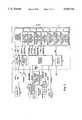
- FIG. 1is a simplified block diagram of a Vehicle Security System
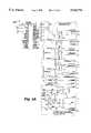
- FIGS. 2 and 2Aare a detailed block diagram of the Vehicle Security System of FIG. 1;
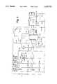
- FIGS. 3 and 3Aare a schematic diagram of the Vehicle Security System of FIG. 1;
- FIG. 4shows exemplary signal waveforms associated with the RF decoder circuit of the Vehicle Security System of FIG. 3;
- FIG. 5is a schematic diagram of the remote control of the Vehicle Security System of FIG. 1;
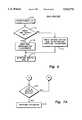
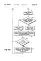
- FIG. 6is a simplified flow diagram of processing steps performed by the Vehicle Security System controller of FIG. 2;
- FIGS. 7 and 7Aare flow diagrams of processing steps performed by the RF decode processor of the Vehicle Security System controller of FIG. 2;
- FIG. 8is a flow diagram of processing steps performed by the Vehicle Security System controller of FIG. 2 while monitoring the system inputs;
- FIGS. 8A and 8Bare a flow diagram of processing steps performed by the arm processor, the alarm processor, and the disarm processor of the Vehicle Security System controller of FIG. 2;
- FIGS. 9 and 9Aare flow diagrams of processing steps performed by the passive arm and pre-arming processor of the Vehicle Security System controller of FIG. 2;
- FIG. 10is a flow diagram of processing steps performed by the Panic/Locator processor of the Vehicle Security System controller of FIG. 2;
- FIG. 11is a flow diagram of processing steps performed by the programming processor of the Vehicle Security System controller of FIG. 2.
- a vehicle security system 10 operable for use with a remote control 40is provided on a car 12.
- the security system 10includes a plurality of sensors for sensing the status of various components associated with the car 12, each providing an output signal indicative of such status.
- a vehicle security system controller 60(FIG. 2) which monitors the sensor output signals (i.e., security system inputs) and provides a first siren control signal when the mode of operation of the system is changed, and a second siren control signal when the system is in an armed mode of operation and a condition consistent with an intrusion is indicated by one of the sensor output signals.
- a siren 48provides a chirp sound having a predetermined volume and duration in response to the first siren control signal and an alarm sound having a second, longer duration in response to the second siren control signal.
- the car 12has parking lights 14, a hood switch 16, a starter 18, a battery 20, an ignition 22, a glove box switch 24, a car door switch 26 (i.e., the state of which indicates whether any of the vehicle doors are open), a car door lock 28, a trunk switch 30, and a dome light 32.
- Each of these conventional car componentsis coupled to the vehicle security system 10, as shown.
- the additional sensor 34is provided to increase the versatility of the vehicle security system 10 and may, for example, comprise a glass break sensor.
- the auxiliary feature 36also enhances the versatility of the security system by permitting a selected function associated with the car 12 to be controlled by the remote control 40.
- the auxiliary feature 36may be a separate feature associated with the car 12, such as a sun/moon roof, an audio system, or a cellular telephone.
- the auxiliary feature 36may be one of the above-mentioned car components, such as the ignition 22 or the trunk switch 30.
- Additional apparatusprovided for use with the vehicle security system 10 and installed on the car 12 includes a perimeter sensor 42, a shock sensor 44, an LED display 46, a siren 48, and a valet switch 50.
- the perimeter sensor 42is a microwave sensor used to detect the presence of objects in the vicinity of the car 12 by microwave signal emission detection.
- the perimeter sensor 42is a "MICROSPHERE” module sold by Whistler, Inc. of Westford, Mass.
- the components associated with the car and with the security system generating output signals which provide inputs to the security system 10are referred to herein generally as sensors. All of the sensors except the battery 20 and the valet switch 50 have output signals, the state of which is indicative of a potential intrusion into the vehicle and will be referred to hereinafter as trigger sensors. Moreover, of these trigger sensors, only selected ones generate output signals capable of causing a full alarm to sound (i.e., capable of causing the second siren control signal to be generated).
- the hood switch 16, glove box switch 24, door switch 26, trunk switch 20, additional sensor 34, the shock sensor 44, and the ignition 22are capable of causing a full alarm condition.
- the shock sensoris capable of causing a full alarm condition, it does so only in response to a subsequent, verifying shock indication as will be described.
- the perimeter sensor 42on the other hand is capable only of causing the first siren control signal (i.e., resulting in a siren chirp) to be generated, in order to warn of a possible intrusion condition.
- the security system 10monitors both the sensor output signals and an RF receiver input for commands from the remote control 40.
- the security system 10is operable in at least four modes: (1) a pre-arming mode; (2) an armed mode; (3) a disarmed mode; and (4) an alarmed mode.
- the system 10is additionally operable in a valet mode, a programming mode, a diagnostic mode, and a panic/locate mode. Each of these modes of operation will be described in greater detail below.
- the remote control 40has an LED 52, a panic/locator control 54, an arm/disarm control 56, and an auxiliary control 58.
- the remote control 40is powered by a battery 104 (FIG. 5) and the LED 52 is activated only when one of the controls 54-58 is actuated. Additionally, the LED 52 provides an indication of a low battery condition. More particularly, if the battery voltage exceeds a predetermined threshold level, then whenever one of the controls 54-58 is actuated, the LED 52 is driven to flash on and off at a relatively rapid rate; whereas, if the battery voltage falls below the predetermined threshold level, the LED 52 is driven to flash on and off at a slower rate whenever one of the controls 54-58 is actuated.
- the battery conditionis also indicated on the LED display 46 located the vehicle 12 (FIG. 1).
- the panic/locator control 54has a dual function: (1) to assist in locating the vehicle; and (2) to provide a personal safety feature.
- a first manner of actuation of the panic/locator control 54such as continuous actuation for less than a predetermined duration such as three seconds
- the siren 48is sounded briefly in order to facilitate locating the car audibly, without causing unnecessary disruption.
- the parking lights 14 and/or the dome light 32may flash on and off simultaneously as the siren 48 is sounded.
- the siren 48in response to a one second continuous actuation of the control 54 with the car ignition 22 turned off, the siren 48 is sounded for a series of three, one second bursts and the parking lights 14 are flashed on and off for three seconds.
- the control 54additionally provides a personal safety feature in response to a second manner of actuation, such as continuous actuation for greater than the predetermined duration.
- the panic, or second manner of actuation of the control 54causes the siren 48 to be sounded for a longer duration than is caused by the locator manner of actuation, in an effort to frighten off a potential assaulter.
- the siren 48in response to actuation of the panic/locator control 54 for four seconds, the siren 48 is sounded indefinitely, until the arm/disarm control 56 is activated (or the system 10 is disarmed without use of the remote 40, as will be described below).
- this featureis operable whether or not the ignition 22 is turned on (contrary to the locate manner of actuation of control 54) and the vehicle starter 18 is not interrupted in response to a panic generated siren control signal (contrary to other manners of activation of the siren 48 in response to an intrusion indicating condition). That is, when the siren 48 is activated in response to an intrusion indication by a trigger sensor, the starter 18 is interrupted to ensure that the intruder cannot start the car 12. However, when the siren 48 is activated in response to a panic manner of actuation of the panic control 54, the car operator may want to flee in the car 12 rapidly. Thus, the starter 18 is operable when the siren 48 is sounded in response to the panic manner of actuation of control 54.
- the arm/disarm control 56 of the remote control 40toggles the operation of the security system 10 between the armed and disarmed modes of operation.
- the security system 10is armed when it is desired to protect the vehicle 12 from unwanted intruders and is disarmed when this protection is not desired.
- the armed and disarmed modes of operationcan be entered and exited without using the remote control 40. More particularly, the armed mode can be entered passively, once a passive arming capability of the system 10 is enabled and a sequence of steps associated with the pre-arming mode of operation is performed, as described below in conjunction with FIGS. 9 and 9A.
- the systemmay be disarmed without use of the remote 40 by a predetermined sequence of commands, such as activating the valet switch 50 and simultaneously executing a predetermined ignition sequence, such as consecutively turning the ignition 22 on, off, on, off, and on.
- the auxiliary control 58is used to remotely activate the auxiliary feature 36 which is operable during both the armed and disarmed modes of operation, as described below.
- the auxiliary featureis the car ignition 22
- the security system 10includes a controller 60 which can be described as including several processors including: an RF decode processor 62, a system arm processor 64, a system disarm processor 66, an alarm processor 68, a panic/locate processor 70, a programming processor 72, and a passive arm and pre-arming processor 74.
- the controller 60may be implemented with various known circuitry, such as the illustrative microprocessor shown in FIG. 3A. The process steps performed by each of the processors 62-74 are described in conjunction with the Figures as indicated in FIGS. 2 and 2A.
- the car battery 20provides +12 volts to a voltage regulator 76 which generates +5 V for use by the vehicle security system circuitry.
- the remote control 40communicates with the security system 10 by RF signal transmission. More particularly, RF signals transmitted by the remote control 40 are received at an RF antenna 79 for coupling to an RF decoder circuit 78.
- the decoder circuit 78converts the received RF signal into a pair of signals RF-DATA, RFDATACO.
- the RF-DATA signalcontains a remote control identifying digital word, referred to hereinafter as a user code, as well as information indicative of actuation of the controls 54-58.
- the RFDATACO signalcontains like information to the RF-DATA signal and is used to verify that the received data corresponds to a predetermined format. In response to receipt of data having the predetermined format, it is determined whether such received data was transmitted by the remote control 40 associated with security system 10 by comparing the received user code with a predetermined, stored user code. Having determined that the received user code corresponds to the stored user code, the data received from the remote control 40 is processed.
- the RF decoder circuit 78is described in greater detail below in conjunction with FIGS. 3 and 7-7A.
- Each of the car ignition 22, hood switch 16, trunk switch 30, glove box switch 24, door switch 26, shock sensor 44, perimeter sensor 42, and valet switch 50is coupled to a sensor trigger circuit 80 which includes signal buffers.
- the sensor trigger circuit 80provides corresponding buffered signals (i.e. IGN-SENS, SHOCK-S, NEG-TRIG, MICRO-MO, VALET, DOOR-INP), respectively, to the security system controller 60.
- buffered signalsi.e. IGN-SENS, SHOCK-S, NEG-TRIG, MICRO-MO, VALET, DOOR-INP
- sensor 34may be tied to the NEGTRIG signal line, along with the hood switch 16, trunk switch 30, and glove box switch 24.
- the system controller 60In response to actuation of the auxiliary control 58 of remote control 40, and receipt of an indication of such control actuation via the RF decoder circuit 78, the system controller 60 provides an AUX control signal to an auxiliary circuit 82, as shown. More particularly, in order to avoid unintentional activation of the auxiliary feature 36, the feature 36 is activated only in response to a predetermined manner of actuation of the control 58, such as two actuations within three seconds.
- the auxiliary circuit 82includes a driver to generate an AUX- output signal for coupling to the auxiliary feature 36 (FIG. 1) to activate such feature.
- siren control signalfor sounding the siren 48. More particularly, the siren control signal is coupled to a siren driver circuit 84, the output of which provides the SIREN signal.
- the siren 48is sounded for a brief duration to provide a chirping sound in response to a first siren control signal when the security system 10 changes mode of operation and is sounded for a longer duration in response to a second siren control signal upon the occurrence of an intrusion indicating condition (i.e., a full alarm condition)
- the first and second siren control signalsare both carried by the SIREN signal line and have varying duration.
- a relay driver circuit 86receives control signals (i.e., LOCK, ULOCK, DOME, and LIGHT) from the system controller 60 and provides corresponding driver signals to relays 88 and the door lock 28, as shown.
- the relays 88provide additional control signals to lock and unlock the door lock 28, as well as providing control signals to activate the parking lights 14 and the dome light 32. With this arrangement, the system controller 60 can control the parking lights 14 and the dome light 32 to flash on and off.
- the car starter 18is also controlled by the system controller 60 and, more particularly, by a STARTER output signal thereof.
- the STARTER output signalis inverted by inverters 90 to provide a STARTER-INTERRUPT control signal to the starter 18. This arrangement permits the controller 60 to disengage the starter 18 upon the detection of an intrusion indicating condition of a trigger sensor output so that the car 12 cannot be started.
- Some of the trigger sensorsi.e., the shock sensor 44, the perimeter sensor 42, and the additional sensor 34 have a power input, a ground input, and an output. In order to preserve power, such sensors may be powered only when the security system 10 is in the armed mode of operation.
- the system controller 60provides an ARMED output signal which is inverted by inverters 90 to provide an ARMED- signal at the ground connection point of each such sensor.
- the ARMED- signalis active during the armed mode of operation to close the power loop to these sensors. In this way, the ARMED- signal "enables" these sensors.
- the ALARMING signalis active during the alarmed mode of operation and may be coupled to devices (not shown) which are advantageously activated during an alarm condition (i.e., a full alarm condition).
- a second sirenlocated in the car 12, may be coupled to the ALARMING signal for activation during an alarm condition.
- the LED display 46 of the vehicle security system 10is a tri-color display having two LEDs, one red and one green, activated to provide a red display, a green display, or an amber display, with the amber display provided by simultaneously activating both the red and green LEDs.
- the display 46is located in the vehicle 12, and may be mounted on the dashboard, to indicate various system conditions such as the present system mode of operation, and to assist in the programming of the system 10, as will be described below.
- the green and red LEDsare controlled by LED-GREEN and LED-RED signals provided by a driver circuit 92 in response to controller output signals LED-G and LED-R, respectively.
- a memory device or circuit 94which receives the controller LED output signals LED-G, LED-R and an additional controller output signal CS, as shown.
- Memory circuit 94monitors and communicates with microcontroller 60 via the LED control signals LED-G, LED-R in response to enablement by the CS signal. With this arrangement, if power to the security system 10 is interrupted, the status of the system (i.e., mode of operation) just preceding the power interruption may be recalled from the memory device 94 and resumed by the controller 60.
- the memory device 94is an EEPROM.
- FIGS. 3 and 3Aa schematic of the vehicle security system 10 is shown to include the voltage regulator 76, RF decoder circuit 78, sensor trigger circuit 80, relay driver circuit 86 with relays 88, inverters 90, and the vehicle security system controller 60. Also shown in FIG. 3A is the LED driver circuit 92, the memory circuit 94, the siren driver circuit 84, and the auxiliary circuit 82. As previously mentioned, voltage regulator 76 provides +5 volts to the security system circuitry, as shown. A first portion 78a of the RF decoder circuit 78 includes a conventional super regenerative receiver.
- a second portion 78b of the RF decoder circuit 78receives the super regenerative decoder output signal at circuit node A, which is coupled to a pair of comparators U4, U6 through capacitors C22, C26, respectively.
- the RF-DATA and the RFDATACO signalsare generated and coupled to the vehicle security system controller 60, as shown.
- the digital wordincludes four status bits, one corresponding to actuation of the arm disarm control 56, one corresponding to actuation of the panic/vehicle locator control 54, one corresponding to the status of the remote control battery, and one corresponding to actuation of the auxiliary control 58.
- the RFDATACO signalis provided to detect when a received digital word represents a transmitted data burst having the predetermined format. Stated differently, RFDATACO is used to distinguish a transmitted data burst from noise received between successive data bursts (i.e., shown in the illustrative RF-DATA and RFDATACO signals of FIG. 4 with diagonal lines). To this end, the time constants associated with the RC networks at the inverting inputs of comparators U4 and U6 differ, with time constant associated with RC network C22, R14 being faster than that associated with RC network C26, R16.
- the capacitively coupled inverting inputs of comparators U4 and U6decay at different rates. Specifically upon such a positive going transition, the inverting input to comparator U4 decays faster than that of comparator U6.
- the transitions of the RFDATACO signalare substantially identical to those of the RF-DATA signal within a particular digital word since the bit rate is relatively high.
- the RFDATACO signalis slower to transition in response to slower data rates, such as the data rate of noise received between data bursts.
- the RFDATACO signalis slower to transition to a logic high state to follow the noise, as shown.
- the time constants of the RC networks at the inverting inputs of comparators U4, U6are selected so that the RFDATACO signal remains low for a predetermined duration, such as three milliseconds, after receipt of a data burst having the predetermined format, while the RF-DATA signal is transitioning in response to noise.
- the RFDATACO signal being in a logic low state for approximately three millisecondsindicates that a remote transmitted data burst having the predetermined format has been received.
- bits of the RF-DATA signal corresponding to the three milliseconds that the RFDATACO signal remained in a logic low stateare removed from memory and the preceding number of bits corresponding to the number of bits in the digital word of the predetermined coding format are processed, as described in greater detail below in conjunction with FIGS. 7-7A.
- the length of the interval during which the RFDATACO signal remains in a logic low state following the three milliseconds after the end of the data burstis indicative of the strength of the received RF data. That is, the longer that the RFDATACO signal remains in a logic low state, the stronger the RF transmission and thus, presumably, the closer the remote control 40 to the vehicle security system 10.
- This signal strength informationmay be used to enhance the remote learning feature of the system described below. Suffice it here to say that upon initial power up of the system 10, an initialization process is performed in which the unique user code associated with the remote control 40 is "learned" by the system 10.
- the RFDATACO signalbe in a logic low state for a predetermined duration before enabling the remote learning capability, in order to ensure that the system learns the user code associated with the corresponding remote control 40.
- the sensor trigger circuit 80includes a plurality of buffers, each one associated with one of the security system input signals and providing corresponding trigger signals to the system controller 60. Specifically, buffer circuits buffer the output signals of the ignition 22, the shock sensor 44, the combined output signal coupled to the hood switch 16, glove box 24, trunk switch 30, and additional sensor 34, the perimeter sensor 42, the valet switch 50, and the door switch 26.
- the system controller 60provides output signals for controlling the parking lights 14, the siren 48, the starter 18, the dome light 32, the door lock 28, the LED display 46, and the auxiliary feature 36, as mentioned above. More particularly, the siren output signal of the controller 60 is coupled to a driver transistor M2 to provide the SIREN control signal, as shown.
- the AUX controller output signalis coupled to a driver transistor Q10 to provide the AUX- control signal to activate the auxiliary feature 36.
- the LED driver circuit 92(FIG.
- 2Aincludes resistors R48-R53 and transistors Q11-Q12 arranged to invert controller output signals LED-G, LED-R to provide corresponding LED control signals LED-GREEN, LED-RED for driving the green and red LEDs.
- the STARTER-INTERRUPT, ALARMING, ARMED signalsare as noted above and specifically, are provided at the outputs of inverters 90a, 90b, and 90c, respectively, the inputs of which are provided by controller output signals STARTER, ALARM, and ARMED, respectively.
- the door lock 28is controlled by relays 96 and 98 which in turn, are activated by controller output signals LOCK and ULOCK.
- the dome light 32is controlled by a relay 100, the activation of which is controlled by controller output signal DOME and the parking lights 14 are controlled by a relay 102, the activation of which is controlled by controller output signal LIGHT.
- Controller 60has an RC network associated therewith for establishing an internal clock signal.
- the RC networkcomprises resistor R43 and capacitor C28 which are arranged to provide the clock signal at the OSC1 port of controller 60.
- the accuracy of the clock signal thus establishedis enhanced by a compensation feature performed during production of the system 10.
- An external reference clock calibration signalsuch as a one KHz signal, is coupled to the perimeter sensor input (i.e., MICRO-MO), or other designated input port of the controller 60.
- Controller 60measures the calibration clock signal and compares it with its nominal value to determine a difference value. The difference value provides a compensation factor used by the controller 60 to compensate for any inaccuracy in the RC generated clock signal.
- a less expensive, RC type of microprocessorcan be used to provide controller 60 without sacrificing the clocking accuracy achievable with a crystal type of microprocessor.
- Switches SW1-SW3provide the auxiliary control 58, the arm/disarm control 56, and the panic/vehicle locator control 54, respectively.
- An additional switch SW4is provided in parallel with switch SW2, such as may be desirable for reasons of product differentiation.
- the remote control 40is powered by a battery 104 which is selectively coupled to the input of a voltage regulator 106 in response to actuation of one of the controls 54-58. That is, the battery voltage is provided at the input of the voltage regulator 106 only when one of the switches SW1-4 is actuated.
- the input portscorresponding to the controls 52-58 and a battery status port, are read.
- the microprocessor input port coupled to the circuit node between resistors R54 and R55corresponds to the status of switch SW1 (i.e., the auxiliary control 58 of FIG. 1)
- the input port coupled to the circuit node between resistors R56 and R57corresponds to the status of switches SW2 and SW4 (i.e., the arm/disarm control 56 of FIG. 1)
- the input port coupled to the circuit node between resistors R58 and R59corresponds to SW3 (i.e., the panic/locate control 54 of FIG. 1).
- the collector electrode of transistor Q15is coupled to the battery status input port to microprocessor 108. More particularly, when one of the switches SW1-4 is actuated, the battery voltage is coupled to a voltage divider comprising resistors R60, R61. If the battery voltage, as divided by resistor divider R60, R61, biases transistor Q15 to be cut off (i.e., corresponding to the battery voltage being greater than a predetermined threshold level) then the battery status input to the microprocessor 108 is in a logic low state, indicating an acceptable battery voltage level.
- the battery status input to remote control microprocessor 108is in a logic high state, indicating that the battery voltage is unacceptably low.
- the switch status and the battery status thus readare combined with a unique user code stored in microprocessor 108 to provide a data output signal of microprocessor 108 which is transmitted to the vehicle security system 10 via RF antenna 107.
- the remote LED 52(see also FIG. 1) is activated whenever one of the controls 54-58 on the remote 40 is actuated and also is activated to indicate a low battery condition. More particularly, if the battery voltage exceeds the threshold level, then whenever one of the controls 54-58 is actuated, the LED 52 is driven to flash at a relatively rapid rate; whereas, when the battery voltage falls below the threshold level, whenever one of the controls 54-58 is actuated, the LED 52 is driven to flash at a slower rate. To this end, LED 52 is driven by an output of microprocessor 108 through a resistor R65, as shown. The battery condition is also indicated on the LED display 46 at vehicle 12 in response to transmission of the battery Status bit shown in FIG. 4.
- the remote control 40has a remote time-out feature whereby the remote control microprocessor 108 enters a reduced power consumption mode in response to one of the switches SW1-4 being continuously actuated for greater than a predetermined duration, such as twenty seconds, consistent with unintentional actuation. More particularly, in response to actuation of one of the switches SW1-4 for longer than twenty seconds, the microprocessor 108 enters a reduced power mode during which reduced power is drawn from the voltage regulator 106 in order to conserve battery power. With this arrangement, battery power is conserved in order to enhance the reliability of the remote control 40.
- a predetermined durationsuch as twenty seconds
- the security system 10is powered in process step 110 by tapping into the constant +12 volt battery source of the car battery 20. Once the security system 10 is powered, it is determined in process step 112 whether the preceding application of power is the first to the security system 10. The determination as to whether the system is in an initial power up routine is achieved by looking at the memory device 94 and reading the states of status bits stored in a register within memory 94. Alternatively, this determination may be based on the LED display 46 which provides a predetermined display arrangement upon initial power up. If the application of power to the security system in step 110 is the first, an initialization procedure is performed in step 116.
- the initialization procedureincludes a predetermined sequence of steps which alert the installer that (1) the system 10 is properly installed; and (2) that a new remote, or remotes must be learned by the system 10.
- the initialization proceduremay comprise turning the ignition 22 on, actuating either the arm/disarm control 56 or the auxiliary control 58 on the remote 40, and then turning the ignition off.
- step 116Learning new remotes is also part of the initialization procedure of step 116 in which the unique user code associated with remote 40 is transmitted by the remote 40, received by the system 10, and stored in the EEPROM 94 (FIG. 3A). Thereafter, in process step 118, the inputs to the security system 110, and specifically to the security system controller 60, are monitored as described below in conjunction with FIG. 8.
- process step 114is performed in which the system status is read by controller 60 from memory device 94 (FIG. 3A) and the system status (i.e., mode of operation) preceding the last interruption of power to the security system is resumed. More particularly, the EEPROM 94 stores the unique user code, the status of the system 10 (i.e., the present mode of operation), and programmable features, described below. In this way, if power to the system is interrupted by an intruder during an alarming mode, once power is reapplied, the system will enter the alarmed mode as is desirable.
- the RF decode algorithm performed by the RF decode processor 62 of controller 60in response to the RF-DATA and RFDATACO signals is shown.
- the algorithmcommences in process step 120, in response to receipt of an RF signal. Thereafter, the RF-DATA signal received by the controller 60 is stored in a memory device, such as a RAM internal to the controller 60.
- process step 124it is determined whether each bit of the received RF-DATA signal has a width within a predetermined range. If the received bit meets the bit width criteria of step 124, the bit is read into a buffer within the controller 60 in process step 126. Alternatively, if the bits do not have the widths within the predetermined range, then the controller 60 returns to process step 122 and continues to receive data, as shown.
- process step 1208it is determined whether the received bits have the format of a transmitted data burst shown in FIG. 4 (i.e., commencing with a start bit, followed by an N bit user code, and further followed by four status bits associated with the remote control functions).
- the way in which this determination is madeis by detecting when the RFDATACO signal has been in a logic low state for a predetermined duration, such as three milliseconds, as described above.
- process step 130is performed.
- process steps 122-128are repeated, as shown.
- M bits of the stored RF-DATA signalare flushed from the buffer, or ignored, in step 130.
- the user code bitsare compared to the learned user code stored in EEPROM 94. If the received user code and the stored user code do not match, process step 142 is performed in which the stored RF-DATA signal is removed from memory, following which the controller 60 returns to process step 122 to receive data, as shown.
- step 138it is next determined in step 138 (FIG. 7A) whether the appropriate user code bits of a subsequently received digital word match the stored user code. More particularly, to ensure that the received data was transmitted by the corresponding remote 40, the process of comparing the received user code to the stored user code is performed twice, on two consecutive received digital words having the predetermined format.
- step 118The inputs to the vehicle security system 10 (i.e., the sensor outputs and the RF input) are monitored in step 118 by reading the ports of the microprocessor 60. As the inputs are monitored in step 118, it is determined whether an auxiliary signal, or command has been received from the remote control 40 in process step 150, whether the passive arming capability has been enabled and activated in process step 152, whether an active arming signal has been received in process step 154, whether a panic/vehicle locate command has been received in process step 156, whether a programming mode command has been received in process step 158, or whether a valet command has been received in step 159.
- the auxiliary signal monitored in step 150is received from the remote control 40 and specifically is received upon actuation of the auxiliary control 58 in the above described manner, such as by two actuations of the control 58 within three seconds.
- the active arm signalis received from the remote control 40 in response to actuation of the arm/disarm control 56 and the panic/vehicle locate command is received from the remote control 40 in response to actuation of the panic/locate control 54.
- the auxiliary feature 36is activated in process 162, as shown.
- the auxiliary featureis operable in either the armed or disarmed modes of operation.
- Conventional security systems having an auxiliary feature capabilityeither disable the auxiliary feature during the armed mode of operation since activation of the feature is likely to trigger the alarm (i.e., such as where the auxiliary feature is the trunk switch 30) or alternatively, the auxiliary feature is operable during the armed mode, but its activation causes the system to disarm, thereby requiring subsequent arming to effectuate vehicle security.
- the controller 60upon receipt of the auxiliary command, determines which sensor(s) is thereby activated and ignores such activated sensor(s) while still protecting the other sensors. For example, where the auxiliary feature 36 is the trunk switch 30 which causes the NEGTRIG signal to be active, the controller ignores the NEGTRIG signal but continues to monitor the shock sensor 44 and the door switch 26. This arrangement is desirable since it prevents unintentional activation of the alarm when utilizing the auxiliary feature and avoids requiring the system to be re-armed in response system de-arming as a result of auxiliary feature activation. If an auxiliary signal is not received in process step 150, then the controller 60 returns to process step 118 in which the system inputs are monitored.
- process step 164If an active arming signal is received in process step 154, then it is determined whether the ignition 22 is on in step 164. If the ignition 22 is on, then process step 166 is subsequently performed in which a modified armed mode of operation is entered, with the doors only protected (i.e., with the vehicle doors locked and the door switch 26 being the only sensor monitored and capable of causing an alarm condition). This feature is desirable since, generally, if the ignition 22 is on and the system is armed, certain ones of the sensors will falsely indicate an intrusion condition (i.e., such as the shock sensor 44 and the perimeter sensor 42). If however in process step 164, it is determined that the ignition 22 is turned off, the armed mode is entered in the manner of process step 168.
- step 168the siren 48 is activated to provide a chirp sound, the parking lights 14 are flashed, the door lock activating signal (i.e., the LOCK signal of FIGS. 2, 2A, 3, and 3A) is held active for a predetermined duration, sufficient to lock the car doors, the LED display 46 is flashed, and the ARMED output signal of the security system 10 is activated. If however in process step 154 the active arm signal is not received, the controller 60 returns to step 118 in which the system inputs are monitored.
- the door lock activating signali.e., the LOCK signal of FIGS. 2, 2A, 3, and 3A
- step 156the panic/locate mode of operation of the security system 10 is entered, the steps of which are described below in conjunction with FIG. 10.
- the controller 60again returns to step 118 in which the system inputs are monitored.
- step 158If a programming mode signal is received in process step 158, the programming mode of operation is entered in which the process steps described below in conjunction with FIG. 11 are performed. Alternatively, if a programming mode signal is not received in step 158, the controller 60 again returns to process step 118 to monitor the system inputs.
- a valet mode commandis received in response to the system being disarmed, the ignition 22 being turned on, and the valet switch 50 being actuated for a predetermined duration during which the panic/locate control 54 is actuated. Entrance into the valet mode of operation, in step 161, is indicated by a predetermined display on LED display 46, such as the amber LED being activated.
- a modified armed modeis entered in which only the sensors coupled to the NEGTRIG signal (FIGS. 2, 2A, 3, and 3A) are protected (i.e., monitored and capable of generating an alarm).
- the arm/disarm control 56 and the aux control 58 of the remote control 40are disabled, but the locate feature of the panic/locate control 54 is operative.
- a violation of the system in the valet modecannot be terminated by activating the arm/disarm control 56, but only by disarming the system without the remote 40.
- step 152it is determined whether the passive arming feature has been enabled and activated.
- Passive armingis a feature whereby certain events or conditions automatically cause the system to enter the armed mode of operation once the feature is enabled.
- the steps comprising the determination of step 152are described below in conjunction with FIGS. 9-9A. Suffice it here to say that if it is determined in step 152 that passive arming has been enabled and is activated, the armed mode of operation is entered in step 222 (see also FIG. 9A). Alternatively, if passive arming is not enabled and activated, the controller 60 returns to step 118, as shown.
- the processing steps of the armed, alarmed, a disarmed modes of operationare shown.
- the armed modeis entered in the manner described above in conjunction with process steps 166, 168, 222, 161 (FIG. 8).
- the armed mode entered in steps 166 and 161differs from the mode entered in steps 168 and 222, as described above.
- the door switch 26only is protected and in the armed mode of step 161, the glove box switch 24, the trunk switch 30, and the hood switch 16 only are protected.
- the armed mode process steps of FIG. 8A and 8Bcorrespond to a "fully" armed mode, as is entered in steps 168 and 222.
- these stepsare modified when the armed modes of steps 161 and 166 are entered in accordance with the ones of the sensors which are protected therein.
- step 171it is determined whether any sensor output is active (i.e., in a state indicative of an intrusion) at a predetermined time after the armed mode is entered, such as four seconds. If a sensor output is active as determined in step 171, step 173 is thereafter performed in which the siren is activated to provide a chirp sound to alert the vehicle operator to the active sensor condition and the output of the active sensor is ignored. Note that the active sensor output is ignored until it is determined in step 173 that such output has transitioned to indicate a secure condition.
- process step 170is performed in which it is determined whether a receiver or sensor input has been received.
- a receiver inputis an RF input to the security system 10 from the remote control 40 and a sensor input is provided by either: the ignition 22, the door switch 26, the shock sensor 44, the trunk switch 30, the glove box switch 24, the hood switch 16, the additional sensor 34, the perimeter sensor 42, or the valet switch 50.
- step 172it is determined whether the input received is a trigger input.
- Trigger inputsare certain ones of the sensor inputs listed above which can cause the siren 48 to be sounded, either with a chirp or a longer duration alarm.
- a trigger inputmay be provided by the ignition 22, the door switch 26, the shock sensor 44, the trunk switch 30, the glove box switch 24, the hood switch 16, the additional sensor 34, or the perimeter sensor 42.
- process step 174is performed in which it is determined whether such received trigger input is a "warn” status input.
- the perimeter sensor 42 and the shock sensor 44provide "warn” status inputs since an indication of an intrusion therefrom does not generate a full alarm.
- the "warn” status indication provided in response to activation of the perimeter sensor 42is a chirp; whereas, the "warn” status indication resulting from activation of the shock sensor 44 is a brief siren blast, such as one cycle of the alarm pattern.
- the shock sensor 44is a "warn” status input in response to at least one indication of a shock and, thereafter, in response to a subsequent shock indication, becomes a trigger input, capable of generating a full alarm.
- shock sensor 44may be a "warn" status input in response to one shock indication and become a trigger input capable of causing a full alarm in response to a second shock indication. If it is determined in process step 174 that the received trigger signal is not a "warn" status input, then the alarm mode is entered in process step 176 during which the siren 48 is sounded for a predetermined duration, such as for thirty seconds. The sounding of the siren in step 176 represents a full alarm condition, described above as occurring in response to the second siren control signal. Thereafter, in process step 178, the occurrence of the potential intrusion is stored in memory device 94, after which the controller 60 returns to process step 170, as shown.
- a receiver inputwas received in step 170 and it is thereafter determined in process step 180 whether the receiver input is a disarm command from the remote control 40. If a disarm command has not been received, then the command received from the remote 40 (i.e., actuation of the aux control 58 or the panic/locate control 54) is processed and acted upon in step 181. Alternatively, if a disarm command is received in step 180, the disarm mode is entered in step 182, as follows.
- process step 184it is determined in process step 184 whether the security system 10 detected a violation or intrusion during the previous armed mode of operation. More specifically, the controller 60 reads the previous system status from memory device 94. If it is determined in step 184 the system 10 was violated during the previous armed mode, process step 186 is performed in which the siren 48 chirps a first predetermined number of times, such as four. Alternatively, if it is determined in step 184 that the system 10 was not violated during the previous armed mode, then the siren 48 chirps a second predetermined, lesser number of times, such as twice. In this way, the vehicle operator is alerted to the previous status of the system.
- This featuregives the car operator an opportunity to seek assistance rather than enter the car, such as may be desirable when the system was previously violated. For example, upon disarming the car while approaching it, if the siren chirps four times indicating that an intruder attempted to enter the car, it may be preferable to seek assistance before approaching the car.
- the parking lights 14are flashed, the door lock controller output signal ULOCK is activated to unlock the car doors, and the dome light controller output signal DOME is activated for a predetermined duration, such as thirty seconds, in process step 190.
- the flashing of the parking lights 14 and the thirty second activation of the dome light 32indicate to the operator that the vehicle 12 has entered a disarmed mode of operation.
- process step 192it is determined whether the ignition 22 has been turned on. If the ignition 22 has been turned on, process step 194 is then performed in which the LED display 46 indicates the status of the intrusion memory 94 and the remote control battery in step 194.
- step 192it is determined in step 192 that the ignition 22 has not been turned on, again the controller 60 returns to process step 170.
- step 202it is determined whether passive arming is enabled, as described below in conjunction with FIG. 11. Suffice it here to say that passive arming is one of the features of the security system 10 that is programmable, either to be enabled or disabled. If passive arming is enabled, the occurrence of one of two sets of conditions causes the system 10 to passively enter the armed mode. In accordance with a first manner of passively arming the vehicle, if a predetermined duration, such as thirty seconds, lapses after the ignition 22 is turned off, then the system 10 passively enters the armed mode.
- a predetermined durationsuch as thirty seconds
- a predetermined durationsuch as thirty seconds, lapses after a remote disarm command is received and the ignition 22 is turned off, then the system passively enters the armed mode of operation. If passive arming is not enabled, as determined in step 202, then the system inputs are monitored in step 18, as shown.
- the pre-arming mode of operationis entered once it is determined in step 202 that passive arming is enabled. That is, the pre-arming mode of operation refers to the steps of FIGS. 9 and 9A by which the system is passively armed.
- the pre-arming mode of operationrefers to the steps of FIGS. 9 and 9A by which the system is passively armed.
- step 204it is determined, in step 204, whether the vehicle ignition 22 is turned off. If the ignition 22 is not turned off, as determined in step 204, then the system inputs are thereafter monitored in step 118. If however the ignition 22 is turned off, it is thereafter determined in step 205 whether the system was disarmed via the remote control 40. If the system was disarmed with the remote 40, then step 206 is performed in accordance with the second manner of passively arming the system. Alternatively, if it is determined in step 205 that the system was not disarmed from the remote 40, step 207 is performed in accordance with the first manner of passively arming the system.
- step 206the dome light 32 is turned on, a passive arming timer (i.e., a time which indicates a predetermined duration such as thirty seconds) is initialized, and a dome light timer (i.e., a second timer which indicates a predetermined duration, such as thirty seconds) is initialized. Thereafter, in step 208, the dome light 32 is turned off, following which the door switch input is monitored in step 210. If it is determined, in process step 212, that the door switch output has transitioned indicating that a door has been opened, then an indicator is set by the controller 60 to ensure that the doors are not locked when the security system 10 is next armed and the passive arming timer is reset, as indicated in step 214.
- a passive arming timeri.e., a time which indicates a predetermined duration such as thirty seconds
- a dome light timeri.e., a second timer which indicates a predetermined duration, such as thirty seconds
- step 212if it is determined in step 212 that the door switch output has not transitioned, indicating that none of the doors has been opened, a different indicator is set by the controller 60 in step 216 to ensure that the vehicle doors are locked when the system 10 is next armed.
- process step 218is performed (FIG. 9A) in which it is determined whether the dome light timer, initialized in step 206, has lapsed. If the dome light timer has not lapsed, then the dome light 32 is turned on in step 220 and the controller 60 returns to process step 208, as shown. Alternatively, if the dome light timer has lapsed, it is thereafter determined in step 219 whether the passive arming timer has lapsed.
- the controller 60returns to step 210, as shown.
- the pre-arming mode of operationterminates and the armed mode of operation is entered in step 222 to passively arm the vehicle.
- the siren 48chirps, the parking lights 14 flash, and, if it was determined in step 212 that the door switch output transitioned and the indicator of step 214 was set, then the door lock controller output signal (i.e., LOCK) is held active for a predetermined period of time to lock the car doors.
- the LED display 46flashes to indicate that the armed mode has been entered and the ARMED output signal of the controller 60 is held active.
- step 207is performed in which the passive arming timer is initialized. Thereafter, in step 209 the door switch input is monitored following which it is determined in step 211 whether the door switch output has transitioned. If the door switch output has transitioned indicating either that a door has been opened or closed, then the controller 60 returns to process step 207 to reset the passive arming timer. If however the door switch output has not transitioned, step 213 is performed in which it is determined whether the passive arming timer has lapsed. If the passive arming timer has lapsed, then the pre-arming mode is terminated and the armed mode is passively entered in step 215.
- step 209the controller 60 returns to step 209, as shown.
- the armed mode of step 215is modified from that of step 222 in that the vehicle doors will not be locked in step 215. That is, recall that by entering the armed mode in step 222, the door may be locked depending on whether a door switch output transitioned as determined in step 212.
- the panic/locate mode of operationcommences in step 230 which corresponds to the monitor inputs step 118 of FIG. 8.
- step 230corresponds to the monitor inputs step 118 of FIG. 8.
- the panic/locate control 54 on the remote control 40has been actuated in the second manner referred to above, namely by continuous actuation for greater than a predetermined duration, such as three seconds.
- Actuation of the panic/locate control 54 in this mannerconstitutes receipt of a panic signal in step 232.
- the panic mode of operationis entered in step 234.
- the siren 48is sounded for a predetermined duration and the parking lights 14 are flashed, as indicated in step 236.
- the siren 48is sounded indefinitely, until the arm/disarm control 56 is activated (or the system 10 is disarmed without the remote). To this end, it is determined in step 238 whether the arm/disarm control 56 of the remote control 40 has been activated. If control 56 has been activated, then the panic alert is turned off by de-activating the siren 48 and the parking lights 14, in process step 240. Alternatively, the controller 60 returns to process step 236 and continues to sound the alarm 48 and flash the parking lights 14. After step 240, the controller 60 returns to the last state, or mode of operation, before the panic signal was received, in step 242, by reading the previous system status from memory device 94.
- process step 246is performed, in which it is determined whether the ignition 22 is turned off. If the ignition 22 is turned off, then the vehicle locate mode of operation is entered in step 248. Thereafter, the siren 48 is sounded intermittently, such as for a series of three, one second siren bursts and the parking lights 14 are flashed, as indicated in step 250. If however, it is determined that the ignition 22 is turned on in step 246, then the controller 60 skips to process step 242 in which the last mode of operation, before the panic/locate control 54 actuation, is resumed. It is desirable to permit the locate mode of operation to be entered only if the ignition 22 is turned off in order to avoid sounding the siren 48 in response to an unintentional actuation of the control 54.
- a programming mode commandincludes disarming the vehicle in step 254 and executing an ignition sequence in step 256. Disarming the vehicle is achieved either by actuating the arm/disarm control 56 of the remote control 40 or by disarming without remote, as described above. Thereafter, in step 256, the operator executes a second predetermined ignition sequence, associated with entering the programming mode.
- One illustrative ignition sequenceis turning the vehicle ignition 22 on, off, on, off, and on.
- a timeris initialized to count down to a predetermined value corresponding to a predetermined duration in process step 258.
- Programming of the system 10consists of sequencing through a plurality of programmable features in response to a sequencing signal, such as may be generated by actuation of the valet switch 50 and selecting a predetermined choice or option associated with a particular feature in response to a selection signal, such as by actuation of the arm/disarm control 56 of the remote control 40.
- a sequencing signalsuch as may be generated by actuation of the valet switch 50 and selecting a predetermined choice or option associated with a particular feature in response to a selection signal, such as by actuation of the arm/disarm control 56 of the remote control 40.
- it is determined in step 260 whether the arm/disarm signal is receivedi.e., whether the control 56 has been actuated. If the arm/disarm signal is not received in step 260, then the security system inputs are again monitored in step 118, as indicated.
- step 264it is next determined in step 264 whether a predetermined duration, such as five seconds, has lapsed from step 258 in which the timer was initialized. If the predetermined duration has lapsed between steps 258 and 264, process step 266 is then performed in which the armed mode of operation is entered (FIG. 8A and 8B). This contingency occurs if the operator decides not to program the system after having disarmed the system in step 254 and executed the specified ignition sequence in step 256. If however, it is determined in step 264 that the predetermined duration has not lapsed, then step 268 is performed and the programming mode of operation is entered.
- a predetermined durationsuch as five seconds
- step 270the programming steps are performed. Specifically, actuation of the valet switch 50 causes the controller 60 to sequence through the plurality of programmable features including: passive arming, shock sensor programming, perimeter sensor programming, audio alarm programming, chirp volume programming, diagnostics programming, and door lock timing. Each of these programmable features has a corresponding plurality of predetermined choices or options associated therewith, the selection of which is achieved by actuation of the arm/disarm control 56 of the remote control 40.
- programming passive armingconsists of selection of enabling passive arming or disabling passive arming.
- programming of the shock sensor and the perimeter sensorconsist of selecting either enablement of disablement thereof.
- the audio alarm programming featurehas six choices associated therewith, each one corresponding to a different sequence of patterns comprising the alarm.
- the chirp volumeis programmed by selecting one of eight options for chirp volume.
- the diagnostics programming featurehas five selections associated therewith corresponding to different diagnostic routines.
- the operability of the sensorscan be verified and the sensitivity of certain sensors tuned.
- Sensors having adjustable sensitivityinclude the perimeter sensor 42 and the shock sensor 44.
- the controller 60 input portsare monitored selectively, to determine whether a particular, monitored input indicates an intrusion condition.
- the input ports to the controller 60are isolated so that the operability of each sensor can be individually verified. For example, when verifying the operation of the shock sensor 44, such as by kicking a tire on the car, isolation of the controller inputs ensures that false operability is not indicated due to triggering the perimeter sensor 42.
- diagnostic routinescorresponds to verifying each of the sensors associated with the car; whereas other diagnostic routines correspond to verifying the operation of a specific one, or ones, of the sensors, such as the shock sensor, the hood switch 16, trunk switch 30, and glove box switch 24, the door switch 26, or the perimeter sensor 42.
- the programmable door lock timingrefers to a predetermined duration for holding the door output signals of the controller 60 active (i.e., the LOCK and ULOCK signals). Programmable door lock timing enables this duration to be customized in accordance with the particular type of door locks on the car 12. For example, cars having vacuum activated door locks require longer to lock than electrical door locks.
- the LED display 46is activated to assist the vehicle operator by indicating the present location of the system within the programming sequence.
- the Table belowillustrates an exemplary manner of indicating the present step within the programming sequence with corresponding sequences of activation of the red LED and the green LED, to provide a red light, a green light, or an amber light, represented in the following Table by R, G, and A, respectively.
- step 272it is determined whether the ignition 22 has been turned off. If the ignition is turned off, then programmed features are stored in memory device 94 in process step 273, as shown. Thereafter, the programming mode is exited in step 274. Note that until the ignition 22 is turned off, the programming steps of step 270 are continuously performed, as shown.
Landscapes
- Engineering & Computer Science (AREA)
- Mechanical Engineering (AREA)
- Burglar Alarm Systems (AREA)
Abstract
Description
TABLE ______________________________________ Programmable LED display Feature Selection sequence ______________________________________ Passive Arming Enable 1A-1G Disable 1A-1RShock Sensor Enable 2A-1G Disable 2A-1RPerimeter Sensor Enable 3A-1G Disable 3A-1R Alarm Selection 1 4A-1G Selection 2 4A-2G Selection 3 4A-3G Selection 4 4A-4G Selection 5 4A-5G Selection 6 4A-6GChirp Volume Volume 1 5A-1G Volume 2 5A-2G Volume 3 5A-3G Volume 4 5A-4G Volume 5 5A-5G Volume 6 5A-6G Volume 7 5A-7G Volume 8 5A-8G Diagnostics Routine 1 - All sensors 6A-1G Routine 2 - Shock sensor 6A-2G Routine 3 - Negative trigger 6A-3G Routine 4 - Door 6A-4G Routine 5 - Perimeter 6A-5G Door Lock Timing one second 7A-1G four seconds 7A-1R ______________________________________
Claims (23)
Priority Applications (2)
| Application Number | Priority Date | Filing Date | Title |
|---|---|---|---|
| US08/139,188US5543776A (en) | 1993-10-19 | 1993-10-19 | Vehicle security system |
| PCT/US1994/011926WO1995011146A1 (en) | 1993-10-19 | 1994-10-19 | Vehicle security system |
Applications Claiming Priority (1)
| Application Number | Priority Date | Filing Date | Title |
|---|---|---|---|
| US08/139,188US5543776A (en) | 1993-10-19 | 1993-10-19 | Vehicle security system |
Publications (1)
| Publication Number | Publication Date |
|---|---|
| US5543776Atrue US5543776A (en) | 1996-08-06 |
Family
ID=22485489
Family Applications (1)
| Application Number | Title | Priority Date | Filing Date |
|---|---|---|---|
| US08/139,188Expired - Fee RelatedUS5543776A (en) | 1993-10-19 | 1993-10-19 | Vehicle security system |
Country Status (2)
| Country | Link |
|---|---|
| US (1) | US5543776A (en) |
| WO (1) | WO1995011146A1 (en) |
Cited By (136)
| Publication number | Priority date | Publication date | Assignee | Title |
|---|---|---|---|---|
| US5619182A (en)* | 1996-01-18 | 1997-04-08 | Robb; Charles L. R. | Configurable color selection circuit for choosing colors of multi-colored leds in toys and secondary automotive flasher/brake indicators |
| US5729199A (en)* | 1996-06-06 | 1998-03-17 | Consolidated Graphic Materials, Inc. | Security system for a metallic enclosure |
| US5739747A (en)* | 1996-01-04 | 1998-04-14 | Flick; Kenneth E. | Vehicle security system including a remote unit that emulates security system condition local indications and related methods |
| US5763957A (en)* | 1996-02-08 | 1998-06-09 | Nissan Motor Co., Ltd. | Vehicular trunk unlatching device having a circuit for disabling an unlatching operation in response to an arming of an anti-theft system |
| US5790065A (en)* | 1997-02-28 | 1998-08-04 | Ford Motor Company | Remote control for vehicular audio systems |
| US5793283A (en)* | 1997-01-21 | 1998-08-11 | Davis; Ronnie | Pager vehicle theft prevention and recovery system |
| US5808375A (en)* | 1995-08-18 | 1998-09-15 | Kiekert Ag | Method of operating an electrical control system for an automotive vehicle having a service-facility mode |
| US5828316A (en)* | 1995-05-12 | 1998-10-27 | Audiovox Corporation | Keyless entry function expander |
| US5864297A (en)* | 1994-12-16 | 1999-01-26 | Chrysler Corporation | Reprogrammable remote keyless entry system |
| US5870019A (en)* | 1996-10-09 | 1999-02-09 | Advance Security Inc. | Remote control vehicle security system issuing in override re-arm feature |
| US5902166A (en)* | 1996-01-18 | 1999-05-11 | Robb; Charles L. R. | Configurable color selection circuit for choosing colors of multi-colored LEDs in toys |
| US5952933A (en)* | 1992-05-22 | 1999-09-14 | Issa; Darrell E. | System having advanced embedded code hopping encryption and learn mode therefor |
| US5969433A (en)* | 1997-04-23 | 1999-10-19 | Maggiora; David Raymond | Theft preventing and deterring system and method using a remote station |
| US5973592A (en)* | 1996-01-04 | 1999-10-26 | Flick; Kenneth E. | Vehicle security system including a remote unit that emulates security system condition local indications and related method |
| US6011321A (en)* | 1998-05-11 | 2000-01-04 | Stancu; Dumitru V | Page receiver security system |
| US6028505A (en)* | 1996-03-27 | 2000-02-22 | Clifford Electronics, Inc. | Electronic vehicle security system with remote control |
| US6100792A (en)* | 1996-05-20 | 2000-08-08 | Alpine Electronics, Inc. | Car security apparatus and car security system |
| US6246315B1 (en)* | 1998-07-23 | 2001-06-12 | Keith A. Thomas | Vehicle alarm |
| US6265988B1 (en)* | 1998-04-06 | 2001-07-24 | Trw Inc. | Apparatus and method for remote convenience message transmission and control utilizing frequency diversity |
| US6288635B1 (en)* | 1999-01-05 | 2001-09-11 | Code Alarm, Inc. | Vehicle security system |
| US20010029524A1 (en)* | 2000-04-11 | 2001-10-11 | Richard Smith | Universal mail wireless e-mail reader |
| US6320498B1 (en)* | 2000-09-22 | 2001-11-20 | Kenneth E. Flick | Vehicle security system with silent arming and/or disarming and associated methods |
| US20010056508A1 (en)* | 2000-05-12 | 2001-12-27 | Kenneth Arneson | Event notification system and method |
| US20010056473A1 (en)* | 1999-04-26 | 2001-12-27 | Kenneth Arneson | Information retrieval system and method |
| US6335679B1 (en) | 1998-07-23 | 2002-01-01 | Keith A. Thomas | Vehicle alarm and pager system |
| US6356827B1 (en)* | 2000-05-30 | 2002-03-12 | Delphi Technologies, Inc. | Auxiliary control with diagnostic capability |
| US6374164B1 (en)* | 1996-07-17 | 2002-04-16 | Volvo Car Corporation | Remote control device for remote operation of a motor vehicle |
| USD456987S1 (en) | 2001-06-01 | 2002-05-14 | Brenda J Kreischer | Combined key chain and car alarm remote |
| US20020119793A1 (en)* | 2001-02-27 | 2002-08-29 | Daniel Hronek | Mobile originated interactive menus via short messaging services |
| US6462648B1 (en)* | 1999-03-13 | 2002-10-08 | Code Systems, Inc. | Vehicle security system |
| US6512462B1 (en)* | 1996-09-27 | 2003-01-28 | Valeo Electronique | Dual function radio frequency remote control system for a motor vehicle |
| US20030080858A1 (en)* | 2001-10-31 | 2003-05-01 | Thompson Peter Gordie | Key detection switch for vehicle entry and security systems |
| USRE38338E1 (en)* | 1995-05-24 | 2003-12-02 | Hitachi, Ltd. | Car electronic control system and method for controlling the same |
| US20040145458A1 (en)* | 2003-01-27 | 2004-07-29 | Audiovox Corporation | Vehicle security system and method for programming an arming delay |
| US20040216940A1 (en)* | 2003-04-11 | 2004-11-04 | Bernhard Forstl | Method and device for increasing the safety of operation of an electrical component |
| US20040253964A1 (en)* | 2003-06-12 | 2004-12-16 | Yinjun Zhu | Mobile based area event handling when currently visited network does not cover area |
| US6891811B1 (en) | 2000-04-18 | 2005-05-10 | Telecommunication Systems Inc. | Short messaging service center mobile-originated to HTTP internet communications |
| US20050110635A1 (en)* | 2003-03-20 | 2005-05-26 | Giermanski James R. | System, methods and computer program products for monitoring transport containers |
| US20050146438A1 (en)* | 2002-04-22 | 2005-07-07 | Giger Robert J. | Remote control with low battery indication |
| US20050151630A1 (en)* | 2004-01-13 | 2005-07-14 | Denso Corporation | Automotive antitheft system |
| US6963272B1 (en)* | 2000-08-29 | 2005-11-08 | Omega Patents, L.L.C. | Vehicle security system shock sensing siren and associated methods |
| US20050253705A1 (en)* | 2004-05-17 | 2005-11-17 | Mitsubishi Jidosha Kogyo Kabushiki Kaisha | Alarm system |
| US7110773B1 (en) | 2000-04-11 | 2006-09-19 | Telecommunication Systems, Inc. | Mobile activity status tracker |
| US20060238314A1 (en)* | 2005-04-20 | 2006-10-26 | Dei Headquarters, Inc. | Security system with multi-power mode remote control communications |
| US20070008085A1 (en)* | 2005-07-07 | 2007-01-11 | Toyota Jidosha Kabushiki Kaisha | Antitheft apparatus |
| US20070061052A1 (en)* | 2005-06-15 | 2007-03-15 | Magnadyne Corporation | Noise profiling for ignition sense |
| US7202789B1 (en) | 2003-02-03 | 2007-04-10 | Ingrid, Inc. | Clip for RFID transponder of a security network |
| US20070277584A1 (en)* | 2005-02-28 | 2007-12-06 | Siemens Aktiengesellschaft | System for Testing the Functionality of a Sensor Device |
| US7424293B2 (en) | 2003-12-02 | 2008-09-09 | Telecommunication Systems, Inc. | User plane location based service using message tunneling to support roaming |
| US7426380B2 (en) | 2002-03-28 | 2008-09-16 | Telecommunication Systems, Inc. | Location derived presence information |
| US7428510B2 (en) | 2000-02-25 | 2008-09-23 | Telecommunication Systems, Inc. | Prepaid short messaging |
| US7430425B2 (en) | 2005-05-17 | 2008-09-30 | Telecommunication Systems, Inc. | Inter-carrier digital message with user data payload service providing phone number only experience |
| US7519654B1 (en) | 2000-11-22 | 2009-04-14 | Telecommunication Systems, Inc. | Web gateway multi-carrier support |
| US7522911B2 (en) | 2000-04-11 | 2009-04-21 | Telecommunication Systems, Inc. | Wireless chat automatic status tracking |
| US7548158B2 (en) | 2005-08-08 | 2009-06-16 | Telecommunication Systems, Inc. | First responder wireless emergency alerting with automatic callback and location triggering |
| US7551066B1 (en)* | 1998-12-21 | 2009-06-23 | Mannesmann Vdo Ag | Method and system for transmitting data for a security system of a motor vehicle |
| US20090167512A1 (en)* | 2007-12-28 | 2009-07-02 | Sony Corporation | Security-feature-equipped on-vehicle device and security-feature control method of on-vehicle device |
| EP1953051A3 (en)* | 2007-02-01 | 2009-07-29 | Denso Corporation | Antitheft device for vehicle |
| USRE41006E1 (en) | 2001-09-05 | 2009-11-24 | Telecommunication Systems, Inc. | Inter-carrier short messaging service providing phone number only experience |
| US7626951B2 (en) | 2005-10-06 | 2009-12-01 | Telecommunication Systems, Inc. | Voice Over Internet Protocol (VoIP) location based conferencing |
| US7629926B2 (en) | 2004-10-15 | 2009-12-08 | Telecommunication Systems, Inc. | Culled satellite ephemeris information for quick, accurate assisted locating satellite location determination for cell site antennas |
| US7640031B2 (en) | 2006-06-22 | 2009-12-29 | Telecommunication Systems, Inc. | Mobile originated interactive menus via short messaging services |
| US7764961B2 (en) | 2003-06-12 | 2010-07-27 | Telecommunication Systems, Inc. | Mobile based area event handling when currently visited network does not cover area |
| US7809382B2 (en) | 2000-04-11 | 2010-10-05 | Telecommunication Systems, Inc. | Short message distribution center |
| US7840208B2 (en) | 1999-10-04 | 2010-11-23 | Telecommunication Systems, Inc. | Intelligent queue for information teleservice messages with superceding updates |
| US7853272B2 (en) | 2001-12-21 | 2010-12-14 | Telecommunication Systems, Inc. | Wireless network tour guide |
| US7903791B2 (en) | 2005-06-13 | 2011-03-08 | Telecommunication Systems, Inc. | Enhanced E911 location information using voice over internet protocol (VoIP) |
| US7907551B2 (en) | 2005-10-06 | 2011-03-15 | Telecommunication Systems, Inc. | Voice over internet protocol (VoIP) location based 911 conferencing |
| US7912446B2 (en) | 2003-12-19 | 2011-03-22 | Telecommunication Systems, Inc. | Solutions for voice over internet protocol (VoIP) 911 location services |
| US7929530B2 (en) | 2007-11-30 | 2011-04-19 | Telecommunication Systems, Inc. | Ancillary data support in session initiation protocol (SIP) messaging |
| US7945026B2 (en) | 2005-05-27 | 2011-05-17 | Telecommunications Systems, Inc. | Voice over internet protocol (VoIP) E911 metro street address guide (MSAG) validation |
| US7949773B2 (en) | 2000-04-12 | 2011-05-24 | Telecommunication Systems, Inc. | Wireless internet gateway |
| US7966013B2 (en) | 2006-11-03 | 2011-06-21 | Telecommunication Systems, Inc. | Roaming gateway enabling location based services (LBS) roaming for user plane in CDMA networks without requiring use of a mobile positioning center (MPC) |
| US7991411B2 (en) | 2004-05-06 | 2011-08-02 | Telecommunication Systems, Inc. | Method to qualify multimedia message content to enable use of a single internet address domain to send messages to both short message service centers and multimedia message service centers |
| US8059789B2 (en) | 2006-02-24 | 2011-11-15 | Telecommunication Systems, Inc. | Automatic location identification (ALI) emergency services pseudo key (ESPK) |
| US8068587B2 (en) | 2008-08-22 | 2011-11-29 | Telecommunication Systems, Inc. | Nationwide table routing of voice over internet protocol (VOIP) emergency calls |
| US8073477B2 (en) | 2000-04-11 | 2011-12-06 | Telecommunication Systems, Inc. | Short message distribution center |
| US8099105B2 (en) | 2006-09-19 | 2012-01-17 | Telecommunication Systems, Inc. | Device based trigger for location push event |
| US8150363B2 (en) | 2006-02-16 | 2012-04-03 | Telecommunication Systems, Inc. | Enhanced E911 network access for call centers |
| US8185087B2 (en) | 2007-09-17 | 2012-05-22 | Telecommunication Systems, Inc. | Emergency 911 data messaging |
| US8195205B2 (en) | 2004-05-06 | 2012-06-05 | Telecommunication Systems, Inc. | Gateway application to support use of a single internet address domain for routing messages to multiple multimedia message service centers |
| US8208605B2 (en) | 2006-05-04 | 2012-06-26 | Telecommunication Systems, Inc. | Extended efficient usage of emergency services keys |
| DE102011104061A1 (en)* | 2011-06-11 | 2012-12-13 | Volkswagen Aktiengesellschaft | Method for activating and/or deactivating valet-parking function in motor car, involves activating valet parking function to inhibit access to lockable region of motor car if control element is in actuated state |
| US8369825B2 (en) | 2003-12-19 | 2013-02-05 | Telecommunication Systems, Inc. | Enhanced E911 network access for a call center using session initiation protocol (SIP) messaging |
| US8385964B2 (en) | 2005-04-04 | 2013-02-26 | Xone, Inc. | Methods and apparatuses for geospatial-based sharing of information by multiple devices |
| US8463284B2 (en) | 2006-07-17 | 2013-06-11 | Telecommunication Systems, Inc. | Short messaging system (SMS) proxy communications to enable location based services in wireless devices |
| US8467320B2 (en) | 2005-10-06 | 2013-06-18 | Telecommunication Systems, Inc. | Voice over internet protocol (VoIP) multi-user conferencing |
| US8660573B2 (en) | 2005-07-19 | 2014-02-25 | Telecommunications Systems, Inc. | Location service requests throttling |
| US8666397B2 (en) | 2002-12-13 | 2014-03-04 | Telecommunication Systems, Inc. | Area event handling when current network does not cover target area |
| US8682321B2 (en) | 2011-02-25 | 2014-03-25 | Telecommunication Systems, Inc. | Mobile internet protocol (IP) location |
| US8688174B2 (en) | 2012-03-13 | 2014-04-01 | Telecommunication Systems, Inc. | Integrated, detachable ear bud device for a wireless phone |
| US8688087B2 (en) | 2010-12-17 | 2014-04-01 | Telecommunication Systems, Inc. | N-dimensional affinity confluencer |
| US8712453B2 (en) | 2008-12-23 | 2014-04-29 | Telecommunication Systems, Inc. | Login security with short messaging |
| US8831556B2 (en) | 2011-09-30 | 2014-09-09 | Telecommunication Systems, Inc. | Unique global identifier header for minimizing prank emergency 911 calls |
| US8867485B2 (en) | 2009-05-05 | 2014-10-21 | Telecommunication Systems, Inc. | Multiple location retrieval function (LRF) network having location continuity |
| US8913983B2 (en) | 2005-05-27 | 2014-12-16 | Telecommunication Systems, Inc. | Voice over internet protocol (VoIP) E911 metro street address guide (MSAG) validation |
| US8929854B2 (en) | 2011-10-27 | 2015-01-06 | Telecommunication Systems, Inc. | Emergency text messaging |
| US8942743B2 (en) | 2010-12-17 | 2015-01-27 | Telecommunication Systems, Inc. | iALERT enhanced alert manager |
| US8954028B2 (en) | 2008-09-25 | 2015-02-10 | Telecommunication Systems, Inc. | Geo-redundant and high reliability commercial mobile alert system (CMAS) |
| US8984591B2 (en) | 2011-12-16 | 2015-03-17 | Telecommunications Systems, Inc. | Authentication via motion of wireless device movement |
| US8983047B2 (en) | 2013-03-20 | 2015-03-17 | Telecommunication Systems, Inc. | Index of suspicion determination for communications request |
| US9088614B2 (en) | 2003-12-19 | 2015-07-21 | Telecommunications Systems, Inc. | User plane location services over session initiation protocol (SIP) |
| US9130963B2 (en) | 2011-04-06 | 2015-09-08 | Telecommunication Systems, Inc. | Ancillary data support in session initiation protocol (SIP) messaging |
| US9154906B2 (en) | 2002-03-28 | 2015-10-06 | Telecommunication Systems, Inc. | Area watcher for wireless network |
| US9160572B2 (en) | 2006-10-17 | 2015-10-13 | Telecommunication Systems, Inc. | Automated location determination to support VoIP E911 using self-surveying techniques for ad hoc wireless network |
| US9161189B2 (en) | 2005-10-18 | 2015-10-13 | Telecommunication Systems, Inc. | Automatic call forwarding to in-vehicle telematics system |
| US9191520B2 (en) | 2010-12-13 | 2015-11-17 | Telecommunication Systems, Inc. | Location services gateway server |
| US9208346B2 (en) | 2012-09-05 | 2015-12-08 | Telecommunication Systems, Inc. | Persona-notitia intellection codifier |
| US9220958B2 (en) | 2002-03-28 | 2015-12-29 | Telecommunications Systems, Inc. | Consequential location derived information |
| US9232062B2 (en) | 2007-02-12 | 2016-01-05 | Telecommunication Systems, Inc. | Mobile automatic location identification (ALI) for first responders |
| US9282451B2 (en) | 2005-09-26 | 2016-03-08 | Telecommunication Systems, Inc. | Automatic location identification (ALI) service requests steering, connection sharing and protocol translation |
| US9294911B2 (en) | 2010-05-10 | 2016-03-22 | Telecommunication Systems, Inc. | Cell-ID translation in a location based system (LBS) |
| US9301191B2 (en) | 2013-09-20 | 2016-03-29 | Telecommunication Systems, Inc. | Quality of service to over the top applications used with VPN |
| US9307372B2 (en) | 2012-03-26 | 2016-04-05 | Telecommunication Systems, Inc. | No responders online |
| US9313638B2 (en) | 2012-08-15 | 2016-04-12 | Telecommunication Systems, Inc. | Device independent caller data access for emergency calls |
| US9313637B2 (en) | 2011-12-05 | 2016-04-12 | Telecommunication Systems, Inc. | Wireless emergency caller profile data delivery over a legacy interface |
| US9338153B2 (en) | 2012-04-11 | 2016-05-10 | Telecommunication Systems, Inc. | Secure distribution of non-privileged authentication credentials |
| US9369294B2 (en) | 2007-12-14 | 2016-06-14 | Telecommunication Systems, Inc. | Reverse 911 using multicast session internet protocol (SIP) conferencing of voice over internet protocol (VoIP) users |
| US9384339B2 (en) | 2012-01-13 | 2016-07-05 | Telecommunication Systems, Inc. | Authenticating cloud computing enabling secure services |
| US9408047B2 (en) | 2013-10-10 | 2016-08-02 | Telecommunication Systems, Inc. | Read acknowledgement interoperability for text messaging and IP messaging |
| US9408046B2 (en) | 2006-10-03 | 2016-08-02 | Telecommunication Systems, Inc. | 911 data messaging |
| US9408034B2 (en) | 2013-09-09 | 2016-08-02 | Telecommunication Systems, Inc. | Extended area event for network based proximity discovery |
| US9456301B2 (en) | 2012-12-11 | 2016-09-27 | Telecommunication Systems, Inc. | Efficient prisoner tracking |
| US9479344B2 (en) | 2011-09-16 | 2016-10-25 | Telecommunication Systems, Inc. | Anonymous voice conversation |
| US9479897B2 (en) | 2013-10-03 | 2016-10-25 | Telecommunication Systems, Inc. | SUPL-WiFi access point controller location based services for WiFi enabled mobile devices |
| US9516104B2 (en) | 2013-09-11 | 2016-12-06 | Telecommunication Systems, Inc. | Intelligent load balancer enhanced routing |
| US9519888B2 (en) | 2006-05-08 | 2016-12-13 | Telecommunication Systems, Inc. | End use transparent email attachment handling to overcome size and attachment policy barriers |
| US9544260B2 (en) | 2012-03-26 | 2017-01-10 | Telecommunication Systems, Inc. | Rapid assignment dynamic ownership queue |
| US9599717B2 (en) | 2002-03-28 | 2017-03-21 | Telecommunication Systems, Inc. | Wireless telecommunications location based services scheme selection |
| US9744904B1 (en) | 2016-02-09 | 2017-08-29 | Corinne Tolliver | Vehicle alarm |
| US20170327080A1 (en)* | 2016-05-12 | 2017-11-16 | Ford Global Technologies, Llc | Vehicle Network Communication Protection |
| US9922547B2 (en)* | 1998-07-22 | 2018-03-20 | Touchtunes Music Corporation | Remote control unit for activating and deactivating means for payment and for displaying payment status |
| US10720045B2 (en) | 2018-01-04 | 2020-07-21 | Directed, Llc | Remote vehicle system configuration, control, and telematics |
| CN114179748A (en)* | 2021-12-02 | 2022-03-15 | 深圳市源立信照明科技有限公司 | Vehicle-mounted alarm device and control method thereof |
| US11420592B2 (en)* | 2019-08-07 | 2022-08-23 | Keep Technologies, Inc. | Multimodal intrusion detection |
| CN115158223A (en)* | 2022-07-26 | 2022-10-11 | 东风柳州汽车有限公司 | Anti-disassembly control method, device and system for vehicle controller |
Families Citing this family (5)
| Publication number | Priority date | Publication date | Assignee | Title |
|---|---|---|---|---|
| US5717387A (en)* | 1990-01-19 | 1998-02-10 | Prince Corporation | Remote vehicle programming system |
| FR2733955B1 (en)* | 1995-05-11 | 1997-07-04 | Alehyane Najib | ANTI-THEFT SYSTEM OF A MOTOR VEHICLE |
| BE1009585A3 (en)* | 1995-09-05 | 1997-05-06 | Bmp & Partners S A | Device for guarding a means of transport |
| GB2344442A (en)* | 1998-12-04 | 2000-06-07 | Rover Group | Vehicle |
| US20020140570A1 (en)* | 2001-03-30 | 2002-10-03 | Joseph Ploucha | RKE key fob dual function response algorithm |
Citations (44)
| Publication number | Priority date | Publication date | Assignee | Title |
|---|---|---|---|---|
| US3659265A (en)* | 1970-05-27 | 1972-04-25 | Richard F Eversull | Anti-theft detector and alarm systems for vehicles |
| US3671934A (en)* | 1970-11-02 | 1972-06-20 | Rudor M Teich | Automobile theft alarm for detecting unauthorized energization of resistive load |
| US3710317A (en)* | 1971-05-19 | 1973-01-09 | Educated Vehicle Syst Inc | Auto alarm system |
| US3740713A (en)* | 1970-11-02 | 1973-06-19 | R Teich | Automobile theft alarm with ignition controlled automatic arming means |
| US3829829A (en)* | 1972-01-12 | 1974-08-13 | R Teich | Automobile theft alarm with ignition controlled automatic arming means |
| US3868518A (en)* | 1972-01-12 | 1975-02-25 | Rudor M Teich | Automobile theft alarm with ignition controlled automatic arming means |
| US3936673A (en)* | 1975-02-24 | 1976-02-03 | Kelly John F | Auto door lock alarm |
| US3956732A (en)* | 1972-01-12 | 1976-05-11 | Teich Rudor M | Automobile theft alarm with ignition controlled automatic arming means |
| US4032909A (en)* | 1975-07-07 | 1977-06-28 | Eugene E. Karsten | Arrangement for testing an alarm system and method |
| US4067000A (en)* | 1976-05-28 | 1978-01-03 | Rca Corporation | Remote control transmitter with an audible battery life indicator |
| US4158874A (en)* | 1976-07-28 | 1979-06-19 | C.P.P.L., Inc. | Safety interlock system |
| US4232288A (en)* | 1977-08-23 | 1980-11-04 | Masterman Raymond J | Vehicle alarm |
| US4291296A (en)* | 1980-02-28 | 1981-09-22 | Seifers Monte G | Engine disabling |
| US4320382A (en)* | 1980-08-04 | 1982-03-16 | Roman Industries, Inc. | Automotive alarm |
| US4361827A (en)* | 1980-06-05 | 1982-11-30 | Wico Corporation | Vehicle alarm system |
| US4430685A (en)* | 1976-07-28 | 1984-02-07 | Ellsberg Thomas R | Vehicle lock release mechanism operable with a safety interlock system |
| US4479110A (en)* | 1982-01-18 | 1984-10-23 | Cipri Teno P | Automobile burglar alarm and arming circuit for same |
| US4523178A (en)* | 1982-02-22 | 1985-06-11 | Fulhorst George E | Wireless alarm system in conjunction with at least one vehicle |
| US4543569A (en)* | 1983-05-12 | 1985-09-24 | Audiopro Marketing | Vehicular alarm triggering system |
| US4578671A (en)* | 1984-12-05 | 1986-03-25 | International Business Machines Corp. | Remote indicating low battery voltage enunciator method and apparatus |
| US4635035A (en)* | 1984-03-20 | 1987-01-06 | Moshe Ratzabi | Vehicle automatic switching burglar alarm |
| US4672224A (en)* | 1985-03-20 | 1987-06-09 | Low Shy Kong | Composite automatic control system for vehicle engine with theft prevention circuit |
| US4673921A (en)* | 1984-07-20 | 1987-06-16 | Nippondenso Co., Ltd. | Apparatus for finding the location of a car within a vast area |
| US4689603A (en)* | 1986-03-31 | 1987-08-25 | Conigliaro Thomas S | Vehicle ignition and alarm system |
| US4740775A (en)* | 1980-01-28 | 1988-04-26 | Reese Price | Automobile burglar alarm |
| US4743336A (en)* | 1985-11-18 | 1988-05-10 | Peter Lisec | Device for mounting flexible spacers on glass sheets |
| US4761631A (en)* | 1987-05-14 | 1988-08-02 | Hwang Shih Ming | Main battery disconnection alarm and headlight warning circuit |
| US4796010A (en)* | 1986-07-28 | 1989-01-03 | Bland Robert T | Intrusion alarm and automatic illumination system |
| US4821309A (en)* | 1985-07-09 | 1989-04-11 | Alpine Electronics Inc. | Method of alarm to prevent vehicle thefts |
| US4845464A (en)* | 1988-08-09 | 1989-07-04 | Clifford Electronics, Inc. | Programmable sensor apparatus |
| US4866417A (en)* | 1987-04-24 | 1989-09-12 | Specific Cruise Systems, Inc. | Automobile intruder alarm system |
| US4887065A (en)* | 1987-10-30 | 1989-12-12 | Daimler-Benz Ag | Control system for a combined central locking and burglar alarm system for vehicles |
| US4887064A (en)* | 1987-12-28 | 1989-12-12 | Clifford Electronics, Inc. | Multi-featured security system with self-diagnostic capability |
| US4905271A (en)* | 1985-07-09 | 1990-02-27 | Alpine Electronics Inc. | Method of preventing auto theft |
| US4922224A (en)* | 1987-12-28 | 1990-05-01 | Clifford Electronics, Inc. | Electronic vehicle security system |
| US4926160A (en)* | 1988-08-12 | 1990-05-15 | Hwang Shih Ming | Means for controlling power door locks with an automobile burglar alarm |
| US4963856A (en)* | 1987-04-03 | 1990-10-16 | Mazda Motor Corporation | Theft deterrent system |
| US5019803A (en)* | 1987-12-02 | 1991-05-28 | Morris Maram | Detector units |
| US5049867A (en)* | 1988-11-30 | 1991-09-17 | Code-Alarm, Inc. | Vehicle security apparatus |
| US5079538A (en)* | 1987-04-24 | 1992-01-07 | Specific Cruise Systems, Inc. | Automobile intruder alarm system |
| US5081667A (en)* | 1989-05-01 | 1992-01-14 | Clifford Electronics, Inc. | System for integrating a cellular telephone with a vehicle security system |
| US5117217A (en)* | 1987-01-21 | 1992-05-26 | Electronic Security Products Of California | Alarm system for sensing and vocally warning a person to step back from a protected object |
| US5146215A (en)* | 1987-09-08 | 1992-09-08 | Clifford Electronics, Inc. | Electronically programmable remote control for vehicle security system |
| US5157375A (en)* | 1987-12-28 | 1992-10-20 | Clifford Electronics, Inc. | Electronic vehicle security system |
- 1993
- 1993-10-19USUS08/139,188patent/US5543776A/ennot_activeExpired - Fee Related
- 1994
- 1994-10-19WOPCT/US1994/011926patent/WO1995011146A1/enactiveApplication Filing
Patent Citations (45)
| Publication number | Priority date | Publication date | Assignee | Title |
|---|---|---|---|---|
| US3659265A (en)* | 1970-05-27 | 1972-04-25 | Richard F Eversull | Anti-theft detector and alarm systems for vehicles |
| US3671934A (en)* | 1970-11-02 | 1972-06-20 | Rudor M Teich | Automobile theft alarm for detecting unauthorized energization of resistive load |
| US3740713A (en)* | 1970-11-02 | 1973-06-19 | R Teich | Automobile theft alarm with ignition controlled automatic arming means |
| US3710317A (en)* | 1971-05-19 | 1973-01-09 | Educated Vehicle Syst Inc | Auto alarm system |
| US3829829A (en)* | 1972-01-12 | 1974-08-13 | R Teich | Automobile theft alarm with ignition controlled automatic arming means |
| US3868518A (en)* | 1972-01-12 | 1975-02-25 | Rudor M Teich | Automobile theft alarm with ignition controlled automatic arming means |
| US3956732A (en)* | 1972-01-12 | 1976-05-11 | Teich Rudor M | Automobile theft alarm with ignition controlled automatic arming means |
| US3936673A (en)* | 1975-02-24 | 1976-02-03 | Kelly John F | Auto door lock alarm |
| US4032909A (en)* | 1975-07-07 | 1977-06-28 | Eugene E. Karsten | Arrangement for testing an alarm system and method |
| US4067000A (en)* | 1976-05-28 | 1978-01-03 | Rca Corporation | Remote control transmitter with an audible battery life indicator |
| US4158874A (en)* | 1976-07-28 | 1979-06-19 | C.P.P.L., Inc. | Safety interlock system |
| US4430685A (en)* | 1976-07-28 | 1984-02-07 | Ellsberg Thomas R | Vehicle lock release mechanism operable with a safety interlock system |
| US4232288A (en)* | 1977-08-23 | 1980-11-04 | Masterman Raymond J | Vehicle alarm |
| US4740775B1 (en)* | 1980-01-28 | 1993-03-30 | Price Reese | |
| US4740775A (en)* | 1980-01-28 | 1988-04-26 | Reese Price | Automobile burglar alarm |
| US4291296A (en)* | 1980-02-28 | 1981-09-22 | Seifers Monte G | Engine disabling |
| US4361827A (en)* | 1980-06-05 | 1982-11-30 | Wico Corporation | Vehicle alarm system |
| US4320382A (en)* | 1980-08-04 | 1982-03-16 | Roman Industries, Inc. | Automotive alarm |
| US4479110A (en)* | 1982-01-18 | 1984-10-23 | Cipri Teno P | Automobile burglar alarm and arming circuit for same |
| US4523178A (en)* | 1982-02-22 | 1985-06-11 | Fulhorst George E | Wireless alarm system in conjunction with at least one vehicle |
| US4543569A (en)* | 1983-05-12 | 1985-09-24 | Audiopro Marketing | Vehicular alarm triggering system |
| US4635035A (en)* | 1984-03-20 | 1987-01-06 | Moshe Ratzabi | Vehicle automatic switching burglar alarm |
| US4673921A (en)* | 1984-07-20 | 1987-06-16 | Nippondenso Co., Ltd. | Apparatus for finding the location of a car within a vast area |
| US4578671A (en)* | 1984-12-05 | 1986-03-25 | International Business Machines Corp. | Remote indicating low battery voltage enunciator method and apparatus |
| US4672224A (en)* | 1985-03-20 | 1987-06-09 | Low Shy Kong | Composite automatic control system for vehicle engine with theft prevention circuit |
| US4905271A (en)* | 1985-07-09 | 1990-02-27 | Alpine Electronics Inc. | Method of preventing auto theft |
| US4821309A (en)* | 1985-07-09 | 1989-04-11 | Alpine Electronics Inc. | Method of alarm to prevent vehicle thefts |
| US4743336A (en)* | 1985-11-18 | 1988-05-10 | Peter Lisec | Device for mounting flexible spacers on glass sheets |
| US4689603A (en)* | 1986-03-31 | 1987-08-25 | Conigliaro Thomas S | Vehicle ignition and alarm system |
| US4796010A (en)* | 1986-07-28 | 1989-01-03 | Bland Robert T | Intrusion alarm and automatic illumination system |
| US5117217A (en)* | 1987-01-21 | 1992-05-26 | Electronic Security Products Of California | Alarm system for sensing and vocally warning a person to step back from a protected object |
| US4963856A (en)* | 1987-04-03 | 1990-10-16 | Mazda Motor Corporation | Theft deterrent system |
| US5079538A (en)* | 1987-04-24 | 1992-01-07 | Specific Cruise Systems, Inc. | Automobile intruder alarm system |
| US4866417A (en)* | 1987-04-24 | 1989-09-12 | Specific Cruise Systems, Inc. | Automobile intruder alarm system |
| US4761631A (en)* | 1987-05-14 | 1988-08-02 | Hwang Shih Ming | Main battery disconnection alarm and headlight warning circuit |
| US5146215A (en)* | 1987-09-08 | 1992-09-08 | Clifford Electronics, Inc. | Electronically programmable remote control for vehicle security system |
| US4887065A (en)* | 1987-10-30 | 1989-12-12 | Daimler-Benz Ag | Control system for a combined central locking and burglar alarm system for vehicles |
| US5019803A (en)* | 1987-12-02 | 1991-05-28 | Morris Maram | Detector units |
| US4922224A (en)* | 1987-12-28 | 1990-05-01 | Clifford Electronics, Inc. | Electronic vehicle security system |
| US4887064A (en)* | 1987-12-28 | 1989-12-12 | Clifford Electronics, Inc. | Multi-featured security system with self-diagnostic capability |
| US5157375A (en)* | 1987-12-28 | 1992-10-20 | Clifford Electronics, Inc. | Electronic vehicle security system |
| US4845464A (en)* | 1988-08-09 | 1989-07-04 | Clifford Electronics, Inc. | Programmable sensor apparatus |
| US4926160A (en)* | 1988-08-12 | 1990-05-15 | Hwang Shih Ming | Means for controlling power door locks with an automobile burglar alarm |
| US5049867A (en)* | 1988-11-30 | 1991-09-17 | Code-Alarm, Inc. | Vehicle security apparatus |
| US5081667A (en)* | 1989-05-01 | 1992-01-14 | Clifford Electronics, Inc. | System for integrating a cellular telephone with a vehicle security system |
Non-Patent Citations (4)
| Title |
|---|
| Product Liberature entitled "A'safe Car Security Products (General Catalog)", undated, of AutoMicro Technology Inc., No. 6, Alley 8, Lane 214, Pao-ping Road, Yuong-Ho City, Taipei, Taiwan, R.O.C., consisting of ten pages, received Mar. 1994. |
| Product Liberature entitled A safe Car Security Products (General Catalog) , undated, of AutoMicro Technology Inc., No. 6, Alley 8, Lane 214, Pao ping Road, Yuong Ho City, Taipei, Taiwan, R.O.C., consisting of ten pages, received Mar. 1994.* |
| Product Literature entitled "A'safe Car Security System--Microprocessor & Wireless Design", undated, of AutoMicro Technology Inc., No. 6, Alley 8, Lane 214, Pao-Ping Rd., Yuong-Ho City, Taipei, Taiwan, R.O.C., consisting of four unnumbered pages, Received Mar. 1994. |
| Product Literature entitled A safe Car Security System Microprocessor & Wireless Design , undated, of AutoMicro Technology Inc., No. 6, Alley 8, Lane 214, Pao Ping Rd., Yuong Ho City, Taipei, Taiwan, R.O.C., consisting of four unnumbered pages, Received Mar. 1994.* |
Cited By (256)
| Publication number | Priority date | Publication date | Assignee | Title |
|---|---|---|---|---|
| US5952933A (en)* | 1992-05-22 | 1999-09-14 | Issa; Darrell E. | System having advanced embedded code hopping encryption and learn mode therefor |
| US5864297A (en)* | 1994-12-16 | 1999-01-26 | Chrysler Corporation | Reprogrammable remote keyless entry system |
| US5828316A (en)* | 1995-05-12 | 1998-10-27 | Audiovox Corporation | Keyless entry function expander |
| USRE38338E1 (en)* | 1995-05-24 | 2003-12-02 | Hitachi, Ltd. | Car electronic control system and method for controlling the same |
| US5808375A (en)* | 1995-08-18 | 1998-09-15 | Kiekert Ag | Method of operating an electrical control system for an automotive vehicle having a service-facility mode |
| US5973592A (en)* | 1996-01-04 | 1999-10-26 | Flick; Kenneth E. | Vehicle security system including a remote unit that emulates security system condition local indications and related method |
| US5739747A (en)* | 1996-01-04 | 1998-04-14 | Flick; Kenneth E. | Vehicle security system including a remote unit that emulates security system condition local indications and related methods |
| US5619182A (en)* | 1996-01-18 | 1997-04-08 | Robb; Charles L. R. | Configurable color selection circuit for choosing colors of multi-colored leds in toys and secondary automotive flasher/brake indicators |
| US5902166A (en)* | 1996-01-18 | 1999-05-11 | Robb; Charles L. R. | Configurable color selection circuit for choosing colors of multi-colored LEDs in toys |
| US5763957A (en)* | 1996-02-08 | 1998-06-09 | Nissan Motor Co., Ltd. | Vehicular trunk unlatching device having a circuit for disabling an unlatching operation in response to an arming of an anti-theft system |
| US6028505A (en)* | 1996-03-27 | 2000-02-22 | Clifford Electronics, Inc. | Electronic vehicle security system with remote control |
| US6100792A (en)* | 1996-05-20 | 2000-08-08 | Alpine Electronics, Inc. | Car security apparatus and car security system |
| US5729199A (en)* | 1996-06-06 | 1998-03-17 | Consolidated Graphic Materials, Inc. | Security system for a metallic enclosure |
| US6374164B1 (en)* | 1996-07-17 | 2002-04-16 | Volvo Car Corporation | Remote control device for remote operation of a motor vehicle |
| US6512462B1 (en)* | 1996-09-27 | 2003-01-28 | Valeo Electronique | Dual function radio frequency remote control system for a motor vehicle |
| US5870019A (en)* | 1996-10-09 | 1999-02-09 | Advance Security Inc. | Remote control vehicle security system issuing in override re-arm feature |
| US5793283A (en)* | 1997-01-21 | 1998-08-11 | Davis; Ronnie | Pager vehicle theft prevention and recovery system |
| US5790065A (en)* | 1997-02-28 | 1998-08-04 | Ford Motor Company | Remote control for vehicular audio systems |
| US5969433A (en)* | 1997-04-23 | 1999-10-19 | Maggiora; David Raymond | Theft preventing and deterring system and method using a remote station |
| US6265988B1 (en)* | 1998-04-06 | 2001-07-24 | Trw Inc. | Apparatus and method for remote convenience message transmission and control utilizing frequency diversity |
| US6011321A (en)* | 1998-05-11 | 2000-01-04 | Stancu; Dumitru V | Page receiver security system |
| US9922547B2 (en)* | 1998-07-22 | 2018-03-20 | Touchtunes Music Corporation | Remote control unit for activating and deactivating means for payment and for displaying payment status |
| US6246315B1 (en)* | 1998-07-23 | 2001-06-12 | Keith A. Thomas | Vehicle alarm |
| US6335679B1 (en) | 1998-07-23 | 2002-01-01 | Keith A. Thomas | Vehicle alarm and pager system |
| US7551066B1 (en)* | 1998-12-21 | 2009-06-23 | Mannesmann Vdo Ag | Method and system for transmitting data for a security system of a motor vehicle |
| US6288635B1 (en)* | 1999-01-05 | 2001-09-11 | Code Alarm, Inc. | Vehicle security system |
| US6462648B1 (en)* | 1999-03-13 | 2002-10-08 | Code Systems, Inc. | Vehicle security system |
| US20010056473A1 (en)* | 1999-04-26 | 2001-12-27 | Kenneth Arneson | Information retrieval system and method |
| US7844285B2 (en) | 1999-10-04 | 2010-11-30 | Telecommunication Systems, Inc. | Intelligent queue for information teleservice messages with superseding updates |
| US8244218B2 (en) | 1999-10-04 | 2012-08-14 | Telecommunication Systems, Inc. | Intelligent queue for information teleservice messages with superceding updates |
| US8019368B2 (en) | 1999-10-04 | 2011-09-13 | Telecommunication Systems, Inc. | Intelligent queue for information teleservice messages with superceding updates |
| US7840208B2 (en) | 1999-10-04 | 2010-11-23 | Telecommunication Systems, Inc. | Intelligent queue for information teleservice messages with superceding updates |
| US7428510B2 (en) | 2000-02-25 | 2008-09-23 | Telecommunication Systems, Inc. | Prepaid short messaging |
| US7853511B2 (en) | 2000-02-25 | 2010-12-14 | Telecommunication Systems, Inc. | Prepaid short messaging |
| US8060429B2 (en) | 2000-02-25 | 2011-11-15 | Telecommunication Systems, Inc. | Prepaid short messaging |
| US8175953B1 (en) | 2000-02-25 | 2012-05-08 | Telecommunication Systems, Inc. | Prepaid short messaging |
| US8738496B2 (en) | 2000-02-25 | 2014-05-27 | Telecommunication Systems, Inc. | Prepaid short messaging |
| US8244220B2 (en) | 2000-04-11 | 2012-08-14 | Telecommunication Systems, Inc. | Wireless chat automatic status tracking |
| US7522911B2 (en) | 2000-04-11 | 2009-04-21 | Telecommunication Systems, Inc. | Wireless chat automatic status tracking |
| US7809382B2 (en) | 2000-04-11 | 2010-10-05 | Telecommunication Systems, Inc. | Short message distribution center |
| US6871215B2 (en) | 2000-04-11 | 2005-03-22 | Telecommunication Systems Inc. | Universal mail wireless e-mail reader |
| US7809359B2 (en) | 2000-04-11 | 2010-10-05 | Telecommunication Systems, Inc. | Wireless chat automatic status tracking |
| US20010029524A1 (en)* | 2000-04-11 | 2001-10-11 | Richard Smith | Universal mail wireless e-mail reader |
| US9241040B2 (en) | 2000-04-11 | 2016-01-19 | Telecommunication Systems, Inc. | Mobile activity status tracker |
| US7894825B2 (en) | 2000-04-11 | 2011-02-22 | Telecommunication Systems, Inc. | Mobile activity status tracker |
| US7110773B1 (en) | 2000-04-11 | 2006-09-19 | Telecommunication Systems, Inc. | Mobile activity status tracker |
| US7894797B2 (en) | 2000-04-11 | 2011-02-22 | Telecommunication Systems, Inc. | Wireless chat automatic status signaling |
| US9467844B2 (en) | 2000-04-11 | 2016-10-11 | Telecommunication Systems, Inc. | Mobile activity status tracker |
| US8265673B2 (en) | 2000-04-11 | 2012-09-11 | Telecommunication Systems, Inc. | Short message distribution center |
| US8073477B2 (en) | 2000-04-11 | 2011-12-06 | Telecommunication Systems, Inc. | Short message distribution center |
| US8577339B2 (en) | 2000-04-11 | 2013-11-05 | Telecommunication Systems, Inc. | Wireless chat automatic status signaling |
| US7860068B2 (en) | 2000-04-11 | 2010-12-28 | Telecommunication Systems, Inc. | Intelligent delivery agent for short message distribution center |
| US7949773B2 (en) | 2000-04-12 | 2011-05-24 | Telecommunication Systems, Inc. | Wireless internet gateway |
| US8260329B2 (en) | 2000-04-18 | 2012-09-04 | Telecommunication Systems, Inc. | Mobile-originated to HTTP communications |
| US8750183B2 (en) | 2000-04-18 | 2014-06-10 | Patent Monetization Associates, L.P. | Mobile-originated to HTTP communications |
| US7355990B2 (en) | 2000-04-18 | 2008-04-08 | Telecommunication Systems, Inc. | Mobile-originated to HTTP internet communications |
| US6891811B1 (en) | 2000-04-18 | 2005-05-10 | Telecommunication Systems Inc. | Short messaging service center mobile-originated to HTTP internet communications |
| US9172821B2 (en) | 2000-04-25 | 2015-10-27 | Telecommunication Systems, Inc. | Wireless internet gateway limiting message distribution |
| US9218229B2 (en) | 2000-05-12 | 2015-12-22 | Telecommunication Systems, Inc. | Event notification system and method |
| US20010056508A1 (en)* | 2000-05-12 | 2001-12-27 | Kenneth Arneson | Event notification system and method |
| US20090077188A1 (en)* | 2000-05-12 | 2009-03-19 | Kenneth Arneson | Event notification system and method |
| US6356827B1 (en)* | 2000-05-30 | 2002-03-12 | Delphi Technologies, Inc. | Auxiliary control with diagnostic capability |
| US6963272B1 (en)* | 2000-08-29 | 2005-11-08 | Omega Patents, L.L.C. | Vehicle security system shock sensing siren and associated methods |
| US6320498B1 (en)* | 2000-09-22 | 2001-11-20 | Kenneth E. Flick | Vehicle security system with silent arming and/or disarming and associated methods |
| US7519654B1 (en) | 2000-11-22 | 2009-04-14 | Telecommunication Systems, Inc. | Web gateway multi-carrier support |
| US9002951B2 (en) | 2000-11-22 | 2015-04-07 | Telecommunication Systems, Inc. | Web gateway multi-carrier support |
| US7933615B2 (en) | 2001-02-27 | 2011-04-26 | Telecommunication Systems, Inc. | Mobile originated interactive menus via short messaging services method |
| US7127264B2 (en) | 2001-02-27 | 2006-10-24 | Telecommunication Systems, Inc. | Mobile originated interactive menus via short messaging services |
| US20020119793A1 (en)* | 2001-02-27 | 2002-08-29 | Daniel Hronek | Mobile originated interactive menus via short messaging services |
| USD456987S1 (en) | 2001-06-01 | 2002-05-14 | Brenda J Kreischer | Combined key chain and car alarm remote |
| US8682362B2 (en) | 2001-09-05 | 2014-03-25 | Telecommunication Systems, Inc. | Inter-carrier messaging service providing phone number only experience |
| US8483729B2 (en) | 2001-09-05 | 2013-07-09 | Telecommunication Systems, Inc. | Inter-carrier messaging service providing phone number only experience |
| USRE41006E1 (en) | 2001-09-05 | 2009-11-24 | Telecommunication Systems, Inc. | Inter-carrier short messaging service providing phone number only experience |
| US7890127B2 (en) | 2001-09-05 | 2011-02-15 | Telecommunication Systems, Inc. | Inter-carrier messaging service providing phone number only experience |
| US20030080858A1 (en)* | 2001-10-31 | 2003-05-01 | Thompson Peter Gordie | Key detection switch for vehicle entry and security systems |
| US6859138B2 (en)* | 2001-10-31 | 2005-02-22 | General Motors Corporation | Key detection switch for vehicle entry and security systems |
| US7853272B2 (en) | 2001-12-21 | 2010-12-14 | Telecommunication Systems, Inc. | Wireless network tour guide |
| US7426380B2 (en) | 2002-03-28 | 2008-09-16 | Telecommunication Systems, Inc. | Location derived presence information |
| US9154906B2 (en) | 2002-03-28 | 2015-10-06 | Telecommunication Systems, Inc. | Area watcher for wireless network |
| US8532277B2 (en) | 2002-03-28 | 2013-09-10 | Telecommunication Systems, Inc. | Location derived presence information |
| US9220958B2 (en) | 2002-03-28 | 2015-12-29 | Telecommunications Systems, Inc. | Consequential location derived information |
| US9599717B2 (en) | 2002-03-28 | 2017-03-21 | Telecommunication Systems, Inc. | Wireless telecommunications location based services scheme selection |
| US8983048B2 (en) | 2002-03-28 | 2015-03-17 | Telecommunication Systems, Inc. | Location derived presence information |
| US9398419B2 (en) | 2002-03-28 | 2016-07-19 | Telecommunication Systems, Inc. | Location derived presence information |
| US9602968B2 (en) | 2002-03-28 | 2017-03-21 | Telecommunication Systems, Inc. | Area watcher for wireless network |
| US8032112B2 (en) | 2002-03-28 | 2011-10-04 | Telecommunication Systems, Inc. | Location derived presence information |
| US7411515B2 (en)* | 2002-04-22 | 2008-08-12 | Thomson Licensing | Remote control with low battery indication |
| US20050146438A1 (en)* | 2002-04-22 | 2005-07-07 | Giger Robert J. | Remote control with low battery indication |
| CN100414965C (en)* | 2002-04-22 | 2008-08-27 | 汤姆森特许公司 | Remote control with low battery indication |
| US8666397B2 (en) | 2002-12-13 | 2014-03-04 | Telecommunication Systems, Inc. | Area event handling when current network does not cover target area |
| US20040145458A1 (en)* | 2003-01-27 | 2004-07-29 | Audiovox Corporation | Vehicle security system and method for programming an arming delay |
| US7030739B2 (en)* | 2003-01-27 | 2006-04-18 | Audiovox Corporation | Vehicle security system and method for programming an arming delay |
| US7202789B1 (en) | 2003-02-03 | 2007-04-10 | Ingrid, Inc. | Clip for RFID transponder of a security network |
| US20050110635A1 (en)* | 2003-03-20 | 2005-05-26 | Giermanski James R. | System, methods and computer program products for monitoring transport containers |
| US7154390B2 (en) | 2003-03-20 | 2006-12-26 | Powers International, Inc. | System, methods and computer program products for monitoring transport containers |
| US20040216940A1 (en)* | 2003-04-11 | 2004-11-04 | Bernhard Forstl | Method and device for increasing the safety of operation of an electrical component |
| US7764961B2 (en) | 2003-06-12 | 2010-07-27 | Telecommunication Systems, Inc. | Mobile based area event handling when currently visited network does not cover area |
| US20040253964A1 (en)* | 2003-06-12 | 2004-12-16 | Yinjun Zhu | Mobile based area event handling when currently visited network does not cover area |
| US8249589B2 (en) | 2003-06-12 | 2012-08-21 | Telecommunication Systems, Inc. | Mobile based area event handling when currently visited network does not cover area |
| US8126458B2 (en) | 2003-12-02 | 2012-02-28 | Telecommunication Systems, Inc. | User plane location based service using message tunneling to support roaming |
| US7424293B2 (en) | 2003-12-02 | 2008-09-09 | Telecommunication Systems, Inc. | User plane location based service using message tunneling to support roaming |
| US9271138B2 (en) | 2003-12-02 | 2016-02-23 | Telecommunication Systems, Inc. | User plane location based service using message tunneling to support roaming |
| US8626160B2 (en) | 2003-12-02 | 2014-01-07 | Telecommunication Systems, Inc. | User plane location based service using message tunneling to support roaming |
| US8965360B2 (en) | 2003-12-02 | 2015-02-24 | Telecommunication Systems, Inc. | User plane location based service using message tunneling to support roaming |
| US7890102B2 (en) | 2003-12-02 | 2011-02-15 | TeleCommunication | User plane location based service using message tunneling to support roaming |
| US8798572B2 (en) | 2003-12-18 | 2014-08-05 | Telecommunication Systems, Inc. | Solutions for voice over internet protocol (VoIP) 911 location services |
| US8873718B2 (en) | 2003-12-19 | 2014-10-28 | Telecommunication Systems, Inc. | Enhanced E911 location information using voice over internet protocol (VoIP) |
| US9197992B2 (en) | 2003-12-19 | 2015-11-24 | Telecommunication Systems, Inc. | User plane location services over session initiation protocol (SIP) |
| US9237228B2 (en) | 2003-12-19 | 2016-01-12 | Telecommunication Systems, Inc. | Solutions for voice over internet protocol (VoIP) 911 location services |
| US8385881B2 (en) | 2003-12-19 | 2013-02-26 | Telecommunication Systems, Inc. | Solutions for voice over internet protocol (VoIP) 911 location services |
| US8369825B2 (en) | 2003-12-19 | 2013-02-05 | Telecommunication Systems, Inc. | Enhanced E911 network access for a call center using session initiation protocol (SIP) messaging |
| US7912446B2 (en) | 2003-12-19 | 2011-03-22 | Telecommunication Systems, Inc. | Solutions for voice over internet protocol (VoIP) 911 location services |
| US9088614B2 (en) | 2003-12-19 | 2015-07-21 | Telecommunications Systems, Inc. | User plane location services over session initiation protocol (SIP) |
| US9467836B2 (en) | 2003-12-19 | 2016-10-11 | Telecommunication Systems, Inc. | Enhanced E911 location information using voice over internet protocol (VoIP) |
| US9125039B2 (en) | 2003-12-19 | 2015-09-01 | Telecommunication Systems, Inc. | Enhanced E911 network access for a call center using session initiation protocol (SIP) messaging |
| US7315237B2 (en) | 2004-01-13 | 2008-01-01 | Denso Corporation | Automotive antitheft system |
| CN100415578C (en)* | 2004-01-13 | 2008-09-03 | 株式会社电装 | car alarm system |
| US20050151630A1 (en)* | 2004-01-13 | 2005-07-14 | Denso Corporation | Automotive antitheft system |
| US8195205B2 (en) | 2004-05-06 | 2012-06-05 | Telecommunication Systems, Inc. | Gateway application to support use of a single internet address domain for routing messages to multiple multimedia message service centers |
| US7991411B2 (en) | 2004-05-06 | 2011-08-02 | Telecommunication Systems, Inc. | Method to qualify multimedia message content to enable use of a single internet address domain to send messages to both short message service centers and multimedia message service centers |
| US20050253705A1 (en)* | 2004-05-17 | 2005-11-17 | Mitsubishi Jidosha Kogyo Kabushiki Kaisha | Alarm system |
| US7295102B2 (en)* | 2004-05-17 | 2007-11-13 | Mitsubishi Jidosha Kogyo Kabushiki Kaisha | Panic alarm system controlled by remote transmitter |
| US7629926B2 (en) | 2004-10-15 | 2009-12-08 | Telecommunication Systems, Inc. | Culled satellite ephemeris information for quick, accurate assisted locating satellite location determination for cell site antennas |
| CN100475616C (en)* | 2005-02-28 | 2009-04-08 | 西门子公司 | System for checking the functional capability of a sensor device |
| US20070277584A1 (en)* | 2005-02-28 | 2007-12-06 | Siemens Aktiengesellschaft | System for Testing the Functionality of a Sensor Device |
| US10165059B2 (en) | 2005-04-04 | 2018-12-25 | X One, Inc. | Methods, systems and apparatuses for the formation and tracking of location sharing groups |
| US10299071B2 (en) | 2005-04-04 | 2019-05-21 | X One, Inc. | Server-implemented methods and systems for sharing location amongst web-enabled cell phones |
| US10791414B2 (en) | 2005-04-04 | 2020-09-29 | X One, Inc. | Location sharing for commercial and proprietary content applications |
| US8385964B2 (en) | 2005-04-04 | 2013-02-26 | Xone, Inc. | Methods and apparatuses for geospatial-based sharing of information by multiple devices |
| US10856099B2 (en) | 2005-04-04 | 2020-12-01 | X One, Inc. | Application-based two-way tracking and mapping function with selected individuals |
| US9854402B1 (en) | 2005-04-04 | 2017-12-26 | X One, Inc. | Formation of wireless device location sharing group |
| US10750309B2 (en) | 2005-04-04 | 2020-08-18 | X One, Inc. | Ad hoc location sharing group establishment for wireless devices with designated meeting point |
| US9942705B1 (en) | 2005-04-04 | 2018-04-10 | X One, Inc. | Location sharing group for services provision |
| US11778415B2 (en) | 2005-04-04 | 2023-10-03 | Xone, Inc. | Location sharing application in association with services provision |
| US9955298B1 (en) | 2005-04-04 | 2018-04-24 | X One, Inc. | Methods, systems and apparatuses for the formation and tracking of location sharing groups |
| US8712441B2 (en) | 2005-04-04 | 2014-04-29 | Xone, Inc. | Methods and systems for temporarily sharing position data between mobile-device users |
| US9749790B1 (en) | 2005-04-04 | 2017-08-29 | X One, Inc. | Rendez vous management using mobile phones or other mobile devices |
| US9736618B1 (en) | 2005-04-04 | 2017-08-15 | X One, Inc. | Techniques for sharing relative position between mobile devices |
| US8750898B2 (en) | 2005-04-04 | 2014-06-10 | X One, Inc. | Methods and systems for annotating target locations |
| US9654921B1 (en) | 2005-04-04 | 2017-05-16 | X One, Inc. | Techniques for sharing position data between first and second devices |
| US8798593B2 (en) | 2005-04-04 | 2014-08-05 | X One, Inc. | Location sharing and tracking using mobile phones or other wireless devices |
| US10750311B2 (en) | 2005-04-04 | 2020-08-18 | X One, Inc. | Application-based tracking and mapping function in connection with vehicle-based services provision |
| US8798647B1 (en) | 2005-04-04 | 2014-08-05 | X One, Inc. | Tracking proximity of services provider to services consumer |
| US8798645B2 (en) | 2005-04-04 | 2014-08-05 | X One, Inc. | Methods and systems for sharing position data and tracing paths between mobile-device users |
| US8831635B2 (en) | 2005-04-04 | 2014-09-09 | X One, Inc. | Methods and apparatuses for transmission of an alert to multiple devices |
| US9615204B1 (en) | 2005-04-04 | 2017-04-04 | X One, Inc. | Techniques for communication within closed groups of mobile devices |
| US9185522B1 (en) | 2005-04-04 | 2015-11-10 | X One, Inc. | Apparatus and method to transmit content to a cellular wireless device based on proximity to other wireless devices |
| US10750310B2 (en) | 2005-04-04 | 2020-08-18 | X One, Inc. | Temporary location sharing group with event based termination |
| US9584960B1 (en) | 2005-04-04 | 2017-02-28 | X One, Inc. | Rendez vous management using mobile phones or other mobile devices |
| US9883360B1 (en) | 2005-04-04 | 2018-01-30 | X One, Inc. | Rendez vous management using mobile phones or other mobile devices |
| US9967704B1 (en) | 2005-04-04 | 2018-05-08 | X One, Inc. | Location sharing group map management |
| US10341808B2 (en) | 2005-04-04 | 2019-07-02 | X One, Inc. | Location sharing for commercial and proprietary content applications |
| US10149092B1 (en) | 2005-04-04 | 2018-12-04 | X One, Inc. | Location sharing service between GPS-enabled wireless devices, with shared target location exchange |
| US8538458B2 (en) | 2005-04-04 | 2013-09-17 | X One, Inc. | Location sharing and tracking using mobile phones or other wireless devices |
| US9253616B1 (en) | 2005-04-04 | 2016-02-02 | X One, Inc. | Apparatus and method for obtaining content on a cellular wireless device based on proximity |
| US10341809B2 (en) | 2005-04-04 | 2019-07-02 | X One, Inc. | Location sharing with facilitated meeting point definition |
| US9167558B2 (en) | 2005-04-04 | 2015-10-20 | X One, Inc. | Methods and systems for sharing position data between subscribers involving multiple wireless providers |
| US9467832B2 (en) | 2005-04-04 | 2016-10-11 | X One, Inc. | Methods and systems for temporarily sharing position data between mobile-device users |
| US11356799B2 (en) | 2005-04-04 | 2022-06-07 | X One, Inc. | Fleet location sharing application in association with services provision |
| US10313826B2 (en) | 2005-04-04 | 2019-06-04 | X One, Inc. | Location sharing and map support in connection with services request |
| US9031581B1 (en) | 2005-04-04 | 2015-05-12 | X One, Inc. | Apparatus and method for obtaining content on a cellular wireless device based on proximity to other wireless devices |
| US10200811B1 (en) | 2005-04-04 | 2019-02-05 | X One, Inc. | Map presentation on cellular device showing positions of multiple other wireless device users |
| US9854394B1 (en) | 2005-04-04 | 2017-12-26 | X One, Inc. | Ad hoc location sharing group between first and second cellular wireless devices |
| US20060238314A1 (en)* | 2005-04-20 | 2006-10-26 | Dei Headquarters, Inc. | Security system with multi-power mode remote control communications |
| US7430425B2 (en) | 2005-05-17 | 2008-09-30 | Telecommunication Systems, Inc. | Inter-carrier digital message with user data payload service providing phone number only experience |
| US8913983B2 (en) | 2005-05-27 | 2014-12-16 | Telecommunication Systems, Inc. | Voice over internet protocol (VoIP) E911 metro street address guide (MSAG) validation |
| US7945026B2 (en) | 2005-05-27 | 2011-05-17 | Telecommunications Systems, Inc. | Voice over internet protocol (VoIP) E911 metro street address guide (MSAG) validation |
| US9077817B2 (en) | 2005-05-27 | 2015-07-07 | Telecommunication Systems, Inc. | Voice over internet protocol (VoIP) E911 metro street address guide (MSAG) validation |
| US7903791B2 (en) | 2005-06-13 | 2011-03-08 | Telecommunication Systems, Inc. | Enhanced E911 location information using voice over internet protocol (VoIP) |
| US20070061052A1 (en)* | 2005-06-15 | 2007-03-15 | Magnadyne Corporation | Noise profiling for ignition sense |
| US20070008085A1 (en)* | 2005-07-07 | 2007-01-11 | Toyota Jidosha Kabushiki Kaisha | Antitheft apparatus |
| US7449992B2 (en)* | 2005-07-07 | 2008-11-11 | Toyota Jidosha Kabushiki Kaishi | Antitheft apparatus |
| US9288615B2 (en) | 2005-07-19 | 2016-03-15 | Telecommunication Systems, Inc. | Location service requests throttling |
| US8660573B2 (en) | 2005-07-19 | 2014-02-25 | Telecommunications Systems, Inc. | Location service requests throttling |
| US7548158B2 (en) | 2005-08-08 | 2009-06-16 | Telecommunication Systems, Inc. | First responder wireless emergency alerting with automatic callback and location triggering |
| US9282451B2 (en) | 2005-09-26 | 2016-03-08 | Telecommunication Systems, Inc. | Automatic location identification (ALI) service requests steering, connection sharing and protocol translation |
| US8467320B2 (en) | 2005-10-06 | 2013-06-18 | Telecommunication Systems, Inc. | Voice over internet protocol (VoIP) multi-user conferencing |
| US7907551B2 (en) | 2005-10-06 | 2011-03-15 | Telecommunication Systems, Inc. | Voice over internet protocol (VoIP) location based 911 conferencing |
| US7626951B2 (en) | 2005-10-06 | 2009-12-01 | Telecommunication Systems, Inc. | Voice Over Internet Protocol (VoIP) location based conferencing |
| US9161189B2 (en) | 2005-10-18 | 2015-10-13 | Telecommunication Systems, Inc. | Automatic call forwarding to in-vehicle telematics system |
| US8406728B2 (en) | 2006-02-16 | 2013-03-26 | Telecommunication Systems, Inc. | Enhanced E911 network access for call centers |
| US8150363B2 (en) | 2006-02-16 | 2012-04-03 | Telecommunication Systems, Inc. | Enhanced E911 network access for call centers |
| US9420444B2 (en) | 2006-02-16 | 2016-08-16 | Telecommunication Systems, Inc. | Enhanced E911 network access for call centers |
| US8059789B2 (en) | 2006-02-24 | 2011-11-15 | Telecommunication Systems, Inc. | Automatic location identification (ALI) emergency services pseudo key (ESPK) |
| US8885796B2 (en) | 2006-05-04 | 2014-11-11 | Telecommunications Systems, Inc. | Extended efficient usage of emergency services keys |
| US8208605B2 (en) | 2006-05-04 | 2012-06-26 | Telecommunication Systems, Inc. | Extended efficient usage of emergency services keys |
| US9584661B2 (en) | 2006-05-04 | 2017-02-28 | Telecommunication Systems, Inc. | Extended efficient usage of emergency services keys |
| US9519888B2 (en) | 2006-05-08 | 2016-12-13 | Telecommunication Systems, Inc. | End use transparent email attachment handling to overcome size and attachment policy barriers |
| US7640031B2 (en) | 2006-06-22 | 2009-12-29 | Telecommunication Systems, Inc. | Mobile originated interactive menus via short messaging services |
| US8463284B2 (en) | 2006-07-17 | 2013-06-11 | Telecommunication Systems, Inc. | Short messaging system (SMS) proxy communications to enable location based services in wireless devices |
| US8892121B2 (en) | 2006-09-19 | 2014-11-18 | Telecommunication Systems, Inc. | Device based trigger for location push event |
| US9510143B2 (en) | 2006-09-19 | 2016-11-29 | Telecommunications Systems, Inc. | Device based trigger for location push event |
| US8099105B2 (en) | 2006-09-19 | 2012-01-17 | Telecommunication Systems, Inc. | Device based trigger for location push event |
| US9408046B2 (en) | 2006-10-03 | 2016-08-02 | Telecommunication Systems, Inc. | 911 data messaging |
| US9160572B2 (en) | 2006-10-17 | 2015-10-13 | Telecommunication Systems, Inc. | Automated location determination to support VoIP E911 using self-surveying techniques for ad hoc wireless network |
| US8190151B2 (en) | 2006-11-03 | 2012-05-29 | Telecommunication Systems, Inc. | Roaming gateway enabling location based services (LBS) roaming for user plane in CDMA networks without requiring use of a mobile positioning center (MPC) |
| US7966013B2 (en) | 2006-11-03 | 2011-06-21 | Telecommunication Systems, Inc. | Roaming gateway enabling location based services (LBS) roaming for user plane in CDMA networks without requiring use of a mobile positioning center (MPC) |
| EP1953051A3 (en)* | 2007-02-01 | 2009-07-29 | Denso Corporation | Antitheft device for vehicle |
| US9232062B2 (en) | 2007-02-12 | 2016-01-05 | Telecommunication Systems, Inc. | Mobile automatic location identification (ALI) for first responders |
| US8874068B2 (en) | 2007-09-17 | 2014-10-28 | Telecommunication Systems, Inc. | Emergency 911 data messaging |
| US9467826B2 (en) | 2007-09-17 | 2016-10-11 | Telecommunications Systems, Inc. | Emergency 911 data messaging |
| US8185087B2 (en) | 2007-09-17 | 2012-05-22 | Telecommunication Systems, Inc. | Emergency 911 data messaging |
| US9131357B2 (en) | 2007-09-17 | 2015-09-08 | Telecommunication Systems, Inc. | Emergency 911 data messaging |
| US7929530B2 (en) | 2007-11-30 | 2011-04-19 | Telecommunication Systems, Inc. | Ancillary data support in session initiation protocol (SIP) messaging |
| US9369294B2 (en) | 2007-12-14 | 2016-06-14 | Telecommunication Systems, Inc. | Reverse 911 using multicast session internet protocol (SIP) conferencing of voice over internet protocol (VoIP) users |
| US8120475B2 (en)* | 2007-12-28 | 2012-02-21 | Sony Corporation | Security-feature-equipped on-vehicle device and security-feature control method of on-vehicle device |
| US20090167512A1 (en)* | 2007-12-28 | 2009-07-02 | Sony Corporation | Security-feature-equipped on-vehicle device and security-feature control method of on-vehicle device |
| US8068587B2 (en) | 2008-08-22 | 2011-11-29 | Telecommunication Systems, Inc. | Nationwide table routing of voice over internet protocol (VOIP) emergency calls |
| US8954028B2 (en) | 2008-09-25 | 2015-02-10 | Telecommunication Systems, Inc. | Geo-redundant and high reliability commercial mobile alert system (CMAS) |
| US9503450B2 (en) | 2008-12-23 | 2016-11-22 | Telecommunications Systems, Inc. | Login security with short messaging |
| US8712453B2 (en) | 2008-12-23 | 2014-04-29 | Telecommunication Systems, Inc. | Login security with short messaging |
| US8867485B2 (en) | 2009-05-05 | 2014-10-21 | Telecommunication Systems, Inc. | Multiple location retrieval function (LRF) network having location continuity |
| US9294911B2 (en) | 2010-05-10 | 2016-03-22 | Telecommunication Systems, Inc. | Cell-ID translation in a location based system (LBS) |
| US9191520B2 (en) | 2010-12-13 | 2015-11-17 | Telecommunication Systems, Inc. | Location services gateway server |
| US8942743B2 (en) | 2010-12-17 | 2015-01-27 | Telecommunication Systems, Inc. | iALERT enhanced alert manager |
| US9210548B2 (en) | 2010-12-17 | 2015-12-08 | Telecommunication Systems, Inc. | iALERT enhanced alert manager |
| US8688087B2 (en) | 2010-12-17 | 2014-04-01 | Telecommunication Systems, Inc. | N-dimensional affinity confluencer |
| US9173059B2 (en) | 2011-02-25 | 2015-10-27 | Telecommunication Systems, Inc. | Mobile internet protocol (IP) location |
| US8682321B2 (en) | 2011-02-25 | 2014-03-25 | Telecommunication Systems, Inc. | Mobile internet protocol (IP) location |
| US9130963B2 (en) | 2011-04-06 | 2015-09-08 | Telecommunication Systems, Inc. | Ancillary data support in session initiation protocol (SIP) messaging |
| DE102011104061A1 (en)* | 2011-06-11 | 2012-12-13 | Volkswagen Aktiengesellschaft | Method for activating and/or deactivating valet-parking function in motor car, involves activating valet parking function to inhibit access to lockable region of motor car if control element is in actuated state |
| US9043080B2 (en) | 2011-06-11 | 2015-05-26 | Volkswagen Ag | Method and device for activating and deactivating a valet parking function |
| US9479344B2 (en) | 2011-09-16 | 2016-10-25 | Telecommunication Systems, Inc. | Anonymous voice conversation |
| US9178996B2 (en) | 2011-09-30 | 2015-11-03 | Telecommunication Systems, Inc. | Unique global identifier header for minimizing prank 911 calls |
| US9401986B2 (en) | 2011-09-30 | 2016-07-26 | Telecommunication Systems, Inc. | Unique global identifier header for minimizing prank emergency 911 calls |
| US8831556B2 (en) | 2011-09-30 | 2014-09-09 | Telecommunication Systems, Inc. | Unique global identifier header for minimizing prank emergency 911 calls |
| US9204277B2 (en) | 2011-10-27 | 2015-12-01 | Telecommunication Systems, Inc. | Emergency text messaging |
| US8929854B2 (en) | 2011-10-27 | 2015-01-06 | Telecommunication Systems, Inc. | Emergency text messaging |
| US9313637B2 (en) | 2011-12-05 | 2016-04-12 | Telecommunication Systems, Inc. | Wireless emergency caller profile data delivery over a legacy interface |
| US8984591B2 (en) | 2011-12-16 | 2015-03-17 | Telecommunications Systems, Inc. | Authentication via motion of wireless device movement |
| US9326143B2 (en) | 2011-12-16 | 2016-04-26 | Telecommunication Systems, Inc. | Authentication via motion of wireless device movement |
| US9384339B2 (en) | 2012-01-13 | 2016-07-05 | Telecommunication Systems, Inc. | Authenticating cloud computing enabling secure services |
| US8688174B2 (en) | 2012-03-13 | 2014-04-01 | Telecommunication Systems, Inc. | Integrated, detachable ear bud device for a wireless phone |
| US9307372B2 (en) | 2012-03-26 | 2016-04-05 | Telecommunication Systems, Inc. | No responders online |
| US9544260B2 (en) | 2012-03-26 | 2017-01-10 | Telecommunication Systems, Inc. | Rapid assignment dynamic ownership queue |
| US9338153B2 (en) | 2012-04-11 | 2016-05-10 | Telecommunication Systems, Inc. | Secure distribution of non-privileged authentication credentials |
| US9313638B2 (en) | 2012-08-15 | 2016-04-12 | Telecommunication Systems, Inc. | Device independent caller data access for emergency calls |
| US9208346B2 (en) | 2012-09-05 | 2015-12-08 | Telecommunication Systems, Inc. | Persona-notitia intellection codifier |
| US9456301B2 (en) | 2012-12-11 | 2016-09-27 | Telecommunication Systems, Inc. | Efficient prisoner tracking |
| US8983047B2 (en) | 2013-03-20 | 2015-03-17 | Telecommunication Systems, Inc. | Index of suspicion determination for communications request |
| US9408034B2 (en) | 2013-09-09 | 2016-08-02 | Telecommunication Systems, Inc. | Extended area event for network based proximity discovery |
| US9516104B2 (en) | 2013-09-11 | 2016-12-06 | Telecommunication Systems, Inc. | Intelligent load balancer enhanced routing |
| US9301191B2 (en) | 2013-09-20 | 2016-03-29 | Telecommunication Systems, Inc. | Quality of service to over the top applications used with VPN |
| US9479897B2 (en) | 2013-10-03 | 2016-10-25 | Telecommunication Systems, Inc. | SUPL-WiFi access point controller location based services for WiFi enabled mobile devices |
| US9408047B2 (en) | 2013-10-10 | 2016-08-02 | Telecommunication Systems, Inc. | Read acknowledgement interoperability for text messaging and IP messaging |
| US9744904B1 (en) | 2016-02-09 | 2017-08-29 | Corinne Tolliver | Vehicle alarm |
| US20170327080A1 (en)* | 2016-05-12 | 2017-11-16 | Ford Global Technologies, Llc | Vehicle Network Communication Protection |
| US9868418B2 (en)* | 2016-05-12 | 2018-01-16 | Ford Global Technologies, Llc | Vehicle network communication protection |
| CN107444309A (en)* | 2016-05-12 | 2017-12-08 | 福特全球技术公司 | Vehicle network communications protection |
| CN107444309B (en)* | 2016-05-12 | 2022-05-03 | 福特全球技术公司 | Vehicle network communication protection |
| US10720045B2 (en) | 2018-01-04 | 2020-07-21 | Directed, Llc | Remote vehicle system configuration, control, and telematics |
| US11984020B2 (en) | 2018-01-04 | 2024-05-14 | Voxx International Corporation | Remote vehicle system configuration, control, and telematics |
| US11420592B2 (en)* | 2019-08-07 | 2022-08-23 | Keep Technologies, Inc. | Multimodal intrusion detection |
| CN114179748A (en)* | 2021-12-02 | 2022-03-15 | 深圳市源立信照明科技有限公司 | Vehicle-mounted alarm device and control method thereof |
| CN115158223A (en)* | 2022-07-26 | 2022-10-11 | 东风柳州汽车有限公司 | Anti-disassembly control method, device and system for vehicle controller |
| CN115158223B (en)* | 2022-07-26 | 2023-07-07 | 东风柳州汽车有限公司 | Anti-disassembly control method, device and system for vehicle controller |
Also Published As
| Publication number | Publication date |
|---|---|
| WO1995011146A1 (en) | 1995-04-27 |
Similar Documents
| Publication | Publication Date | Title |
|---|---|---|
| US5543776A (en) | Vehicle security system | |
| US5049867A (en) | Vehicle security apparatus | |
| US4866417A (en) | Automobile intruder alarm system | |
| US6144315A (en) | Remote control system suitable for a vehicle and having remote transmitter verification and code reset features | |
| KR940002682B1 (en) | User identifying vehicle control and security device | |
| US6028505A (en) | Electronic vehicle security system with remote control | |
| US5382948A (en) | Vehicular security system with remote signalling for auto carjacking functions | |
| US5663704A (en) | Vehicle security system having enhanced door locking features | |
| US5079538A (en) | Automobile intruder alarm system | |
| US6130606A (en) | Vehicle security system having transmitter verification and pseudorandom coding features and related methods | |
| US5157375A (en) | Electronic vehicle security system | |
| US5568120A (en) | Anti-theft system with remote controlled verification of arming | |
| US5612669A (en) | Vehicle security system having enhanced false alarm compensation | |
| US5850173A (en) | Vehicle alarm system | |
| US5945936A (en) | Learn mode for remote transmitters | |
| US5955981A (en) | Security for remote operation devices | |
| RU2160675C1 (en) | Car security system | |
| US7501937B2 (en) | Vehicle security device including pre-warn indicator and related methods | |
| US7489233B2 (en) | Vehicle security device having pre-warn features and related methods | |
| US20080024267A1 (en) | Forced arming | |
| US7498927B1 (en) | Security alarm | |
| JPH0219332Y2 (en) | ||
| AU615798B2 (en) | Alarm control system | |
| JPH0634190Y2 (en) | Security device | |
| KR940000584B1 (en) | Vehicle remote control system and its control method |
Legal Events
| Date | Code | Title | Description |
|---|---|---|---|
| AS | Assignment | Owner name:WHISTLER CORPORATION, MASSACHUSETTS Free format text:ASSIGNMENT OF ASSIGNORS INTEREST;ASSIGNORS:L'ESPERANCE, LAUREN L.;AUTIO, CRAIG R.;MARINTER, E. THOMAS;AND OTHERS;REEL/FRAME:006781/0845;SIGNING DATES FROM 19931101 TO 19931122 | |
| AS | Assignment | Owner name:WHISTLER ACQUISITON CORP., MASSACHUSETTS Free format text:ASSIGNMENT OF ASSIGNORS INTEREST;ASSIGNOR:WHISTLER CORPORATION;REEL/FRAME:007764/0763 Effective date:19940701 Owner name:WHISTLER CORPORATION OF MASSACHUSETTS, MASSACHUSET Free format text:CHANGE OF NAME;ASSIGNOR:WHISTLER ACQUISITION CORPORATION;REEL/FRAME:007786/0385 Effective date:19940701 | |
| AS | Assignment | Owner name:NATIONAL BANK OF CANADA, MASSACHUSETTS Free format text:SECURITY INTEREST;ASSIGNOR:WHISTLER CORPORATION OF MASSACHUSETTS;REEL/FRAME:008382/0177 Effective date:19970214 Owner name:STANLEY WORKS, THE, CONNECTICUT Free format text:SUBORDINATED SECURITY AGREEMENT;ASSIGNOR:WHISTLER CORPORATION OF MASSACHUSETTS;REEL/FRAME:008382/0950 Effective date:19970214 Owner name:HSN MARKETING, INC., NEW JERSEY Free format text:SUBORDINATED SECURITY AGREEMENT;ASSIGNOR:WHISTLER CORPORATION OF MASSACHUSETTS;REEL/FRAME:008354/0967 Effective date:19970214 | |
| RF | Reissue application filed | Effective date:19970219 | |
| AS | Assignment | Owner name:BANK OF BENTONVILLE, THE, ARKANSAS Free format text:SECURITY AGREEMENT;ASSIGNOR:J&J MARKETING. INC.;REEL/FRAME:010371/0653 Effective date:19990902 | |
| REMI | Maintenance fee reminder mailed | ||
| AS | Assignment | Owner name:J&J MARKETING, INC., A CORP. OF TEXAS, ARKANSAS Free format text:ASSIGNMENT OF ASSIGNORS INTEREST;ASSIGNOR:WHISTLER CORPORATION OF MASSACHUSETTS, A CORP. OF MASSACHUSETTS;REEL/FRAME:010785/0572 Effective date:19990903 | |
| LAPS | Lapse for failure to pay maintenance fees | ||
| FP | Lapsed due to failure to pay maintenance fee | Effective date:20000806 | |
| AS | Assignment | Owner name:WHISTLER GROUP INC., THE, ARKANSAS Free format text:CHANGE OF NAME;ASSIGNOR:J&J MARKETING, INC.;REEL/FRAME:011170/0689 Effective date:20000404 | |
| STCH | Information on status: patent discontinuation | Free format text:PATENT EXPIRED DUE TO NONPAYMENT OF MAINTENANCE FEES UNDER 37 CFR 1.362 |