Movatterモバイル変換


[0]ホーム

URL:


US5543702A - Alkaline battery charging method and battery charger - Google Patents

Alkaline battery charging method and battery charger
Download PDF

Info

Publication number
US5543702A
US5543702AUS08/014,580US1458093AUS5543702AUS 5543702 AUS5543702 AUS 5543702AUS 1458093 AUS1458093 AUS 1458093AUS 5543702 AUS5543702 AUS 5543702A
Authority
US
United States
Prior art keywords
battery
charging
voltage
reference voltage
current
Prior art date
Legal status (The legal status is an assumption and is not a legal conclusion. Google has not performed a legal analysis and makes no representation as to the accuracy of the status listed.)
Expired - Lifetime
Application number
US08/014,580
Inventor
John D. Pfeiffer
Current Assignee (The listed assignees may be inaccurate. Google has not performed a legal analysis and makes no representation or warranty as to the accuracy of the list.)
JDP Innovations Inc
Original Assignee
JDP Innovations Inc
Priority date (The priority date is an assumption and is not a legal conclusion. Google has not performed a legal analysis and makes no representation as to the accuracy of the date listed.)
Filing date
Publication date
Family has litigation
US case filed in Texas Eastern District CourtlitigationCriticalhttps://portal.unifiedpatents.com/litigation/Texas%20Eastern%20District%20Court/case/6%3A12-cv-00862Source: District CourtJurisdiction: Texas Eastern District Court"Unified Patents Litigation Data" by Unified Patents is licensed under a Creative Commons Attribution 4.0 International License.
US case filed in Texas Eastern District Courtlitigationhttps://portal.unifiedpatents.com/litigation/Texas%20Eastern%20District%20Court/case/6%3A12-cv-00861Source: District CourtJurisdiction: Texas Eastern District Court"Unified Patents Litigation Data" by Unified Patents is licensed under a Creative Commons Attribution 4.0 International License.
US case filed in Texas Eastern District Courtlitigationhttps://portal.unifiedpatents.com/litigation/Texas%20Eastern%20District%20Court/case/6%3A12-cv-00860Source: District CourtJurisdiction: Texas Eastern District Court"Unified Patents Litigation Data" by Unified Patents is licensed under a Creative Commons Attribution 4.0 International License.
US case filed in Texas Eastern District Courtlitigationhttps://portal.unifiedpatents.com/litigation/Texas%20Eastern%20District%20Court/case/6%3A12-cv-00859Source: District CourtJurisdiction: Texas Eastern District Court"Unified Patents Litigation Data" by Unified Patents is licensed under a Creative Commons Attribution 4.0 International License.
US case filed in Texas Eastern District Courtlitigationhttps://portal.unifiedpatents.com/litigation/Texas%20Eastern%20District%20Court/case/6%3A12-cv-00858Source: District CourtJurisdiction: Texas Eastern District Court"Unified Patents Litigation Data" by Unified Patents is licensed under a Creative Commons Attribution 4.0 International License.
US case filed in Texas Eastern District Courtlitigationhttps://portal.unifiedpatents.com/litigation/Texas%20Eastern%20District%20Court/case/6%3A12-cv-00771Source: District CourtJurisdiction: Texas Eastern District Court"Unified Patents Litigation Data" by Unified Patents is licensed under a Creative Commons Attribution 4.0 International License.
US case filed in Texas Eastern District Courtlitigationhttps://portal.unifiedpatents.com/litigation/Texas%20Eastern%20District%20Court/case/6%3A12-cv-00770Source: District CourtJurisdiction: Texas Eastern District Court"Unified Patents Litigation Data" by Unified Patents is licensed under a Creative Commons Attribution 4.0 International License.
US case filed in Texas Eastern District Courtlitigationhttps://portal.unifiedpatents.com/litigation/Texas%20Eastern%20District%20Court/case/6%3A12-cv-00769Source: District CourtJurisdiction: Texas Eastern District Court"Unified Patents Litigation Data" by Unified Patents is licensed under a Creative Commons Attribution 4.0 International License.
First worldwide family litigation filedlitigationhttps://patents.darts-ip.com/?family=21766354&utm_source=google_patent&utm_medium=platform_link&utm_campaign=public_patent_search&patent=US5543702(A)"Global patent litigation dataset” by Darts-ip is licensed under a Creative Commons Attribution 4.0 International License.
Priority to US08/014,580priorityCriticalpatent/US5543702A/en
Application filed by JDP Innovations IncfiledCriticalJDP Innovations Inc
Assigned to JDP INNOVATIONS, INC.reassignmentJDP INNOVATIONS, INC.ASSIGNMENT OF ASSIGNORS INTEREST (SEE DOCUMENT FOR DETAILS).Assignors: PFEIFFER, JOHN D.
Priority to NZ255283Aprioritypatent/NZ255283A/en
Priority to DE69319624Tprioritypatent/DE69319624T2/en
Priority to CA002155345Aprioritypatent/CA2155345C/en
Priority to EP93918831Aprioritypatent/EP0682824B1/en
Priority to AU49380/93Aprioritypatent/AU689085B2/en
Priority to PCT/CA1993/000349prioritypatent/WO1994018738A1/en
Priority to ES93918831Tprioritypatent/ES2118247T3/en
Assigned to SLM INTERNATIONAL, INC.reassignmentSLM INTERNATIONAL, INC.SECURITY INTEREST (SEE DOCUMENT FOR DETAILS).Assignors: BUDDY L INC.
Assigned to CORESTATES BANK, N.A., NATIONAL WESTMINSTER BANK USA, CAISSE CENTRALE DESJARDINS, NATIONSBANK OF GEORGIA, N.A., NATIONAL BANK OF CANADA, BOT FINANCIAL CORP., FLEET CREDIT CORPORATION, NBD BANK, N.A.reassignmentCORESTATES BANK, N.A.SECURITY INTEREST (SEE DOCUMENT FOR DETAILS).Assignors: BUDDY L INC.
Publication of US5543702ApublicationCriticalpatent/US5543702A/en
Application grantedgrantedCritical
Anticipated expirationlegal-statusCritical
Expired - Lifetimelegal-statusCriticalCurrent

Links

Images

Classifications

Definitions

Landscapes

Abstract

A battery charger and method are disclosed for charging alkaline, Ni-Cad and zinc-based batteries, particularly sizes N, AAA, AA, C and D. For batteries rated at about 1.25 volts to about 1.5 volts, the battery charger and method provide a constant charging current of between about 0.28 ma to about 1.5 ma per gram weight of the battery. A substantially constant current is supplied to the battery while a reference voltage greater than the battery voltage is provided. Thereafter, as the battery voltage increases, the reference voltage is incremented up to a predetermined maximum reference voltage. Charging is terminated when the reference voltage reaches the predetermined maximum, or when the battery voltage does not increase during charging to be greater than a first or a subsequent reference voltage during a predetermined charging time period. The controller may also cause the constant current to be increased by from about 2.5% to about 25% for up to a predetermined testing time period, and terminate the supply of current to the battery if the battery voltage increases by greater than a predetermined amount. The battery charger may at the same time charge batteries of different sizes, and includes a separate constant current circuit for each battery in the battery charger. Each battery is continuously supplied with charging or testing current as determined by the controller, and the controller controls charging of each battery independently of the charge condition of any other battery. A separate controller may control each constant current circuit, or a microprocessor may control all of the constant current circuits.

Description

BACKGROUND OF THE INVENTION
The invention disclosed herein relates to charging dry cell batteries, particularly of the alkaline type which are considered non-rechargeable by consumers and now are discarded after the first time they run down. The invention has particular application to recharging 1.5 volt batteries of sizes N, AAA, AA, C and D.
Alkaline manganese dioxide zinc batteries, commonly referred to simply as "alkaline" batteries, e.g., 1.5 volt cells sold under the trademarks DURACELL and EVEREADY ENERGIZER, today are used in thousands of applications from toys, electronics and cameras to flashlights. They are accepted as "single use" batteries, i.e., they are not thought to be rechargeable and are thrown away when they run down. (Battery manufacturers have long known that secondary alkaline batteries are safely rechargeable. For example, see pages 275-281 and 291-301 of Eveready Battery Applications Engineering, 1971.) Even though not considered by most people to be rechargeable, alkaline primary batteries are preferred over rechargeable nickel cadmium ("Ni--Cad") batteries and the older zinc-based batteries because they typically last several times longer, do not contain acid which in the zinc-based cells are prone to leaking, work well with high current drain devices (unlike the Ni--Cad batteries), are much cheaper than Ni--Cad batteries and are also cheaper than zinc-based batteries on a per-unit of power delivered basis, withstand the cold best and have the longest shelf life. Though rechargeable, Ni--Cad batteries are only rated at 1.25 volts when new, as compared to a 1.5 volt rating for alkaline batteries, and the capacity of Ni--Cad batteries decreases with repeated recharging. Ni--Cad batteries also give little or no warning when they are about to run out, which poses problems in portable computer applications. The superiority of alkaline batteries over Ni--Cad and zinc-based batteries is reflected in their respective sales. The size of the U.S. market is thought to easily exceed one billion dollars annually, two-thirds of which is alkaline battery sales.
Despite the overwhelming superiority of alkaline batteries, and the fact that they are known by those skilled in the battery art to be rechargeable, as far as the applicant is aware, there is no commercially available alkaline battery charger; therefore, they all end up in the trash after a single use. Not only do the millions of discarded alkaline batteries form a source of heavy metal environmental pollution, but they needlessly cost consumers millions of dollars a year in replacement batteries.
The Eveready publication, cited above, discloses a method and a charging circuit for recharging alkaline manganese dioxide zinc batteries. The patent literature also discloses methods and charging circuits for recharging batteries which were generally accepted by consumers as being non-rechargeable. The following disclose methods and circuits for charging alkaline batteries: International PCT Publication WO 91/07000 (published May 16. 1991, Szorady et al.), and U.S. Pat. Nos. 4,308,493 (Kothe et al.), 4,031,450 (Hammel et al.) and 3,735,232 (Fister). U.S. Pat. No. 4,629,963 (Morris) discloses a method and circuit for recharging dry cells "that once discharged . . . are normally replaced." The following disclose methods and circuits for recharging zinc-based batteries: U.S. Pat. Nos. 3,556,849 (Oswin et al.), 3,563,800 (Oswin et al.) and 2,369,033 (Eubank). U.S. Pat. No. 3,081,366 (Belove) discloses a sealed, rechargeable alkaline battery with an automatic charging cut-off circuit within the battery.
The patent literature discloses many battery charging methods and circuits for charging Ni--Cad and other batteries which use many different techniques and circuits. Recently, battery charging circuits have been disclosed which are microprocessor controlled. See, for example, U.S. Pat. No. 5,055,763 (Johnson et al.).
There is, however, a need for a battery charging method and charger which safely recharges alkaline batteries, and which preferably recharges Ni--Cad and zinc based batteries as well, and for a battery charger particularly for recharging alkaline batteries which is relatively simple and inexpensive to manufacture. There is also a need for such a battery charger which accepts different size batteries for recharging (for example, N, AAA, AA, C and D), so that the same recharger may be used to recharge all or most of the batteries used in a typical household, office, etc.
OBJECTS AND SUMMARY OF THE INVENTION
It is an object of the invention disclosed herein to recharge alkaline batteries, particularly sizes N, AAA, AA, C and D.
Another object of the invention is to provide a method and battery charger which accurately and reliably determine when a battery has been recharged, particularly alkaline batteries.
Another object of the invention is charge in the same battery charger different size batteries at the same time, preferably without adjustment of the battery charger by a user either to accept different size batteries or to select one or more charging parameters, e.g., charging current, for the particular battery being charged.
Another object of the invention is to provide a battery charger which is completely automatic from placement of a battery into the battery charger to terminating recharging either because the battery has been successfully recharged or it is considered unrechargeable by the battery charger.
Another object of the invention is to provide a battery charger which achieves any or all of the above objects and which is relatively simple and inexpensive to manufacture.
Another object of the invention is to provide a battery charger which indicates the charge condition of the battery during charging.
The above and other objects are achieved by the invention disclosed herein by supplying a constant current to a battery under charge, and monitoring the battery voltage relatively frequently, preferably substantially throughout the time it is being charged, and terminating charging upon the occurrence of one or more specified conditions. Such conditions may involve a relationship of the battery voltage and a reference voltage, and/or a relationship of the battery voltage, a reference voltage and time. Different predetermined constant currents are preferably provided for different batteries. For alkaline batteries, the constant current supplied to the battery being charged is relatively low, and for N, AAA, AA, C and D sizes, the nominal constant charging current is in the approximate range of from about 0.25 ma per gram weight of the battery to about 1.25 ma per gram, depending on the particular size of the battery. However, the actual value used may be from about 80% to about 150% of the nominal value.
In accordance with preferred embodiments, charging is terminated when the battery voltage does not increase by a predetermined value within a predetermined charging time period or when the battery voltage reaches a predetermined maximum voltage value.
The invention also provides a method for testing the charge condition of the battery. Although simple and applied from the outside of the battery, the method tests internal conditions of the battery being charged. In the preferred embodiment, the test is conducted while the battery is being charged without interrupting charging. This is accomplished in accordance with the invention by increasing the charging current being supplied to the battery by a predetermined amount for up to a predetermined testing time period, and either continuing or terminating charging depending upon the reaction of the battery to the increased, or "test", current In the preferred embodiment, charging is continued if the battery voltage does not increase by a predetermined amount while the test current is supplied to the battery during the predetermined testing time period, or if the battery voltage reaches the predetermined maximum voltage referred to above.
A battery charger according to the invention comprises a control circuit which makes the operation automatic. This circuit receives an input corresponding to the voltage across the battery and also from a timing means, beginning when the battery is first inserted into a holder of the charger. Logical programs are incorporated, either in hardware or in dedicated microprocessor control, which follow the changes of voltage with time, and the control circuit causes charging or test current to be applied in such a manner that the values of current supplied and the times they are supplied are optimized without overcharging the battery. Charging is automatically terminated when one of five possible conditions is attained: (1) a preset maximum value of battery voltage is reached; or (2) a fixed time interval (predetermined charging time period) elapses during which the battery voltage does not increase by a predetermined amount; or (3) in response to a predetermined increase in the charging current (i.e., in response to a test current), the battery voltage increases by a predetermined amount during the time of application of the test current (predetermined testing time period); or (4) the preset maximum value of battery voltage is reached in an abnormally short time from the start of charging; or (5) the battery voltage measured shortly after the start of the charging is abnormally low.
A battery charger according to the invention is capable of charging different size batteries without adjustment of any kind by the user. A battery charger according to the invention comprises a means for detecting the size of a battery mechanically and in response thereto setting the magnitudes of current supplied during charging. However, in applications where only one battery size is accepted, such automatic detection of size is not required without departing from the invention. The battery size detecting means is adjustable to physically accept different size batteries, and adjustment of the detecting means causes the battery charger to automatically adjust the magnitude of the current supplied to each battery connected in the battery charger in accordance with battery size. The invention accomplishes this by simply changing the value of resistance in series with the battery according to the physical size of the battery.
The invention further provides for continuously charging a number of batteries (same or mixed sizes) simultaneously while controlling charging of the batteries. In accordance with the invention, the supply or termination of current to each battery is independently controlled. The batteries are charged simultaneously in the sense that all batteries may be receiving current at the same time or in any combination. As a result, the charge condition of each battery is independently determined, and charging of any battery may be terminated without regard to the charge status of any other battery. Additionally, simultaneous supply of current to all batteries being charged speeds up charging the batteries in comparison to the multiplexed or time-shared technique frequently used in microprocessor controlled chargers.
The invention not only provides for recharging batteries of intermixed sizes, but also different types of both primary and secondary cells of alkaline, Ni--Cad or zinc construction. Thus, a battery charger according to the invention has the capability of charging intermixed size and type batteries.
A battery charger according to the invention includes a current source for supplying current to a battery, which is capable of automatically being switched on and off and is also capable of supplying a current automatically adjusted to the size of battery being charged, and to supply this current at two or more different magnitudes.
A battery charger according to the invention indicates the charge condition of each battery being charged. Preferably, light emitting drodes (LEDs) are used, although other types of displays may also be used. In the preferred embodiment, red and green LEDs are employed. The red LED indicator may be used to signal for conditions (4) or (5) above, indicating a battery which cannot be recharged (dead). The green LED may be used to signal condition (4), indicating that the cell was new or nearly new and is ready for use, if the initial voltage of the battery measured shortly after inserting it was very high e.g., (>1.55 v). The green LED may also signal conditions (1) (2) or (3) upon termination of charging. If more detailed reporting is desired, assorted colors of LEDs can be used. For example, a yellow rather than the green LED may be used to indicate condition (1). The values of battery voltage are continuously available for the batteries in the charger in digital form, and may be presented on digital liquid crystal displays, if desired. The control circuit may be realized by integrated logic circuits, or in single-crystal silicon dies (VLSI or ASIC construction), or in a microprocessor.
In specific embodiments of the invention, the battery charger comprises controlled means, (e.g., a constant current circuit) for supplying current to a battery under charge and controlling means (e.g. a control circuit) for controlling the controlled means to cause the controlled means to supply a substantially constant charging current to the battery as the voltage of the battery changes during charging of the battery, and to terminate the supply of the current to the battery under specified conditions. The controlling means including means for providing an adjustable reference voltage and causing the controlled means to supply substantially constant current to the battery while causing the reference voltage means to provide a first reference voltage which is greater than the battery voltage, and to thereafter provide increased reference voltages, up to a predetermined maximum voltage, which exceed the battery voltage and which exceed a previous reference voltage as the battery voltage increases during charging. The controlling means causes the controlled means to terminate the supply of current to the battery when the reference voltage means provides the predetermined maximum voltage (condition (1) above), or when the battery voltage does not increase during charging to be greater than the first or then current reference voltage during any charging time period (condition (2) above).
Also, the controlling means causes the controlled means to supply a substantially constant charging current to the battery as the voltage of the battery changes during charging of the battery, or to supply a substantially constant test current to the battery which exceeds the charging current by from about 2.5% to about 25% for up to a predetermined testing time period, and to terminate the supply of current to the battery when the battery voltage increases by greater than a predetermined amount.
In the preferred embodiment, the reference voltage is increased in discrete fixed increments.
For batteries having a rated voltage in the order of 1.5 volts (including Ni--Cad batteries rated at 1.25 volts), the reference voltage may be incremented in fixed steps of from 0.005 volt to about 0.05 volt. In the preferred embodiments, the reference voltage is incremented in 0.01 volt steps.
Also, in the preferred embodiment: the predetermined maximum battery voltage (condition (1)) is about 1.6 volts; the predetermined charging time period for terminating charging, if the battery voltage does not increase by a predetermined amount within the predetermined charging time period (condition (2)) is from about 45 minutes to about 2 hours; the predetermined testing time period for applying test current (condition (3)) is from about 10 seconds to about 60 seconds; the abnormally short time in which the maximum voltage was reached (condition (4)) is from about 20 seconds to about one hour; and the abnormally low voltage (condition (5)) is less than about 0.85 volt;
In the preferred embodiment, the controlled means comprises a valve element coupled to a source of direct current and the battery such that when the controlled means is supplying the charging current, the charging current is maintained substantially constant by action of the valve element as the battery voltage changes. The controlling means causes a control signal of a one value to be supplied to the valve element when causing the controlled means to provide the charging current, causes a control signal of another value to be supplied to the element when causing the controlled means to provide the test current, and causes a control signal of still another value to be supplied to the valve element when causing the controlled means to terminate the supply of current to the battery. The controlled means also comprises a resistive element coupled in series between the source of direct current and the battery, and the valve element and the resistive element are coupled such that when the controlled means is supplying the charging or the test current to the battery, the voltage across the resistive element is maintained substantially constant by action of the valve element as the battery voltage changes. The valve element is preferably a transistor.
The controlled means is coupled to a source of direct current having a substantially constant voltage, e.g. 5 volts for charging 1.25 volts-1.5 volts rated batteries, which is greater than the battery voltage when the battery is substantially fully charged.
In the preferred embodiment, the battery charger comprises a plurality of controlled means, each including a means for holding therein a single battery for receiving charging current. The controlling means causes each controlled means to supply substantially constant charging current to the battery held by the respective battery holding means essentially independently of any other controlled means such that two or more controlled means may supply charging current to respective batteries continuously and simultaneously in response to the controlling means, and to terminate charging of respective batteries in response to the controlling means. The controlling means may comprise a separate means for each controlled means or a common controlling means for all controlled means.
In the preferred embodiment, the battery charger includes an adjustable circuit which controls the magnitude of the charging current supplied by a controlled means to the particular battery held by a battery holding means. The adjustable circuit is responsive to the battery size detecting means, which comprises at least one movably mounted contact element in the holding means for electrically connecting the battery in the battery holder. The contact element is movably mounted in the battery holding means to accommodate and electrically connect batteries of different sizes. Means mechanically couple the at least one contact with the adjustable circuit such that movement of the at least one contact adjusts the adjustable circuit and causes the adjustable circuit to provide charging currents of values dependent upon movement of the at least one contact.
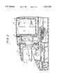
The adjustable circuit comprises resistance, and movement of the at least one contact adjusts the value of the resistance. The resistance is coupled in series with the contact means and is the resistive value referred to above connected in series with the valve element and the battery.
A method according to the invention for charging a battery, particularly but not exclusively an alkaline battery, comprises supplying a substantially constant current to the battery and providing a variable reference voltage including providing a first reference voltage which is greater than the voltage of the battery under charge, thereafter increasing the reference voltage up to a predetermined maximum voltage when the battery voltage rises above the reference voltage within a predetermined charging time period, and terminating the supply of current to the battery when the battery voltage does not rise above the reference voltage within the predetermined charging time period or when the reference voltage reaches the predetermined maximum voltage.
As indicated above, the reference voltage is preferably increased by discrete amounts up to the predetermined maximum reference voltage each time that the battery voltage rises above the reference voltage within the predetermined charging time period. The method may also include increasing from time to time the charging current being supplied to the battery by from about 2.5% to about 25% for up to a predetermined testing time period and maintaining the increased charging current substantially constant during the predetermined testing time period, and terminating the supply of current to the battery when the battery voltage increases by a predetermined amount within the predetermined testing time period while the increased, substantially constant charging current is being supplied to the battery.
The above and other objects, advantages, aspects and features of the invention will be more readily perceived from the following description of the preferred embodiments taken with the accompanying drawings and claims.
BRIEF DESCRIPTION OF THE DRAWINGS
The invention is illustrated by way of example and not limitation in the figures of the accompanying drawings in which like references denote like or corresponding parts, and in which:
FIG. 1 is a perspective view of a battery charger incorporating the invention which includes a plurality of battery holders for holding a plurality of same or different size batteries to be charged, the battery charger being depicted holding one battery to be charged;
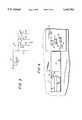
FIG. 2 a section view of a portion of the battery charger of FIG. 1 taken alongline 2--2 of FIG. 1;
FIG. 3 is a schematic diagram showing the battery size determining arrangement according to the invention which automatically connects selected resistance into a constant current circuit corresponding to the size of the battery connected to the battery holder for that constant current circuit;
FIG. 4 is a top view of a portion of the battery charger of FIG. 1 showing the switch contacts of the battery sizing arrangement for one of the battery holders which are activated by a lower slide member of that battery holder;
FIG. 5 is a block and schematic diagram of one embodiment of control and constant current circuitry according to the invention for the battery charger of FIG. 1;
FIG. 6 is a schematic diagram of one control circuit and one constant current circuit of the embodiment depicted in FIG. 5;
FIG. 7 is a schematic diagram of a computer implemented embodiment of a control circuit and a number of constant current circuits for the battery charger of FIG. 1; and
FIGS. 8A and 8B are a flow chart illustrating operation of the battery charger depicted in FIG. 7.
DESCRIPTION OF THE PREFERRED EMBODIMENTS
Thebattery charger 10 depicted in FIG. 1 may receive and charge up to four batteries, only one of which 12 is shown in broken lines.Battery charger 10 includes fouridentical battery holders 15, 16, 17 and 18, onepair 15, 16 of which being located at one side ofbattery charger 10 and anotherpair 17, 18 being located at the opposite side. Between the oppositely located pairs ofbattery holders 15, 16 and 17, 18 is a battery storage compartment 20 (FIG. 2) for holding up to eightbatteries 12, most of which will typically have been recharged so that recharged batteries will usually be available. A removable cover 21 closes the top ofbattery storage compartment 20. Located next to each pair ofbattery holders 15, 16 and 17, 18 aredisplay panels 25, 16 holding light emitting diodes(LEDs) 30-41 for battery holders 15-18. Three LEDs are provided for each holder 15-18. Eachdisplay panel 25, 26 includes a transparent plastic strip 29, 28 which covers LEDs 30-35 and LEDs 36-41, respectively. LEDs 30-32 are shown schematically in FIG. 6 for one control circuit and LEDs 30-41 are shown schematically in FIG. 7 for the computer-implemented control circuit of FIG. 7.
Battery holders 15-18 are identical. Therefore, the following description ofbattery holder 15 applies to battery holders 16-18.
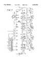
Referring to FIGS. 1 and 2, an upper spring-basedbattery engaging member 47, has mounted to its underside an upper contact 48 (FIG. 2) for electrically contacting the positive terminal of thebattery 12 placed inbattery holder 15.Contact 48 is about the same size and approximately in the same location as adepression 49 on the upper side of each upperbattery engaging member 40. A lower contact 50 (shown forbattery holder 16 in FIG. 1) is located belowcontact 48 to electrically contact the negative end ofbattery 12. Lower contact 50 (FIG. 1) is slightly recessed relative to alower body portion 43 of battery holder which is curved thereat to form acurved lip 44. Slidably mounted abovelower contact 48 is aslide member 51 having a V-shapedrecess 52 on the outer side thereof facingcurved lip 44.Lower contact 50 extends inwardly a substantial distance (FIG. 2) and has a substantial width to ensure electrical contact with the negative end of abattery 12 placed inbattery holder 15.Contacts 48 and 50 are sized and positioned to ensure electrical contact with any of battery sizes N, AAA, AA, C and D, and are electrically connected inbattery charger 10 as shown in FIGS. 5-7. A battery is seated onlower contact 50 engaged between v-shapedrecess 52 andcurved lip 44, as described below:
Referring to FIG. 2, upper battery holding member 45 is slidably mounted and is urged downwardly by a spring 53 to the lowermost position shown in FIG. 1 forbattery holder 16 such that the height ofupper contact 48 abovelower contact 50 is less than the height of the shortest battery (an N size battery).Slide member 51 abovelower contact 50 is also slidably mounted and is urged outwardly by a spring 54 to the outermost position shown in FIG. 1 forbattery holder 16. Referring to FIG. 1, to insert a battery into a battery holder 15-18, the battery positive terminal is placed underupper member 47, and the battery is pushed inwardly against V-shapedrecess 52 and upwardly againstupper member 47 to seat the battery on the respectivelower contact 50 between the v-shapedrecess 52 andcurved lip 44 in the respective battery holder 15-18. The force of springs 53 and 54 cause the battery to be engaged in thelower contact 50 between v-shapedrecess 50 andcurved lip 44.
Referring to FIGS. 2 and 3, a battery size detecting or determining arrangement referenced generally by 46 comprises switch 55 activated by movement of upperbattery engaging member 47 and switches 56, 57 and 58 activated by movement ofslide member 51. FIG. 2 shows switch 55 positioned to be activated to close by upward movement of upperbattery engaging member 47 and switches 56-58 positioned to be activated by movement ofslide member 51. As shown in FIG. 3, switches 56-58 are located side-by-side offset in the direction of movement ofslide member 51. Each switch 56-58 includes a movable contact 60-62 and a fixed contact 63-65 mounted on aPC board 70 to which other components of thebattery charger 10 are also mounted. Asslide member 51 moves inwardly, it activates switches 56, 57 and 58 sequentially depending on the distance moved. Thus, switch 56 alone may be activated, or bothswitches 56 and 57 may be activated or all threeswitches 56, 57 and 58 may be activated. FIG. 2 shows switches 56-58 activated (closed) for a D size battery held bybattery holder 15. Switch 55 (FIGS. 2 and 3) which is activated by upperbattery engaging member 47 includes amovable contact 70 and a fixed contact 71 which are wire-connected (not shown) toPC board 70. Switch 55 is in the open position when no battery or an N battery is held in a battery holder 15-18, as depicted in FIG. 2. Switch 55 remains open when an N size battery is seated in a battery holder, which requires little upward movement of upperbattery engaging member 47 that is insufficient to close switch 55. However, to seat an AAA, AA, C or D size battery, upperbattery engaging member 40 must be moved a distance sufficient to closecontacts 70 and 71 of switch 55.
In thebattery sizing arrangement 47, as shown in FIG. 3, switch 55 switches resistor R1, switch 56 switches resistor R3, switch 57 switches resistor R4 and switch 58 switches resistor R5. Switches 55-58 thus switch resistors in or out of thebattery sizing arrangement 46 provides a resistance value in series with transistor 116 (FIG. 5.) as shown in Table I, where the notation R1 //R2 means the resistance value of R1 in parallel with the resistance value of R2, etc.
              TABLE I                                                     ______________________________________                                    BATTERY                                                                   SIZE     SWITCH CONDITIONS RESISTANCE                                     ______________________________________                                    N        55 open; 56-58 open                                                                         R.sub.1 & R.sub.2                              AAA      55 closed; 56-58 open                                                                       R.sub.2                                        AA       55-56 closed; 57-58 open                                                                    R.sub.2 //R.sub.3                              C        56-57 closed; 58 open                                                                       (R.sub.2 //R.sub.3)//R.sub.4                   D        55-58 closed      (R.sub.2 //R.sub.3)//R.sub.4 ]//R.sub.5        ______________________________________
As shown in FIG. 5,battery charger 10 comprises atransformer 102, a fullwave bridge rectifier 103, avoltage regulator 104 and filtercapacitors 105 which provide a regulated DC voltage of about volts, and four identicalbattery charging circuits 110. In the embodiment shown in FIG. 5, eachbattery charging circuit 110 includes a separate control circuit ("the controlling means") 112 and a separate constant current circuit 114 ("the controlled means") for each battery holder 15-18). Constantcurrent circuit 114 includes atransistor 116 coupled in series with arespective battery 12 seated in a respective battery holder. FIG. 5 shows batteries connected inholders 15, 16 and 18. Eachcontrol circuit 110 is coupled to three LED indicators 30-32, 33-35, 36-39 and 40-42 (see FIGS. 1, 6 and 7), which are controlled byrespective control circuits 112. Coupled in each constantcurrent circuit 114 is a batterysize determinating arrangement 46 described above which switches a predetermined amount ofresistance 118 in series withtransistor 116 corresponding to the size of the battery held by the respective battery holder.
As depicted in FIG. 5, eachbattery charging circuit 110 includes aseparate control circuit 112 and a separate constantcurrent circuit 114 so that charging, testing and monitoring of eachbattery 12 is completely independent of charging, testing and monitoring of any other battery. The battery charging circuits 110 (including thecontrol circuits 112, the constantcurrent circuits 114 and the battery size determining arrangement 46) are identical. Therefore, the following description for one of thebattery charging circuits 110 shown in FIGS. 5 and 6 applies to the others.
Referring to FIG. 5, a constantcurrent circuit 114 includestransistor 116, resistance referenced generally by 118, transistor bias resistance referenced generally by 120 andcontrol inputs 122 and 123 which are coupled to controlcircuit 112.Control circuit 112 supplies oncontrol inputs 122 and 123 either a low signal (approximately ground) to sink any current on therespective control inputs 122 and 123, or a high signal (an approximate open circuit, e.g., an open collector or drain) onrespective control inputs 122 and 123. Resistors R7, R8 and R9 ofbias resistance 120 are selected to provide the nominal charging and test currents in Table II below for atransistor 116 such as, for example, an MV 5774C or an 8550, or equivalent, and aseries resistance 118 value given in Table II when operating from a DC supply voltage of +5 volts. Charging current is provided whencontrol input 122 is low (i.e., on) andcontrol input 123 is open (i.e., off); test current is provided whencontrol input 123 is low andcontrol input 122 open or low; and no current is provided whencontrol inputs 122 and 123 are both open. Both a charging current and a test current function to charge a battery, as described below. However, the test current is also used to determine the state of charge of a battery, as described below.
The nominal values of resistors R7, R8 and R9 are 820 ohms, 1.5K ohms and 560 ohms, respectively. However, the values may vary depending upon the transistor used and the charging and test current values desired.
Voltage regulator 104 supplies sufficient current at +5 volts output to charge and test four N, AAA, AA, C or D size 1.5 volt alkaline or nickel cadmium batteries (1.25 v) in any combination of sizes in accordance with the invention, and to supply current to power the various circuits inbattery charger 10 and light the various LEDs inbattery charger 10. Total maximum current draw is in the order of 0.5 amperes. The preferred nominal charging current for each size battery (either alkaline or nickel cadmium), the preferred nominal test current, and theseries resistance value 118 which produces the nominal currents are given in Table II for a typical transistor 116 (such as MV5774C or 8550) biased as shown in FIG. 6.
              TABLE II                                                    ______________________________________                                                                     Series                                                                    Resist.                                                                   118 In                                              Preferred             Ohms                                                Nominal    Preferred  For                                                 Charging   Nominal Test                                                                         Nominal                                  Battery Size                                                                         Current    Current    Current                                  ______________________________________                                    N           8.4 ma    12.2ma    87                                       AAA        9.73 ma    14.2 ma    75                                       AA         14.6 ma    21.4 ma    50                                       C          47.8ma      70 ma    15.27                                    D          63.4 ma    93.8 ma    11.53                                    ______________________________________
The preferred nominal charging current is about 1 ma per gram for N, AAA and AA sizes, about 0.73 ma per gram for C size and about 0.36 to about 0.49 ma per gram for D size. However, the charging current for the different sizes may vary over a range of values and still effectively charge alkaline and nickel cadmium batteries in accordance with the invention. This range is from about 80% of the preferred nominal valve to about 150% of the preferred nominal value, i.e., from about 0.28 ma per gram to about 1.5 ma per gram. The values for the test current, which is boosted or increased over the charging current, is from about 1.025 to 1.25 times the charging current for the respective battery size, i.e., an increase of from about 2.5% to about 25% over the particular charging current. The preferred range for the testing current is 1.025 to 1.10 times the particular charging current, i.e., a 2.5%-10% increase, and a nominal increase of 5% is preferred.
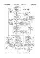
Whencontrol circuit 112 determines that charging current should be supplied to aparticular battery 12,control circuit 112 outputs a low to control or driveinput 122 and an open to controlinput 123 to supply a control signal to the control input (base) oftransistor 116 which turnstransistor 116 on so as to supply the nominal charging current given in Table II. Whencontrol circuit 112 determines that test current should be supplied to the particular battery,control circuit 112 outputs a low to controlinput 123 and either an open or a low to controlinput 122, which supplies a control signal to the base oftransistor 116 which turnstransistor 116 on harder so as to supply a current increased nominally by about 5% compared to the nominal charging current given in Table II. Whencontrol circuit 112 determines that no current should be supplied to theparticular battery 12,control circuit 112 outputs opens to bothcontrol inputs 122 and 123 to supply a control signal to the base oftransistor 116 which turns it off.
Each constantcurrent circuit 114 may optionally include an LED 130 (shown in broken lines in FIGS. 6 and 7) in series with the collector/emitter oftransistor 116 which is lighted whenever theparticular battery 12 is receiving charging or test current.
Constantcurrent circuit 114 supplies constant current to abattery 12 being charged as follows. With a low input to either or controlinput 122 or 123 bycontrol circuit 112,transistor 116 is turned on and supplies current to abattery 12. The +5 volt output ofregulator 104 is divided amongresistance 118, the collector-emitter circuit oftransistor 116, andbattery 12. As the voltage across battery 12 (battery voltage) changes, the voltage across the emitter-collector oftransistor 116 changes in the opposite direction so as to maintain the voltage acrossresistance 118 constant, thereby maintaining the current throughresistance 118 constant which is supplied tobattery 12 throughtransistor 116. Inclusion of anLED 130 betweentransistor 116 andbattery 12 does not affect constant current operation since the voltage acrossLED 130 will remain constant because the current passed throughLED 130 remains constant.
Referring to FIGS. 5 and 6,control circuit 112 includes timing means for measuring time, and receives a signal corresponding to the battery voltage oninput 140 through resistor 142 (FIG. 6), and in response to the signal oncontrol input 140 and the timing means, causes opens and lows to be output to controlinputs 122 and 123 to provide charging, test or no current to the respective batteries, and to light LEDs 30-32 as described below.
FIG. 6 depicts a logic implemented embodiment of onecontrol circuit 112 forbattery holder 15 according to the invention. The other threebattery control circuits 112 inbattery charger 10 for battery holders 16-18 are identical to controlcircuit 112. Therefore, the description below ofcontrol circuit 112 applies to the other three control circuits. In the embodiment depicted in FIGS. 5 and 6, eachcontrol circuit 112 controls the supply of current to thebattery 12 in the battery holder for that control circuit completely independently of the other control circuits, monitors thebattery 12 in the battery holder for that control circuit completely independently of the monitoring of any other batteries in the other battery holders, and controls lighting of the LEDS 30-32 completely independently of the lighting of LEDs 33-41.
FIG. 7 shows a computer-implemented version 10A ofbattery charger 10. In that embodiment, asingle control circuit 112A is provided in the form of amicrocontroller 250 which includes internal read only memory (ROM) and read/write or random access memory (RAM), four constantcurrent circuits 114 supplied with current fromregulator 104 and controlled bymicrocontroller 250, and anLED array 252 composed of LEDs 30-41 controlled bymicrocontroller 250.
Referring to FIG. 6,control circuit 112 forbattery holder 15 comprises a 0.5Hz clock 162, areference voltage counter 164 for incrementing the reference voltage, a digital to analog (DAC)converter 165 for converting the digital count signal (Q2-Q9) inreference voltage counter 164 to an analog reference voltage (DACOUT), acomparator 166 for comparing the battery voltage (BATT) to the analog reference voltage (DACOUT), acomparator 167 for comparing the battery voltage (BATT) to a fixed reference voltage (VCOMP) for determining when a battery has been inserted intobattery holder 15, atiming counter 170 for measuring predetermined times from clock pulses (TCLK) gated by ANDgate 171 fromclock 162,transistors 172 and 173 for controllingtransistor 116 of constantcurrent circuit 114,transistors 175, 176 and 177 for drivingLEDs 30, 31 and 32 respectively, and various logic circuits whose functions are described below.
As long as the AC power plug (not shown) forbattery charger 10 is plugged into the AC line, AC power is supplied to transformer 102 (FIG. 5), andregulator 104 outputs regulated +5 volts DC. With +5 volts being output byregulator 104 and no battery inbattery holder 15, RESET (FIG. 6) is generated at the output ofcomparator 167 when BATT (the battery voltage) oninput 140 from constantcurrent circuit 114 is higher than the 2.5 V fixed reference voltage VCOMP which are input to and compared bycomparator 167. The RESET signal (high) resets or causes to be reset the counters and flip-flops incontrol circuit 112. RESET (high) is generated each time abattery 12 is removed frombattery holder 15, and is maintained until a battery is re-inserted intobattery holder 15. When a battery is inserted intobattery holder 15, RESET goes low andcontrol circuit 112 is reset to start without any prior charging history. Besides resettingcontrol circuit 112 to commence charging a different battery, RESET may be used to re-check the status of a battery. For example, ifbattery charger 10 indicates that abattery 12 is charged (or not rechargeable), it may be removed to generate a RESET (high) and then replaced, andbattery charger 10 will determine anew the status of the battery and commence charging if the new status so indicates.
RESET is generated as follows. With no battery in thebattery holder 15, BATT is greater than the 2.5 V VCOMP reference voltage, and the VMAX, TMAX, and BSTOP signals supplied as inputs to NORgate 180 are all low, which drives the output of NOR gate 180 (CHGING) high, to turn ontransistor 172. Current flowing throughtransistor 172 causes the voltage at the base oftransistor 116 to drop, which causes base current to flow intransistor 116 to turntransistor 116 on and commence the supply of charging current tobattery 12. As a result, with no battery inbattery holder 15, the BATT signal supplied tocomparator 167 increases to approximately 5 volts, which drives the RESET output ofcomparator 167 high.
RESET fromcomparator 167 is supplied toreference voltage counter 164 which keeps all ofcounter 164 outputs low, and thereby the reference voltage output DACOUT ofDAC 165 is effectively at zero. The outputs oftiming counter 170 are set low with the first TCLK clock pulse from ANDgate 171 after RESET goes low as follows. A TCLK pulse is gated through AND gate 182 (as an UP pulse) toreference voltage counter 164. This causes a VSTEP pulse to be generated at the Q1 output ofreference voltage counter 164 which is supplied to the reset input oftiming counter 170. The DACOUT signal fromDAC 165 is compared incomparator 166 with the BATT signal. Since DACOUT is low (effectively zero) and BATT is high (greater than 2.5 V), the signal at the output of comparator 166 (BATT>DAC) is high, which enables ANDgate 182 to pass TCLK clock pulses to referencevoltage counter 164 However,reference voltage counter 164 is prevented from counting by the high RESET. A high RESET signal also holds flip-flop 185 reset and the Q output (BTIME) thereof low, and holds flip-flop 186 reset and the Q output thereof (BSTOP) low. A low BSTOP with a low VMAX and a low TMAX input to NORgate 180 causes the CHGING output of NORgate 180 to go high and turn ontransistor 172, as discussed above. A high RESET signal thereby effectively prevents timing functions and incrementing of thereference voltage counter 164 which are required during charging operation ofcontrol circuit 112.
When an N, AAA, AA, C orD battery 12 is electrically connected betweencontacts 48 and 50 ofbattery holder 15, BATT is no longer higher than VCOMP andcomparator 167 causes RESET to go low. Theseries resistance 118 in constantcurrent circuit 114 is set to the proper value for theparticular battery 12 by the battery size determining arrangement 46 (FIG. 3) which switches various resistors in parallel according to the physical size of the battery. When RESET goes low, the Q1 -Q9 outputs ofreference voltage counter 164 are initially low as a result of the high RESET signal.DAC 165 is set up for 2.55 v full scale output, but will be low initially due to all of the Q1 -Q9 outputs ofreference voltage counter 164 being low, so that DACOUT is less than BATT, and the output (BATT>DAC) ofcomparator 166 is high. CHGING remains high and allows ANDgate 171 to pass TCLK pulses to ANDgate 182. Sincecomparator 166 has a high output BATT>DAC, it enables ANDgate 182 to pass clock pulses (as UP pulses) to the clock input ofreference voltage counter 164, to cause it to count up. VSTEP pulses output from the Q1 output ofreference voltage counter 164 are supplied to the reset input oftiming counter 170 to reset it, as indicated above. The VSTEP signal output from Q1 ofreference voltage counter 164 alternates between high and low at one-half the rate of the TCLK pulses untilreference voltage counter 164 has counted up to the point when DACOUT exceeds BATT, which takes approximately 15 minutes from the time a battery is placed into thebattery holder 15, assuming a battery voltage of about 1.3 volts, the 0.5 Hzclock 162 and DACOUT is incremented in 0.01 volt steps at 0.01 volt per 8 seconds, as follows.
DAC 165 is set for 2.55 volts full scale for a 255 digital count ofreference voltage counter 164 outputs Q2 -Q9. SinceDAC 165 is incremented every 8 seconds, it would take about 34 minutes forDAC 165 to provide a full scale 2.55 volt output. (However,DAC 165 is only permitted to reach 1.63 volts, as discussed below.) Thus, when BATT exceeds DACOUT,comparator 166 outputs a high BATT>DAC signal which enables ANDgate 182 to clock UP pulses to referencevoltage counter 164, which then causes DACOUT to increase in 0.01 volt increments as long as CHGING is high and BATT>DAC. During this time period, the reference voltage is simply incremented to the point where it exceeds the battery voltage, at which time the charging cycle begins. During this time after RESET goes low, charging current is being supplied tobattery 10.
Whilereference voltage counter 164 is being incremented by UP clock pulses from ANDgate 182,timing counter 170 is being incremented by TCLK clock pulses from ANDgate 171, which occur every two seconds as long as charging current (CHGING high) is supplied tobattery 12. The Q5 output oftiming counter 170 goes high once approximately every 33 seconds as long as VSTEP pulses from the Q1 output ofreference voltage counter 164 are farther apart than 33 seconds so as not to firstreset timing counter 170. Similarly, the Q6, Q7, Q8 and Q9 outputs oftiming counter 170 go high at 66 seconds, 132 seconds, 264 seconds and 528 seconds as long as VSTEP pulses are that far apart. Outputs Q5 -Q12 oftiming counter 170 are coupled as inputs to NORgate 190. Whenever an output Q5 -Q12 oftiming counter 170 goes high, the output CTLOW of NORgate 190 goes low.
Whenever TSETUP (Q9 output of timing counter 170) goes high (approximately 9.5 minutes from the last VSTEP), it latches flip-flop 185 to set the Q output (BTIME) high. When TSETUP goes high, the output CTLOW of NORgate 190 goes low, then on the next increment ofreference voltage counter 164, output Q1 will have caused VSTEP to go high, resettlingtiming counter 170 and causing CTLOW to go high and remain high until the Q5 output oftiming counter 170 goes high (up to about 33 seconds following a VSTEP pulse). With CTLOW high, BTEST high and CHGING high, all supplied as inputs to ANDgate 192, the output BTEST of ANDgate 180 goes high to turntransistor 173 on (BTEST). This turnstransistor 116 on harder to pass about 5% more current (referred to herein as the test current) tobattery 12 and commence a current test, which is maintained until either the Q5 output oftiming counter 170 goes high (about 33 seconds) or the battery voltage (BATT) rises by 0.01 volt. When Q5 oftiming counter 170 goes high, it drives CTLOW low (output of NOR gate 202), which drives BTEST (output of AND gate 192) low, to turntransistor 123 off and returntransistor 116 to the normal charging condition. If, however, BATT exceeds DACOUT (inputs to comparator 166) before Q5 oftiming counter 170 goes high,comparator 166 outputs a high BATT>DAC which enables ANDgate 182 and allows a clock pulse UP to incrementreference voltage counter 164. This causes the Q1 output (VSTEP) ofreference voltage counter 164 to go high to set flip-flop 186 and cause the Q output (BSTOP) thereof to go high, which is supplied to NORgate 180 and causes the output (CHGING) thereof to go low. This means that the battery voltage has increased by more than a predetermined amount during the predetermined testing time period. A low CHGING signal turnstransistor 172 off, which causescontrol input 122 to go high andturn transistor 116 off and terminate the supply of current tobattery 12. When BSTOP goes high, it turnstransistor 177 on to lightred diode 32. As long as BSTOP is high,transistor 116 is off, no charging current is supplied tobattery 12 while it remains in the battery holder. This is an end of charge condition indicating that sufficient current has been supplied to the battery for a long enough time to prepare the battery for reuse.
The Q1, Q3, Q7 and Q9 outputs ofreference voltage counter 164 are provided as inputs to ANDgate 194. When Q1, Q3, Q7 and Q9 ofreference voltage counter 164 go high at a count of 1.63, the output (VMAX) of ANDgate 194 goes high. This drives the output of NORgate 180 low, to turn offtransistors 172 and 116 and terminate the supply of charging current tobattery 12. A count of 1.63 at the output ofreference voltage counter 164 corresponds to a reference voltage of 1.63 volts at the output (DACOUT) ofDAC 166. A high VMAX also turnstransistor 175 on to lightyellow LED 30, which indicates that charging has stopped due to reaching an upper voltage limit.
If VMAX goes high before BTIME (Q output of flip-flop 185) is latched, the NOT BTIME (Q NOT output of flip-flop 185) and VMAX signals to ANDgate 196 drive the DSET output of ANDgate 196 high to set flip-flop 186, which also causes thered LED 32 to be lighted together with theyellow LED 30. This indicates that the 1.63 volt level was crossed at a slope of greater than 0.01 volt in 91/2 minutes. Normally the battery voltage slope will drop off well before reaching 1.63 volts. A high slope indicates abattery 12 that is literally "dried up", or possibly a very fresh battery that was attempted to be charged twice in quick succession.
The normal stopping point for charging a battery in its long "middle age" is then continued, i.e., charging current is supplied to battery 12 (CHGING andtransistor 172 on). Charging is terminated if one of the conditions described above occurs, or if the battery voltage does not increase much in a long period of time. Charging will be terminated if the VSTEP pulses (Q1 output of reference voltage counter 164) exceed 1hour 10 minutes spacing, which causes the Q12 output (TIMEOUT) oftiming counter 170 to go high. The TIMEOUT output (Q12) oftiming counter 170 and the BTIME output of flip-flop 185 are supplied as inputs to ANDgate 198.
When both TIMEOUT and BTEST are high, the output TMAX of AND gate 214 goes high, which turns ontransistor 176 and lightsgreen LED 31. This indicates that charging has stopped because a long application of charging current has not resulted in a battery voltage increase (which includes the possibility that the voltage may actually have decreased somewhat.
Control circuit 112 upon insertion of a battery in holder 115 supplies current tobattery 12 while waiting for the reference voltage to be incremented to exceed the initial battery voltage, at which time a charging cycle begins. Whenever the battery voltage increases to exceed the reference voltage, a BTEST is conducted provided that the BTIME output of flip-flop 185 has been set high.Control circuit 112 terminates charging when specified conditions in terms of battery voltages, time and reference voltages are satisfied, as discussed above, for example when a maximum voltage is reached, or when the battery voltage increases by a predetermined amount during the predetermined testing (BTEST) time period, or if during normal charging, the battery voltage does not increase by a predetermined amount within a predetermined charging test period.
Referring now to FIG. 7, a computer implemented embodiment ofbattery control circuit 112A for a battery charger 10A is shown.Control circuit 112A controls four constantcurrent circuits 114 which may be identical to or substantially the same as constantcurrent charging circuits 114 ofbattery charging circuit 110.Control circuit 112A is embodied by amicrocontroller 250. Likebattery charger 10, battery charger 10A includes four separate constantcurrent circuits 114, so that charging and testing of eachbattery 12 in a holder 15-18 is essentially independent of the charging and testing of anyother battery 12 held in any other battery holder 15-18. However, because each constantcurrent circuit 114 shares acommon control circuit 112A, monitoring thebatteries 12 held by the battery holders is done on a sequential or time shared basis, while control of the constantcurrent circuits 114 is done on a parallel output basis whereby chargers and test currents may be maintained continuously or individual circuits may be turned on or off on command. Sincemicrocontroller 250 operates at a much higher speed than the basic 0.5 Hz rate at whichbattery charger 10 operates, battery charger 10A operates with essentially the same performance (or better due to higher operating speed) asbattery charger 10.
Constantcurrent circuits 114 in battery charger 10A operate from the +5 volt output of regulator 104 (FIG. 5) the same as described for constantcurrent circuits 114 inbattery charger 10.Microcontroller 250 outputs control signals oncontrol inputs 122 and 123 and receives the BATT signal oninput 140, as do thecontrol circuits 112 ofbattery charger 10.Microcontroller 250 controls LEDs 30-41 by means of output control signals PA4, 5 and 6 comparable to CHGING (yellow LED), BSTOP, TMAX or VMAX (green LED) and BSTOP (red LED) output bycontrol circuits 112 for one set of LEDs, but uses the same threePA 4, 5 and 6 control lines and four sink lines PA0-PA3 ofmicrocontroller 250 as address lines to address each set 30-32, 33-35, 36-38 and 39-41 of LEDs. The LEDs are refreshed often enough to avoid flicker.
Microcontroller 250 includes internal circuitry for a clock (not shown) whose frequency is set bycrystal 254, an internal analog to digital convertor (ADC), a CPU, internal registers, and internal ROM and RAM.Microcontroller 250 may be SGS-Thomson Microelectronics model ST6215. Other suitable microcontrollers, microcomputers, microprocessors plus any needed external components such as an ADC, ROM, etc., may be used.
For the SGS-Thomson microcontroller, which is illustrated in FIG. 7, PA0-PA3 are sink inputs of port A; PA4-PA7 are programmable analog input/outputs (I/O) functioning as analog outputs of port A; PBO-PB7 are programmable analog I/Os functioning as inputs of port B and PC4-PC7 are programmable analog I/Os functioning as inputs of port C. Incontrol circuit 112 of FIG. 6,DAC 165 has a maximum input count of 2561175. In order to reach 2.56 volts, a step increment of 0.01 volt was selected. However other step increments may have been used, as indicated above. The voltage step size of the internal ADC ofmicrocontroller 250 is given by the maximum magnitude of the reference voltage supplied to microcontroller 250 (from 2.56 to 5.0 volts) divided by 256 steps. This means that the size of the step may be selected from 0.01 volt to 0.195 volts.
Microcontroller 250 operates to control constantcurrent circuits 114 and to monitorbatteries 12 held by battery charger 10A as illustrated by the flow chart depicted in FIGS. 8A and 8B.
Referring to FIG. 8A, upon applying power tomicrocontroller 250, aninitialization step 300 is carried out, after which instep 302 the X index is incremented to causemicrocontroller 250 to prepare to monitor the constantcurrent circuit 114 for the battery held in the first battery holder 15 (or in the next battery holder 15-18 depending on the X index if the incrementingstep 302 is performed from the X1 loop). The flow chart of FIGS. 8A and 8B illustration operation of a battery charger 10A which has four battery holders 15-18 for charging fourbatteries 12. An X index (0, 1, 2 and 3) causesmicrocontroller 250 to process the four constantcurrent circuits 114 for battery holders 15-18, respectively, while continuously and simultaneously supplying current to the constantcurrent circuits 114 when called for. Therefore, instep 304microcontroller 250 checks to see whethermicrocontroller 250 was last monitoring the "3" X index forbattery holder 18, and if so (index>3), resets the X index instep 306. Instep 308,microcontroller 250 reads the internal analog to digital converter (ADC) output for theparticular battery 12 being monitored. If instep 310 the ADC output (which corresponds to the analog BATT voltage in control circuit 112) is greater than a maximum reference voltage VD of 2.5 v (which corresponds to the fixed reference voltage VCOMP in battery charging circuit 110), then no battery is being held by the particular battery holder 15-18 being monitored, andmicrocontroller 250 resets all registers and FLAG bits instep 312, then reads the FLAGS in step 314 (all zero) and jumps to step 328. Table III below defines an 8-bit FLAG word.
                                  TABLE III                               __________________________________________________________________________BIT NO.   0   1    2    3   4   5   6     7                               __________________________________________________________________________FUNCTION  CHG BTEST                                                                          TMSET                                                                          ISTEP                                                                         ENDG                                                                          ENDR                                                                          IDELAY                                                                          (SPARE)                         __________________________________________________________________________
The CHG flag gives the status ofcontrol line 122 which when high (set) indicates that charging current is being supplied to a particular battery. The BTEST gives the status ofcontrol line 123 which when high (set) indicates that test current is being supplied to a particular battery. ISTEP controls the supply of current during a BTEST to a battery being charged. TMSET gives the status of a timing counter (CT) count for the maximum predetermined time allowed between predetermined increments of a battery under charge before charging will be terminated, and corresponds to BTIME in control circuit 112 (FIG. 6). ENDG gives the status when charging is complete and the battery is usable; it combines indications in each set of LEDs 30-32, 33-35, 36-38 and 39-41 ofbattery charger 10. ENDR gives the status when charging is terminated but the battery is of questionable use; it replaces the condition when the yellow and red LEDs (30 and 32 in FIG. 6) were turned on simultaneously. ENDR also indicates another condition not implemented inbattery charger 10, that is, it indicates a battery having too low initial terminal voltage which is probably not rechargeable, or if a battery is placed inverted into a holder. IDELAY gives the status of the count of the timing counter (CT) count for the settling time, which prevents determining and indicating the charge status of a battery for a short period of time while a user inserts and seats a battery.
If thestep 310, ADC does not exceed the fixed reference/voltage VD, which means that a battery is not in the battery holder, VD being, for example, 2.5 V similar to VCOMP in FIG. 6, thenmicrocontroller 250 instep 316 determines whether ADC is less than a minimum reference voltage VA of about 0.85 volt. If yes, meaning that the battery voltage is too low to be recharged, or if it was inserted inverted into the particular battery holder, all registers and flag bits are reset in step 318, andflag bit 5, ENDR, is set, which lights the red LED for the particular battery holder. Referring to FIG. 7, an LED is lighted bymicrocontroller 250 by driving the one of outputs PA4, PA5 or PA6 high, and the one of the address (sink) inputs PA0, PA1, PA2 or PA3 low to address the LED which is to be lighted. As mentioned, the LEDs are driven at a high enough refresh rate that they do not appear to flicker.
Referring again to FIG. 8A, after setting flag ENDR and the appropriate red LED instep 320,microcontroller 250 in step 324 reads FLAG bits 0(CHG), 4(ENDG) and 5(ENDR). IfFLAG bits 0, 4 and 5 are not set (off or low), as determined in step 324, thenmicrocontroller 250 sets FLAG bits 0(CHG) and 6(IDELAY) high. Instep 328, microcontroller 200 turns on the yellow, green or red LED, or no LED, corresponding to which, if any, ofFLAG bits 0, 4 and 5 is set from previous steps. Instep 330, the current to thebattery 12 in the particular battery holder 15-18 being monitored is set either to the charging current (CHG bit 0 set,control line 122 low), or to the test current (ISTEP bit 3 set,control line 123 low). Instep 332, a timing counter register (implemented in RAM) is incremented, which has a capacity of 500 counts for 2 seconds. If instep 334, the count in the timing counter is less than 2 seconds, then the program returns to step 302 which increments the X index andmicrocontroller 250 monitors thebattery 12 in the next battery holder 15-18. The time for one passage around the X loop is set to be about 4 ms by suitable time delays and interrupts utilized within the loop. The X1 loop is left temporarily whenever the count in the timing counter is greater than two seconds (step 334). The X1 loop sets up a two second set-up time in which all battery holders 15-18 are monitored, flags read and set, etc. If instep 334 the X index timer is greater than or equal two seconds, then instep 336 the X index timer is reset and the X index is set to 0.
Battery monitoring now continues in an X2 loop starting from battery holder 15 (X index 0). Instep 338 the ADC (battery voltage) is read, and instep 340,microcontroller 250 determines if ADC (current battery voltage) is greater than the fixed VD reference voltage of 2.5 volts. If yes, meaning that there is no battery in thebattery holder 15, the flags and registers are reset instep 342 and the X index is incremented tobattery holder 16 instep 334. Step 346 will determine whether the X index is less than 3, and if so cause the program to start in the X2 loop,step 302. If the X index is not less than 3, the ADC is read instep 338 and step 340 determines if the ADC is greater than the fixed reference voltage, VD (2.5 volts). If instep 340 ADC is not greater than VD, meaning that abattery 12 is inholder 15, then step 348 reads the FLAG bits. If in step 350 (FIG. 8B), FLAG bit 4(ENDG) or FLAG bit 5(ENDR) is set, meaning that charging has terminated for the battery in the particular holder with a red or green LED turned ON, then the program jumps back to step 344 (FIG. 8A). If however,FLAG bits 4 and 5 are off (step 350, FIG. 8A), which means that there is a battery inbattery holder 15 and it is under charge, then instep 352 the timing counter (CT) is incremented. In step 354 (FIG. 8B), if FLAG bit 6 (IDELAY) is set, meaning that a predetermined settling time of about 15 seconds since a battery was inserted into the particular battery holder has not elapsed, then instep 356 the count in the timing counter (CT) is compared to a fixed settling time TA of about 15 seconds, and if less than the minimum settling time TA has not elapsed, the program increments the X index and moves to the next X increment in the X2 loop at step 344 (FIG. 8A). If CT is greater than TA (step 356), which indicates that the settling time TA has elapsed, than FLAG 6 (IDELAY) is reset instep 358, the initial ADC battery voltage is saved as ADCO (last battery voltage) and VINIT (initial battery voltage) instep 360, the timing counter (CT) is reset instep 362 and the program increments X index in step 344 (FIG. 8A) and remains in the X2 loop.
If instep 354 FLAG bit 6 (IDELAY) was not set, meaning that the settling period had expired andFLAG bit 6 was reset per steps 356-362, then the timing counter (CT) count is compared to a maximum charging time period TD of about 4200 seconds (one hour, ten minutes). This maximum time period corresponds to timing counter 170 output Q12 (FIG. 6) incontrol circuit 112, and indicates that charging current has been supplied to the battery for the maximum TD time without the ADC (battery) voltage rising by a predetermined amount (0.01 volt). That means that the battery has been successfully charged. Then the FLAG bits are reset, FLAG bit 4 (ENDG) is set, indicating a charged battery, the green LED for that battery holder is lit, and charging current to the battery in the particular holder is terminated (FLAG bit 0 reset).
If instep 364 the count of the timing counter (CT) is not greater than the maximum time TD, then charging continues. If instep 368 FLAG bit 1 (BTEST) is set (on), the program branches to step 370. If instep 370 the current battery voltage (ADC) is greater than the previous saved battery voltage (ADCO) by the predetermined amount, the program branches to branch to step 372. If instep 372 CT is greater than TB of about 33 seconds, then instep 374, FLAG bits 1 (BTEST) and 3 (ISTEP) are reset (turned off). This causes outputs PB0, PB2, PB4, or PB6 to go open terminating the test current increase. The program proceeds to step 362 in which the timing counter (CT) count, which is stored in two bytes, THI for most significant bits and TLO for least significant bits, is reset to zero, and the X index increment in step 344 (FIG. 8A).
If instep 370 the current battery voltage (ADC) is not greater than the previous saved battery voltage (ADCO), the program branches to step 376. If instep 376 the timing count (CT) count is greater than the BTEST time delay period TB, then instep 374 FLAG bits 1 (BTEST) and 3 (ISTEP) are reset to zero to end the BTEST and turn off the test current by making PB0, 2,4 and 6 go to open, and CT is reset to zero instep 362.
If instep 376, CT is not greater than TB, indicating that it is not time for the BTEST to end, the program branches to step 380. If instep 380 the timing counter (CT) count is greater than the TSETUP time TC (corresponding to Q9 output oftiming counter 170 in FIG. 6) which is the time for monitoring whether the battery voltage changed by a predetermined step, then instep 381 FLAG bit 2 (TMSET) is set, and the program returns to the X2 loop. (step 344 in FIG. 8A).
If instep 368FLAG 1 bit (BTEST) was not set, and instep 378 the current battery voltage (ADC) was greater than the previous saved battery voltage ADCO, meaning that the battery voltage increased by the predetermined amount within a BTEST time period, then the program branches to step 382, where previous battery voltage (ADCO), which corresponds to the reference voltage DAC in chargingcircuit 110, and the current battery voltage are saved (incremented). If instep 384 the current battery voltage is greater than the maximum battery voltage VC (1.63 volts), the program branches to step 386. If instep 386 FLAG bit 2 (TMSET) is not set, meaning the TSETUP time has never been exceeded, then the program branches to step 388. If instep 388 the initial battery voltage (VINIT) was less than or equal to 1.35 volts (VE) (unsatisfactory condition), then instep 390 the FLAG bits are reset and FLAG bit 5 (ENDR) is set. However, if VE>1.35 v instep 386, then FLAG bit 4 (ENDG) is set in step 366 and the green LED is lighted to indicate a nearly new battery.
Instep 384, if the current battery voltage ADC is not greater that the maximum predetermined voltage VC (1.63 volts) and if instep 392FLAG bit 2 TMSET is set, then FLAGbits 1 and 3 are then the program branches to step 392, set meaning that a BTEST may be done at any increment of the ADCO once TIMESET is set on. TIMESET is not turned off untilstep 366 or 390 when charging ends, or it possibly could be turned off in the X1 loop by removing the battery. When the BTEST control signal is on, and most particularly ISTEP, this signal appears as a low on the appropriate PB0, PB2, P4 or PB6 line to cause test current to be supplied to the appropriate battery. Thereafter, and if instep 392 FLAG bit 2 (TMSET) was not set, the THI and THO times in timing counter (CT) are reset, and the X2 loop entered.
While the invention has been described and illustrated in connection with preferred embodiments, many variations and modifications as will be evident to those skilled in this art may be made without departing from the spirit and scope of the invention. The invention as set forth in the appended claims is thus not to be limited to the precise details of construction set for the above and such variations and modifications are intended to be included within the scope of the invention.

Claims (56)

What is claimed is:
1. A battery charger particularly but not exclusively for charging alkaline batteries, comprising:
controlled means for supplying substantially constant charging current from a power source to a battery under charge or terminating the supply of charging current to the battery;
controlling means for controlling said controlled means, said controlling means including means for providing an adjustable reference voltage, said controlling means causing said controlled means to:
supply said substantially constant charging current to the battery while causing said reference voltage means to provide said reference voltage which is greater than a battery voltage available at terminals of the battery, and to thereafter provide, as the battery voltage increases, increased reference voltages, up to a predetermined maximum reference voltage, which exceed the battery voltage and which exceed a previous reference voltage; and
terminate the supply of charging current to the battery upon the occurrence of a condition based upon a relationship of the reference voltage and the battery voltage, or a relationship of the reference voltage, the battery voltage and time.
2. The battery charger of claim 1 wherein said condition for terminating the supply of charging current to the battery is when the battery voltage does not increase during charging to be greater than a first or a subsequent reference voltage during a predetermined charging time period.
3. A battery charger particularly but not exclusively for charging alkaline batteries, comprising:
controlled means for supplying substantially constant charging current from a power source to a battery under charge or terminating the supply of current to the battery;
controlling means for controlling said controlled means, said controlling means including means for providing an adjustable reference voltage, said controlling means causing said controlled means to:
supply said substantially constant charging current to the battery while causing said reference voltage means to provide said reference voltage which is greater than a battery voltage available at terminals of the battery, and to thereafter provide, as the battery voltage increases, increased reference voltages, up to a predetermined maximum reference voltage, which exceed the battery voltage and which exceed a previous reference voltage; and
terminate the supply of charging current to the battery when said reference voltage means provides the predetermined maximum reference voltage, or when the battery voltage does not increase during charging to be greater than a first or a subsequent reference voltage during a predetermined charging time period.
4. A battery charger particularly but not exclusively for charging alkaline batteries, comprising:
controlled means for supplying a substantially constant but adjustable charging current from a power source to a battery under charge or terminating the supply of current to the battery;
controlling means for controlling said controlled means to cause said controlled means to supply said substantially constant charging current to the battery as a battery voltage available at terminals of the battery changes during charging of the battery, from time to time during a testing period cause said controlled means to supply a substantially constant test current to the battery which exceeds the charging current by from about 2.5% to about 25%, and to cause said controlled means to terminate the supply of current to the battery when said controlled means is providing said charging current to the battery and the battery voltage reaches a predetermined maximum voltage, or when said controlled means is supplying said test current to the battery and the battery voltage increases by greater than a predetermined amount within a respective testing period.
5. A battery charger particularly but not exclusively for charging alkaline batteries, comprising:
controlled means for supplying a substantially constant but adjustable charging current from a power source to a battery under charge or terminating the supply of current to the battery;
controlling means for controlling said controlled means, said controlling means including means for providing an adjustable reference voltage, said controlling means causing said controlled means to:
supply said substantially constant charging current to the battery while causing said reference voltage means to provide said reference voltage which is greater than a battery voltage available at terminals of the battery, and to thereafter provide, as the battery voltage increases, increased reference voltages, up to a predetermined maximum voltage, which exceed the battery voltage and which exceed a previous reference voltage within a predetermined charging time period after a first or a subsequent reference voltage is provided;
from time to time during a testing period supply a substantially constant test current to the battery which exceeds the charging current by from about 2.5% to about 25%; and
terminate the supply of current to the battery when said reference voltage means provides the predetermined maximum voltage, or when the battery voltage increases by greater than a predetermined amount during a respective testing period when test current is being supplied to the battery, or when the battery voltage does not increase during charging to be greater than a first or a subsequent reference voltage during any predetermined charging time period.
6. The battery charger according to claim 4 or 5 wherein said controlling means causes said controlled means to resume the supply of charging current to the battery after the testing period when said controlling means does not cause said controlled means to terminate the supply of current to the battery.
7. The battery charger of claim 3 or 5 wherein said controlling means causes said reference voltage means to increase the reference voltage in discrete increments.
8. The battery charger of claim 3 or 5 wherein said battery charger is configured to charge batteries rated at about 1.25 volts to about 1.5 volts, and wherein said controlling means causes said reference voltage means to increase the reference voltage by a fixed amount of from about 0.005 volt to about 0.05 volt.
9. The battery charger of claim 3 or 5 wherein said battery charger is configured to charge batteries rated at about 1.25 volts to about 1.5 volts, and wherein said controlling means causes said controlled means to supply said constant charging current of between about 0.28 ma and about 1.5 ma per gram weight of the battery, and wherein said controlling means causes said reference voltage means to increase the reference voltage by a fixed amount of about 0.01 volt.
10. The battery charger of claim 3, 4 or 5 wherein said battery charger is configured to charge batteries rated at about 1.25 volts to about 1.5 volts, and wherein said reference voltage means is configured to provide said predetermined maximum reference voltage of about 1.6 volts.
11. The battery charger of claim 3 or 5 wherein said battery charger is configured to charge batteries rated at about 1.25 volts to about 1.5 volts, and wherein said controlling means causes said controlled means to supply said constant charging current of between about 0.28 ma and about 1.5 ma per gram weight of the battery, and wherein said predetermined charging time period is from about 45 minutes to about 2 hours.
12. The battery charger of claim 4 or 5 wherein said battery charger is configured to charge batteries rated at about 1.25 volts to about 1.5 volts, and wherein said controlling means causes said controlled means to supply said constant charging current of between about 0.28 ma and about 1.5 ma per gram weight of the battery, and wherein said testing period is from about 10 seconds to about 60 seconds in duration.
13. The battery charger of claim 4 or 5 wherein said controlling means causes said controlled means to supply the testing current a predetermined time after an increase of the reference voltage.
14. The battery charger of claim 3, 4 or 5 wherein said controlled means comprises a valve element coupled to the power source and the battery such that when said controlled means is supplying said charging current, said charging current is maintained substantially constant by action of said valve element as the battery voltage changes.
15. The battery charger of claim 14 wherein said controlling means causes a control signal of a first value to be supplied to said valve element when causing said controlled means to provide said charging current, and causes a control signal of a second value to be supplied to said valve element when causing said controlled means to terminate the supply of current to the battery.
16. The battery charger of claim 15 wherein said controlled means comprises a resistive element coupled in series between the power source and the battery, said valve element and said resistive element being coupled such that when said controlled means is supplying said charging current to the battery the voltage across said resistive element is maintained substantially constant by action of said valve element as the battery voltage changes.
17. The battery charger of claim 16 wherein said valve element has a control input, an input and an output and passes current between said input and said output in dependence upon said first and second value control signals caused to be supplied to said control input by said controlling means, said input and said output being coupled in series with said resistive element between said power source and said battery.
18. The battery charger of claim 17 wherein said controlling means provides first and second control signals on first and second outputs thereof, and wherein said controlled means in response to said first and second control signals provides said first and second value control signals, respectively, to said control input of said valve element.
19. The battery charger of claim 18 wherein said valve element comprises a transistor device and said controlled means comprises a circuit coupling said first and second control signals on said first and second outputs of said controlling means to said control input of said transistor device.
20. The battery charger of claim 4 or 5 wherein said controlled means comprises a valve element coupled to the power source and the battery such that when said controlled means is supplying said charging current, said charging current is maintained substantially constant by action of said valve element as the battery voltage changes, and when said controlled means is supplying said test current, said test current is maintained substantially constant by action of said valve element as the battery voltage changes.
21. The battery charger of claim 20 wherein said controlling means causes a control signal of a first value to be supplied to said valve element when causing said controlled means to provide said charging current, causes a control signal of a second value to be provided to said valve element when causing said controlled means to supply said test current, and causes a control signal of a third value to be supplied to said valve element when said controlled means terminates the supply of current to the battery.
22. The battery charger of claim 20 wherein said controlled means comprises a resistive element coupled in series between the source of direct current and the battery, said valve element and said resistive element being coupled such that when said controlled means is supplying said charging current or said test current to the battery the voltage across said resistive element is maintained substantially constant by action of said valve element as the battery voltage changes.
23. The battery charger of claim 22 wherein said valve element has a control input, an input and an output and passes current between said input and said output in dependence upon said first, second and third value control signals caused to be supplied to said control input by said controlling means, said input and said output being coupled in series with said resistive element between said power source and said battery.
24. The battery charger of claim 23 wherein said controlling means provides first and second control signals on first and second outputs thereof, and wherein said controlled means in response to said first and second control signals provides said first and second value control signals, respectively, to said control input of said valve element, and in response to an absence of both of said first and second control signals provides said third value control signal to said control input.
25. The battery charger of claim 24 wherein said valve element comprises a transistor device and said controlled means comprises a circuit coupling said first and second control signals on said first and second outputs of said controlling means to said control input of said transistor device.
26. The battery charger of claim 16 wherein said controlled means is coupled to a power source having a substantially constant voltage which is greater than the battery voltage when the battery is substantially fully charged.
27. The battery charger of claim 22 wherein said controlled means is coupled to a source having a substantially constant voltage which is greater than the battery voltage when the battery is substantially fully charged.
28. A battery charger for charging at least one battery which may be any of a plurality of different sizes, particularly but not exclusively for charging alkaline batteries, comprising:
at least one circuit coupled to a power source;
a holder associated with each said circuit for holding therein a single battery of any of said sizes, each said holder including contacts for electrically connecting to a battery held therein, each said circuit supplying current to the battery held in the associated holder through the contacts thereof;
controlling means for monitoring a battery voltage available at terminals of each battery held in a respective holder, and in response thereto, controlling the charging of a respective battery in a respective holder, each said circuit being responsive to said controlling means to supply charging current to a respective battery and terminate supply of charging current to a respective battery;
each said holder including a movable element whose position is determined by the physical size of a battery held in the holder, each said movable element being coupled to a respective circuit so as to cause the respective circuit to automatically supply a predetermined charging current to a respective battery which is different for batteries of at least two different sizes in response to the position of the movable element.
29. The battery charger of claim 28 wherein said battery charger is constructed to charge a plurality of batteries of the same or different size at the same time, and includes a plurality of circuits, each with a single associated holder, said controlling means controlling charging of each battery held by a holder.
30. The battery charger of claim 28 wherein said contacts of each holder comprise a contact carried by the respective movable element.
31. The battery charger of claim 28 wherein said battery charger includes separate controlling means for each said circuit.
32. The battery charger of claim 28 wherein each said circuit comprises resistance coupled in a respective circuit such that the value thereof affects the value of the charging current supplied by a respective circuit to a battery held in the associated holder, the movable element of a respective holder being coupled to a respective circuit such that in at least two positions of a respective movable element the resistance of a respective circuit is different, whereby a respective circuit can supply charging current of at least two different values depending upon the position of the respective movable element which is determined by the physical size of the battery held in the respective holder.
33. The battery charger of claim 32 wherein said resistance is coupled in series with a respective circuit and at least one of the contacts.
34. The battery charger of claim 28 wherein each said circuit comprises a valve element coupled to a respective battery such that the charging current supplied by the respective circuit is maintained substantially constant at the value set by said circuit under control of said controlling means by action of said valve element as the battery voltage of the respective battery changes.
35. The battery charger of claim 32 wherein each said circuit comprises a valve element coupled to a respective battery such that the charging current supplied by the respective circuit is maintained substantially constant at the value set by said circuit under control of said controlling means by action of said valve element as the battery voltage of the respective battery changes and wherein each said resistance is coupled in series with a respective valve and at least one of the respective contacts.
36. A method for charging a battery, particularly but not exclusively an alkaline battery, comprising:
supplying a substantially constant current to the battery; and
providing a variable reference voltage including providing a reference voltage which is greater than a battery voltage available at terminals of the battery under charge, thereafter increasing the reference voltage up to a predetermined maximum voltage when the battery voltage rises above the reference voltage within a predetermined charging time period, and terminating the supply of current to the battery when the battery voltage does not rise above a first or a subsequent reference voltage within the predetermined charging time period or when the reference voltage reaches the predetermined maximum voltage.
37. The method of claim 36 wherein the reference voltage is increased by discrete amounts up to the predetermined maximum reference voltage each time that the battery voltage rises above the reference voltage within the predetermined charging time period.
38. A method for charging and determining the charge state of a battery, particularly but not exclusively an alkaline battery, comprising:
supplying a substantially constant charging current to the battery as a battery voltage available at terminals of the battery changes during charging of the battery, and monitoring the voltage of the battery;
from time to time increasing the charging current being supplied to the battery by from about 2.5% to about 25% for up to a predetermined testing time period, and maintaining the increased charging current substantially constant during the predetermined testing time period;
terminating the supply of current to the battery when the battery voltage increases by a predetermined amount within the predetermined testing time period while the increased, substantially constant charging current is being supplied to the battery.
39. The method of claim 38 including the step of terminating supply of current to the battery when the battery voltage reaches a predetermined voltage.
40. The method of claim 38 including the steps of providing a variable reference voltage including providing a reference voltage which is greater than the battery voltage, thereafter increasing the reference voltage up to a predetermined maximum voltage when the battery voltage rises above the reference voltage within a predetermined charging time period, and terminating the supply of current to the battery when the battery voltage does not rise above the reference voltage within the predetermined charging time period or when the reference voltage reaches the predetermined maximum reference voltage.
41. The method of claim 40 wherein the charging current is increased a predetermined time after an increase of the reference voltage.
42. The method of claim 40 wherein the reference voltage is increased by discrete amounts up to the maximum reference voltage each time that the battery voltage rises above the reference voltage within the predetermined charging time period.
43. A method for charging batteries of N, AAA, AA, C and D sizes, comprising:
supplying a substantially constant charging current of between about 0.28 ma and about 1.5 ma per gram weight of the battery to the battery being charged; and
providing a variable reference voltage including providing a reference voltage which is greater than a battery voltage available at terminals of the battery under charge, thereafter increasing the reference voltage, up to a maximum voltage of about 1.6 volts, when the battery voltage rises to exceed the reference voltage within a predetermined charging time period, and terminating the supply of current to the battery when the battery voltage does not rise above the reference voltage within the predetermined charging time period or the reference voltage reaches the maximum voltage.
44. The method of claim 43 wherein the reference voltage is increased by discrete amounts up to the maximum reference voltage each time that the battery voltage rises above the reference voltage within the predetermined charging time period.
45. The method of claim 44 including:
increasing the charging current being supplied to the battery from time to time during a testing period by from about 2.5% to about 25% and maintaining the increased charging current substantially constant during the testing period;
terminating the supply of current to the battery when the battery voltage increases by a predetermined amount within the testing period while the increased, substantially constant charging current is being supplied to the battery.
46. The method of claim 45 wherein the charging current is increased a predetermined time after an increase of the reference voltage.
47. A battery charger for charging batteries of different sizes, comprising:
means for supplying charging current from a power source;
contact means including at least one contact element through which charging current is supplied from said charging current supplying means to a battery;
means for holding a single battery in electrical connection with said contact means; and
an adjustable circuit which controls the magnitude of charging current supplied by said charging current supplying means to the battery held by said battery holding means, said contact element being movably mounted in said battery holding means to accommodate and electrically connect batteries of different sizes, and means mechanically coupling said contact element with said adjustable circuit such that said charging current supplying means supplies charging currents of values dependent upon the position of said contact element.
48. The battery charger of claim 47 wherein said adjustable circuit comprises resistance coupled to said charging current supplying means, and wherein the position of said contact element determines the value of said resistance.
49. The battery charger of claim 48 wherein said resistance is coupled in series with said contact element and said charging current supplying means.
50. A battery charger for charging a plurality of batteries of the same or different size, particularly but not exclusively alkaline batteries, comprising:
a contact means for each battery to be charged including a contact element through which charging current is supplied to a respective battery;
a means for each battery to be charged for holding a single battery to be charged in electrical connection with a respective contact means;
means for supplying substantially constant charging current from a power source to respective contact means of respective battery holding means essentially independently of the charging current supplied to any other contact means;
an adjustable circuit for each contact means which controls the magnitude of the charging current supplied by said current supplying means to the respective contact means;
said contact element of a respective contact means being movably mounted in a respective battery holding means to accommodate and electrically connect to the respective contact means batteries of different sizes; and
means mechanically coupling said contact element of a respective contact means with said adjustable circuit such that movement of a respective contact element adjusts a respective adjustable circuit and causes said current supplying means to supply charging currents to respective contact means of values dependent upon the position of a respective contact element.
51. The battery charger of claim 50 wherein each adjustable circuit comprises resistance coupled to said current supplying means, and wherein the position of a respective contact element determines the value of a respective resistanace.
52. The battery charger of claim 51 wherein a respective resistance is coupled in series with a respective contact element and said current supplying means.
53. A battery charger for charging a plurality of batteries of the same or different size, particularly but not exclusively alkaline batteries, comprising:
a plurality of circuits coupled to a source of power, each circuit including a holding means for holding therein a single battery of any size of a plurality of different sizes and for supplying charging current to said battery from the power source, contact means for electrically connecting a respective circuit to a battery held by a respective holding means, and resistance in series with said contact means such that charging current supplied to a respective battery flows through a respective resistance, each said resistance being selectable in magnitude;
each said circuit supplying charging current to the battery held by the respective battery holding means essentially independently of any other circuit such that two or more circuits may supply charging current to respective batteries continuously and simultaneously in response to said controlling means, and to terminate the supply of charging current to respective batteries in response to said controlling means; and
means associated with each of said circuits responsive to the size of a battery held by an associated holding means of a respective circuit for automatically selecting a magnitude of a respective resistance of a respective circuit, whereby the charging current supplied by a respective circuit to a respective battery in a respective holding means is selectable independently of charging current supplied by any other circuit to any other battery.
54. The battery charger of claim 53 including means for controlling the charging of each battery in a holding means, each said circuit being responsive to said controlling means to supply supply of charging current to respective batteries and terminate charging current of respective batteries.
55. The battery charger of claim 53 wherein said battery charger includes a separate controlling means for each circuit for controlling charging of only the battery held by the respective holding means of the respective circuit.
56. The battery charger of claim 53 wherein said battery charger includes a single controlling means for all of said circuits for controlling charging of respective batteries held by the respective holding means of the respective circuits.
US08/014,5801993-02-081993-02-08Alkaline battery charging method and battery chargerExpired - LifetimeUS5543702A (en)

Priority Applications (8)

Application NumberPriority DateFiling DateTitle
US08/014,580US5543702A (en)1993-02-081993-02-08Alkaline battery charging method and battery charger
ES93918831TES2118247T3 (en)1993-02-081993-08-27 METHOD FOR CHARGING ALKALINE BATTERIES AND BATTERY CHARGER.
PCT/CA1993/000349WO1994018738A1 (en)1993-02-081993-08-27Alkaline battery charging method and bettery charger
AU49380/93AAU689085B2 (en)1993-02-081993-08-27Alkaline battery charging method and battery charger
NZ255283ANZ255283A (en)1993-02-081993-08-27Battery charger and charging method particularly for alkaline batteries
EP93918831AEP0682824B1 (en)1993-02-081993-08-27Alkaline battery charging method and bettery charger
CA002155345ACA2155345C (en)1993-02-081993-08-27Alkaline battery charging method and battery charger
DE69319624TDE69319624T2 (en)1993-02-081993-08-27 METHOD AND DEVICE FOR CHARGING ALKALINE BATTERIES

Applications Claiming Priority (1)

Application NumberPriority DateFiling DateTitle
US08/014,580US5543702A (en)1993-02-081993-02-08Alkaline battery charging method and battery charger

Publications (1)

Publication NumberPublication Date
US5543702Atrue US5543702A (en)1996-08-06

Family

ID=21766354

Family Applications (1)

Application NumberTitlePriority DateFiling Date
US08/014,580Expired - LifetimeUS5543702A (en)1993-02-081993-02-08Alkaline battery charging method and battery charger

Country Status (8)

CountryLink
US (1)US5543702A (en)
EP (1)EP0682824B1 (en)
AU (1)AU689085B2 (en)
CA (1)CA2155345C (en)
DE (1)DE69319624T2 (en)
ES (1)ES2118247T3 (en)
NZ (1)NZ255283A (en)
WO (1)WO1994018738A1 (en)

Cited By (42)

* Cited by examiner, † Cited by third party
Publication numberPriority datePublication dateAssigneeTitle
US6051958A (en)*1997-12-082000-04-18Samsung Electronics Co., Ltd.Apparatus and method for charging rechargeable battery using charge characteristic of two-way pager
US6194867B1 (en)*1999-01-222001-02-27Dell Usa, L.P.Adaptive multiple battery charging apparatus
US6222343B1 (en)1998-08-142001-04-24Milwaukee Electric Tool CorporationBattery charger, a method for charging a battery, and a software program for operating the battery charger
US6275006B1 (en)*1998-05-272001-08-14Matsushita Electric Industrial Co., Ltd.Method for charging secondary battery
US6326767B1 (en)1999-03-302001-12-04Shoot The Moon Products Ii, LlcRechargeable battery pack charging system with redundant safety systems
WO2003028186A1 (en)*2001-09-242003-04-03Jdp Innovations Inc.Battery size detector for a battery charger
US20030085685A1 (en)*2001-10-032003-05-08Yutaka UsuiBattery pack charging device
US6610941B2 (en)*2001-10-022003-08-26Jdp Innovations Inc.Battery size detector for a battery charger
US20040113589A1 (en)*1998-08-142004-06-17Robert CrispElectrical device, such as a battery charger
US20050156566A1 (en)*2002-04-162005-07-21Jan ThorsoeBattery charge control circuit for a battery pack consisting of rechargeable battery elements
GB2416250A (en)*2004-07-132006-01-18SouvenirRegenerating batteries using regulated, constant, low current
US20060103347A1 (en)*2004-11-182006-05-18Shum King MBattery charger
US20060281002A1 (en)*2004-03-312006-12-14Sony CorporationBattery device
US20070069689A1 (en)*2005-09-272007-03-29Shum King MBattery charger
WO2006050438A3 (en)*2004-11-022007-06-07Milwaukee Electric Tool CorpBattery charger and assembly
US20070182158A1 (en)*2006-02-022007-08-09Cerney Dennis JGenerator systems and methods
US20070182367A1 (en)*2006-01-312007-08-09Afshin PartoviInductive power source and charging system
US20070279002A1 (en)*2006-06-012007-12-06Afshin PartoviPower source, charging system, and inductive receiver for mobile devices
US20090096413A1 (en)*2006-01-312009-04-16Mojo Mobility, Inc.System and method for inductive charging of portable devices
WO2010034079A1 (en)*2008-09-292010-04-01Wilson LeeMulti-chemistry battery charging system and method of identifying and improved charging technique for primary and secondary dry-cell batteries
US20110050164A1 (en)*2008-05-072011-03-03Afshin PartoviSystem and methods for inductive charging, and improvements and uses thereof
US7956573B1 (en)2008-10-092011-06-07Greg RosenBattery charging system with discharging means
CN102223084A (en)*2011-06-162011-10-19湖北网安科技有限公司Alternating-current constant-current source circuit
CN101789615B (en)*2010-01-092012-08-29黄宇嵩Outfield special constant-current power compensating device for model airplane battery
US20140049220A1 (en)*2011-01-132014-02-20Jinhai PanAlternating Current Digital Universal Charger
US20140168915A1 (en)*2012-12-132014-06-19Kye Systems Corp.Adjustable battery box and electronic device using the same
US8890470B2 (en)2010-06-112014-11-18Mojo Mobility, Inc.System for wireless power transfer that supports interoperability, and multi-pole magnets for use therewith
US9106083B2 (en)2011-01-182015-08-11Mojo Mobility, Inc.Systems and method for positioning freedom, and support of different voltages, protocols, and power levels in a wireless power system
US9166425B1 (en)*2013-07-032015-10-20Billy WhiteBattery charging storage device
US9356659B2 (en)2011-01-182016-05-31Mojo Mobility, Inc.Chargers and methods for wireless power transfer
US9496732B2 (en)2011-01-182016-11-15Mojo Mobility, Inc.Systems and methods for wireless power transfer
US9722447B2 (en)2012-03-212017-08-01Mojo Mobility, Inc.System and method for charging or powering devices, such as robots, electric vehicles, or other mobile devices or equipment
US9837846B2 (en)2013-04-122017-12-05Mojo Mobility, Inc.System and method for powering or charging receivers or devices having small surface areas or volumes
US9912175B2 (en)*2010-04-232018-03-069609385 Canada Inc.Battery harvester
US10115520B2 (en)2011-01-182018-10-30Mojo Mobility, Inc.Systems and method for wireless power transfer
US10186877B2 (en)2017-03-142019-01-22Lockheed Martin CorporationBattery controller for multiple battery technologies
US10608455B2 (en)2018-05-182020-03-31Sling Media Pvt. Ltd.Quick battery charging with protection based on regulation relative state of charge
US11201500B2 (en)2006-01-312021-12-14Mojo Mobility, Inc.Efficiencies and flexibilities in inductive (wireless) charging
US11329511B2 (en)2006-06-012022-05-10Mojo Mobility Inc.Power source, charging system, and inductive receiver for mobile devices
US11398747B2 (en)2011-01-182022-07-26Mojo Mobility, Inc.Inductive powering and/or charging with more than one power level and/or frequency
US11444485B2 (en)2019-02-052022-09-13Mojo Mobility, Inc.Inductive charging system with charging electronics physically separated from charging coil
US20230074320A1 (en)*2021-09-062023-03-09Mohammad Shafikul HuqSystem and method for recharagable battery module by combining cells of varying sizes

Families Citing this family (4)

* Cited by examiner, † Cited by third party
Publication numberPriority datePublication dateAssigneeTitle
JP3902253B2 (en)*1994-12-262007-04-04ヤマハ発動機株式会社 Rechargeable battery charging method
FR2745433B1 (en)*1996-02-271998-04-03Sgs Thomson Microelectronics DEVICE FOR CONTROLLING THE CHARGE OF AT LEAST ONE BATTERY
JP2912298B2 (en)*1996-07-051999-06-28埼玉日本電気株式会社 Charging device
US11196281B2 (en)*2019-03-292021-12-07Texas Instruments IncorporatedCharging current limit circuit

Citations (37)

* Cited by examiner, † Cited by third party
Publication numberPriority datePublication dateAssigneeTitle
US2369033A (en)*1943-04-121945-02-06Robert N EubankMethod of reconditioning dry cells
US3081366A (en)*1961-05-101963-03-12Sonotone CorpSealed alkaline battery cell with automatic charging cut-off
US3556849A (en)*1968-06-191971-01-19Leesona CorpRecharging alkaline/zinc cells
US3563800A (en)*1968-06-191971-02-16Leesona CorpRecharging alkaline/zinc cells
US3579075A (en)*1968-08-141971-05-18Gen ElectricCompact battery charger for rechargeable batteries of various physical sizes and electrical capabilities
US3735232A (en)*1971-06-081973-05-22K FisterLow cost universal battery charger for small type nickel-cadmium or alkaline batteries
US3927361A (en)*1969-05-231975-12-16Macharg J ABattery chargers
US3979658A (en)*1974-02-261976-09-07Chloride Group LimitedAutomatic electric battery charging apparatus
US4016474A (en)*1975-04-251977-04-05Ecc CorporationCircuit for controlling the charging current supplied to a plurality of battery loads in accordance with a predetermined program
DE2544549A1 (en)*1975-10-041977-04-07Standard Elektrik Lorenz AgBattery charging control circuit - has system measuring rate of voltage increase to determine switch off time
US4031450A (en)*1971-03-261977-06-21The Gates Rubber CompanyTwo step solid state battery charger
US4101818A (en)*1977-03-281978-07-18Union Carbide CorporationMulti-cell battery charger
US4146830A (en)*1976-03-091979-03-27Chloride Group LimitedAutomatic electric battery charging apparatus
US4209736A (en)*1978-07-271980-06-24General Electric CompanyCondition responsive battery charging circuit
US4308493A (en)*1976-08-111981-12-29Varta Batterie AktiengesellschaftCharging of alkaline storage batteries
US4426612A (en)*1982-04-161984-01-17Baxter Travenol Laboratories, Inc.Battery charging and testing circuit
US4609861A (en)*1984-08-311986-09-02Hitachi Koki Company, LimitedCircuit arrangement for rapidly charging a battery
US4629963A (en)*1983-07-151986-12-16Re-Gen Products LimitedDry cell battery re-activator
US4670703A (en)*1985-05-061987-06-02General Electric CompanyBattery charger with three different charging rates
US4755733A (en)*1987-02-031988-07-05Irsst Institut De Recherche En Sante Et En Securite Du Travail Du QuebecBattery charging and cycling devices
US4766361A (en)*1987-09-231988-08-23General Electric CompanyBattery charger having an interlocking assembly for accommodating increased charging rate capacity
US4816735A (en)*1987-08-101989-03-28Eastman Kodak CompanyBattery charger
US4849682A (en)*1987-10-301989-07-18Anton/Bauer, Inc.Battery charging system
EP0368353A2 (en)*1988-11-111990-05-16Sanyo Electric Co., Ltd.Battery charging apparatus
US4957827A (en)*1988-07-081990-09-18Battery Technologies Inc.Rechargeable alkaline manganese cells with zinc anodes
WO1991007000A1 (en)*1988-04-291991-05-16Szorady GaborA method and a charger circuit for the charging of alkaline manganese dioxide-zinc rechargeable batteries
US5039929A (en)*1988-05-161991-08-13Aglo S.A.Automatic charger capable of charging several batteries
US5055763A (en)*1988-09-261991-10-08Eveready Battery Company, Inc.Electronic battery charger device and method
US5057761A (en)*1990-01-111991-10-15Eveready Battery Company, Inc.Means for distinguishing between batteries capable of being fast charged and other batteries and for charging same accordingly
US5121047A (en)*1990-06-011992-06-09Motorola, Inc.Battery charging system
WO1992015142A1 (en)*1991-02-141992-09-03Chartec Laboratories A/SA method and an apparatus for charging a rechargeable battery
US5157320A (en)*1991-08-081992-10-20Tyco Industries, Inc.Computerized battery charger
US5177427A (en)*1991-03-221993-01-05H. M. Electronics, Inc.Battery charging system and method for preventing false switching from fast charge to trickle charge
US5191277A (en)*1989-09-201993-03-02Kabushiki Kaisha ToshibaElectronic apparatus capable of controlling electric current supply
US5218286A (en)*1991-09-161993-06-08Monarch Marking Systems, Inc.Multichannel battery charger
WO1993015544A1 (en)*1992-01-271993-08-05Batonex, Inc.Battery charger for charging primary cells
US5350996A (en)*1991-11-081994-09-27Nec CorporationMethod and circuit for charging battery of portable apparatus

Patent Citations (37)

* Cited by examiner, † Cited by third party
Publication numberPriority datePublication dateAssigneeTitle
US2369033A (en)*1943-04-121945-02-06Robert N EubankMethod of reconditioning dry cells
US3081366A (en)*1961-05-101963-03-12Sonotone CorpSealed alkaline battery cell with automatic charging cut-off
US3556849A (en)*1968-06-191971-01-19Leesona CorpRecharging alkaline/zinc cells
US3563800A (en)*1968-06-191971-02-16Leesona CorpRecharging alkaline/zinc cells
US3579075A (en)*1968-08-141971-05-18Gen ElectricCompact battery charger for rechargeable batteries of various physical sizes and electrical capabilities
US3927361A (en)*1969-05-231975-12-16Macharg J ABattery chargers
US4031450A (en)*1971-03-261977-06-21The Gates Rubber CompanyTwo step solid state battery charger
US3735232A (en)*1971-06-081973-05-22K FisterLow cost universal battery charger for small type nickel-cadmium or alkaline batteries
US3979658A (en)*1974-02-261976-09-07Chloride Group LimitedAutomatic electric battery charging apparatus
US4016474A (en)*1975-04-251977-04-05Ecc CorporationCircuit for controlling the charging current supplied to a plurality of battery loads in accordance with a predetermined program
DE2544549A1 (en)*1975-10-041977-04-07Standard Elektrik Lorenz AgBattery charging control circuit - has system measuring rate of voltage increase to determine switch off time
US4146830A (en)*1976-03-091979-03-27Chloride Group LimitedAutomatic electric battery charging apparatus
US4308493A (en)*1976-08-111981-12-29Varta Batterie AktiengesellschaftCharging of alkaline storage batteries
US4101818A (en)*1977-03-281978-07-18Union Carbide CorporationMulti-cell battery charger
US4209736A (en)*1978-07-271980-06-24General Electric CompanyCondition responsive battery charging circuit
US4426612A (en)*1982-04-161984-01-17Baxter Travenol Laboratories, Inc.Battery charging and testing circuit
US4629963A (en)*1983-07-151986-12-16Re-Gen Products LimitedDry cell battery re-activator
US4609861A (en)*1984-08-311986-09-02Hitachi Koki Company, LimitedCircuit arrangement for rapidly charging a battery
US4670703A (en)*1985-05-061987-06-02General Electric CompanyBattery charger with three different charging rates
US4755733A (en)*1987-02-031988-07-05Irsst Institut De Recherche En Sante Et En Securite Du Travail Du QuebecBattery charging and cycling devices
US4816735A (en)*1987-08-101989-03-28Eastman Kodak CompanyBattery charger
US4766361A (en)*1987-09-231988-08-23General Electric CompanyBattery charger having an interlocking assembly for accommodating increased charging rate capacity
US4849682A (en)*1987-10-301989-07-18Anton/Bauer, Inc.Battery charging system
WO1991007000A1 (en)*1988-04-291991-05-16Szorady GaborA method and a charger circuit for the charging of alkaline manganese dioxide-zinc rechargeable batteries
US5039929A (en)*1988-05-161991-08-13Aglo S.A.Automatic charger capable of charging several batteries
US4957827A (en)*1988-07-081990-09-18Battery Technologies Inc.Rechargeable alkaline manganese cells with zinc anodes
US5055763A (en)*1988-09-261991-10-08Eveready Battery Company, Inc.Electronic battery charger device and method
EP0368353A2 (en)*1988-11-111990-05-16Sanyo Electric Co., Ltd.Battery charging apparatus
US5191277A (en)*1989-09-201993-03-02Kabushiki Kaisha ToshibaElectronic apparatus capable of controlling electric current supply
US5057761A (en)*1990-01-111991-10-15Eveready Battery Company, Inc.Means for distinguishing between batteries capable of being fast charged and other batteries and for charging same accordingly
US5121047A (en)*1990-06-011992-06-09Motorola, Inc.Battery charging system
WO1992015142A1 (en)*1991-02-141992-09-03Chartec Laboratories A/SA method and an apparatus for charging a rechargeable battery
US5177427A (en)*1991-03-221993-01-05H. M. Electronics, Inc.Battery charging system and method for preventing false switching from fast charge to trickle charge
US5157320A (en)*1991-08-081992-10-20Tyco Industries, Inc.Computerized battery charger
US5218286A (en)*1991-09-161993-06-08Monarch Marking Systems, Inc.Multichannel battery charger
US5350996A (en)*1991-11-081994-09-27Nec CorporationMethod and circuit for charging battery of portable apparatus
WO1993015544A1 (en)*1992-01-271993-08-05Batonex, Inc.Battery charger for charging primary cells

Non-Patent Citations (7)

* Cited by examiner, † Cited by third party
Title
Batteries Edited by Karl V. Kordesch, vol. I, Manganese Dioxide Marcel Dekker, Inc. New York 1974 pp. 279 314.*
Batteries--Edited by Karl V. Kordesch, vol. I, Manganese Dioxide--Marcel Dekker, Inc. New York 1974--pp. 279-314.
Buddy L, Super Charger, Product Adertisment, dated Apr. 1994.*
Eveready Battery Applications Engineering Data, 1971, pp. 275 281 and 291 301.*
Eveready Battery Applications Engineering Data, 1971, pp. 275-281 and 291-301.
The Technology Of The Rechargeable Alkaline Zn MnO2 Battery by K. Kordesch et al., Seventh Australian Electrochemistry conference, Feb. 14 19, 1988.*
The Technology Of The Rechargeable Alkaline Zn-MnO2 Battery--by K. Kordesch et al., Seventh Australian Electrochemistry conference, Feb. 14-19, 1988.

Cited By (97)

* Cited by examiner, † Cited by third party
Publication numberPriority datePublication dateAssigneeTitle
US6051958A (en)*1997-12-082000-04-18Samsung Electronics Co., Ltd.Apparatus and method for charging rechargeable battery using charge characteristic of two-way pager
US6275006B1 (en)*1998-05-272001-08-14Matsushita Electric Industrial Co., Ltd.Method for charging secondary battery
USRE40223E1 (en)*1998-05-272008-04-08Matsushita Electric Industrial Co., Ltd.Method for charging secondary battery
US6605926B2 (en)1998-08-142003-08-12Milwaukee Electric Tool CorporationBattery charger
US6456035B1 (en)1998-08-142002-09-24Milwaukee Electric Tool CorporationBattery charger, method of and software program for operating a battery charger, and method of and combination for charging a battery
US7336054B2 (en)1998-08-142008-02-26Milwaukee Electric Tool CorporationApparatus and method of activating a microcontroller
US6222343B1 (en)1998-08-142001-04-24Milwaukee Electric Tool CorporationBattery charger, a method for charging a battery, and a software program for operating the battery charger
US20040113589A1 (en)*1998-08-142004-06-17Robert CrispElectrical device, such as a battery charger
US6194867B1 (en)*1999-01-222001-02-27Dell Usa, L.P.Adaptive multiple battery charging apparatus
US6326767B1 (en)1999-03-302001-12-04Shoot The Moon Products Ii, LlcRechargeable battery pack charging system with redundant safety systems
US6489751B2 (en)1999-03-302002-12-03Shoot The Moon Products Ii, LlcMethods and apparatuses for rechargeable battery pack chargers
WO2003028186A1 (en)*2001-09-242003-04-03Jdp Innovations Inc.Battery size detector for a battery charger
US6610941B2 (en)*2001-10-022003-08-26Jdp Innovations Inc.Battery size detector for a battery charger
US6774605B2 (en)*2001-10-032004-08-10Sony CorporationBattery pack charging device
US20030085685A1 (en)*2001-10-032003-05-08Yutaka UsuiBattery pack charging device
US20050156566A1 (en)*2002-04-162005-07-21Jan ThorsoeBattery charge control circuit for a battery pack consisting of rechargeable battery elements
US20060281002A1 (en)*2004-03-312006-12-14Sony CorporationBattery device
US7679318B2 (en)*2004-03-312010-03-16Sony CorporationBattery device
GB2416250A (en)*2004-07-132006-01-18SouvenirRegenerating batteries using regulated, constant, low current
GB2416250B (en)*2004-07-132007-10-03SouvenirMethod of and apparatus for treatment of batteries
WO2006050438A3 (en)*2004-11-022007-06-07Milwaukee Electric Tool CorpBattery charger and assembly
US20060103347A1 (en)*2004-11-182006-05-18Shum King MBattery charger
US7468596B2 (en)*2004-11-182008-12-23Jeckson Electric Company LimitedBattery charger for various sizes of batteries with selection of appropriate charging power
US20070069689A1 (en)*2005-09-272007-03-29Shum King MBattery charger
US12040625B2 (en)2006-01-312024-07-16Mojo Mobility Inc.System and method for inductive charging of portable devices
US20110221385A1 (en)*2006-01-312011-09-15Mojo Mobility, Inc.Inductive power source and charging system
US20090096413A1 (en)*2006-01-312009-04-16Mojo Mobility, Inc.System and method for inductive charging of portable devices
US20070182367A1 (en)*2006-01-312007-08-09Afshin PartoviInductive power source and charging system
US12027873B2 (en)2006-01-312024-07-02Mojo Mobility Inc.System and method for inductive charging of portable devices
US9276437B2 (en)2006-01-312016-03-01Mojo Mobility, Inc.System and method that provides efficiency and flexiblity in inductive charging
US11569685B2 (en)2006-01-312023-01-31Mojo Mobility Inc.System and method for inductive charging of portable devices
US11462942B2 (en)2006-01-312022-10-04Mojo Mobility, Inc.Efficiencies and method flexibilities in inductive (wireless) charging
US7952322B2 (en)*2006-01-312011-05-31Mojo Mobility, Inc.Inductive power source and charging system
US11411433B2 (en)2006-01-312022-08-09Mojo Mobility, Inc.Multi-coil system for inductive charging of portable devices at different power levels
US11404909B2 (en)2006-01-312022-08-02Mojo Mobillity Inc.Systems for inductive charging of portable devices that include a frequency-dependent shield for reduction of electromagnetic interference and heat during inductive charging
US8947047B2 (en)2006-01-312015-02-03Mojo Mobility, Inc.Efficiency and flexibility in inductive charging
US11349315B2 (en)2006-01-312022-05-31Mojo Mobility, Inc.System and method for inductive charging of portable devices
US8169185B2 (en)2006-01-312012-05-01Mojo Mobility, Inc.System and method for inductive charging of portable devices
US11342792B2 (en)2006-01-312022-05-24Mojo Mobility, Inc.System and method for inductive charging of portable devices
US11316371B1 (en)2006-01-312022-04-26Mojo Mobility, Inc.System and method for inductive charging of portable devices
US8629654B2 (en)2006-01-312014-01-14Mojo Mobility, Inc.System and method for inductive charging of portable devices
US11201500B2 (en)2006-01-312021-12-14Mojo Mobility, Inc.Efficiencies and flexibilities in inductive (wireless) charging
US9577440B2 (en)2006-01-312017-02-21Mojo Mobility, Inc.Inductive power source and charging system
US9793721B2 (en)2006-01-312017-10-17Mojo Mobility, Inc.Distributed charging of mobile devices
US20070182158A1 (en)*2006-02-022007-08-09Cerney Dennis JGenerator systems and methods
US7781902B2 (en)*2006-02-022010-08-24Milwaukee Electric Tool CorporationGenerator systems and methods
US11121580B2 (en)2006-06-012021-09-14Mojo Mobility, Inc.Power source, charging system, and inductive receiver for mobile devices
US8629652B2 (en)2006-06-012014-01-14Mojo Mobility, Inc.Power source, charging system, and inductive receiver for mobile devices
US11329511B2 (en)2006-06-012022-05-10Mojo Mobility Inc.Power source, charging system, and inductive receiver for mobile devices
US20070279002A1 (en)*2006-06-012007-12-06Afshin PartoviPower source, charging system, and inductive receiver for mobile devices
US9461501B2 (en)2006-06-012016-10-04Mojo Mobility, Inc.Power source, charging system, and inductive receiver for mobile devices
US11601017B2 (en)2006-06-012023-03-07Mojo Mobility Inc.Power source, charging system, and inductive receiver for mobile devices
US7948208B2 (en)2006-06-012011-05-24Mojo Mobility, Inc.Power source, charging system, and inductive receiver for mobile devices
US20110050164A1 (en)*2008-05-072011-03-03Afshin PartoviSystem and methods for inductive charging, and improvements and uses thereof
US11211975B2 (en)2008-05-072021-12-28Mojo Mobility, Inc.Contextually aware charging of mobile devices
US11606119B2 (en)2008-05-072023-03-14Mojo Mobility Inc.Metal layer for inductive power transfer
US20110181242A1 (en)*2008-09-292011-07-28Wilson LeeMulti-chemistry battery charging system and method of identifying and improved charging technique for primary and secondary dry-cell batteries
US9184603B2 (en)*2008-09-292015-11-10Wilson LeeMulti-chemistry battery charging system and method of identifying and improved charging technique for primary and secondary dry-cell batteries
WO2010034079A1 (en)*2008-09-292010-04-01Wilson LeeMulti-chemistry battery charging system and method of identifying and improved charging technique for primary and secondary dry-cell batteries
US7956573B1 (en)2008-10-092011-06-07Greg RosenBattery charging system with discharging means
CN101789615B (en)*2010-01-092012-08-29黄宇嵩Outfield special constant-current power compensating device for model airplane battery
US9912175B2 (en)*2010-04-232018-03-069609385 Canada Inc.Battery harvester
US8890470B2 (en)2010-06-112014-11-18Mojo Mobility, Inc.System for wireless power transfer that supports interoperability, and multi-pole magnets for use therewith
US8901881B2 (en)2010-06-112014-12-02Mojo Mobility, Inc.Intelligent initiation of inductive charging process
US8896264B2 (en)2010-06-112014-11-25Mojo Mobility, Inc.Inductive charging with support for multiple charging protocols
US12278045B2 (en)2010-06-112025-04-15Mojo Mobility Inc.Magnet with multiple opposing poles on a surface for use with magnetically sensitive components
US11283306B2 (en)2010-06-112022-03-22Mojo Mobility, Inc.Magnet with multiple opposing poles on a surface for use with magnetically sensitive components
US12293872B2 (en)2010-06-112025-05-06Mojo Mobility Inc.Magnetic structure with multiple opposing poles on a surface for use with magnetically sensitive components
US12400779B1 (en)2010-06-112025-08-26Mojo Mobility Inc.Magnetic structure for inductive charging
US10714986B2 (en)2010-06-112020-07-14Mojo Mobility, Inc.Intelligent initiation of inductive charging process
US20140049220A1 (en)*2011-01-132014-02-20Jinhai PanAlternating Current Digital Universal Charger
US9263905B2 (en)*2011-01-132016-02-16Shenzhen Benmer Electronics Co., LtdAlternating current digital universal charger
US9496732B2 (en)2011-01-182016-11-15Mojo Mobility, Inc.Systems and methods for wireless power transfer
US12046414B2 (en)2011-01-182024-07-23Mojo Mobility Inc.Powering and/or charging with more than one protocol
US9112362B2 (en)2011-01-182015-08-18Mojo Mobility, Inc.Methods for improved transfer efficiency in a multi-dimensional inductive charger
US10115520B2 (en)2011-01-182018-10-30Mojo Mobility, Inc.Systems and method for wireless power transfer
US9112364B2 (en)2011-01-182015-08-18Mojo Mobility, Inc.Multi-dimensional inductive charger and applications thereof
US9112363B2 (en)2011-01-182015-08-18Mojo Mobility, Inc.Intelligent charging of multiple electric or electronic devices with a multi-dimensional inductive charger
US9106083B2 (en)2011-01-182015-08-11Mojo Mobility, Inc.Systems and method for positioning freedom, and support of different voltages, protocols, and power levels in a wireless power system
US9178369B2 (en)2011-01-182015-11-03Mojo Mobility, Inc.Systems and methods for providing positioning freedom, and support of different voltages, protocols, and power levels in a wireless power system
US11398747B2 (en)2011-01-182022-07-26Mojo Mobility, Inc.Inductive powering and/or charging with more than one power level and/or frequency
US9356659B2 (en)2011-01-182016-05-31Mojo Mobility, Inc.Chargers and methods for wireless power transfer
CN102223084B (en)*2011-06-162012-11-07湖北网安科技有限公司Alternating-current constant-current source circuit
CN102223084A (en)*2011-06-162011-10-19湖北网安科技有限公司Alternating-current constant-current source circuit
US9722447B2 (en)2012-03-212017-08-01Mojo Mobility, Inc.System and method for charging or powering devices, such as robots, electric vehicles, or other mobile devices or equipment
US20140168915A1 (en)*2012-12-132014-06-19Kye Systems Corp.Adjustable battery box and electronic device using the same
US9072170B2 (en)*2012-12-132015-06-30Kye Systems Corp.Adjustable battery box and electronic device using the same
US11114886B2 (en)2013-04-122021-09-07Mojo Mobility, Inc.Powering or charging small-volume or small-surface receivers or devices
US9837846B2 (en)2013-04-122017-12-05Mojo Mobility, Inc.System and method for powering or charging receivers or devices having small surface areas or volumes
US11929202B2 (en)2013-04-122024-03-12Mojo Mobility Inc.System and method for powering or charging receivers or devices having small surface areas or volumes
US11292349B2 (en)2013-04-122022-04-05Mojo Mobility Inc.System and method for powering or charging receivers or devices having small surface areas or volumes
US9166425B1 (en)*2013-07-032015-10-20Billy WhiteBattery charging storage device
US10186877B2 (en)2017-03-142019-01-22Lockheed Martin CorporationBattery controller for multiple battery technologies
US10608455B2 (en)2018-05-182020-03-31Sling Media Pvt. Ltd.Quick battery charging with protection based on regulation relative state of charge
US11444485B2 (en)2019-02-052022-09-13Mojo Mobility, Inc.Inductive charging system with charging electronics physically separated from charging coil
US11811238B2 (en)2019-02-052023-11-07Mojo Mobility Inc.Inductive charging system with charging electronics physically separated from charging coil
US20230074320A1 (en)*2021-09-062023-03-09Mohammad Shafikul HuqSystem and method for recharagable battery module by combining cells of varying sizes

Also Published As

Publication numberPublication date
AU689085B2 (en)1998-03-26
NZ255283A (en)1997-09-22
EP0682824B1 (en)1998-07-08
WO1994018738A1 (en)1994-08-18
ES2118247T3 (en)1998-09-16
CA2155345C (en)1999-12-21
CA2155345A1 (en)1994-08-18
EP0682824A1 (en)1995-11-22
AU4938093A (en)1994-08-29
DE69319624T2 (en)1999-01-14
DE69319624D1 (en)1998-08-13

Similar Documents

PublicationPublication DateTitle
US5543702A (en)Alkaline battery charging method and battery charger
US5179335A (en)Battery charger
US4609860A (en)Battery charger having automatic deep discharge mode
US8169184B2 (en)Self-adaptable recharger
US5939855A (en)Power conversion equipment monitor/controller method and apparatus
US5352969A (en)Battery charging system having logarithmic analog-to-digital converter with automatic scaling of analog signal
US5747969A (en)Method of charging a rechargeable battery with pulses of a predetermined amount of charge
US5606240A (en)Battery charger
US4910103A (en)Battery pack for a portable radiotelegraphic unit
US4998057A (en)Method and apparatus for charging a battery
GB2246916A (en)Battery charger
US5321347A (en)Battery charger device and method
US5663629A (en)Battery charger which detects the battery charging status
AU2024201482B2 (en)Lithium ion battery cell balancing system and method, and a battery charging device with lithium ion battery cell balancing
US6747439B2 (en)Conditioning of a rechargeable battery
JP3433010B2 (en) Pulse charging method for battery pack
JPH0965576A (en)Method of detecting the number of cell of secondary battery, its equipment and charging treatment method for secondary battery
KR950009337B1 (en)Battery charging circuit
KR910005694Y1 (en)Charging circuits of battery
JPH079568Y2 (en) Battery charger
KR890001717Y1 (en)Indicating circuit for protecting of over charging
JPH07322518A (en)Automatic charger of battery
JPH07115731A (en) Power supply
JPS6154826A (en)Storage battery charge controlling method
JPH11196538A (en)Charger device for lithium ton charge battery

Legal Events

DateCodeTitleDescription
ASAssignment

Owner name:JDP INNOVATIONS, INC., CANADA

Free format text:ASSIGNMENT OF ASSIGNORS INTEREST;ASSIGNOR:PFEIFFER, JOHN D.;REEL/FRAME:006569/0996

Effective date:19930427

ASAssignment

Owner name:BOT FINANCIAL CORP., MASSACHUSETTS

Free format text:SECURITY INTEREST;ASSIGNOR:BUDDY L INC.;REEL/FRAME:007307/0026

Effective date:19950223

Owner name:NATIONAL BANK OF CANADA, NEW YORK

Free format text:SECURITY INTEREST;ASSIGNOR:BUDDY L INC.;REEL/FRAME:007307/0026

Effective date:19950223

Owner name:SLM INTERNATIONAL, INC., NEW YORK

Free format text:SECURITY INTEREST;ASSIGNOR:BUDDY L INC.;REEL/FRAME:007307/0001

Effective date:19950223

Owner name:FLEET CREDIT CORPORATION, RHODE ISLAND

Free format text:SECURITY INTEREST;ASSIGNOR:BUDDY L INC.;REEL/FRAME:007307/0026

Effective date:19950223

Owner name:CAISSE CENTRALE DESJARDINS, CANADA

Free format text:SECURITY INTEREST;ASSIGNOR:BUDDY L INC.;REEL/FRAME:007307/0026

Effective date:19950223

Owner name:NATIONSBANK OF GEORGIA, N.A., NORTH CAROLINA

Free format text:SECURITY INTEREST;ASSIGNOR:BUDDY L INC.;REEL/FRAME:007307/0026

Effective date:19950223

Owner name:NATIONAL WESTMINSTER BANK USA, NEW YORK

Free format text:SECURITY INTEREST;ASSIGNOR:BUDDY L INC.;REEL/FRAME:007307/0026

Effective date:19950223

Owner name:NBD BANK, N.A., MICHIGAN

Free format text:SECURITY INTEREST;ASSIGNOR:BUDDY L INC.;REEL/FRAME:007307/0026

Effective date:19950223

Owner name:CORESTATES BANK, N.A., PENNSYLVANIA

Free format text:SECURITY INTEREST;ASSIGNOR:BUDDY L INC.;REEL/FRAME:007307/0026

Effective date:19950223

STCFInformation on status: patent grant

Free format text:PATENTED CASE

FEPPFee payment procedure

Free format text:PAT HOLDER CLAIMS SMALL ENTITY STATUS - SMALL BUSINESS (ORIGINAL EVENT CODE: SM02); ENTITY STATUS OF PATENT OWNER: SMALL ENTITY

FPAYFee payment

Year of fee payment:4

REMIMaintenance fee reminder mailed
FPAYFee payment

Year of fee payment:8

FEPPFee payment procedure

Free format text:PAYOR NUMBER ASSIGNED (ORIGINAL EVENT CODE: ASPN); ENTITY STATUS OF PATENT OWNER: SMALL ENTITY

Free format text:PAYER NUMBER DE-ASSIGNED (ORIGINAL EVENT CODE: RMPN); ENTITY STATUS OF PATENT OWNER: SMALL ENTITY

FPAYFee payment

Year of fee payment:12


[8]ページ先頭

©2009-2025 Movatter.jp