US5542928A - Method and device for thermal ablation having improved heat transfer - Google Patents
Method and device for thermal ablation having improved heat transferDownload PDFInfo
- Publication number
- US5542928A US5542928AUS08/266,037US26603794AUS5542928AUS 5542928 AUS5542928 AUS 5542928AUS 26603794 AUS26603794 AUS 26603794AUS 5542928 AUS5542928 AUS 5542928A
- Authority
- US
- United States
- Prior art keywords
- catheter
- heating
- lumen
- fluid mixing
- fluid
- Prior art date
- Legal status (The legal status is an assumption and is not a legal conclusion. Google has not performed a legal analysis and makes no representation as to the accuracy of the status listed.)
- Expired - Lifetime
Links
- 238000012546transferMethods0.000titleabstractdescription32
- 238000002679ablationMethods0.000titleabstractdescription25
- 238000000034methodMethods0.000titledescription21
- 238000010438heat treatmentMethods0.000claimsabstractdescription178
- 210000000056organAnatomy0.000claimsabstractdescription119
- 239000012530fluidSubstances0.000claimsabstractdescription110
- 230000003534oscillatory effectEffects0.000claimsabstractdescription11
- 238000002156mixingMethods0.000claimsdescription60
- 230000000149penetrating effectEffects0.000claimsdescription24
- 238000009413insulationMethods0.000claimsdescription7
- 230000006378damageEffects0.000abstractdescription8
- 208000027418Wounds and injuryDiseases0.000abstractdescription6
- 208000014674injuryDiseases0.000abstractdescription6
- 230000001939inductive effectEffects0.000abstractdescription5
- 230000000694effectsEffects0.000abstractdescription2
- 210000004291uterusAnatomy0.000description24
- 210000000232gallbladderAnatomy0.000description20
- 238000007669thermal treatmentMethods0.000description15
- 210000001519tissueAnatomy0.000description12
- 230000017074necrotic cell deathEffects0.000description8
- 210000004696endometriumAnatomy0.000description7
- 230000003511endothelial effectEffects0.000description7
- 210000004204blood vesselAnatomy0.000description6
- 238000010276constructionMethods0.000description5
- 210000004400mucous membraneAnatomy0.000description5
- 238000001356surgical procedureMethods0.000description5
- 238000013461designMethods0.000description4
- 210000004877mucosaAnatomy0.000description4
- 206010016654FibrosisDiseases0.000description3
- 210000003679cervix uteriAnatomy0.000description3
- 239000002872contrast mediaSubstances0.000description3
- 230000004761fibrosisEffects0.000description3
- 210000003734kidneyAnatomy0.000description3
- 239000007788liquidSubstances0.000description3
- 230000007246mechanismEffects0.000description3
- 238000012544monitoring processMethods0.000description3
- 230000010355oscillationEffects0.000description3
- 206010028980NeoplasmDiseases0.000description2
- 230000004323axial lengthEffects0.000description2
- 230000036760body temperatureEffects0.000description2
- 229940039231contrast mediaDrugs0.000description2
- 230000009849deactivationEffects0.000description2
- 230000002357endometrial effectEffects0.000description2
- 230000004907fluxEffects0.000description2
- 239000013529heat transfer fluidSubstances0.000description2
- 238000003384imaging methodMethods0.000description2
- 229910052751metalInorganic materials0.000description2
- 239000002184metalSubstances0.000description2
- 150000002739metalsChemical class0.000description2
- 230000035515penetrationEffects0.000description2
- 230000010412perfusionEffects0.000description2
- 238000005086pumpingMethods0.000description2
- 239000000523sampleSubstances0.000description2
- 229910001285shape-memory alloyInorganic materials0.000description2
- 239000000725suspensionSubstances0.000description2
- 238000002560therapeutic procedureMethods0.000description2
- 230000002792vascularEffects0.000description2
- 230000000007visual effectEffects0.000description2
- 206010016717FistulaDiseases0.000description1
- 239000004677NylonSubstances0.000description1
- 208000031481Pathologic ConstrictionDiseases0.000description1
- FAPWRFPIFSIZLT-UHFFFAOYSA-MSodium chlorideChemical compound[Na+].[Cl-]FAPWRFPIFSIZLT-UHFFFAOYSA-M0.000description1
- 229910000639Spring steelInorganic materials0.000description1
- 208000002847Surgical WoundDiseases0.000description1
- 206010046788Uterine haemorrhageDiseases0.000description1
- 230000002159abnormal effectEffects0.000description1
- 229910045601alloyInorganic materials0.000description1
- 239000000956alloySubstances0.000description1
- 239000008280bloodSubstances0.000description1
- 210000004369bloodAnatomy0.000description1
- 210000001124body fluidAnatomy0.000description1
- 239000010839body fluidSubstances0.000description1
- 239000003795chemical substances by applicationSubstances0.000description1
- 238000002192cholecystectomyMethods0.000description1
- 230000015271coagulationEffects0.000description1
- 238000005345coagulationMethods0.000description1
- 238000004891communicationMethods0.000description1
- 230000006835compressionEffects0.000description1
- 238000007906compressionMethods0.000description1
- 239000004020conductorSubstances0.000description1
- 230000001276controlling effectEffects0.000description1
- 230000003247decreasing effectEffects0.000description1
- 230000002939deleterious effectEffects0.000description1
- 201000010099diseaseDiseases0.000description1
- 208000037265diseases, disorders, signs and symptomsDiseases0.000description1
- 210000003038endotheliumAnatomy0.000description1
- 210000003238esophagusAnatomy0.000description1
- 238000001125extrusionMethods0.000description1
- 230000003890fistulaEffects0.000description1
- 230000006870functionEffects0.000description1
- 239000007789gasSubstances0.000description1
- 239000000499gelSubstances0.000description1
- 238000002347injectionMethods0.000description1
- 239000007924injectionSubstances0.000description1
- 239000013010irrigating solutionSubstances0.000description1
- 210000003127kneeAnatomy0.000description1
- 239000000463materialSubstances0.000description1
- 238000012978minimally invasive surgical procedureMethods0.000description1
- 238000012986modificationMethods0.000description1
- 230000004048modificationEffects0.000description1
- 230000001613neoplastic effectEffects0.000description1
- 229910001000nickel titaniumInorganic materials0.000description1
- HLXZNVUGXRDIFK-UHFFFAOYSA-Nnickel titaniumChemical compound[Ti].[Ti].[Ti].[Ti].[Ti].[Ti].[Ti].[Ti].[Ti].[Ti].[Ti].[Ni].[Ni].[Ni].[Ni].[Ni].[Ni].[Ni].[Ni].[Ni].[Ni].[Ni].[Ni].[Ni].[Ni]HLXZNVUGXRDIFK-UHFFFAOYSA-N0.000description1
- 229920001778nylonPolymers0.000description1
- 229920000620organic polymerPolymers0.000description1
- 238000013021overheatingMethods0.000description1
- 230000035790physiological processes and functionsEffects0.000description1
- 239000004033plasticSubstances0.000description1
- 229920003023plasticPolymers0.000description1
- 229920002635polyurethanePolymers0.000description1
- 239000004814polyurethaneSubstances0.000description1
- 229920000915polyvinyl chloridePolymers0.000description1
- 239000004800polyvinyl chlorideSubstances0.000description1
- 102000004169proteins and genesHuman genes0.000description1
- 108090000623proteins and genesProteins0.000description1
- 230000009467reductionEffects0.000description1
- 230000001105regulatory effectEffects0.000description1
- 239000012858resilient materialSubstances0.000description1
- 238000012552reviewMethods0.000description1
- 231100000241scarToxicity0.000description1
- 230000036573scar formationEffects0.000description1
- 239000003229sclerosing agentSubstances0.000description1
- 229920002379silicone rubberPolymers0.000description1
- 239000004945silicone rubberSubstances0.000description1
- 239000002002slurrySubstances0.000description1
- 239000000243solutionSubstances0.000description1
- 239000010935stainless steelSubstances0.000description1
- 229910001220stainless steelInorganic materials0.000description1
- 230000036262stenosisEffects0.000description1
- 208000037804stenosisDiseases0.000description1
- 239000004575stoneSubstances0.000description1
- 239000000126substanceSubstances0.000description1
- 210000004881tumor cellAnatomy0.000description1
- 230000004614tumor growthEffects0.000description1
- 210000001215vaginaAnatomy0.000description1
- 201000004822varicoceleDiseases0.000description1
- 238000013022ventingMethods0.000description1
- XLYOFNOQVPJJNP-UHFFFAOYSA-NwaterSubstancesOXLYOFNOQVPJJNP-UHFFFAOYSA-N0.000description1
- 238000004804windingMethods0.000description1
Images


Classifications
- A—HUMAN NECESSITIES
- A61—MEDICAL OR VETERINARY SCIENCE; HYGIENE
- A61B—DIAGNOSIS; SURGERY; IDENTIFICATION
- A61B18/00—Surgical instruments, devices or methods for transferring non-mechanical forms of energy to or from the body
- A61B18/04—Surgical instruments, devices or methods for transferring non-mechanical forms of energy to or from the body by heating
- A61B18/08—Surgical instruments, devices or methods for transferring non-mechanical forms of energy to or from the body by heating by means of electrically-heated probes
- A61B18/082—Probes or electrodes therefor
- A—HUMAN NECESSITIES
- A61—MEDICAL OR VETERINARY SCIENCE; HYGIENE
- A61B—DIAGNOSIS; SURGERY; IDENTIFICATION
- A61B17/00—Surgical instruments, devices or methods
- A61B2017/00017—Electrical control of surgical instruments
- A61B2017/00022—Sensing or detecting at the treatment site
- A61B2017/00084—Temperature
- A61B2017/00092—Temperature using thermocouples
- A—HUMAN NECESSITIES
- A61—MEDICAL OR VETERINARY SCIENCE; HYGIENE
- A61B—DIAGNOSIS; SURGERY; IDENTIFICATION
- A61B17/00—Surgical instruments, devices or methods
- A61B17/00234—Surgical instruments, devices or methods for minimally invasive surgery
- A61B2017/00292—Surgical instruments, devices or methods for minimally invasive surgery mounted on or guided by flexible, e.g. catheter-like, means
- A—HUMAN NECESSITIES
- A61—MEDICAL OR VETERINARY SCIENCE; HYGIENE
- A61B—DIAGNOSIS; SURGERY; IDENTIFICATION
- A61B17/00—Surgical instruments, devices or methods
- A61B17/22—Implements for squeezing-off ulcers or the like on inner organs of the body; Implements for scraping-out cavities of body organs, e.g. bones; for invasive removal or destruction of calculus using mechanical vibrations; for removing obstructions in blood vessels, not otherwise provided for
- A61B2017/22038—Implements for squeezing-off ulcers or the like on inner organs of the body; Implements for scraping-out cavities of body organs, e.g. bones; for invasive removal or destruction of calculus using mechanical vibrations; for removing obstructions in blood vessels, not otherwise provided for with a guide wire
- A—HUMAN NECESSITIES
- A61—MEDICAL OR VETERINARY SCIENCE; HYGIENE
- A61B—DIAGNOSIS; SURGERY; IDENTIFICATION
- A61B17/00—Surgical instruments, devices or methods
- A61B17/42—Gynaecological or obstetrical instruments or methods
- A61B2017/4216—Operations on uterus, e.g. endometrium
- A—HUMAN NECESSITIES
- A61—MEDICAL OR VETERINARY SCIENCE; HYGIENE
- A61B—DIAGNOSIS; SURGERY; IDENTIFICATION
- A61B18/00—Surgical instruments, devices or methods for transferring non-mechanical forms of energy to or from the body
- A61B2018/00053—Mechanical features of the instrument of device
- A61B2018/00059—Material properties
- A61B2018/00089—Thermal conductivity
- A61B2018/00095—Thermal conductivity high, i.e. heat conducting
- A—HUMAN NECESSITIES
- A61—MEDICAL OR VETERINARY SCIENCE; HYGIENE
- A61B—DIAGNOSIS; SURGERY; IDENTIFICATION
- A61B18/00—Surgical instruments, devices or methods for transferring non-mechanical forms of energy to or from the body
- A61B2018/00315—Surgical instruments, devices or methods for transferring non-mechanical forms of energy to or from the body for treatment of particular body parts
- A61B2018/00345—Vascular system
- A61B2018/00404—Blood vessels other than those in or around the heart
- A61B2018/00422—Angioplasty
- A—HUMAN NECESSITIES
- A61—MEDICAL OR VETERINARY SCIENCE; HYGIENE
- A61B—DIAGNOSIS; SURGERY; IDENTIFICATION
- A61B18/00—Surgical instruments, devices or methods for transferring non-mechanical forms of energy to or from the body
- A61B18/04—Surgical instruments, devices or methods for transferring non-mechanical forms of energy to or from the body by heating
- A61B2018/044—Surgical instruments, devices or methods for transferring non-mechanical forms of energy to or from the body by heating the surgical action being effected by a circulating hot fluid
- A61B2018/046—Surgical instruments, devices or methods for transferring non-mechanical forms of energy to or from the body by heating the surgical action being effected by a circulating hot fluid in liquid form
- A—HUMAN NECESSITIES
- A61—MEDICAL OR VETERINARY SCIENCE; HYGIENE
- A61B—DIAGNOSIS; SURGERY; IDENTIFICATION
- A61B90/00—Instruments, implements or accessories specially adapted for surgery or diagnosis and not covered by any of the groups A61B1/00 - A61B50/00, e.g. for luxation treatment or for protecting wound edges
- A61B90/39—Markers, e.g. radio-opaque or breast lesions markers
- A61B2090/3933—Liquid markers
- A—HUMAN NECESSITIES
- A61—MEDICAL OR VETERINARY SCIENCE; HYGIENE
- A61B—DIAGNOSIS; SURGERY; IDENTIFICATION
- A61B2218/00—Details of surgical instruments, devices or methods for transferring non-mechanical forms of energy to or from the body
- A61B2218/001—Details of surgical instruments, devices or methods for transferring non-mechanical forms of energy to or from the body having means for irrigation and/or aspiration of substances to and/or from the surgical site
- A61B2218/002—Irrigation
- A—HUMAN NECESSITIES
- A61—MEDICAL OR VETERINARY SCIENCE; HYGIENE
- A61F—FILTERS IMPLANTABLE INTO BLOOD VESSELS; PROSTHESES; DEVICES PROVIDING PATENCY TO, OR PREVENTING COLLAPSING OF, TUBULAR STRUCTURES OF THE BODY, e.g. STENTS; ORTHOPAEDIC, NURSING OR CONTRACEPTIVE DEVICES; FOMENTATION; TREATMENT OR PROTECTION OF EYES OR EARS; BANDAGES, DRESSINGS OR ABSORBENT PADS; FIRST-AID KITS
- A61F7/00—Heating or cooling appliances for medical or therapeutic treatment of the human body
- A61F2007/0059—Heating or cooling appliances for medical or therapeutic treatment of the human body with an open fluid circuit
- A—HUMAN NECESSITIES
- A61—MEDICAL OR VETERINARY SCIENCE; HYGIENE
- A61F—FILTERS IMPLANTABLE INTO BLOOD VESSELS; PROSTHESES; DEVICES PROVIDING PATENCY TO, OR PREVENTING COLLAPSING OF, TUBULAR STRUCTURES OF THE BODY, e.g. STENTS; ORTHOPAEDIC, NURSING OR CONTRACEPTIVE DEVICES; FOMENTATION; TREATMENT OR PROTECTION OF EYES OR EARS; BANDAGES, DRESSINGS OR ABSORBENT PADS; FIRST-AID KITS
- A61F7/00—Heating or cooling appliances for medical or therapeutic treatment of the human body
- A61F7/12—Devices for heating or cooling internal body cavities
- A—HUMAN NECESSITIES
- A61—MEDICAL OR VETERINARY SCIENCE; HYGIENE
- A61M—DEVICES FOR INTRODUCING MEDIA INTO, OR ONTO, THE BODY; DEVICES FOR TRANSDUCING BODY MEDIA OR FOR TAKING MEDIA FROM THE BODY; DEVICES FOR PRODUCING OR ENDING SLEEP OR STUPOR
- A61M1/00—Suction or pumping devices for medical purposes; Devices for carrying-off, for treatment of, or for carrying-over, body-liquids; Drainage systems
- A61M1/84—Drainage tubes; Aspiration tips
- A61M1/85—Drainage tubes; Aspiration tips with gas or fluid supply means, e.g. for supplying rinsing fluids or anticoagulants
Definitions
- the present inventionrelates generally to methods and apparatus for the thermal ablation of hollow body organs, such as the gallbladder and the uterus.
- the present inventionrelates to a catheter structure having a heating element extending through its central lumen and a method for inducing an oscillating flow of a heat transfer fluid past the heating element to enhance heat transfer to and temperature uniformity throughout the transfer medium.
- minimally invasive surgical procedureshave no fixed definition, they are generally characterized by use of specialized surgical tools in combination with visual or radiographic imaging techniques.
- the specialized toolis generally inserted through an open body orifice or a small surgical incision, and the tool is then positioned within the body using the imaging technique to allow manipulation of the organ or structure to be treated.
- a common example of least-invasive surgeryis arthroscopic knee surgery, where penetration of the surgical tools is minimal.
- Less-accessible body organs, such as the heart and interior blood vesselsmay be reached by specialized catheters which may be routed through the vascular system over relatively long distances. Exemplary of such vascular catheters are balloon dilatation catheters which are used to expand regions of stenosis within diseased blood vessels.
- a catheteris used to deliver heat to necrose or ablate a diseased body organ, such as a gallbladder, uterus, appendix, kidney, or the like, as well as to occlude other body lumens, such as blood vessels.
- the heatis delivered by conduction through a thermal conduction medium from a heating element disposed on the catheter within the organ or blood vessel. The heat destroys the mucosa or endothelial lining of the organ or vessel, resulting in deactivation and eventual resorbtion of the organ or vessel.
- a related difficultyarises from the limited capacity of most catheters to deliver heat to the thermally-conductive medium.
- Excessive heatcan result in fouling of the heating element as a result of coagulation and denaturing of blood and other proteins present. Such fouling, of course, further reduces the heat transfer capacity of the heating element.
- thermal heating catheterscan have difficulty in transferring heat to remote locations within a hollow body organ.
- hollow body organssuch as the uterus and the gallbladder
- portions of the interior lining of the hollow body lumenwill be more remote from the heat delivery catheter than other portions.
- heat delivery to these remote portionscan be enhanced by thorough and repeated mixing of a heat transfer medium within the lumen, such mixing is not always completely effective.
- uneven heating of the lining of the hollow body lumenoccurs. Such uneven heating is undesirable since overheating at any particular location can result in damage to underlying tissue structures and organs.
- thermal ablation cathetershaving improved heat transfer characteristics, such as increased available heat transfer area, so that the surface temperature of a heating element can be maintained below a desired maximum level, typically being below about 100° C., preferably being below about 90° C. It is particularly desirable to provide catheters having increased heat transfer areas where the heat transfer surface is maintained as close to the end of the catheter which delivers the fluid as possible.
- the methods and apparatusshould further provide for improved uniformity of heat distribution throughout the thermally conductive medium used to transfer heat from the catheter to the mucosal lining of the hollow body organ.
- Such improved heat transfershould even further reduce the surface temperature of the heating element as well as reducing the total amount of heat delivered to the body organ.
- the reduction in total heatwill reduce the likelihood of unintentionally injuring adjacent tissue and body organs.
- the catheters of the present inventionshould have few or no moving parts and should be simple and reliable in design.
- U.S. Pat. No. 4,160,455describes a bi-directional pump and unidirectional valve means for circulating a fluid through a housing containing a heating element. The entire housing is placed within a body cavity for effecting heat treatment of tumors. The device relies on forming a single high-speed outlet jet to agitate the fluid content of the organ.
- U.S. Pat. No. 4,979,948describes a device having a radio frequency balloon electrode at its distal end for thermally destroying the mucosal layer of a body organ, such as the gallbladder.
- German Patent 37 25 691describes a catheter combining a heater at its distal tip and a balloon proximate the heater, where the heater is not directly exposed to the fluid environment surrounding the catheter tip.
- U.S. Pat. No. 4,869,248,describes a thermal ablation catheter having a resistive heating loop at its distal end.
- Other patent documents describing heated or cooled cathetersinclude U.S. Pat. Nos. 4,676,258; 4,638,436; 4,469,103; 4,375,220; 3,901,224; USSR 1329-781-A; and USSR 281489.
- the present inventioncomprises apparatus and methods for thermally treating a hollow body organ, such as a uterus, gallbladder, appendix, kidney, esophagus, and the like.
- the apparatuscomprises a catheter having an elongate member or body with a proximal end, a distal end, and a lumen extending between said ends.
- a heating elementis provided on the elongate member or body, preferably within the lumen so that fluid passing through the lumen, in either direction, can be heated by the heating element.
- Thermal treatmentcan be effected by introducing the catheter into the hollow body organ, either percutaneously or through a natural body orifice, so that a distal end of the lumen lies within the interior of the body organ.
- a thermally conductive heat transfer fluid within the interior of the organis heated by inducing an oscillatory flow between the catheter lumen and the organ in order to provide the heat necessary for the thermal treatment.
- the present inventioncomprises disposition of the heating element within the lumen of the elongate member or body of the catheter.
- the heating elementwill be disposed within or over at least the distal-most 1 cm of the lumen.
- the heating elementwill be distributed over a discrete length of the lumen, up to and including the entire length of the lumen, so that the available heat transfer area can be maximized.
- the heating elementis a wire coil.
- the present inventioncomprises a flow directing element disposed at the distal end of the lumen in the elongate member or body of the catheter.
- the flow directing elementpreferably includes at least two ports for directing fluid in at least two different directions.
- the two portsmay be directed to create two flow streams which diverge from each other at an angle from about 60° to 150°.
- a cage structurewill be formed over the flow directing element, where the cage structure is adapted to open or expand the interior of the hollow body organ to create and maintain an open volume for thermal treatment.
- the cage structureis usually expansible so that it can be introduced in a collapsed configuration and thereafter expanded within the hollow body organ to an enlarged configuration which maintains the desired heating volume.
- the cage structureis resilient so that it assumes the collapsed configuration when constrained within an introducing cannula or sheath and reassumes the expanded configuration when released therefrom.
- the present inventioncomprises a thermal treatment catheter having a cage structure at the distal end of its elongate member or body.
- the cage structureis configured to engage the interior surfaces or walls, typically the endothelial or mucosal linings, of the hollow body organ being treated, usually being expansible from a collapsed to expanded configuration as described above.
- At least one temperature sensing elementwill be provided on the exterior of the cage structure so that the temperature sensing element will directly contact the interior wall of the hollow body organ so that the temperature of the wall (as opposed to the temperature of free liquid within the hollow body organ) may be measured.
- the temperature sensorwill be located on a penetrating element which, when the cage engages the wall of the hollow body organ, will penetrate beneath the surface of the hollow body organ to measure temperature at a depth of at least 1 mm, usually being in the range from 1 mm to 20 mm, preferably being from 2 mm to 6 mm.
- the ability to measure temperature beneath the surface of the hollow body organis particularly desirable since it is the temperature below the surface of the lining which most accurately indicates progress in the treatment protocol, e.g., whether or not the organ lining has been ablated and whether underlying organ and tissue structures are at risk of injury.
- a catheteris introduced percutaneously or through a natural orifice into the hollow body organ to be treated.
- An oscillatory flow of thermally conductive fluidis induced between the catheter and the interior of the hollow body organ, and heat is introduced to the fluid as it flows in and out of the catheter lumen.
- temperature of the thermally conductive fluidwill be maintained within the range from 45° C. to 90° C. within the lumen, and the fluid will be aspirated and expelled at volumes in the range from 0.1 ml to 5 ml and at frequencies in the range from 10 to 60 cycles/minute.
- fluid flowing from the catheteris directed at particular regions of the body lumen, such as the cornua regions of the uterus.
- heatis transferred to a lumen of the hollow body organ being treated while temperature of the organ is measured at or near a surface of the surrounding endometrial or mucosal lining.
- the amount of heat transferred to the organis controlled to maintain the measured temperature within a desired range.
- the temperatureis measured at a depth beneath the lining of at least 1 mm, usually being in the range from 1 mm to 20 mm more preferably being from 2 mm to 6 mm.
- the temperatureis maintained within the range from 60° C. to 90° C.
- the temperatureis maintained within the range from 50° C. to 60° C.
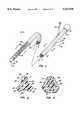
- FIG. 1is a perspective view of a thermal ablation catheter constructed in accordance with the principles of the present invention.
- FIG. 2is a cross-sectional view taken along line 2--2 of FIG. 1.
- FIG. 3is a cross-sectional view taken along line 3--3 of FIG. 1.
- FIG. 4is a detailed elevational view of the distal end of the catheter of FIG. 1.
- FIGS. 5 and 6illustrate alternate cross-sections which would be useful in the construction of catheters according to the present invention.
- FIG. 7illustrates an introducer sheath having an expandable cage at its distal end which is useful for introducing the thermal ablation catheter of the present invention, shown with its expandable cage in a collapsed configuration.
- FIG. 8illustrates the introducer sheath of FIG. 7, shown with its expandable cage in its expanded configuration.
- FIG. 9illustrates the introducer sheath of FIG. 8, shown with the thermal ablation catheter present therein.
- FIG. 10is a schematic illustration of a system for heating and pumping a thermally conductive medium through the catheter of FIG. 1.
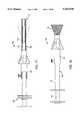
- FIG. 11is a perspective view of an alternative embodiment of a thermal treatment catheter constructed in accordance with the principals of the present invention, wherein a heating element is distributed over a central lumen of the catheter.
- FIG. 12is a cross-sectional view taken along line 12--12 of FIG. 11.
- FIG. 13is an end view of the catheter of FIG. 11.
- FIG. 14is a detailed view of a flow distribution element located at the distal end of the catheter FIG. 11, shown with an expandable cage structure in broken line.
- FIG. 15is a perspective view illustrating a cannula useful for introducing the catheter of FIG. 11 to a uterus.
- FIG. 16is a cross-sectional view taken along line 16--16 of FIG. 15.
- FIGS. 17 and 18are side, elevational views of the catheter FIG. 11.
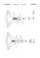
- FIGS. 19-21illustrate use of the catheter of FIG. 11 in thermally treating a uterus according to the present invention.
- FIG. 22illustrates an alternative cage structure for the catheter FIG. 11, further including temperature sensors mounted on penetrating elements on the cage structure.
- FIG. 23illustrates disposition of the cage structure of FIG. 22 within a uterus, with the penetrating elements shown within the endometrial lining of the uterus.
- apparatus and methodsare provided for heating the interior of a wide variety of hollow body organs, cavities, ducts, and passages, particularly including those which have an epithelial lining, endothelial lining, endometrial lining mucous membrane, or other internal surface which may be thermally injured to inactivate the organ and usually to induce necrosis and subsequent fibrosis of the organ itself.
- the present inventionmay be used to provide thermal therapy where the temperature of the surrounding tissue is raised, particularly in the treatment of solid tumors and other neoplastic diseases.
- Exemplary hollow body organs and cavitiesinclude the gallbladder, the uterus, the appendix, the kidney, and the like.
- Exemplary hollow body passages and ductsinclude blood vessels, fistulas, and the like.
- the hollow body organWhen the intent is to inactivate, the hollow body organ will usually be diseased or in some way abnormal prior to treatment according to the present invention.
- an organ or passageWhen the desire is to thermally treat surrounding tissue, an organ or passage may serve merely as an access route. In other cases, it may be desirable to ablate and destroy apparently healthy body organs or parts in order to achieve a desired purpose, e.g., blockage of a blood vessel in a varicocele procedure.
- the phrase "hollow body organ”is intended to embrace hollow body organs, hollow body passages and hollow body cavities.
- the catheter of the present inventioncomprises an elongate member having proximal and distal ends.
- the elongate membermay be flexible or rigid, although flexible catheters are preferred for most applications.
- the length of the catheterwill vary depending on the application, typically being from about 10 cm to 100 cm, usually from about 10 cm to 50 cm, and more usually from about 10 cm to 30 cm, although longer structures will usually be provided for intravascular applications.
- the diameter of the catheterwill also vary depending on the application, typically being at least 1 mm, usually being from 2 mm to 10 mm, with smaller diameters being necessary to access smaller targets and pass through smaller orifices, lumens, and the like.
- the catheterwill typically have a length from 8 cm to 15 cm, and an outer diameter in the range from 2 mm to 6 mm.
- the catheterwill typically have a length from 20 cm to 30 cm typically being about 25 cm, with an outside diameter from 4 mm to 8 mm.
- Rigid elongate membersmay be formed from metals, typically stainless steel, rigid plastics, and the like, while flexible elongate members will typically be formed from extruded organic polymers, such as silicone rubber, polyurethane, polyvinyl chloride, nylon, and the like.
- Elongate memberswill typically include a multiplicity of lumens to provide for fluid communication between the proximal end (which remains outside the patient) to the distal end (present inside the patient during treatment).
- a lumenwill be provided for delivering and aspirating the thermally conductive medium to the hollow body organ.
- Additional lumensmay be provided for delivery of the catheter over a movable guide wire, for venting the hollow body organ while the thermally conductive medium is being delivered, for electrical power and signal connections, and the like.
- a first type of heating means for raising the temperature of the fluid environment surrounding the distal end of the catheterwill be provided at or near the distal tip of the elongate member typically being within about 10 cm of the tip, more typically being within about 5 cm.
- the heating meanswill provide a heated surface for heating fluid surrounding the catheter tip, usually including a resistive heater element.
- the heated surface of the heating meanswill be exposed directly to the environment surrounding the catheter, with little or no insulation covering the surface, in order to enhance heat transfer.
- the heating meanswill be directly exposed to its surrounding environment and will not be enclosed in a housing or other structure which substantially impedes direct heat exchange with surrounding fluid in the body organ.
- the heated surface of the first type of heating meanswill be located over an extended axial length at or near the distal tip of the elongated member.
- the lengthwill usually be from about 1 cm to 8 cm, more usually being about 2 cm to 6 cm, and most usually being about 1.5 to 4 cm.
- the heated surfacewill be suspended over or spaced-apart from the exterior surface of the elongate member to define a circulation region therebetween.
- the thermally conductive fluidwill usually be passed from the central lumen into the circulation region to enhance heating thereof.
- additional heating surface of the elementis exposed to the thermally conductive medium as it is distributed from the catheter.
- the heating elementwill be a permeable or perforate structure in order to increase the total surface area to enhance heat transfer.
- a cylindrical mesh or other perforate cylindrical structuremay find use as a heating element, where the thermally conductive fluid can pass through the interstices or apertures of the structure.
- a preferred heating elementis a coiled structure where an elongate heating element, e.g., a wire, is wrapped in a helix about a supporting structure at the distal end of the elongate member. Successive turns of the helical coil are spaced-apart to permit flow of the thermally conductive medium therethrough and to minimize the thermal effect of adjacent turns on each other. By suspending the heating element away from the elongate member, the exposed surface area of the heating element is maximized, with only the suspension points being blocked.
- an elongate heating elemente.g., a wire
- the heating elementwill be a resistance heating wire having a diameter in the range from about 0.05 mm to 0.25 mm, usually from about 0.1 mm to 0.15 mm, where spacing between successive windings of the coil are from about 0.5 to 2 diameters.
- the number of turns in the heating elementmay vary, typically being from about 3 to 8 turns/mm, more typically being from about 4.5 to 5.5 turns/mm, depending in part on the total length which is to be covered, the linear electrical resistance of the wire, and the desired heat transfer rate.
- the means for suspending the heating element from the surface of the elongate membermay take a variety of forms. For example, it would be possible to form a plurality of discrete support posts on the surface of the elongate member. Alternatively, the coil heating element could be shaped so that it defines integral support posts in its own structure.
- the suspension meanswill comprise a plurality of axial ribs formed in the elongate member itself. At least three ribs will be employed, with troughs between adjacent ribs defining the circulation region between the heater and the elongate member. The use of ribs is preferred since they are relatively easy to fabricate, e.g., by extrusion or other techniques.
- the thermally conductive mediumis introduced through a lumen which extends from the proximal end to distal end of the elongate member.
- the lumenwill open into a plurality of distribution ports at the distal end of the elongate member which permits flow of the thermally conductive medium into and through the recirculation region between the member and the heating element. In this way, heat transfer between the medium being introduced and the heating element can be maximized.
- heating elementwithin the lumen of the catheter which carries the thermally conductive fluid.
- the thermally conductive fluidwill contact the heating element as it is introduced and/or oscillated between the catheter lumen and the interior of the hollow body organ being treated.
- Such heating elements located within the catheter lumenmay be discrete unit heaters, i.e., located over a short distance within the catheter lumen, such as 1 cm or less, but will preferably be distributed over an extended length of the catheter lumen, usually greater than 5 cm, preferably greater than 10 cm, and frequently over the entire length of the catheter lumen.
- a presently preferred heating element located within the catheter lumencomprises an electrical resistance element disposed over the entire surface, usually a wire coil lining the entire lumen of the catheter. Such coils may generally be formed as described above for the exterior heating elements.
- the catheter of the present inventionwill frequently be employed as part of a thermal ablation system comprising, in addition to the catheter, a power supply connected to the heater and a means for inducing an oscillatory flow of thermally conductive medium past the resistive heating element.
- the power supplywill typically include means for controlling the temperature to which the thermally conductive medium is heated by the heating means.
- Such a temperature control systemmay comprise a feedback controller where a temperature sensing element (typically one or more thermocouples or thermistors) is mounted on the catheter and/or an associated introducer sheath (as described in more detail hereinbelow) at a location chosen to accurately measure the heated environment surrounding the catheter, and the energy delivered to the heating means is regulated based on the measured temperature of the medium.
- the temperature control systemwill include temperature sensing element(s) mounted on an expandable cage at the distal end of the introducer sheath. Such element(s) will be in close proximity to the wall of the organ or duct which is being treated, where the temperature is most critical.
- the means for inducing an oscillatory flow of thermally conductive mediumwill typically include a syringe or other pump mechanism which can be connected to the medium introduction lumen in the catheter.
- a syringe or other pump mechanismwhich can be connected to the medium introduction lumen in the catheter.
- the thermal ablation systemoptionally includes the introducer sheath having an expandable structure or cage near its distal end.
- the introducer sheathwill be used to introduce the thermal ablation catheter and to expand the portion of the hollow body organ in which the heating element of the catheter is positioned.
- the expanded cagecan thus both protect the organ wall from direct contact with the heating element and position the heating element and optionally fluid diffuser near the center of the organ so that heat is uniformly distributed to all portions of the organ.
- the cage structure on the introducer sheathpreferably comprises a plurality of axially aligned fingers which can be introduced in a collapsed configuration and expanded within the hollow body organ or duct in order to provide the desired expanded cage structure.
- a cagewill be substantially open so that the inner wall of the organ or duct will be completely exposed to the thermally conductive medium which is being heated by the catheter.
- the fingersmay be spring-loaded to open when they are released within the body organ or duct, or a separate means may be provided for mechanically causing the opening.
- Other designs, such as the use of shape and heat memory alloys,may also find use. Regardless of the particular construction, it will be particularly preferred to provide one or more temperature sensing elements on at least some of the finger elements which form the expandable cage.
- the temperature sensing elementswill be located at the point(s) of maximum radial expansion on the cage. In this way, the temperature sensing elements will be located immediately adjacent to the inner wall of the hollow body organ during the thermal treatment procedure and will thus be able to accurately measure the localized temperature at the point of thermal impact.
- a cage structure generally as described abovemay be mounted directly on the thermal delivery catheter.
- the cage structurecomprises a plurality of resilient elements or rods which, in an unconstrained configuration, define a shape which nests within the hollow body organ being treated.
- the catheter and caged structurecan be introduced through a suitable cannula or sheath with the cage structure in a collapsed configuration. After the cage structure passes out of the cannula or sheath, the cage structure will expand to its unconstrained configuration, preferably engaging the interior wall of the hollow body organ to open the organ to receive the thermally conductive medium.
- Use of such resilient cage structuresis not essential, and the present invention encompasses the use of mechanical structures which may be positively expanded and collapsed using appropriate mechanical linkages in order to facilitate introduction of the cage structure and subsequent enlargement of the cage structure to the desired final configuration.
- a flow directing elementmay be mounted on the thermal treatment catheter in order to direct flow of the thermally conductive medium as it is expelled from the lumen of the catheter.
- flow directing elementswill be located within an expansible cage structure, as described above, where the cage structure fixes the position of the distal end of the catheter body within the hollow body organ or lumen and facilitates proper alignment of the flow directing element within the hollow body organ being treated.
- the flow directing elementwill usually include at least two ports, wherein each port is oriented in a predetermined manner in order to direct heated fluid toward a region of the hollow body organ which might otherwise receive insufficient heating.
- the flow directing elementis particularly useful with catheters having internal heating elements, where the fluid expelled from the catheter will be heated to the maximum desirable temperature.
- the flow directing elementincludes at least two ports which diverge from each other at an angle in the range from 30° to 180° usually between 60° and 150° which are oriented to direct fluid against the cornua regions of the uterus which is being treated.
- temperature sensors on the expandable cagewill comprise penetrating elements which, when engaged against an adjacent hollow body lining, will dispose the temperature sensor at a preselected depth beneath the surface of the lining.
- the depthwill be in the range from 1 mm to 20 mm, preferably being between 2 mm and 6 mm.
- the method of the present inventionrelies on introducing the thermally conductive medium into the interior of the hollow body organ in such a way that the organ is filled with the medium and the medium is in good thermal contact with substantially the entire interior surface of the organ.
- the heating elementthen transfers heat directly to the thermally conductive medium which in turn transfers the heat to the organ wall by convection.
- the temperature of the epithelial lining, endothelial lining, endometrial lining, or mucous membrane of the body organcan be raised to a preselected temperature for a preselected minimum time period in order to permanently injure the lining and/or deactivate the organ.
- the gallbladderIn the case of gallbladder treatment, the gallbladder will usually be treated at a temperature and for a time sufficient to ablate the organ and cause resorption. In the case of uterine treatment, it will often be sufficient to injure the endometrial lining so that scar tissue is formed, thus presenting uterine bleeding which is often the condition being treated.
- the thermally conductive mediumcan be virtually any physiologically-compatible liquid, solution, slurry, gel, or the like, which can be percutaneously or directly introduced into the interior of the hollow body organ. Exemplary thermally conductive media include water, normal saline, contrast media, physiological irrigating solution, and the like. Alternatively, natural body fluids within the organ can provide a portion or all of the thermally conductive fluid.
- Thermal treatmentincludes but is not limited to thermal ablation.
- ablationmeans any injury or damage to the hollow body organ and/or connecting ducts and body passages which results in deactivation of the function of the organ, usually resulting in necrosis and eventual resorption of the organ. The resorption will typically occur over an extended period of weeks, months, or longer.
- Other thermal treatmentparticularly of the endometrial ling of the uterus, will result in scar formation only, not causing necrosis or resorption of the organ.
- the thermally conductive mediummay be introduced to the interior of the hollow body organ at a temperature below that which will have a deleterious effect on the tissue and organs surrounding the hollow body organ being treated.
- the temperaturewill usually be below about 42° C., more usually being at body temperature (37° C.) or room temperature (about 20° C.).
- it may be desirable to introduce the contrast medium above body temperatureusually in the range from about 37° C. to 42° C., in order to shorten the time necessary to raise the temperature of the medium to the treatment temperature, discussed hereinafter.
- the temperature of the thermally conductive mediumwill be raised and/or maintained above a threshold level which results in injury to the endothelial lining, epithelial lining, endometrial lining, or mucous membrane.
- the threshold temperaturewill generally be above 42° C., usually being in the range from 45° C. to 90° C., more usually being in the range from 50° C. to 85° C., and preferably being in the range from about 54° C. to 85° C.
- Preferred temperatures for the treatment of the gallbladder and the uterusare set forth above.
- the thermally conductive mediumwill be maintained above the threshold temperature for a period of time in the range from about 1 to 60 minutes, usually being in the range from about 5 to 40 minutes, and preferably being in the range from about 15 to 35 minutes.
- the temperature of the thermally conductive mediumwill be raised as rapidly as possible and maintained at a substantially constant treatment temperature for the desired treatment period.
- the treatment temperaturemay vary or be varied during the treatment period with the total treatment time being adjusted to take the variation in organ size, heat transfer characteristics, thermally conductive medium perfusion rate, temperature limitations, and the like into account.
- the method of the present inventionrelies on alternately aspirating and expelling incremental volumes of the medium through the catheter.
- Such an oscillatory flowhas been found to significantly enhance temperature uniformity (through mixing of the medium) as well as heat transfer (through continuous reversing flow of medium through and past the heating element). Both the enhanced temperature uniformity and the increased heat transfer rate allow the thermal ablation procedures to reduce the total amount of heat delivered to the organ as well as the temperature of the heating surfaces required to deliver that amount of heat.
- the volume which is aspiratedwill usually be substantially the same as the volume which is expelled.
- the aspirated and expelled volumeswill be in the range from about 0.1 ml to 5 ml, more usually being from about 1 ml to 2.5 ml, and the frequency of oscillation will be in the range from about 10 to 60 cycles/minute, typically being in the range from about 30 to 50 cycles/minute.
- temperature of the tissue being treatedwill be monitored and controlled, rather than monitoring of the temperature of the thermally conductive fluid.
- temperatureis monitored using one or more temperature sensors disposed against the interior lining of the hollow body organ.
- temperature sensorsmay be mounted on the distal cage structure on the catheter, preferably with two or more sensors being strategically located to monitor different portions of the organ which would be expected to be heated at different rates.
- the tissue temperaturewill be monitored at a preselected depth below the interior surface of the hollow body organ.
- Such monitoringcan be performed using temperature probes which penetrate the tissue to the desired depth, typically in the range from 1 mm to 20 mm, preferably in the range from 2 mm to 6 mm.
- the temperature probesare penetrating elements mounted on the expansible cage structure which is on the thermal treatment catheter.
- the thermal energy being delivered to the mediumwill be terminated.
- the thermally conductive mediummay then be aspirated from the hollow body organ, typically using the same catheter which was employed to deliver the medium and raise the temperature of the medium as described above.
- the thermally conductive mediumwill not be aspirated until the temperature has decreased sufficiently so that its withdrawal will not expose tissues and organs surrounding the catheter to risk.
- the withdrawal temperaturewill be below about 42° C., preferably being below about 40° C.
- the thermally conductive mediumcan be left within the hollow body organ where it will be resorbed or eliminated by normal physiological processes.
- the catheter 10includes an elongate element or body 12 having a proximal end 14 and a distal end 16.
- the catheter body 12has a cross-sectional profile including three rib elements 18 separated by three trough regions 20.
- the elongate body 12further includes four lumens 22, 24, 26, and 28 extending generally from the proximal end 14 to or close to the distal end 16.
- the elongate catheter body 12, as illustrated,is shown to be flexible along substantially its entire length.
- portions of the catheter body 12may be constructed from rigid or semi-rigid materials, for a desired purpose.
- Metals or other heat conductive materialsmight find use in such designs.
- Other reasons for departing from the generally flexible nature of the catheter body 12may occur to those skilled in the art while remaining within the scope of the present invention.
- a pair of temperature sensor leads 30enter the first lumen 22 near the distal end 14 of the catheter body 12 and terminate at external temperature sensors 32 at the distal end 16.
- the temperature sensor leads 30will not be necessary when temperature sensing elements are provided only on the expandable cage of the introducer sheath, as described in more detail hereinafter.
- a first power lead 34enters lumen 24 at the proximal end of the catheter while a second power lead 36 enters lumen 26 at the proximal end of the catheter.
- the power leads 34 and 36are connected to a heating coil 40 wrapped about and extended axial length near the distal tip of the catheter 10.
- lumen 22may be used as an auxiliary perfusion and/or aspiration lumen.
- Central lumen 28is connected to a plurality of radial apertures 42 which open into the three trough regions 20 which are located beneath the heating coil 40. In this way, the thermally conductive medium can be introduced through a connector 46 at the proximal end of the catheter 10 and in turn be distributed through the various radial apertures 42 which open into a circulation region defined by the trough regions 20 of the catheter body 12.
- Central lumen 28terminates in a port 29 located at the distal tip of the catheter body 12. Usually, the diameter of the port 29 will be smaller than that of the lumen 28 so that there will be a close fit about the center wire (not illustrated) which is used for introducing the catheter 10.
- the heating coil 40is wrapped around the catheter body 10 so that it is suspended on the axial ribs 18. Portions of the heating coil 40 which are between the axial ribs 18 are thus completely exposed to the surrounding environment. In particular, the wires are exposed to the thermally conductive medium as it is released or expelled through the axial apertures 42 as well as when it is aspirated back into the catheter through said apertures. Heat transfer or flux from the heating coil 40 will be a compromise between maximizing the total wire length and providing sufficient spacing between adjacent turns of the wire to increase exposure and permit free flow of thermally conductive medium therethrough. That is, the total wire length (which increases the total surface area of the wire) is increased by having a higher number of turns on the catheter.
- Too high a turn densitylimits both the effective exposed area of each turn and limits the flow of thermally conductive medium through the coil 40.
- An optimum compromise heat transfercan be achieved when the spacing s (FIG. 4) between adjacent turns of the coil 40 is equal to from about 0.5 to 2 times the wire diameter d.
- the wire diameterwill usually be in the range from about 0.05 mm to 0.75 mm, with the spacing between adjacent turns of the coil being from about 0,025 mm to 0.25 mm.
- FIGS. 5 and 6alternate catheter body cross sections having different numbers of axial ribs are illustrated.
- the number of axial ribsis not critical, but it will be appreciated that at least three ribs will usually be required.
- the introducer sheath 50includes an outer sheath member 52 and an inner sheath member 54.
- the inner sheath member 54includes an expandable cage 56 at its distal end and a centering wire 58 extending throughout its length.
- the outer sheath 52 and inner sheath 54will be configured as nested tubes which are capable of sliding relative to each other.
- the tubesmay be rigid or flexible, usually being flexible to facilitate introduction through relatively tortuous paths.
- the cage 56includes a plurality of resilient fingers 57 (only two are illustrated) which are constrained in a collapsed configuration within the distal end of outer sheath member 52.
- the individual fingers 57will be connected together at their distal ends so that, when released from the outer sheath 52, they will spring into the expanded configuration illustrated in FIG. 8. It would also be possible to leave the individual fingers 57 unconnected at their distal end so that they remain free to expand away from each other.
- the cage 56may also be configured so that it is expanded by pulling proximally on the centering wire 58 to axially compress the cage, forcing its radial expansion. A variety of other specific designs will be apparent to those skilled in the art. It is critical only that the cage 56 be expandable within the target body organ and that, when expanded, it cover or block a minimum area of the inner surface of the body organ.
- the introducer sheath 50will be inserted into a hollow body organ, typically through adjacent passages and ducts in a conventional manner, with the expandable cage 56 in a collapsed configuration held within the outer sheath 52. Once the introducer sheath is in position, the outer sheath member 52 will be translated relative to the inner sheath member 54 so that the cage 56 is freed to assume its expanded configuration, as illustrated in FIG. 8. Usually, a seal member 60 will be provided to seal against the outer sheath member.
- Temperature sensors 61may be disposed on at least some of the fingers 57 of the expandable cage 56. Preferably, at least two fingers 57 will include at least one temperature sensor 61. More preferably, at least one sensor will be located at the point of maximum expansion as illustrated for sensors 61 in FIGS. 8 and 9. In this way, the temperature sensors 61 will be located immediately adjacent to the endothelium or mucosa of the hollow body organ during treatment.
- the thermal ablation catheter 10can be introduced over the centering wire 58 so that the heating element 40 is positioned within the expanded cage 56.
- the heating element 40can be optimally positioned within the hollow body organ and direct contact between the heating element and the interior surfaces of the organ prevented.
- a second seal 62will be provided on the catheter 10 in order to seal against the proximal end of the inner sheath 54.
- the systemincludes a power supply and controller 70 which is connected to the sensor leads 30 and power leads 34 and 36.
- the power supply and controllermay be connected to a mechanical actuator 72 which drives a syringe assembly 74 to create a reciprocating pump mechanism.
- the mechanical drivemay be separately actuated and controlled.
- the syringe 74in turn, is connected to a three-way valve 76 which permits the introduction of the thermally conductive medium from a reservoir 77 into connecting tube 78.
- Connecting tube 78is connected to the hub connector 46 on the thermal ablation catheter 10.
- valve 76can optionally be switched to connect the syringe mechanism 74 and the desired oscillating flow of medium induced by starting the actuator 72.
- the desired volume, frequency, and the like,can be controlled through the power supply and control system 70 or by independent controls within the actuator 72 itself.
- the reservoir 77will be open to the atmosphere, and the level of liquid therein will be disposed above the valve 76 and catheter 10 by a distance to provide a desired constant fluid pressure within the organ being treated, usually in the range from about 10 mmHG to 60 mmHG.
- the use of an open reservoirhas a number of advantages. It provides a bleed path for releasing entrapped air and other gases from the oscillating thermally conductive medium. It also protects against accidental over pressure from the syringe assembly 74. Additionally, the reservoir assures that there will be sufficient fluid to maintain the desired base line fluid pressure within the organ being treated and provides a visual indicator of fluid volume and mixing efficiency.
- the power to the heating coil 40will be controlled to achieve a desired temperature, based on the temperature sensors 32 and/or 61.
- the fluid temperaturewill be in the range from about 53° C. to 60° C.
- the catheter 10may be introduced to a hollow body organ, such as the gallbladder, by techniques described in co-pending application Ser. Nos. 07/407,839; 07/529,077; and 07/551,971; the disclosures of which have previously been incorporated herein by reference.
- the optimum temperature of the mediumwill be from about 54° C. to 60° C. (usually corresponding to a heating element surface temperature of from about 70° C. to 90° C.), the optimum oscillation frequency will be from about 10 to 50 cycles/minute, the oscillation volume from about 0.1 ml to 2.5 ml, and the total treatment time from about 15 minutes to 35 minutes.
- the catheter 100includes an elongate element or body 102 having a proximal end 104 and a distal end 106.
- the catheter body 102is tubular having a wire coil heating element 110 formed over an axial lumen 112 thereof.
- a proximal housing 114typically in the form of a conventional Y-connector, includes a proximal port 116 for connection to a source of thermally conductive fluid, such as a combined power supply and oscillatory pump, as illustrated in FIG. 10.
- a conventional compression fittingwill be provided on the port 116 to allow connection via tubing.
- a second port 118 on the housing 114provides for a power connector 120, which is connected to the wire coil heating element 110, and a plurality of temperature sensing leads 122, typically being thermocouple connectors.
- the leads 122will be connected to thermocouple 124 located on a cage structure 130, attached to the distal end 106 of the elongate catheter body 102.
- the cage structure 130comprises four resilient elements or "ribs" 132 which are secured at a proximal end of the distal end of the catheter body 102 and to each other by means of a distal button 134.
- the individual elements 132will be formed of a resilient material, such as spring steel, shape memory alloy, heat memory alloy (e.g., Nitinol®), or the like.
- the cage structure 130will be introduced to the hollow body organ in a collapsed configuration within a suitable cannula or sheath, and will thereafter expand to the open configuration, as illustrated in FIGS. 11, 13, and 14.
- a flow distributing element 140is connected via a short tube 142 to the distal end of lumen 112 through catheter body 102.
- the flow distributing element 140includes a plurality of flow ports 144 which are oriented to distribute flow in a preselected pattern. As best seen in FIG. 14, three flow ports 144 may be provided in order to direct flow in three diverging directions within a single plane. Such a configuration is particularly useful for thermal treatment of the uterus, as described hereinafter, where the outermost ports are generally directed at the cornua regions of the uterus which might otherwise receive insufficient heating from the catheter 100. Divergent angles ⁇ , and ⁇ 2 will usually be from 30° to 75° , thus subtending a total angle in the range from 60° to 150°.
- the access cannula 150comprises an elongate body having a total length from about 20 cm to 40 cm and having an access lumen 154 extending from a distal end 156 to a proximal end 158 thereof. Construction and use of the uterine access cannula 150 is described in detail in co-pending application Ser. No. 03/266036, filed on the same date as the present application.
- the cannula body 152includes an inner tubular shaft 156, an outer tubular shaft 158, and an axially translatable outer cervical seal member 160, an expansible region 162, typically a cylindrical mesh, forms the distal region of the outer tubular shaft 158.
- an expansible region 162typically a cylindrical mesh, forms the distal region of the outer tubular shaft 158.
- the expansible region 162will be collapsed.
- the expansible region 162will be axially compressed so that its distal end expands radially to form a conical surface, as illustrated in broken line in FIGS. 15 and 17 and in full line in FIG. 18.
- such expanded conical surfacewill form an inner cervical seal when the cannula 150 is introduced through the cervix into the uterus.
- the outer cervical seal member 60may be axially translated relative to the inner cervical seal, so that the two seals may be brought together as illustrated in FIG. 18.
- FIGS. 19-21use of the catheter 100 and uterine access cannula 150 in thermal treatment of a uterus U will be described.
- Access to the cervical osis obtained in a conventional manner.
- the uterine access cannula 115is introduced through the os while the inner cervical seal 116 is in its collapsed configuration, as illustrated in FIG. 19.
- the expansible region 162is then expanded, as illustrated in FIG. 20, and drawn proximally outward so that it seals against the inner surface of the cervix.
- the outer cervical seal member 160is then advanced distally so that the inner and outer surfaces of the cervix are engaged by the inner seal 162 and outer seal 160, respectfully.
- the cannula 150thus provides a generally fluid tight seal about its periphery so that heated thermally conductive medium which is introduced as described hereinafter cannot leak around the cannula outwardly into the vagina.
- catheter 100is introduced through the central lumen of the cannula.
- the catheter 100will be introduced so that cage structure 130 at its distal end expands into the interior of the uterus, maintaining an open volume for thermal treatment.
- the flow distributing element 140will thus be located within the interior of the uterus so that fluid flow therefrom is directed toward the cornua regions C, in order to enhance thermal transfer to these regions.
- the center port 144 of the flow distributing element 140will direct fluid centrally within the uterine cavity.
- temperature sensing elements 170may be provided on its exterior surface over the regions where leakage might be expected. Means for monitoring the temperatures of these elements (not illustrated) is provided. Thus, if an unexpected temperature rise is detected, heated fluid can rapidly be withdrawn and treatment stopped until a better seal is achieved.
- Heat treatmentcan be achieved by introducing a heated or unheated thermally conductive medium through the catheter 100 using connector tube 172.
- the connector tubewill be connected to a suitable heating and oscillatory pumping system, such as illustrated in FIG. 10.
- the systemwill deliver electrical energy to the internal heating coils 110, while fluid is oscillated back and forth within the uterine cavity. Volumes and temperatures will generally be controlled as described above.
- the treatmentwill be continued for a time sufficient to induce necrosis of the endometrial lining of the uterus.
- the temperature sensing systemcomprises a plurality of temperature sensing elements 200, typically thermocouples, which are located at the distal end of penetrating elements 202 which are disposed about individual resilient elements 204 of a cage structure 206 mounted at the distal end of a catheter body 208.
- the penetrating elements 202are disposed generally radially outward from the cage structure so that they will penetrate by a predetermined depth into the uterine wall as illustrated in FIG. 23.
- the penetrating elements 202will generally be resilient members which are collapsed while the catheter is introduced through a suitable cannula but which will spring back to the desired configuration when the catheter is released.
- the penetrating members 202will thus be able to penetrate into the uterine wall as illustrated.
- the length of the penetrating members 202will typically be in the range from 1 mm to 20 mm, preferably from 2 mm to 6 mm, corresponding to the desired penetration depth for measuring temperature.
Landscapes
- Health & Medical Sciences (AREA)
- Surgery (AREA)
- Engineering & Computer Science (AREA)
- Life Sciences & Earth Sciences (AREA)
- Biomedical Technology (AREA)
- Molecular Biology (AREA)
- Nuclear Medicine, Radiotherapy & Molecular Imaging (AREA)
- Plasma & Fusion (AREA)
- Physics & Mathematics (AREA)
- Heart & Thoracic Surgery (AREA)
- Medical Informatics (AREA)
- Otolaryngology (AREA)
- Animal Behavior & Ethology (AREA)
- General Health & Medical Sciences (AREA)
- Public Health (AREA)
- Veterinary Medicine (AREA)
- Surgical Instruments (AREA)
- Media Introduction/Drainage Providing Device (AREA)
Abstract
Description
Claims (79)
Priority Applications (1)
| Application Number | Priority Date | Filing Date | Title |
|---|---|---|---|
| US08/266,037US5542928A (en) | 1991-05-17 | 1994-06-27 | Method and device for thermal ablation having improved heat transfer |
Applications Claiming Priority (3)
| Application Number | Priority Date | Filing Date | Title |
|---|---|---|---|
| US70279691A | 1991-05-17 | 1991-05-17 | |
| US08/073,639US5433708A (en) | 1991-05-17 | 1993-06-07 | Method and device for thermal ablation having improved heat transfer |
| US08/266,037US5542928A (en) | 1991-05-17 | 1994-06-27 | Method and device for thermal ablation having improved heat transfer |
Related Parent Applications (1)
| Application Number | Title | Priority Date | Filing Date |
|---|---|---|---|
| US08/073,639Continuation-In-PartUS5433708A (en) | 1991-05-17 | 1993-06-07 | Method and device for thermal ablation having improved heat transfer |
Publications (1)
| Publication Number | Publication Date |
|---|---|
| US5542928Atrue US5542928A (en) | 1996-08-06 |
Family
ID=26754718
Family Applications (1)
| Application Number | Title | Priority Date | Filing Date |
|---|---|---|---|
| US08/266,037Expired - LifetimeUS5542928A (en) | 1991-05-17 | 1994-06-27 | Method and device for thermal ablation having improved heat transfer |
Country Status (1)
| Country | Link |
|---|---|
| US (1) | US5542928A (en) |
Cited By (294)
| Publication number | Priority date | Publication date | Assignee | Title |
|---|---|---|---|---|
| US5672174A (en) | 1995-08-15 | 1997-09-30 | Rita Medical Systems, Inc. | Multiple antenna ablation apparatus and method |
| US5672173A (en) | 1995-08-15 | 1997-09-30 | Rita Medical Systems, Inc. | Multiple antenna ablation apparatus and method |
| US5683384A (en) | 1993-11-08 | 1997-11-04 | Zomed | Multiple antenna ablation apparatus |
| US5728143A (en)* | 1995-08-15 | 1998-03-17 | Rita Medical Systems, Inc. | Multiple antenna ablation apparatus and method |
| US5735817A (en)* | 1995-05-19 | 1998-04-07 | Shantha; T. R. | Apparatus for transsphenoidal stimulation of the pituitary gland and adjoining brain structures |
| US5735847A (en) | 1995-08-15 | 1998-04-07 | Zomed International, Inc. | Multiple antenna ablation apparatus and method with cooling element |
| US5782827A (en) | 1995-08-15 | 1998-07-21 | Rita Medical Systems, Inc. | Multiple antenna ablation apparatus and method with multiple sensor feedback |
| US5810804A (en) | 1995-08-15 | 1998-09-22 | Rita Medical Systems | Multiple antenna ablation apparatus and method with cooling element |
| WO1998043531A1 (en) | 1997-04-01 | 1998-10-08 | Vilos George A | Debris aspirating resectoscope |
| WO1998056324A1 (en)* | 1997-06-13 | 1998-12-17 | Arthrocare Corporation | Electrosurgical systems and methods for recanalization of occluded body lumens |
| US5860426A (en)* | 1996-11-06 | 1999-01-19 | Kleiman; Aldo Sergio | Cholecystoscopic cannula and cholecystoscopic gallbladder laser-sclerosis procedure |
| US5863290A (en) | 1995-08-15 | 1999-01-26 | Rita Medical Systems | Multiple antenna ablation apparatus and method |
| US5891094A (en)* | 1995-09-07 | 1999-04-06 | Innerdyne, Inc. | System for direct heating of fluid solution in a hollow body organ and methods |
| US5913855A (en) | 1995-08-15 | 1999-06-22 | Rita Medical Systems, Inc. | Multiple antenna ablation apparatus and method |
| US5919187A (en)* | 1990-03-13 | 1999-07-06 | The Regents Of The University Of California | Method and apparatus for endovascular thermal thrombosis and thermal cancer treatment |
| US5925042A (en) | 1995-08-15 | 1999-07-20 | Rita Medical Systems, Inc. | Multiple antenna ablation apparatus and method |
| US5928229A (en) | 1993-11-08 | 1999-07-27 | Rita Medical Systems, Inc. | Tumor ablation apparatus |
| US5951547A (en) | 1995-08-15 | 1999-09-14 | Rita Medical Systems, Inc. | Multiple antenna ablation apparatus and method |
| US5964752A (en)* | 1998-02-02 | 1999-10-12 | Stone; Kevin R. | Articular cartilage surface shaping apparatus and method |
| US5980517A (en) | 1995-08-15 | 1999-11-09 | Rita Medical Systems, Inc. | Cell necrosis apparatus |
| US5984861A (en)* | 1997-09-29 | 1999-11-16 | Boston Scientific Corporation | Endofluorescence imaging module for an endoscope |
| US5984965A (en)* | 1997-08-28 | 1999-11-16 | Urosurge, Inc. | Anti-reflux reinforced stent |
| US6047700A (en)* | 1998-03-30 | 2000-04-11 | Arthrocare Corporation | Systems and methods for electrosurgical removal of calcified deposits |
| US6059780A (en) | 1995-08-15 | 2000-05-09 | Rita Medical Systems, Inc. | Multiple antenna ablation apparatus and method with cooling element |
| US6066132A (en)* | 1998-06-30 | 2000-05-23 | Ethicon, Inc. | Articulating endometrial ablation device |
| US6071280A (en) | 1993-11-08 | 2000-06-06 | Rita Medical Systems, Inc. | Multiple electrode ablation apparatus |
| US6080151A (en)* | 1997-07-21 | 2000-06-27 | Daig Corporation | Ablation catheter |
| US6080150A (en) | 1995-08-15 | 2000-06-27 | Rita Medical Systems, Inc. | Cell necrosis apparatus |
| US6090105A (en) | 1995-08-15 | 2000-07-18 | Rita Medical Systems, Inc. | Multiple electrode ablation apparatus and method |
| US6096065A (en)* | 1997-09-29 | 2000-08-01 | Boston Scientific Corporation | Sheath for tissue spectroscopy |
| US6119031A (en)* | 1996-11-21 | 2000-09-12 | Boston Scientific Corporation | Miniature spectrometer |
| US6132425A (en) | 1995-08-15 | 2000-10-17 | Gough; Edward J. | Cell necrosis apparatus |
| US6179824B1 (en)* | 1993-05-10 | 2001-01-30 | Arthrocare Corporation | System and methods for electrosurgical restenosis of body lumens |
| US6185443B1 (en) | 1997-09-29 | 2001-02-06 | Boston Scientific Corporation | Visible display for an interventional device |
| US6183469B1 (en) | 1997-08-27 | 2001-02-06 | Arthrocare Corporation | Electrosurgical systems and methods for the removal of pacemaker leads |
| WO2001012061A1 (en)* | 1999-08-18 | 2001-02-22 | Alsius Corporation | Central venous catheter with heat exchange properties |
| US6238393B1 (en) | 1998-07-07 | 2001-05-29 | Medtronic, Inc. | Method and apparatus for creating a bi-polar virtual electrode used for the ablation of tissue |
| US6245026B1 (en)* | 1996-07-29 | 2001-06-12 | Farallon Medsystems, Inc. | Thermography catheter |
| US20010003800A1 (en)* | 1996-11-21 | 2001-06-14 | Steven J. Frank | Interventional photonic energy emitter system |
| US6289229B1 (en) | 1998-01-20 | 2001-09-11 | Scimed Life Systems, Inc. | Readable probe array for in vivo use |
| US6302903B1 (en) | 1998-07-07 | 2001-10-16 | Medtronic, Inc. | Straight needle apparatus for creating a virtual electrode used for the ablation of tissue |
| US6315777B1 (en) | 1998-07-07 | 2001-11-13 | Medtronic, Inc. | Method and apparatus for creating a virtual electrode used for the ablation of tissue |
| US6324418B1 (en) | 1997-09-29 | 2001-11-27 | Boston Scientific Corporation | Portable tissue spectroscopy apparatus and method |
| US6327505B1 (en) | 1998-05-07 | 2001-12-04 | Medtronic, Inc. | Method and apparatus for rf intraluminal reduction and occlusion |
| WO2002039079A1 (en)* | 2000-11-10 | 2002-05-16 | Cardiostream, Inc. | Guidewire having extendable contact sensors for measuring temperature of vessel walls |
| US6394949B1 (en) | 1998-10-05 | 2002-05-28 | Scimed Life Systems, Inc. | Large area thermal ablation |
| US20020068930A1 (en)* | 1995-11-22 | 2002-06-06 | Arthrocare Corporation | Systems and methods for electrosurgical tendon vascularization |
| US6405073B1 (en) | 1997-07-22 | 2002-06-11 | Scimed Life Systems, Inc. | Miniature spectrometer system and method |
| US20020077564A1 (en)* | 1996-07-29 | 2002-06-20 | Farallon Medsystems, Inc. | Thermography catheter |
| WO2002047567A1 (en)* | 2000-12-11 | 2002-06-20 | Boston Scientific Limited | Radio frequency ablation system |
| US6409747B1 (en) | 1998-04-21 | 2002-06-25 | Alsius Corporation | Indwelling heat exchange catheter and method of using same |
| US6409722B1 (en) | 1998-07-07 | 2002-06-25 | Medtronic, Inc. | Apparatus and method for creating, maintaining, and controlling a virtual electrode used for the ablation of tissue |
| US6424696B1 (en) | 2000-11-10 | 2002-07-23 | Scimed Life Systems, Inc. | X-ray catheter using a step-up transformer |
| US6443947B1 (en) | 2000-03-01 | 2002-09-03 | Alexei Marko | Device for thermal ablation of a cavity |
| US6475168B1 (en) | 2000-11-10 | 2002-11-05 | Scimed Life Systems, Inc. | Guide wire having x-ray transparent window for x-ray catheter |
| US6493589B1 (en) | 1998-05-07 | 2002-12-10 | Medtronic, Inc. | Methods and apparatus for treatment of pulmonary conditions |
| US6494893B2 (en) | 1993-03-05 | 2002-12-17 | Innderdyne, Inc. | Trocar system having expandable port |
| US6494902B2 (en) | 1998-07-07 | 2002-12-17 | Medtronic, Inc. | Method for creating a virtual electrode for the ablation of tissue and for selected protection of tissue during an ablation |
| US6509521B1 (en) | 2000-11-10 | 2003-01-21 | Scimed Life Systems, Inc. | X-ray catheter with coaxial conductor |
| US6529775B2 (en) | 2001-01-16 | 2003-03-04 | Alsius Corporation | System and method employing indwelling RF catheter for systemic patient warming by application of dielectric heating |
| US6530946B1 (en) | 1998-04-21 | 2003-03-11 | Alsius Corporation | Indwelling heat exchange heat pipe catheter and method of using same |
| US6537248B2 (en) | 1998-07-07 | 2003-03-25 | Medtronic, Inc. | Helical needle apparatus for creating a virtual electrode used for the ablation of tissue |
| US6537272B2 (en) | 1998-07-07 | 2003-03-25 | Medtronic, Inc. | Apparatus and method for creating, maintaining, and controlling a virtual electrode used for the ablation of tissue |
| US6540655B1 (en) | 2000-11-10 | 2003-04-01 | Scimed Life Systems, Inc. | Miniature x-ray unit |
| US6540720B1 (en) | 2000-11-10 | 2003-04-01 | Scimed Life Systems, Inc. | Miniature x-ray unit |
| US6546080B1 (en) | 2000-11-10 | 2003-04-08 | Scimed Life Systems, Inc. | Heat sink for miniature x-ray unit |
| US6551278B1 (en) | 2000-11-10 | 2003-04-22 | Scimed Life Systems, Inc. | Miniature x-ray catheter with retractable needles or suction means for positioning at a desired site |
| US6554757B1 (en) | 2000-11-10 | 2003-04-29 | Scimed Life Systems, Inc. | Multi-source x-ray catheter |
| US6558375B1 (en) | 2000-07-14 | 2003-05-06 | Cardiofocus, Inc. | Cardiac ablation instrument |
| US6565530B2 (en)* | 2001-02-28 | 2003-05-20 | Scimed Life Systems, Inc. | Immobilizing objects in the body |
| US6579285B2 (en) | 1994-09-09 | 2003-06-17 | Cardiofocus, Inc. | Photoablation with infrared radiation |
| US20030199809A1 (en)* | 1998-07-08 | 2003-10-23 | Orth Michael J. | Methods, systems, and kits for implanting articles |
| US6641603B2 (en) | 2001-04-13 | 2003-11-04 | Alsius Corporation | Heat exchange catheter having helically wound reinforcement |
| US20040002698A1 (en)* | 2002-06-26 | 2004-01-01 | Ethicon, Inc. | Thermal ablation with deployable cage |
| US6676656B2 (en) | 1994-09-09 | 2004-01-13 | Cardiofocus, Inc. | Surgical ablation with radiant energy |
| US6689127B1 (en) | 1995-08-15 | 2004-02-10 | Rita Medical Systems | Multiple antenna ablation apparatus and method with multiple sensor feedback |
| US20040039247A1 (en)* | 2002-08-23 | 2004-02-26 | Nash John Edward | Catheters |
| US6702810B2 (en) | 2000-03-06 | 2004-03-09 | Tissuelink Medical Inc. | Fluid delivery system and controller for electrosurgical devices |
| US6709448B2 (en) | 2001-04-13 | 2004-03-23 | Alsius Corporation | Open core heat exchange catheter, system and method |
| US6716236B1 (en) | 1998-04-21 | 2004-04-06 | Alsius Corporation | Intravascular catheter with heat exchange element having inner inflation element and methods of use |
| US6746447B2 (en) | 1993-05-10 | 2004-06-08 | Arthrocare Corporation | Methods for ablating tissue |
| US6763836B2 (en) | 1998-06-02 | 2004-07-20 | Arthrocare Corporation | Methods for electrosurgical tendon vascularization |
| US20040143259A1 (en)* | 1998-07-07 | 2004-07-22 | Medtronic, Inc. | Method and apparatus for creating a bi-polar virtual electrode used for the ablation of tissue |
| US20040143253A1 (en)* | 2003-01-17 | 2004-07-22 | Vanney Guy P. | Ablation catheter assembly having a virtual electrode comprising portholes |
| US20040143256A1 (en)* | 2003-01-21 | 2004-07-22 | Bednarek Michael C. | Ablation catheter and electrode |
| US20040143254A1 (en)* | 2003-01-21 | 2004-07-22 | Vanney Guy P. | Catheter design that facilitates positioning at tissue to be diagnosed or treated |
| US20040147913A1 (en)* | 1999-08-25 | 2004-07-29 | Cardiofocus, Inc. | Surgical ablation instruments with irrigation features |
| US20040167503A1 (en)* | 1999-08-25 | 2004-08-26 | Cardiofocus, Inc. | Malleable surgical ablation instruments |
| US20040172041A1 (en)* | 2002-11-22 | 2004-09-02 | Gresham Richard D. | Sheath introduction apparatus and method |
| US20040199121A1 (en)* | 2001-08-01 | 2004-10-07 | Thomas Wenchell | Apparatus and method for providing percutaneous access and medicament to a target surgical site |
| US20040215296A1 (en)* | 1999-11-16 | 2004-10-28 | Barrx, Inc. | System and method for treating abnormal epithelium in an esophagus |
| US20040236324A1 (en)* | 1995-02-22 | 2004-11-25 | Medtronic, Inc. | Pen-type electrosurgical instrument |
| US20050004565A1 (en)* | 2003-07-02 | 2005-01-06 | Guy Vanney | Ablation fluid manifold for ablation catheter |
| US20050010212A1 (en)* | 2000-03-06 | 2005-01-13 | Tissuelink Medical. Inc. | Fluid-assisted medical devices, systems and methods |
| US6855143B2 (en) | 1997-06-13 | 2005-02-15 | Arthrocare Corporation | Electrosurgical systems and methods for recanalization of occluded body lumens |
| US20050090815A1 (en)* | 2001-04-26 | 2005-04-28 | Francischelli David E. | Ablation system and method of use |
| US6896674B1 (en) | 1993-05-10 | 2005-05-24 | Arthrocare Corporation | Electrosurgical apparatus having digestion electrode and methods related thereto |
| US20050125021A1 (en)* | 2003-12-05 | 2005-06-09 | Nance Edward J. | Expandable percutaneous sheath |
| US20050149013A1 (en)* | 2000-08-09 | 2005-07-07 | Lee Bruce B. | Gynecological ablation procedure and system |
| US6915806B2 (en) | 1993-05-10 | 2005-07-12 | Arthrocare Corporation | Method for harvesting graft vessel |
| EP1406566A4 (en)* | 2001-07-13 | 2005-08-03 | Radiant Medical Inc | Catheter system with on-board temperature probe |
| US20050182397A1 (en)* | 2004-02-04 | 2005-08-18 | Thomas Ryan | Device and method for ablation of body cavities |
| US20050203565A1 (en)* | 2003-09-19 | 2005-09-15 | Rethy Csaba L. | Trocar insertion apparatus |
| US6949096B2 (en) | 1998-01-21 | 2005-09-27 | Arthrocare Corporation | Electrosurgical ablation and aspiration apparatus having flow directing feature and methods related thereto |
| US6958062B1 (en) | 1993-11-08 | 2005-10-25 | Rita Medical Systems, Inc. | Multiple antenna ablation apparatus and method |
| US6960204B2 (en) | 1993-05-10 | 2005-11-01 | Arthrocare Corporation | Electrosurgical method using laterally arranged active electrode |
| US20050267332A1 (en)* | 2004-05-27 | 2005-12-01 | Saurav Paul | Spring-tip, flexible electrode catheter for tissue ablation |
| US20050267467A1 (en)* | 2004-01-16 | 2005-12-01 | Saurav Paul | Bipolar conforming electrode catheter and methods for ablation |
| US6989010B2 (en) | 2001-04-26 | 2006-01-24 | Medtronic, Inc. | Ablation system and method of use |
| US6991631B2 (en) | 2000-06-09 | 2006-01-31 | Arthrocare Corporation | Electrosurgical probe having circular electrode array for ablating joint tissue and systems related thereto |
| US20060036276A1 (en)* | 2002-07-02 | 2006-02-16 | Sdgi Holdings, Inc. | Expandable percutaneous sheath |
| US20060041270A1 (en)* | 2004-05-07 | 2006-02-23 | Jay Lenker | Medical access sheath |
| US20060052773A1 (en)* | 2003-01-21 | 2006-03-09 | Vanney Guy P | Ablation catheter having a virtual electrode comprising portholes and a porous conductor |
| US20060095138A1 (en)* | 2004-06-09 | 2006-05-04 | Csaba Truckai | Composites and methods for treating bone |
| US20060122622A1 (en)* | 2004-12-06 | 2006-06-08 | Csaba Truckai | Bone treatment systems and methods |
| US20060122623A1 (en)* | 2004-12-06 | 2006-06-08 | Csaba Truckai | Bone treatment systems and methods |
| US20060122614A1 (en)* | 2004-12-06 | 2006-06-08 | Csaba Truckai | Bone treatment systems and methods |
| US20060122621A1 (en)* | 2004-12-06 | 2006-06-08 | Csaba Truckai | Bone treatment systems and methods |
| US20060122625A1 (en)* | 2004-12-06 | 2006-06-08 | Csaba Truckai | Bone treatment systems and methods |
| US20060135962A1 (en)* | 2004-09-09 | 2006-06-22 | Kick George F | Expandable trans-septal sheath |
| US7094215B2 (en) | 1997-10-02 | 2006-08-22 | Arthrocare Corporation | Systems and methods for electrosurgical tissue contraction |
| US7101362B2 (en) | 2003-07-02 | 2006-09-05 | St. Jude Medical, Atrial Fibrillation Division, Inc. | Steerable and shapable catheter employing fluid force |
| US20060212062A1 (en)* | 2005-03-16 | 2006-09-21 | David Farascioni | Radially expandable access system including trocar seal |
| US20060253102A1 (en)* | 2004-12-21 | 2006-11-09 | Nance Edward J | Non-expandable transluminal access sheath |
| US20060253025A1 (en)* | 2005-04-21 | 2006-11-09 | Kaufman Jonathan J | Ultrasonic Bone Assessment Apparatus and Method |
| US20060259061A1 (en)* | 2005-04-22 | 2006-11-16 | Kick George F | Expandable sheath for percutaneous upper gastrointestinal tract access |
| AU2001263143B2 (en)* | 2000-11-16 | 2006-12-07 | Covidien Lp | System and method of treating abnormal tissue in the human esophagus |
| US20070006215A1 (en)* | 2005-07-01 | 2007-01-04 | Gordon Epstein | Anchored RF ablation device for the destruction of tissue masses |
| US20070005052A1 (en)* | 2005-06-15 | 2007-01-04 | Kampa Gregory J | Treatment and diagnostic catheters with hydrogel electrodes |
| US20070005051A1 (en)* | 2005-06-15 | 2007-01-04 | Kampa Gregory J | Ablation catheter with adjustable virtual electrode |
| US20070016183A1 (en)* | 2005-07-01 | 2007-01-18 | Bruce Lee | Radio frequency ablation device for the destruction of tissue masses |
| US20070021768A1 (en)* | 2005-06-03 | 2007-01-25 | Nance Edward J | Expandable percutaneous sheath |
| US20070027448A1 (en)* | 2005-07-27 | 2007-02-01 | Sauray Paul | Multipolar, virtual-electrode catheter with at least one surface electrode and method for ablation |
| WO2007037877A2 (en) | 2005-09-19 | 2007-04-05 | Boston Scientific Limited | Device for forming a fluid tight seal during a procedure within a hollow organ |
| US7201750B1 (en) | 1992-01-07 | 2007-04-10 | Arthrocare Corporation | System for treating articular cartilage defects |
| US20070162043A1 (en)* | 2005-09-01 | 2007-07-12 | Csaba Truckai | Methods for sensing retrograde flows of bone fill material |
| US20070208329A1 (en)* | 2004-12-10 | 2007-09-06 | Jim Ward | Ablative treatment of atrial fibrillation via the coronary sinus |
| US7276063B2 (en) | 1998-08-11 | 2007-10-02 | Arthrocare Corporation | Instrument for electrosurgical tissue treatment |
| US20070270767A1 (en)* | 2006-05-17 | 2007-11-22 | Xuan Khieu | Catheter with aspiration passageway |
| US20080027456A1 (en)* | 2006-07-19 | 2008-01-31 | Csaba Truckai | Bone treatment systems and methods |
| US7331959B2 (en) | 2004-05-27 | 2008-02-19 | St. Jude Medical, Atrial Fibrillation Division, Inc. | Catheter electrode and rail system for cardiac ablation |
| US20080045939A1 (en)* | 2000-08-09 | 2008-02-21 | Halt Medical, Inc. | Gynecological ablation system with insufflation assisted imaging |
| US7344535B2 (en) | 2004-01-09 | 2008-03-18 | Barrx Medical, Inc. | Devices and methods for treatment of luminal tissue |
| US7367972B2 (en) | 2001-04-26 | 2008-05-06 | Medtronic, Inc. | Ablation system |
| US7377897B1 (en) | 2002-05-02 | 2008-05-27 | Kunkel Sanford S | Portal device |
| WO2008066625A1 (en)* | 2006-11-30 | 2008-06-05 | Minos Medical | Systems and methods for less invasive neutralization by ablation of tissue including the appendix and gall bladder |
| US20080154273A1 (en)* | 2006-12-08 | 2008-06-26 | Shadduck John H | Bone treatment systems and methods |
| US20080161797A1 (en)* | 2006-12-29 | 2008-07-03 | Huisun Wang | Ablation catheter electrode having multiple thermal sensors and method of use |
| US20080161743A1 (en)* | 2006-12-28 | 2008-07-03 | Crowe John E | Ablation device having a piezoelectric pump |
| US20080171982A1 (en)* | 2005-04-12 | 2008-07-17 | Henri Mehier | Implantable Tube For Injection Particularly Of Heat Transfer Fluid Into All Or Part Of A Human Or Animal Tissue |
| US7416552B2 (en) | 2005-08-22 | 2008-08-26 | St. Jude Medical, Atrial Fibrillation Division, Inc. | Multipolar, multi-lumen, virtual-electrode catheter with at least one surface electrode and method for ablation |
| US7422585B1 (en) | 1992-01-07 | 2008-09-09 | Arthrocare Corporation | System for electrosurgical myocardial revascularization |
| US7429260B2 (en) | 1996-07-16 | 2008-09-30 | Arthrocare Corporation | Systems and methods for electrosurgical tissue contraction within the spine |
| US7435247B2 (en) | 1998-08-11 | 2008-10-14 | Arthrocare Corporation | Systems and methods for electrosurgical tissue treatment |
| US20080255571A1 (en)* | 2007-04-03 | 2008-10-16 | Csaba Truckai | Bone treatment systems and methods |
| US20090054868A1 (en)* | 2007-08-23 | 2009-02-26 | Sharkey Hugh R | Uterine Therapy Device and Method |
| US7507234B2 (en) | 1996-10-11 | 2009-03-24 | BÂRRX Medical, Inc. | Method for cryogenic tissue ablation |
| US20090082837A1 (en)* | 2007-09-20 | 2009-03-26 | Gellman Barry N | Hand-held Thermal Ablation Device |
| US20090105703A1 (en)* | 2000-12-09 | 2009-04-23 | Shadduck John H | Method for treating tissue |
| US20090125009A1 (en)* | 2004-09-09 | 2009-05-14 | Zikorus Arthur W | Methods and apparatus for treatment of hollow anatomical structures |
| US7537595B2 (en) | 2001-12-12 | 2009-05-26 | Tissuelink Medical, Inc. | Fluid-assisted medical devices, systems and methods |
| US20090138011A1 (en)* | 2007-03-13 | 2009-05-28 | Gordon Epstein | Intermittent ablation rf driving for moderating return electrode temperature |
| US20090158852A1 (en)* | 2007-12-21 | 2009-06-25 | Saurav Paul | Contact Sensing Flexible Conductive Polymer Electrode |
| US20090163916A1 (en)* | 2007-12-21 | 2009-06-25 | Saurav Paul | Flexible Conductive Polymer Electrode and Method for Ablation |
| US20090171349A1 (en)* | 2007-12-21 | 2009-07-02 | Byrd Israel A | Adjustable length flexible polymer electrode catheter and method for ablation |
| US20090187182A1 (en)* | 2007-11-14 | 2009-07-23 | Gordon Epstein | Rf ablation device with jam-preventing electrical coupling member |
| US20090187183A1 (en)* | 2007-03-13 | 2009-07-23 | Gordon Epstein | Temperature responsive ablation rf driving for moderating return electrode temperature |
| US7645277B2 (en) | 2000-09-22 | 2010-01-12 | Salient Surgical Technologies, Inc. | Fluid-assisted medical device |
| US20100030220A1 (en)* | 2008-07-31 | 2010-02-04 | Dfine, Inc. | Bone treatment systems and methods |
| US20100091606A1 (en)* | 2008-10-13 | 2010-04-15 | Dfine, Inc. | System for use in bone cement preparation and delivery |
| US7727232B1 (en) | 2004-02-04 | 2010-06-01 | Salient Surgical Technologies, Inc. | Fluid-assisted medical devices and methods |
| US20100168647A1 (en)* | 2008-12-29 | 2010-07-01 | Tegg Troy T | Non-contact electrode basket catheters with irrigation |
| US20100198214A1 (en)* | 2009-01-30 | 2010-08-05 | Cytyc Corporation | Cervical opening sealing devices |
| US7789877B2 (en) | 2003-07-02 | 2010-09-07 | St. Jude Medical, Atrial Fibrillation Division, Inc. | Ablation catheter electrode arrangement |
| US20100249793A1 (en)* | 2008-02-01 | 2010-09-30 | Dfine, Inc. | Bone treatment systems and methods |
| US7811282B2 (en) | 2000-03-06 | 2010-10-12 | Salient Surgical Technologies, Inc. | Fluid-assisted electrosurgical devices, electrosurgical unit with pump and methods of use thereof |
| US20100262152A1 (en)* | 2009-04-14 | 2010-10-14 | Dfine, Inc. | Medical system and method of use |
| US7819868B2 (en) | 2005-06-21 | 2010-10-26 | St. Jude Medical, Atrial Fibrilation Division, Inc. | Ablation catheter with fluid distribution structures |
| US7828793B2 (en) | 2005-07-21 | 2010-11-09 | Tyco Healthcare Group, Lp | Methods for treating a hollow anatomical structure |
| US7892203B2 (en) | 2004-09-09 | 2011-02-22 | Onset Medical Corporation | Expandable transluminal sheath |
| US7951148B2 (en) | 2001-03-08 | 2011-05-31 | Salient Surgical Technologies, Inc. | Electrosurgical device having a tissue reduction sensor |
| US20110137249A1 (en)* | 2005-04-18 | 2011-06-09 | Zoll Circulation, Inc. | System and method for bringing hypothermia rapidly onboard |
| US20110137248A1 (en)* | 2006-11-21 | 2011-06-09 | Zoll Circulation, Inc. | Temperature management system and method for burn patients |
| US7959626B2 (en) | 2001-04-26 | 2011-06-14 | Medtronic, Inc. | Transmural ablation systems and methods |
| US7959627B2 (en) | 2005-11-23 | 2011-06-14 | Barrx Medical, Inc. | Precision ablating device |
| US20110190750A1 (en)* | 2010-01-29 | 2011-08-04 | Medtronic Cryocath Lp | Multifunctional ablation device |
| US7993336B2 (en) | 1999-11-16 | 2011-08-09 | Barrx Medical, Inc. | Methods and systems for determining physiologic characteristics for treatment of the esophagus |
| US7997278B2 (en) | 2005-11-23 | 2011-08-16 | Barrx Medical, Inc. | Precision ablating method |
| US7998140B2 (en) | 2002-02-12 | 2011-08-16 | Salient Surgical Technologies, Inc. | Fluid-assisted medical devices, systems and methods |
| US20110208178A1 (en)* | 2010-02-24 | 2011-08-25 | Minerva Surgical, Inc. | Systems and methods for cervical seal |
| US8012153B2 (en) | 2003-07-16 | 2011-09-06 | Arthrocare Corporation | Rotary electrosurgical apparatus and methods thereof |
| US8012149B2 (en) | 1999-11-16 | 2011-09-06 | Barrx Medical, Inc. | Methods and systems for determining physiologic characteristics for treatment of the esophagus |
| US8016823B2 (en) | 2003-01-18 | 2011-09-13 | Tsunami Medtech, Llc | Medical instrument and method of use |
| US8070753B2 (en) | 2004-12-06 | 2011-12-06 | Dfine, Inc. | Bone treatment systems and methods |
| US20120101332A1 (en)* | 2010-04-27 | 2012-04-26 | Minerva Surgical, Inc. | Device for endometrial ablation having an expandable seal for a cervical canal |
| US8187269B2 (en) | 1998-03-27 | 2012-05-29 | Tsunami Medtech, Llc | Medical instruments and techniques for treating pulmonary disorders |
| US20120209295A1 (en)* | 2009-11-26 | 2012-08-16 | Wallsten Hans Ivar | Sterilisation device |
| US8251991B2 (en) | 2007-11-14 | 2012-08-28 | Halt Medical Inc. | Anchored RF ablation device for the destruction of tissue masses |
| US8251992B2 (en) | 2007-07-06 | 2012-08-28 | Tyco Healthcare Group Lp | Method and apparatus for gastrointestinal tract ablation to achieve loss of persistent and/or recurrent excess body weight following a weight-loss operation |
| US8273012B2 (en) | 2007-07-30 | 2012-09-25 | Tyco Healthcare Group, Lp | Cleaning device and methods |
| US8308788B2 (en) | 2005-07-14 | 2012-11-13 | Zoll Circulation, Inc. | System and method for leak detection in external cooling pad |
| US8317786B2 (en) | 2009-09-25 | 2012-11-27 | AthroCare Corporation | System, method and apparatus for electrosurgical instrument with movable suction sheath |
| US8323279B2 (en) | 2009-09-25 | 2012-12-04 | Arthocare Corporation | System, method and apparatus for electrosurgical instrument with movable fluid delivery sheath |
| US8328877B2 (en) | 2002-03-19 | 2012-12-11 | Boston Scientific Scimed, Inc. | Stent retention element and related methods |
| US8333764B2 (en) | 2004-05-12 | 2012-12-18 | Medtronic, Inc. | Device and method for determining tissue thickness and creating cardiac ablation lesions |
| US8355799B2 (en) | 2008-12-12 | 2013-01-15 | Arthrocare Corporation | Systems and methods for limiting joint temperature |
| US8398631B2 (en) | 1999-11-16 | 2013-03-19 | Covidien Lp | System and method of treating abnormal tissue in the human esophagus |
| US8403876B2 (en) | 1998-04-21 | 2013-03-26 | Zoll Circulation, Inc. | Indwelling heat exchange catheter and method of using same |
| US8430887B2 (en) | 2007-04-30 | 2013-04-30 | Dfine, Inc. | Bone treatment systems and methods |
| US8439908B2 (en) | 2007-07-06 | 2013-05-14 | Covidien Lp | Ablation in the gastrointestinal tract to achieve hemostasis and eradicate lesions with a propensity for bleeding |
| US8444636B2 (en) | 2001-12-07 | 2013-05-21 | Tsunami Medtech, Llc | Medical instrument and method of use |
| US8475455B2 (en) | 2002-10-29 | 2013-07-02 | Medtronic Advanced Energy Llc | Fluid-assisted electrosurgical scissors and methods |
| US8487021B2 (en) | 2008-02-01 | 2013-07-16 | Dfine, Inc. | Bone treatment systems and methods |
| US20130226195A1 (en)* | 2012-02-28 | 2013-08-29 | Boston Scientific Scimed, Inc. | Medical device for tissue ablation and related methods of use |
| US8562620B2 (en) | 2008-04-21 | 2013-10-22 | Dfine, Inc. | Bone treatment systems |
| US8579892B2 (en) | 2003-10-07 | 2013-11-12 | Tsunami Medtech, Llc | Medical system and method of use |
| US8579888B2 (en) | 2008-06-17 | 2013-11-12 | Tsunami Medtech, Llc | Medical probes for the treatment of blood vessels |
| US8579893B2 (en) | 2005-08-03 | 2013-11-12 | Tsunami Medtech, Llc | Medical system and method of use |
| US8597277B2 (en) | 2004-09-09 | 2013-12-03 | Onset Medical Corporation | Expandable transluminal sheath |
| US8641711B2 (en) | 2007-05-04 | 2014-02-04 | Covidien Lp | Method and apparatus for gastrointestinal tract ablation for treatment of obesity |
| US8646460B2 (en) | 2007-07-30 | 2014-02-11 | Covidien Lp | Cleaning device and methods |
| US8696659B2 (en) | 2010-04-30 | 2014-04-15 | Arthrocare Corporation | Electrosurgical system and method having enhanced temperature measurement |
| US8702694B2 (en) | 2005-11-23 | 2014-04-22 | Covidien Lp | Auto-aligning ablating device and method of use |
| US8721632B2 (en) | 2008-09-09 | 2014-05-13 | Tsunami Medtech, Llc | Methods for delivering energy into a target tissue of a body |
| US8747400B2 (en) | 2008-08-13 | 2014-06-10 | Arthrocare Corporation | Systems and methods for screen electrode securement |
| US8784338B2 (en) | 2007-06-22 | 2014-07-22 | Covidien Lp | Electrical means to normalize ablational energy transmission to a luminal tissue surface of varying size |
| US8795326B2 (en) | 2007-10-05 | 2014-08-05 | Covidien Lp | Expanding seal anchor for single incision surgery |
| US8888832B2 (en) | 2011-09-28 | 2014-11-18 | Zoll Circulation, Inc. | System and method for doubled use of patient temperature control catheter |
| US8900223B2 (en) | 2009-11-06 | 2014-12-02 | Tsunami Medtech, Llc | Tissue ablation systems and methods of use |
| US20150126945A1 (en)* | 2012-06-08 | 2015-05-07 | Bbs S.R.L. | Vitrectomy apparatus |
| US9161801B2 (en) | 2009-12-30 | 2015-10-20 | Tsunami Medtech, Llc | Medical system and method of use |
| US9180416B2 (en) | 2008-04-21 | 2015-11-10 | Dfine, Inc. | System for use in bone cement preparation and delivery |
| US9241735B2 (en) | 2003-12-05 | 2016-01-26 | Onset Medical Corporation | Expandable percutaneous sheath |
| US9259348B2 (en) | 2011-09-28 | 2016-02-16 | Zoll Circulation, Inc. | Transatrial patient temperature control catheter |
| US9289110B2 (en) | 2012-04-05 | 2016-03-22 | Stryker Corporation | Control for surgical fluid management pump system |
| US9314370B2 (en) | 2011-09-28 | 2016-04-19 | Zoll Circulation, Inc. | Self-centering patient temperature control catheter |
| US9333111B2 (en) | 2013-02-04 | 2016-05-10 | Hologic, Inc. | Fundus bumper mechanical reference for easier mechanism deployment |
| US9433457B2 (en) | 2000-12-09 | 2016-09-06 | Tsunami Medtech, Llc | Medical instruments and techniques for thermally-mediated therapies |
| US9445854B2 (en) | 2008-02-01 | 2016-09-20 | Dfine, Inc. | Bone treatment systems and methods |
| US9492071B2 (en) | 2012-04-05 | 2016-11-15 | Stryker Corporation | In-joint sensor for a surgical fluid management pump system |
| US9526556B2 (en) | 2014-02-28 | 2016-12-27 | Arthrocare Corporation | Systems and methods systems related to electrosurgical wands with screen electrodes |
| US9561067B2 (en) | 2008-10-06 | 2017-02-07 | Virender K. Sharma | Method and apparatus for tissue ablation |
| US9561068B2 (en) | 2008-10-06 | 2017-02-07 | Virender K. Sharma | Method and apparatus for tissue ablation |
| US9561066B2 (en) | 2008-10-06 | 2017-02-07 | Virender K. Sharma | Method and apparatus for tissue ablation |
| US9597118B2 (en) | 2007-07-20 | 2017-03-21 | Dfine, Inc. | Bone anchor apparatus and method |
| US9597142B2 (en) | 2014-07-24 | 2017-03-21 | Arthrocare Corporation | Method and system related to electrosurgical procedures |
| US9603990B2 (en) | 2012-04-05 | 2017-03-28 | Stryker Corporation | Cassette for a surgical fluid management pump system |
| US9649148B2 (en) | 2014-07-24 | 2017-05-16 | Arthrocare Corporation | Electrosurgical system and method having enhanced arc prevention |
| US9662060B2 (en) | 2011-10-07 | 2017-05-30 | Aegea Medical Inc. | Integrity testing method and apparatus for delivering vapor to the uterus |
| US9687297B2 (en) | 2010-12-02 | 2017-06-27 | St. Jude Medical, Atrial Fibrillation Division, Inc. | Catheter electrode assemblies and methods of construction thereof |
| US9693890B2 (en) | 2012-04-16 | 2017-07-04 | Hologic, Inc. | Variable stiffness flexure |
| US9700365B2 (en) | 2008-10-06 | 2017-07-11 | Santa Anna Tech Llc | Method and apparatus for the ablation of gastrointestinal tissue |
| US9743974B2 (en) | 2010-11-09 | 2017-08-29 | Aegea Medical Inc. | Positioning method and apparatus for delivering vapor to the uterus |
| US9757535B2 (en) | 2014-07-16 | 2017-09-12 | Fractyl Laboratories, Inc. | Systems, devices and methods for performing medical procedures in the intestine |
| US20170312026A1 (en)* | 2016-05-02 | 2017-11-02 | Affera, Inc. | Catheter sensing and irrigating |
| US9827404B2 (en) | 2006-12-20 | 2017-11-28 | Onset Medical Corporation | Expandable trans-septal sheath |
| US9895192B2 (en) | 2013-03-13 | 2018-02-20 | Hologic, Inc. | Intrauterine treatment device with articulating array |
| US9924992B2 (en) | 2008-02-20 | 2018-03-27 | Tsunami Medtech, Llc | Medical system and method of use |
| US9943353B2 (en) | 2013-03-15 | 2018-04-17 | Tsunami Medtech, Llc | Medical system and method of use |
| US9993290B2 (en) | 2014-05-22 | 2018-06-12 | Aegea Medical Inc. | Systems and methods for performing endometrial ablation |
| US10045881B2 (en) | 2011-09-28 | 2018-08-14 | Zoll Circulation, Inc. | Patient temperature control catheter with helical heat exchange paths |
| US10064697B2 (en) | 2008-10-06 | 2018-09-04 | Santa Anna Tech Llc | Vapor based ablation system for treating various indications |
| US10136934B2 (en) | 2005-08-22 | 2018-11-27 | Dfine, Inc. | Bone treatment systems and methods |
| US10179019B2 (en) | 2014-05-22 | 2019-01-15 | Aegea Medical Inc. | Integrity testing method and apparatus for delivering vapor to the uterus |
| US10232143B2 (en) | 2013-11-22 | 2019-03-19 | Fractyl Laboratories, Inc. | Systems, devices and methods for the creation of a therapeutic restriction in the gastrointestinal tract |
| US10278774B2 (en) | 2011-03-18 | 2019-05-07 | Covidien Lp | Selectively expandable operative element support structure and methods of use |
| US10299857B2 (en) | 2013-06-04 | 2019-05-28 | Fractyl Laboratories, Inc. | Methods, systems and devices for reducing the luminal surface area of the gastrointestinal tract |
| US10349998B2 (en) | 2012-02-27 | 2019-07-16 | Fractyl Laboratories, Inc. | Heat ablation systems, devices and methods for the treatment of tissue |
| CN110312536A (en)* | 2017-02-13 | 2019-10-08 | 卡迪奥布里奇有限公司 | Catheter pump with the pump head for being inserted into arterial vasculature |
| CN110402117A (en)* | 2017-03-22 | 2019-11-01 | 磁疗血栓切除术解决方案有限公司 | Thrombectomy using electrostatic and suction |
| US10660697B2 (en) | 2009-11-10 | 2020-05-26 | Cardea Medsystems (Tianjin) Co., Ltd. | Hollow body cavity ablation apparatus |
| US10695126B2 (en) | 2008-10-06 | 2020-06-30 | Santa Anna Tech Llc | Catheter with a double balloon structure to generate and apply a heated ablative zone to tissue |
| US10758303B2 (en) | 2009-11-10 | 2020-09-01 | Cardea Medsystems (Tianjin) Co., Ltd. | Hollow body cavity ablation apparatus |
| US10765474B2 (en) | 2012-02-27 | 2020-09-08 | Fractyl Laboratories, Inc. | Injectate delivery devices, systems and methods |
| US10869718B2 (en) | 2014-07-16 | 2020-12-22 | Fractyl Laboratories, Inc. | Methods and systems for treating diabetes and related diseases and disorders |
| US10959774B2 (en) | 2014-03-24 | 2021-03-30 | Fractyl Laboratories, Inc. | Injectate delivery devices, systems and methods |
| US10973561B2 (en) | 2012-08-09 | 2021-04-13 | Fractyl Laboratories, Inc. | Ablation systems, devices and methods for the treatment of tissue |
| US10980590B2 (en) | 2011-01-19 | 2021-04-20 | Fractyl Laboratories, Inc. | Devices and methods for the treatment of tissue |
| US20210259773A1 (en)* | 2020-02-24 | 2021-08-26 | Siemens Healthcare Gmbh | Accurate modelling of scar formation for cardiac ablation planning |
| US11185367B2 (en) | 2014-07-16 | 2021-11-30 | Fractyl Health, Inc. | Methods and systems for treating diabetes and related diseases and disorders |
| US11246639B2 (en) | 2012-10-05 | 2022-02-15 | Fractyl Health, Inc. | Methods, systems and devices for performing multiple treatments on a patient |
| US11284931B2 (en) | 2009-02-03 | 2022-03-29 | Tsunami Medtech, Llc | Medical systems and methods for ablating and absorbing tissue |
| US11331140B2 (en) | 2016-05-19 | 2022-05-17 | Aqua Heart, Inc. | Heated vapor ablation systems and methods for treating cardiac conditions |
| US11331037B2 (en) | 2016-02-19 | 2022-05-17 | Aegea Medical Inc. | Methods and apparatus for determining the integrity of a bodily cavity |
| US11439457B2 (en) | 2012-07-30 | 2022-09-13 | Fractyl Health, Inc. | Electrical energy ablation systems, devices and methods for the treatment of tissue |
| US11490946B2 (en)* | 2017-12-13 | 2022-11-08 | Uptake Medical Technology Inc. | Vapor ablation handpiece |
| US11660460B2 (en) | 2015-10-16 | 2023-05-30 | Stryker Corporation | Integrated pump control for dynamic control of plasma field |
| US11806066B2 (en) | 2018-06-01 | 2023-11-07 | Santa Anna Tech Llc | Multi-stage vapor-based ablation treatment methods and vapor generation and delivery systems |
| USD1014762S1 (en) | 2021-06-16 | 2024-02-13 | Affera, Inc. | Catheter tip with electrode panel(s) |
| US11986235B2 (en) | 2013-09-12 | 2024-05-21 | Fractyl Health, Inc. | Systems, methods and devices for treatment of target tissue |
| CN118845197A (en)* | 2024-07-05 | 2024-10-29 | 南京市第一医院 | Ablation electrode capable of stable bending |
| USD1074999S1 (en) | 2019-12-16 | 2025-05-13 | Affera, Inc. | Catheter tip with electrode panel(s) |
| US12364554B2 (en) | 2020-01-15 | 2025-07-22 | Fractyl Health, Inc. | Automated tissue treatment devices, systems, and methods |
| US12364537B2 (en) | 2016-05-02 | 2025-07-22 | Santa Anna Tech Llc | Catheter with a double balloon structure to generate and apply a heated ablative zone to tissue |
Citations (7)
| Publication number | Priority date | Publication date | Assignee | Title |
|---|---|---|---|---|
| US4160455A (en)* | 1976-07-14 | 1979-07-10 | Ferranti Limited | Heater for heating fluid in a body cavity |
| US4676258A (en)* | 1983-01-24 | 1987-06-30 | Kureha Kagaku Kogyo Kabushiki Kaisha | Device for hyperthermia |
| US4709698A (en)* | 1986-05-14 | 1987-12-01 | Thomas J. Fogarty | Heatable dilation catheter |
| US4955377A (en)* | 1988-10-28 | 1990-09-11 | Lennox Charles D | Device and method for heating tissue in a patient's body |
| US5045056A (en)* | 1989-09-15 | 1991-09-03 | Behl Robert S | Method and device for thermal ablation of hollow body organs |
| US5084044A (en)* | 1989-07-14 | 1992-01-28 | Ciron Corporation | Apparatus for endometrial ablation and method of using same |
| US5100388A (en)* | 1989-09-15 | 1992-03-31 | Interventional Thermodynamics, Inc. | Method and device for thermal ablation of hollow body organs |
- 1994
- 1994-06-27USUS08/266,037patent/US5542928A/ennot_activeExpired - Lifetime
Patent Citations (7)
| Publication number | Priority date | Publication date | Assignee | Title |
|---|---|---|---|---|
| US4160455A (en)* | 1976-07-14 | 1979-07-10 | Ferranti Limited | Heater for heating fluid in a body cavity |
| US4676258A (en)* | 1983-01-24 | 1987-06-30 | Kureha Kagaku Kogyo Kabushiki Kaisha | Device for hyperthermia |
| US4709698A (en)* | 1986-05-14 | 1987-12-01 | Thomas J. Fogarty | Heatable dilation catheter |
| US4955377A (en)* | 1988-10-28 | 1990-09-11 | Lennox Charles D | Device and method for heating tissue in a patient's body |
| US5084044A (en)* | 1989-07-14 | 1992-01-28 | Ciron Corporation | Apparatus for endometrial ablation and method of using same |
| US5045056A (en)* | 1989-09-15 | 1991-09-03 | Behl Robert S | Method and device for thermal ablation of hollow body organs |
| US5100388A (en)* | 1989-09-15 | 1992-03-31 | Interventional Thermodynamics, Inc. | Method and device for thermal ablation of hollow body organs |
Cited By (644)
| Publication number | Priority date | Publication date | Assignee | Title |
|---|---|---|---|---|
| US5919187A (en)* | 1990-03-13 | 1999-07-06 | The Regents Of The University Of California | Method and apparatus for endovascular thermal thrombosis and thermal cancer treatment |
| US7201750B1 (en) | 1992-01-07 | 2007-04-10 | Arthrocare Corporation | System for treating articular cartilage defects |
| US7507236B2 (en) | 1992-01-07 | 2009-03-24 | Arthrocare Corporation | System and method for electrosurgical cutting and ablation |
| US7819863B2 (en) | 1992-01-07 | 2010-10-26 | Arthrocare Corporation | System and method for electrosurgical cutting and ablation |
| US7422585B1 (en) | 1992-01-07 | 2008-09-09 | Arthrocare Corporation | System for electrosurgical myocardial revascularization |
| US7294136B2 (en) | 1993-03-05 | 2007-11-13 | Innerdyne, Inc. | Trocar system having expandable port |
| US6494893B2 (en) | 1993-03-05 | 2002-12-17 | Innderdyne, Inc. | Trocar system having expandable port |
| US7981132B2 (en) | 1993-03-05 | 2011-07-19 | Tyco Healthcare Group Lp | Self-conforming surgical seal |
| US20080058716A1 (en)* | 1993-03-05 | 2008-03-06 | Dubrul William R | Self-conforming surgical seal |
| US6896674B1 (en) | 1993-05-10 | 2005-05-24 | Arthrocare Corporation | Electrosurgical apparatus having digestion electrode and methods related thereto |
| US6746447B2 (en) | 1993-05-10 | 2004-06-08 | Arthrocare Corporation | Methods for ablating tissue |
| US7445618B2 (en) | 1993-05-10 | 2008-11-04 | Arthrocare Corporation | Methods for tissue ablation using pulsed energy |
| US6960204B2 (en) | 1993-05-10 | 2005-11-01 | Arthrocare Corporation | Electrosurgical method using laterally arranged active electrode |
| US7505812B1 (en) | 1993-05-10 | 2009-03-17 | Arthrocare Corporation | Electrosurgical system for treating restenosis of body lumens |
| US6179824B1 (en)* | 1993-05-10 | 2001-01-30 | Arthrocare Corporation | System and methods for electrosurgical restenosis of body lumens |
| US6915806B2 (en) | 1993-05-10 | 2005-07-12 | Arthrocare Corporation | Method for harvesting graft vessel |
| US6958062B1 (en) | 1993-11-08 | 2005-10-25 | Rita Medical Systems, Inc. | Multiple antenna ablation apparatus and method |
| US5928229A (en) | 1993-11-08 | 1999-07-27 | Rita Medical Systems, Inc. | Tumor ablation apparatus |
| US5683384A (en) | 1993-11-08 | 1997-11-04 | Zomed | Multiple antenna ablation apparatus |
| US6071280A (en) | 1993-11-08 | 2000-06-06 | Rita Medical Systems, Inc. | Multiple electrode ablation apparatus |
| US7217268B2 (en) | 1994-05-10 | 2007-05-15 | Arthrocare Corporation | Method for electrosurgical tissue treatment near a patient's heart |
| US6579285B2 (en) | 1994-09-09 | 2003-06-17 | Cardiofocus, Inc. | Photoablation with infrared radiation |
| US6676656B2 (en) | 1994-09-09 | 2004-01-13 | Cardiofocus, Inc. | Surgical ablation with radiant energy |
| US9770282B2 (en) | 1995-02-22 | 2017-09-26 | Medtronic, Inc. | Apparatus and method for creating, maintaining, and controlling a virtual electrode used for the ablation of tissue |
| US7166105B2 (en) | 1995-02-22 | 2007-01-23 | Medtronic, Inc. | Pen-type electrosurgical instrument |
| US20040236324A1 (en)* | 1995-02-22 | 2004-11-25 | Medtronic, Inc. | Pen-type electrosurgical instrument |
| US7422588B2 (en) | 1995-02-22 | 2008-09-09 | Medtronic, Inc. | Pen-type electrosurgical instrument |
| US6949098B2 (en) | 1995-02-22 | 2005-09-27 | Medtronic, Inc. | Pen-type electrosurgical instrument |
| US7247155B2 (en) | 1995-02-22 | 2007-07-24 | Medtronic, Inc. | Apparatus and method for creating, maintaining, and controlling a virtual electrode used for the ablation of tissue |
| US7794460B2 (en) | 1995-02-22 | 2010-09-14 | Medtronic, Inc. | Method of ablating tissue |
| US20060074414A1 (en)* | 1995-02-22 | 2006-04-06 | Medtronic, Inc. | Pen-type electrosurgical instrument |
| US5792100A (en)* | 1995-05-19 | 1998-08-11 | Shantha; T. R. | Treatment method for transsphenoidal stimulation of the pituitary gland and of nerve structures |
| US5735817A (en)* | 1995-05-19 | 1998-04-07 | Shantha; T. R. | Apparatus for transsphenoidal stimulation of the pituitary gland and adjoining brain structures |
| US6832996B2 (en) | 1995-06-07 | 2004-12-21 | Arthrocare Corporation | Electrosurgical systems and methods for treating tissue |
| US6132425A (en) | 1995-08-15 | 2000-10-17 | Gough; Edward J. | Cell necrosis apparatus |
| US5863290A (en) | 1995-08-15 | 1999-01-26 | Rita Medical Systems | Multiple antenna ablation apparatus and method |
| US5672173A (en) | 1995-08-15 | 1997-09-30 | Rita Medical Systems, Inc. | Multiple antenna ablation apparatus and method |
| US5728143A (en)* | 1995-08-15 | 1998-03-17 | Rita Medical Systems, Inc. | Multiple antenna ablation apparatus and method |
| US6090105A (en) | 1995-08-15 | 2000-07-18 | Rita Medical Systems, Inc. | Multiple electrode ablation apparatus and method |
| US8734439B2 (en) | 1995-08-15 | 2014-05-27 | Angiodynamics, Inc | Ablation apparatus and method |
| US5735847A (en) | 1995-08-15 | 1998-04-07 | Zomed International, Inc. | Multiple antenna ablation apparatus and method with cooling element |
| US6059780A (en) | 1995-08-15 | 2000-05-09 | Rita Medical Systems, Inc. | Multiple antenna ablation apparatus and method with cooling element |
| US5782827A (en) | 1995-08-15 | 1998-07-21 | Rita Medical Systems, Inc. | Multiple antenna ablation apparatus and method with multiple sensor feedback |
| US5810804A (en) | 1995-08-15 | 1998-09-22 | Rita Medical Systems | Multiple antenna ablation apparatus and method with cooling element |
| US20040260282A1 (en)* | 1995-08-15 | 2004-12-23 | Rita Medical Systems, Inc. | Multiple antenna ablation apparatus and method with multiple sensor feedback |
| US5980517A (en) | 1995-08-15 | 1999-11-09 | Rita Medical Systems, Inc. | Cell necrosis apparatus |
| US6689127B1 (en) | 1995-08-15 | 2004-02-10 | Rita Medical Systems | Multiple antenna ablation apparatus and method with multiple sensor feedback |
| US5951547A (en) | 1995-08-15 | 1999-09-14 | Rita Medical Systems, Inc. | Multiple antenna ablation apparatus and method |
| US5925042A (en) | 1995-08-15 | 1999-07-20 | Rita Medical Systems, Inc. | Multiple antenna ablation apparatus and method |
| US5913855A (en) | 1995-08-15 | 1999-06-22 | Rita Medical Systems, Inc. | Multiple antenna ablation apparatus and method |
| US5672174A (en) | 1995-08-15 | 1997-09-30 | Rita Medical Systems, Inc. | Multiple antenna ablation apparatus and method |
| US6080150A (en) | 1995-08-15 | 2000-06-27 | Rita Medical Systems, Inc. | Cell necrosis apparatus |
| US5891094A (en)* | 1995-09-07 | 1999-04-06 | Innerdyne, Inc. | System for direct heating of fluid solution in a hollow body organ and methods |
| US20020068930A1 (en)* | 1995-11-22 | 2002-06-06 | Arthrocare Corporation | Systems and methods for electrosurgical tendon vascularization |
| US6805130B2 (en) | 1995-11-22 | 2004-10-19 | Arthrocare Corporation | Methods for electrosurgical tendon vascularization |
| US7429260B2 (en) | 1996-07-16 | 2008-09-30 | Arthrocare Corporation | Systems and methods for electrosurgical tissue contraction within the spine |
| US20020077564A1 (en)* | 1996-07-29 | 2002-06-20 | Farallon Medsystems, Inc. | Thermography catheter |
| US6245026B1 (en)* | 1996-07-29 | 2001-06-12 | Farallon Medsystems, Inc. | Thermography catheter |
| US7632268B2 (en) | 1996-10-11 | 2009-12-15 | BÂRRX Medical, Inc. | System for tissue ablation |
| US7507234B2 (en) | 1996-10-11 | 2009-03-24 | BÂRRX Medical, Inc. | Method for cryogenic tissue ablation |
| US7556628B2 (en) | 1996-10-11 | 2009-07-07 | BÂRRX Medical, Inc. | Method for tissue ablation |
| US5860426A (en)* | 1996-11-06 | 1999-01-19 | Kleiman; Aldo Sergio | Cholecystoscopic cannula and cholecystoscopic gallbladder laser-sclerosis procedure |
| US6343227B1 (en) | 1996-11-21 | 2002-01-29 | Boston Scientific Corporation | Miniature spectrometer |
| US6119031A (en)* | 1996-11-21 | 2000-09-12 | Boston Scientific Corporation | Miniature spectrometer |
| US8660637B2 (en) | 1996-11-21 | 2014-02-25 | Boston Scientific Scimed, Inc. | Miniature spectrometer |
| US8126531B2 (en) | 1996-11-21 | 2012-02-28 | Boston Scientific Scimed, Inc. | Miniature spectrometer |
| US20010003800A1 (en)* | 1996-11-21 | 2001-06-14 | Steven J. Frank | Interventional photonic energy emitter system |
| US20020115918A1 (en)* | 1996-11-21 | 2002-08-22 | Crowley Robert J. | Miniature spectrometer |
| WO1998043531A1 (en) | 1997-04-01 | 1998-10-08 | Vilos George A | Debris aspirating resectoscope |
| US6500113B2 (en) | 1997-04-01 | 2002-12-31 | George A. Vilos | Debris aspirating resectoscope |
| US6582423B1 (en) | 1997-06-13 | 2003-06-24 | Arthrocare Corporation | Electrosurgical systems and methods for recanalization of occluded body lumens |
| WO1998056324A1 (en)* | 1997-06-13 | 1998-12-17 | Arthrocare Corporation | Electrosurgical systems and methods for recanalization of occluded body lumens |
| US6855143B2 (en) | 1997-06-13 | 2005-02-15 | Arthrocare Corporation | Electrosurgical systems and methods for recanalization of occluded body lumens |
| US6080151A (en)* | 1997-07-21 | 2000-06-27 | Daig Corporation | Ablation catheter |
| US6605087B2 (en) | 1997-07-21 | 2003-08-12 | St. Jude Medical, Daig Division | Ablation catheter |
| US6264654B1 (en) | 1997-07-21 | 2001-07-24 | Daig Corporation | Ablation catheter |
| US6405073B1 (en) | 1997-07-22 | 2002-06-11 | Scimed Life Systems, Inc. | Miniature spectrometer system and method |
| US6183469B1 (en) | 1997-08-27 | 2001-02-06 | Arthrocare Corporation | Electrosurgical systems and methods for the removal of pacemaker leads |
| US6379351B1 (en) | 1997-08-27 | 2002-04-30 | Arthrocare Corporation | Electrosurgical method for the removal of pacemaker leads |
| US5984965A (en)* | 1997-08-28 | 1999-11-16 | Urosurge, Inc. | Anti-reflux reinforced stent |
| US6364831B1 (en) | 1997-09-29 | 2002-04-02 | Boston Scientific Corporation | Endofluorescence imaging module for an endoscope |
| US6096065A (en)* | 1997-09-29 | 2000-08-01 | Boston Scientific Corporation | Sheath for tissue spectroscopy |
| US6882875B1 (en) | 1997-09-29 | 2005-04-19 | Boston Scientific Corporation | Visible display for an interventional device |
| US6324418B1 (en) | 1997-09-29 | 2001-11-27 | Boston Scientific Corporation | Portable tissue spectroscopy apparatus and method |
| US5984861A (en)* | 1997-09-29 | 1999-11-16 | Boston Scientific Corporation | Endofluorescence imaging module for an endoscope |
| US6185443B1 (en) | 1997-09-29 | 2001-02-06 | Boston Scientific Corporation | Visible display for an interventional device |
| US6383209B1 (en) | 1997-09-29 | 2002-05-07 | Boston Scientific Corporation | Sheath for tissue spectroscopy |
| US7094215B2 (en) | 1997-10-02 | 2006-08-22 | Arthrocare Corporation | Systems and methods for electrosurgical tissue contraction |
| US6289229B1 (en) | 1998-01-20 | 2001-09-11 | Scimed Life Systems, Inc. | Readable probe array for in vivo use |
| US7302289B2 (en) | 1998-01-20 | 2007-11-27 | Scimed Life Systems, Inc. | Readable probe array for in-vivo use |
| US8140148B2 (en) | 1998-01-20 | 2012-03-20 | Boston Scientific Scimed Ltd. | Readable probe array for in vivo use |
| US6949096B2 (en) | 1998-01-21 | 2005-09-27 | Arthrocare Corporation | Electrosurgical ablation and aspiration apparatus having flow directing feature and methods related thereto |
| US5964752A (en)* | 1998-02-02 | 1999-10-12 | Stone; Kevin R. | Articular cartilage surface shaping apparatus and method |
| US7507238B2 (en) | 1998-02-19 | 2009-03-24 | Barrx Medical, Inc | Method for vacuum-assisted tissue ablation |
| US9204889B2 (en) | 1998-03-27 | 2015-12-08 | Tsunami Medtech, Llc | Medical instrument and method of use |
| US8187269B2 (en) | 1998-03-27 | 2012-05-29 | Tsunami Medtech, Llc | Medical instruments and techniques for treating pulmonary disorders |
| US8858549B2 (en) | 1998-03-27 | 2014-10-14 | Tsunami Medtech, Llc | Medical instruments and techniques for treating pulmonary disorders |
| US6047700A (en)* | 1998-03-30 | 2000-04-11 | Arthrocare Corporation | Systems and methods for electrosurgical removal of calcified deposits |
| US6409747B1 (en) | 1998-04-21 | 2002-06-25 | Alsius Corporation | Indwelling heat exchange catheter and method of using same |
| US6419643B1 (en) | 1998-04-21 | 2002-07-16 | Alsius Corporation | Central venous catheter with heat exchange properties |
| US6716236B1 (en) | 1998-04-21 | 2004-04-06 | Alsius Corporation | Intravascular catheter with heat exchange element having inner inflation element and methods of use |
| US6530946B1 (en) | 1998-04-21 | 2003-03-11 | Alsius Corporation | Indwelling heat exchange heat pipe catheter and method of using same |
| US6755851B2 (en) | 1998-04-21 | 2004-06-29 | Alsius Corporation | Indwelling heat exchange catheter and method of using same |
| US8403876B2 (en) | 1998-04-21 | 2013-03-26 | Zoll Circulation, Inc. | Indwelling heat exchange catheter and method of using same |
| US6652565B1 (en) | 1998-04-21 | 2003-11-25 | Alsius Corporation | Central venous catheter with heat exchange properties |
| US6493589B1 (en) | 1998-05-07 | 2002-12-10 | Medtronic, Inc. | Methods and apparatus for treatment of pulmonary conditions |
| US6327505B1 (en) | 1998-05-07 | 2001-12-04 | Medtronic, Inc. | Method and apparatus for rf intraluminal reduction and occlusion |
| US6763836B2 (en) | 1998-06-02 | 2004-07-20 | Arthrocare Corporation | Methods for electrosurgical tendon vascularization |
| US6066132A (en)* | 1998-06-30 | 2000-05-23 | Ethicon, Inc. | Articulating endometrial ablation device |
| US20060167449A1 (en)* | 1998-07-07 | 2006-07-27 | Medtronic, Inc. | Electrosurgical instrument |
| US6494902B2 (en) | 1998-07-07 | 2002-12-17 | Medtronic, Inc. | Method for creating a virtual electrode for the ablation of tissue and for selected protection of tissue during an ablation |
| US6537272B2 (en) | 1998-07-07 | 2003-03-25 | Medtronic, Inc. | Apparatus and method for creating, maintaining, and controlling a virtual electrode used for the ablation of tissue |
| US6962589B2 (en) | 1998-07-07 | 2005-11-08 | Medtronic, Inc. | Method and apparatus for creating a bi-polar virtual electrode used for the ablation of tissue |
| US9113896B2 (en) | 1998-07-07 | 2015-08-25 | Medtronic, Inc. | Method and apparatus for creating a bi-polar virtual electrode used for the ablation of tissue |
| US6537248B2 (en) | 1998-07-07 | 2003-03-25 | Medtronic, Inc. | Helical needle apparatus for creating a virtual electrode used for the ablation of tissue |
| US6911019B2 (en) | 1998-07-07 | 2005-06-28 | Medtronic, Inc. | Helical needle apparatus for creating a virtual electrode used for the ablation of tissue |
| US6409722B1 (en) | 1998-07-07 | 2002-06-25 | Medtronic, Inc. | Apparatus and method for creating, maintaining, and controlling a virtual electrode used for the ablation of tissue |
| US6623515B2 (en) | 1998-07-07 | 2003-09-23 | Medtronic, Inc. | Straight needle apparatus for creating a virtual electrode used for the ablation of tissue |
| US6315777B1 (en) | 1998-07-07 | 2001-11-13 | Medtronic, Inc. | Method and apparatus for creating a virtual electrode used for the ablation of tissue |
| US7699805B2 (en) | 1998-07-07 | 2010-04-20 | Medtronic, Inc. | Helical coil apparatus for ablation of tissue |
| US6849073B2 (en) | 1998-07-07 | 2005-02-01 | Medtronic, Inc. | Apparatus and method for creating, maintaining, and controlling a virtual electrode used for the ablation of tissue |
| US7261711B2 (en) | 1998-07-07 | 2007-08-28 | Medtronic, Inc. | Electrosurgical instrument |
| US6302903B1 (en) | 1998-07-07 | 2001-10-16 | Medtronic, Inc. | Straight needle apparatus for creating a virtual electrode used for the ablation of tissue |
| US20040143259A1 (en)* | 1998-07-07 | 2004-07-22 | Medtronic, Inc. | Method and apparatus for creating a bi-polar virtual electrode used for the ablation of tissue |
| US6238393B1 (en) | 1998-07-07 | 2001-05-29 | Medtronic, Inc. | Method and apparatus for creating a bi-polar virtual electrode used for the ablation of tissue |
| US20030199809A1 (en)* | 1998-07-08 | 2003-10-23 | Orth Michael J. | Methods, systems, and kits for implanting articles |
| US20110144622A1 (en)* | 1998-07-08 | 2011-06-16 | Tyco Healthcare Group Lp | Methods, systems, and kits for implanting articles |
| US7914512B2 (en) | 1998-07-08 | 2011-03-29 | Tyco Healthcare Group Lp | Methods, systems, and kits for implanting articles |
| US7276063B2 (en) | 1998-08-11 | 2007-10-02 | Arthrocare Corporation | Instrument for electrosurgical tissue treatment |
| US7435247B2 (en) | 1998-08-11 | 2008-10-14 | Arthrocare Corporation | Systems and methods for electrosurgical tissue treatment |
| US8663216B2 (en) | 1998-08-11 | 2014-03-04 | Paul O. Davison | Instrument for electrosurgical tissue treatment |
| US6394949B1 (en) | 1998-10-05 | 2002-05-28 | Scimed Life Systems, Inc. | Large area thermal ablation |
| US20060020264A1 (en)* | 1998-10-05 | 2006-01-26 | Boston Scientific Scimed, Inc. | Large area thermal ablation |
| US6932812B2 (en) | 1998-10-05 | 2005-08-23 | Scimed Life Systems, Inc. | Large area thermal ablation |
| US7749159B2 (en) | 1998-10-05 | 2010-07-06 | Boston Scientific Scimed, Inc. | Large area thermal ablation |
| US20100256632A1 (en)* | 1998-10-05 | 2010-10-07 | Boston Scientific Scimed, Inc. | Large area thermal ablation |
| WO2001012061A1 (en)* | 1999-08-18 | 2001-02-22 | Alsius Corporation | Central venous catheter with heat exchange properties |
| US20040147913A1 (en)* | 1999-08-25 | 2004-07-29 | Cardiofocus, Inc. | Surgical ablation instruments with irrigation features |
| US20040167503A1 (en)* | 1999-08-25 | 2004-08-26 | Cardiofocus, Inc. | Malleable surgical ablation instruments |
| US8377055B2 (en) | 1999-11-16 | 2013-02-19 | Covidien Lp | Methods and systems for determining physiologic characteristics for treatment of the esophagus |
| US7993336B2 (en) | 1999-11-16 | 2011-08-09 | Barrx Medical, Inc. | Methods and systems for determining physiologic characteristics for treatment of the esophagus |
| US9597147B2 (en) | 1999-11-16 | 2017-03-21 | Covidien Lp | Methods and systems for treatment of tissue in a body lumen |
| US8876818B2 (en) | 1999-11-16 | 2014-11-04 | Covidien Lp | Methods and systems for determining physiologic characteristics for treatment of the esophagus |
| US8398631B2 (en) | 1999-11-16 | 2013-03-19 | Covidien Lp | System and method of treating abnormal tissue in the human esophagus |
| US8012149B2 (en) | 1999-11-16 | 2011-09-06 | Barrx Medical, Inc. | Methods and systems for determining physiologic characteristics for treatment of the esophagus |
| US9039699B2 (en) | 1999-11-16 | 2015-05-26 | Covidien Lp | Methods and systems for treatment of tissue in a body lumen |
| US9555222B2 (en) | 1999-11-16 | 2017-01-31 | Covidien Lp | Methods and systems for determining physiologic characteristics for treatment of the esophagus |
| US20040215296A1 (en)* | 1999-11-16 | 2004-10-28 | Barrx, Inc. | System and method for treating abnormal epithelium in an esophagus |
| US6443947B1 (en) | 2000-03-01 | 2002-09-03 | Alexei Marko | Device for thermal ablation of a cavity |
| US7419500B2 (en) | 2000-03-01 | 2008-09-02 | Idoman Limited | Device for thermal ablation of a cavity |
| US6702810B2 (en) | 2000-03-06 | 2004-03-09 | Tissuelink Medical Inc. | Fluid delivery system and controller for electrosurgical devices |
| US8038670B2 (en) | 2000-03-06 | 2011-10-18 | Salient Surgical Technologies, Inc. | Fluid-assisted medical devices, systems and methods |
| US7604635B2 (en) | 2000-03-06 | 2009-10-20 | Salient Surgical Technologies, Inc. | Fluid-assisted medical devices, systems and methods |
| US7115139B2 (en) | 2000-03-06 | 2006-10-03 | Tissuelink Medical Inc. | Fluid-assisted medical devices, fluid delivery systems and controllers for such devices, and methods |
| US7811282B2 (en) | 2000-03-06 | 2010-10-12 | Salient Surgical Technologies, Inc. | Fluid-assisted electrosurgical devices, electrosurgical unit with pump and methods of use thereof |
| US20050010212A1 (en)* | 2000-03-06 | 2005-01-13 | Tissuelink Medical. Inc. | Fluid-assisted medical devices, systems and methods |
| US8361068B2 (en) | 2000-03-06 | 2013-01-29 | Medtronic Advanced Energy Llc | Fluid-assisted electrosurgical devices, electrosurgical unit with pump and methods of use thereof |
| US8048070B2 (en) | 2000-03-06 | 2011-11-01 | Salient Surgical Technologies, Inc. | Fluid-assisted medical devices, systems and methods |
| US7815634B2 (en) | 2000-03-06 | 2010-10-19 | Salient Surgical Technologies, Inc. | Fluid delivery system and controller for electrosurgical devices |
| US6991631B2 (en) | 2000-06-09 | 2006-01-31 | Arthrocare Corporation | Electrosurgical probe having circular electrode array for ablating joint tissue and systems related thereto |
| US6558375B1 (en) | 2000-07-14 | 2003-05-06 | Cardiofocus, Inc. | Cardiac ablation instrument |
| US20080045940A1 (en)* | 2000-08-09 | 2008-02-21 | Halt Medical, Inc. | Gynecological ablation system with laparoscopic and ultrasound imaging |
| US20080045939A1 (en)* | 2000-08-09 | 2008-02-21 | Halt Medical, Inc. | Gynecological ablation system with insufflation assisted imaging |
| US7678106B2 (en) | 2000-08-09 | 2010-03-16 | Halt Medical, Inc. | Gynecological ablation procedure and system |
| US20050149013A1 (en)* | 2000-08-09 | 2005-07-07 | Lee Bruce B. | Gynecological ablation procedure and system |
| US7645277B2 (en) | 2000-09-22 | 2010-01-12 | Salient Surgical Technologies, Inc. | Fluid-assisted medical device |
| US7651494B2 (en) | 2000-09-22 | 2010-01-26 | Salient Surgical Technologies, Inc. | Fluid-assisted medical device |
| US7901345B2 (en) | 2000-11-10 | 2011-03-08 | Boston Scientific Scimed, Inc | Miniature X-ray unit |
| US6424696B1 (en) | 2000-11-10 | 2002-07-23 | Scimed Life Systems, Inc. | X-ray catheter using a step-up transformer |
| US20030147501A1 (en)* | 2000-11-10 | 2003-08-07 | Geitz Kurt Alfred Edward | Heat sink for miniature x-ray unit |
| US6706014B2 (en) | 2000-11-10 | 2004-03-16 | Scimed Life Systems, Inc. | Miniature x-ray unit |
| US20030149331A1 (en)* | 2000-11-10 | 2003-08-07 | Geitz Kurt Alfred Edward | Miniature X-ray catheter with retractable needles or suction means for positioning at a desired site |
| US6594166B2 (en) | 2000-11-10 | 2003-07-15 | Scimed Life Systems, Inc. | Step-up transformer |
| US6575623B2 (en) | 2000-11-10 | 2003-06-10 | Cardiostream, Inc. | Guide wire having extendable contact sensors for measuring temperature of vessel walls |
| US6752752B2 (en) | 2000-11-10 | 2004-06-22 | Scimed Life Systems, Inc. | Multi-source x-ray catheter |
| US6910999B2 (en) | 2000-11-10 | 2005-06-28 | Scimed Life Systems, Inc. | Miniature x-ray unit |
| US6554757B1 (en) | 2000-11-10 | 2003-04-29 | Scimed Life Systems, Inc. | Multi-source x-ray catheter |
| US20100266101A1 (en)* | 2000-11-10 | 2010-10-21 | Boston Scientific Scimed, Inc. | Miniature x-ray unit |
| WO2002039079A1 (en)* | 2000-11-10 | 2002-05-16 | Cardiostream, Inc. | Guidewire having extendable contact sensors for measuring temperature of vessel walls |
| US6999559B2 (en) | 2000-11-10 | 2006-02-14 | Scimed Life Systems, Inc. | Heat sink for miniature x-ray unit |
| US6551278B1 (en) | 2000-11-10 | 2003-04-22 | Scimed Life Systems, Inc. | Miniature x-ray catheter with retractable needles or suction means for positioning at a desired site |
| US6546080B1 (en) | 2000-11-10 | 2003-04-08 | Scimed Life Systems, Inc. | Heat sink for miniature x-ray unit |
| US7031432B2 (en) | 2000-11-10 | 2006-04-18 | Scimed Life Systems, Inc. | Miniature x-ray catheter with retractable needles or suction means for positioning at a desired site |
| US6540720B1 (en) | 2000-11-10 | 2003-04-01 | Scimed Life Systems, Inc. | Miniature x-ray unit |
| US20020067754A1 (en)* | 2000-11-10 | 2002-06-06 | Werneth Randell L. | Guide wire having extendable contact sensors for measuring temperature of vessel walls |
| US6540655B1 (en) | 2000-11-10 | 2003-04-01 | Scimed Life Systems, Inc. | Miniature x-ray unit |
| US6475168B1 (en) | 2000-11-10 | 2002-11-05 | Scimed Life Systems, Inc. | Guide wire having x-ray transparent window for x-ray catheter |
| US6509521B1 (en) | 2000-11-10 | 2003-01-21 | Scimed Life Systems, Inc. | X-ray catheter with coaxial conductor |
| AU2001263143B2 (en)* | 2000-11-16 | 2006-12-07 | Covidien Lp | System and method of treating abnormal tissue in the human esophagus |
| US8758341B2 (en) | 2000-12-09 | 2014-06-24 | Tsunami Medtech, Llc | Thermotherapy device |
| US20090105703A1 (en)* | 2000-12-09 | 2009-04-23 | Shadduck John H | Method for treating tissue |
| US8574226B2 (en) | 2000-12-09 | 2013-11-05 | Tsunami Medtech, Llc | Method for treating tissue |
| US20140031805A1 (en)* | 2000-12-09 | 2014-01-30 | Tsunami Medtech, Llc | Method for treating tissue |
| US10675079B2 (en)* | 2000-12-09 | 2020-06-09 | Tsunami Medtech, Llc | Method for treating tissue |
| US9433457B2 (en) | 2000-12-09 | 2016-09-06 | Tsunami Medtech, Llc | Medical instruments and techniques for thermally-mediated therapies |
| US10524847B2 (en) | 2000-12-09 | 2020-01-07 | Tsunami Medtech, Llc | Medical instruments and techniques for thermally-mediated therapies |
| US20190223934A1 (en)* | 2000-12-09 | 2019-07-25 | Tsunami Medtech, Llc | Method for treating tissue |
| US9615875B2 (en) | 2000-12-09 | 2017-04-11 | Tsunami Med Tech, LLC | Medical instruments and techniques for thermally-mediated therapies |
| WO2002047567A1 (en)* | 2000-12-11 | 2002-06-20 | Boston Scientific Limited | Radio frequency ablation system |
| US6529775B2 (en) | 2001-01-16 | 2003-03-04 | Alsius Corporation | System and method employing indwelling RF catheter for systemic patient warming by application of dielectric heating |
| US8679059B2 (en) | 2001-02-28 | 2014-03-25 | Boston Scientific Scimed, Inc. | Immobilizing objects in the body |
| US7137966B2 (en) | 2001-02-28 | 2006-11-21 | Boston Scientific Scimed, Inc. | Immobilizing objects in the body |
| US8834416B2 (en) | 2001-02-28 | 2014-09-16 | Boston Scientific Scimed, Inc. | Immobilizing objects in the body |
| US7963944B2 (en) | 2001-02-28 | 2011-06-21 | Boston Scientific Scimed, Inc. | Immobilizing objects in the body |
| US6565530B2 (en)* | 2001-02-28 | 2003-05-20 | Scimed Life Systems, Inc. | Immobilizing objects in the body |
| US6663594B2 (en) | 2001-02-28 | 2003-12-16 | Scimed Life Systems, Inc. | Immobilizing objects in the body |
| US8372037B2 (en) | 2001-02-28 | 2013-02-12 | Boston Scientific Scimed, Inc. | Immobilizing objects in the body |
| US8394059B2 (en) | 2001-02-28 | 2013-03-12 | Boston Scientific Scimed, Inc. | Immobilizing objects in the body |
| US20050053662A1 (en)* | 2001-02-28 | 2005-03-10 | Scimed Life Systems, Inc. | Immobilizing objects in the body |
| US20070066933A1 (en)* | 2001-02-28 | 2007-03-22 | Ronald Sahatjian | Immobilizing objects in the body |
| US7951148B2 (en) | 2001-03-08 | 2011-05-31 | Salient Surgical Technologies, Inc. | Electrosurgical device having a tissue reduction sensor |
| US6641603B2 (en) | 2001-04-13 | 2003-11-04 | Alsius Corporation | Heat exchange catheter having helically wound reinforcement |
| US6709448B2 (en) | 2001-04-13 | 2004-03-23 | Alsius Corporation | Open core heat exchange catheter, system and method |
| US7367972B2 (en) | 2001-04-26 | 2008-05-06 | Medtronic, Inc. | Ablation system |
| US6989010B2 (en) | 2001-04-26 | 2006-01-24 | Medtronic, Inc. | Ablation system and method of use |
| US7250048B2 (en) | 2001-04-26 | 2007-07-31 | Medtronic, Inc. | Ablation system and method of use |
| US20050090815A1 (en)* | 2001-04-26 | 2005-04-28 | Francischelli David E. | Ablation system and method of use |
| US7959626B2 (en) | 2001-04-26 | 2011-06-14 | Medtronic, Inc. | Transmural ablation systems and methods |
| US20080091253A1 (en)* | 2001-07-13 | 2008-04-17 | Radiant Medical Inc. | Catheter System With On-Board Temperature Probe |
| US9427353B2 (en) | 2001-07-13 | 2016-08-30 | Zoll Circulation, Inc. | Catheter system with on-board temperature probe |
| EP1406566A4 (en)* | 2001-07-13 | 2005-08-03 | Radiant Medical Inc | Catheter system with on-board temperature probe |
| US8591466B2 (en) | 2001-08-01 | 2013-11-26 | Covidien Lp | Apparatus and method for providing percutaneous access and medicament to a target surgical site |
| US20040199121A1 (en)* | 2001-08-01 | 2004-10-07 | Thomas Wenchell | Apparatus and method for providing percutaneous access and medicament to a target surgical site |
| US7449011B2 (en) | 2001-08-01 | 2008-11-11 | Tyco Healthcare Group Lp | Apparatus and method for providing percutaneous access and medicament to a target surgical site |
| US9468487B2 (en) | 2001-12-07 | 2016-10-18 | Tsunami Medtech, Llc | Medical instrument and method of use |
| US8444636B2 (en) | 2001-12-07 | 2013-05-21 | Tsunami Medtech, Llc | Medical instrument and method of use |
| US7537595B2 (en) | 2001-12-12 | 2009-05-26 | Tissuelink Medical, Inc. | Fluid-assisted medical devices, systems and methods |
| US7998140B2 (en) | 2002-02-12 | 2011-08-16 | Salient Surgical Technologies, Inc. | Fluid-assisted medical devices, systems and methods |
| US8328877B2 (en) | 2002-03-19 | 2012-12-11 | Boston Scientific Scimed, Inc. | Stent retention element and related methods |
| US7377897B1 (en) | 2002-05-02 | 2008-05-27 | Kunkel Sanford S | Portal device |
| US6953461B2 (en) | 2002-05-16 | 2005-10-11 | Tissuelink Medical, Inc. | Fluid-assisted medical devices, systems and methods |
| US20040002698A1 (en)* | 2002-06-26 | 2004-01-01 | Ethicon, Inc. | Thermal ablation with deployable cage |
| US6960203B2 (en)* | 2002-06-26 | 2005-11-01 | Ethicon, Inc. | Thermal ablation with deployable cage |
| US7914555B2 (en) | 2002-07-02 | 2011-03-29 | Warsaw Orthopedic, Inc. | Expandable percutaneous sheath |
| US20060036276A1 (en)* | 2002-07-02 | 2006-02-16 | Sdgi Holdings, Inc. | Expandable percutaneous sheath |
| US20060142795A1 (en)* | 2002-07-02 | 2006-06-29 | Nguyen Thanh V | Expandable percutaneous sheath |
| US8034072B2 (en) | 2002-07-02 | 2011-10-11 | Warsaw Orthopedic, Inc. | Expandable percutaneous sheath |
| US20040039247A1 (en)* | 2002-08-23 | 2004-02-26 | Nash John Edward | Catheters |
| AU2003236401B2 (en)* | 2002-08-23 | 2008-02-14 | Smiths Group Plc | Catheters |
| EP1393690A3 (en)* | 2002-08-23 | 2005-12-07 | Smiths Group plc | Catheters |
| US7351199B2 (en) | 2002-08-23 | 2008-04-01 | Smiths Group Plc | Catheters |
| JP2004081859A (en)* | 2002-08-23 | 2004-03-18 | Smiths Group Plc | Catheter |
| US8475455B2 (en) | 2002-10-29 | 2013-07-02 | Medtronic Advanced Energy Llc | Fluid-assisted electrosurgical scissors and methods |
| US20110144618A1 (en)* | 2002-11-22 | 2011-06-16 | Tyco Healthcare Group Lp | Sheath introduction apparatus and method |
| US20040172041A1 (en)* | 2002-11-22 | 2004-09-02 | Gresham Richard D. | Sheath introduction apparatus and method |
| US7896897B2 (en) | 2002-11-22 | 2011-03-01 | Tyco Healthcare Group Lp | Sheath introduction apparatus and method |
| US8753368B2 (en) | 2002-11-22 | 2014-06-17 | Covidien Lp | Sheath introduction apparatus and method |
| US6984232B2 (en) | 2003-01-17 | 2006-01-10 | St. Jude Medical, Daig Division, Inc. | Ablation catheter assembly having a virtual electrode comprising portholes |
| US20040143253A1 (en)* | 2003-01-17 | 2004-07-22 | Vanney Guy P. | Ablation catheter assembly having a virtual electrode comprising portholes |
| US7419489B2 (en) | 2003-01-17 | 2008-09-02 | St. Jude Medical, Atrial Fibrillation Division, Inc. | Ablation catheter assembly having a virtual electrode comprising portholes |
| US20060111708A1 (en)* | 2003-01-17 | 2006-05-25 | Vanney Guy P | Ablation catheter assembly having a virtual electrode comprising portholes |
| US8016823B2 (en) | 2003-01-18 | 2011-09-13 | Tsunami Medtech, Llc | Medical instrument and method of use |
| US8313485B2 (en) | 2003-01-18 | 2012-11-20 | Tsunami Medtech, Llc | Method for performing lung volume reduction |
| US9113944B2 (en) | 2003-01-18 | 2015-08-25 | Tsunami Medtech, Llc | Method for performing lung volume reduction |
| US20040143254A1 (en)* | 2003-01-21 | 2004-07-22 | Vanney Guy P. | Catheter design that facilitates positioning at tissue to be diagnosed or treated |
| US7819866B2 (en) | 2003-01-21 | 2010-10-26 | St. Jude Medical, Atrial Fibrillation Division, Inc. | Ablation catheter and electrode |
| US20080228183A1 (en)* | 2003-01-21 | 2008-09-18 | Vanney Guy P | Catheter design that facilitates positioning at tissue to be diagnosed or treated |
| US20040143256A1 (en)* | 2003-01-21 | 2004-07-22 | Bednarek Michael C. | Ablation catheter and electrode |
| US8864758B2 (en) | 2003-01-21 | 2014-10-21 | St. Jude Medical, Atrial Fibrillation Division, Inc. | Catheter design that facilitates positioning at tissue to be diagnosed or treated |
| US7387629B2 (en) | 2003-01-21 | 2008-06-17 | St. Jude Medical, Atrial Fibrillation Division, Inc. | Catheter design that facilitates positioning at tissue to be diagnosed or treated |
| US20060052773A1 (en)* | 2003-01-21 | 2006-03-09 | Vanney Guy P | Ablation catheter having a virtual electrode comprising portholes and a porous conductor |
| US7326208B2 (en) | 2003-01-21 | 2008-02-05 | St. Jude Medical, Atrial Fibrillation Division, Inc. | Ablation catheter having a virtual electrode comprising portholes and a porous conductor |
| US20050004565A1 (en)* | 2003-07-02 | 2005-01-06 | Guy Vanney | Ablation fluid manifold for ablation catheter |
| US7101362B2 (en) | 2003-07-02 | 2006-09-05 | St. Jude Medical, Atrial Fibrillation Division, Inc. | Steerable and shapable catheter employing fluid force |
| US7789877B2 (en) | 2003-07-02 | 2010-09-07 | St. Jude Medical, Atrial Fibrillation Division, Inc. | Ablation catheter electrode arrangement |
| US7235070B2 (en) | 2003-07-02 | 2007-06-26 | St. Jude Medical, Atrial Fibrillation Division, Inc. | Ablation fluid manifold for ablation catheter |
| US8012153B2 (en) | 2003-07-16 | 2011-09-06 | Arthrocare Corporation | Rotary electrosurgical apparatus and methods thereof |
| US20050203565A1 (en)* | 2003-09-19 | 2005-09-15 | Rethy Csaba L. | Trocar insertion apparatus |
| US7479150B2 (en) | 2003-09-19 | 2009-01-20 | Tyco Healthcare Group Lp | Trocar insertion apparatus |
| US9907599B2 (en) | 2003-10-07 | 2018-03-06 | Tsunami Medtech, Llc | Medical system and method of use |
| US8579892B2 (en) | 2003-10-07 | 2013-11-12 | Tsunami Medtech, Llc | Medical system and method of use |
| US20050125021A1 (en)* | 2003-12-05 | 2005-06-09 | Nance Edward J. | Expandable percutaneous sheath |
| US10349976B2 (en) | 2003-12-05 | 2019-07-16 | Onset Medical, Inc. | Expandable percutaneous sheath |
| US7780692B2 (en) | 2003-12-05 | 2010-08-24 | Onset Medical Corporation | Expandable percutaneous sheath |
| US9241735B2 (en) | 2003-12-05 | 2016-01-26 | Onset Medical Corporation | Expandable percutaneous sheath |
| US20060200188A1 (en)* | 2003-12-05 | 2006-09-07 | Nance Edward J | Expandable percutaneous sheath |
| US20060200189A1 (en)* | 2003-12-05 | 2006-09-07 | Nance Edward J | Expandable percutaneous sheath |
| US7713193B2 (en) | 2003-12-05 | 2010-05-11 | Onset Medical Corporation | Expandable percutaneous sheath |
| US8282664B2 (en) | 2003-12-05 | 2012-10-09 | Onset Medical Corporation | Expandable percutaneous sheath |
| US9393069B2 (en) | 2004-01-09 | 2016-07-19 | Covidien Lp | Devices and methods for treatment of luminal tissue |
| US7344535B2 (en) | 2004-01-09 | 2008-03-18 | Barrx Medical, Inc. | Devices and methods for treatment of luminal tissue |
| US8192426B2 (en) | 2004-01-09 | 2012-06-05 | Tyco Healthcare Group Lp | Devices and methods for treatment of luminal tissue |
| US10278776B2 (en) | 2004-01-09 | 2019-05-07 | Covidien Lp | Devices and methods for treatment of luminal tissue |
| US10856939B2 (en) | 2004-01-09 | 2020-12-08 | Covidien Lp | Devices and methods for treatment of luminal tissue |
| US20050267467A1 (en)* | 2004-01-16 | 2005-12-01 | Saurav Paul | Bipolar conforming electrode catheter and methods for ablation |
| US8075557B2 (en) | 2004-02-04 | 2011-12-13 | Salient Surgical Technologies, Inc. | Fluid-assisted medical devices and methods |
| US7727232B1 (en) | 2004-02-04 | 2010-06-01 | Salient Surgical Technologies, Inc. | Fluid-assisted medical devices and methods |
| US20050182397A1 (en)* | 2004-02-04 | 2005-08-18 | Thomas Ryan | Device and method for ablation of body cavities |
| US20060041270A1 (en)* | 2004-05-07 | 2006-02-23 | Jay Lenker | Medical access sheath |
| US8333764B2 (en) | 2004-05-12 | 2012-12-18 | Medtronic, Inc. | Device and method for determining tissue thickness and creating cardiac ablation lesions |
| US7331959B2 (en) | 2004-05-27 | 2008-02-19 | St. Jude Medical, Atrial Fibrillation Division, Inc. | Catheter electrode and rail system for cardiac ablation |
| US20050267332A1 (en)* | 2004-05-27 | 2005-12-01 | Saurav Paul | Spring-tip, flexible electrode catheter for tissue ablation |
| US7311704B2 (en) | 2004-05-27 | 2007-12-25 | St. Jude Medical, Atrial Fibrillation Division, Inc. | Spring-tip, flexible electrode catheter for tissue ablation |
| US20060095138A1 (en)* | 2004-06-09 | 2006-05-04 | Csaba Truckai | Composites and methods for treating bone |
| US20110054482A1 (en)* | 2004-06-09 | 2011-03-03 | Dfine, Inc. | Composites and methods for treating bone |
| US8163031B2 (en) | 2004-06-09 | 2012-04-24 | Dfine, Inc. | Composites and methods for treating bone |
| US8715276B2 (en) | 2004-09-09 | 2014-05-06 | Covidien Lp | Methods and apparatus for treatment of hollow anatomical structures |
| US9801619B2 (en) | 2004-09-09 | 2017-10-31 | Onset Medical Corporation | Expandable transluminal sheath |
| US20060135962A1 (en)* | 2004-09-09 | 2006-06-22 | Kick George F | Expandable trans-septal sheath |
| US10272231B2 (en) | 2004-09-09 | 2019-04-30 | Onset Medical Corporation | Expandable trans-septal sheath |
| US8764704B2 (en) | 2004-09-09 | 2014-07-01 | Onset Medical Corporation | Expandable transluminal sheath |
| US7892203B2 (en) | 2004-09-09 | 2011-02-22 | Onset Medical Corporation | Expandable transluminal sheath |
| US8597277B2 (en) | 2004-09-09 | 2013-12-03 | Onset Medical Corporation | Expandable transluminal sheath |
| US8348892B2 (en) | 2004-09-09 | 2013-01-08 | Onset Medical Corporation | Expandable transluminal sheath |
| US20090125009A1 (en)* | 2004-09-09 | 2009-05-14 | Zikorus Arthur W | Methods and apparatus for treatment of hollow anatomical structures |
| US8070753B2 (en) | 2004-12-06 | 2011-12-06 | Dfine, Inc. | Bone treatment systems and methods |
| US7678116B2 (en) | 2004-12-06 | 2010-03-16 | Dfine, Inc. | Bone treatment systems and methods |
| US20060122622A1 (en)* | 2004-12-06 | 2006-06-08 | Csaba Truckai | Bone treatment systems and methods |
| US20060122621A1 (en)* | 2004-12-06 | 2006-06-08 | Csaba Truckai | Bone treatment systems and methods |
| US20060122625A1 (en)* | 2004-12-06 | 2006-06-08 | Csaba Truckai | Bone treatment systems and methods |
| US9005210B2 (en)* | 2004-12-06 | 2015-04-14 | Dfine, Inc. | Bone treatment systems and methods |
| US8192442B2 (en) | 2004-12-06 | 2012-06-05 | Dfine, Inc. | Bone treatment systems and methods |
| US20130190771A1 (en)* | 2004-12-06 | 2013-07-25 | Dfine, Inc. | Bone treatment systems and methods |
| US20060122614A1 (en)* | 2004-12-06 | 2006-06-08 | Csaba Truckai | Bone treatment systems and methods |
| US11026734B2 (en) | 2004-12-06 | 2021-06-08 | Dfine, Inc. | Bone treatment systems and methods |
| US10172659B2 (en) | 2004-12-06 | 2019-01-08 | Dfine, Inc. | Bone treatment systems and methods |
| US7559932B2 (en) | 2004-12-06 | 2009-07-14 | Dfine, Inc. | Bone treatment systems and methods |
| US20060122623A1 (en)* | 2004-12-06 | 2006-06-08 | Csaba Truckai | Bone treatment systems and methods |
| US7722620B2 (en) | 2004-12-06 | 2010-05-25 | Dfine, Inc. | Bone treatment systems and methods |
| US20090275995A1 (en)* | 2004-12-06 | 2009-11-05 | Dfine, Inc. | Bone treatment systems and methods |
| US9610110B2 (en) | 2004-12-06 | 2017-04-04 | Dfine, Inc. | Bone treatment systems and methods |
| US20100280520A1 (en)* | 2004-12-06 | 2010-11-04 | Dfine, Inc. | Bone treatment systems and methods |
| US8348955B2 (en) | 2004-12-06 | 2013-01-08 | Dfine, Inc. | Bone treatment systems and methods |
| US7717918B2 (en) | 2004-12-06 | 2010-05-18 | Dfine, Inc. | Bone treatment systems and methods |
| US20070208329A1 (en)* | 2004-12-10 | 2007-09-06 | Jim Ward | Ablative treatment of atrial fibrillation via the coronary sinus |
| US7731715B2 (en) | 2004-12-10 | 2010-06-08 | Edwards Lifesciences Corporation | Ablative treatment of atrial fibrillation via the coronary sinus |
| US20060253102A1 (en)* | 2004-12-21 | 2006-11-09 | Nance Edward J | Non-expandable transluminal access sheath |
| US20060212062A1 (en)* | 2005-03-16 | 2006-09-21 | David Farascioni | Radially expandable access system including trocar seal |
| US7736334B2 (en) | 2005-04-12 | 2010-06-15 | Centre D'etude Et De Recherche Medicale D'archamps | Implantable tube for injection particularly of heat transfer fluid into all or part of a human or animal tissue |
| US20080171982A1 (en)* | 2005-04-12 | 2008-07-17 | Henri Mehier | Implantable Tube For Injection Particularly Of Heat Transfer Fluid Into All Or Part Of A Human Or Animal Tissue |
| US11547601B2 (en) | 2005-04-18 | 2023-01-10 | Zoll Circulation, Inc. | System and method for bringing hypothermia rapidly onboard |
| US20110137249A1 (en)* | 2005-04-18 | 2011-06-09 | Zoll Circulation, Inc. | System and method for bringing hypothermia rapidly onboard |
| US9522080B2 (en) | 2005-04-18 | 2016-12-20 | Zoll Circulation, Inc. | System and method for bringing hypothermia rapidly onboard |
| US20060253025A1 (en)* | 2005-04-21 | 2006-11-09 | Kaufman Jonathan J | Ultrasonic Bone Assessment Apparatus and Method |
| US20060259061A1 (en)* | 2005-04-22 | 2006-11-16 | Kick George F | Expandable sheath for percutaneous upper gastrointestinal tract access |
| US8092481B2 (en) | 2005-06-03 | 2012-01-10 | Onset Medical Corporation | Expandable percutaneous sheath |
| US20070021768A1 (en)* | 2005-06-03 | 2007-01-25 | Nance Edward J | Expandable percutaneous sheath |
| US20070005052A1 (en)* | 2005-06-15 | 2007-01-04 | Kampa Gregory J | Treatment and diagnostic catheters with hydrogel electrodes |
| US20070005051A1 (en)* | 2005-06-15 | 2007-01-04 | Kampa Gregory J | Ablation catheter with adjustable virtual electrode |
| US8012152B2 (en) | 2005-06-15 | 2011-09-06 | St. Jude Medical, Atrial Fibrillation Division, Inc. | Treatment and diagnostic catheters with hydrogel electrodes |
| US20080281321A1 (en)* | 2005-06-15 | 2008-11-13 | Kampa Gregory J | Treatment and diagnostic catheters with hydrogel electrodes |
| US7776034B2 (en) | 2005-06-15 | 2010-08-17 | St. Jude Medical, Atrial Fibrillation Division, Inc. | Ablation catheter with adjustable virtual electrode |
| US7419486B2 (en) | 2005-06-15 | 2008-09-02 | St. Jude Medical, Atrial Fibrillation Division, Inc. | Treatment and diagnostic catheters with hydrogel electrodes |
| US7819868B2 (en) | 2005-06-21 | 2010-10-26 | St. Jude Medical, Atrial Fibrilation Division, Inc. | Ablation catheter with fluid distribution structures |
| US20070016183A1 (en)* | 2005-07-01 | 2007-01-18 | Bruce Lee | Radio frequency ablation device for the destruction of tissue masses |
| US10828088B2 (en) | 2005-07-01 | 2020-11-10 | Acessa Health Inc. | Radio frequency ablation device for the destruction of tissue masses |
| US8512333B2 (en) | 2005-07-01 | 2013-08-20 | Halt Medical Inc. | Anchored RF ablation device for the destruction of tissue masses |
| US20070006215A1 (en)* | 2005-07-01 | 2007-01-04 | Gordon Epstein | Anchored RF ablation device for the destruction of tissue masses |
| US8080009B2 (en) | 2005-07-01 | 2011-12-20 | Halt Medical Inc. | Radio frequency ablation device for the destruction of tissue masses |
| US8308788B2 (en) | 2005-07-14 | 2012-11-13 | Zoll Circulation, Inc. | System and method for leak detection in external cooling pad |
| US7963962B2 (en) | 2005-07-21 | 2011-06-21 | Tyco Healthcare Group Lp | Methods for treating a hollow anatomical structure |
| US8321019B2 (en) | 2005-07-21 | 2012-11-27 | Covidien Lp | Apparatus and method for ensuring safe operation of a thermal treatment catheter |
| US8636729B2 (en) | 2005-07-21 | 2014-01-28 | Covidien Lp | Therapeutic system with energy application device and programmed power delivery |
| US7963961B2 (en) | 2005-07-21 | 2011-06-21 | Tyco Healthcare Group Lp | Systems for treating a hollow anatomical structure |
| US8852178B2 (en) | 2005-07-21 | 2014-10-07 | Covidien Lp | Systems for treating a hollow anatomical structure |
| US8043285B2 (en) | 2005-07-21 | 2011-10-25 | Tyco Healthcare Group Lp | Systems for treating a hollow anatomical structure |
| US10722284B2 (en) | 2005-07-21 | 2020-07-28 | Covidien Lp | Systems for treating a hollow anatomical structure |
| US8721634B2 (en) | 2005-07-21 | 2014-05-13 | Covidien Lp | Apparatus and method for ensuring thermal treatment of a hollow anatomical structure |
| US7828793B2 (en) | 2005-07-21 | 2010-11-09 | Tyco Healthcare Group, Lp | Methods for treating a hollow anatomical structure |
| US7837678B2 (en) | 2005-07-21 | 2010-11-23 | Tyco Healthcare Group, Lp | Systems for treating a hollow anatomical structure |
| US7837677B2 (en) | 2005-07-21 | 2010-11-23 | Tyco Healthcare Group, Lp | Systems for treating a hollow anatomical structure |
| US11672587B2 (en) | 2005-07-21 | 2023-06-13 | Covidien Lp | Systems for treating a hollow anatomical structure |
| US7879030B2 (en)* | 2005-07-27 | 2011-02-01 | St. Jude Medical, Atrial Fibrillation Division, Inc. | Multipolar, virtual-electrode catheter with at least one surface electrode and method for ablation |
| US20070027448A1 (en)* | 2005-07-27 | 2007-02-01 | Sauray Paul | Multipolar, virtual-electrode catheter with at least one surface electrode and method for ablation |
| US8579893B2 (en) | 2005-08-03 | 2013-11-12 | Tsunami Medtech, Llc | Medical system and method of use |
| US10278754B2 (en) | 2005-08-22 | 2019-05-07 | Dfine, Inc. | Bone treatment systems and methods |
| US11672579B2 (en) | 2005-08-22 | 2023-06-13 | Dfine Inc. | Bone treatment systems and methods |
| US7416552B2 (en) | 2005-08-22 | 2008-08-26 | St. Jude Medical, Atrial Fibrillation Division, Inc. | Multipolar, multi-lumen, virtual-electrode catheter with at least one surface electrode and method for ablation |
| US9592317B2 (en) | 2005-08-22 | 2017-03-14 | Dfine, Inc. | Medical system and method of use |
| US9572613B2 (en) | 2005-08-22 | 2017-02-21 | Dfine, Inc. | Bone treatment systems and methods |
| US10136934B2 (en) | 2005-08-22 | 2018-11-27 | Dfine, Inc. | Bone treatment systems and methods |
| US9161797B2 (en) | 2005-08-22 | 2015-10-20 | Dfine, Inc. | Bone treatment systems and methods |
| US20070233148A1 (en)* | 2005-09-01 | 2007-10-04 | Csaba Truckai | Systems and methods for delivering bone fill material and controlling the temperature thereof |
| US20070162043A1 (en)* | 2005-09-01 | 2007-07-12 | Csaba Truckai | Methods for sensing retrograde flows of bone fill material |
| US20070191858A1 (en)* | 2005-09-01 | 2007-08-16 | Csaba Truckai | Systems for delivering bone fill material |
| US8066712B2 (en)* | 2005-09-01 | 2011-11-29 | Dfine, Inc. | Systems for delivering bone fill material |
| WO2007037877A3 (en)* | 2005-09-19 | 2007-08-09 | Boston Scient Scimed Inc | Device for forming a fluid tight seal during a procedure within a hollow organ |
| WO2007037877A2 (en) | 2005-09-19 | 2007-04-05 | Boston Scientific Limited | Device for forming a fluid tight seal during a procedure within a hollow organ |
| US7959627B2 (en) | 2005-11-23 | 2011-06-14 | Barrx Medical, Inc. | Precision ablating device |
| US7997278B2 (en) | 2005-11-23 | 2011-08-16 | Barrx Medical, Inc. | Precision ablating method |
| US9179970B2 (en) | 2005-11-23 | 2015-11-10 | Covidien Lp | Precision ablating method |
| US9918794B2 (en) | 2005-11-23 | 2018-03-20 | Covidien Lp | Auto-aligning ablating device and method of use |
| US9918793B2 (en) | 2005-11-23 | 2018-03-20 | Covidien Lp | Auto-aligning ablating device and method of use |
| US8702695B2 (en) | 2005-11-23 | 2014-04-22 | Covidien Lp | Auto-aligning ablating device and method of use |
| US8702694B2 (en) | 2005-11-23 | 2014-04-22 | Covidien Lp | Auto-aligning ablating device and method of use |
| US20070270767A1 (en)* | 2006-05-17 | 2007-11-22 | Xuan Khieu | Catheter with aspiration passageway |
| US8480636B2 (en) | 2006-05-17 | 2013-07-09 | St. Jude Medical, Atrial Fibrillation Division, Inc. | Catheter with aspiration passageway |
| US20080027456A1 (en)* | 2006-07-19 | 2008-01-31 | Csaba Truckai | Bone treatment systems and methods |
| US20110137248A1 (en)* | 2006-11-21 | 2011-06-09 | Zoll Circulation, Inc. | Temperature management system and method for burn patients |
| WO2008066625A1 (en)* | 2006-11-30 | 2008-06-05 | Minos Medical | Systems and methods for less invasive neutralization by ablation of tissue including the appendix and gall bladder |
| US20080255550A1 (en)* | 2006-11-30 | 2008-10-16 | Minos Medical | Systems and methods for less invasive neutralization by ablation of tissue including the appendix and gall bladder |
| US8696679B2 (en) | 2006-12-08 | 2014-04-15 | Dfine, Inc. | Bone treatment systems and methods |
| US20080154273A1 (en)* | 2006-12-08 | 2008-06-26 | Shadduck John H | Bone treatment systems and methods |
| US9827404B2 (en) | 2006-12-20 | 2017-11-28 | Onset Medical Corporation | Expandable trans-septal sheath |
| US20080161743A1 (en)* | 2006-12-28 | 2008-07-03 | Crowe John E | Ablation device having a piezoelectric pump |
| US10327843B2 (en) | 2006-12-29 | 2019-06-25 | St. Jude Medical, Atrial Fibrillation Division, Inc. | Ablation catheter electrode having multiple thermal sensors and method of use |
| US8845633B2 (en) | 2006-12-29 | 2014-09-30 | St. Jude Medical, Atrial Fibrillation Division, Inc. | Ablation catheter electrode having multiple thermal sensors and method of use |
| US20080161797A1 (en)* | 2006-12-29 | 2008-07-03 | Huisun Wang | Ablation catheter electrode having multiple thermal sensors and method of use |
| US9526574B2 (en) | 2006-12-29 | 2016-12-27 | St. Jude Medical, Atrial Fibrillation Division, Inc. | Ablation catheter electrode having multiple thermal sensors and method of use |
| US8460285B2 (en) | 2006-12-29 | 2013-06-11 | St. Jude Medical, Atrial Fibrillation Division, Inc. | Ablation catheter electrode having multiple thermal sensors and method of use |
| US20090138011A1 (en)* | 2007-03-13 | 2009-05-28 | Gordon Epstein | Intermittent ablation rf driving for moderating return electrode temperature |
| US20090187183A1 (en)* | 2007-03-13 | 2009-07-23 | Gordon Epstein | Temperature responsive ablation rf driving for moderating return electrode temperature |
| US8109933B2 (en) | 2007-04-03 | 2012-02-07 | Dfine, Inc. | Bone treatment systems and methods |
| US8523871B2 (en) | 2007-04-03 | 2013-09-03 | Dfine, Inc. | Bone treatment systems and methods |
| US8556910B2 (en) | 2007-04-03 | 2013-10-15 | Dfine, Inc. | Bone treatment systems and methods |
| US20080255571A1 (en)* | 2007-04-03 | 2008-10-16 | Csaba Truckai | Bone treatment systems and methods |
| US8764761B2 (en) | 2007-04-30 | 2014-07-01 | Dfine, Inc. | Bone treatment systems and methods |
| US8430887B2 (en) | 2007-04-30 | 2013-04-30 | Dfine, Inc. | Bone treatment systems and methods |
| US9993281B2 (en) | 2007-05-04 | 2018-06-12 | Covidien Lp | Method and apparatus for gastrointestinal tract ablation for treatment of obesity |
| US8641711B2 (en) | 2007-05-04 | 2014-02-04 | Covidien Lp | Method and apparatus for gastrointestinal tract ablation for treatment of obesity |
| US9198713B2 (en) | 2007-06-22 | 2015-12-01 | Covidien Lp | Electrical means to normalize ablational energy transmission to a luminal tissue surface of varying size |
| US8784338B2 (en) | 2007-06-22 | 2014-07-22 | Covidien Lp | Electrical means to normalize ablational energy transmission to a luminal tissue surface of varying size |
| US10575902B2 (en) | 2007-06-22 | 2020-03-03 | Covidien Lp | Electrical means to normalize ablational energy transmission to a luminal tissue surface of varying size |
| US11207118B2 (en) | 2007-07-06 | 2021-12-28 | Tsunami Medtech, Llc | Medical system and method of use |
| US9839466B2 (en) | 2007-07-06 | 2017-12-12 | Covidien Lp | Method and apparatus for gastrointestinal tract ablation to achieve loss of persistent and/or recurrent excess body weight following a weight loss operation |
| US8439908B2 (en) | 2007-07-06 | 2013-05-14 | Covidien Lp | Ablation in the gastrointestinal tract to achieve hemostasis and eradicate lesions with a propensity for bleeding |
| US9364283B2 (en) | 2007-07-06 | 2016-06-14 | Covidien Lp | Method and apparatus for gastrointestinal tract ablation to achieve loss of persistent and/or recurrent excess body weight following a weight loss operation |
| US8251992B2 (en) | 2007-07-06 | 2012-08-28 | Tyco Healthcare Group Lp | Method and apparatus for gastrointestinal tract ablation to achieve loss of persistent and/or recurrent excess body weight following a weight-loss operation |
| US9597118B2 (en) | 2007-07-20 | 2017-03-21 | Dfine, Inc. | Bone anchor apparatus and method |
| US8646460B2 (en) | 2007-07-30 | 2014-02-11 | Covidien Lp | Cleaning device and methods |
| US8273012B2 (en) | 2007-07-30 | 2012-09-25 | Tyco Healthcare Group, Lp | Cleaning device and methods |
| US9314289B2 (en) | 2007-07-30 | 2016-04-19 | Covidien Lp | Cleaning device and methods |
| US8221403B2 (en) | 2007-08-23 | 2012-07-17 | Aegea Medical, Inc. | Uterine therapy device and method |
| US20090054869A1 (en)* | 2007-08-23 | 2009-02-26 | Sharkey Hugh R | Uterine Therapy Device and Method |
| US10758292B2 (en)* | 2007-08-23 | 2020-09-01 | Aegea Medical Inc. | Uterine therapy device and method |
| US8197470B2 (en) | 2007-08-23 | 2012-06-12 | Aegea Medical, Inc. | Uterine therapy device and method |
| US20190117289A1 (en)* | 2007-08-23 | 2019-04-25 | Aegea Medical Inc. | Uterine therapy device and method |
| US20090054871A1 (en)* | 2007-08-23 | 2009-02-26 | Sharkey Hugh R | Uterine Therapy Device and Method |
| US20090054870A1 (en)* | 2007-08-23 | 2009-02-26 | Sharkey Hugh R | Uterine Therapy Device and Method |
| US20090054868A1 (en)* | 2007-08-23 | 2009-02-26 | Sharkey Hugh R | Uterine Therapy Device and Method |
| US10154871B2 (en) | 2007-08-23 | 2018-12-18 | Aegea Medical Inc. | Uterine therapy device and method |
| US20190117290A1 (en)* | 2007-08-23 | 2019-04-25 | Aegea Medical Inc. | Uterine therapy device and method |
| US8216217B2 (en) | 2007-08-23 | 2012-07-10 | Aegea Medical, Inc. | Uterine therapy device and method |
| US11213338B2 (en)* | 2007-08-23 | 2022-01-04 | Aegea Medical Inc. | Uterine therapy device and method |
| US8221401B2 (en) | 2007-08-23 | 2012-07-17 | Aegea Medical, Inc. | Uterine therapy device and method |
| US20090082837A1 (en)* | 2007-09-20 | 2009-03-26 | Gellman Barry N | Hand-held Thermal Ablation Device |
| US8795326B2 (en) | 2007-10-05 | 2014-08-05 | Covidien Lp | Expanding seal anchor for single incision surgery |
| US9474518B2 (en) | 2007-10-05 | 2016-10-25 | Covidien Lp | Expanding seal anchor for single incision surgery |
| US8251991B2 (en) | 2007-11-14 | 2012-08-28 | Halt Medical Inc. | Anchored RF ablation device for the destruction of tissue masses |
| US8241276B2 (en) | 2007-11-14 | 2012-08-14 | Halt Medical Inc. | RF ablation device with jam-preventing electrical coupling member |
| US20090187182A1 (en)* | 2007-11-14 | 2009-07-23 | Gordon Epstein | Rf ablation device with jam-preventing electrical coupling member |
| US20090158852A1 (en)* | 2007-12-21 | 2009-06-25 | Saurav Paul | Contact Sensing Flexible Conductive Polymer Electrode |
| US8118809B2 (en) | 2007-12-21 | 2012-02-21 | St. Jude Medical, Atrial Fibrillation Division, Inc. | Flexible conductive polymer electrode and method for ablation |
| US20090171349A1 (en)* | 2007-12-21 | 2009-07-02 | Byrd Israel A | Adjustable length flexible polymer electrode catheter and method for ablation |
| US8211102B2 (en) | 2007-12-21 | 2012-07-03 | St. Jude Medical, Atrial Fibrillation Division, Inc. | Contact sensing flexible conductive polymer electrode |
| US20090163916A1 (en)* | 2007-12-21 | 2009-06-25 | Saurav Paul | Flexible Conductive Polymer Electrode and Method for Ablation |
| US8500731B2 (en) | 2007-12-21 | 2013-08-06 | St. Jude Medical, Atrial Fibrillation Division, Inc. | Adjustable length flexible polymer electrode catheter and method for ablation |
| US9161798B2 (en) | 2008-02-01 | 2015-10-20 | Dfine, Inc. | Bone treatment systems and methods |
| US8487021B2 (en) | 2008-02-01 | 2013-07-16 | Dfine, Inc. | Bone treatment systems and methods |
| US9445854B2 (en) | 2008-02-01 | 2016-09-20 | Dfine, Inc. | Bone treatment systems and methods |
| US10695117B2 (en) | 2008-02-01 | 2020-06-30 | Dfine, Inc. | Bone treatment systems and methods |
| US20100249793A1 (en)* | 2008-02-01 | 2010-09-30 | Dfine, Inc. | Bone treatment systems and methods |
| US10080817B2 (en) | 2008-02-01 | 2018-09-25 | Dfine, Inc. | Bone treatment systems and methods |
| US9924992B2 (en) | 2008-02-20 | 2018-03-27 | Tsunami Medtech, Llc | Medical system and method of use |
| US10595925B2 (en) | 2008-02-20 | 2020-03-24 | Tsunami Medtech, Llc | Medical system and method of use |
| US9216195B2 (en) | 2008-02-28 | 2015-12-22 | Dfine, Inc. | Bone treatment systems and methods |
| US9821085B2 (en) | 2008-02-28 | 2017-11-21 | Dfine, Inc. | Bone treatment systems and methods |
| US10039584B2 (en) | 2008-04-21 | 2018-08-07 | Dfine, Inc. | System for use in bone cement preparation and delivery |
| US8562620B2 (en) | 2008-04-21 | 2013-10-22 | Dfine, Inc. | Bone treatment systems |
| US9180416B2 (en) | 2008-04-21 | 2015-11-10 | Dfine, Inc. | System for use in bone cement preparation and delivery |
| US11141210B2 (en) | 2008-05-31 | 2021-10-12 | Tsunami Medtech, Llc | Systems and methods for delivering energy into a target tissue of a body |
| US11179187B2 (en) | 2008-05-31 | 2021-11-23 | Tsunami Medtech, Llc | Methods for delivering energy into a target tissue of a body |
| US11284932B2 (en) | 2008-05-31 | 2022-03-29 | Tsunami Medtech, Llc | Methods for delivering energy into a target tissue of a body |
| US11478291B2 (en) | 2008-05-31 | 2022-10-25 | Tsunami Medtech, Llc | Methods for delivering energy into a target tissue of a body |
| US11129664B2 (en) | 2008-05-31 | 2021-09-28 | Tsunami Medtech, Llc | Systems and methods for delivering energy into a target tissue of a body |
| US8579888B2 (en) | 2008-06-17 | 2013-11-12 | Tsunami Medtech, Llc | Medical probes for the treatment of blood vessels |
| US8911430B2 (en) | 2008-06-17 | 2014-12-16 | Tsunami Medtech, Llc | Medical probes for the treatment of blood vessels |
| US20100030220A1 (en)* | 2008-07-31 | 2010-02-04 | Dfine, Inc. | Bone treatment systems and methods |
| US8747400B2 (en) | 2008-08-13 | 2014-06-10 | Arthrocare Corporation | Systems and methods for screen electrode securement |
| US10548653B2 (en) | 2008-09-09 | 2020-02-04 | Tsunami Medtech, Llc | Methods for delivering energy into a target tissue of a body |
| US8721632B2 (en) | 2008-09-09 | 2014-05-13 | Tsunami Medtech, Llc | Methods for delivering energy into a target tissue of a body |
| US10842548B2 (en) | 2008-10-06 | 2020-11-24 | Santa Anna Tech Llc | Vapor ablation system with a catheter having more than one positioning element |
| US9700365B2 (en) | 2008-10-06 | 2017-07-11 | Santa Anna Tech Llc | Method and apparatus for the ablation of gastrointestinal tissue |
| US10064697B2 (en) | 2008-10-06 | 2018-09-04 | Santa Anna Tech Llc | Vapor based ablation system for treating various indications |
| US11779430B2 (en) | 2008-10-06 | 2023-10-10 | Santa Anna Tech Llc | Vapor based ablation system for treating uterine bleeding |
| US10695126B2 (en) | 2008-10-06 | 2020-06-30 | Santa Anna Tech Llc | Catheter with a double balloon structure to generate and apply a heated ablative zone to tissue |
| US11589920B2 (en) | 2008-10-06 | 2023-02-28 | Santa Anna Tech Llc | Catheter with a double balloon structure to generate and apply an ablative zone to tissue |
| US12310650B2 (en) | 2008-10-06 | 2025-05-27 | Santa Anna Tech Llc | Methods of ablating tissue using time-limited treatment periods |
| US11813014B2 (en) | 2008-10-06 | 2023-11-14 | Santa Anna Tech Llc | Methods and systems for directed tissue ablation |
| US10842557B2 (en) | 2008-10-06 | 2020-11-24 | Santa Anna Tech Llc | Vapor ablation system with a catheter having more than one positioning element and configured to treat duodenal tissue |
| US9561066B2 (en) | 2008-10-06 | 2017-02-07 | Virender K. Sharma | Method and apparatus for tissue ablation |
| US11020175B2 (en) | 2008-10-06 | 2021-06-01 | Santa Anna Tech Llc | Methods of ablating tissue using time-limited treatment periods |
| US9561067B2 (en) | 2008-10-06 | 2017-02-07 | Virender K. Sharma | Method and apparatus for tissue ablation |
| US10842549B2 (en) | 2008-10-06 | 2020-11-24 | Santa Anna Tech Llc | Vapor ablation system with a catheter having more than one positioning element and configured to treat pulmonary tissue |
| US9561068B2 (en) | 2008-10-06 | 2017-02-07 | Virender K. Sharma | Method and apparatus for tissue ablation |
| US9901657B2 (en) | 2008-10-13 | 2018-02-27 | Dfine, Inc. | System for use in bone cement preparation and delivery |
| US20100091606A1 (en)* | 2008-10-13 | 2010-04-15 | Dfine, Inc. | System for use in bone cement preparation and delivery |
| US8777479B2 (en) | 2008-10-13 | 2014-07-15 | Dfine, Inc. | System for use in bone cement preparation and delivery |
| US8355799B2 (en) | 2008-12-12 | 2013-01-15 | Arthrocare Corporation | Systems and methods for limiting joint temperature |
| US9452008B2 (en) | 2008-12-12 | 2016-09-27 | Arthrocare Corporation | Systems and methods for limiting joint temperature |
| US9339331B2 (en)* | 2008-12-29 | 2016-05-17 | St. Jude Medical, Atrial Fibrillation Division, Inc. | Non-contact electrode basket catheters with irrigation |
| US20100168647A1 (en)* | 2008-12-29 | 2010-07-01 | Tegg Troy T | Non-contact electrode basket catheters with irrigation |
| US11696716B2 (en)* | 2008-12-29 | 2023-07-11 | St. Jude Medical, Atrial Fibrillation Division, Inc. | Non-contact electrode basket catheters with irrigation |
| US20100198214A1 (en)* | 2009-01-30 | 2010-08-05 | Cytyc Corporation | Cervical opening sealing devices |
| AU2010208117B2 (en)* | 2009-01-30 | 2014-11-27 | Cytyc Corporation | Cervical opening sealing devices |
| US8597289B2 (en)* | 2009-01-30 | 2013-12-03 | Cytyc Corporation | Cervical opening sealing devices |
| US11284931B2 (en) | 2009-02-03 | 2022-03-29 | Tsunami Medtech, Llc | Medical systems and methods for ablating and absorbing tissue |
| US8540723B2 (en) | 2009-04-14 | 2013-09-24 | Dfine, Inc. | Medical system and method of use |
| US20100262152A1 (en)* | 2009-04-14 | 2010-10-14 | Dfine, Inc. | Medical system and method of use |
| US8317786B2 (en) | 2009-09-25 | 2012-11-27 | AthroCare Corporation | System, method and apparatus for electrosurgical instrument with movable suction sheath |
| US8323279B2 (en) | 2009-09-25 | 2012-12-04 | Arthocare Corporation | System, method and apparatus for electrosurgical instrument with movable fluid delivery sheath |
| US8900223B2 (en) | 2009-11-06 | 2014-12-02 | Tsunami Medtech, Llc | Tissue ablation systems and methods of use |
| US10660697B2 (en) | 2009-11-10 | 2020-05-26 | Cardea Medsystems (Tianjin) Co., Ltd. | Hollow body cavity ablation apparatus |
| US10758303B2 (en) | 2009-11-10 | 2020-09-01 | Cardea Medsystems (Tianjin) Co., Ltd. | Hollow body cavity ablation apparatus |
| US9283108B2 (en)* | 2009-11-26 | 2016-03-15 | Hans I. Wallsten | Sterilisation device |
| US20120209295A1 (en)* | 2009-11-26 | 2012-08-16 | Wallsten Hans Ivar | Sterilisation device |
| US9161801B2 (en) | 2009-12-30 | 2015-10-20 | Tsunami Medtech, Llc | Medical system and method of use |
| US11666369B2 (en) | 2010-01-29 | 2023-06-06 | Medtronic Cryocath Lp | Multifunctional ablation device |
| US9445859B2 (en) | 2010-01-29 | 2016-09-20 | Medtronic Cryocath Lp | Multifunctional ablation device |
| US10390872B2 (en) | 2010-01-29 | 2019-08-27 | Medtronic Cryocath Lp | Multifunctional ablation device |
| US20110190750A1 (en)* | 2010-01-29 | 2011-08-04 | Medtronic Cryocath Lp | Multifunctional ablation device |
| WO2011091509A1 (en) | 2010-01-29 | 2011-08-04 | Medtronic Cryocath Lp | Multifunctional ablation device |
| EP2528647A4 (en)* | 2010-01-29 | 2016-12-28 | Medtronic Cryocath Lp | Multifunctional ablation device |
| US10682170B2 (en) | 2010-01-29 | 2020-06-16 | Medtronic Cryocath Lp | Multifunctional ablation device |
| US20110208178A1 (en)* | 2010-02-24 | 2011-08-25 | Minerva Surgical, Inc. | Systems and methods for cervical seal |
| US9421059B2 (en)* | 2010-04-27 | 2016-08-23 | Minerva Surgical, Inc. | Device for endometrial ablation having an expandable seal for a cervical canal |
| US20120101332A1 (en)* | 2010-04-27 | 2012-04-26 | Minerva Surgical, Inc. | Device for endometrial ablation having an expandable seal for a cervical canal |
| US10052150B2 (en) | 2010-04-27 | 2018-08-21 | Minerva Surgical, Inc. | Device for endometrial ablation having an expandable seal for a cervical canal |
| US8696659B2 (en) | 2010-04-30 | 2014-04-15 | Arthrocare Corporation | Electrosurgical system and method having enhanced temperature measurement |
| US11457969B2 (en) | 2010-08-13 | 2022-10-04 | Tsunami Medtech, Llc | Medical system and method of use |
| US10499973B2 (en) | 2010-08-13 | 2019-12-10 | Tsunami Medtech, Llc | Medical system and method of use |
| US9743974B2 (en) | 2010-11-09 | 2017-08-29 | Aegea Medical Inc. | Positioning method and apparatus for delivering vapor to the uterus |
| US10238446B2 (en) | 2010-11-09 | 2019-03-26 | Aegea Medical Inc. | Positioning method and apparatus for delivering vapor to the uterus |
| US20220039853A1 (en)* | 2010-11-09 | 2022-02-10 | Aegea Medical Inc. | Positioning Method and Apparatus for Delivering Vapor to the Uterus |
| US11160597B2 (en) | 2010-11-09 | 2021-11-02 | Aegea Medical Inc. | Positioning method and apparatus for delivering vapor to the uterus |
| US12279802B2 (en)* | 2010-11-09 | 2025-04-22 | Coopersurgical, Inc. | Positioning method and apparatus for delivering vapor to the uterus |
| US9687297B2 (en) | 2010-12-02 | 2017-06-27 | St. Jude Medical, Atrial Fibrillation Division, Inc. | Catheter electrode assemblies and methods of construction thereof |
| US12295649B2 (en) | 2010-12-02 | 2025-05-13 | St. Jude Medical, Atrial Fibrillation Division, Inc. | Catheter electrode assemblies and methods of construction thereof |
| US11065052B2 (en) | 2010-12-02 | 2021-07-20 | St. Jude Medical, Atrial Fibrillation Division, Inc. | Catheter electrode assemblies and methods of construction therefor |
| US10219861B2 (en) | 2010-12-02 | 2019-03-05 | St. Jude Medical, Atrial Fibrillation Division, Inc. | Catheter electrode assemblies and methods of construction thereof |
| US10987149B2 (en) | 2011-01-19 | 2021-04-27 | Fractyl Laboratories, Inc. | Devices and methods for the treatment of tissue |
| US10980590B2 (en) | 2011-01-19 | 2021-04-20 | Fractyl Laboratories, Inc. | Devices and methods for the treatment of tissue |
| US10278774B2 (en) | 2011-03-18 | 2019-05-07 | Covidien Lp | Selectively expandable operative element support structure and methods of use |
| US9402764B2 (en) | 2011-09-28 | 2016-08-02 | Zoll Circulation, Inc. | Self-centering patient temperature control catheter |
| US9314370B2 (en) | 2011-09-28 | 2016-04-19 | Zoll Circulation, Inc. | Self-centering patient temperature control catheter |
| US8888832B2 (en) | 2011-09-28 | 2014-11-18 | Zoll Circulation, Inc. | System and method for doubled use of patient temperature control catheter |
| US9259348B2 (en) | 2011-09-28 | 2016-02-16 | Zoll Circulation, Inc. | Transatrial patient temperature control catheter |
| US10561526B2 (en) | 2011-09-28 | 2020-02-18 | Zoll Circulation, Inc. | Transatrial patient temperature control catheter |
| US10045881B2 (en) | 2011-09-28 | 2018-08-14 | Zoll Circulation, Inc. | Patient temperature control catheter with helical heat exchange paths |
| US12127971B2 (en) | 2011-09-28 | 2024-10-29 | Zoll Circulation, Inc. | Patient temperature control catheter with helical heat exchange paths |
| US9662060B2 (en) | 2011-10-07 | 2017-05-30 | Aegea Medical Inc. | Integrity testing method and apparatus for delivering vapor to the uterus |
| US10881442B2 (en) | 2011-10-07 | 2021-01-05 | Aegea Medical Inc. | Integrity testing method and apparatus for delivering vapor to the uterus |
| US11419659B2 (en) | 2012-02-27 | 2022-08-23 | Fractyl Health, Inc. | Heat ablation systems, devices and methods for the treatment of tissue |
| US10765474B2 (en) | 2012-02-27 | 2020-09-08 | Fractyl Laboratories, Inc. | Injectate delivery devices, systems and methods |
| US12201342B2 (en) | 2012-02-27 | 2025-01-21 | Fractyl Health, Inc. | Heat ablation systems, devices and methods for the treatment of tissue |
| US10349998B2 (en) | 2012-02-27 | 2019-07-16 | Fractyl Laboratories, Inc. | Heat ablation systems, devices and methods for the treatment of tissue |
| US9848910B2 (en)* | 2012-02-28 | 2017-12-26 | Boston Scientific Scimed, Inc. | Medical device for tissue ablation and related methods of use |
| US20130226195A1 (en)* | 2012-02-28 | 2013-08-29 | Boston Scientific Scimed, Inc. | Medical device for tissue ablation and related methods of use |
| US9889246B2 (en) | 2012-04-05 | 2018-02-13 | Stryker Corporation | Cassette for a surgical fluid management pump system |
| US9289110B2 (en) | 2012-04-05 | 2016-03-22 | Stryker Corporation | Control for surgical fluid management pump system |
| US9603990B2 (en) | 2012-04-05 | 2017-03-28 | Stryker Corporation | Cassette for a surgical fluid management pump system |
| US9492071B2 (en) | 2012-04-05 | 2016-11-15 | Stryker Corporation | In-joint sensor for a surgical fluid management pump system |
| US9511184B2 (en) | 2012-04-05 | 2016-12-06 | Stryker Corporation | Control for surgical fluid management pump system |
| US9962472B2 (en) | 2012-04-05 | 2018-05-08 | Stryker Corporation | In-joint sensor for a surgical fluid management pump system |
| US9693890B2 (en) | 2012-04-16 | 2017-07-04 | Hologic, Inc. | Variable stiffness flexure |
| US10624780B2 (en) | 2012-04-16 | 2020-04-21 | Hologic, Inc. | Variable stiffness flexure |
| US12178502B2 (en) | 2012-04-19 | 2024-12-31 | Fractyl Health, Inc. | Tissue expansion devices, systems and methods |
| US9937076B2 (en)* | 2012-06-08 | 2018-04-10 | Al.Chi.Mi.A. S.R.L. | Vitrectomy apparatus |
| US20150126945A1 (en)* | 2012-06-08 | 2015-05-07 | Bbs S.R.L. | Vitrectomy apparatus |
| US11439457B2 (en) | 2012-07-30 | 2022-09-13 | Fractyl Health, Inc. | Electrical energy ablation systems, devices and methods for the treatment of tissue |
| US12303185B2 (en) | 2012-07-30 | 2025-05-20 | Fractyl Health, Inc. | Electrical energy ablation systems, devices and methods for the treatment of tissue |
| US10973561B2 (en) | 2012-08-09 | 2021-04-13 | Fractyl Laboratories, Inc. | Ablation systems, devices and methods for the treatment of tissue |
| US12089887B2 (en) | 2012-08-09 | 2024-09-17 | Fractyl Health, Inc. | Ablation systems, devices and methods for the treatment of tissue |
| US12396777B2 (en) | 2012-08-09 | 2025-08-26 | Fractyl Health, Inc. | Ablation systems, devices and methods for the treatment of tissue |
| US11246639B2 (en) | 2012-10-05 | 2022-02-15 | Fractyl Health, Inc. | Methods, systems and devices for performing multiple treatments on a patient |
| US11712292B2 (en) | 2013-02-04 | 2023-08-01 | Hologic, Inc. | Fundus bumper mechanical reference for easier mechanism deployment |
| US10624694B2 (en) | 2013-02-04 | 2020-04-21 | Hologic, Inc. | Fundus bumper mechanical reference for easier mechanism deployment |
| US9333111B2 (en) | 2013-02-04 | 2016-05-10 | Hologic, Inc. | Fundus bumper mechanical reference for easier mechanism deployment |
| US12064166B2 (en) | 2013-02-04 | 2024-08-20 | Hologic, Inc. | Fundus bumper mechanical reference for easier mechanism deployment |
| US11298182B2 (en) | 2013-02-04 | 2022-04-12 | Hologic, Inc. | Fundus bumper mechanical reference for easier mechanism deployment |
| US9895192B2 (en) | 2013-03-13 | 2018-02-20 | Hologic, Inc. | Intrauterine treatment device with articulating array |
| US10499981B2 (en) | 2013-03-13 | 2019-12-10 | Hologic, Inc. | Intrauterine treatment device with articulating array |
| US9943353B2 (en) | 2013-03-15 | 2018-04-17 | Tsunami Medtech, Llc | Medical system and method of use |
| US11413086B2 (en) | 2013-03-15 | 2022-08-16 | Tsunami Medtech, Llc | Medical system and method of use |
| US12114909B2 (en) | 2013-03-15 | 2024-10-15 | Tsunami Medtech, Llc | Medical system and method of use |
| US11672584B2 (en) | 2013-03-15 | 2023-06-13 | Tsunami Medtech, Llc | Medical system and method of use |
| US10299857B2 (en) | 2013-06-04 | 2019-05-28 | Fractyl Laboratories, Inc. | Methods, systems and devices for reducing the luminal surface area of the gastrointestinal tract |
| US12102380B2 (en) | 2013-06-04 | 2024-10-01 | Fractyl Health, Inc. | Methods, systems and devices for reducing the luminal surface area of the gastrointestinal tract |
| US11311333B2 (en) | 2013-06-04 | 2022-04-26 | Fractyl Health, Inc. | Methods, systems and devices for reducing the luminal surface area of the gastrointestinal tract |
| US11986235B2 (en) | 2013-09-12 | 2024-05-21 | Fractyl Health, Inc. | Systems, methods and devices for treatment of target tissue |
| US10864352B2 (en) | 2013-11-22 | 2020-12-15 | Fractyl Laboratories, Inc. | Systems, devices and methods for the creation of a therapeutic restriction in the gastrointestinal tract |
| US11826521B2 (en) | 2013-11-22 | 2023-11-28 | Fractyl Health, Inc. | Systems, devices and methods for the creation of a therapeutic restriction in the gastrointestinal tract |
| US10232143B2 (en) | 2013-11-22 | 2019-03-19 | Fractyl Laboratories, Inc. | Systems, devices and methods for the creation of a therapeutic restriction in the gastrointestinal tract |
| US9526556B2 (en) | 2014-02-28 | 2016-12-27 | Arthrocare Corporation | Systems and methods systems related to electrosurgical wands with screen electrodes |
| US10959774B2 (en) | 2014-03-24 | 2021-03-30 | Fractyl Laboratories, Inc. | Injectate delivery devices, systems and methods |
| US11166761B2 (en) | 2014-03-24 | 2021-11-09 | Fractyl Health, Inc. | Injectate delivery devices, systems and methods |
| US11219479B2 (en) | 2014-05-22 | 2022-01-11 | Aegea Medical Inc. | Integrity testing method and apparatus for delivering vapor to the uterus |
| US10179019B2 (en) | 2014-05-22 | 2019-01-15 | Aegea Medical Inc. | Integrity testing method and apparatus for delivering vapor to the uterus |
| US10299856B2 (en) | 2014-05-22 | 2019-05-28 | Aegea Medical Inc. | Systems and methods for performing endometrial ablation |
| US10575898B2 (en) | 2014-05-22 | 2020-03-03 | Aegea Medical Inc. | Systems and methods for performing endometrial ablation |
| US9993290B2 (en) | 2014-05-22 | 2018-06-12 | Aegea Medical Inc. | Systems and methods for performing endometrial ablation |
| US9757535B2 (en) | 2014-07-16 | 2017-09-12 | Fractyl Laboratories, Inc. | Systems, devices and methods for performing medical procedures in the intestine |
| US10610663B2 (en) | 2014-07-16 | 2020-04-07 | Fractyl Laboratories, Inc. | Systems, devices and methods for performing medical procedures in the intestine |
| US11565078B2 (en) | 2014-07-16 | 2023-01-31 | Fractyl Health Inc. | Systems, devices and methods for performing medical procedures in the intestine |
| US11103674B2 (en) | 2014-07-16 | 2021-08-31 | Fractyl Health, Inc. | Systems, devices and methods for performing medical procedures in the intestine |
| US12127785B2 (en) | 2014-07-16 | 2024-10-29 | Fractyl Health, Inc. | Methods and systems for treating diabetes and related diseases and disorders |
| US11878128B2 (en) | 2014-07-16 | 2024-01-23 | Fractyl Health, Inc. | Systems, devices and methods for performing medical procedures in the intestine |
| US9844641B2 (en) | 2014-07-16 | 2017-12-19 | Fractyl Laboratories, Inc. | Systems, devices and methods for performing medical procedures in the intestine |
| US10869718B2 (en) | 2014-07-16 | 2020-12-22 | Fractyl Laboratories, Inc. | Methods and systems for treating diabetes and related diseases and disorders |
| US11185367B2 (en) | 2014-07-16 | 2021-11-30 | Fractyl Health, Inc. | Methods and systems for treating diabetes and related diseases and disorders |
| US9649148B2 (en) | 2014-07-24 | 2017-05-16 | Arthrocare Corporation | Electrosurgical system and method having enhanced arc prevention |
| US9597142B2 (en) | 2014-07-24 | 2017-03-21 | Arthrocare Corporation | Method and system related to electrosurgical procedures |
| US11660460B2 (en) | 2015-10-16 | 2023-05-30 | Stryker Corporation | Integrated pump control for dynamic control of plasma field |
| US12042664B2 (en) | 2015-10-16 | 2024-07-23 | Stryker Corporation | Integrated pump control for dynamic control of plasma field |
| US12011283B2 (en) | 2016-02-19 | 2024-06-18 | Aegea Medical Inc. | Methods and apparatus for determining the integrity of a bodily cavity |
| US11331037B2 (en) | 2016-02-19 | 2022-05-17 | Aegea Medical Inc. | Methods and apparatus for determining the integrity of a bodily cavity |
| US12114922B2 (en) | 2016-05-02 | 2024-10-15 | Affera, Inc. | Catheter tip with deformable portion |
| US12364535B2 (en) | 2016-05-02 | 2025-07-22 | Affera, Inc. | Pulsed radiofrequency ablation |
| US10939956B2 (en) | 2016-05-02 | 2021-03-09 | Affera, Inc. | Pulsed radiofrequency ablation |
| US11826095B2 (en) | 2016-05-02 | 2023-11-28 | Affera, Inc. | Catheter with deformable electrode |
| US11246656B2 (en) | 2016-05-02 | 2022-02-15 | Affera, Inc. | Therapeutic catheter with imaging |
| US20170312026A1 (en)* | 2016-05-02 | 2017-11-02 | Affera, Inc. | Catheter sensing and irrigating |
| US12390271B2 (en) | 2016-05-02 | 2025-08-19 | Affera, Inc. | Catheter with mapping and ablating tip assembly |
| US10932850B2 (en) | 2016-05-02 | 2021-03-02 | Affera, Inc. | Lesion formation |
| US11986237B2 (en) | 2016-05-02 | 2024-05-21 | Affera, Inc. | Catheter with ablation electrode |
| US12364537B2 (en) | 2016-05-02 | 2025-07-22 | Santa Anna Tech Llc | Catheter with a double balloon structure to generate and apply a heated ablative zone to tissue |
| US12035965B2 (en) | 2016-05-02 | 2024-07-16 | Affera, Inc. | Catheter sensing and irrigating |
| US11793567B2 (en) | 2016-05-02 | 2023-10-24 | Affera, Inc. | Catheter insertion |
| US10856937B2 (en) | 2016-05-02 | 2020-12-08 | Affera, Inc. | Catheter sensing and irrigating |
| US12064168B2 (en) | 2016-05-02 | 2024-08-20 | Affera, Inc. | Catheter sensing and irrigating |
| US10842558B2 (en) | 2016-05-02 | 2020-11-24 | Affera, Inc. | Catheter sensing and irrigating |
| US12239366B2 (en) | 2016-05-02 | 2025-03-04 | Affera, Inc. | Catheter insertion |
| US12114921B2 (en) | 2016-05-02 | 2024-10-15 | Affera, Inc. | Therapeutic catheter with imaging |
| US11759255B2 (en) | 2016-05-02 | 2023-09-19 | Affera, Inc. | Lesion formation |
| US10869719B2 (en) | 2016-05-02 | 2020-12-22 | Affera, Inc. | Pulsed radiofrequency ablation |
| US10105179B2 (en) | 2016-05-02 | 2018-10-23 | Affera, Inc. | Catheter sensing and irrigating |
| US10507057B2 (en) | 2016-05-02 | 2019-12-17 | Affera, Inc. | Catheter sensing and irrigating |
| US11471216B2 (en) | 2016-05-02 | 2022-10-18 | Affera, Inc. | Catheter insertion |
| US10219860B2 (en)* | 2016-05-02 | 2019-03-05 | Affera, Inc. | Catheter sensing and irrigating |
| US12178499B2 (en) | 2016-05-02 | 2024-12-31 | Affera, Inc. | Catheter |
| US12137969B2 (en) | 2016-05-19 | 2024-11-12 | Aqua Heart, Inc. | Heated vapor ablation systems and methods for treating cardiac conditions |
| US11331140B2 (en) | 2016-05-19 | 2022-05-17 | Aqua Heart, Inc. | Heated vapor ablation systems and methods for treating cardiac conditions |
| CN110312536A (en)* | 2017-02-13 | 2019-10-08 | 卡迪奥布里奇有限公司 | Catheter pump with the pump head for being inserted into arterial vasculature |
| CN110402117B (en)* | 2017-03-22 | 2022-08-05 | 磁疗血栓切除术解决方案有限公司 | Thrombectomy with electrostatic and suction forces |
| CN110402117A (en)* | 2017-03-22 | 2019-11-01 | 磁疗血栓切除术解决方案有限公司 | Thrombectomy using electrostatic and suction |
| US11490946B2 (en)* | 2017-12-13 | 2022-11-08 | Uptake Medical Technology Inc. | Vapor ablation handpiece |
| US12279803B2 (en) | 2018-06-01 | 2025-04-22 | Aqua Medical, Inc. | Vapor-based ablation treatment methods with improved treatment volume vapor management |
| US11806066B2 (en) | 2018-06-01 | 2023-11-07 | Santa Anna Tech Llc | Multi-stage vapor-based ablation treatment methods and vapor generation and delivery systems |
| US11864809B2 (en) | 2018-06-01 | 2024-01-09 | Santa Anna Tech Llc | Vapor-based ablation treatment methods with improved treatment volume vapor management |
| USD1074999S1 (en) | 2019-12-16 | 2025-05-13 | Affera, Inc. | Catheter tip with electrode panel(s) |
| US12364554B2 (en) | 2020-01-15 | 2025-07-22 | Fractyl Health, Inc. | Automated tissue treatment devices, systems, and methods |
| US20210259773A1 (en)* | 2020-02-24 | 2021-08-26 | Siemens Healthcare Gmbh | Accurate modelling of scar formation for cardiac ablation planning |
| USD1014762S1 (en) | 2021-06-16 | 2024-02-13 | Affera, Inc. | Catheter tip with electrode panel(s) |
| CN118845197A (en)* | 2024-07-05 | 2024-10-29 | 南京市第一医院 | Ablation electrode capable of stable bending |
Similar Documents
| Publication | Publication Date | Title |
|---|---|---|
| US5542928A (en) | Method and device for thermal ablation having improved heat transfer | |
| US5433708A (en) | Method and device for thermal ablation having improved heat transfer | |
| US5222938A (en) | Method for thermal ablation of hollow body organs | |
| US5653692A (en) | Method and system for direct heating of fluid solution in a hollow body organ | |
| EP0444184B1 (en) | Method and device for thermal ablation of hollow body organs | |
| US5188602A (en) | Method and device for delivering heat to hollow body organs | |
| US5045056A (en) | Method and device for thermal ablation of hollow body organs | |
| CN114191067B (en) | Catheter with dual balloon structure for generating and applying ablation regions to tissue | |
| US5891094A (en) | System for direct heating of fluid solution in a hollow body organ and methods | |
| AU734265B2 (en) | Urethral warming catheter | |
| US8641709B2 (en) | Percutaneous pringle occlusion method and device | |
| US5954714A (en) | Heated balloon having rotary fluid impeller | |
| CA2649885C (en) | Heat exchange catheter with multi-lumen tube having a fluid return passageway | |
| EP0552934A2 (en) | Transurethral ablation catheter | |
| WO2000000100A1 (en) | Endometrial balloon ablation catheter having heater | |
| US7621889B2 (en) | Heat exchange catheter and method of use | |
| EP3071160B1 (en) | Endocavity temperature control device | |
| US20040220557A1 (en) | Closed system warming catheter and method of use |
Legal Events
| Date | Code | Title | Description |
|---|---|---|---|
| AS | Assignment | Owner name:INNERDYNE MEDICAL, INC. 1244 REAMWOOD AVENUE, C Free format text:ASSIGNMENT OF ASSIGNORS INTEREST;ASSIGNORS:EVANS, MICHAEL A.;NICHOLS, COLIN J.;KEMP, LAURA;AND OTHERS;REEL/FRAME:007204/0951;SIGNING DATES FROM 19940822 TO 19940823 | |
| AS | Assignment | Owner name:INNERDYNE INC., CALIFORNIA Free format text:ASSIGNMENT OF ASSIGNORS INTEREST;ASSIGNOR:INNERDYNE MEDICAL, INC.;REEL/FRAME:007272/0202 Effective date:19941222 | |
| STCF | Information on status: patent grant | Free format text:PATENTED CASE | |
| FEPP | Fee payment procedure | Free format text:PAYOR NUMBER ASSIGNED (ORIGINAL EVENT CODE: ASPN); ENTITY STATUS OF PATENT OWNER: LARGE ENTITY | |
| FPAY | Fee payment | Year of fee payment:4 | |
| FEPP | Fee payment procedure | Free format text:PAT HOLDER NO LONGER CLAIMS SMALL ENTITY STATUS, ENTITY STATUS SET TO UNDISCOUNTED (ORIGINAL EVENT CODE: STOL); ENTITY STATUS OF PATENT OWNER: LARGE ENTITY | |
| FPAY | Fee payment | Year of fee payment:8 | |
| FPAY | Fee payment | Year of fee payment:12 | |
| REMI | Maintenance fee reminder mailed | ||
| AS | Assignment | Owner name:TYCO HEALTHCARE GROUP LP, MASSACHUSETTS Free format text:ASSIGNMENT OF ASSIGNORS INTEREST;ASSIGNOR:INNERDYNE, INCORPORATED;REEL/FRAME:023708/0730 Effective date:20090617 |