US5542423A - Indexing assembly for joint imaging - Google Patents
Indexing assembly for joint imagingDownload PDFInfo
- Publication number
- US5542423A US5542423AUS08/237,598US23759894AUS5542423AUS 5542423 AUS5542423 AUS 5542423AUS 23759894 AUS23759894 AUS 23759894AUS 5542423 AUS5542423 AUS 5542423A
- Authority
- US
- United States
- Prior art keywords
- patient
- cuff
- limb
- joint region
- imaging
- Prior art date
- Legal status (The legal status is an assumption and is not a legal conclusion. Google has not performed a legal analysis and makes no representation as to the accuracy of the status listed.)
- Expired - Lifetime
Links
Images


Classifications
- G—PHYSICS
- G01—MEASURING; TESTING
- G01R—MEASURING ELECTRIC VARIABLES; MEASURING MAGNETIC VARIABLES
- G01R33/00—Arrangements or instruments for measuring magnetic variables
- G01R33/20—Arrangements or instruments for measuring magnetic variables involving magnetic resonance
- G01R33/44—Arrangements or instruments for measuring magnetic variables involving magnetic resonance using nuclear magnetic resonance [NMR]
- G01R33/48—NMR imaging systems
- G01R33/54—Signal processing systems, e.g. using pulse sequences ; Generation or control of pulse sequences; Operator console
- G01R33/56—Image enhancement or correction, e.g. subtraction or averaging techniques, e.g. improvement of signal-to-noise ratio and resolution
- G01R33/563—Image enhancement or correction, e.g. subtraction or averaging techniques, e.g. improvement of signal-to-noise ratio and resolution of moving material, e.g. flow contrast angiography
- G01R33/56375—Intentional motion of the sample during MR, e.g. moving table imaging
- G01R33/56391—Intentional motion of the sample during MR, e.g. moving table imaging involving motion of a part of the sample with respect to another part of the sample, e.g. MRI of active joint motion
- A—HUMAN NECESSITIES
- A61—MEDICAL OR VETERINARY SCIENCE; HYGIENE
- A61B—DIAGNOSIS; SURGERY; IDENTIFICATION
- A61B5/00—Measuring for diagnostic purposes; Identification of persons
- A61B5/05—Detecting, measuring or recording for diagnosis by means of electric currents or magnetic fields; Measuring using microwaves or radio waves
- A61B5/055—Detecting, measuring or recording for diagnosis by means of electric currents or magnetic fields; Measuring using microwaves or radio waves involving electronic [EMR] or nuclear [NMR] magnetic resonance, e.g. magnetic resonance imaging
- A—HUMAN NECESSITIES
- A61—MEDICAL OR VETERINARY SCIENCE; HYGIENE
- A61B—DIAGNOSIS; SURGERY; IDENTIFICATION
- A61B5/00—Measuring for diagnostic purposes; Identification of persons
- A61B5/45—For evaluating or diagnosing the musculoskeletal system or teeth
- A61B5/4528—Joints
- A—HUMAN NECESSITIES
- A61—MEDICAL OR VETERINARY SCIENCE; HYGIENE
- A61B—DIAGNOSIS; SURGERY; IDENTIFICATION
- A61B5/00—Measuring for diagnostic purposes; Identification of persons
- A61B5/70—Means for positioning the patient in relation to the detecting, measuring or recording means
- A61B5/702—Posture restraints
- A—HUMAN NECESSITIES
- A61—MEDICAL OR VETERINARY SCIENCE; HYGIENE
- A61B—DIAGNOSIS; SURGERY; IDENTIFICATION
- A61B5/00—Measuring for diagnostic purposes; Identification of persons
- A61B5/70—Means for positioning the patient in relation to the detecting, measuring or recording means
- A61B5/704—Tables
- A—HUMAN NECESSITIES
- A61—MEDICAL OR VETERINARY SCIENCE; HYGIENE
- A61B—DIAGNOSIS; SURGERY; IDENTIFICATION
- A61B6/00—Apparatus or devices for radiation diagnosis; Apparatus or devices for radiation diagnosis combined with radiation therapy equipment
- A61B6/04—Positioning of patients; Tiltable beds or the like
- A61B6/0407—Supports, e.g. tables or beds, for the body or parts of the body
- A61B6/0421—Supports, e.g. tables or beds, for the body or parts of the body with immobilising means
- A—HUMAN NECESSITIES
- A61—MEDICAL OR VETERINARY SCIENCE; HYGIENE
- A61B—DIAGNOSIS; SURGERY; IDENTIFICATION
- A61B6/00—Apparatus or devices for radiation diagnosis; Apparatus or devices for radiation diagnosis combined with radiation therapy equipment
- A61B6/04—Positioning of patients; Tiltable beds or the like
- A61B6/0485—Inflatable rests for lifting of patients
- A—HUMAN NECESSITIES
- A61—MEDICAL OR VETERINARY SCIENCE; HYGIENE
- A61G—TRANSPORT, PERSONAL CONVEYANCES, OR ACCOMMODATION SPECIALLY ADAPTED FOR PATIENTS OR DISABLED PERSONS; OPERATING TABLES OR CHAIRS; CHAIRS FOR DENTISTRY; FUNERAL DEVICES
- A61G13/00—Operating tables; Auxiliary appliances therefor
- A61G13/10—Parts, details or accessories
- A61G13/12—Rests specially adapted therefor; Arrangements of patient-supporting surfaces
- A61G13/1205—Rests specially adapted therefor; Arrangements of patient-supporting surfaces for specific parts of the body
- A61G13/1235—Arms
- A—HUMAN NECESSITIES
- A61—MEDICAL OR VETERINARY SCIENCE; HYGIENE
- A61G—TRANSPORT, PERSONAL CONVEYANCES, OR ACCOMMODATION SPECIALLY ADAPTED FOR PATIENTS OR DISABLED PERSONS; OPERATING TABLES OR CHAIRS; CHAIRS FOR DENTISTRY; FUNERAL DEVICES
- A61G13/00—Operating tables; Auxiliary appliances therefor
- A61G13/10—Parts, details or accessories
- A61G13/12—Rests specially adapted therefor; Arrangements of patient-supporting surfaces
- A61G13/1205—Rests specially adapted therefor; Arrangements of patient-supporting surfaces for specific parts of the body
- A61G13/1245—Knees, upper or lower legs
- A—HUMAN NECESSITIES
- A61—MEDICAL OR VETERINARY SCIENCE; HYGIENE
- A61G—TRANSPORT, PERSONAL CONVEYANCES, OR ACCOMMODATION SPECIALLY ADAPTED FOR PATIENTS OR DISABLED PERSONS; OPERATING TABLES OR CHAIRS; CHAIRS FOR DENTISTRY; FUNERAL DEVICES
- A61G2200/00—Information related to the kind of patient or his position
- A61G2200/50—Information related to the kind of patient or his position the patient is supported by a specific part of the body
- A61G2200/54—Shoulder
Definitions
- the present inventionrelates to an indexing assembly for use in imaging of a joint in the human body.
- the present inventionis an indexing assembly for use in moving a shoulder or hip joint through its range of motion during imaging of the joint in a magnetic resonance imaging ("MRI") apparatus.
- MRImagnetic resonance imaging
- Static imaging of a jointthat is imaging of the joint in only one orientation, may not disclose joint abnormalities or defects which are visible in kinematic imaging of the joint.
- Kinematic imaging of the jointtakes a series of images of the joint at different orientations of the joint.
- indexing assemblyfor use in imaging in a primary MRI coil which provides the capability of accurate and repeatable kinematic indexing a joint such as a shoulder or hip joint.
- the indexing assemblyshould preferably be patient directed.
- the present inventionis an apparatus and method for use in medical imaging.
- the present inventionprovides a system to simulate within an imaging coil normal movements of body parts such as joints, and to improve imaging of soft tissue and bony parts as compared to a static system in which images are taken of a joint in only one position.
- controlled motion of a limb, while in an imaging coil, either patient directed or operator directedis provided.
- the limbis moved into various positions in multiple planes within its range of motion while a series of images are taken of a joint region where the limb is connected with a trunk of the patient. These individual images may then be collated into a cine format to effectively show the joint in motion.
- the present inventionallows for studying a joint in motion and also allows for studying a joint or other body part at any positions within its range of motion allowable within the confines of the primary coil.
- tractionis applied to a joint being imaged, in order to load the joint.
- Thiscan simulate normal loading of a joint.
- Distracting a jointcan also allow a better view of the parts of the joint and thus an increased imaging benefit. It can also allow simulation of normal loading of a joint, such as when carrying a heavy object or performing an athletic or work-related task. Traction can also be applied to a joint being imaged when the joint is in various positions, to simulate normal loading of a joint within its range of motion.
- a self-contained shoulder or hip indexing apparatusis for use during imaging of a joint of a patient, with the patient in a primary imaging coil.
- the self-contained indexing apparatusincludes an index mechanism having an index member lockable in any selected one of a plurality of sequential index positions.
- a cuff support memberis connected with the index member for movement with the index member.
- a cuff supported on the cuff support membergrips the patient's hand/or arm where a shoulder joint is being imaged.
- the cuffgrips the patient's leg when a hip joint is being imaged.
- the cuffis connected with the support member for movement with the support member and with the index member and is lockable with the index member in any selected one of the plurality of sequential spaced index positions.
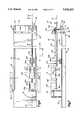
- FIG. 1is a top plan view of an apparatus for use in imaging a joint region in accordance with the method of the present invention
- FIG. 2is a side elevational view of the apparatus of FIG. 1;
- FIG. 3is a partial end view, taken along the line 3--3 of FIG. 1;
- FIG. 4is an enlarged perspective view of a portion of the apparatus of FIG. 1;
- FIG. 5is an enlarged perspective view, generally similar to FIG. 4, showing an alternate embodiment of a portion of the apparatus of FIG. 1;
- FIG. 6is a top plan view of an apparatus for use in imaging a joint region in accordance with the method of the present invention, the apparatus includes a support for use inside a primary imaging coil of a magnetic resonance imaging apparatus;
- FIG. 7is a side elevational view of the apparatus of FIG. 1;
- FIG. 8is an enlarged perspective view of a portion of an index assembly used in the apparatus of FIG. 1;
- FIG. 9is an exploded perspective view of the index assembly of FIG. 8;
- FIG. 10is a longitudinal sectional view, taken along the line 10--10 of FIG. 6, of the index assembly;
- FIG. 11is an enlarged view of a portion of FIG. 10;
- FIG. 12is a transverse sectional view taken along line 12--12 of FIG. 10;
- FIG. 13is an enlarged view of a portion of FIG. 12;
- FIG. 14is an enlarged view, similar to FIG. 11, showing the index assembly in a locked condition
- FIG. 15is an enlarged view, taken along line 15--15 of FIG. 14, showing the index assembly in a locked condition
- FIG. 16is an exploded perspective view of a free guide assembly which is part of the apparatus of FIG. 6;
- FIG. 17is an enlarged view of a portion of the free guide assembly of FIG. 16;
- FIG. 18is a perspective view of the cuff and free guide portions of the apparatus of FIG. 6;
- FIG. 19is an exploded perspective view of the cuff portion of FIG. 18;
- FIG. 20is an enlarged view of a locked pointer portion of the apparatus of FIG. 6;
- FIG. 21is an enlarged view showing the locked pointer of FIG. 20 in engagement in the index assembly.
- FIGS. 1 and 2An apparatus 500 for use in imaging a joint region where an upper portion of a limb of a patient is connected with a trunk of a patient is illustrated in FIGS. 1 and 2.
- the apparatus 500may be adapted to image either a shoulder joint region or a hip joint region of a patient.
- the apparatus 500is adapted to image a shoulder joint region of a patient.
- the apparatus 500is mounted to an imaging table 502 which may be the imaging table disclosed in U.S. patent application Ser. No. 07/802,358 filed Dec. 4, 1991 or may be a known imaging table. If desired, the patient could be supported on an apparatus other than a table.
- a known secondary imaging coil 504is secured to the table 502 by suitable means. The coil is located in a position for imaging a particular body part. As illustrated in FIGS. 1 and 2, the coil 504 is positioned to image a shoulder of a patient who is lying on the table 502 with his head adjacent the end 506 of the table 502.
- the apparatus 500includes a rotatable support rod or member 510 extending longitudinally along the table 502 from a position over the table and inside a primary coil 507 (FIG. 1) to a position off the end of the table 502 and outside the coil 507.
- the rod 510has an inner end portion 512 to which is fixed an attachment member 514.
- the member 514may be any suitable apparatus, such as a cuff, for attachment to a body part such as a forearm, for example, and may include means, such as straps 515, for securing the cuff to the body part for movement therewith.
- the rod 510also has an outward end portion 516 to which is attached a handle 518 for rotational and longitudinal movement of the rod 510 by a person other than the patient (not shown).
- the rod 510extends through and is positioned by an index mechanism 520, better seen in FIG. 4.
- the index mechanism 520includes a base 522 having a first leg portion 524 (FIG. 4) and a second leg portion 526.
- the leg portion 524is fixed to the table 502.
- the leg portion 526(FIG. 4) has an upper major side surface 528 to which are attached support blocks 530 and 532.
- the support block 530has an opening 534 through which the rod 510 extends and is movable.
- the support block 532has an opening 536, aligned with the opening 534, through which the rod 510 also extends and is movable.
- the blocks 530 and 532support the rod 510, and thus the cuff 514.
- the block 532also has a plurality of index openings 538 (FIG. 4).
- the index openings 538are spaced regularly in a circle around the rod 510.
- An index block 540is disposed on the rod 510 outside the block 532.
- the rod 510extends through an opening 546 in the index block 540.
- the index block 540includes a split clamp portion 542 and a clamping bolt 544. When the split clamp 542 is loosened, the index block 540 is rotatable on and movable longitudinally on the rod 510. When the split clamp 542 is tightened, the block 540 is fixed for movement with the rod 510.
- the index block 540has an index pin opening 550 through which is extensible an index pin 552 (FIG. 4).
- the opening 550is the same distance from the center of the opening 546, as the index openings 538 are from the center of the opening 536 in the block 532.
- the index pin opening 550is alignable with any selected one of the index openings 538 on the support block 532 by a person other than the patient.
- the index pin 552When the opening 550 is aligned with one of the index openings 538, the index pin 552 may be inserted through the index pin opening 550 and into the selected index opening 538, to block rotation of the index block 540 relative to the support block 532. If the index block 540 is clamped firmly to the rod 510, this blocks rotational movement of the rod 510 relative to the support block 532. Since the support block 532 is fixed to the table 502, this therefore blocks rotational movement of the rod 510 relative to the table 502, also thus fixing the cuff 514 in position.
- index block 541 of an index mechanism 553may have a spring loaded ball 554 on its radially outer surface facing the support block 532, which is selectively engageable at one of a plurality of ribbed index locations 556, thus functioning as a detent mechanism. This is suitable for a patient-directed operation.
- the portion of the rod 510 extending outwardly past the index mechanism 520may be omitted.
- the patientadjusts the index mechanism by moving the body part, thus moving the cuff and support rod.
- Other index constructionsare equally feasible.
- the operatorapplies force to the handle 518 (FIG. 2) to release the index ball 554 (FIG. 5) and rotate the rod 510.
- the patientis first placed on a support surface 560 (FIGS. 1 and 2) on the table 502 in a position as desired.
- the coil 504is adjusted so as to properly image the body part in question. (It should be noted that use of a secondary coil such as the coil 504 is not essential to functioning or use of the apparatus 500.)
- the cuff 514is then attached to a portion of the patient's body at a location selected to be able to move the body part to be imaged into a plurality of different positions. For example, if a shoulder joint region is to be imaged, then the cuff 514 may be attached to the patient's forearm.
- the rod 510then forms an extension of the patient's arm. Movement of the patient's forearm by means of the rod 510 and handle 518 will then cause the shoulder joint to move between a plurality of different orientations. Rotation of the patient's arm, by the patient, about the central axis of the arm is effective to rotate the cuff 514. Force applied to the cuff by the patient's arm is transmitted through the cuff to the rod 510 to rotate the rod.
- the cuff 514may be attached to the patient's leg, for example, the lower leg. Movement of the cuff 514 will cause movement of the hip joint to a plurality of different orientations in which it may be sequentially imaged. Rotation of the patient's leg, by the patient, about the central axis of the leg is effective to rotate the cuff 514. Force applied to the cuff by the patient's leg is transmitted through the cuff to the rod 510 to rotate the rod.
- the rod 510 as notedis longitudinally movable by pulling or pushing on the handle 518.
- the cuff 514thus moves longitudinally also.
- the operatorcan therefore control the longitudinal position of the cuff 514, and of its attached body part, from a location exterior to the primary coil.
- the operatorcan distract a joint of the patient.
- the operatorcan pull on the handle 518 to move the rod 510 axially toward the right (as viewed in FIGS. 1 and 2) to distract the shoulder joint of the patient.
- the operatorcan pull on the handle 518 to move the rod 510 axially toward the right (as viewed in FIGS. 1 and 2) to distract the hip joint of the patient.
- the rod 510is also rotatable, by means of the handle 518.
- the operatorrotates the handle 518 to position the cuff 514 and its attached body part in the desired orientation for imaging. This rotational position is then locked in by means of the index assembly 520.
- index assembly 520any number, location, or sequence of index locations 538 may be provided. Those shown are illustrative only. In fact, an index assembly may be provided which can be locked in any rotational position within a full circle.
- the present inventionprovides for movement of a positioning apparatus such as the cuff 514 not merely rotationally and longitudinally, but also up and down and sideways.
- the apparatus 500may be made movable up and down and also sideways relative to the table 502.
- the index blocks 530 and 532are movable up and down along rods 531 and 533 (FIG. 4), respectively, which rods are fixed to the base block 522.
- the support rod 510 (FIGS. 1 and 2) and cuff 514can be moved up and down to provide a third degree of movement in addition to the rotation and longitudinal movement available.
- the index assembly 520has a guide member 535 (FIG. 3) engaging in a slot 537.
- the index assemblyis movable sideways along the table 502 (FIGS. 1 and 2) to carry the support rod 510 and the cuff 514 in a fourth degree of movement. With these multiple degrees of movement, in multiple planes, it is now possible to move a joint into almost any position to simulate natural joint movement, while within an imaging coil.
- tractioncan be applied to a joint being imaged, in order to distract the joint.
- tractioncan be applied to a joint by pulling outwardly (to the right as viewed in FIGS. 1 and 2) on the rod 510.
- Such force when applied to the rod 510acts through the cuff 514 on the joint being imaged.
- Distracting a jointcan allow a better view of the parts of the joint and thus an increased imaging benefit. This feature is not available with present imaging apparatus.
- cuffs or clampsin addition to the one cuff shown in the drawings, may be attached to the body to more carefully and tightly control its movement and positioning.
- cuffsmay be used, such as inflatable cuffs, etc.
- the cuffsshould further be designed so that there is no plastic in contact with the skin. Such contact causes sweating and perspiration build up which causes imaging aberrations. Accordingly, a material is preferably provided against the skin to wick the perspiration away.
- the present inventionprovides an apparatus for longitudinally and rotationally positioning a body part so as to control the position or orientation of a joint connected with the body part.
- This positioningis independently controllable by the operator from a location external to the primary coil.
- This positioningrequires no physical support effort by the patient during the time period of the imaging, since the rod positioning apparatus fully supports the weight of the body part connected therewith.
- this adjustable positionerrequire any effort on the part of the patient to maintain the selected position, as the apparatus 500 performs that function also.
- a plurality of sequential imagesmay be taken of a joint, for example, in differing positions, without undue effort on the part of the patient. (It should be noted that patient control of any of the positioning apparatus of the present invention is possible, as well as the described operator control.)
- the present inventionprovides an apparatus 500 and method for use in imaging a joint region where a limb of a patient is connected with a trunk of the patient.
- the apparatus 500 and method of the present inventionmay be used to image a shoulder joint region in a chamber of the primary coil 507 of an imaging unit.
- the apparatus 500 and method of the present inventionmay also be used to image a hip joint region in the chamber of the primary coil 507.
- the cuff 514is connected with the limb of the patient, that is, either the arm or leg of the patient.
- the table 502is moved into the chamber of the primary coil 507 of a magnetic resonance imaging unit.
- the orientation of at least a portion of either the shoulder or hip joint regionis changed while the shoulder or hip joint region is in the chamber of the primary coil 507 of the magnetic resonance imaging unit.
- the orientation of a portion of the hip or shoulder joint regionis changed by rotating the cuff 514 and limb about an axis of the limb which extends through the joint region.
- the cuff and armare rotated together about the central axis of the arm and the rod 510 to change the orientation of the shoulder joint region of the patient while the shoulder joint region is in the magnetic resonance imaging unit.
- the cuff and legare rotated together about the central axis of the leg and the rod 510 to change the orientation of the hip joint region of the patient while the hip joint region is in the magnetic resonance imaging unit.
- the index mechanism 520(FIG. 4) of the index mechanism 553 (FIG. 5) is operated to an engaged condition to retain the rod in the first predetermined position.
- the index mechanism 520(FIG. 4) is operated to the engaged position by a person, other than the patient, inserting the index pin 552 into one of the index openings 538.
- the index mechanism 553is automatically operated to the engaged condition by the spring loaded ball 554 engaging an index location 556.
- the limb and the rod 510may be rotated to the first predetermined position either prior to or after movement of the joint region into the magnetic resonance imaging unit.
- the index mechanism 520 or 530is operated to a disengaged condition to release the rod 510 and cuff 514 for rotation to a next succeeding imaging position.
- the index mechanism 520is released by an operator removing the index pin 552 from an opening 538.
- the index mechanism 553is released by the patient applying force to the cuff 514 with the limb which is gripped by the cuff. This force is transmitted to the rod 510 to rotate the rod and force the spring loaded ball 554 to a retracted position.
- the index mechanism 520 or 553is re-engaged.
- the cuff 514 and rod 510are rotated.
- the cuff 514 and rod 510may be rotated under the influence of force applied against the cuff by the limb of the patient.
- the cuff 514 and rod 510may be rotated under the influence of force applied against the handle 518 by an operator.
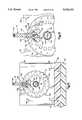
- FIG. 6illustrates an index assembly 10 for use in imaging the shoulder of a joint of a patient (not shown).
- the index assembly 10is described in detail below, as is its operation.
- the patientlies on a known support or imaging table 12 which is slidable into and out of a known primary imaging coil 14 shown schematically in FIG. 6. If desired, the patient could be supported on an apparatus other than the table 12.
- the patientWhen a table is used to support the patient, the patient lies on his back, with his head to the left and his feet to the right (as viewed in FIGS. 6 and 7).
- the patient's right handis secured in a cuff 16, with the palm facing up.
- the patient's shoulderis disposed inside a known shoulder coil 18.
- a patientrotates his hand and arm about an axis 20. The rotation of the hand and arm, and the placement of the shoulder joint in the sequential index positions spaced apart a known number of degrees are facilitated by an index mechanism 30 which is part of the overall indexing assembly 10.
- the imaging table 12is generally flat, having an upper major side or support surface 32 on which the patient lies.
- the imaging table 12has two grooves 34 and 36 (FIG. 6) in its upper major side surface 32.
- the grooves 34 and 36extend longitudinally along the table 12 for the length of the table, near the outer longitudinal edges of the table.
- the table 12has an end portion 38 near or supporting the patient's feet, to the right as viewed in FIGS. 6 and 7.
- the table end portion 38has an end surface 40 (FIG. 7) to which is attached a table extension 42.
- the table extension 42is made of two parts, an upper portion 44 and a lower portion 46, held together by suitable fasteners (not shown).
- Four screws 48extend through the table extension lower portion 46 into the table end portion 38, to secure the table extension 42 to the table 12.
- the table extension 42may alternatively be made of one part only, if feasible.
- the table extension 42has five longitudinally extending slots 50 (FIG. 9).
- the slots 50extend downward through the upper portion 44 of the table extension 42, from its upper major side surface 52 to its lower major side surface 54.
- Each slot 50has a keyhole opening 56 at its outer end.
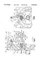
- An indexer base 60is disposed on the upper major side surface 52 of the table extension 42.
- the indexer base 60has an upper major side surface 62.
- Three keyhole openings 64extend vertically through the indexer base 60.
- a hold-down 70extends through a selected one of the keyhole openings 64 in the indexer base 60, and into one of the slots 50 in the table extension 42.
- a cross-pin 72 at the lower end of the hold-down 70is received in a widened slot portion 74 in the table extension 42.
- a fixed guide 80(FIGS. 9 and 10) is located on the upper major side surface 62 of the indexer base 60 at its inner end (to the left as viewed in FIG. 10). Two screws 82 extend up through the indexer base 60 into the fixed guide 80, to secure the fixed guide 80 to the indexer base 60.
- the fixed guide 80has a central passage 84.
- An indexer body 92(FIGS. 9 and 10) is also disposed on the upper major side surface 62 of the indexer base 60. Two screws 94 extend up through the indexer base 60 into the indexer body 92 to secure the indexer body to the indexer base.
- An index disk 100(FIGS. 8, 9 and 10) is rotatably received in the indexer body 92.
- the index disk 100has a radially outwardly extending lip 102 (FIGS. 10 and 11) engaged against a shoulder 104 (FIG. 11) on the indexer body 92.
- the engagement of the index disk lip 102 with the shoulder 104blocks axial movement of the indexer disk 100 relative to the indexer body 92, in a direction from the patient's head toward the patient's foot--i.e., to the right as viewed in FIGS. 6-10 as indicated by the arrow 106 in FIGS. 8 and 10.
- the index disk 100is circular in shape and is rotatable about the axis 20, within the indexer body 92.
- a clamp block 108(FIGS. 9 and 10) is fixed to the index disk 100 for rotation with the index disk. Two screws (not shown) extend through counterbored openings 110 (FIG. 9) in the clamp block 108 and into the index disk 100, to secure the clamp block to the index disk.
- the length of the clamp block 108is greater than the diameter of the index disk 100.
- the clamp block 108thus blocks axial movement of the index disk 100 relative to the indexer body 92, in a direction from the patient's foot toward the patient's head--i.e., to the left as viewed in FIGS. 6-10, as indicated by the arrow 112 in FIG. 10.
- a central passage 114 in the clamp block 108, and a central passage 116 in the index disk 100,are coaxial with the central passage 84 in the fixed guide 80.
- a rotatable support tube or member 120extends through the coaxial aligned openings 114, 116, and 84.
- the support tube 120is hollow and has a longitudinally extending central passage 122.
- a series of locking slots 124are formed in the support tube 120, extending through the wall of the support tube into the central opening 122.
- a lock pointer 126extends through an opening 128 (FIG. 21) in the clamp block 108, and through a selected one of the locking slots 124 in the support tube 120, and into the central passage 122 in the support tube.
- the lock pointer 126has a main body portion 130 (FIG. 20) which is rectangular in cross-sectional configuration.
- the main body portion 130has a longer dimension 132 and a shorter dimension 134.
- the longer dimension 132 of the lock pointer body portion 130is slightly shorter than the diameter of the opening 128 of the clamp block 108.
- the lock pointer 126has a handle portion 132.
- the lock pointer 126also has a lower end portion 135 separated from the main body portion by a notch 136.
- the lock pointeralso has a pointed outer end portion 138.
- the lock pointer 126is inserted through the opening 128 (FIG. 21) in the clamp block 108, in a rotational position such that the narrow dimension 134 of the lock pointer 126 fits through one of the slots 124 in the support tube 120.
- the lower end portion 135is moved radially to a location inside the tube 120.
- the lock pointer 126is then rotated so that the notch 136 engages around the wall of the support tube 120, thus locking the clamp block 108 to the support tube 120.
- the pointed outer end portion 138 of the lock pointer 126serves as an indicator to tell an MRI technician the rotational position of the support tube 120 (and of the cuff 16 which is fixed to the support tube).
- the pointed outer end portion 138 of the lock pointer 126is pointing vertically, and the clamp block 108 extends horizontally.
- the index disk 100has a set of plunger openings 140 (FIGS. 8-13) disposed in a circular array about the axis 20 (FIG. 12).
- the plunger openings 140extend axially part way into the index disk 100 (FIG. 11) in a direction as indicated by the arrow 106.
- the index disk 100also has a set of trip pins 144 (FIGS. 10-13) disposed in a circular array about the axis 20.
- the trip pins 144project axially out of the index disk 100, in a direction indicated by the arrow 112 (FIG. 10).
- a trigger base 150(FIG. 11) is disposed atop the fixed guide 80. Two screws extend down through counterbored screw holes (not shown) in the trigger base 150, into screw holes 152 (FIG. 11) in the fixed guide 80, to secure the trigger base 150 to the fixed guide 80.
- the trigger base 150supports an arbor 160 (FIG. 11).
- a screw 162secures the arbor 160 to the trigger base 150.
- the arbor 160has a main body portion 164, an intermediate portion 166, and an end portion 168.
- a trigger 170hangs down from the end portion 168 of the arbor 160 and is supported for swinging movement on the arbor 160 about an axis 172.
- a screw 174holds the trigger 170 on the arbor 160.
- the trigger 170has a lower end portion 182.
- a trigger extension 176projects axially from the trigger 170.
- the trigger extension 176includes a shank portion 178 and an outer end portion 180.
- the trigger base 150has a plunger support portion 184 with a cylindrical opening 186 which extends back into the main body of the trigger base 150.
- a main body portion 188 of a plunger 190is received in the opening 186.
- a compression spring 192biases the plunger 190 in a direction to the right, as indicated by the arrow 106.
- the plunger 190also has a reduced diameter shank portion 194, a second body portion 196, a third body portion 198, and a plunger tip portion 200.
- the third body portion 198has a radially extending end face 202 facing toward the index disk 100.
- the plunger main body portion 188 and the plunger second body portion 196define between them a longitudinally extending annular gap 204.
- a paddle 210(FIGS. 18 and 19) has a rounded end portion 212 (FIG. 19) which is press fit into an end portion 214 of the support tube 120.
- a plurality of screws 216(only one of which is shown) extend through screw holes 218 in a plastic body portion 220 of the cuff 16. The screws 216 secure the cuff 16 to the paddle 210.
- the cuff 16is bent into a semi-cylindrical shape about the axis 20.
- the cuff 16has a thumb hole 222 for receiving the right thumb of the patient's hand, and a wrist bone opening 224 to allow room for the patient's wrist bone to extend out of the cuff 16.
- the cuff 16also has a similar thumb hole 226 and wrist bone opening 228 for use when the patient's left hand is strapped in the cuff 16.
- Two straps 230extend from the one side of the plastic body portion 220 of the hand cuff 16. On the end of each strap 230 is a D-ring 232.
- a velcro strap 234extending from the opposite side of the plastic body portion 220 of the cuff 16, is extensible through the D-ring 232 to secure the patient's hand to the cuff 16. Once the cuff 16 has been secured to the patient's hand, the support tube or rod 120 forms an extension of the patient's arm.
- a free guide slider 240(FIG. 16) has a longitudinally extending rib 242 which fits into one or the other of the grooves 34, 36 in the table 12.
- the slider 240has two screw holes 244, spaced apart along the length of the slider, which receive respective screws 246 through respective slots 248 in a free guide base 250.
- the slots 240are wider than the diameter of the shank portions of the screws 246.
- the slots 246extend in a direction across the width of the table 12. Thus, when the screws 246 are inserted through the slots 248 into the slider 240, the free guide base 250 is movable across the width of the table 12 via the slots 248.
- the free guide base 250is also slidable along the length of the table 12 via the engagement of the rib 242 in the groove 34 or 36.
- Two free guide support posts 252are connected with the free guide base 250 for movement with the free guide base.
- Each post 252has a notch 254 near its lower end which receives a set screw 256. The posts 252 thus project upwardly from and are movable with the free guide base 250.
- the posts 252extend through post holes 258 in a free guide 260.
- the free guide 260has a central passage 262 for receiving therethrough the support tube 120.
- the free guide 260can move up and down on the posts 252, supporting the support tube 120 for vertical movement relative to the upper major side surface 32 of the table 12.
- the free guide 260 and the main tube 120are thus movable in all directions relative to the table 12.
- the free guide 120has a threaded opening 264 which receives the threaded shank portion 266 of a thumb screw 268.
- the head portion 270 of the thumb screw 268rides on the upper major side surface 272 of the free guide base 250. Rotation of the thumb screw 268 in the free guide 260 sets a lower limit of the vertical positioning of the free guide 260 on the free guide base 250.
- the patientlies on his back on the imaging table 12, with his head to the left and his feet to the right as viewed in FIGS. 6 and 7.
- the patient's right handis secured in the cuff 16, palm up.
- the patient's right thumbextends through the thumb hole 222 (FIG. 19).
- the wrist bonemay extend outwardly of the plastic body 220 of the cuff 16 through the wrist bone opening 224.
- the patient's shoulderis inside the shoulder coil 18 (FIG. 6), which is a known secondary imaging coil.
- the table 12is then slid axially inside the primary imaging coil 14.
- the shouldermay first be imaged in the starting orientation. Then, the patient is instructed to move the shoulder joint to the next orientation. To do this, the patient first pulls on a finger grip 280 (FIG. 8) attached to an actuator cord 282.
- the actuator cord 282is connected with the plunger 190.
- the actuator cordtransmits the force of the patient's pulling action to the plunger 190, and the plunger is retracted from the engaged position shown in FIGS. 12 and 13 to the disengaged position shown in FIGS. 10 and 11.
- the gap 204 in the plungermoves axially into a position adjacent the lower end portion 182 of the trigger 170 (FIG. 11).
- the trigger 170is then free to pivot about the axis 172.
- the force of gravitycauses the trigger 172 to assume a vertical position so that the lower end portion 182 of the trigger moves into the gap 204 in the plunger 190 (FIGS. 12, 13).
- the trigger 170then blocks axial movement of the plunger 190 toward the index disk 100.
- the plunger 190is thus held away from the index disk 100, and the index disk is free to rotate about the axis 20.
- the cuff 16Since the index disk 100 is connected through the main tube 120 with the cuff 16, the cuff 16 is now also free to rotate about the axis 20. The patient can then move his shoulder joint to the next orientation, as desired, by rotating his hand which is secured in the cuff 16.
- the patientmay grasp a handle 330 (FIGS. 6 and 7) which is secured to and forms a portion of the main tube or rotatable member 120 to better assist in rotation of the cuff 16.
- the cuff 16 and the index disk 100rotate. If the patient is turning his hand inward, the index disk 100 rotates in a clockwise direction as viewed in FIG. 12, as indicated by the arrow 290.
- the trip pins 144 and the plunger openings 140revolve about the axis 20.
- One of the trip pins designated 292 in FIG. 13almost immediately engages the trigger extension 180, and pivots the trigger out of the gap 204 in the plunger 190. This allows the plunger 190 to move back toward the index disk 100 under the influence of the plunger spring 192.
- the plunger tip 200engages the face of the index disk 100, then falls automatically into the next plunger opening 140 as the index disk 100 continues to rotate.
- the engagement of the plunger 190 in the plunger opening 140limits movement of the plunger outwardly from the trigger base 150, in a direction to the right as indicated in FIG. 11.
- a biceps support assembly 300(FIGS. 1, 2, 18 and 19), can be provided.
- the biceps support assemblyincludes a biceps cuff 302 having a plastic body portion 304 (FIG. 19).
- Two straps 306 having D-rings thereonextend from one side of the biceps cuff 302.
- Two velcro straps 308extend from the other side and can be looped through the D-rings and secured to themselves to clamp the patient's biceps firmly in the plastic body portion 304 of the biceps cuff 302.
- a plurality of fasteners 310secure the plastic body portion 304 on the biceps cuff 302 to a biceps cuff slider 312.
- the fasteners 310are received in fastener openings 314 on the upper surface of the biceps slider 312.
- the biceps slider 312has a main body portion 316 and a lower lip portion 318.
- the lip portion 318is received in a groove 320 in a paddle extension 322.
- the paddle extension 322is secured with screws 324 through openings 326 in the paddle extension 322 and through openings 328 in the paddle 210.
- the biceps cuff slider 312is slidable in the groove 320 in the paddle extension 322. Since the paddle 322 is fixed relative to the paddle 210 and the main tube 120, the biceps cuff 302 is thus slidable in a direction parallel to the axis 20, relative to the hand cuff 16. Thus, the patient's biceps can be securely clamped in the biceps cuff assembly 300, to provide additional support and stability for the arm while it is being imaged, yet the biceps cuff assembly is slidable along the length of the table to provide for adjustment and movement during changing orientation.
- the cuff 16(FIGS. 6 and 7) may be placed at different longitudinal positions along the length of the table 12 relative to the index mechanism 30.
- the main tube 120has a plurality of slots 124 adjacent the index mechanism 30.
- the lock pointer 126as discussed above, is received in a selected one of these slots 124.
- the lock pointer 126may be disengaged from the position shown in FIG. 21, and moved radially outwardly of the main tube 120 so that the main tube 120 may be slid longitudinally along the axis 20 relative to the clamp block 108.
- the lock pointer 126is inserted through the nearest slot 124 into the main tube 120, and secured therein, as described above.
- the free guide 260(FIG. 16) is relatively movable on the table 12. This movement accommodates shifting movement of the hand cuff 16 upon movement of the patient's hand or shoulder joint. For example, as the patient's hand is rotated inwardly, the arm tends to rise.
- the free guide 260allows for this movement, sliding vertically upward along the free guide support posts 252.
- the entire index mechanism 30may be placed in different lateral positions on the table extension 42.
- three keyholes 64(FIG. 9) are provided in the indexer base 60, while five slots 50 are provided in the table extension 42.
- the indexer base 60may be secured to the table extension 42 with the hold-down 70 extending through any one of the three keyholes 64 into any one of the slots 52.
- a total of fifteen different positionsare available for the indexer base 60, laterally across the width of the table extension 42. This can accommodate imaging of patients with different physical characteristics, as well as, of course, imaging of the right or the left hand.
- the free guide 260would be placed in the groove 36 (FIG. 6) on the opposite side of the table 12.
- the apparatus 10may be used in many different ways.
- the apparatusmay be used in association with the imaging table 12 as described herein.
- the apparatus 10may be used with other known patient support structures, if desired.
- the patientcould be sitting, standing, or lying when the apparatus 10 is used to image a shoulder joint of the patient.
- the cuff 16may be used with or without the biceps support assembly 300.
- the cuff 16 and the biceps support assembly 300may be eliminated and the main tube or rod 120 rotated by force transmitted from the hand of the patient to the handle 330.
- the use of the apparatus 10may be either patient directed or operator directed.
- forceis transmitted from the arm of the patient through the cuff 16 to the tube or rod 120, and/or through the biceps support assembly 300 to the tube or rod 120, and/or through the handle 330 to the tube or rod 120.
- the cuff 16, the biceps support assembly 300, and the handle 330may be used either separately or together to transmit force from the arm of the patient to the tube or rod 120.
- the patientactuates the index mechanism 30 from an engaged condition to a disengaged condition by pulling on the finger grip 280 to transmit force through the actuator cord 282.
- the tube or rod 120When the apparatus 10 is to be operator directed, the tube or rod 120 is rotated about its central axis under the influence of force applied to the handle at the right (as viewed in FIG. 7) end of the tube or rod 120 by an operator.
- the index mechanism 30may be operated from the engaged condition to the disengaged condition by force transmitted to the index mechanism by the operator.
- the patientcould use the finger grip 280 to actuate the index mechanism 30 from the engaged condition to the disengaged condition when instructed by the operator. The operator would then apply force to the handle at the end of the rod or tube 120 to rotate the rod or tube after the patient has operated the index mechanism to the disengaged condition.
- the apparatus 10has been in conjunction the imaging of an arm at a shoulder joint where the arm is connected with a trunk of the patient.
- the apparatus 10could be used in conjunction with the imaging of a hip joint where the leg of the patient is connected with the trunk of the patient.
- the operatorcould distract either the hip or shoulder joint by pulling on the handle at the right (as viewed in FIG. 7) end of the rod or tube 120 during imaging at some or all of the positions to which the index mechanism 30 is operated.
Landscapes
- Health & Medical Sciences (AREA)
- Life Sciences & Earth Sciences (AREA)
- Engineering & Computer Science (AREA)
- Physics & Mathematics (AREA)
- Medical Informatics (AREA)
- General Health & Medical Sciences (AREA)
- Nuclear Medicine, Radiotherapy & Molecular Imaging (AREA)
- Biomedical Technology (AREA)
- Animal Behavior & Ethology (AREA)
- Public Health (AREA)
- Veterinary Medicine (AREA)
- Pathology (AREA)
- Biophysics (AREA)
- Heart & Thoracic Surgery (AREA)
- Molecular Biology (AREA)
- Surgery (AREA)
- High Energy & Nuclear Physics (AREA)
- Radiology & Medical Imaging (AREA)
- Optics & Photonics (AREA)
- Signal Processing (AREA)
- Vascular Medicine (AREA)
- Condensed Matter Physics & Semiconductors (AREA)
- General Physics & Mathematics (AREA)
- Dentistry (AREA)
- Oral & Maxillofacial Surgery (AREA)
- Orthopedic Medicine & Surgery (AREA)
- Rheumatology (AREA)
- Physical Education & Sports Medicine (AREA)
- Magnetic Resonance Imaging Apparatus (AREA)
Abstract
Description
Claims (44)
Priority Applications (1)
| Application Number | Priority Date | Filing Date | Title |
|---|---|---|---|
| US08/237,598US5542423A (en) | 1991-12-04 | 1994-05-03 | Indexing assembly for joint imaging |
Applications Claiming Priority (3)
| Application Number | Priority Date | Filing Date | Title |
|---|---|---|---|
| US07/802,358US5349956A (en) | 1991-12-04 | 1991-12-04 | Apparatus and method for use in medical imaging |
| US07/950,600US5343580A (en) | 1991-12-04 | 1992-09-24 | Indexing assembly for shoulder imaging |
| US08/237,598US5542423A (en) | 1991-12-04 | 1994-05-03 | Indexing assembly for joint imaging |
Related Parent Applications (2)
| Application Number | Title | Priority Date | Filing Date |
|---|---|---|---|
| US07/802,358Continuation-In-PartUS5349956A (en) | 1991-12-04 | 1991-12-04 | Apparatus and method for use in medical imaging |
| US07/950,600Continuation-In-PartUS5343580A (en) | 1991-12-04 | 1992-09-24 | Indexing assembly for shoulder imaging |
Publications (1)
| Publication Number | Publication Date |
|---|---|
| US5542423Atrue US5542423A (en) | 1996-08-06 |
Family
ID=27122437
Family Applications (1)
| Application Number | Title | Priority Date | Filing Date |
|---|---|---|---|
| US08/237,598Expired - LifetimeUS5542423A (en) | 1991-12-04 | 1994-05-03 | Indexing assembly for joint imaging |
Country Status (1)
| Country | Link |
|---|---|
| US (1) | US5542423A (en) |
Cited By (42)
| Publication number | Priority date | Publication date | Assignee | Title |
|---|---|---|---|---|
| US5636636A (en)* | 1993-09-04 | 1997-06-10 | U.S. Philips Corporation | Magnetic resonance method for imaging a moving object and device for carrying out the method |
| US5697164A (en)* | 1994-11-18 | 1997-12-16 | Siemens Aktiengesellschaft | Movable positioning aid permitting abduction and rotation of the shoulder joint for a kinematic imaging examination thereof |
| US5704356A (en)* | 1996-05-06 | 1998-01-06 | Raycont Ltd. | System and method of diagnosis of malformed hips in babies or small animals |
| US5758647A (en)* | 1996-10-17 | 1998-06-02 | Cummins; Jimmie E. | Support and indexing apparatus for lumbar region imaging |
| US5931781A (en)* | 1996-12-18 | 1999-08-03 | U.S. Philips Corporation | MR method for the imaging of jointed movable parts |
| US20040098803A1 (en)* | 2000-06-02 | 2004-05-27 | Rolf Schindler | Positioning aid for use in performing a tomographic functional examination of the cervical spine |
| US20040133097A1 (en)* | 1991-12-04 | 2004-07-08 | Bonutti Peter M. | Apparatus and method for use in medical imaging |
| US20080086072A1 (en)* | 2006-10-04 | 2008-04-10 | Bonutti Peter M | Methods and devices for controlling biologic microenvironments |
| WO2008116203A2 (en) | 2007-03-22 | 2008-09-25 | Marctec, Llc | Methods and devices for intracorporeal bonding or interlocking of implants with thermal energy |
| WO2009029908A1 (en) | 2007-08-30 | 2009-03-05 | Marctec, Llc | Methods and devices for utilizing thermal energy to bond, stake and/or remove implants |
| US7854750B2 (en) | 2002-08-27 | 2010-12-21 | P Tech, Llc. | Apparatus and method for securing a suture |
| US7967820B2 (en) | 2006-02-07 | 2011-06-28 | P Tech, Llc. | Methods and devices for trauma welding |
| WO2012129097A1 (en)* | 2011-03-21 | 2012-09-27 | Pamichev Christo | Methods and systems for performing hip joint distraction |
| AT511693B1 (en)* | 2012-02-02 | 2013-02-15 | Menges Manfred | AUXILIARY DEVICE FOR EXAMINING A HIP JOINT |
| US8496657B2 (en) | 2006-02-07 | 2013-07-30 | P Tech, Llc. | Methods for utilizing vibratory energy to weld, stake and/or remove implants |
| US8617185B2 (en) | 2007-02-13 | 2013-12-31 | P Tech, Llc. | Fixation device |
| US20140068864A1 (en)* | 2012-09-07 | 2014-03-13 | Andrew D. Clark | Surgical Support System |
| US8747439B2 (en) | 2000-03-13 | 2014-06-10 | P Tech, Llc | Method of using ultrasonic vibration to secure body tissue with fastening element |
| US8808329B2 (en) | 1998-02-06 | 2014-08-19 | Bonutti Skeletal Innovations Llc | Apparatus and method for securing a portion of a body |
| US8814902B2 (en) | 2000-05-03 | 2014-08-26 | Bonutti Skeletal Innovations Llc | Method of securing body tissue |
| US8845699B2 (en) | 1999-08-09 | 2014-09-30 | Bonutti Skeletal Innovations Llc | Method of securing tissue |
| US8845687B2 (en) | 1996-08-19 | 2014-09-30 | Bonutti Skeletal Innovations Llc | Anchor for securing a suture |
| US8932330B2 (en) | 2000-03-13 | 2015-01-13 | P Tech, Llc | Method and device for securing body tissue |
| WO2015015851A1 (en)* | 2013-07-30 | 2015-02-05 | コニカミノルタ株式会社 | Medical image system and joint cartilage state score determination method |
| US9060767B2 (en) | 2003-04-30 | 2015-06-23 | P Tech, Llc | Tissue fastener and methods for using same |
| US9089323B2 (en) | 2005-02-22 | 2015-07-28 | P Tech, Llc | Device and method for securing body tissue |
| US9138222B2 (en) | 2000-03-13 | 2015-09-22 | P Tech, Llc | Method and device for securing body tissue |
| US9149281B2 (en) | 2002-03-20 | 2015-10-06 | P Tech, Llc | Robotic system for engaging a fastener with body tissue |
| US9173647B2 (en) | 2004-10-26 | 2015-11-03 | P Tech, Llc | Tissue fixation system |
| US9226828B2 (en) | 2004-10-26 | 2016-01-05 | P Tech, Llc | Devices and methods for stabilizing tissue and implants |
| US9271766B2 (en) | 2004-10-26 | 2016-03-01 | P Tech, Llc | Devices and methods for stabilizing tissue and implants |
| US9439642B2 (en) | 2006-02-07 | 2016-09-13 | P Tech, Llc | Methods and devices for utilizing bondable materials |
| US9463012B2 (en) | 2004-10-26 | 2016-10-11 | P Tech, Llc | Apparatus for guiding and positioning an implant |
| US9770238B2 (en) | 2001-12-03 | 2017-09-26 | P Tech, Llc | Magnetic positioning apparatus |
| US9888916B2 (en) | 2004-03-09 | 2018-02-13 | P Tech, Llc | Method and device for securing body tissue |
| US10058393B2 (en) | 2015-10-21 | 2018-08-28 | P Tech, Llc | Systems and methods for navigation and visualization |
| US10076377B2 (en) | 2013-01-05 | 2018-09-18 | P Tech, Llc | Fixation systems and methods |
| CN111643298A (en)* | 2020-07-14 | 2020-09-11 | 吉林大学 | Rehabilitation auxiliary device for nursing leg fracture patient |
| US11246638B2 (en) | 2006-05-03 | 2022-02-15 | P Tech, Llc | Methods and devices for utilizing bondable materials |
| US11253296B2 (en) | 2006-02-07 | 2022-02-22 | P Tech, Llc | Methods and devices for intracorporeal bonding of implants with thermal energy |
| US11278331B2 (en) | 2006-02-07 | 2022-03-22 | P Tech Llc | Method and devices for intracorporeal bonding of implants with thermal energy |
| US20240261166A1 (en)* | 2023-02-08 | 2024-08-08 | Surgix Medical LLC | Detachable side rail assembly for a medical procedure table |
Citations (26)
| Publication number | Priority date | Publication date | Assignee | Title |
|---|---|---|---|---|
| US1239146A (en)* | 1914-02-16 | 1917-09-04 | Victor Electric Corp | X-ray table. |
| US2801142A (en)* | 1954-11-29 | 1957-07-30 | Jesse R Adams | Limb support for operating tables |
| US2975505A (en)* | 1955-05-10 | 1961-03-21 | William Freeman J | File holder |
| US3025397A (en)* | 1959-06-11 | 1962-03-13 | Travis | Skull radiography apparatus |
| US3124328A (en)* | 1964-03-10 | kortsch | ||
| US3521876A (en)* | 1967-12-29 | 1970-07-28 | Jeffrey P Smith | Body member support for x-ray examination |
| US3528413A (en)* | 1968-01-23 | 1970-09-15 | Marion L Aydt | Limb support |
| US3766384A (en)* | 1971-04-28 | 1973-10-16 | Tower Co Inc | Surgical table |
| US4050355A (en)* | 1976-08-16 | 1977-09-27 | Kennametal Inc. | Indexing device |
| US4232681A (en)* | 1978-05-16 | 1980-11-11 | Olaf Tulaszewski | Leg positioning device for X-ray filming |
| US4256112A (en)* | 1979-02-12 | 1981-03-17 | David Kopf Instruments | Head positioner |
| US4291229A (en)* | 1979-12-10 | 1981-09-22 | Patt Kenneth W | Support and restraining device for arthographic examination of the knees |
| US4323080A (en)* | 1980-06-23 | 1982-04-06 | Melhart Albert H | Ankle stress machine |
| US4407277A (en)* | 1980-10-27 | 1983-10-04 | Ellison Arthur E | Surgical apparatus |
| US4562588A (en)* | 1981-11-20 | 1985-12-31 | Hermann Ruf | Positioning device for an extension and repositioning apparatus |
| US4616814A (en)* | 1983-07-22 | 1986-10-14 | The Hospital For Sick Children | X-ray head holder |
| US4681308A (en)* | 1985-07-16 | 1987-07-21 | Paul Rice | Diagnostic patient support apparatus |
| US4717133A (en)* | 1984-07-13 | 1988-01-05 | Unisearch Limited | Leg holding and positioning device |
| US4827496A (en)* | 1986-06-23 | 1989-05-02 | M. C. Johnson Co., Inc. | Leg and ankle holder for assisting medical and radiological professionals in X-ray examination and filming of the ankle and foot structure |
| US5001739A (en)* | 1988-06-06 | 1991-03-19 | Fischer William B | Contoured surgical table |
| US5007912A (en)* | 1990-05-30 | 1991-04-16 | Albrektsson Bjoern | Arrangement for fixing a knee-joint in defined positions and for positional control of instruments for replacing the knee-joint with a prosthesis |
| US5078140A (en)* | 1986-05-08 | 1992-01-07 | Kwoh Yik S | Imaging device - aided robotic stereotaxis system |
| US5154178A (en)* | 1990-10-09 | 1992-10-13 | Sri International | Method and apparatus for obtaining in-vivo nmr data from a moving subject |
| US5267949A (en)* | 1992-03-25 | 1993-12-07 | Manuel De La Torre | Positioning device for a lower extremity |
| US5329924A (en)* | 1991-12-04 | 1994-07-19 | Apogee Medical Products, Inc. | Sequential imaging apparatus |
| US5349956A (en)* | 1991-12-04 | 1994-09-27 | Apogee Medical Products, Inc. | Apparatus and method for use in medical imaging |
- 1994
- 1994-05-03USUS08/237,598patent/US5542423A/ennot_activeExpired - Lifetime
Patent Citations (26)
| Publication number | Priority date | Publication date | Assignee | Title |
|---|---|---|---|---|
| US3124328A (en)* | 1964-03-10 | kortsch | ||
| US1239146A (en)* | 1914-02-16 | 1917-09-04 | Victor Electric Corp | X-ray table. |
| US2801142A (en)* | 1954-11-29 | 1957-07-30 | Jesse R Adams | Limb support for operating tables |
| US2975505A (en)* | 1955-05-10 | 1961-03-21 | William Freeman J | File holder |
| US3025397A (en)* | 1959-06-11 | 1962-03-13 | Travis | Skull radiography apparatus |
| US3521876A (en)* | 1967-12-29 | 1970-07-28 | Jeffrey P Smith | Body member support for x-ray examination |
| US3528413A (en)* | 1968-01-23 | 1970-09-15 | Marion L Aydt | Limb support |
| US3766384A (en)* | 1971-04-28 | 1973-10-16 | Tower Co Inc | Surgical table |
| US4050355A (en)* | 1976-08-16 | 1977-09-27 | Kennametal Inc. | Indexing device |
| US4232681A (en)* | 1978-05-16 | 1980-11-11 | Olaf Tulaszewski | Leg positioning device for X-ray filming |
| US4256112A (en)* | 1979-02-12 | 1981-03-17 | David Kopf Instruments | Head positioner |
| US4291229A (en)* | 1979-12-10 | 1981-09-22 | Patt Kenneth W | Support and restraining device for arthographic examination of the knees |
| US4323080A (en)* | 1980-06-23 | 1982-04-06 | Melhart Albert H | Ankle stress machine |
| US4407277A (en)* | 1980-10-27 | 1983-10-04 | Ellison Arthur E | Surgical apparatus |
| US4562588A (en)* | 1981-11-20 | 1985-12-31 | Hermann Ruf | Positioning device for an extension and repositioning apparatus |
| US4616814A (en)* | 1983-07-22 | 1986-10-14 | The Hospital For Sick Children | X-ray head holder |
| US4717133A (en)* | 1984-07-13 | 1988-01-05 | Unisearch Limited | Leg holding and positioning device |
| US4681308A (en)* | 1985-07-16 | 1987-07-21 | Paul Rice | Diagnostic patient support apparatus |
| US5078140A (en)* | 1986-05-08 | 1992-01-07 | Kwoh Yik S | Imaging device - aided robotic stereotaxis system |
| US4827496A (en)* | 1986-06-23 | 1989-05-02 | M. C. Johnson Co., Inc. | Leg and ankle holder for assisting medical and radiological professionals in X-ray examination and filming of the ankle and foot structure |
| US5001739A (en)* | 1988-06-06 | 1991-03-19 | Fischer William B | Contoured surgical table |
| US5007912A (en)* | 1990-05-30 | 1991-04-16 | Albrektsson Bjoern | Arrangement for fixing a knee-joint in defined positions and for positional control of instruments for replacing the knee-joint with a prosthesis |
| US5154178A (en)* | 1990-10-09 | 1992-10-13 | Sri International | Method and apparatus for obtaining in-vivo nmr data from a moving subject |
| US5329924A (en)* | 1991-12-04 | 1994-07-19 | Apogee Medical Products, Inc. | Sequential imaging apparatus |
| US5349956A (en)* | 1991-12-04 | 1994-09-27 | Apogee Medical Products, Inc. | Apparatus and method for use in medical imaging |
| US5267949A (en)* | 1992-03-25 | 1993-12-07 | Manuel De La Torre | Positioning device for a lower extremity |
Non-Patent Citations (2)
| Title |
|---|
| "Patellofemoral joint abnormalities in athletes: Evaluation by kinematic magnetic resonance imaging" by Frank G. Shellock, PhD pp. 71-95 of Topics in Magnetic Resonance Imaging/vol. 3, Issue 4, 1991. |
| Patellofemoral joint abnormalities in athletes: Evaluation by kinematic magnetic resonance imaging by Frank G. Shellock, PhD pp. 71 95 of Topics in Magnetic Resonance Imaging/vol. 3, Issue 4, 1991.* |
Cited By (112)
| Publication number | Priority date | Publication date | Assignee | Title |
|---|---|---|---|---|
| US20040220467A1 (en)* | 1991-12-04 | 2004-11-04 | Bonutti Peter M. | Patient support apparatus |
| US7328055B2 (en) | 1991-12-04 | 2008-02-05 | Marctec, Llc | Patient support apparatus |
| US6882877B2 (en) | 1991-12-04 | 2005-04-19 | Bonutti Research, Inc. | Magnetic resonance imaging system and method |
| US20040133097A1 (en)* | 1991-12-04 | 2004-07-08 | Bonutti Peter M. | Apparatus and method for use in medical imaging |
| US5636636A (en)* | 1993-09-04 | 1997-06-10 | U.S. Philips Corporation | Magnetic resonance method for imaging a moving object and device for carrying out the method |
| US5697164A (en)* | 1994-11-18 | 1997-12-16 | Siemens Aktiengesellschaft | Movable positioning aid permitting abduction and rotation of the shoulder joint for a kinematic imaging examination thereof |
| US5704356A (en)* | 1996-05-06 | 1998-01-06 | Raycont Ltd. | System and method of diagnosis of malformed hips in babies or small animals |
| US8845687B2 (en) | 1996-08-19 | 2014-09-30 | Bonutti Skeletal Innovations Llc | Anchor for securing a suture |
| US5758647A (en)* | 1996-10-17 | 1998-06-02 | Cummins; Jimmie E. | Support and indexing apparatus for lumbar region imaging |
| US5931781A (en)* | 1996-12-18 | 1999-08-03 | U.S. Philips Corporation | MR method for the imaging of jointed movable parts |
| US8808329B2 (en) | 1998-02-06 | 2014-08-19 | Bonutti Skeletal Innovations Llc | Apparatus and method for securing a portion of a body |
| US8845699B2 (en) | 1999-08-09 | 2014-09-30 | Bonutti Skeletal Innovations Llc | Method of securing tissue |
| US9138222B2 (en) | 2000-03-13 | 2015-09-22 | P Tech, Llc | Method and device for securing body tissue |
| US9067362B2 (en) | 2000-03-13 | 2015-06-30 | P Tech, Llc | Method of using ultrasonic vibration to secure body tissue with fastening element |
| US8932330B2 (en) | 2000-03-13 | 2015-01-13 | P Tech, Llc | Method and device for securing body tissue |
| US9986994B2 (en) | 2000-03-13 | 2018-06-05 | P Tech, Llc | Method and device for securing body tissue |
| US9884451B2 (en) | 2000-03-13 | 2018-02-06 | P Tech, Llc | Method of using ultrasonic vibration to secure body tissue |
| US8747439B2 (en) | 2000-03-13 | 2014-06-10 | P Tech, Llc | Method of using ultrasonic vibration to secure body tissue with fastening element |
| US8814902B2 (en) | 2000-05-03 | 2014-08-26 | Bonutti Skeletal Innovations Llc | Method of securing body tissue |
| US7243387B2 (en)* | 2000-06-02 | 2007-07-17 | Rolf Schindler | Positioning aid for use in performing a tomographic functional examination of the cervical spine |
| US20040098803A1 (en)* | 2000-06-02 | 2004-05-27 | Rolf Schindler | Positioning aid for use in performing a tomographic functional examination of the cervical spine |
| US9770238B2 (en) | 2001-12-03 | 2017-09-26 | P Tech, Llc | Magnetic positioning apparatus |
| US9629687B2 (en) | 2002-03-20 | 2017-04-25 | P Tech, Llc | Robotic arthroplasty system |
| US10869728B2 (en) | 2002-03-20 | 2020-12-22 | P Tech, Llc | Robotic surgery |
| US10265128B2 (en) | 2002-03-20 | 2019-04-23 | P Tech, Llc | Methods of using a robotic spine system |
| US10932869B2 (en) | 2002-03-20 | 2021-03-02 | P Tech, Llc | Robotic surgery |
| US10959791B2 (en) | 2002-03-20 | 2021-03-30 | P Tech, Llc | Robotic surgery |
| US9877793B2 (en) | 2002-03-20 | 2018-01-30 | P Tech, Llc | Robotic arthroplasty system |
| US9585725B2 (en) | 2002-03-20 | 2017-03-07 | P Tech, Llc | Robotic arthroplasty system |
| US10368953B2 (en) | 2002-03-20 | 2019-08-06 | P Tech, Llc | Robotic system for fastening layers of body tissue together and method thereof |
| US9808318B2 (en) | 2002-03-20 | 2017-11-07 | P Tech, Llc | Robotic arthroplasty system |
| US9271779B2 (en) | 2002-03-20 | 2016-03-01 | P Tech, Llc | Methods of using a robotic spine system |
| US9271741B2 (en) | 2002-03-20 | 2016-03-01 | P Tech, Llc | Robotic ultrasonic energy system |
| US9155544B2 (en) | 2002-03-20 | 2015-10-13 | P Tech, Llc | Robotic systems and methods |
| US9192395B2 (en) | 2002-03-20 | 2015-11-24 | P Tech, Llc | Robotic fastening system |
| US9486227B2 (en) | 2002-03-20 | 2016-11-08 | P Tech, Llc | Robotic retractor system |
| US9149281B2 (en) | 2002-03-20 | 2015-10-06 | P Tech, Llc | Robotic system for engaging a fastener with body tissue |
| US8162977B2 (en) | 2002-08-27 | 2012-04-24 | P Tech, Llc. | Method for joining implants |
| US9750496B2 (en) | 2002-08-27 | 2017-09-05 | P Tech, Llc | System for securing a portion of a body |
| US7854750B2 (en) | 2002-08-27 | 2010-12-21 | P Tech, Llc. | Apparatus and method for securing a suture |
| US9962162B2 (en) | 2003-04-30 | 2018-05-08 | P Tech, Llc | Tissue fastener and methods for using same |
| US9060767B2 (en) | 2003-04-30 | 2015-06-23 | P Tech, Llc | Tissue fastener and methods for using same |
| US9888916B2 (en) | 2004-03-09 | 2018-02-13 | P Tech, Llc | Method and device for securing body tissue |
| US9271766B2 (en) | 2004-10-26 | 2016-03-01 | P Tech, Llc | Devices and methods for stabilizing tissue and implants |
| US9579129B2 (en) | 2004-10-26 | 2017-02-28 | P Tech, Llc | Devices and methods for stabilizing tissue and implants |
| US9867706B2 (en) | 2004-10-26 | 2018-01-16 | P Tech, Llc | Tissue fastening system |
| US9980761B2 (en) | 2004-10-26 | 2018-05-29 | P Tech, Llc | Tissue fixation system and method |
| US9814453B2 (en) | 2004-10-26 | 2017-11-14 | P Tech, Llc | Deformable fastener system |
| US9463012B2 (en) | 2004-10-26 | 2016-10-11 | P Tech, Llc | Apparatus for guiding and positioning an implant |
| US10238378B2 (en) | 2004-10-26 | 2019-03-26 | P Tech, Llc | Tissue fixation system and method |
| US11992205B2 (en) | 2004-10-26 | 2024-05-28 | P Tech, Llc | Devices and methods for stabilizing tissue and implants |
| US9545268B2 (en) | 2004-10-26 | 2017-01-17 | P Tech, Llc | Devices and methods for stabilizing tissue and implants |
| US9999449B2 (en) | 2004-10-26 | 2018-06-19 | P Tech, Llc | Devices and methods for stabilizing tissue and implants |
| US10813764B2 (en) | 2004-10-26 | 2020-10-27 | P Tech, Llc | Expandable introducer system and methods |
| US9226828B2 (en) | 2004-10-26 | 2016-01-05 | P Tech, Llc | Devices and methods for stabilizing tissue and implants |
| US11013542B2 (en) | 2004-10-26 | 2021-05-25 | P Tech, Llc | Tissue fixation system and method |
| US11457958B2 (en) | 2004-10-26 | 2022-10-04 | P Tech, Llc | Devices and methods for stabilizing tissue and implants |
| US9173647B2 (en) | 2004-10-26 | 2015-11-03 | P Tech, Llc | Tissue fixation system |
| US9089323B2 (en) | 2005-02-22 | 2015-07-28 | P Tech, Llc | Device and method for securing body tissue |
| US9980717B2 (en) | 2005-02-22 | 2018-05-29 | P Tech, Llc | Device and method for securing body tissue |
| US11219446B2 (en) | 2005-10-05 | 2022-01-11 | P Tech, Llc | Deformable fastener system |
| US10441269B1 (en) | 2005-10-05 | 2019-10-15 | P Tech, Llc | Deformable fastener system |
| US10376259B2 (en) | 2005-10-05 | 2019-08-13 | P Tech, Llc | Deformable fastener system |
| US9743963B2 (en) | 2006-02-07 | 2017-08-29 | P Tech, Llc | Methods and devices for trauma welding |
| US10368924B2 (en) | 2006-02-07 | 2019-08-06 | P Tech, Llc | Methods and devices for trauma welding |
| US9610073B2 (en) | 2006-02-07 | 2017-04-04 | P Tech, Llc | Methods and devices for intracorporeal bonding of implants with thermal energy |
| US11129645B2 (en) | 2006-02-07 | 2021-09-28 | P Tech, Llc | Methods of securing a fastener |
| US9439642B2 (en) | 2006-02-07 | 2016-09-13 | P Tech, Llc | Methods and devices for utilizing bondable materials |
| US9421005B2 (en) | 2006-02-07 | 2016-08-23 | P Tech, Llc | Methods and devices for intracorporeal bonding of implants with thermal energy |
| US11134995B2 (en) | 2006-02-07 | 2021-10-05 | P Tech, Llc | Method and devices for intracorporeal bonding of implants with thermal energy |
| US9173650B2 (en) | 2006-02-07 | 2015-11-03 | P Tech, Llc | Methods and devices for trauma welding |
| US8496657B2 (en) | 2006-02-07 | 2013-07-30 | P Tech, Llc. | Methods for utilizing vibratory energy to weld, stake and/or remove implants |
| US11253296B2 (en) | 2006-02-07 | 2022-02-22 | P Tech, Llc | Methods and devices for intracorporeal bonding of implants with thermal energy |
| US11278331B2 (en) | 2006-02-07 | 2022-03-22 | P Tech Llc | Method and devices for intracorporeal bonding of implants with thermal energy |
| US11998251B2 (en) | 2006-02-07 | 2024-06-04 | P Tech, Llc | Methods and devices for intracorporeal bonding of implants with thermal energy |
| US7967820B2 (en) | 2006-02-07 | 2011-06-28 | P Tech, Llc. | Methods and devices for trauma welding |
| US12232789B2 (en) | 2006-05-03 | 2025-02-25 | P Tech, Llc | Methods and devices for utilizing bondable materials |
| US11246638B2 (en) | 2006-05-03 | 2022-02-15 | P Tech, Llc | Methods and devices for utilizing bondable materials |
| US12402927B2 (en) | 2006-05-03 | 2025-09-02 | P Tech, Llc | Methods and devices for utilizing bondable materials |
| US8641660B2 (en) | 2006-10-04 | 2014-02-04 | P Tech, Llc | Methods and devices for controlling biologic microenvironments |
| US9474847B2 (en) | 2006-10-04 | 2016-10-25 | P Tech, Llc | Methods and devices for controlling biologic microenvironments |
| US20080086072A1 (en)* | 2006-10-04 | 2008-04-10 | Bonutti Peter M | Methods and devices for controlling biologic microenvironments |
| US10390817B2 (en) | 2007-02-13 | 2019-08-27 | P Tech, Llc | Tissue fixation system and method |
| US12137898B2 (en) | 2007-02-13 | 2024-11-12 | P Tech, Llc | Tissue fixation system and method |
| US10517584B1 (en) | 2007-02-13 | 2019-12-31 | P Tech, Llc | Tissue fixation system and method |
| US11801044B2 (en) | 2007-02-13 | 2023-10-31 | P Tech, Llc | Tissue fixation system and method |
| US9402668B2 (en) | 2007-02-13 | 2016-08-02 | P Tech, Llc | Tissue fixation system and method |
| US8617185B2 (en) | 2007-02-13 | 2013-12-31 | P Tech, Llc. | Fixation device |
| WO2008116203A2 (en) | 2007-03-22 | 2008-09-25 | Marctec, Llc | Methods and devices for intracorporeal bonding or interlocking of implants with thermal energy |
| WO2009029908A1 (en) | 2007-08-30 | 2009-03-05 | Marctec, Llc | Methods and devices for utilizing thermal energy to bond, stake and/or remove implants |
| WO2012129097A1 (en)* | 2011-03-21 | 2012-09-27 | Pamichev Christo | Methods and systems for performing hip joint distraction |
| EP2623029A1 (en)* | 2012-02-02 | 2013-08-07 | Manfred Menges | Auxiliary device for examining a hip joint |
| AT511693B1 (en)* | 2012-02-02 | 2013-02-15 | Menges Manfred | AUXILIARY DEVICE FOR EXAMINING A HIP JOINT |
| AT511693A4 (en)* | 2012-02-02 | 2013-02-15 | Menges Manfred | AUXILIARY DEVICE FOR EXAMINING A HIP JOINT |
| US9730851B2 (en)* | 2012-09-07 | 2017-08-15 | Allen Medical Systems, Inc. | Surgical support system |
| US10702437B2 (en) | 2012-09-07 | 2020-07-07 | Allen Medical Systems, Inc. | Surgical support system |
| US20140068864A1 (en)* | 2012-09-07 | 2014-03-13 | Andrew D. Clark | Surgical Support System |
| US10076377B2 (en) | 2013-01-05 | 2018-09-18 | P Tech, Llc | Fixation systems and methods |
| US10085701B2 (en) | 2013-07-30 | 2018-10-02 | Konica Minolta, Inc. | Medical image system and joint cartilage state score determination method |
| WO2015015851A1 (en)* | 2013-07-30 | 2015-02-05 | コニカミノルタ株式会社 | Medical image system and joint cartilage state score determination method |
| US10765484B2 (en) | 2015-10-21 | 2020-09-08 | P Tech, Llc | Systems and methods for navigation and visualization |
| US11744651B2 (en) | 2015-10-21 | 2023-09-05 | P Tech, Llc | Systems and methods for navigation and visualization |
| US11684430B2 (en) | 2015-10-21 | 2023-06-27 | P Tech, Llc | Systems and methods for navigation and visualization |
| US11317974B2 (en) | 2015-10-21 | 2022-05-03 | P Tech, Llc | Systems and methods for navigation and visualization |
| US12023111B2 (en) | 2015-10-21 | 2024-07-02 | P Tech, Llc | Systems and methods for navigation and visualization |
| US12096995B2 (en) | 2015-10-21 | 2024-09-24 | P Tech, Llc | Systems and methods for navigation and visualization |
| US12268455B2 (en) | 2015-10-21 | 2025-04-08 | P Tech, Llc | Systems and methods for navigation and visualization |
| US10058393B2 (en) | 2015-10-21 | 2018-08-28 | P Tech, Llc | Systems and methods for navigation and visualization |
| CN111643298B (en)* | 2020-07-14 | 2021-04-30 | 吉林大学 | A kind of rehabilitation therapy auxiliary device for nursing of patients with leg fracture |
| CN111643298A (en)* | 2020-07-14 | 2020-09-11 | 吉林大学 | Rehabilitation auxiliary device for nursing leg fracture patient |
| US20240261166A1 (en)* | 2023-02-08 | 2024-08-08 | Surgix Medical LLC | Detachable side rail assembly for a medical procedure table |
| US12370109B2 (en)* | 2023-02-08 | 2025-07-29 | Surgix Medical LLC | Detachable side rail assembly for a medical procedure table |
Similar Documents
| Publication | Publication Date | Title |
|---|---|---|
| US5542423A (en) | Indexing assembly for joint imaging | |
| US6141579A (en) | Sequential imaging apparatus | |
| US5329924A (en) | Sequential imaging apparatus | |
| US5349956A (en) | Apparatus and method for use in medical imaging | |
| US6697659B1 (en) | Method of imaging a joint in a body of patient | |
| US6629944B2 (en) | Limb-positioning and traction device | |
| US5608934A (en) | Hip distractor | |
| US7771378B2 (en) | Orthopedic traction tower system | |
| US8425404B2 (en) | System and method for positioning a laparoscopic device | |
| US5462551A (en) | Knee positioner | |
| CA1271102A (en) | Patient limb positioning apparatus | |
| US5372558A (en) | Exercise device | |
| US5643159A (en) | Therapeutic exercise device | |
| US6467487B1 (en) | Holding device for wrist/shoulder arthroscopy and surgery | |
| US10893995B2 (en) | Lift for extremity surgical positioning device | |
| US9205016B2 (en) | Therapy apparatus to restore range of motion of limbs | |
| US5881730A (en) | Surgical hand support apparatus | |
| US20100229874A1 (en) | Method and Apparatus for Multidirectional Positioning of a Shoulder | |
| US20080081748A1 (en) | Exercise equipment adapted for use with a chair | |
| US5343580A (en) | Indexing assembly for shoulder imaging | |
| US6626408B1 (en) | Adjustable limb support | |
| JP7237174B2 (en) | Hip or knee surgical leg retainer and method of placement | |
| EP3484361A1 (en) | Device for the examination of limb joints | |
| US20060161086A1 (en) | Traction device | |
| US7621883B2 (en) | Slide lock |
Legal Events
| Date | Code | Title | Description |
|---|---|---|---|
| AS | Assignment | Owner name:BONUTTI, PETER M., M.D., ILLINOIS Free format text:ASSIGNMENT OF ASSIGNORS INTEREST;ASSIGNOR:BONUTTI, PETER M.;REEL/FRAME:007061/0423 Effective date:19940708 | |
| STCF | Information on status: patent grant | Free format text:PATENTED CASE | |
| FEPP | Fee payment procedure | Free format text:PAT HLDR NO LONGER CLAIMS SMALL ENT STAT AS SMALL BUSINESS (ORIGINAL EVENT CODE: LSM2); ENTITY STATUS OF PATENT OWNER: LARGE ENTITY | |
| FPAY | Fee payment | Year of fee payment:4 | |
| FEPP | Fee payment procedure | Free format text:PAT HOLDER CLAIMS SMALL ENTITY STATUS, ENTITY STATUS SET TO SMALL (ORIGINAL EVENT CODE: LTOS); ENTITY STATUS OF PATENT OWNER: LARGE ENTITY | |
| FEPP | Fee payment procedure | Free format text:PAT HOLDER NO LONGER CLAIMS SMALL ENTITY STATUS, ENTITY STATUS SET TO UNDISCOUNTED (ORIGINAL EVENT CODE: STOL); ENTITY STATUS OF PATENT OWNER: LARGE ENTITY | |
| FEPP | Fee payment procedure | Free format text:PAT HOLDER CLAIMS SMALL ENTITY STATUS, ENTITY STATUS SET TO SMALL (ORIGINAL EVENT CODE: LTOS); ENTITY STATUS OF PATENT OWNER: LARGE ENTITY | |
| FPAY | Fee payment | Year of fee payment:8 | |
| FEPP | Fee payment procedure | Free format text:PAT HOLDER NO LONGER CLAIMS SMALL ENTITY STATUS, ENTITY STATUS SET TO UNDISCOUNTED (ORIGINAL EVENT CODE: STOL); ENTITY STATUS OF PATENT OWNER: LARGE ENTITY | |
| FPAY | Fee payment | Year of fee payment:12 | |
| AS | Assignment | Owner name:BONUTTI RESEARCH, INC, ILLINOIS Free format text:ASSIGNMENT OF ASSIGNORS INTEREST;ASSIGNOR:BONUTTI, PETER M, M.D.;REEL/FRAME:028336/0567 Effective date:20120606 | |
| AS | Assignment | Owner name:ACACIA RESEARCH GROUP LLC, TEXAS Free format text:ASSIGNMENT OF ASSIGNORS INTEREST;ASSIGNOR:BONUTTI RESEARCH, INC.;REEL/FRAME:028929/0982 Effective date:20120608 | |
| AS | Assignment | Owner name:ADVANCED SKELETAL INNOVATIONS LLC, TEXAS Free format text:ASSIGNMENT OF ASSIGNORS INTEREST;ASSIGNOR:ACACIA RESEARCH GROUP LLC;REEL/FRAME:028948/0803 Effective date:20120830 | |
| AS | Assignment | Owner name:BONUTTI SKELETAL INNOVATIONS LLC, TEXAS Free format text:ASSIGNMENT OF ASSIGNORS INTEREST;ASSIGNOR:ADVANCED SKELETAL INNOVATIONS LLC;REEL/FRAME:028959/0109 Effective date:20120831 |