US5542130A - Protective goggle and lens with adjustable ventilation - Google Patents
Protective goggle and lens with adjustable ventilationDownload PDFInfo
- Publication number
- US5542130A US5542130AUS08/330,897US33089794AUS5542130AUS 5542130 AUS5542130 AUS 5542130AUS 33089794 AUS33089794 AUS 33089794AUS 5542130 AUS5542130 AUS 5542130A
- Authority
- US
- United States
- Prior art keywords
- lens
- ventilation
- shutter
- apertures
- goggle
- Prior art date
- Legal status (The legal status is an assumption and is not a legal conclusion. Google has not performed a legal analysis and makes no representation as to the accuracy of the status listed.)
- Expired - Lifetime
Links
Images


Classifications
- G—PHYSICS
- G02—OPTICS
- G02C—SPECTACLES; SUNGLASSES OR GOGGLES INSOFAR AS THEY HAVE THE SAME FEATURES AS SPECTACLES; CONTACT LENSES
- G02C11/00—Non-optical adjuncts; Attachment thereof
- G02C11/08—Anti-misting means, e.g. ventilating, heating; Wipers
- A—HUMAN NECESSITIES
- A61—MEDICAL OR VETERINARY SCIENCE; HYGIENE
- A61F—FILTERS IMPLANTABLE INTO BLOOD VESSELS; PROSTHESES; DEVICES PROVIDING PATENCY TO, OR PREVENTING COLLAPSING OF, TUBULAR STRUCTURES OF THE BODY, e.g. STENTS; ORTHOPAEDIC, NURSING OR CONTRACEPTIVE DEVICES; FOMENTATION; TREATMENT OR PROTECTION OF EYES OR EARS; BANDAGES, DRESSINGS OR ABSORBENT PADS; FIRST-AID KITS
- A61F9/00—Methods or devices for treatment of the eyes; Devices for putting in contact-lenses; Devices to correct squinting; Apparatus to guide the blind; Protective devices for the eyes, carried on the body or in the hand
- A61F9/02—Goggles
- A61F9/028—Ventilation means
Definitions
- This inventionrelates generally to protective goggles having adjustable ventilation. More particularly, this invention relates to goggles which have a flexible lens housing and are particularly well-suited for use in skiing and other outdoor sports.
- Such goggleshaving a flexible housing in which a lens is mounted are well-known. Such goggles often use a thermal lens which includes two lenses spaced in parallel relation, such as by a closed cell foam spacer, to form an air-tight chamber between the two lenses for providing thermal insulation. Such goggles are commonly used by skiers and motorcyclists to protect their eyes from wind, precipitation and debris. They may also be used by surgeons and other medical personnel during operations and the like to protect eyes from fluids such as blood. The major drawback of conventional goggles is that condensation has a tendency to form on the inside of the lens thus fogging the lens and blocking the user's vision.
- ski goggleshave been provided with ventilating apertures which overcome the drawback of fogging, but which may, under some circumstances, allow excessive ventilation.
- This excessive ventilationresults in a stream of cold air which may be unpleasant to the user, especially in extremely cold weather.
- excessive ventilationcan dry or otherwise damage sensitive tissue in and around the eyes.
- pivotable automatic flapsfor closing an air passage opening when the user reaches a certain minimum speed.
- such devicesare not practical, can be subject to icing of the closure mechanism, and are not manually adjustable by the user.
- a ventilation system for flexible goggleswould be inexpensive to manufacture, manually adjustable and easy to operate. Ease of use is particularly important because users may often be wearing gloves or mittens which reduce their dexterity.
- the goggleincludes a frame in which a lens is mounted.
- the lenshas one or more ventilation apertures.
- a ventilation adjustment assemblyis mounted on the lens to regulate air flow through the ventilation aperture.
- the ventilation adjustment assemblyuses a shutter or other suitable obstructing member which is movably disposed on the surface of the lens for being continuously positioned in and out of alignment with the lens' ventilation apertures.
- the lenshas one or more ventilation apertures forming a linear or curved path.
- An elongated shutter housingis formed by a base having a pair of parallel sidewalls or spacers mounted on the lens on opposite sides of and in close proximity to the path of lens apertures. One or more apertures on the base align with the lens apertures.
- An elongated shutteris slidably disposed in the shutter housing. The shutter has one or more apertures which are alignable with apertures in the base and lens by sliding the shutter within its housing, ventilation air flow is regulated as the shutter apertures move in and out of alignment with the base and lens apertures. A strip of permeable foam is placed over the lens ventilation apertures to baffle ventilation air flow.
- the present inventionprovides an adjustable ventilation system which can be inexpensively manufactured from just two plastic parts (the shutter and the shutter housing).
- the shutter and the shutter housingIn the embodiments disclosed herein, a simple sliding motion of the shutter allows easy manual adjustment of ventilation airflow over a continuous range. This feature makes the invention particularly useful in outdoor sports such as skiing.
- the inventionmay be embodied on a lens by itself. This allows the lens assembly which includes the manually adjustable ventilation system to be sold separately and as a replacement part for conventional goggles. Thus, a user can convert a standard goggle with a replaceable single or thermal lens into a goggle system having manually adjustable ventilation by purchases of the lens assembly alone and replacement of the original lens.
- FIG. 1is a perspective view of a goggle in accordance with the invention
- FIG. 2is an exploded perspective view of the goggle shown in FIG. 1;
- FIG. 3is a front elevation view of the shutter housing shown in FIG. 2;
- FIG. 4is a top plan view of the elongated apertured shutter shown in FIG. 2;
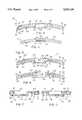
- FIG. 5is a diagram showing the ventilation adjustment assembly shown in FIG. 1 with the shutter in a fully closed position
- FIG. 6is a diagram showing the ventilation adjustment assembly shown in FIG. 1 with the shutter in a fully opened position
- FIG. 7is a sectional view of the ventilation adjustment assembly taken along lines 7--7 in FIG. 5;
- FIG. 8is a sectional view of the ventilation adjustment assembly taken along lines 8--8 in FIG. 6;
- FIG. 9is a partial exploded view of a goggle in accordance with a second embodiment of the invention.
- FIG. 1is a perspective view of a goggle 10 in accordance with the invention.
- Goggle 10generally comprises a frame 12, a lens structure 14 which is mounted in the frame 12, and a ventilation adjustment assembly 16 which is mounted on the lens structure 14.
- Goggle frame 12may have a generally annular structure and may be molded of one piece from a resilient flexible material such as a soft plastic or soft rubber. A face contacting flange or rim 18 is lined with a padding or cushion 20 of sponge-type material to seal frame 12 against the user's face (not illustrated).
- Lens structure 14 of flexible transparent material(which may be colored if desired) has a peripheral edge 22 which is received within a peripheral groove 24 formed interiorly around a front section 26 of frame 12. Lens structure 14 may be flat and bent to an arcuate configuration which fits frame 12, or may be curved and could, if desired, form a part of the structural support to maintain the shape of goggle 10.
- an elastic headband or strap 28has folded, stitched ends which are received in slots 30 formed in frame front section 26.
- a slide buckle(not illustrated) allows adjustment of the length of elastic strap 28.
- Goggle 10is shaped to fit flush against the contours of the human face. Consequently, when worn by a user, a generally closed chamber 32 is located between lens structure 14 and the user's face (not illustrated). The user's body heat and evaporating perspiration cause moisture to condense inside chamber 32. Some of this condensation collects on the inside surface of lens structure 14 fogging lens structure 14 and thereby reducing the user's vision.
- goggle frame 12may have a plurality of large vent openings 34 formed by ribs 36 which join the rim 18 to the front section 26.
- the ribs 36define with the rim 18 and front section 26 a channel 38 for a fibrous or open cell foam lining 40 which covers the openings 34 to allow a slow exchange of air between the goggle exterior and the closed chamber 32. While lining 40 is moisture and air permeable, it blocks snow and the like from entering chamber 32.
- Vent apertures covered by a fibrous stripmay be utilized in place of the illustrated vent apertures covered by a fibrous strip. While helpful, the ventilation provided by such systems is typically either insufficient to prevent fogging of lens structure 14 or so great as to cause the user discomfort.
- the goggle structure described above(excluding ventilation adjustment assembly 16) is well-known, and various modifications may be made thereto as desired.
- lens structure 14is illustrated in greater detail.
- the lens structure 14is a so-called thermal lens, although the invention may be implemented with a single lens or other types of lenses.
- Lens structure 14is formed of an inner lens 42 and an outer lens 44, both stamped from a generally planar sheet of transparent, semirigid plastic, the sheet being of uniform thickness.
- lenses 42 and 44are horizontally elongated and intermediate their ends each is provided with a downwardly opening recess 46 to accommodate the nose of a wearer.
- Lenses 42 and 44are assembled and spaced in parallel relation by an interconnecting spacer 48.
- Interconnecting spacer 48is made of closed cell, flexible foam which is bonded to lenses 42 and 44 in any suitable fashion so as to seal against both.
- Interconnecting spacer 48is located in close proximity to peripheral edges 50 and 52 of lenses 42 and 44, respectively, and extends peripherally thereabout to define a central viewing area 54. Because interconnecting spacer 48 seals against both lenses 42 and 44, a space or chamber 56 between such lenses and central viewing area 54 is sealed to provide the thermal lens. It will be observed that lenses 42 and 44 can be integrally joined to define sealed space 56 between and inner and outer lens surfaces.
- Lens structure 14is deformed from the plane of the plastic sheets making up lenses 42 and 44 into a simple curve, as opposed to a compound curve. That is, for all horizontal sections taken through lens structure 14 at any point thereon, the curve will have essentially the same profile. Stated another way, the lens is curved only about its minor dimension and not about both minor and major dimensions.
- Outer lens 44is of a size and shape suitable for mounting lens structure 14 in front section 26.
- a plurality of keyholes 58 along periphery 52 of outer lens 44engage corresponding fingers (not illustrated) in peripheral grove 24 of frame front section 26 to releasably secure outer lens 44 therein.
- outer lens 44also has a plurality of evenly spaced apertures 60 for ventilating chamber 32.
- Apertures 60may be of uniform size, spacing and circular shape and the distance between each of apertures 60 exceeds their individual width or diameter. The invention may also be practiced using apertures of irregular size, shape and spacing, or using only a single aperture. Apertures 60 are generally in linear alignment, although they may define a path that is somewhat curved about an axis running perpendicular to the plane of outer lens 44. Apertures 60 are arranged in a horizontal orientation near top edge 62 of outer lens 44. Apertures 60 need not be provided near the middle portion of outer lens 44.
- Foam spacer 48 and inner lens 42are somewhat shorter than outer lens 44, so that apertures 60 are outside the area encircled by foam spacer 48 and are, therefore, not obstructed by inner lens 42. It will be observed that this construction permits the use of ventilation apertures in a thermal lens without puncturing sealed space 56.
- An elongated tab 64also constructed of closed cell foam extends upwardly from spacer 48 and is mounted to the region of outer lens 44 containing the plurality of apertures 60. Two slotted apertures 66 in elongated tab 64 are positioned behind apertures 60 to permit the movement of ventilation air therethrough.
- Open cell foam filter 68is horizontally orientated and is mounted on and in alignment with tab 64.
- Open cell foam filter 68serves to filter air streaming through ventilation apertures 60 and slotted apertures 66, thereby preventing the intrusion into chamber 32 of particles or droplets of precipitation such as rain or snow, for example.
- Open cell foam filter 68also serves to baffle ventilation air flow having an otherwise excessive velocity.
- Ventilation adjustment assembly 16is located over the plurality of apertures 60 on outer lens 44 to regulate the flow of air therethrough. It will be noted that ventilation adjustment assembly 16 is mounted near the periphery of central viewing area 54 so as to minimize interference with the user's vision. Ventilation adjustment assembly 16 comprises a three-sided shutter housing or slide 70 in which an elongated shutter 72 is slidably disposed. As discussed below in greater detail, shutter housing 70 is mounted on lens 44 over apertures 60 to create a channel thereover. A thin, elongated apertured shutter 72 or other suitable obstruction member is slidably disposed in this channel, and various positions of the shutter 72 allow more or less ventilating air to pass through lens apertures 60. Shutter housing 70 and shutter 72 may be slightly arcuate to accommodate the curvatures of lens 44 and the path of alignment of apertures 60.
- the shutter housing 70has a three-sided cross-section formed by a pair of thin, parallel spacers or sidewalls 76 and 78 mounted on lens 44 and a relatively wider cover 80 which is mounted onto the sidewalls 76 and 78.
- Sidewalls 76 and 78are positioned on opposite sides of the line of apertures 60 in lens 44.
- Lens 44, sidewalls 76 and 78, and cover 80define a channel or track 82 extending over the apertures 60 along the width of outer lens 44.
- Flanges 84 and 86are attached to opposite longitudinal ends 88 and 90, respectively, of shutter housing cover 80 for mounting cover 80 to the lens 44.
- Index posts or fingers 92 and 94extend outwardly from flanges 84 and 86, respectively, and are received by index apertures 97 and 98 in lens 44. Sidewalls 76 and 78 and flanges 84 and 86 are mounted to lens 44 by solvent bonding.
- Shutter housing cover 80has a plurality of apertures 100 of substantially the same number, size and spacing as the apertures on lens 44.
- Shutter housing 70is mounted so that apertures 100 on cover 80 are substantially in alignment with apertures 60 on lens 44.
- Apertures 100may have an oval shape with their respective elongated axes generally perpendicular to the elongated length of shutter housing 70.
- Goggle 10could be constructed (not shown) without shutter housing cover 80 using only sidewalls 76 and 78 to form a channel, such as channel 82, as long as sidewalls 76 and 78 would not cover apertures 102 of shutter 72 to an undesirable degree.
- a ventilation path for air flowextends along path P through apertures 100 on shutter housing cover 80, apertures 60 on lens 44, slotted apertures 66 on elongated tab 64 and the open cell foam filter 68. It will be observed that a person wearing goggle 10 tends to face his or her direction of travel, as is typical. Because a person wearing goggle 10 can travel at a relatively high rate of speed through cold winter air, such as with skiing or snowmobiling, cold air can be forced through path P and into chamber 32 at a velocity to cause the person some discomfort. Therefore, it is desirable to regulate the flow of air through apertures 100, as well as to control the amount of airflow for different fogging conditions which will depend on atmospheric conditions.
- elongated shutter 72which is slidably disposed inside of channel 82 of shutter housing 70.
- Shutter 72is curved to follow the path of alignment of apertures 60 on outer lens 44 and the contours of channel 82.
- a plurality of apertures 102are spaced along the elongated length of shutter 72.
- the apertures 102are substantially identical in size, shape, and spacing to the apertures 100 on shutter housing cover 80, but may also be slightly smaller in size or fewer in number.
- FIGS. 5 and 6show an assembled ventilation adjustment assembly in closed and open positions, respectively.
- shutter 72may be slidably positioned to bring apertures 102 on shutter 72 in and out of alignment with apertures 100 on shutter housing cover 80.
- apertures 100are unobstructed, and ventilation air flows freely along path P (see FIG. 2).
- air flow through apertures 100is progressively obstructed.
- apertures 100are completely out of alignment with apertures 100 (as shown in FIG. 5), apertures 100 are completely obstructed, and no ventilation air flows along path P.
- the spaces between each of apertures 100 (and apertures 102)must be at least as wide as the apertures themselves. In this manner, the portions between apertures 102 of shutter 72 will be sufficiently wide to completely block apertures 100.
- elongated shutter 72has a raised region 104 located at the midsection of shutter 72.
- Raised region 104comprises four raised edges 106, 108, 110 and 112 which circumscribe a rectangular void 114. Rectangular void 114 serves to reduce the cost of manufacturing shutter 72 by eliminating the plastic or like material which would otherwise fill void 114.
- raised region 104may be solid.
- shutter 72is disposed in channel 82 so that raised area 104 projects outwardly through an aperture or collar 116 in shutter housing cover 80.
- Aperture 116is generally rectangular in shape and is circumscribed by braces 118 and 120 and stops 122 and 124. Braces 118 and 120 are superimposed on sidewalls 76 and 78, respectively. Braces 118 and 120 may be slightly thicker and wider than sidewalls 76 and 78, and serve to strengthen shutter housing cover 80 along the length of aperture 116. Without the braces 118 and 120, shutter housing cover 80 tends to buckle at a point along aperture 116 when flexible frame 12 is bent.
- Stops 122 and 124are slightly thicker than shutter housing cover 80, and serve to define the range within which shutter 72 is slidable, as discussed below.
- Raised region 104should protrude slightly past braces 118 and 120 and stops 122 and 124.
- a generally rectangular plate 126(shown in FIGS. 2, 5 and 6) is mounted flat onto raised region 104. Rectangular plate 126 serves as a manual adjustment button or knob by which the user's finger can engage shutter 72 for sliding motion within channel 82.
- Plate 126is larger in area than raised area 104 and may have longitudinal edges 127 and 129 which overhang braces 118 and 120, respectively, as shown in FIG. 5.
- the surface of plate 126has ridges (not illustrated) which can be shaped into raised letters of a trade name or logo. These ridges provide the user's finger with a better gripping surface when engaging plate 126.
- FIGS. 5-8the operation of ventilation adjustment assembly 16 may be more thoroughly understood.
- FIGS. 5 and 6depict an assembled ventilation adjustment assembly. Consequently, plate 126 is positioned over raised area 104, which is therefore not shown.
- plate 126 and aperture 116 and void 114are depicted as plain rectangles in FIGS. 3-6, in practice, aesthetic considerations might dictate the use of more stylized designs, such as depicted in FIG. 2, and that the invention fully contemplates the use of such alternative designs.
- Shutter 72fits snugly in channel 82. In this manner (and particularly when shutter housing 70 and shutter 72 are curved), the sides of shutter 72 will impinge the interior walls of channel 82. This contact creates a friction force which tends to restrain movement of shutter 72 and keep shutter 72 in a fixed position within channel 82 until the wearer physically changes the position of shutter 72 as hereinafter described.
- shutter 72When the user's finger engages plate 126 and applies a force in a direction parallel to the surface of plate 126 which is sufficient to overcome the frictional resistance, shutter 72 is slidably moved in that direction in channel 82 to open, partially close, or close apertures 60. It will be observed that braces 118 and 120 of shutter housing cover 80 slidably engage with edges 108 and 112, respectively, of raised region 104, as the user slides plate 126 and shutter 72 back and forth.
- front plate 126is integrally connected to shutter 72 by edges 106 and 110 of raised region 104.
- a usermay, by engaging front plate 126, slide shutter 72 toward end 88 of shutter housing cover 80 until edge 106 of raised region 104 abuts stop 122.
- shutter 72may be slid toward end 90 of shutter housing cover 80 until edge 110 of raised region 104 abuts stops 124. In this manner, the spacing between backstop 122 and 124 determines the range of lateral movement of shutter 72.
- Stops 122 and 124are spaced sufficiently apart to allow shutter 72 a range of movement greater than the width of apertures 100, but less than the distance between each of apertures 100. This range is just sufficient to allow movement of shutter 72 from the fully closed position of FIG. 5 to the fully open position of FIG. 6.
- Apertures 102are then positioned on shutter 72 so that when shutter 72 is at one extreme of its range of sliding movement, shutter apertures 102 are substantially in alignment with shutter housing cover apertures 100. When shutter 72 is positioned at the opposite extreme of its range of sliding movement, shutter apertures 102 should be completely out of alignment with shutter housing cover apertures 100. Shutter 72 may also be placed at intermediate positions on its range of sliding movement to place shutter apertures 102 in partial alignment with shutter housing cover apertures 100.
- shutter 72has been slid toward shutter housing cover end 88 until edge 106 abuts stop 122.
- each shutter aperture 102such as aperture 102 in FIG. 7 is out of alignment with its corresponding shutter housing cover aperture 100.
- aperture 100is completely blocked, and no ventilation air flows through aperture 100 or any other apertures 100, which are all similarly blocked.
- shutter 72has been slid toward shutter housing cover end 90 until edge 110 of raised region 104 abuts stop 124. In this position, each shutter hole 102 is in complete alignment with its corresponding shutter housing cover hole 100. Thus, each shutter housing cover hole 100 is unobstructed by shutter 72, and ventilation air flows freely through apertures 100 each of which is also unobstructed.
- the shutter 72may be left in some intermediate position, thereby providing a continuous range of adjustability for ventilation air flow through apertures 100 and into chamber 32. In this manner, a user may manually engage plate 126 to position shutter 72 so that the precisely desired level of ventilation is received into chamber 32.
- lens 44could have only one ventilation hole (as opposed to a plurality).
- Lens ventilation apertures 60could be vertically oriented. Ventilation apertures of different or irregular shape, size, and spacing could be used in lens 44, so long as the apertures in shutter housing cover 80 and shutter 72 are alignable therewith.
- Shutter housing 70can be replaced by other suitable devices for slidably mounting shutter 72 on lens 44, including grooves in the lens itself for slidably receiving shutter 72.
- shutter 72can be mounted between portions of inner lens 42 and outer lens 44 which extend beyond the perimeter of foam spacer 48.
- shutter 72can be adapted for discrete (as opposed to continuous) movement in channel 82, such as by using detents or the like.
- Shutter housing cover 80could be replaced by a plurality of cross members (not illustrated) spanning parallel sidewalls 76 and 78 to capture sliding shutter 72 therebetween.
- Shutter 72may also be of any suitable shape and may be mounted for rotating (or opposed to slidable) movement relative to the surface of lens structure 14.
- Shutter 72need not be in direct contact with the lens surface, and could, for example, be mounted in spaced relation to the lens surface.
- lens structure 14is removable from goggle 10 for easy replacement. Consequently, the lens structure 14 which includes ventilation adjustment assembly 16 may be sold separately and as a replacement part for conventional goggles.
- a usermay convert a standard goggle with a replaceable single or thermal lens into a goggle such as goggle 10 having adjustable ventilation by purchasing lens structure 14 along and replacing the user's original lens.
- Goggle 128is similar to the goggle 10 described above, and those parts of goggle 128 that differ from goggle 10 are illustrated in FIG. 9.
- Goggle 128includes a ventilation adjustment assembly 130 mounted on a lens structure 132.
- Lens structure 132is substantially identical to lens structure 14, and includes an outer lens 134 having a plurality of evenly spaced ventilation apertures 137. (For clarity, while a number of ventilation apertures 137 are shown, only four are indicated by a reference numeral.)
- Ventilation air flow through apertures 137is regulated by ventilation adjustment assembly 130.
- the ventilation adjustment assembly 130is mounted on the inside surface (i.e., that surface of the lens structure which faces a person wearing goggles 10) of the outer lens 134, as best seen in FIG. 9. Mounting the ventilation adjustment assembly 130 on the inside surface of lens structure 132 subjects housing 136 to certain compression (as opposed to tension) forces when goggle 10 is bent or flexed. It has been found that housing 136 more easily withstands these compression forces.
- Ventilation adjustment assembly 130includes a three-sided shutter housing 136 which is mounted behind outer lens 134 over apertures 137.
- Shutter housing 136includes a shutter housing cover 138 having a plurality of ventilation apertures 140.
- the elongated open cell foam filter 68may be mounted over apertures 140 to filter air'streaming therethrough. Because shutter housing 136 resides behind outer lens 134, it occupies the space which, in goggle 10, is occupied by tab 64. Therefore, goggle 128 need not includes a tab such as tab 64.
- the thin, elongated shutter 72is disposed in shutter housing 136 in the manner described above in connection with shutter housing 70.
- Raised area 104 of shutter 72is disposed behind outer lens 134 so that raised area 104 projects outwardly through an aperture 142 in outer lens 134.
- Aperture 142performs the same function as aperture 116 of shutter housing cover 80.
- the periphery 144 of aperture 142corresponds in function to the braces 118 and 120 and stops 122 and 124 of shutter housing cover 80.
- Front plate 126is integrally connected to shutter 72 as described above, to serve as a button or knob by which the user's finger can engage shutter 72 for sliding motion within shutter housing 136.
- shutter housing 136is mounted on the inside surface of outer lens 134, the orientation of shutter 72 is the same in both goggle 10 and goggle 128. Consequently, shutter housing 136 has no central aperture, such as aperture 116, for receiving raised area 104 of shutter 72. Instead, raised area 104 projects through aperture 142 in outer lens 134.
Landscapes
- Health & Medical Sciences (AREA)
- Ophthalmology & Optometry (AREA)
- Physics & Mathematics (AREA)
- Vascular Medicine (AREA)
- Optics & Photonics (AREA)
- Engineering & Computer Science (AREA)
- Biomedical Technology (AREA)
- Heart & Thoracic Surgery (AREA)
- General Physics & Mathematics (AREA)
- Life Sciences & Earth Sciences (AREA)
- Animal Behavior & Ethology (AREA)
- General Health & Medical Sciences (AREA)
- Public Health (AREA)
- Veterinary Medicine (AREA)
- Lenses (AREA)
- Respiratory Apparatuses And Protective Means (AREA)
Abstract
Description
Claims (20)
Priority Applications (1)
| Application Number | Priority Date | Filing Date | Title |
|---|---|---|---|
| US08/330,897US5542130A (en) | 1992-01-30 | 1994-10-28 | Protective goggle and lens with adjustable ventilation |
Applications Claiming Priority (2)
| Application Number | Priority Date | Filing Date | Title |
|---|---|---|---|
| US07/828,434US5363512A (en) | 1992-01-30 | 1992-01-30 | Protective goggle and lens with adjustable ventilation |
| US08/330,897US5542130A (en) | 1992-01-30 | 1994-10-28 | Protective goggle and lens with adjustable ventilation |
Related Parent Applications (1)
| Application Number | Title | Priority Date | Filing Date |
|---|---|---|---|
| US07/828,434ContinuationUS5363512A (en) | 1992-01-30 | 1992-01-30 | Protective goggle and lens with adjustable ventilation |
Publications (1)
| Publication Number | Publication Date |
|---|---|
| US5542130Atrue US5542130A (en) | 1996-08-06 |
Family
ID=25251795
Family Applications (2)
| Application Number | Title | Priority Date | Filing Date |
|---|---|---|---|
| US07/828,434Expired - LifetimeUS5363512A (en) | 1992-01-30 | 1992-01-30 | Protective goggle and lens with adjustable ventilation |
| US08/330,897Expired - LifetimeUS5542130A (en) | 1992-01-30 | 1994-10-28 | Protective goggle and lens with adjustable ventilation |
Family Applications Before (1)
| Application Number | Title | Priority Date | Filing Date |
|---|---|---|---|
| US07/828,434Expired - LifetimeUS5363512A (en) | 1992-01-30 | 1992-01-30 | Protective goggle and lens with adjustable ventilation |
Country Status (1)
| Country | Link |
|---|---|
| US (2) | US5363512A (en) |
Cited By (60)
| Publication number | Priority date | Publication date | Assignee | Title |
|---|---|---|---|---|
| US5689834A (en)* | 1996-12-24 | 1997-11-25 | Wilson; Ken | Goggles |
| US5802622A (en)* | 1996-05-09 | 1998-09-08 | Shalon Chemical Industries Ltd. | Protective goggles |
| USD404052S (en) | 1996-05-17 | 1999-01-12 | Killer Loop S.P.A. | Sports glasses |
| USD408431S (en)* | 1996-11-06 | 1999-04-20 | Killer Loop Eyewear S.R.L. | Sports glasses |
| US5929963A (en)* | 1996-09-25 | 1999-07-27 | Smith Sport Optic, Inc. | Corrective lens system and support apparatus for use with protective eyewear devices |
| USD413915S (en)* | 1998-05-22 | 1999-09-14 | Smith Sport Optics, Inc. | Sport goggles |
| US6038707A (en)* | 1998-01-23 | 2000-03-21 | Smith Sport Optics | Sports goggle having a ventilating fan |
| US6047411A (en)* | 1998-01-23 | 2000-04-11 | Smith Sport Optics | Power pack |
| US6049917A (en)* | 1998-01-23 | 2000-04-18 | Smith Sport Optics | Air injection sports goggle and method |
| USD427225S (en)* | 1999-04-08 | 2000-06-27 | Luxottica Leasing S.P.A. | Goggle |
| USD428039S (en)* | 1999-07-12 | 2000-07-11 | Oakley, Inc. | Goggle |
| WO2002002039A1 (en)* | 2000-06-29 | 2002-01-10 | Pan-Optx, Inc. | Sunglasses with adjustable ventilation |
| US6415451B1 (en) | 2000-04-19 | 2002-07-09 | Gary Waller | Squirting swim mask |
| US20020157175A1 (en)* | 2001-04-30 | 2002-10-31 | John Dondero | Goggle for protecting eyes with a movable lens and methods for using the goggle |
| US6637038B1 (en) | 2001-03-19 | 2003-10-28 | Patrick P. Hussey | Sport goggle with improved ventilation |
| US6665885B2 (en)* | 2000-02-22 | 2003-12-23 | Yamamoto Kogaku Co., Ltd. | Goggles |
| USD484170S1 (en) | 2003-03-20 | 2003-12-23 | Eastman Chemical Company | Sports eyeglasses |
| US20040017540A1 (en)* | 2002-07-24 | 2004-01-29 | Native Eyewear, Inc. | Anti-fogging sport glasses |
| US20040083540A1 (en)* | 2001-04-30 | 2004-05-06 | John Dondero | Goggle for protecting eyes with movable single-eye lenses and methods for using the goggle |
| US20040103469A1 (en)* | 2002-03-15 | 2004-06-03 | K2, Inc. | Sport goggle with improved ventilation |
| US6772448B1 (en) | 2001-12-14 | 2004-08-10 | Energy Related Devices, Inc. | Non-fogging goggles |
| US20050015862A1 (en)* | 2001-11-06 | 2005-01-27 | John Dondero | Goggle for protecting eyes with movable lenses and methods for making and using the goggle |
| USD503422S1 (en) | 2003-10-29 | 2005-03-29 | Bacou-Dalloz Eye & Face Protection, Inc. | Silicone goggle |
| US20050160521A1 (en)* | 2004-01-23 | 2005-07-28 | K2, Inc. | Sport goggle with side vent for improved ventilation |
| US20050183190A1 (en)* | 2002-03-15 | 2005-08-25 | Hussey Patrick P. | Goggle contoured for helmet engagement |
| US20050193478A1 (en)* | 2003-10-27 | 2005-09-08 | Hussey Patrick P. | Goggle attachment system |
| US20060059608A1 (en)* | 2004-08-26 | 2006-03-23 | The Burton Corporation | Ventilated eyewear |
| WO2006106541A1 (en)* | 2005-04-07 | 2006-10-12 | SAFILO SOCIETÀ AZIONARIA FABBRICA ITALIANA LAVORAZIONE OCCHIALI S.p.A. | Improved spectacles |
| US20060272078A1 (en)* | 2004-10-29 | 2006-12-07 | Riccardo Polinelli | Apparatus and methodology to mitigate fogging on dual lens sports goggle |
| US20070024806A1 (en)* | 2005-05-17 | 2007-02-01 | Jonathan Blanshay | Protective eyewear including auxiliary lenses |
| US20070033716A1 (en)* | 2005-05-18 | 2007-02-15 | Eye Safety Systems, Inc. | Goggles with removable frame and methods of making and using the same |
| US20070182916A1 (en)* | 2005-05-17 | 2007-08-09 | Jonathan Blanshay | Protective eyewear including auxiliary lenses |
| USD551278S1 (en)* | 2006-05-19 | 2007-09-18 | Oakley, Inc. | Goggle component |
| USD551280S1 (en)* | 2006-08-07 | 2007-09-18 | Sun Sight Glasses Co., Ltd | Goggle frame |
| US7404217B2 (en) | 2004-10-29 | 2008-07-29 | Spy Optic, Inc. | Screen for eye protection goggles and a method of forming a screen |
| USD577054S1 (en)* | 2007-10-16 | 2008-09-16 | Oakley, Inc. | Goggle component |
| USD578562S1 (en)* | 2007-10-16 | 2008-10-14 | Oakley, Inc. | Goggle component |
| US20080256688A1 (en)* | 2007-04-18 | 2008-10-23 | Nike, Inc. | Article of Eyewear |
| USD591329S1 (en) | 2007-01-04 | 2009-04-28 | Wiley X, Inc. | Eyewear |
| USD591786S1 (en) | 2007-01-04 | 2009-05-05 | Wiley X, Inc. | Goggles |
| US20090188023A1 (en)* | 2007-10-24 | 2009-07-30 | Roger Wei Yi Hsu | Air Vent Eyeglasses Construction |
| USD598040S1 (en) | 2005-10-01 | 2009-08-11 | Revision Eyewear, Inc. | Goggles |
| US20090300830A1 (en)* | 2008-06-05 | 2009-12-10 | Mage Jerome J M | Goggle with removable lens |
| USD610602S1 (en) | 2007-02-12 | 2010-02-23 | Wiley-X, Inc. | Goggles |
| USD616915S1 (en) | 2009-12-02 | 2010-06-01 | Sperian Eye & Face Protection, Inc. | Safety goggle |
| US20110271432A1 (en)* | 2010-05-06 | 2011-11-10 | Global Esprit Inc. | Swim goggles |
| WO2012013465A1 (en) | 2010-07-27 | 2012-02-02 | Geox S.P.A. | Frame for glasses, masks for professional or sports use, and the like |
| USD669113S1 (en) | 2012-04-10 | 2012-10-16 | Spy Optic Inc. | Sports goggle |
| WO2012178049A1 (en)* | 2011-06-24 | 2012-12-27 | Dragon Alliance, Llc | Sports goggle |
| US20130019387A1 (en)* | 2011-07-19 | 2013-01-24 | Smith Optics, Inc. | Protective goggles and lens assemblies with adjustable ventilation having reduced visual obstruction |
| USD714378S1 (en) | 2012-04-04 | 2014-09-30 | Spy Optic Inc. | Sports goggle |
| US8893314B2 (en)* | 2012-08-03 | 2014-11-25 | Dye Precision, Inc. | Sport goggle with quick release lens |
| US9138026B2 (en) | 2011-09-15 | 2015-09-22 | Spy Optic Inc. | Facial cushion |
| US9149391B1 (en)* | 2015-01-06 | 2015-10-06 | Kevin Paolinetti | Safety goggles with ventilating fans |
| USD748378S1 (en)* | 2014-08-27 | 2016-02-02 | Clay Edward James Caird | Pilot helmet |
| US9720255B2 (en) | 2013-11-06 | 2017-08-01 | Spy Optic Inc. | Apparatus for removably attaching outer lenses to goggles |
| US9895266B2 (en) | 2014-10-16 | 2018-02-20 | Spy Optic Inc. | Goggle lens changing system |
| US10426664B2 (en) | 2017-09-22 | 2019-10-01 | Dan W. Freeman | Eyewear with ventilation openings |
| US11103383B2 (en) | 2019-12-31 | 2021-08-31 | Spy Optic Inc. | Magnetic goggle lens changing system |
| US11234867B2 (en) | 2017-08-01 | 2022-02-01 | Spy Optic Inc. | Goggle lens changing system |
Families Citing this family (79)
| Publication number | Priority date | Publication date | Assignee | Title |
|---|---|---|---|---|
| US5652965A (en)* | 1993-06-02 | 1997-08-05 | Crooks; Dennis J. | Non-fogging goggles |
| USD381034S (en)* | 1995-03-17 | 1997-07-15 | Uvex Winter Optik Gmbh | Protective goggles |
| US5555570A (en)* | 1995-03-31 | 1996-09-17 | Bay, Jr.; William P. | Bicycle helmet face shield apparatus and method |
| US5519896A (en)* | 1995-04-13 | 1996-05-28 | Ford; Dan E. | Ventilated sport goggles |
| USD375320S (en) | 1995-11-02 | 1996-11-05 | Uvex Safety, Inc. | Goggle body |
| US5610668A (en)* | 1995-11-28 | 1997-03-11 | Spy Optic, Inc. | Fog-resistant sunglasses incorporating ventilation channels |
| US5898468A (en)* | 1995-11-28 | 1999-04-27 | Spy Optic, Inc. | Fog-resistant sunglasses incorporating ventilation channels |
| USD390864S (en) | 1996-12-19 | 1998-02-17 | Spy Optic, Inc. | Sunglass |
| USD393867S (en) | 1996-12-19 | 1998-04-28 | Spy Optic, Inc. | Sunglass |
| USD397133S (en) | 1996-12-19 | 1998-08-18 | Spy Optic, Inc. | Sunglass |
| USD392665S (en) | 1996-12-19 | 1998-03-24 | Spy Optic, Inc. | Sunglass |
| US6029271A (en)* | 1997-03-20 | 2000-02-29 | Banuchi; Isabel M. | Facial sun block mask |
| USD403689S (en)* | 1997-03-26 | 1999-01-05 | Spy Optic, Inc. | Goggle |
| US6138285A (en)* | 1999-03-05 | 2000-10-31 | Scott Usa, Inc. | Goggle for sports and adverse environments |
| US6138286A (en)* | 1999-04-14 | 2000-10-31 | Scott Usa, Inc. | Goggle having a tinted plastic lens |
| USD484524S1 (en) | 2001-05-15 | 2003-12-30 | Uvex Arbeitsschutz Gmbh | Industrial safety goggles |
| US6732382B2 (en)* | 2002-04-03 | 2004-05-11 | John Dondero | Goggle for protecting eyes with a movable vent cover and methods for using |
| USD470882S1 (en) | 2002-06-18 | 2003-02-25 | Spy Optic, Inc. | Sunglass |
| US6715157B2 (en) | 2002-08-20 | 2004-04-06 | Spy Optic, Inc. | Sports goggles |
| KR20050083721A (en)* | 2002-10-07 | 2005-08-26 | 에너지 릴레이티드 디바이시스, 인코오포레이티드 | Electrostatic filtered eyewear |
| USD515615S1 (en)* | 2004-06-15 | 2006-02-21 | Cabot Safety Intermediate Corporation | Goggle |
| US7126732B2 (en)* | 2004-07-29 | 2006-10-24 | Smith Sport Optics, Inc. | Lens structures, goggles employing same, methods of forming same, and machine programmed for forming same |
| USD548251S1 (en)* | 2005-09-13 | 2007-08-07 | Brass Eagle, Llc | Quick change extension contoured lens |
| US7743432B2 (en)* | 2005-11-18 | 2010-06-29 | Sperian Eye & Face Protection, Inc. | Goggle with interchangeable vent accessories |
| USD801589S1 (en) | 2006-02-10 | 2017-10-31 | Gi Sportz Direct Llc | Protective mask |
| US7648234B2 (en)* | 2006-04-28 | 2010-01-19 | Kimberly-Clark Worldwide, Inc. | Eyewear with heating elements |
| US20070252943A1 (en) | 2006-04-28 | 2007-11-01 | Welchel Debra N | Eyewear with enhanced air flow and/or absorption features |
| US7488068B2 (en)* | 2006-04-28 | 2009-02-10 | Kimberly-Clark Worldwide, Inc. | Eyewear with mask attachment features |
| US20070252944A1 (en)* | 2006-04-28 | 2007-11-01 | Welchel Debra N | Eyewear with enhanced fit |
| USD544013S1 (en) | 2006-05-08 | 2007-06-05 | Bacou-Dalloz Eye & Face Protection, Inc. | Goggle lens |
| FR2900816B1 (en)* | 2006-05-09 | 2008-12-26 | Loubsol Sa Sa | EYE PROTECTION MASK WITH SHUTTER |
| JP4511588B2 (en)* | 2007-12-28 | 2010-07-28 | 株式会社タバタ | Diving face mask |
| WO2009094856A1 (en)* | 2008-01-22 | 2009-08-06 | Jiann Lih Optical Co., Ltd | Goggle composing |
| USD601615S1 (en) | 2008-09-25 | 2009-10-06 | Spy Optic, Irc. | Sunglass |
| USD601616S1 (en) | 2008-09-25 | 2009-10-06 | Spy Optic, Inc. | Sunglass |
| USD602978S1 (en) | 2008-09-25 | 2009-10-27 | Spy Optic, Inc, | Sunglass |
| GB2470419B (en)* | 2009-05-22 | 2012-01-18 | Hd Inspiration Holding B V | Outer lens for goggles |
| USD638050S1 (en) | 2010-03-12 | 2011-05-17 | Orange 21 North America Inc. | Sunglass |
| FR2959119B1 (en) | 2010-04-22 | 2013-01-18 | Salomon Sas | PROTECTIVE MASK FOR OUTDOOR SPORTS PRACTICE |
| FR2959121B1 (en) | 2010-04-22 | 2013-01-18 | Salomon Sas | PROTECTIVE MASK FOR THE PRACTICE OF OUTDOOR SPORTS. |
| FR2959120B1 (en) | 2010-04-22 | 2012-06-01 | Salomon Sas | PROTECTIVE MASK FOR OUTDOOR SPORTS PRACTICE |
| US9072331B2 (en) | 2011-01-17 | 2015-07-07 | Smith Optics, Inc. | Goggle attachment system for a helmet |
| DE102011100756B3 (en)* | 2011-05-06 | 2012-08-02 | Voith Patent Gmbh | Turbine plant for the benefit of energy from ocean waves |
| USD653686S1 (en)* | 2011-06-24 | 2012-02-07 | Dragon Alliance | Snow and sand shield |
| USD653695S1 (en)* | 2011-06-24 | 2012-02-07 | Dragon Alliance | Snow and sand goggle |
| USD677711S1 (en) | 2011-07-01 | 2013-03-12 | Spy Optic Inc. | Sunglass |
| USD689118S1 (en) | 2011-07-01 | 2013-09-03 | Spy Optic Inc. | Sunglass |
| USD694314S1 (en) | 2012-04-18 | 2013-11-26 | Spy Optic Inc. | Sunglass |
| USD694312S1 (en) | 2012-04-26 | 2013-11-26 | Spy Optic Inc. | Sunglass |
| USD694313S1 (en) | 2012-06-21 | 2013-11-26 | Spy Optic Inc. | Sunglass |
| US10716708B2 (en) | 2013-01-25 | 2020-07-21 | 100% Speedlab, Llc | Protective eyewear systems and methods |
| USD855096S1 (en) | 2013-01-25 | 2019-07-30 | 100% Speedlab, Llc | Sunglasses |
| USD878454S1 (en) | 2018-08-31 | 2020-03-17 | 100% Speedlab, Llc | Sunglasses |
| US10751218B2 (en)* | 2013-01-25 | 2020-08-25 | 100% Speedlab, Llc | Air cooled goggle |
| USD899503S1 (en) | 2013-01-25 | 2020-10-20 | 100% Speedlab, Llc | Sunglasses |
| US9655783B2 (en)* | 2013-03-11 | 2017-05-23 | Smith Optics, Inc. | Strap attachment systems and goggles including same |
| USD700929S1 (en)* | 2013-07-03 | 2014-03-11 | Smith Optics, Inc. | Goggle |
| USD698854S1 (en)* | 2013-07-03 | 2014-02-04 | Smith Optics, Inc. | Goggle |
| WO2015084821A1 (en)* | 2013-12-03 | 2015-06-11 | Electric Visual Evolution, Llp | Goggle system with an interchangeable lens |
| USD711961S1 (en)* | 2014-02-07 | 2014-08-26 | Electric Visual Evolution Llc | Goggle |
| USD717851S1 (en)* | 2014-02-07 | 2014-11-18 | Electric Visuals Evolution LLP | Lens for goggle |
| TWI481920B (en)* | 2014-04-14 | 2015-04-21 | Jiann Lih Optical Co Ltd | Structure of goggles |
| USD755279S1 (en)* | 2014-10-09 | 2016-05-03 | Swivel Vision Sports LLC | Sports training goggles |
| USD747401S1 (en)* | 2014-10-10 | 2016-01-12 | Ontel Products Corporation | Eyewear |
| US10067360B2 (en)* | 2015-02-06 | 2018-09-04 | Under Armour, Inc. | Eyeglass frames with dynamic vent |
| US9846316B2 (en) | 2015-02-06 | 2017-12-19 | Under Armour, Inc. | Vent arrangement for eyeglass frames |
| US20160306197A1 (en)* | 2015-04-16 | 2016-10-20 | Lin-Yun Chen | Windproof glass frame with ventilation structure |
| US9943444B2 (en)* | 2015-05-15 | 2018-04-17 | Portal Instruments, Inc. | Goggle system and method |
| US20180289548A1 (en)* | 2017-04-06 | 2018-10-11 | Arthur Wang | Goggles with Ventilation Structure |
| USD860302S1 (en) | 2017-12-19 | 2019-09-17 | 100% Speedlab, Llc | Sunglasses |
| USD889530S1 (en) | 2018-10-16 | 2020-07-07 | 100% Speedlab, Llc | Sunglasses |
| USD953647S1 (en) | 2019-04-12 | 2022-05-31 | 100% Speedlab, Llc | Helmet |
| USD934506S1 (en) | 2019-04-15 | 2021-10-26 | 100% Speedlab, Llc | Helmet |
| FR3095945B1 (en)* | 2019-05-14 | 2023-10-20 | Kenny Equipement | Sunscreen |
| USD925646S1 (en) | 2019-05-24 | 2021-07-20 | 100% Speedlab, Llc | Sunglasses |
| USD914795S1 (en) | 2019-06-24 | 2021-03-30 | 100% Speedlab, Llc | Sunglasses |
| US11096827B1 (en) | 2020-07-21 | 2021-08-24 | Alvin Kono | PPE integrative protective eyewear |
| US20230309268A1 (en)* | 2022-03-24 | 2023-09-28 | Saritek Technical Solutions Inc. dba Alpatronix | Facial interface for goggle |
| US12383431B2 (en)* | 2023-09-11 | 2025-08-12 | Jorli Ricker | Ventilated protective eyewear systems, devices, and methods |
Citations (27)
| Publication number | Priority date | Publication date | Assignee | Title |
|---|---|---|---|---|
| DE150848C (en)* | ||||
| US1588775A (en)* | 1924-07-30 | 1926-06-15 | American Optical Corp | Eye protector |
| GB562924A (en)* | 1943-01-18 | 1944-07-21 | Hans Glaser | Improvements in or relating to frames for goggles and the like |
| US2537275A (en)* | 1945-04-09 | 1951-01-09 | Chicago Eye Shield Company | Nonfogging goggle |
| GB930735A (en)* | 1960-08-30 | 1963-07-10 | Parmelee G B Ltd | Improvements in or relating to protective goggles |
| FR1343531A (en)* | 1962-07-17 | 1963-11-22 | Wilhelm Anger O H G | Protective glasses, especially for sports |
| US3395406A (en)* | 1966-04-15 | 1968-08-06 | Robert P. Smith | Double-lens goggles |
| US3444561A (en)* | 1966-06-23 | 1969-05-20 | Esb Inc | Welding goggle |
| US3517393A (en)* | 1968-04-10 | 1970-06-30 | Applic Matieres Plastiques | Ski goggles |
| US3663959A (en)* | 1968-11-15 | 1972-05-23 | Rene Loubeyre | Snow-goggles |
| US3718937A (en)* | 1969-12-29 | 1973-03-06 | Smith R Co | Double lens goggle and method of manufacture |
| US3945044A (en)* | 1974-03-07 | 1976-03-23 | Scott Usa | Goggle and accessories therefor |
| US4101980A (en)* | 1975-04-26 | 1978-07-25 | Uvex Winter Optik Gmbh | Protective device having a shield for protecting the face of a user |
| US4141085A (en)* | 1977-09-22 | 1979-02-27 | Adams Sr John | Vented helmet and face shield |
| US4149276A (en)* | 1978-04-03 | 1979-04-17 | Gateway Safety Products | Ventilated safety goggles |
| US4150443A (en)* | 1978-03-13 | 1979-04-24 | Robert E. Smith | Anti-fogging sports goggle |
| US4176410A (en)* | 1977-06-03 | 1979-12-04 | Carrera International Corporation | Sport goggle |
| US4179756A (en)* | 1978-07-20 | 1979-12-25 | Charles Lucas | Goggles |
| US4571748A (en)* | 1983-01-24 | 1986-02-25 | Scott Usa Limited Partnership | Frameless goggle and method of making the same |
| US4612675A (en)* | 1985-03-07 | 1986-09-23 | Bell Helmets Inc. | Helmet with adjustable ventilation |
| US4649577A (en)* | 1985-12-03 | 1987-03-17 | Uvex Winter Optik Gmbh | Protective goggles |
| US4698856A (en)* | 1986-09-22 | 1987-10-13 | Michio Arai | Ventilated helmet |
| US4785481A (en)* | 1987-08-03 | 1988-11-22 | Palmer Iii Francis R | Eye protection device |
| US4868929A (en)* | 1988-05-09 | 1989-09-26 | Curcio Philip L | Electrically heated ski goggles |
| US4964178A (en)* | 1987-12-15 | 1990-10-23 | Nolan S.P.A. | Safety helmet for motor-cyclists provided with manually-adjustable ventilation means |
| US4977627A (en)* | 1988-10-18 | 1990-12-18 | American Optical Corporation | Protective goggle |
| US5138714A (en)* | 1991-03-22 | 1992-08-18 | Smith Ronald I | Windsheet optical device |
- 1992
- 1992-01-30USUS07/828,434patent/US5363512A/ennot_activeExpired - Lifetime
- 1994
- 1994-10-28USUS08/330,897patent/US5542130A/ennot_activeExpired - Lifetime
Patent Citations (27)
| Publication number | Priority date | Publication date | Assignee | Title |
|---|---|---|---|---|
| DE150848C (en)* | ||||
| US1588775A (en)* | 1924-07-30 | 1926-06-15 | American Optical Corp | Eye protector |
| GB562924A (en)* | 1943-01-18 | 1944-07-21 | Hans Glaser | Improvements in or relating to frames for goggles and the like |
| US2537275A (en)* | 1945-04-09 | 1951-01-09 | Chicago Eye Shield Company | Nonfogging goggle |
| GB930735A (en)* | 1960-08-30 | 1963-07-10 | Parmelee G B Ltd | Improvements in or relating to protective goggles |
| FR1343531A (en)* | 1962-07-17 | 1963-11-22 | Wilhelm Anger O H G | Protective glasses, especially for sports |
| US3395406A (en)* | 1966-04-15 | 1968-08-06 | Robert P. Smith | Double-lens goggles |
| US3444561A (en)* | 1966-06-23 | 1969-05-20 | Esb Inc | Welding goggle |
| US3517393A (en)* | 1968-04-10 | 1970-06-30 | Applic Matieres Plastiques | Ski goggles |
| US3663959A (en)* | 1968-11-15 | 1972-05-23 | Rene Loubeyre | Snow-goggles |
| US3718937A (en)* | 1969-12-29 | 1973-03-06 | Smith R Co | Double lens goggle and method of manufacture |
| US3945044A (en)* | 1974-03-07 | 1976-03-23 | Scott Usa | Goggle and accessories therefor |
| US4101980A (en)* | 1975-04-26 | 1978-07-25 | Uvex Winter Optik Gmbh | Protective device having a shield for protecting the face of a user |
| US4176410A (en)* | 1977-06-03 | 1979-12-04 | Carrera International Corporation | Sport goggle |
| US4141085A (en)* | 1977-09-22 | 1979-02-27 | Adams Sr John | Vented helmet and face shield |
| US4150443A (en)* | 1978-03-13 | 1979-04-24 | Robert E. Smith | Anti-fogging sports goggle |
| US4149276A (en)* | 1978-04-03 | 1979-04-17 | Gateway Safety Products | Ventilated safety goggles |
| US4179756A (en)* | 1978-07-20 | 1979-12-25 | Charles Lucas | Goggles |
| US4571748A (en)* | 1983-01-24 | 1986-02-25 | Scott Usa Limited Partnership | Frameless goggle and method of making the same |
| US4612675A (en)* | 1985-03-07 | 1986-09-23 | Bell Helmets Inc. | Helmet with adjustable ventilation |
| US4649577A (en)* | 1985-12-03 | 1987-03-17 | Uvex Winter Optik Gmbh | Protective goggles |
| US4698856A (en)* | 1986-09-22 | 1987-10-13 | Michio Arai | Ventilated helmet |
| US4785481A (en)* | 1987-08-03 | 1988-11-22 | Palmer Iii Francis R | Eye protection device |
| US4964178A (en)* | 1987-12-15 | 1990-10-23 | Nolan S.P.A. | Safety helmet for motor-cyclists provided with manually-adjustable ventilation means |
| US4868929A (en)* | 1988-05-09 | 1989-09-26 | Curcio Philip L | Electrically heated ski goggles |
| US4977627A (en)* | 1988-10-18 | 1990-12-18 | American Optical Corporation | Protective goggle |
| US5138714A (en)* | 1991-03-22 | 1992-08-18 | Smith Ronald I | Windsheet optical device |
Non-Patent Citations (2)
| Title |
|---|
| Smith Dealer Catalog 1990 91, pp. 3 and 4 by Smith Sport Optics, Inc., Sun Valley, Idaho.* |
| Smith Dealer Catalog 1990-91, pp. 3 and 4 by Smith Sport Optics, Inc., Sun Valley, Idaho. |
Cited By (84)
| Publication number | Priority date | Publication date | Assignee | Title |
|---|---|---|---|---|
| US5802622A (en)* | 1996-05-09 | 1998-09-08 | Shalon Chemical Industries Ltd. | Protective goggles |
| USD422617S (en)* | 1996-05-17 | 2000-04-11 | Killer Loop Eyewear S.R.L. | Sports glass front |
| USD404052S (en) | 1996-05-17 | 1999-01-12 | Killer Loop S.P.A. | Sports glasses |
| US5929963A (en)* | 1996-09-25 | 1999-07-27 | Smith Sport Optic, Inc. | Corrective lens system and support apparatus for use with protective eyewear devices |
| USD408431S (en)* | 1996-11-06 | 1999-04-20 | Killer Loop Eyewear S.R.L. | Sports glasses |
| US5689834A (en)* | 1996-12-24 | 1997-11-25 | Wilson; Ken | Goggles |
| US6047411A (en)* | 1998-01-23 | 2000-04-11 | Smith Sport Optics | Power pack |
| US6038707A (en)* | 1998-01-23 | 2000-03-21 | Smith Sport Optics | Sports goggle having a ventilating fan |
| US6049917A (en)* | 1998-01-23 | 2000-04-18 | Smith Sport Optics | Air injection sports goggle and method |
| USD413915S (en)* | 1998-05-22 | 1999-09-14 | Smith Sport Optics, Inc. | Sport goggles |
| USD427225S (en)* | 1999-04-08 | 2000-06-27 | Luxottica Leasing S.P.A. | Goggle |
| USD428039S (en)* | 1999-07-12 | 2000-07-11 | Oakley, Inc. | Goggle |
| US6665885B2 (en)* | 2000-02-22 | 2003-12-23 | Yamamoto Kogaku Co., Ltd. | Goggles |
| US6415451B1 (en) | 2000-04-19 | 2002-07-09 | Gary Waller | Squirting swim mask |
| AU2001273657B2 (en)* | 2000-06-29 | 2004-10-21 | Pan-Optx, Inc. | Sunglasses with adjustable ventilation |
| WO2002002039A1 (en)* | 2000-06-29 | 2002-01-10 | Pan-Optx, Inc. | Sunglasses with adjustable ventilation |
| US6637038B1 (en) | 2001-03-19 | 2003-10-28 | Patrick P. Hussey | Sport goggle with improved ventilation |
| US20020157175A1 (en)* | 2001-04-30 | 2002-10-31 | John Dondero | Goggle for protecting eyes with a movable lens and methods for using the goggle |
| US6718561B2 (en)* | 2001-04-30 | 2004-04-13 | John Dondero | Goggle for protecting eyes with a movable lens and methods for using the goggle |
| US20040083540A1 (en)* | 2001-04-30 | 2004-05-06 | John Dondero | Goggle for protecting eyes with movable single-eye lenses and methods for using the goggle |
| US7039959B2 (en) | 2001-04-30 | 2006-05-09 | John Dondero | Goggle for protecting eyes with movable single-eye lenses and methods for using the goggle |
| US20050015862A1 (en)* | 2001-11-06 | 2005-01-27 | John Dondero | Goggle for protecting eyes with movable lenses and methods for making and using the goggle |
| US7200875B2 (en) | 2001-11-06 | 2007-04-10 | John Dondero | Goggle for protecting eyes with movable lenses and methods for making and using the goggle |
| US6772448B1 (en) | 2001-12-14 | 2004-08-10 | Energy Related Devices, Inc. | Non-fogging goggles |
| US20040103469A1 (en)* | 2002-03-15 | 2004-06-03 | K2, Inc. | Sport goggle with improved ventilation |
| US20050183190A1 (en)* | 2002-03-15 | 2005-08-25 | Hussey Patrick P. | Goggle contoured for helmet engagement |
| US7137153B2 (en) | 2002-03-15 | 2006-11-21 | K-2 Corporation | Sport goggle with improved ventilation |
| US20040017540A1 (en)* | 2002-07-24 | 2004-01-29 | Native Eyewear, Inc. | Anti-fogging sport glasses |
| USD484170S1 (en) | 2003-03-20 | 2003-12-23 | Eastman Chemical Company | Sports eyeglasses |
| US20050193478A1 (en)* | 2003-10-27 | 2005-09-08 | Hussey Patrick P. | Goggle attachment system |
| USD503422S1 (en) | 2003-10-29 | 2005-03-29 | Bacou-Dalloz Eye & Face Protection, Inc. | Silicone goggle |
| US7181779B2 (en) | 2004-01-23 | 2007-02-27 | K-2 Corporation | Sport goggle with side vent for improved ventilation |
| US20050160521A1 (en)* | 2004-01-23 | 2005-07-28 | K2, Inc. | Sport goggle with side vent for improved ventilation |
| US20060059608A1 (en)* | 2004-08-26 | 2006-03-23 | The Burton Corporation | Ventilated eyewear |
| US7404217B2 (en) | 2004-10-29 | 2008-07-29 | Spy Optic, Inc. | Screen for eye protection goggles and a method of forming a screen |
| US20060272078A1 (en)* | 2004-10-29 | 2006-12-07 | Riccardo Polinelli | Apparatus and methodology to mitigate fogging on dual lens sports goggle |
| WO2006106541A1 (en)* | 2005-04-07 | 2006-10-12 | SAFILO SOCIETÀ AZIONARIA FABBRICA ITALIANA LAVORAZIONE OCCHIALI S.p.A. | Improved spectacles |
| US20100195043A1 (en)* | 2005-05-17 | 2010-08-05 | Jonathan Blanshay | Protective Eyewear Including Auxiliary Lenses |
| US8083344B2 (en) | 2005-05-17 | 2011-12-27 | Revision Military Inc. | Protective eyewear including auxiliary lenses |
| US7641333B2 (en) | 2005-05-17 | 2010-01-05 | Revision Eyewear, Inc. | Protective eyewear including auxiliary lenses |
| US20070182916A1 (en)* | 2005-05-17 | 2007-08-09 | Jonathan Blanshay | Protective eyewear including auxiliary lenses |
| US20070024806A1 (en)* | 2005-05-17 | 2007-02-01 | Jonathan Blanshay | Protective eyewear including auxiliary lenses |
| US7648233B2 (en) | 2005-05-17 | 2010-01-19 | Revision Eyewear, Inc. | Protective eyewear including auxiliary lenses |
| US20070033716A1 (en)* | 2005-05-18 | 2007-02-15 | Eye Safety Systems, Inc. | Goggles with removable frame and methods of making and using the same |
| US20100005575A1 (en)* | 2005-05-18 | 2010-01-14 | Eye Safety Systems, Inc. | Goggles with removable frame and methods of making and using the same |
| USD598040S1 (en) | 2005-10-01 | 2009-08-11 | Revision Eyewear, Inc. | Goggles |
| USD551278S1 (en)* | 2006-05-19 | 2007-09-18 | Oakley, Inc. | Goggle component |
| USD551280S1 (en)* | 2006-08-07 | 2007-09-18 | Sun Sight Glasses Co., Ltd | Goggle frame |
| USD591329S1 (en) | 2007-01-04 | 2009-04-28 | Wiley X, Inc. | Eyewear |
| USD591786S1 (en) | 2007-01-04 | 2009-05-05 | Wiley X, Inc. | Goggles |
| USD610602S1 (en) | 2007-02-12 | 2010-02-23 | Wiley-X, Inc. | Goggles |
| US20080256688A1 (en)* | 2007-04-18 | 2008-10-23 | Nike, Inc. | Article of Eyewear |
| USD577054S1 (en)* | 2007-10-16 | 2008-09-16 | Oakley, Inc. | Goggle component |
| USD578562S1 (en)* | 2007-10-16 | 2008-10-14 | Oakley, Inc. | Goggle component |
| US20090188023A1 (en)* | 2007-10-24 | 2009-07-30 | Roger Wei Yi Hsu | Air Vent Eyeglasses Construction |
| US20090300830A1 (en)* | 2008-06-05 | 2009-12-10 | Mage Jerome J M | Goggle with removable lens |
| USD616915S1 (en) | 2009-12-02 | 2010-06-01 | Sperian Eye & Face Protection, Inc. | Safety goggle |
| US8978168B2 (en)* | 2010-05-06 | 2015-03-17 | Global Esprit Inc. | Swim goggles |
| US20110271432A1 (en)* | 2010-05-06 | 2011-11-10 | Global Esprit Inc. | Swim goggles |
| WO2012013465A1 (en) | 2010-07-27 | 2012-02-02 | Geox S.P.A. | Frame for glasses, masks for professional or sports use, and the like |
| US9033492B2 (en) | 2010-07-27 | 2015-05-19 | Geox S.P.A. | Frame for glasses, masks for professional or sports use, and the like |
| EA027482B1 (en)* | 2011-06-24 | 2017-07-31 | Дрэгн Алайнс, Ллк | Sports goggle |
| WO2012178049A1 (en)* | 2011-06-24 | 2012-12-27 | Dragon Alliance, Llc | Sports goggle |
| US10226382B2 (en) | 2011-06-24 | 2019-03-12 | Marchon Eyewear, Inc. | Sports goggle |
| US9220633B2 (en) | 2011-06-24 | 2015-12-29 | Dragon Alliance, Llc | Sports goggle |
| US9192519B2 (en) | 2011-06-24 | 2015-11-24 | Dragon Alliance, Llc | Sports goggle |
| US9009874B2 (en)* | 2011-07-19 | 2015-04-21 | Smith Optics, Inc. | Protective goggles and lens assemblies with adjustable ventilation having reduced visual obstruction |
| USD710930S1 (en) | 2011-07-19 | 2014-08-12 | Smith Optics, Inc. | Goggles |
| US20130019387A1 (en)* | 2011-07-19 | 2013-01-24 | Smith Optics, Inc. | Protective goggles and lens assemblies with adjustable ventilation having reduced visual obstruction |
| US8938819B2 (en)* | 2011-07-19 | 2015-01-27 | Smith Optics, Inc. | Protective goggles and lens assemblies with adjustable ventilation having reduced visual obstruction |
| US9138026B2 (en) | 2011-09-15 | 2015-09-22 | Spy Optic Inc. | Facial cushion |
| US9918501B2 (en) | 2011-09-15 | 2018-03-20 | Spy Optic Inc. | Goggle facial cushion |
| USD714378S1 (en) | 2012-04-04 | 2014-09-30 | Spy Optic Inc. | Sports goggle |
| USD669113S1 (en) | 2012-04-10 | 2012-10-16 | Spy Optic Inc. | Sports goggle |
| US8893314B2 (en)* | 2012-08-03 | 2014-11-25 | Dye Precision, Inc. | Sport goggle with quick release lens |
| US9720255B2 (en) | 2013-11-06 | 2017-08-01 | Spy Optic Inc. | Apparatus for removably attaching outer lenses to goggles |
| USD748378S1 (en)* | 2014-08-27 | 2016-02-02 | Clay Edward James Caird | Pilot helmet |
| US9895266B2 (en) | 2014-10-16 | 2018-02-20 | Spy Optic Inc. | Goggle lens changing system |
| US9149391B1 (en)* | 2015-01-06 | 2015-10-06 | Kevin Paolinetti | Safety goggles with ventilating fans |
| US11234867B2 (en) | 2017-08-01 | 2022-02-01 | Spy Optic Inc. | Goggle lens changing system |
| US10426664B2 (en) | 2017-09-22 | 2019-10-01 | Dan W. Freeman | Eyewear with ventilation openings |
| US11191671B2 (en) | 2017-09-22 | 2021-12-07 | Wiley-X, Inc. | Eyewear with ventilation openings |
| US11103383B2 (en) | 2019-12-31 | 2021-08-31 | Spy Optic Inc. | Magnetic goggle lens changing system |
| US11389330B2 (en) | 2019-12-31 | 2022-07-19 | Spy Optic Inc. | Magnetic goggle lens changing system |
Also Published As
| Publication number | Publication date |
|---|---|
| US5363512A (en) | 1994-11-15 |
Similar Documents
| Publication | Publication Date | Title |
|---|---|---|
| US5542130A (en) | Protective goggle and lens with adjustable ventilation | |
| US4764990A (en) | Ventilated face shield | |
| US5704063A (en) | Face covering | |
| US6904618B2 (en) | Sports helmet with adjustable ventilation | |
| JP3675976B2 (en) | helmet | |
| US8256032B2 (en) | In-mold protective helmet having integrated ventilation system | |
| CA2673571C (en) | Cold or inclement weather exposure mask | |
| US6732382B2 (en) | Goggle for protecting eyes with a movable vent cover and methods for using | |
| US6119276A (en) | Sport goggle | |
| US6665885B2 (en) | Goggles | |
| US7975320B2 (en) | Helmet including vent and actuator assembly for moving vent shutter and methods of using same | |
| US20020139366A1 (en) | Cold weather breathing apparatus | |
| EP0096148B1 (en) | A helmet for use in recreational activity | |
| US3678929A (en) | Face mask | |
| GB2120081A (en) | Protective helmet with securing collar | |
| US4011595A (en) | Defoggable goggles | |
| EP0477150B1 (en) | An integral motorcyclist helmet provided with means for preventing fogging of the visor thereof | |
| CZ95493A3 (en) | Protective helmet and removable face protector | |
| US3710393A (en) | Headgear | |
| EP0097285B1 (en) | Unitary construction crash helmet | |
| FI87047C (en) | Air exchange system for respiratory protection and respiratory protection | |
| GB2498753A (en) | A diving mask with an integrated breathing tube | |
| EP1790385B1 (en) | Breathing mask, particularly for sports use | |
| US20140157474A1 (en) | Ventilated eye shield for ski helmet | |
| CN211065208U (en) | Skiing helmet with heat dissipation function |
Legal Events
| Date | Code | Title | Description |
|---|---|---|---|
| STCF | Information on status: patent grant | Free format text:PATENTED CASE | |
| FEPP | Fee payment procedure | Free format text:PAYOR NUMBER ASSIGNED (ORIGINAL EVENT CODE: ASPN); ENTITY STATUS OF PATENT OWNER: LARGE ENTITY | |
| FEPP | Fee payment procedure | Free format text:PAT HLDR NO LONGER CLAIMS SMALL ENT STAT AS INDIV INVENTOR (ORIGINAL EVENT CODE: LSM1); ENTITY STATUS OF PATENT OWNER: LARGE ENTITY | |
| REMI | Maintenance fee reminder mailed | ||
| FPAY | Fee payment | Year of fee payment:4 | |
| SULP | Surcharge for late payment | ||
| AS | Assignment | Owner name:UNICREDIT BANCA MOBILIARE S.P.A., ITALY Free format text:SECURITY INTEREST;ASSIGNOR:SMITH SPORT OPTICS, INC.;REEL/FRAME:013496/0193 Effective date:20030318 | |
| AS | Assignment | Owner name:UNICREDIT BANCA MOBILIARC S.P.A., ITALY Free format text:AMENDMENT TO SECURITY AGREEMENT RECORDED ON MARCH 20, 2003 AT REEL/FRAME 013496/0193.;ASSIGNOR:SMITH SPORT OPTICS, INC.;REEL/FRAME:013774/0272 Effective date:20030603 | |
| FPAY | Fee payment | Year of fee payment:8 | |
| REMI | Maintenance fee reminder mailed | ||
| AS | Assignment | Owner name:SMITH SPORT OPTICS, INC., IDAHO Free format text:RELEASE BY SECURED PARTY;ASSIGNOR:UNICREDIT BANCA MOBILIARE S.P.A.;REEL/FRAME:017846/0126 Effective date:20060626 | |
| FEPP | Fee payment procedure | Free format text:PAYER NUMBER DE-ASSIGNED (ORIGINAL EVENT CODE: RMPN); ENTITY STATUS OF PATENT OWNER: LARGE ENTITY Free format text:PAYOR NUMBER ASSIGNED (ORIGINAL EVENT CODE: ASPN); ENTITY STATUS OF PATENT OWNER: LARGE ENTITY | |
| FPAY | Fee payment | Year of fee payment:12 |