US5541917A - Video and TELCO network control functionality - Google Patents
Video and TELCO network control functionalityDownload PDFInfo
- Publication number
- US5541917A US5541917AUS08/302,472US30247294AUS5541917AUS 5541917 AUS5541917 AUS 5541917AUS 30247294 AUS30247294 AUS 30247294AUS 5541917 AUS5541917 AUS 5541917A
- Authority
- US
- United States
- Prior art keywords
- broadband
- telephone
- data
- service
- network
- Prior art date
- Legal status (The legal status is an assumption and is not a legal conclusion. Google has not performed a legal analysis and makes no representation as to the accuracy of the status listed.)
- Expired - Lifetime
Links
- 238000012545processingMethods0.000claimsabstractdescription70
- 230000004044responseEffects0.000claimsabstractdescription41
- 238000004891communicationMethods0.000claimsdescription143
- 230000011664signalingEffects0.000claimsdescription107
- 238000000034methodMethods0.000claimsdescription50
- 230000002452interceptive effectEffects0.000claimsdescription35
- 238000009826distributionMethods0.000claimsdescription20
- 238000012546transferMethods0.000claimsdescription20
- 238000011144upstream manufacturingMethods0.000claimsdescription15
- 239000004744fabricSubstances0.000claimsdescription12
- 238000013507mappingMethods0.000claimsdescription7
- 238000001514detection methodMethods0.000claimsdescription2
- 230000008878couplingEffects0.000claims6
- 238000010168coupling processMethods0.000claims6
- 238000005859coupling reactionMethods0.000claims6
- 230000006870functionEffects0.000abstractdescription19
- 108091006146ChannelsProteins0.000description109
- 239000000835fiberSubstances0.000description35
- 230000032258transportEffects0.000description28
- 230000005540biological transmissionEffects0.000description23
- 239000013307optical fiberSubstances0.000description22
- 230000003287optical effectEffects0.000description20
- 230000008569processEffects0.000description15
- 238000003860storageMethods0.000description12
- 238000010586diagramMethods0.000description10
- 238000013519translationMethods0.000description9
- 238000006243chemical reactionMethods0.000description8
- 238000003780insertionMethods0.000description6
- 230000037431insertionEffects0.000description6
- 230000006835compressionEffects0.000description4
- 230000003993interactionEffects0.000description4
- 238000007726management methodMethods0.000description4
- 238000012552reviewMethods0.000description4
- 238000013459approachMethods0.000description3
- 238000013475authorizationMethods0.000description3
- 238000007906compressionMethods0.000description3
- 238000011161developmentMethods0.000description3
- 230000018109developmental processEffects0.000description3
- 238000005516engineering processMethods0.000description3
- 238000012986modificationMethods0.000description3
- 230000004048modificationEffects0.000description3
- 235000013550pizzaNutrition0.000description3
- 230000004913activationEffects0.000description2
- 230000008901benefitEffects0.000description2
- 230000033228biological regulationEffects0.000description2
- RGNPBRKPHBKNKX-UHFFFAOYSA-NhexaflumuronChemical compoundC1=C(Cl)C(OC(F)(F)C(F)F)=C(Cl)C=C1NC(=O)NC(=O)C1=C(F)C=CC=C1FRGNPBRKPHBKNKX-UHFFFAOYSA-N0.000description2
- 230000000977initiatory effectEffects0.000description2
- 238000012423maintenanceMethods0.000description2
- 239000000463materialSubstances0.000description2
- 238000003672processing methodMethods0.000description2
- 239000006163transport mediaSubstances0.000description2
- 206010047289Ventricular extrasystolesDiseases0.000description1
- 230000003213activating effectEffects0.000description1
- 230000003044adaptive effectEffects0.000description1
- 230000002411adverseEffects0.000description1
- 230000000903blocking effectEffects0.000description1
- 230000001413cellular effectEffects0.000description1
- 238000013144data compressionMethods0.000description1
- 230000009977dual effectEffects0.000description1
- 230000000694effectsEffects0.000description1
- 238000009472formulationMethods0.000description1
- 230000006872improvementEffects0.000description1
- 230000033001locomotionEffects0.000description1
- 238000004519manufacturing processMethods0.000description1
- 239000002609mediumSubstances0.000description1
- 239000000203mixtureSubstances0.000description1
- 230000006855networkingEffects0.000description1
- 230000008520organizationEffects0.000description1
- 230000000737periodic effectEffects0.000description1
- 230000002441reversible effectEffects0.000description1
- 230000005236sound signalEffects0.000description1
- 230000001360synchronised effectEffects0.000description1
- 230000009750upstream signalingEffects0.000description1
Images


Classifications
- H—ELECTRICITY
- H04—ELECTRIC COMMUNICATION TECHNIQUE
- H04L—TRANSMISSION OF DIGITAL INFORMATION, e.g. TELEGRAPHIC COMMUNICATION
- H04L49/00—Packet switching elements
- H04L49/30—Peripheral units, e.g. input or output ports
- H04L49/3081—ATM peripheral units, e.g. policing, insertion or extraction
- H—ELECTRICITY
- H04—ELECTRIC COMMUNICATION TECHNIQUE
- H04L—TRANSMISSION OF DIGITAL INFORMATION, e.g. TELEGRAPHIC COMMUNICATION
- H04L49/00—Packet switching elements
- H04L49/25—Routing or path finding in a switch fabric
- H04L49/253—Routing or path finding in a switch fabric using establishment or release of connections between ports
- H04L49/255—Control mechanisms for ATM switching fabrics
- H—ELECTRICITY
- H04—ELECTRIC COMMUNICATION TECHNIQUE
- H04Q—SELECTING
- H04Q11/00—Selecting arrangements for multiplex systems
- H04Q11/04—Selecting arrangements for multiplex systems for time-division multiplexing
- H04Q11/0428—Integrated services digital network, i.e. systems for transmission of different types of digitised signals, e.g. speech, data, telecentral, television signals
- H04Q11/0478—Provisions for broadband connections
- H—ELECTRICITY
- H04—ELECTRIC COMMUNICATION TECHNIQUE
- H04Q—SELECTING
- H04Q3/00—Selecting arrangements
- H04Q3/0016—Arrangements providing connection between exchanges
- H04Q3/0029—Provisions for intelligent networking
- H—ELECTRICITY
- H04—ELECTRIC COMMUNICATION TECHNIQUE
- H04J—MULTIPLEX COMMUNICATION
- H04J2203/00—Aspects of optical multiplex systems other than those covered by H04J14/05 and H04J14/07
- H04J2203/0001—Provisions for broadband connections in integrated services digital network using frames of the Optical Transport Network [OTN] or using synchronous transfer mode [STM], e.g. SONET, SDH
- H04J2203/0064—Admission Control
- H04J2203/0066—Signalling, e.g. protocols, reference model
- H—ELECTRICITY
- H04—ELECTRIC COMMUNICATION TECHNIQUE
- H04L—TRANSMISSION OF DIGITAL INFORMATION, e.g. TELEGRAPHIC COMMUNICATION
- H04L12/00—Data switching networks
- H04L12/54—Store-and-forward switching systems
- H04L12/56—Packet switching systems
- H04L12/5601—Transfer mode dependent, e.g. ATM
- H04L2012/5603—Access techniques
- H04L2012/5609—Topology
- H04L2012/561—Star, e.g. cross-connect, concentrator, subscriber group equipment, remote electronics
- H—ELECTRICITY
- H04—ELECTRIC COMMUNICATION TECHNIQUE
- H04L—TRANSMISSION OF DIGITAL INFORMATION, e.g. TELEGRAPHIC COMMUNICATION
- H04L12/00—Data switching networks
- H04L12/54—Store-and-forward switching systems
- H04L12/56—Packet switching systems
- H04L12/5601—Transfer mode dependent, e.g. ATM
- H04L2012/5619—Network Node Interface, e.g. tandem connections, transit switching
- H—ELECTRICITY
- H04—ELECTRIC COMMUNICATION TECHNIQUE
- H04L—TRANSMISSION OF DIGITAL INFORMATION, e.g. TELEGRAPHIC COMMUNICATION
- H04L12/00—Data switching networks
- H04L12/54—Store-and-forward switching systems
- H04L12/56—Packet switching systems
- H04L12/5601—Transfer mode dependent, e.g. ATM
- H04L2012/5625—Operations, administration and maintenance [OAM]
- H04L2012/5626—Network management, e.g. Intelligent nets
- H—ELECTRICITY
- H04—ELECTRIC COMMUNICATION TECHNIQUE
- H04L—TRANSMISSION OF DIGITAL INFORMATION, e.g. TELEGRAPHIC COMMUNICATION
- H04L12/00—Data switching networks
- H04L12/54—Store-and-forward switching systems
- H04L12/56—Packet switching systems
- H04L12/5601—Transfer mode dependent, e.g. ATM
- H04L2012/5629—Admission control
- H04L2012/563—Signalling, e.g. protocols, reference model
- H—ELECTRICITY
- H04—ELECTRIC COMMUNICATION TECHNIQUE
- H04L—TRANSMISSION OF DIGITAL INFORMATION, e.g. TELEGRAPHIC COMMUNICATION
- H04L12/00—Data switching networks
- H04L12/54—Store-and-forward switching systems
- H04L12/56—Packet switching systems
- H04L12/5601—Transfer mode dependent, e.g. ATM
- H04L2012/5638—Services, e.g. multimedia, GOS, QOS
- H04L2012/564—Connection-oriented
- H04L2012/5642—Multicast/broadcast/point-multipoint, e.g. VOD
- H—ELECTRICITY
- H04—ELECTRIC COMMUNICATION TECHNIQUE
- H04Q—SELECTING
- H04Q2213/00—Indexing scheme relating to selecting arrangements in general and for multiplex systems
- H04Q2213/13248—Multimedia
- H—ELECTRICITY
- H04—ELECTRIC COMMUNICATION TECHNIQUE
- H04Q—SELECTING
- H04Q2213/00—Indexing scheme relating to selecting arrangements in general and for multiplex systems
- H04Q2213/13517—SLEE - service logic execution
- H—ELECTRICITY
- H04—ELECTRIC COMMUNICATION TECHNIQUE
- H04Q—SELECTING
- H04Q2213/00—Indexing scheme relating to selecting arrangements in general and for multiplex systems
- H04Q2213/13541—Indexing scheme relating to selecting arrangements in general and for multiplex systems routing
- H—ELECTRICITY
- H04—ELECTRIC COMMUNICATION TECHNIQUE
- H04Q—SELECTING
- H04Q2213/00—Indexing scheme relating to selecting arrangements in general and for multiplex systems
- H04Q2213/13545—Indexing scheme relating to selecting arrangements in general and for multiplex systems monitoring of signaling messages, intelligent network
Definitions
- the present inventionrelates to an integrated dial tone network, controlled by an Integrated Service Control Point (ISCP), to perform various functions related to providing subscribers an array of voice, data and broadband services.
- ISCPIntegrated Service Control Point
- Various switch points of the networkwhich provide voice, packet data or broadband (video) switching or combinations thereof all are equipped as Service Switching Points (SSP's) to communicate with and respond to control data from the ISCP.
- SSP'sService Switching Points
- cable television systemshave initiated distribution of premium channels viewable only by subscribers having appropriate descramblers.
- the subscribertunes the descrambler to receive a premium channel, descramble the video and audio information and supply a signal capable of reception on a standard television set.
- Pay-per-view programswhich evolved later, include recently released movies, live concerts and popular sporting events. Subscribers wishing to view a pay-per-view program place an order with the cable operator.
- the subscriber's descrambleris activated by some control from the cable operator to permit viewing of the pay-per-view programming. However, the subscriber is still restricted to viewing the programming at the scheduled time. There is no capability of delivering programming to a subscriber on demand, that is, immediately or at a subscriber-specified time and date.
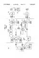
- the customer premises equipmentconsists of a set top terminal type Digital Entertainment Terminal (DET) 700 and a telephone (POTS or ISDN).
- the connections to the networkutilize Asymmetrical Digital Subscriber Line (ADSL) frequency division multiplexing technology, typically over twisted wire pair.
- ADSLAsymmetrical Digital Subscriber Line
- the ADSL connectionprovides a 1.5 Mb/s downstream video information channel, a two-way telephone connection and a two-way 16 kbit/s control channel.
- the ADSL technologyis described in more detail in the Litteral et al. Patent.
- the illustrated Video Dial Tone network architecturemay use some form of fiber extension in the actual subscriber loops, to provide services to subscribers located more than 1.5 kilo-feet from a central office (see e.g.
- the DET 700connects to an ADSL multiplexer/demultiplexer 701 similar to the in-home ADSL unit in the above discussed Litteral et al. Patent.
- Each ADSL subscriber line 703will connect to an ADSL bay 705 located in or associated with the subscriber's local telephone company central office.
- the ADSL bay 705includes an ADSL multiplexer/demultiplexer similar to the central office ADSL unit in the above discussed Litteral et al. Patent.
- the ADSL bay 705provides transport for voice signals on the subscriber loop to and from the associated voice switch 707.
- the ADSL bay 705also connects to an access concentrator 709 for providing two-way signaling connections through an X.25 type packet switched data network 711.
- the ADSL bay 705also receives broadband digital signals for downstream transport over the ADSL line 703 to each subscriber's premises from a digital cross connect switch 713, labelled "Access DCS" in the drawing.
- One ADSL line to the homecarries one channel of video programming and provides a single output channel. The output channel can provide a video signal to a VCR or to the TV set 700'.
- the various Access DCS switches throughout the networkare controlled by switch controller 712.
- the ADSL bay 705connects to the Access DCS 713 via an appropriate number of local DS1 connections 715.
- the ADSL baywill be located in a remote central office facility.
- Such a remote ADSL bayconnects to the Access DCS 713 via a SONET type optical fiber link 717 providing an appropriate number of multiplexed channels to service the number of subscribers connected to the particular ADSL bay.
- the Access DCS 713provides both point-to-point connections and point-to-multipoint connections.
- Individualized interactive servicessuch as Video On Demand, home shopping/purchasing and banking, use point-to-point connections wherein the Access DCS connects one broadband input port from a VIP's server to one output port going to the subscriber's ADSL line.
- Narrowcast and broadcast servicesutilize point-to-multi-point connections of one input port to a plurality of output ports.
- the illustrated architecture of the Video Dial Tone networkutilizes two levels of gateways, both of which will communicate with subscribers' DET's via the X.25 data network 711 and the signaling channel on the ADSL subscriber loops 703.
- the level 1 gateway 721performs a variety of network connectivity related functions, including communications port management of transmissions of information between subscribers and servers, processing of billing information and session management.
- a level 2 gatewayprovides a number of services for the Information Providers. These services include transmission of menus of available information to subscribers, searches of available information, targeted advertisement insertion, previews, trailers, control of an associated file server, etc.
- the Video Dial Tone network of FIG. 6provides video on demand and closely related interactive multimedia services.
- the subscribercan send a request for a particular movie, and the VIP's server will retrieve and transmit that movie as an MPEG digital data stream on the 1.5 Mb/s downstream channel to the digital audio/video processor in the subscriber's DET 700.
- the DETconverts the digital data stream to a signal for driving a standard television set for real time viewing of the movie by the subscriber.
- the loader routine and/or operating system within the DETwill control wake up, and the DET will transmit an initial message intended for the level 1 gateway.
- the messageis carried over the 16 kbit/s signaling channel on the ADSL subscriber's line.
- the access concentrator 709uses the X.121 address of the level 1 gateway 721 and the X.121 address associated with the calling subscriber's line 703 to initiate an X.25 packet data call to the level 1 gateway 721.
- the access concentrator 709packetizes each message from the DET 700 and adds header information to facilitate transport through an assigned virtual circuit through the X.25 network 711 to the gateway 721.
- the level 1 gateway 721transmits ASCII text representing one ore more pages of a VIP selection menu back to the DET 700 through the assigned virtual circuit through the X.25 network 711 and the signaling channel on the subscriber's line 703.
- the DET 700Upon receipt of the menu data, the DET 700 would display an initial selection menu on the subscriber's television set 700'.
- the subscribermay review the menu on their television set, and then input a selection using the infrared remote control device, either by moving a cursor to an appropriate point on the screen and hitting ⁇ ENTER> or by inputting digits followed by ⁇ ENTER>.
- the DET 700will transmit an appropriate data signal upstream through the network to the level 1 gateway 721.
- the access concentrator 709identified the subscriber and included an X.121 address for the X.25 network port assigned to the subscriber in the initial signaling packet sent through the X.25 network.
- the level 1 gateway 721 receiving X.25 packets of DET signaling datatherefore knows the X.121 address of the calling subscriber.
- the level 1 gateway 721uses that information together with the VIP selection input to initiate an X.25 data call to the VIP's level 2 gateway to ask if the subscriber is a valid customer of the particular VIP.
- the level 1 gateway 721initiates a call through switch controller 712 to instruct the appropriate digital cross connect switch DCS 713 to set up a downstream broadband link from the VIP's file server to the subscriber's DET 700 and drops the X.25 communication link to the DET.
- the VIP's level 2 gatewayinitiates an X.25 packet data call to the subscriber's DET 700. Completion of set-up of both the broadband link and the X.25 signalling link to the DET establishes an interactive video session between the VIP's gateway and server system 752 and the subscriber's DET 700.
- the level 2 gatewayexecutes a two-way communication with the DET 700 through the X.25 network 711 and the signaling channel to obtain a selection or other relevant input from the subscriber.
- the level 2 gatewayprovides a signal to the associated file server instructing the server to initiate transmission of selected audio/video program materials from memory through the output port which the DCS 713 has currently connected to the subscriber's line 703.
- the connection through the DCSroutes the downstream broadband transmission to the ADSL bay 705, and within that bay, to the ADSL multiplexer/demultiplexer serving the subscriber's line for transmission over the line 703.
- the ADSL multiplexer/demultiplexer 701demultiplexes the broadband signal carrying MPEG encoded audio/video material and applies that signal to the subscriber's DET 700 for decoding and display on the television set 700'.
- the prior art video dial tone networkmakes no use whatsoever of routing control functionality of the existing telephone network.
- the gateways and serversare all separate components newly developed and added over and above the telephone network. Development and deployment of such new equipment adversely impacts the cost of implementing the video dial tone network.
- gatewaysin the manner discussed above results in multiple call switching to set up each individual interactive broadband session between a service provider (VIP) and the subscriber's DET.
- VIPservice provider
- the X.25 communication between the DET and the level 1 gatewayis a first call.
- the X.25 communication between the level 1 and level 2 gateways to determine the validity of the calling subscriberis a second call.
- the switch controller 712typically comprises another data communication system to permit the level 1 gateway to control a plurality of DCS switches.
- the instruction to set up a broadband link through a selected DCStherefore may also be viewed as another data call, i.e. between the level 1 gateway and the particular DCS 713 which will provide the switched broadband connection.
- the two-way X.25 signaling connection between the level 2 gateway and the subscriber's DETwould be a fourth call, and the fifth and final call through the network would be the actual broadband link downstream from the server to the DET.
- Such multiple switchingis an inefficient use of resources and consumes excessive time during initial set-up of sessions between the DET and the service provider's equipment.
- AINAdvanced Intelligent Network
- AINAdvanced Intelligent Network
- local and/or toll offices of the public telephone networkdetect one of a number of call processing events identified as AIN "triggers". For ordinary telephone service calls, there would be no event to trigger AIN processing; and the local and toll office switches would function normally and process such calls without referring to the central database for instructions.
- An office which detects a triggerwill suspend call processing, compile a call data message and forward that message via a common channel interoffice signalling (CCIS) link to an Integrated Service Control Point (ISCP) which includes a Multi-Services Application Platform (MSAP) database. If needed, the ISCP can instruct the central office to obtain and forward additional information. Once sufficient information about the call has reached the ISCP, the ISCP accesses its stored data tables in the MSAP database to translate the received message data into a call control message and returns the call control message to the office of the network via CCIS link. The network offices then use the call control message to complete the particular call.
- CCIScommon channel interoffice signalling
- MSAPMulti-Services Application Platform
- Papanicolaou et al. U.S. Pat. No. 5,278,889discloses a two-way video telephone system using a combination of a two-way cable television distribution system and an intelligent voice telephone network.
- the video distribution networks usedapparently are existing frequency division multiplexed analog transmission systems.
- a central databaseresponds to video telephone call dialing information by providing instructions to the network to route the video portion of the call through a digital inter-exchange carrier network between points of presence of two of the cable television distribution networks.
- the present inventionaddresses the above needs by controlling various nodes or switching points in the network, which perform routing functions for each of the different types of services, from a central controller.
- the various nodesall are capable of recognizing certain call processing events as triggers. In response to a trigger, such a switching point will suspend processing of the particular call and obtain routing instructions from the central controller as to how to complete call processing.
- the inventionrelates to methods, networks and network components for providing centralized control of an integrated network offering at least voice grade telephone services and broadband communication services and preferably switched packet data services as well.
- a first aspect of the inventionrelates to an integrated communication system of the advanced intelligent network (AIN) type.
- the systemincludes a telephone central office switching system and at least one local router.
- the telephone central office switching systemdetects triggering events during processing of certain telephone calls.
- the local routeris often referred to as a host digital terminal or "HDT".
- the local routerselectively provides switched telephone call communications services to a plurality of telephone stations coupled thereto.
- the local routeralso selectively provides broadband digital services to a plurality of digital terminals coupled thereto.
- the local routeris capable of detecting triggering events. Broadly, the router detects such events during set up of at least some of the selective broadband digital services. In the preferred embodiment described in detail below, the local router detects trigger events during processing of voice telephone calls and packet data calls, as well.
- the inventive communication systemalso includes a central data base, separate from the telephone central office switching system and the local router.
- This data basestores data for generating control signals for controlling at least some of the telephone call communications services provided by the telephone central office switching system and at least some of the selective broadband digital services provided by the local router.
- a signaling communication systemseparate from the trunk circuits, carries two-way signaling data between the central data base and the telephone central office switching system and the local router. The telephone central office switching system and the local router each obtain control signals from the central data base via the signaling communication system in response to detection of triggering events.
- the signaling communication systemis the common channel interoffice signaling system (CCIS) used by the existing public switched telephone network.
- CCIScommon channel interoffice signaling system
- the control of the broadband service routing in essentially the same manner as AIN type telephone call routingeliminates the multiple calls needed to set up a broadband session in the prior art network of FIG. 6.
- these inventive procedureseliminate the need for an interactive provider to confirm to the network that a caller is a subscriber and then initiate both a signaling call and a broadband call back through the network as new calls to the identified subscriber's terminal in order to set up the various links necessary for an interactive session.
- the inventioncomprises a broadband call processing method in an integrated communication system.
- the systemincludes a broadband communication network, information servers connected to the broadband communication network to transmit broadband digital information via a link through that network, subscriber terminals, telephone switching offices, and a central control.
- the central controlis separate from the telephone switching offices, but it controls at least some operations of each telephone switching office.
- the inventive methodbegins with reception of a selection signal from one of the terminals at a node of the broadband communication network.
- data stored in the central controlis accessed to generate broadband control instructions.
- the accessed control datais used to control an operation of the broadband communication network to enable the one terminal to receive broadband digital information from a predetermined one of the information servers which provides the selected service.
- This AIN type call processing methodologycan be applied to control routing for a variety of broadband services available through the network.
- the selected serviceis a broadcast service
- the control datamight indicate whether or not the subscriber is in fact entitled to receive the selected program.
- This methodologywould also control routing to the level 2 gateway and broadband server operated by a selected interactive service provider. The subscriber enters a single provider selection and the control data provides the information necessary to set up both the two-way signaling link and the broadband link.
- the inventionrelates to specific broadband processing elements of the network adapted to recognize triggers and communicate with the central controller.
- one inventive elementis a local router.
- the routercomprises at least one trunk interface and at least one line interface.
- a switching system in the routerprovides telephone and broadband switching of signals between the trunk interface and the line interface.
- the routeralso includes a processor which controls the switching system.
- the processorrecognizes an event relating to selection of a broadband service as a trigger.
- a signaling communication deviceis responsive to the processor for obtaining instructions from the central controller instructing the processor how to control at least one broadband switching operation in response to the trigger.
- a broadband switching systemAs another example, another element of the inventive network is a broadband switching system.
- This inventive systemincludes a trunk interface, a line interface and a broadband switch fabric.
- the broadband switch fabricsuch as an Asynchronous Transfer Mode (ATM) routing system, selectively routes broadband signals between the trunk interface and the line interface.
- ATMAsynchronous Transfer Mode
- the inventive systemalso includes a processor which controls the broadband switch fabric and recognizes an event relating to selection of service through the broadband switch system as a trigger event.
- An associated signaling communication deviceis responsive to the processor for obtaining instructions from the central controller instructing the processor how to control the switch fabric in response to the trigger event.
- a video programcan have an associated telephone number.
- a shopping programmight advertise an existing 800 number that viewers use to call in and order advertised products.
- a vieweroperates his terminal to indicate a desire to call in.
- the terminaltransmits a message to a node of the broadband network, for example upstream to the local router or HDT.
- a queryis transmitted from the node to the central controller.
- the queryidentifies the subscriber and the transmitted video signals (i.e. the program being viewed).
- the central controlleridentifies a destination telephone number assigned to a provider of the service and a telephone number assigned to the subscriber.
- the central controllerthen provides instructions to appropriate switching points of the integrated network to ring a telephone station corresponding the destination telephone number assigned to the provider of the service and a telephone station corresponding to the telephone number assigned to the subscriber.
- components of the networkprovide a voice grade telephone communication between both telephone stations.
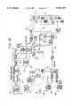
- FIG. 1Ais a schematic block diagram of an integrated Advanced Intelligent Network (AIN), in accord with the present invention, for providing voice, packet switched data and broadband (video) services.
- AINAdvanced Intelligent Network
- This drawingillustrates the telephone communication portion of the network in detail and provides a simplified functional illustration of some of the broadband network components.
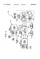
- FIG. 1Bis an alternate block diagram illustration of the exemplary integrated AIN type network, including several components of the system of FIG. 1A, with additional details regarding the broadband components.
- FIG. 2is a more detailed diagram of an SSP type central office (CO) used in the preferred intelligent network implementation of the present invention to provide switched or selective communications links for voice and/or packet data services and associated signaling.
- COcentral office
- FIG. 3is a more detailed diagram of an SSP type Asynchronous Transfer Mode (ATM) switching system used in the preferred intelligent network implementation of the present invention to provide switched or selective communications links for broadband (video) and/or packet data services.
- ATMAsynchronous Transfer Mode
- FIG. 4is a more detailed diagram of an SSP type local router, in this case a Host Digital Terminal (HDT), used in the preferred intelligent network implementation of the present invention.
- HDTHost Digital Terminal
- FIG. 5is a more detailed diagram of an Integrated Service Control Point (ISCP) used as the central controller in the preferred intelligent network implementation of the present invention.
- ISCPIntegrated Service Control Point
- FIG. 6illustrates an exemplary prior art configuration of a video dial tone network.
- AINAdvanced Intelligent Network
- ATMAsynchronous Transfer Mode
- CCISCommon Channel Inter-office Signaling
- DRSData and Reporting System
- HDTHost Digital Terminal
- ISCPIntegrated Service Control Point
- ISDNIntegrated Service Digital Network
- Interworking UnitIWU
- MPEGMoving Picture Experts Group
- MSAPMulti-Services Application Platform
- ONUOptical Network Unit
- PVCPermanent Virtual Circuit
- POTSPlain Old Telephone Service
- SCPService Control Point
- SMSService Management System
- SSPService Switching Point
- STPSignaling Transfer Point
- TCAPTransaction Capabilities Applications Protocol
- VCI/VPIVirtual Circuit Identifier/Virtual Path Identifier
- VCPVideo Information Provider
- VUVideo Information User
- FIG. 1Aillustrates an integrated advanced intelligent dial tone network providing voice, data and broadband (e.g., video) communications connectivity.
- FIG. 1Bis an alternate view of that network showing the data and broadband communications elements in more detail.
- a local telephone operating companyTELCO
- TELCOlocal telephone operating company
- a number of independent information providersoffer CATV type broadcasts of broadband information services through the network.
- Other information providersoffer interactive broadband services, such as video on demand.
- a single centralized controllermaintains a control data base and uses data from that data base to provide unified high level control over communications connectivity for the various types of communications services provided through the integrated network.
- Various switching points distributed throughout the networkrecognize triggering events and communicate with the central controller to determine how to process broadband, packet data and voice grade telephone calls.
- the inventionextends the AIN architecture and call processing techniques, developed for voice telephone service, to control packet data and broadband services.
- the control functions performed by the SSP and ISCP on broadband callsessentially eliminates or replaces the functionality of the level 1 gateway in the prior art network.
- the presently preferred embodimentutilizes the Integrated Services Control Point (ISCP) of the AIN telephone network as the centralized controller, although other controllers or network nodes could perform this function.
- ISCPIntegrated Services Control Point
- the switch points communicating with and controlled by the ISCPare referred to herein as Service Switching Points.
- Service Switching Points, or ⁇ SSP's ⁇are appropriately equipped programmable switches present throughout the network, which recognize AIN type calls, launch queries to the ISCP and receive commands and data from the ISCP to further process the AIN calls.
- each central office (CO) telephone switching system 11, 17is labeled as an "SSP.”
- SSP-CO'sare end offices. All of the end office telephone switches 11, 17 are equipped and programmed to serve as SSP's.
- the illustrated embodimentis perhaps an ideal implementation which would make a variety of Advanced Intelligent Network (AIN) type telephone services widely available at the local office level throughout the network.
- AINAdvanced Intelligent Network
- Other AIN implementations for telephone servicesprovide the SSP functionality only at selected points in the telephone portion of the network, and end offices without such functionality forward calls to an SSP switching office having tandem switching capabilities.
- SSP capable telephone central office switching systemstypically consist of a programmable digital switch with CCIS communications capabilities.
- SSP capable telephone CO switchis a 5ESS type switch manufactured by AT&T; but other vendors, such as Northern Telecom and Seimens, manufacture comparable digital switches which could serve as the SSP-CO's.
- these CO switcheswill also include packet data switch capabilities, so that one switching system can offer both voice and packet data communication services.
- the structure of an exemplary COwhich may serve as the SSP type CO's in the system of FIG. 1A will be discussed in more detail below, with regard to FIG. 2.
- the SSP-CO'sconnect to and provide telephone services to voice grade type telephone stations 219.
- the voice grade type terminals 219, 219'can comprise any communication device compatible with a voice grade type telephone line.
- the term "telephone station”broadly encompasses telephones and any other device compatible with a voice grade telephone circuit, for example, station devices such as facsimile machines, modems, etc.
- the SSP-CO'salso provide packet switched data services to end user data equipment, represented by exemplary terminal 218.
- the SSP type CO's 11 and 17connect to a first local area STP 23.
- Other telephone SSP-CO'smay connect to additional local area STP's, such as the STP 25, as needed to meet projected telephone traffic demands.
- the STP's 23 and 25also provide access to the signaling system 7 (SS#7) network for other SSP capable components of the integrated voice, data and broadband network.
- the connections to the STP'sare for signalling purposes.
- each local area STPcan connect to a large number of the SSP-CO's.
- the telephone central office SSP'sare interconnected to each other by voice and/or packet data trunk circuits (illustrated in FIG. 1A as bold lines) for carrying voice grade telephone services and packet data services.
- the local area STP's 23 and 25, and any number of other such local area STP'scommunicate with a state or regional STP 31 which in turn provides communications with the ISCP 40.
- the STP hierarchycan be expanded or contracted to as many levels as needed to serve any size area covered by the Advanced Intelligent Network (AIN) and to service any number of stations and central office switches.
- AINAdvanced Intelligent Network
- certain voice/data switching offices within the networkmay function primarily as tandem type offices providing connections between trunk circuits only.
- the links between the telephone type central office switching systems (CO's) and the local area STP's 23 and 25are typically SS#7 type CCIS interoffice packet switched data communication channels.
- the local area STP'sare in turn connected to each other and to the regional STP 31 and the regional STP 31 also communicates with the ISCP 40, all via a packet switched network which preferably also is SS#7.
- the above described data signalling network between the SSP type central offices and the ISCPis preferred, but other signalling networks could be used.
- STP's and packet networksinstead of the CCIS links, STP's and packet networks, a number of central office switches and an ISCP could be linked for data communication by a token ring network. Combinations of SS#7 and other data networks may be used.
- the exemplary ISCP 40 shown in FIG. 5communicates via the STP(s) but also may connect to a parallel signaling data network for communication with certain network nodes.
- the SSP capabilitymay not always be available at the local telephone office level, and several other implementations might be used to provide the requisite SSP capability for telephone and packet data services, as will be discussed in more detail later.
- ISCPThere could be one or more ISCP's per state, to avoid overloading existing CCIS data links.
- the ISCPcould be implemented on a LATA by LATA basis or on a regional operating company basis, i.e. one database for the entire geographic area serviced by one of the Regional Bell Operating Companies. In fact, if federal regulations permitted, the database service could become nationwide.
- the ISCP 40includes a Service Management System (SMS) 41, a Data and Reporting System (DRS) 45 and the actual database referred to as the Service Control Point (SCP) 43.
- the ISCPalso typically includes a terminal subsystem referred to as a Service Creation Environment or SCE 42 for programming the database in the SCP 43 for the services subscribed to by each individual customer.
- STP 31communicates directly with the SCP database 43.
- the token ring networkmay provide an alternate access to network nodes through a second signaling network operating in parallel to the SS#7 network.
- the SCP database 43stores data tables used to control telephone services provided through the network to callers using telephone stations.
- the SCP 43also stores at least some data for controlling broadband services through the integrated network. These various data tables take reside in a Multi-Services Application Platform (MSAP) database maintained within SCP 43.
- MSAPMulti-Services Application Platform
- the network of FIG. 1Aalso provides integrated voice telephone service and broadband services to certain customers.
- at least one SSP-CO 17connects to a local router, which in the illustrated embodiment is a host digital terminal (HDT) 180.
- the local router HDTprovides two-way voice and packet data communications, with higher level switching for such communications being provided through one or more of the SSP-CO's.
- the local router HDTalso receives broadband inputs from an ATM (asynchronous transfer mode) switch and from other sources (shown in FIG. 1B) as discussed later.
- the HDT 180provides broadband, voice and data services through optical fibers and optical network units (ONU's) 210 to subscribers telephones and digital entertainment terminals (DET's) 217.
- ONU'soptical fibers and optical network units
- DET'sdigital entertainment terminals
- all of the local routers (HDT's) 180 in the networkare themselves equipped to function as SSP's, at least for broadband services, and preferably for voice and packet data services as well.
- the ATM switch 410also is an SSP.
- the SSP-HDT's 180 and the SSP type ATM switch 410connect to the local area STP 25 for signaling communications with each other, with the SSP-CO's and with the ISCP 40.
- some of the broadband or video information providers (VIP's) equipmentalso may connect with the SS#7 network to communicate with the ISCP type central controller. In some cases, the VIP's equipment may itself have full SSP functionality.
- many telephones 219'such as stations A, B and C, connect to end office SSP's 11 and 17, via standard existing telephone lines (or equivalents thereof). Subscribers to integrated communications services, however, communicate to an end office, such as SSP-CO 17, via transport media and routing components capable of transporting voice telephone signals as well as data and broadband information.
- SSP-CO 17transport media and routing components capable of transporting voice telephone signals as well as data and broadband information.
- the telephone functionalityappears to be the same as plain old telephone service, i.e. to the user of telephone station D, the calling operations and quality of services appear identical to those available to a person using telephone station A. Exemplary techniques for providing telephone service to a station such as telephone station D are discussed in more detail below with regard to FIG. 1B.
- the AIN topology illustrated in FIG. 1Ais exemplary in nature, and other network topologies can be used.
- the illustrated networksinclude SSP functionality in each of the end office telephone switching systems.
- at least some of the end officesmay not have SSP capabilities.
- Each such end officewould connect to a trunk which in turn feeds calls to a tandem switching system with SSP capabilities.
- the SSP tandemcommunicates with the ISCP, as in the implementation described above.
- the SSP capable end office switchesthat may be present in the network, they communicate directly with the ISCP, in the same manner as in the embodiment of FIG. 1A.
- the SSP capable tandem office switchis a digital switch, such as the 5ESS switch from AT&T; and the non-SSP type end offices might be 1A analog type switches.
- a switch point which is an SSP for one type of servicemay not serve as an SSP for another type of service.
- the HDT's 180may be SSP's for data and broadband services, but not for telephone services. In such a case, the HDT's would route telephone calls through to one of the SSP telephone switches, either an end office or a tandem office.
- TCAPTransaction Capabilities Applications Protocol
- the TCAP protocolprovides standardized formats for various query and response messages. Each query and response includes data fields for a variety of different pieces of information relating to the current call. For example, an initial TCAP query from the SSP includes, among other data, a "Service Key" which is the calling party's address. TCAP also specifies a standard message response format including routing information, such as primary carrier ID, alternate carrier ID and second alternate carrier ID and a routing number and a destination number.
- the TCAPspecifies a number of additional message formats, for example a format for a subsequent query from the SSP, and formats for "INVOKE” messages for instructing the SSP to play an announcement or to play an announcement and collect digits and a "SEND TO RESOURCES" message to instruct the SSP to route to another network node.
- FIG. 1Bshows the telephone portions of the network is less detail than FIG. 1A, but FIG. 1B illustrates the broadband distribution systems and associated control signaling network in greater detail.
- the integrated broadband network of the present inventionwill provide broadcast video distribution, archival video services and interactive multi-media services as well as a suite of narrowband services including plain old telephone service.
- FIG. 1Aincludes a simplified illustration of a portion of the broadband distribution elements of the integrated network. Subscribers having broadband service would obtain all services through optical fiber connections to an HDT 180 and an ONU 210. A single drop may be used between the ONU 210 and the subscriber premises to carry voice, signaling and broadband information, and only a single connection is illustrated for simplicity.
- a coaxial cablecarries the downstream broadband information and the two-way signaling information between the ONU 210 and the DET's 217 (only one shown) on the subscriber premises.
- a separate twisted wire paircarries telephone service signals (POTS or ISDN) between the ONU and the telephone station(s) D at the subscriber premises.
- POTStelephone service signals
- the HDTcommunicates with the SSP type CO 17 for providing connected subscribers with telephone services.
- the HDT, the ONU and the optical fiberseffectively function as an optical type subscriber loop carrier system.
- the SSP-HDTmay itself act as an end office or PBX type switch.
- the SSP-COmay route all telephone calls to the associated CO for further processing.
- the SSPprocesses outgoing telephone calls from telephone type equipment, such as station D, as well as incoming calls directed to that equipment in essentially the same manner as for calls to and from lines having only POTS type service, e.g. to standard telephone stations A and B.
- the HDT 180receives ATM broadband signals from servers operated by interactive services providers through an ATM switch 410 and from other sources such as broadcast ATM sources or servers shown in more detail in FIG. 1B.
- the HDThas full SSP capabilities, essentially in the same manner as the SSP type CO's 11 and 17, discussed above.
- the HDTtherefore also conducts signaling communications with the ISCP 40 and with other components discussed in more detail below, to provide subscriber requested broadband services through the DET 217 and the associated television set 217'.
- the inventioncould be practiced in a network using ADSL technology and/or digital cross connect switching similar to those features in the prior art network of FIG. 6 or in a hybrid fiber coax network using radio frequency transport of digitized, compressed video signals as in the Ser. No. 08/304,174 case noted earlier.
- the illustrated embodimentutilizes an advanced fiber to the curb system with ATM (Asynchronous Transport Mode) transport, similar to one of networks disclosed in commonly assigned application Ser. No. 08/250,792, filed May 27, 1994, entitled “Full Service Network", the disclosure of which is incorporated herein entirely by reference.
- the inventioncould easily be adapted to control a variety of other types of video dial tone networks.
- the broadcast video serviceswill initiate from a broadcast video source or server 101.
- the broadcast server 101includes an actual analog video source 110. Although only one is shown, a typical broadcast service provider will have a plurality of such sources.
- the analog signal from the sourceis carried by any convenient means, such as an optical fiber, etc.
- Means(not shown) are provided as necessary to convert analog video transmission signals, e.g. NTSC broadcast signals, to baseband video and audio signals.
- the baseband signalsare applied to a real time encoder 110.
- the real time encoder 110digitizes the audio and video signals and performs data compression.
- the encoderwill encode the program signal into an MPEG 2 format although other digital compression encoding schemes may be used, such as DIGICIPHERTM.
- MPEGmoving picture experts group
- MPEG 2is a second generation compression standard for packetized transport of one or more compressed video program signals in a single stream.
- a number of specific compression algorithmswill satisfy MPEG requirements.
- MPEGpermits encoding of audio/video program materials into digitized, compressed format at rates in the range of 1.5 to 6 Mbits/sec.
- the illustrated real time encoder 120preferably is set up as a bank of encoders to process six sets of analog audio/video program signals in parallel.
- the bank of encoders 110produces six 6 Mbits/sec MPEG 2 bit streams, which are combined together with appropriate overhead informnation into a single 45 Mbits/sec DS-3 type signal.
- the DS-3 signal from the encoder 110is input to an interworking unit (IWU) 130.
- the interworking unit 130is the actual input point for the encoded broadcast video information into the network.
- the exemplary network illustrated in FIG. 1Butilizes asynchronous transfer mode (ATM) switching to transport all video information, including the broadcast video information.
- ATMis a packet oriented time division multiplexing technique.
- informationis organized into cells having a fixed length and format. Each cell includes a header, primarily for identifying cells relating to the same virtual connection, and an information field or "payload".
- a 53 octet ATM cellwould include a cell header consisting of 5 octets and a payload consisting of 48 octets of data.
- the ATM cell header informationincludes a virtual circuit identifier/virtual path identifier (VCI/VPI) to identify the particular communication each cell relates to.
- VCI/VPIvirtual circuit identifier/virtual path identifier
- the VCI/VPIwill identify a particular program channel.
- the VCI/VPI in each header of the ATM cellswould effectively identify a specific end point of the virtual communication link.
- ATM transferis asynchronous in the sense that the recurrence of cells that contain information from any particular sender is not necessarily periodic.
- Each device using the ATM networksubmits a cell for transfer when they have a cell to send, not when they have an assigned or available transmission time slot.
- ATMallows any arbitrary information transfer rate up to the maximum supported by the ATM network, simply by transmitting cells more often as more bandwidth is needed.
- all video materialswill be transferred at a constant, standardized bit rate, however, preferred later generations of the network will utilize the ATM capabilities of the network to permit transmission of video information over channels of different bit rates, e.g. 1.5 Mbits/sec, 3 Mbits/sec, 6 Mbits/sec, etc. It will also be possible to vary the bit rate during communication on an as needed basis.
- the interworking unit (IWU) 130grooms the continuous MPEG 2 bit streams of the broadcast services for ATM cell stream transmission over optical fiber transport links. For example, the interworking unit maps MPEG transport stream packets into ATM cells. Specifically, the interworking unit will divide the MPEG packets into appropriate length payloads and combine the payload data with appropriate cell headers, necessary for ATM transport. In an initial implementation, downstream links would carry an OC-12 bit rate, but higher rate transports such as OC-48 will be used in later implementations. Assuming use of OC-12, one such transport link will normally carry the equivalent of 12 DS-3's. However, conversion into ATM cell format with associated headers imposes added overhead requirements on the data transmissions. In the presently preferred embodiment, one interworking unit 130 therefore processes up to ten DS-3 signals to produce an ATM bit stream at the OC-12 rate.
- a transport interface 140converts the electrical signal from the interworking unit 130 into an optical signal and transmits the optical signal through fiber 150 to an adaptive digital multiplexer (ADM) identified in the drawing as a video bridging and insertion device 160.
- ADMadaptive digital multiplexer
- the ADM 160performs three functions, passive bridging, active bridging and insertion of signals from other broadcast service providers (if any). The three functions may actually be separate, but in the preferred embodiment would be performed by elements collocated within the one network component ADM 160.
- the real time encoders 120each output a single DS-3 signal comprising up to 6 MPEG 2 bit streams.
- the interworking unit 130processes up to ten DS-3 signals to produce an ATM bit stream at the OC-12 rate. Consequently, one broadcast video source 101 may produce as many as 60 channels of CATV type broadcast programming for transport over one OC-12 type SONET optical fiber 150. Many providers, however, may not choose to broadcast so many channels. For example, the provider operating broadcast video source 100 may offer only 42 channels. Such an ATM channel transmission on the optical fiber 150 will not utilize the entire OC-12 channel capacity of that fiber. In the specific example, the 42 channels together require the equivalent of 7 of the available 10 DS-3's.
- the illustrated architecturepermits a second broadcast service provider to utilize the transport capacity not used by the first provider.
- the second broadcast service providerwould offer additional channels from a separate second source 101'.
- the broadcast source type server 101'is essentially identical in structure and operation to the source server 101, but the source/server 101' will offer up to the number of channels necessary to fill the OC-12 transport capacity. In the example, if the source 101 transmits 42 channels (7 DS-3's) via the fiber 150, the second source 101' could transmit up to 18 additional channels (3 DS3-'s).
- the function of the insertion device in the ADM 160is to combine the signals from the two sources into a single OC-12 rate signal (10 DS3's in ATM cell format) for further transmission through the optical network.
- the two bridging functionsfacilitate dissemination of the broadcast material throughout the entire network.
- the passive bridging elementsare optical splitters for splitting one OC-12 optical signal from the insertion device into a number of duplicates thereof, e.g. 1:2, 1:4, 1:8, etc.
- the active bridging elementsconvert an optical signal to an electrical signal, regenerate the electrical signal and convert the regenerated signal back to an optical signal for application to multiple output ports.
- the optical OC-12 output signals from the bridging componentsare transmitted over a large number of optical fibers 170 to host digital terminal type local routers throughout the network service area.
- One host data terminal (HDT) 180is shown in FIG. 1B as a representative example.
- the digital entertainment terminal (DET) in the subscriber's homeprovides a signal identifying the selected channel to the HDT 180.
- the signaling between the digital entertainment terminal (DET) and the HDT 180 and the real time control of the routing by the HDT 180will be discussed in more detail below.
- the ATM cell stream from an optical fiber 170is applied to an ATM switching system of some type.
- the control functionality of the HDT 180 and the interaction of the SSP-HDT 180 with the ISCP 40 to achieve that controlwill be discussed in detail later.
- One HDTwill communicate with a large number of optical network unit (ONU's) via pairs of optical fibers 190.
- each home or living unitwill have as many as four DET's.
- Each ONU 210 and the downstream fiber of the pair 190 to the ONU 210will provide downstream video services to a number of homes, e.g. 8 to 24.
- the transmissions on the downstream fibers between the HDT and the ONU's 210are synchronous, although the video information remains in ATM cell format.
- Each DET served by an ONU 210is assigned a specified time slot on the downstream fiber of a pair 190.
- the HDT 180includes a component which is essentially a non-blocking type ATM switch (discussed in more detail below with regard to FIG. 4).
- the HDT 180accesses the appropriate input circuit interface unit and identifies each ATM cell from that fiber interface for which the header information indicates that the cell represents information for the selected broadcast channel.
- the identified ATM cellsare bridged by the internal ATM switch to a line interface unit providing transmissions over the optical fiber 190 to the particular ONU 210 which services the requesting subscriber's premises.
- the HDTselects each ATM cell for transmission to a specific DET
- elements on the line interface card communicating with the particular ONUwill buffer the cell as necessary and place the cell in the time slot for that DET on the downstream fiber of optical fiber pair 190.
- the cells selected for a particular DET, together with cells going to other DET's served by the same ONU multiplexed into their respective time slots,are applied to an electrical to optical converter and transmitted over the downstream fiber to the ONU 210 serving the particular subscriber's premises.
- the basic purpose of the ONU 210is to desegregate the HDT side links into individual customer links and provide optical to electrical conversion for electrical delivery to the individual subscribers' premises.
- the drop cable to each subscriber's premisescomprises a coaxial cable for carrying the video and/or digital data signals and a twisted wire pair for carrying telephone signaling.
- ADSL communications over twisted wire paircould be used between the ONU and the subscribers premises.
- the ONU 210includes means to convert optical signals received over the downstream fiber of the pair 190 to electrical signals and transmit signals from each DET's assigned time slot down over the coaxial cable to the subscriber's premises.
- the ONU 210provides two-way conversion between optical and electrical and between digital and analog signals for voice telephone service over the twisted wire pairs.
- the ONU'salso provide two-way conversion between optical and electrical and multiplexing and demultiplexing for the signaling channels to/from the DETs 217.
- the DET 217responds to user inputs on the built in keypad or the remote control by transmitting appropriate data signals over a narrowband channel on the coaxial drop cable to the ONU 210.
- Each ONU 210multiplexes the user input data signals from the DET's 217 that it services together and transmits those signals to the SSP-HDT 180 over an upstream fiber of the optical fiber pair 190.
- the SSP-HDT 180processes those signals and may interact with the ISCP 40, as discussed in more detail below, to determine how to route the broadband service call.
- the SSP-HDT 180will respond similarly to signals from a DET 217 relating to packet data calls and preferably processes voice calls in a similar manner.
- the HDT 180transmits the upstream control signals to control elements at the respective destination.
- the VIPwould operate a control element identified as a level 2 gateway, of essentially the same type os the level 2 gateway in the prior art system of FIG. 6.
- the HDT's 180communicate with the level 2 gateways through an X.25 type data call through the packet switched data communication portion of the integrated network. This packet data call operates in parallel to the broadband link between the VIP's broadband file server 403 and the DET 217.
- the HDT 180For VIP's connected to the ATM switch 410, future implementations will use ATM communications through that switch for the two-way signaling communication between the level 2 gateway and the DET 217.
- the HDT 180For an established packet data call, e.g. to the packet data device 218 (FIG. 1A) the HDT 180 simply forwards upstream data to the next higher packet data node in the network, typically the CO 17, for further transport to the other party to the call.
- the HDTwould route downstream packet data received from the higher level packet node through the signaling channel to the calling subscriber's DET.
- the network of FIG. 1Balso includes a billing system 15 operated by the TELCO.
- the billing systemcommunicates with all of the SSP's, either through the CCIS network and STP's or through a separate parallel data communication link.
- a complete communication linkis set up, between telephone stations, between a DET 217 and a packet data device 218, between an interactive broadband service VIP 400 and a DET 217 or to supply a broadcast service to a DET 217, one or more of the SSP's formulates an appropriate message for the billing system 15.
- the messageidentifies the subscriber, the type of communication (e.g. to a broadband VIP or selection of the particular channel) the other party to the communication (e.g. the called party or the broadcast VIP) and the start time.
- the same SSPformulates a similar message to the billing system 15 when the broadband transmissions end and the communication link is torn down. These messages may be transmitted to the billing system on a real-time basis, as events occur, or the SSP's may store the various billing data and periodically upload the messages to the billing system 15.
- a power source 211supplies -130 V dc and battery reserve power, for at least telephone service, to the ONU's 210.
- the power source 211may connect to the ONU's via twisted pairs, but in the preferred embodiment, the power is carried over a coax distribution cable.
- a network interface modulecouples the set-top device or digital entertainment terminal (DET) 217 to the coaxial drop cable of the distribution network.
- the NIMincludes appropriate means to select ATM cells from its assigned time slot on the coaxial cable and strip off the ATM header information and reconstitute the digital payload data, e.g. into MPEG packetized information.
- the NIMalso provides two way signaling for transmission of narrowband data through the network, typically for control signaling purposes.
- the DET 217also includes a CPU comprising a 386 or 486 microprocessor with associated memory (RAM, ROM and EPROM), as well as an audio/video decoder controlled by the CPU.
- the audio/video decoderdecompresses the digitized broadband information.
- the preferred embodiment of the audio/video decodercomprises an MPEG video decoder, an MPEG audio decoder, and an MPEG demultiplexer for selectively routing MPEG encoded video and audio packets carried on the digital broadband channel to the MPEG video decoder and the MPEG audio decoder, respectively.
- the MPEG demultiplexerroutes data packets from the MPEG stream to the CPU for further processing, e.g. as downloaded data and/or control programming or as graphic/text information.
- the DET 217also includes a graphics display generator for generating displays of received graphics and text data output by the CPU, such as the initial turn-on selection menu, discussed in more detail below.
- the DET 217also includes digital to analog converters and appropriate drivers to produce output signals compatible with a conventional television set 217' from the decoded audio/video information and the graphics display.
- Each DETalso includes means to receive selection signals from a user and transmit appropriate data signals over a narrowband signaling channel through the network.
- the presently preferred digital entertainment terminal (DET) 217is a programmable device to which different applications programs will be downloaded from an information provider's level 2 gateway device, in order to permit the DET to interact with different information service providers and thereby offer the user totally different types of services.
- At least one VIPtypically a vendor of the DET 217, also can download portions of the operating system.
- the DET 217will permanently store only an operating system and a loader program, to control initial communications with the SSP-HDT 180. Based on this loader routine, the DET 217 will normally wake up in a CATV-like mode of operation for selecting and receiving broadcast programs.
- the DET 217will normally store an identification of the last broadcast channel viewed, in non-volatile memory, and will retain that identification in memory while the DET is off.
- the DETwill transmit a request for the last viewed channel to the SSP-HDT 180, to obtain that channel for display in the usual manner.
- the DET 217will also offer the video information user (VIU) the option to select initiation of a call to an interactive service provider through the ATM switch and or through the packet data switching function of the CO's.
- VIPvideo information user
- FIG. 2is a simplified block diagram of an electronic program controlled switch which may be used as any one of the SSP type CO's in the system of FIG. 1A and 1B.
- the CO switch 11 or 17includes a number of different types of modules.
- the illustrated switchincludes interface modules 51 (only two of which are shown), a communications module 53 and an administrative module 55.
- the SSP-COprovides switched voice grade telephone services and packet switched data services (X.25 and/or ISDN).
- the interface modules 51each include a number of interface units 0 to n.
- the interface unitsterminate lines from subscribers' stations, trunks, T1 carrier facilities, etc. Where the interfaced circuit is analog, for example a standard subscriber telephone loop to station 219' (FIG. 1A), the interface unit will provide analog to digital conversion and digital to analog conversion. Alternatively, the lines or trunks may use digital protocols such as T1 or ISDN, e.g. to provide transport to various combinations of voice and packet data equipment.
- the trunk circuit to one of the HDT's 180will take the form of a pair of optical fibers providing two-way transport for a number of multiplexed DS-1 type signals. Each DS-1 comprises 24 slots, each slot providing transport for a 64 kbits/s DS-0 slot.
- Each DS-0 slot(equivalent to an ISDN B-channel) can transport digitized voice or packets of data, e.g. in X.25 format.
- Each interface module 51also includes a digital service unit (not shown) which is used to generate call progress tones.
- Each interface module 51includes, in addition to the noted interface units, a duplex microprocessor based module controller and a duplex time slot interchange, referred to as a TSI in the drawing.
- Digital words representative of voice information or packet data informationare transferred in two directions between interface units via the time slot interchange (intramodule call connections) or transmitted in two directions through the network control and timing links to the time multiplexed switch 57 and thence to another interface module (intermodule call connection).
- the time multiplexed switch 57may consist of a single switch fabric capable of time division multiplexed routing of packets representing both voice and data.
- the switch 57may comprise separate switch modules for time division multiplexed routing of the voice words and the data packets.
- the communication module 53includes the time multiplexed switch 57 and a message switch 59.
- the time multiplexed switch 57provides time division transfer of digital voice data packets between voice channels of the interface modules 51 and transfers data messages between the interface modules.
- the message switch 59interfaces the administrative module 55 to the time multiplexed switch 57, so as to provide a route through the time multiplexed switch permitting two-way transfer of control related messages between the interface modules 51 and the administrative module 55.
- the message switch 59terminates special data links, for example a link for receiving a synchronization carrier used to maintain digital synchronism.
- the administrative module 55includes an administrative module processor 61, which is a computer equipped with disc storage 63, for overall control of CO operations.
- the administrative module processor 61communicates with the interface modules 51 through the communication module 53.
- the administrative module 55also includes one or more input/output (I/O) processors 65 providing interfaces to terminal devices for technicians such as shown at 66 in the drawing and data links to operations systems for traffic, billing, maintenance data, etc.
- I/Oinput/output
- a CCIS terminal 73 and an associated data unit 71provide a signalling link between the administrative module processor 61 and an SS#7 network connection to an STP or the like (see e.g. FIG. 1A), for facilitating call processing signal communications with other CO's, with HDT's 180 and with the ISCP 40.
- the CCIS terminal 73 and data unit or an additional terminal and data unitprovide communications between the administrative module of the CO and an appropriate billing system 15 (see FIG. 1B).
- the administrative module 55also includes a call store 67 and a program store 69. Although shown as separate elements for convenience, these are typically implemented as memory elements within the computer serving as the administrative module processor 61.
- the call store 67stores translation information retrieved from disc storage 63 together with routing information and any temporary information needed for processing the call. For example, for a switch based Centrex type service, the call store 67 would receive and store extension number translation information for the business customer corresponding to an off-hook line initiating a call.
- the call store 69would receive and store information defining various trigger events to look for during processing of the call.
- the program store 69stores program instructions which direct operations of the computer serving as the administrative module processor.
- FIG. 3is a simplified block diagram of an ATM type electronic program controlled switch which may be used as the switch 410 in the system of FIGS. 1A and 1B.
- the organization of the SSP type ATM switch of FIG. 3is substantially similar to that of the SSP-CO shown in FIG. 2, although a variety of other switch architectures may be used.
- the ATM switchincludes interface modules 451, 452 (only two of which are shown), a communications module 453 and an administrative module 455.
- the interface module 451terminates lines from VIP's equipment.
- the interface module 451includes a number of interface units 0 to n. As discussed in more detail below, these line interface units receive ATM cell streams representing broadband information from the VIP's equipment and may provide a two-way connection to the VIP's equipment for signaling information and/or data communications in ATM cell format.
- the interface module 452terminates optical fiber trunks going to the SSP-HDT's 180.
- the interface module 452includes a number of trunk interface units 0 to n. These trunk interface units transmit ATM cell streams representing broadband information to the SSP-HDT's 180 and may provide a two-way connection to the to SSP-HDT's for signaling information and/or data communications in ATM cell format.
- ATM cellsare transferred in two directions through the network control and timing links to the ATM multiplexed switch 457 and thence to another interface module in a manner similar to an intermodule call connection in the CO-SSP of FIG. 2. More specifically, in the ATM switch of FIG. 3, ATM cells from a VIP (broadband, data and signaling) are transferred from the appropriate line interface unit in module 451 through the ATM multiplexed switch 457 to a trunk interface unit in module 452 servicing the appropriate SSP-HDT. Similarly, ATM cells from an SSP-HDT (data and signaling) are transferred from the appropriate trunk interface unit in module 452 through the ATM multiplexed switch 457 to a line interface unit in module 451 servicing the particular VIP. Although labeled and described as a "switch," the module 457 may in fact utilize a variety of fabrics to achieve the necessary routing of cells between interface modules and the attendant cell policing.
- the communication module 453includes the ATM multiplexed switch 457 and a message switch 459.
- the ATM multiplexed switch 457provides the actual ATM transfer of cells between channels of the interface modules 451, 452 and transfers control data messages between the interface modules.
- the message switch 459interfaces the administrative module 455 to the ATM multiplexed switch 457, so as to provide a route through the ATM multiplexed switch permitting two-way transfer of control related messages between the interface modules 451, 452 and the administrative module 455.
- the message switch 459terminates special data links, for example a link for receiving a synchronization carrier used to maintain digital synchronism.
- the administrative module 455includes an administrative module processor 461, which is a computer equipped with disc storage 463, for overall control of operations of the SSP type ATM switching system.
- the administrative module processor 461communicates with the interface modules 451 through the communication module 455.
- the administrative module 455also includes one or more input/output (I/O) processors 465 providing interfaces to terminal devices for technicians such as shown at 466 in the drawing and data links to operations systems for traffic, billing, maintenance data, etc.
- I/Oinput/output
- a CCIS terminal 473 and an associated data unit 471provide a signalling link between the administrative module processor 461 and an SS#7 network connection to an STP or the like (see FIG. 1A), for facilitating call processing signal communications with the CO's, the HDT's and the ISCP 40.
- the CCIS terminal 473 and data unit 471 or an additional terminal and data unitprovide communications between the administrative module 455 and the billing system 15 (FIG. 1B).
- the administrative module 455also includes a call store 467 and a program store 469. Although shown as separate elements for convenience, these are typically implemented as memory elements within the computer serving as the administrative module processor 461.
- the disc memory 463stores data tables defining all possible virtual circuits through the ATM switch and the HDT's to each terminal of a customer subscribing to a particular provider's services. These data tables define the header information (e.g. VCI/VPI) and the particular fiber output port used to route cells to the correct HDT 180. These data tables thus define "permanent virtual circuits" (PVC's) between the providers 400 and the DET's 217.
- PVC'spermanent virtual circuits
- the disc memory 463would store similar PVC data tables for the signaling links.
- the program store 469stores program instructions which direct operations of the computer serving as the administrative module processor.
- the call store 467stores translation information retrieved from disc storage 463 together with routing information and any temporary information needed for processing the call.
- the call store 467would receive and store the VCI/VPI designations necessary for routing the downstream broadband information, and the two-way signaling information, from the VIP's equipment through currently available ATM virtual circuits and the HDT and ONU to the subscriber's terminal (DET) from the PVC table in the disc storage system 463.
- FIG. 4is a simplified block diagram of an electronic program controlled switch which may be used as any one of the SSP-HDT's 180 in the system of FIG. 1A.
- the SSP-HDTincludes one or more line interface modules 1851, one or more trunk interface modules 1853, a series of actual switch modules, and an administrative module 1855.
- the line interface module 1851includes a number of interface units 0 to n. These interface units terminate optical fibers providing two-way communications through the ONU's to and from the actual subscribers' stations. Part of the function of the interface units is to provide two-way conversion between electrical signals and optical signals.
- the line interface unitsalso place the broadband ATM cells, the voice telephone information, packet data information and/or signaling data in appropriate channels going to the ONU. In the opposite communication direction, the line interface units supply upstream voice telephone information, and packet and/or signaling data from the subscriber's channels on the fibers from the ONU's to appropriate switches 1858, 1859 within the HDT.
- the trunk interface module 1853includes a number of trunk interface units 0 to n. These interface units terminate a variety of packet data, voice and ATM trunk circuits. More specifically, certain of the interface units terminate optical fiber trunks carrying broadcast video service information, in ATM cell stream form, to the HDT 180. Other interface units terminate ATM cell stream fiber trunks which carry broadband information from the ATM switch 410. In the future, these interface units will also provide a termination for two-way ATM cell streams providing signaling and data communication through the ATM switch 410.
- the voice trunk interface unitsterminate standard voice trunks coupled to one of the telephone type CO's, for example SSP-CO 17 shown in FIG. 1A.
- the packet data trunk interface unitsterminate packet data trunk circuits coupled to a packet data switch, however, in the preferred implementation, the packet data switching is performed within one of the telephone type CO's, again for example the SSP-CO 17 shown in FIG. 1A.
- the packet data and digitized voicemay actually ride in different channels multiplexed onto a common trunk medium between the HDT and the CO as discussed above relative to FIG. 1B.
- the trunk circuit between the HDT 180 and the COpreferably will take the form of a pair of optical fibers providing two-way transport for a number of multiplexed DS-1 type signals.
- Each DS-1comprises 24 slots, each slot providing transport for a 64 kbits/s DS-0 slot.
- Each DS-0 slot(equivalent to an ISDN B-channel) can transport digitized voice or packets of data, e.g. in X.25 format.
- the interface unitsprovide conversions between optical and electrical.
- the trunk interface unitsalso receive the broadband ATM cells, downstream voice telephone information, and packet data information and/or signaling data in appropriate channels from the respective trunks and supply that information going to the appropriate one of the switches 1857, 1858, 1859 within the HDT.
- the trunk interface unitssupply upstream voice telephone information, and packet data from the subscribers to the appropriate trunks going to the associated CO.
- the ATM switch 1857supplies that data in ATM cell stream format through the module control to the appropriate ATM trunk interface providing upstream transmission through an optical fiber to the ATM switch 410.
- Each interface module 1851, 1852includes, in addition to the noted interface units, a duplex microprocessor based module controller. Digital words representative of voice information, packets of data and ATM cells transmitted in two directions through network control and timing links to the time multiplexed voice switch 1859, the packet data switch 1858 and the ATM multiplexed switch 1857 and thence to the other type of interface module in a manner similar to an intermodule call connection in the telephone CO of FIG. 2.
- the ATM switch 1857may comprise any routing device capable of receiving from and supplying cells to the interface modules and policing the cells.
- module 1857may consist of a token ring carrying ATM cells, and the nodes of the ring would process and police the cells as necessary to achieve the desired routing between interface modules.
- the packet switch 1858would typically be a small capacity X.25 compatible time division switch.
- the voice switch 1859would be a small capacity digital voice switch, similar to the switch module of a digital PBX. Alternatively, a single digital switch may perform the routing functions of both the packet switch 1858 and the voice switch 1859.
- the administrative module 1855includes an administrative module processor 1861, which is a computer equipped with disc storage 1863, for overall control of the HDT operations.
- the disc storage 1863stores translation tables to permit routing of voice, data and broadband information to customer premises devices.
- the disc system 1863also stores subscriber profile information and may store channel mapping tables, as discussed in more detail below.
- the administrative module processor 1861communicates with and controls the interface modules 1851, 1852 and the switches 1857, 1858, 1859.
- a CCIS terminal 1873 and an associated data unit 1871provide a signalling link between the administrative module processor 1861 and an SS#7 network connection to an STP or the like (see FIG. 1A), for facilitating call processing signal communications with the CO's, the ATM switch and the ISCP 40.
- the CCIS terminal 1873 and the data unit 1871 or an additional terminal and data unitprovide communications between the administrative module 1855 and the billing system 15 (FIG. 1B).
- the administrative module 1855also includes a call store 1867 and a program store 1869.
- the call store and the program storeare typically implemented as a memory elements within the computer serving as the administrative module processor 1861.
- the call store 1867stores translation information retrieved from disc storage 1863 together with routing information and any temporary information needed for processing the call.
- the call store 1867would receive and store channel mapping information indicating the trunk fiber and the ATM virtual circuit on the trunk fiber for each broadcast service and information identifying the broadband channel in the fiber pair 190 assigned to the DET from which the channel request originated.
- the program store 1869stores program instructions which direct operations of the computer serving as the administrative module processor.
- a central office switching system or CO shown in FIGS. 1A and 1Bnormally responds to a telephone service request on a local communication line connected thereto, for example an off-hook followed by dialed digit information, to selectively connect the requesting line to another selected local communication line, e.g. to establish a voice call communication link from telephone station A to telephone station B (FIG. 1A).
- the connectioncan be made locally through only the connected central office switching system. For example, for a voice telephone call from station A to station B, the SSP-CO 11 provides the call connection without any connection to another central office.
- the voice connectionis made through the connected central office switching system SSP-CO 11 and at least one other central office switching system SSP-CO 17 through the telephone trunks interconnecting the two central office switches.
- the central office switching systemresponds to an off-hook at one of the telephone stations and receives dialed digits from the calling station.
- the central office switching systemanalyzes the received digits to determine if the call is local or not. If the called telephone station is local and the call can be completed through the one central office, the central office switching system connects the calling station to the called station. If, however, the called station is not local, the call must be completed through one or more distant central offices, and further processing is necessary. If at this point the call were connected serially through the trunks and appropriate central offices between the caller and the called party using in channel signalling, the trunks would be engaged before a determination is made that the called line is available or busy. Particularly if the called line is busy, this would unnecessarily tie up limited voice trunk circuit capacity.
- the CCIS system through the STP'swas developed to alleviate this problem.
- the local central officesuspends the call and sends a query message through one or more of the STP's.
- the query messagegoes to the central office to which the called station is connected, referred to as the "terminating" central office.
- the terminating central officedetermines whether or not the called station is busy. If the called station is busy, the terminating central office so informs the originating central office which in turn provides a busy signal to the calling station. If the called station is not busy, the terminating central office so informs the originating central office.
- a telephone connectionis then constructed via the trunks and central offices (and/or tandem offices) of the network between the calling and called stations.
- the receiving central officethen provides a ringing signal to the called station and sends ringback tone back through the connection to the calling station.
- call processing routines discussed aboveare similar to those used in existing networks to complete calls between telephone stations. In an integrated voice, packet data and broadband AIN type network in accord with the present invention, these normal call processing routines would still be executed for completion of POTS calls and packet data calls not requiring AIN processing.
- AINAdvanced Intelligent Network
- certain telephone and packet callsreceive specialized AIN type processing under control of data files stored in the SCP database 43 within the ISCP 40.
- the SSP type local offices of the public telephone networkinclude appropriate data in the translation tables for customers subscribing to AIN services to define certain call processing events identified as AIN "triggers".
- an SSP-COUsing the translation table data from disc memory 63, an SSP-CO will detect such triggering events during processing of calls to or from such AIN service subscribers.
- the SSP type CO switchescan recognize a variety of events as triggers for activating a query and response type AIN interaction with the ISCP.
- a number of different AIN triggersare used, such as off-hook immediate, off-hook delay, dialed number, termination attempt, private dialing plan, etc., depending on the precise type of service the AIN will provide a particular subscriber. For example, if a subscriber has a speech responsive autodialing service for telephone calls, an off-hook immediate trigger might be stored in the translation table file for that subscriber in the SSP-CO.
- the SSP-COwould detect the trigger each time the subscriber goes off-hook on that line and then attempt to obtain further instructions from the ISCP.
- the ISCPwould instruct the SSP-CO to route the out-going call to a network node having speech recognition capabilities. Similar triggers are detectable by the CO's during packet data call processing, and similar triggers are detectable by SSP type HDT's and the SSP type ATM switch during voice, packet data and/or broadband call processing.
- an SSP type officeCO or tandem
- CO or tandemwhich detects a trigger will suspend call processing, compile a TCAP formatted call data message, and forward that message via a common channel interoffice signalling (CCIS) link and STP(s) to the ISCP 40 which includes the SCP database 43.
- CCIScommon channel interoffice signalling
- the ISCPaccesses its stored MSAP data tables to translate the received message data into a call control message and returns the call control message to the office of the network via CCIS link and STP(s).
- the SSPthen uses the call control message to complete the particular call through the network.
- the SSP-HDT 180treats all broadcast channel requests as AIN triggers. Input of a broadcast channel request would appear similar to an off-hook delay type trigger, used for certain types of AIN processing for voice telephone calls.
- the administrative module processor 1861 within the HDT 180would recognize the channel selection as a trigger and suspend call processing.
- the SSP-HDT 180then compiles a TCAP formatted call data message and forwards that message via a common channel interoffice signalling (CCIS) link and STP(s) to the ISCP 40 which includes the SCP database 43.
- the TCAP call data messagewould identify the subscriber and the particular one of the subscriber's DET's 217 from which the request originated and would include at least the input digits representing the broadcast service request, typically the selected channel.
- the messagemay identify one of a plurality of broadcast service provider type VIP's accessible through the network, either based on a concurrent VIP selection or on an earlier choice of a broadcast service provider.
- the ISCP 40accesses its stored data tables to translate the received message data into a call control message. For example, the ISCP 40 may determine that the requested channel is a basic service broadcast channel offered by the particular VIP, with no access restrictions, and formulate a message identifying the respective optical fiber 170 and the particular DS-3 and ATM virtual circuit on that fiber which transports the requested program service. The ISCP 40 returns the call control message to the SSP-HDT 180 via CCIS link and STP(s). The SSP-HDT then uses the call control message to complete the particular broadband call. In the basic service example given above, the SSP-HDT 180 would respond by supplying the cell stream for the requested service to the subscriber's DET 217.
- the HDT 180would accumulate usage data for the subscribers serviced thereby.
- the HDT 180would periodically upload such usage data to an appropriate billing system 15 operated by the TELCO.
- the billing systemwould maintain data tables for broadcast service charges for services offered by the various broadcast VIP's. Any usage charges for broadcast viewing would appear on the subscriber's telephone bill.
- the TELCOcollects the broadcast viewing charges and splits the collected monies with the various broadcast VIP's, on some agreed percentage basis or the like.
- certain relevant control datacould be stored in subscriber profile tables in the disc storage 1863 in each HDT 180.
- the broadcast VIP'swould provide provisioning data for downloading and storage in the HDT 180, including broadcast channel mapping information and subscriber authorization control information.
- the channel mapping informationspecifies what programs are carried on each ATM virtual circuit, within each DS-3, on each respective optical fiber 170.
- the administrative module processor 1861 within the HDT 180accesses the channel mapping information in response to each program selection by a subscriber to route the corresponding ATM cell stream to the requesting DET 217.
- the authorization control datawould identify each VIP's pay-per-view or premium program services as AIN triggers.
- the authorization control datamay also identify certain channels that the subscriber has identified for restricted access, i.e. not for viewing by children, as AIN triggers. These broadband triggers are similar to dialed number triggers used to trigger certain types of AIN processing for voice telephone calls.
- the administrative module processor 1861 within the HDT 180would recognize whether or not the channel selection constituted a trigger based on information retrieved from disc storage 1863. If not, the administrative module processor 1861 would instruct the internal ATM switch 1857 and the line interface module servicing the subscriber to route the ATM cells for the selected channel to the subscriber's DET 217, using the channel mapping data in the manner outlined above. However, if the selected channel is some form of restricted service channel, e.g. premium service, pay-per-view, or restricted by designation by the subscriber, then the administrative module processor 1861 would recognize the channel selection as a broadband type AIN trigger.
- restricted service channele.g. premium service, pay-per-view, or restricted by designation by the subscriber
- the SSP-HDT 180Upon detecting that the channel selection is a broadband type AIN trigger, the SSP-HDT 180 suspends call processing, compiles a TCAP formatted call data message and forwards that message via a common channel interoffice signalling (CCIS) link and STP(s) to the ISCP 40.
- the ISCP 40accesses its data tables stored in SCP database 43 to translate the received message data into a call control message. For example, the ISCP 40 may determine that the requested channel is a premium channel and whether or not the requesting subscriber is currently entitled to receive that service. If so, the call control message would include appropriate instructions to route the cell stream for the requested service to the subscriber's DET 217.
- the ISCP 40returns the call control message to the SSP-HDT 180 via CCIS link and STP(s).
- the SSP-HDTthen uses the call control message to complete the particular broadband call by supplying the cell stream for the requested service to the subscriber's DET 217.
- the HDT 180would accumulate usage data for the subscribers serviced thereby.
- the HDT 180would upload such usage data to the billing system 15 operated by the TELCO for processing in the manner discussed above.
- the ISCP 40would instruct the SSP-HDT 180 to prompt the subscriber and collect digits.
- the SSP-HDT 180would transmit a page of text/graphics via the signaling channel to the subscriber's DET requesting input of a code.
- the subscriberreviews the prompting message and inputs an appropriate number of digits by operating the remote control of the DET 217.
- the DET 217transmits a corresponding message upstream through the signaling channel identifying the keys operated by the subscriber in response to the prompt.
- the SSP-HDT 180receives the message and relays the identified key digits through the CCIS network (STP's and SS#7 links) to the ISCP 40.
- the ISCP 40compares the digits to one or more valid PIN numbers associated with the requesting subscriber and/or the particular broadcast service. If the input digits correspond to a valid PIN, then the ISCP 40 returns a call control message to the SSP-HDT 180 instructing it to proceed with routing of the appropriate ATM cell stream for the requested broadcast service to the subscriber's DET, in the manner discussed above.
- the ISCP 40determines that the caller should not receive the requested service, e.g because the caller is not a valid subscriber to the requested service or failed to enter a valid PIN, the ISCP will instruct the SSP-HDT 180 to transmit an appropriate denial notice to the subscriber's DET 217.
- this noticewill take the form of a page of text and/or graphics indicating a denial, the reason for the denial and/or possibly suggesting further options (e.g. to select another service).
- the SSP-HDT 180transmits this notice to the DET 217 through the narrowband signaling channel serving that DET, and the DET provides signals to generate a corresponding output display on the associated television set 217'.
- Similar routinescan control pay-per-view services offered through the broadcast channels.
- the broadcast VIPwould identify certain channels as carrying pay-per-view. Selection of any such channel would trigger AIN processing by the SSP-HDT, either because any channel selection triggers AIN processing or because selection of the particular channel has been designated a trigger by data set up in the translation tables stored in the HDT. In either event, the ISCP 40 would instruct the HDT to prompt the subscriber for an agreement to purchase the channel.
- the HDT 180would transmit a page of text and/or graphics through the signaling channel to the DET 217 for display on the television 217'.
- This pageeffectively would request that the caller agree to pay for the requested event.
- the pagemay identify the event and the provider or ⁇ VIP ⁇ .
- This pagetypically will indicate the amount of payment required, and may request input of a specific code or even a PIN as the indication of assent to the purchase.
- the subscriberreviews the prompting message and inputs an appropriate code digit(s) by operating the remote control of the DET 217.
- the DET 217transmits a corresponding message upstream through the signaling channel identifying the key or keys operated by the subscriber in response to the prompt.
- the SSP-HDT 180receives the message and relays the identified keyed input digits through the CCIS network (STP's and SS#7 links) to the ISCP 40.
- the ISCP 40processes the digits to determine if the subscriber has assented to purchase the event in a valid manner (e.g. by entering the appropriate code or PIN number associated with the requested event). If assent is valid, then the ISCP 40 returns a call control message to the SSP-HDT 180 instructing it to proceed with routing the cell stream for the pay-per-view event to the subscriber's DET 217 for display on the television 217'. If for some reason, the ISCP determines that the subscriber is not entitled to receive the pay-per-view event, e.g. because of a failure to enter a valid PIN, the ISCP 40 would instruct the SSP-HDT 180 to transmit an appropriate denial message, as outlined above.
- the HDT 180Upon actual routing of the pay-per-view event cell stream to the DET 217, the HDT 180 would compile an appropriate billing message identifying the subscriber, the event and the time/date of purchase. The HDT 180 would transmit that message to the billing system 15 for further processing. For example, the system 15 may store data from the pay-per-view service provider indicating the charge for the particular event. The billing system would add that charge to the subscriber's telephone bill. The TELCO would collect payment and would split the money with the provider on some percentage basis agreed to in contract between the TELCO and the provider.
- a subscriberrequests an interactive communication with a VIP in a manner analogous to going off-hook and dialing a destination on a telephone.
- the DET 217first initiates signaling communications with the SSP-HDT 180 indicating the intent to initiate an interactive broadband call. This, in effect, is the broadband "off-hook" signal.
- the usernext activates specific keys on the DET 217 or its associated remote control to identify or "dial" the broadband interactive VIP of choice for purposes of the present call.
- the user's DET 217transmits a signal identifying the numbers input by the user upstream to the SSP-HDT 180.
- the SSP-HDT 180recognizes the broadband interactive "off-hook" and VIP selection digits as an AIN trigger, essentially similar to an off-hook delay type trigger used on voice grade telephone calls.
- the SSP-HDT 180suspends call processing, compiles a TCAP formatted call data message and forwards that message via a common channel interoffice signalling (CCIS) link and STP(s) to the ISCP 40 which includes the SCP database 43.
- This TCAP messageidentifies the subscriber and the DET 217 and contains the dialed digits identifying the called party VIP.
- the ISCP 40accesses its stored MSAP data tables to translate the received message data into a call control message.
- the ISCP 40stores routing control information relating to processing of interactive service calls. For example, the ISCP 40 will store data regarding VIP's and subscribers to identify those subscribers entitled to access each interactive service VIP 400. If this data is related to the particular VIP, the data would list all subscribers permitted access, e.g. those who subscribe to that VIP's services and who are current in their payment of bills. If the data is related to the particular subscriber, the data might indicate that a PIN number functionality is to be applied to access certain VIP's from that subscriber's DET's. If the data specifies a PIN number for accessing the VIP, the ISCP 40 would interact with the SSP-HDT 180 to execute a PIN number procedure of the same type as the PIN number routine discussed above relative to broadcast channel selection.
- the ISCP 40therefore formulates a call control message containing appropriate instructions to set up the two-way signaling link and the one-way broadband link between the called VIP and the DET 217.
- Several different procedurescan be used to complete the call, and the message formulation procedure executed by the ISCP 40 will vary in a corresponding manner, as will be discussed in more detail below.
- the ISCP 40After formulating the call control message, the ISCP 40 returns that message to the SSP-HDT 180 via CCIS link and STP(s).
- the SSP-HDT 180then uses the call control message to establish the requisite ATM broadband link and signaling link between the called VIP's equipment and the subscriber's DET 217.
- the DET 217can transmit control signaling information upstream through the ONU 210, the HDT 180 and the signaling link to the VIP's level 2 gateway 401, and the level 2 gateway 401 can transmit downstream control signaling information through the corresponding reverse path.
- the server 403will provide ATM cells with an appropriate header.
- the ATM switch 410will route the cells using the header and transmit those cells over fiber 415 to the HDT 180 serving the requesting subscriber.
- the HDT 180will recognize the header as currently assigned to the particular DET 217 and will forward those cells through the downstream fiber of pair 190 and the ONU 210 to that DET, in essentially the same manner as for broadcast programming.
- the HDT 180When the HDT 180 begins routing ATM broadband cells for the call through to the subscriber's DET, the HDT formulates a message for the billing system 15 identifying the VIP, the subscriber and the start time. The HDT 180 will formulate a similar message to the billing system when the broadband transmissions end and the interactive call is torn down. These messages may be transmitted to the billing system on a real-time basis, as events occur, or the HDT 180 may store the various billing data and periodically upload the messages to the billing system 15 all at once.
- the interactive connect timemay be billed to the VIP's or billed directly to the subscribers.
- the level 2 gateway 401would inform the billing system 15 of subscriber interaction with the VIP's equipment.
- the level 2 gatewaycould inform the billing system of the type or payment level corresponding to the subscriber selection, and the billing system would add a pre-assigned charge for the video on demand purchase to the subscriber's bill.
- the SSP-HDT 180can complete the interactive call in a number of different manners, and the instruction from the ISCP 40 to the SSP-HDT 180 will vary accordingly.
- the VIPhas assigned destination numbers for broadband and packet data service calls, and the ISCP 40 stores these numbers within the MSAP data base maintained within the SCP 43.
- the ISCP 40therefore returns a call control message to the SSP-HDT 180 containing both destination numbers, and the SSP-HDT 180 interacts with the ATM switch 410 and the packet data functionality of the CO 17 to establish the parallel broadband and packet data links (here assumed that the initial implementation uses X.25 packet data communication for signaling, whereas future implementations may use ATM signaling which also would go through the ATM switch 410).
- the disc storage 463 within the ATM switch 410stores data tables defining all possible virtual circuits through the ATM switch to each terminal of a customer subscribing to a particular provider's services. These data tables define the ATM header information (VCI/VPI) and the particular fiber output needed to route cells to the correct HDT 180 and the time slot information on the downstream fiber to the appropriate ONU 210 serving each DET 217.
- VCI/VPIATM header information
- the HDT 180would forward the destination number of the VIP to the ATM switch 410, and that switch would establish the broadband link between an available port to the VIP's file server and the HDT 180.
- the ATM switch 410would identify an available port and the DS-3 and VCI/VPI of an available virtual circuit on the fiber to the HDT and would instruct the HDT 180 to route cells having VCI/VPI identifiers corresponding to that virtual circuit from the DS-3 on the fiber 415 to the time slot assigned to the subscriber's DET 217 on the fiber of pair 190 going to the ONU 210 servicing that subscriber.
- the ATM switch 410would also inform the VIP's equipment of the broadband call and instruct the VIP's equipment to transmit broadband information relating to the call through an identified available port and with the assigned VCI/VPI header information.
- the X.25 signaling callsimultaneously would be completed in an analogous manner through the CO 17.
- the ISCP 40can communicate with the various network components to identify available ports and virtual circuits and provide more specific instructions to the HDT and the other components to complete the call.
- the ISCP 40queries the VIP's level 2 gateway 401 and/or the ATM switch 410 to identify an available port on the VIP's broadband file server 403.
- the ISCP 40then instructs the ATM switch 410 to define a currently available virtual circuit for carrying ATM cells from the server port, through the network to the subscriber's DET 217.
- the ATM switchidentifies the virtual circuit to the ISCP 40 by its VCI/VPI and the DS-3 on the fiber 415 which will carry that virtual circuit.
- the ATM switch 410also locks up the portion of that virtual circuit through the switch and the fiber 415 to the particular HDT 180.
- the ISCPinstructs the VIP's equipment to transmit broadband information relating to this interactive session from the identified port using the assigned VCI/VPI header information. All transmitted cells from the server port are routed through to the DS-3 on the fiber 415 with appropriate VCI/VPPI header information.
- the ISCP 40would similarly instruct the various network components to set up the associated signaling link.
- the ISCP 40formulates the call control message for transmission to the SSP-HDT 180, that message contains the assigned VCI/VPI and an identification of the DS-3 transporting that virtual circuit communication.
- the HDT 180begins routing ATM cells from the DS-3 bearing the assigned VCI/VPI header information to the time slot assigned to the DET 217 on the downstream fiber of pair 190 and the ONU 210 to that DET, in essentially the same manner as for broadcast programming.
- the networkmay determine that the call can not be completed to the called destination, e.g. because all of the ports to the called destination are busy.
- the SSP servicing the particular destinationwould transmit a notification back to the SSP-HDT 180 through the CCIS link(s) and STP(s).
- the HDT 180transmits a "busy" or "call can not be completed” message to the DET 217 through the signaling channel.
- this noticewill take the form of a page of text and/or graphics indicating the failure to complete the call, the reason for the failure (e.g. busy or equipment fault) and/or possibly suggesting further options (e.g. to select another service).
- the DET 217provides signals to generate a corresponding output display on the associated television set 217'.
- the AINprocesses requests for packet data calls in a manner substantially similar to the AIN processing of voice and broadband service requests discussed above.
- the use of the database in the central controller, the ISCP,allows subscribers to extensively customize their services, including packet data services.
- a customermight subscribe to a home banking service.
- the TELCOwould identify a key or sequence of keys on the subscriber's DET 217 or the associated remote control to initiate a request for "banking" communications services.
- the TELCOwould also obtain identification of the subscriber's bank, and based on that information, determine the type of communication that bank uses, e.g. packet data, voice only, or a combination of broadband and signaling. For purposes of this example, assume that the bank utilizes packet data communications.
- the TELCOwould also identify a communication link to the bank's equipment. Depending on the bank's own security procedures, the TELCO may also apply a PIN number access procedure on calls to the particular bank's data equipment.
- the TELCOwould assign or obtain from the subscriber a PIN number.
- the information regarding the subscriber, the bank and any PIN numberis stored in an appropriate data table in the ISCP 40. Also, an appropriate trigger is set in the subscriber profile data stored within the SSP-HDT 180 servicing the particular subscriber.
- the SSP-HDT 180would receive the corresponding message from the DET and recognize that message as an AIN triggering event.
- the SSP-HDT 180suspends call processing and transmits an appropriate query message in TCAP format to the ISCP 40.
- This messageincludes an identification of the subscriber and/or the subscriber's DET 217 and information indicating the subscriber requested "banking" services.
- the ISCPaccesses the subscriber's data table in the MSAP data base within the SCP 43 to identify the subscriber's bank.
- the information in the subscriber's data tablemay identify the bank's type of communication or the SCP 43 may look into the bank's data table in the MSAP data base to determine the relevant type of communication. Assuming here for simplicity that no PIN number routine is required at this point, the ISCP 40 returns a call control type TCAP message to the SSP-HDT 180 instructing it to proceed with a call to the bank's equipment. In the example given, this entails establishing a packet data call between the bank's data equipment and the subscriber's DET 217.
- the packet data callwould go through an HDT 180 and CO's 17 and 11.
- the bank's packet data equipmentmay consist of any appropriate packet communication device.
- the device 218may provide an interface to an internal packet data network or a local area network that the bank maintains for its real time processing of automatic teller machine operations.
- the ISCP 40would instruct the SSP-HDT 180 to prompt the subscriber and collect digits.
- the SSP-HDT 180would transmit a page of text/graphics via the signaling channel to the subscriber's DET requesting input of a code.
- the subscriberreviews the prompting message and inputs an appropriate number of digits by operating the remote control of the DET 217.
- the DET 217transmits a corresponding message upstream through the signaling channel identifying the keys operated by the subscriber in response to the prompt.
- the SSP-HDT 180receives the message and relays the identified key digits through the CCIS network (STP's and SS#7 links) to the ISCP 40.
- the ISCP 40compares the digits to one or more valid PIN numbers associated with the requesting subscriber. If the input digits correspond to a valid PIN, then the ISCP 40 returns a call control message to the SSP-HDT 180 instructing it to proceed with completion of the call to the bank's equipment in the manner discussed above.
- the AINwould utilize techniques similar to those described in the above packet data example to route the subscriber's call to the appropriate equipment operated by each subscriber's bank. For example, if the bank equipment connects to a dial up telephone line for callers using standard telephone sets, the information from the ISCP 40 might instruct the SSP-HDT 180 and one the CO 11 or 17 serving the bank's line to ring both lines simultaneously and provide a voice grade connection when both parties answer.
- the bankmay choose to connect a live operator or an automated voice response system to the voice grade line.
- the ISCPcould recognize this fact as part of its processing of the first query and instruct the SSP-HDT 180 to prompt the subscriber for input of a selection of a specific one of the subscriber's banks, in a manner similar to obtaining a PIN number input.
- call processingwould continue as outlined above.
- the central control through the ISCP 40also permits broadband service providers to offer a variety of new customized services through the other communications media (voice and packet data) in combination with their broadband services.
- broadband service providersFor example, a VIP broadcasting a home shopping channel might subscribe to an 800 number for dial up ordering of products offered on that channel. In areas not serviced by the inventive network, viewers would dial the 800 number in the usual manner to order products.
- the subscriberwould activate the remote control or the keypad on the DET 217 indicating an intent to communicate with the vendor.
- the DETwould send an appropriate signaling message to the HDT 180 identifying the subscriber input.
- the SSP type HDT 180would recognize the input as an AIN type trigger event.
- the SSP-HDTsuspends call processing, compiles a TCAP formatted call data message and forwards that message via the common channel interoffice signalling (CCIS) link and STP(s) to the ISCP 40 which includes the SCP database 43.
- the TCAP call data messageidentifies the subscriber and the subscriber's terminal and includes the subscriber input information and data identifying the broadband channel currently being viewed.
- the ISCP 40accesses its stored data tables to translate the received message data into a call control message.
- the ISCPrecognizes the vendor from the particular channel the subscriber is viewing and recognizes the input as a request for a call to that vendor.
- the ISCPaccesses the data file for the identified vendor to identify the destination number for that vendor (this may require first retrieving the 800 number and translating that number into an actual destination number).
- the ISCPformulates the call control message to instruct the SSP-HDT 180 to set up a voice call between the subscriber's telephone and the vendor. In part, the message will include both the vendor's telephone number and the subscriber's telephone.
- the ISCP 40returns the call control message to the SSP-HDT 180 via CCIS link and STP(s).
- the SSPthen uses the call control message to signal the CO 17 to initiate a voice call through the network to the vendor's telephone line, e.g. to ring station C shown in FIG. 1A, and to concurrently ring the subscriber's telephone station D.
- Normal voice grade telephone communicationbegins when both parties answer their respective telephone stations.
- the vendormay have a live operator answer, or some automated voice response system may answer and process the viewer's call.
- the SSP-HDTsignaled the CO 17, however, as an alternative, the ISCP 40 could provide an appropriate instruction message to that CO at the same time that it returned the call control message to the SSP-HDT 180.
- a similar procedurecan be used to set up a parallel telephone or packet data call while a subscriber is viewing a broadcast program.
- the AIN processingmight recognize activation of certain keys on the DET or remote control as a "PIZZA" call and establish a packet data link from the DET to packet data equipment operated by the viewer's previously specified preferred pizza delivery company. If the subscriber had not previously identified a pizza delivery company, the AIN would provide prompts and collect inputs (similar to a PIN number routine discussed above) to allow the viewer to select a delivery company serving the viewer's geographic location.
Landscapes
- Engineering & Computer Science (AREA)
- Computer Networks & Wireless Communication (AREA)
- Signal Processing (AREA)
- Data Exchanges In Wide-Area Networks (AREA)
Abstract
Description
Claims (30)
Priority Applications (2)
| Application Number | Priority Date | Filing Date | Title |
|---|---|---|---|
| US08/302,472US5541917A (en) | 1994-09-12 | 1994-09-12 | Video and TELCO network control functionality |
| US08/539,646US5592477A (en) | 1994-09-12 | 1995-10-05 | Video and TELCO network control functionality |
Applications Claiming Priority (1)
| Application Number | Priority Date | Filing Date | Title |
|---|---|---|---|
| US08/302,472US5541917A (en) | 1994-09-12 | 1994-09-12 | Video and TELCO network control functionality |
Related Child Applications (1)
| Application Number | Title | Priority Date | Filing Date |
|---|---|---|---|
| US08/539,646Continuation-In-PartUS5592477A (en) | 1994-09-12 | 1995-10-05 | Video and TELCO network control functionality |
Publications (1)
| Publication Number | Publication Date |
|---|---|
| US5541917Atrue US5541917A (en) | 1996-07-30 |
Family
ID=23167858
Family Applications (1)
| Application Number | Title | Priority Date | Filing Date |
|---|---|---|---|
| US08/302,472Expired - LifetimeUS5541917A (en) | 1994-09-12 | 1994-09-12 | Video and TELCO network control functionality |
Country Status (1)
| Country | Link |
|---|---|
| US (1) | US5541917A (en) |
Cited By (200)
| Publication number | Priority date | Publication date | Assignee | Title |
|---|---|---|---|---|
| US5664102A (en)* | 1995-02-07 | 1997-09-02 | At&T | Intelligent network internetworking access arrangement |
| US5677905A (en)* | 1995-03-28 | 1997-10-14 | Bell Atlantic Network Services, Inc. | Access subnetwork controller for video dial tone networks |
| US5680399A (en)* | 1994-08-24 | 1997-10-21 | Siemens Aktiengesellschaft | Method and circuit arrangement for controlling a call setup for interactive services |
| US5689509A (en)* | 1995-07-07 | 1997-11-18 | Sun Microsystems, Inc. | Apparatus and method for packetizing and segmenting MPEG packets |
| US5726909A (en)* | 1995-12-08 | 1998-03-10 | Krikorian; Thomas M. | Continuous play background music system |
| US5729536A (en)* | 1996-04-10 | 1998-03-17 | Lucent Technologies | Cellular system architectures supporting data services |
| US5742596A (en)* | 1995-11-12 | 1998-04-21 | Phonet Communication Ltd. | Network based distributed PBX system |
| US5754641A (en)* | 1995-11-30 | 1998-05-19 | Bell Atlantic Network Services, Inc. | Method of screening outgoing calls via a video display |
| US5781728A (en)* | 1996-03-15 | 1998-07-14 | Motorola Inc. | Flexible asymmetrical digital subscriber line ADSL transmitter, remote terminal using same, and method therefor |
| US5784449A (en)* | 1995-12-05 | 1998-07-21 | Lucent Technologies Inc. | Telecommunications network for serving users from two switches |
| US5796795A (en)* | 1994-11-30 | 1998-08-18 | Gte Laboratories Incorporated | Data transferring circuit which aligns clock and data |
| US5805682A (en)* | 1995-11-30 | 1998-09-08 | Bell Atlantic Network Services, Inc. | Method for delivering call related information to a video display |
| US5825862A (en)* | 1995-11-30 | 1998-10-20 | Bell Atlantic Network Services, Inc. | Method of altering the destination telephone number of an incoming call |
| US5828666A (en)* | 1995-08-17 | 1998-10-27 | Northern Telecom Limited | Access to telecommunications networks in multi-service environment |
| US5848140A (en)* | 1995-12-29 | 1998-12-08 | At&T Corp. | Multi-network feature application |
| US5898673A (en)* | 1997-02-12 | 1999-04-27 | Siemens Information And Communication Networks, Inc. | System and method for prevention of cell loss due to quality of service contracts in an ATM network |
| US5905726A (en)* | 1996-05-21 | 1999-05-18 | Cisco Technology, Inc. | Broadband communication system having a virtual circuit space switch |
| WO1999031930A1 (en)* | 1997-12-16 | 1999-06-24 | Alcatel Usa Sourcing, L.P. | System and method for transporting ss7 signalling over broadband asynchronous transfer mode links |
| US5917958A (en)* | 1996-10-31 | 1999-06-29 | Sensormatic Electronics Corporation | Distributed video data base with remote searching for image data features |
| US5940491A (en)* | 1996-02-29 | 1999-08-17 | Lucent Technologies Inc. | Control of telecommunications networks |
| US5991389A (en)* | 1996-06-13 | 1999-11-23 | Northern Telecom Limited | Programmable service architecture for call control processing |
| US5995510A (en)* | 1986-09-16 | 1999-11-30 | Hitachi, Ltd. | Distributed type switching system |
| EP0967822A1 (en)* | 1998-06-23 | 1999-12-29 | Siemens Schweiz AG (Siemens Suisse SA) (Siemens Svizzera SA) Siemens Switzerland Ltd) | Communication system |
| US6028924A (en)* | 1996-06-13 | 2000-02-22 | Northern Telecom Limited | Apparatus and method for controlling processing of a service call |
| US6038309A (en)* | 1996-06-13 | 2000-03-14 | Northern Telecom Limited | Apparatus and method for externally controlling processing of a service call |
| US6118777A (en)* | 1997-10-27 | 2000-09-12 | Nortel Networks Corporation | System and method for providing competing local exchange carriers unbundled access to subscriber access lines |
| US6125117A (en)* | 1996-11-26 | 2000-09-26 | Lucent Technologies Inc. | Hybrid packet-circuit telephone network configuration |
| US6163535A (en)* | 1996-12-21 | 2000-12-19 | International Business Machines Corporation | Distributed voice processing system |
| KR20010006369A (en)* | 1997-04-14 | 2001-01-26 | 넥스트 레벨 커뮤니케이션즈 엘. 피. | Unified access platform |
| US6192326B1 (en)* | 1996-08-29 | 2001-02-20 | Nokia Telecommunications Oy | Event recording in a service database system |
| EP0836345A3 (en)* | 1996-08-23 | 2001-03-14 | Siemens Aktiengesellschaft | Intelligent network for switching broadband services |
| EP1010348A4 (en)* | 1997-04-17 | 2001-03-28 | Univ Columbia | RESERVATION PROCESS AND SYSTEM FOR ASYNCHRONOUS TRANSFER MODE COMMUNICATION |
| US6243388B1 (en) | 1994-11-30 | 2001-06-05 | Verizon Laboratories Inc. | Broadband video switch that performs program merging and method therefor |
| US20010015981A1 (en)* | 1996-11-22 | 2001-08-23 | Nelson Tracy Lee | System and method for transporting a call in a telecommunication network |
| US6330598B1 (en) | 1998-06-23 | 2001-12-11 | Ameritech Corporation | Global service management system for an advanced intelligent network |
| US6335927B1 (en) | 1996-11-18 | 2002-01-01 | Mci Communications Corporation | System and method for providing requested quality of service in a hybrid network |
| WO2002021780A1 (en)* | 2000-09-01 | 2002-03-14 | Intel Corporation | Integrated telecommunications processor for packet networks |
| US6359881B1 (en)* | 1997-12-31 | 2002-03-19 | At&T Corp. | Hybrid fiber twisted pair local loop network service architecture |
| US20020039218A1 (en)* | 2000-10-04 | 2002-04-04 | Wave7 Optics, Inc. | System and method for communicating optical signals between a data service provider and subscribers |
| US6381327B1 (en)* | 1996-05-28 | 2002-04-30 | Siemens Aktiengesellschaft | Method for linking subscribers to plural communication networks |
| US20020057696A1 (en)* | 1986-09-16 | 2002-05-16 | Shirou Tanabe | Packet switching system having self-routing switches |
| US20020064178A1 (en)* | 1994-05-05 | 2002-05-30 | Christie Joseph Michael | Broadband telecommunications system interface |
| US6408376B1 (en) | 1999-10-25 | 2002-06-18 | Intel Corporation | Method and apparatus for instruction set architecture to perform primary and shadow digital signal processing sub-instructions simultaneously |
| US6407341B1 (en) | 2000-04-25 | 2002-06-18 | International Business Machines Corporation | Conductive substructures of a multilayered laminate |
| US20020076034A1 (en)* | 2000-09-08 | 2002-06-20 | Prabhu Raghavendra S. | Tone detection for integrated telecommunications processing |
| US20020089986A1 (en)* | 1994-05-05 | 2002-07-11 | Christie Joseph Michael | Telecommunications system |
| US20020089725A1 (en)* | 2000-10-04 | 2002-07-11 | Wave7 Optics, Inc. | System and method for communicating optical signals upstream and downstream between a data service provider and subscribers |
| US6421150B2 (en)* | 1998-04-07 | 2002-07-16 | Nortel Networks Limited | Architecture repartitioning to simplify outside-plant component of fiber-based access system |
| US20020101826A1 (en)* | 2001-01-31 | 2002-08-01 | Giacopelli James N. | Method and systems for bandwidth management in packet data networks |
| US6434141B1 (en)* | 1999-05-26 | 2002-08-13 | Bigband Networks, Inc. | Communication management system and method |
| US20020116186A1 (en)* | 2000-09-09 | 2002-08-22 | Adam Strauss | Voice activity detector for integrated telecommunications processing |
| US6442169B1 (en) | 1998-11-20 | 2002-08-27 | Level 3 Communications, Inc. | System and method for bypassing data from egress facilities |
| US6442149B1 (en)* | 1995-11-06 | 2002-08-27 | Ntt Mobile Communications Network Inc. | Transmission system between base station and switching center of mobile communications using fixed length cell |
| US6456594B1 (en) | 1996-10-31 | 2002-09-24 | Connect One, Llp | Multi-protocol communications routing optimization |
| US6473404B1 (en) | 1998-11-24 | 2002-10-29 | Connect One, Inc. | Multi-protocol telecommunications routing optimization |
| US6480597B1 (en)* | 1998-06-12 | 2002-11-12 | Mci Communications Corporation | Switch controller for a telecommunications network |
| US20030002541A1 (en)* | 2001-06-07 | 2003-01-02 | Fowler Michael L. | Mid-connect architecture with point-to-point connections for high speed data transfer |
| US20030002491A1 (en)* | 1994-05-05 | 2003-01-02 | Christie Joseph Michael | Broadband telecommunications system |
| US20030007220A1 (en)* | 2001-07-05 | 2003-01-09 | Wave7 Optics, Inc. | System and method for communicating optical signals to multiple subscribers having various bandwidth demands connected to the same optical waveguide |
| US6510145B1 (en) | 1997-07-25 | 2003-01-21 | Samsung Electronics, Co., Ltd. | Method and apparatus for providing packet data service in a communication system |
| US20030016665A1 (en)* | 1994-05-05 | 2003-01-23 | Christie Joseph Michael | ATM gateway system |
| US6530086B1 (en)* | 1999-06-01 | 2003-03-04 | Qwest Communications International Inc. | System and method for VDSL real time response to video programming |
| US6535483B1 (en) | 1996-11-22 | 2003-03-18 | Sprint Communications Company, L.P. | System and method for providing enhanced services for a telecommunication call |
| US20030056228A1 (en)* | 2001-09-14 | 2003-03-20 | Foster Mark J. | Method and apparatus for increasing bandwidth assignment latency in a data transmission scheme which employs the aloha protocol, to thereby improve bandwidth efficiency |
| US6542266B1 (en)* | 1999-06-24 | 2003-04-01 | Qwest Communications International Inc. | System and method for providing broadband data service |
| US6557096B1 (en) | 1999-10-25 | 2003-04-29 | Intel Corporation | Processors with data typer and aligner selectively coupling data bits of data buses to adder and multiplier functional blocks to execute instructions with flexible data types |
| US6560226B1 (en) | 1999-02-25 | 2003-05-06 | Sprint Communications Company, L.P. | System and method for caching ported number information |
| US20030086140A1 (en)* | 2000-10-26 | 2003-05-08 | Wave7 Optics, Inc. | Method and system for processing downstream packets of an optical network |
| US20030121051A1 (en)* | 1995-04-25 | 2003-06-26 | Howe Wayne R. | System and method for providing television services |
| US6587890B1 (en) | 1998-06-12 | 2003-07-01 | Mci Communications Corporation | Switch controller application programmer interface |
| US6597701B1 (en) | 1998-12-22 | 2003-07-22 | Sprint Communications Company L.P. | System and method for configuring a local service control point with a call processor in an architecture |
| US6600749B1 (en)* | 1997-04-11 | 2003-07-29 | Nortel Networks Limited | Planning system for broadband multi-service connections |
| US6614781B1 (en) | 1998-11-20 | 2003-09-02 | Level 3 Communications, Inc. | Voice over data telecommunications network architecture |
| US6618372B1 (en) | 1986-09-16 | 2003-09-09 | Hitachi, Ltd. | Packet switching system having-having self-routing switches |
| US6631133B1 (en)* | 1994-05-05 | 2003-10-07 | Sprint Communications Company L.P. | Broadband telecommunications system |
| US20030189941A1 (en)* | 1994-05-05 | 2003-10-09 | Sprint Communication Company, L.P. | Telecommunications apparatus, system, and method with an enhanced signal transfer point |
| US20030200549A1 (en)* | 1995-05-26 | 2003-10-23 | Hyundai Electronics Of America | Video pedestal network |
| US6639912B1 (en) | 1996-11-22 | 2003-10-28 | Sprint Communications Company, L.P. | Number portability in a communications system |
| US20030217182A1 (en)* | 2002-05-15 | 2003-11-20 | Xiaodong Liu | Interface architecture |
| US20030219113A1 (en)* | 2002-05-21 | 2003-11-27 | Bershad Neil J. | Echo canceller with double-talk and channel impulse response adaptation |
| US20030223750A1 (en)* | 2001-07-05 | 2003-12-04 | Farmer James O. | Method and system for providing a return path for signals generated by legacy terminals in an optical network |
| US20030225984A1 (en)* | 2000-08-10 | 2003-12-04 | Terminus Technology Limited | Associative memory having a mask function for use in a network router |
| US6665395B1 (en) | 1998-12-11 | 2003-12-16 | Avaya Technology Corp. | Automatic call distribution system using computer network-based communication |
| US6674759B1 (en) | 1995-09-08 | 2004-01-06 | Sprint Communications Company, L.P. | System for managing telecommunications |
| US6674729B1 (en) | 1997-04-16 | 2004-01-06 | Sprint Communications Company, L.P. | Communications system for providing ATM connections and echo cancellation |
| US20040005880A1 (en)* | 1999-12-06 | 2004-01-08 | Shanahan Michael E. | Methods and apparatuses for programming user-defined information into electronic devices |
| US6687244B1 (en) | 1995-11-22 | 2004-02-03 | Sprint Communications Company, L.P. | ATM transport system |
| US20040023558A1 (en)* | 2001-06-07 | 2004-02-05 | Fowler Michael L. | Mid-connect architecture with point-to-point connections for high speed data transfer |
| US6690654B2 (en) | 1996-11-18 | 2004-02-10 | Mci Communications Corporation | Method and system for multi-media collaboration between remote parties |
| US6690674B1 (en) | 1996-11-22 | 2004-02-10 | Sprint Communications Company L.P. | System and method for interfacing a local communication device |
| US20040037328A1 (en)* | 1994-05-05 | 2004-02-26 | Sprint Communications Company, L.P. | Method system and apparatus for telecommunications control |
| US6704327B1 (en) | 1997-05-09 | 2004-03-09 | Sprint Communications Company, L.P. | System and method for connecting a call |
| US6707797B1 (en)* | 1998-10-23 | 2004-03-16 | Verizon Corporate Services Group Inc. | Multi-line telephony via network gateways |
| US6717916B1 (en) | 1997-07-25 | 2004-04-06 | Samsung Electronics Co., Ltd. | Method and apparatus for initializing a packet traffic channel in a communication system |
| US6724751B1 (en)* | 1996-12-21 | 2004-04-20 | International Business Machines Corporation | Distributed voice processing system |
| US6724765B1 (en) | 1998-12-22 | 2004-04-20 | Sprint Communications Company, L.P. | Telecommunication call processing and connection system architecture |
| US6731625B1 (en) | 1997-02-10 | 2004-05-04 | Mci Communications Corporation | System, method and article of manufacture for a call back architecture in a hybrid network with support for internet telephony |
| US20040086277A1 (en)* | 2001-07-05 | 2004-05-06 | Wave7 Optics, Inc. | System and method for increasing upstream communication efficiency in an optical network |
| US6735208B1 (en) | 1996-09-16 | 2004-05-11 | Sphere Communications, Inc. | LAN telephone system |
| US6744770B1 (en) | 1998-02-20 | 2004-06-01 | Sprint Communications Company L.P. | System and method for treating a call for call processing |
| US20040109440A1 (en)* | 1999-01-15 | 2004-06-10 | Mattathil George P. | Optimized packet and time division multiplex transmission and network integration |
| US6754181B1 (en) | 1996-11-18 | 2004-06-22 | Mci Communications Corporation | System and method for a directory service supporting a hybrid communication system architecture |
| US20040131357A1 (en)* | 2001-07-05 | 2004-07-08 | Wave7 Optics, Inc. | Method and system for supporting multiple services with a subscriber optical interface located outside a subscriber's premises |
| US20040141747A1 (en)* | 2001-07-05 | 2004-07-22 | Wave7 Optics, Inc. | Method and system for supporting multiple service providers within a single optical network |
| US20040141492A1 (en)* | 1999-12-15 | 2004-07-22 | Sprint Communications Company, L.P. | Method and apparatus to control cell substitution |
| US20040155900A1 (en)* | 1998-12-18 | 2004-08-12 | Sprint Communications Company, L.P. | System and method for providing a graphical user interface to, for building, and/or for monitoring a telecommunication network |
| US6785377B1 (en) | 2000-01-19 | 2004-08-31 | Sprint Communications Company L.P. | Data calls using both constant bit rate and variable bit rate connections |
| US6785282B1 (en) | 1998-12-22 | 2004-08-31 | Sprint Communications Company L.P. | System and method for connecting a call with a gateway system |
| US6816497B1 (en) | 1999-11-05 | 2004-11-09 | Sprint Communications Company, L.P. | System and method for processing a call |
| US20040236896A1 (en)* | 2000-01-31 | 2004-11-25 | Ruban Kanapathippillai | Memory with memory clusters for power reduction in an integrated circuit |
| US6832306B1 (en) | 1999-10-25 | 2004-12-14 | Intel Corporation | Method and apparatus for a unified RISC/DSP pipeline controller for both reduced instruction set computer (RISC) control instructions and digital signal processing (DSP) instructions |
| US20040268385A1 (en)* | 2003-06-30 | 2004-12-30 | Gray James Harold | User originated content notification |
| US20040268416A1 (en)* | 2003-06-30 | 2004-12-30 | Gray James Harold | System and method for providing enhanced hot key control |
| US6842845B2 (en) | 1999-10-25 | 2005-01-11 | Intel Corporation | Methods and apparatuses for signal processing |
| US20050010633A1 (en)* | 1999-12-06 | 2005-01-13 | Shanahan Michael E. | Methods and apparatuses for programming user-defined information into electronic devices |
| US6885671B1 (en) | 1997-05-09 | 2005-04-26 | Sprint Communications Company L.P. | System and method for connecting a call |
| US6888833B1 (en) | 1998-12-22 | 2005-05-03 | Sprint Communications Company L.P. | System and method for processing call signaling |
| US6895088B1 (en)* | 1999-05-21 | 2005-05-17 | Sprint Communications Company L.P. | System and method for controlling a call processing system |
| US6898276B1 (en) | 2002-05-31 | 2005-05-24 | Verizon Communications Inc. | Soft network interface device for digital broadband local carrier networks |
| US20050169242A1 (en)* | 1998-02-20 | 2005-08-04 | Sprint Communications Company L. P. | System and method for treating a call for call processing |
| US6934966B1 (en)* | 1997-11-19 | 2005-08-23 | Nec Corporation | System for capturing resources in broadcast and data communication in unification mode |
| US6961335B1 (en) | 2002-05-31 | 2005-11-01 | Verizon Communications Inc. | Multi-layer ring architecture for fiber-to-the-home telco carrier network |
| US20050248370A1 (en)* | 2004-04-22 | 2005-11-10 | Yu-Hsuan Li | Data transferring method |
| US6982950B1 (en) | 1998-12-22 | 2006-01-03 | Sprint Communications Company L.P. | System and method for connecting a call in a tandem architecture |
| US20060020975A1 (en)* | 2001-07-05 | 2006-01-26 | Wave7 Optics, Inc. | System and method for propagating satellite TV-band, cable TV-band, and data signals over an optical network |
| US20060026663A1 (en)* | 2004-07-29 | 2006-02-02 | Sbc Knowledge Ventures, L.P. | System and method for pre-caching a first portion of a video file on a set-top box |
| US20060034267A1 (en)* | 1999-02-25 | 2006-02-16 | Torrey Jason P | System and method for caching called number information |
| US7003473B2 (en)* | 2000-01-18 | 2006-02-21 | Wisor Telecom Corporation | Fully integrated service manager with automatic flow-through interconnection |
| US20060039699A1 (en)* | 2004-08-10 | 2006-02-23 | Wave7 Optics, Inc. | Countermeasures for idle pattern SRS interference in ethernet optical network systems |
| US7010026B1 (en)* | 1999-09-01 | 2006-03-07 | Ciena Corporation | Enhanced line card and packetizing CPE for lifeline packet voice telephone |
| US20060074750A1 (en)* | 2004-10-01 | 2006-04-06 | E-Cast, Inc. | Prioritized content download for an entertainment device |
| US7058072B1 (en)* | 1999-07-09 | 2006-06-06 | Nec Corporation | Apparatus and method for establishing dial-up branch connections to internet service providers |
| US7058260B2 (en) | 2002-10-15 | 2006-06-06 | Wave7 Optics, Inc. | Reflection suppression for an optical fiber |
| US7068641B1 (en)* | 1999-05-05 | 2006-06-27 | Nortel Networks Limited | Telephony and data network services at a telephone |
| US7075935B1 (en)* | 1998-02-27 | 2006-07-11 | Nortel Networks Limited | Engineering operations channel provision |
| US20060159457A1 (en)* | 2001-07-05 | 2006-07-20 | Wave7 Optics, Inc. | System and method for communicating optical signals between a data service provider and subscribers |
| US20060239438A1 (en)* | 2000-05-04 | 2006-10-26 | Telemaze Llc | Tandem Access Controller Within the Public Switched Telephone Network |
| US20060250990A1 (en)* | 1998-10-23 | 2006-11-09 | Gardell Steven E | Multi-line appearance telephony via a computer network |
| US7142650B1 (en) | 1998-06-12 | 2006-11-28 | Mci Communication Corporation | System and method for resource management |
| US20060269285A1 (en)* | 2002-01-08 | 2006-11-30 | Wave7 Optics, Inc. | Optical network system and method for supporting upstream signals propagated according to a cable modem protocol |
| US7146104B2 (en) | 2001-07-05 | 2006-12-05 | Wave7 Optics, Inc. | Method and system for providing a return data path for legacy terminals by using existing electrical waveguides of a structure |
| US20060274769A1 (en)* | 1999-05-04 | 2006-12-07 | Sprint Communications Company L.P. | System and method for configuring bandwidth transmission rates for call connections |
| US7151782B1 (en) | 2005-08-09 | 2006-12-19 | Bigband Networks, Inc. | Method and system for providing multiple services to end-users |
| US7184664B2 (en) | 2001-07-05 | 2007-02-27 | Wave7 Optics, Inc. | Method and system for providing a return path for signals generated by legacy terminals in an optical network |
| US7203199B1 (en) | 1997-05-13 | 2007-04-10 | Sprint Communications Company L.P. | System and method for transporting a call |
| US20070150338A1 (en)* | 2005-12-22 | 2007-06-28 | Dale Malik | Systems, methods and computer programs for enabling interactive viewer control of advertising content |
| US20070168884A1 (en)* | 2006-01-13 | 2007-07-19 | Phillip Weeks | Systems, methods, and computer program products for providing interactive content |
| US20070212070A1 (en)* | 2003-03-14 | 2007-09-13 | Farmer James O | Method and system for providing a return path for signals generated by legacy terminals in an optical network |
| US20070223928A1 (en)* | 2001-08-03 | 2007-09-27 | Farmer James O | Method and system for providing a return path for signals generated by legacy terminals in an optical network |
| US7278152B1 (en) | 1995-05-26 | 2007-10-02 | Irdeto Access, Inc. | Video pedestal network |
| US7307574B2 (en) | 2005-02-02 | 2007-12-11 | Sbc Knowledge Ventures, Lp | Remote control, apparatus, system and methods of using the same |
| US7310807B2 (en) | 2003-10-29 | 2007-12-18 | Sbc Knowledge Ventures, L.P. | System and method for local video distribution |
| US20070297394A1 (en)* | 1999-05-05 | 2007-12-27 | William Allan | Telephony and data network services at a telephone |
| US7324534B2 (en) | 1996-11-22 | 2008-01-29 | Sprint Communications Company L.P. | Broadband telecommunications system interface |
| US7355848B1 (en) | 2002-01-07 | 2008-04-08 | Wave7 Optics, Inc. | System and method for removing heat from a subscriber optical interface |
| US20080126210A1 (en)* | 2003-01-28 | 2008-05-29 | Shanahan Michael E | Method and Apparatus for Electronic Product Information and Business Transactions |
| US7414985B1 (en)* | 2002-02-01 | 2008-08-19 | Ciena Corporation | Link aggregation |
| US7436346B2 (en) | 2005-01-20 | 2008-10-14 | At&T Intellectual Property I, L.P. | System, method and interface for controlling multiple electronic devices of a home entertainment system via a single control device |
| US20080287115A1 (en)* | 1999-12-06 | 2008-11-20 | Shanahan Michael E | Methods and Apparatuses for Programming User-Defined Information Into Electronic Devices |
| US7474359B2 (en) | 2004-12-06 | 2009-01-06 | At&T Intellectual Properties I, L.P. | System and method of displaying a video stream |
| US20090022147A1 (en)* | 1996-04-18 | 2009-01-22 | Farris Robert D | Telephony communication via varied redundant networks |
| US20090067415A1 (en)* | 2007-09-07 | 2009-03-12 | Liu David H | Optical network terminal with integrated internet protocol private branch exchange |
| US7599622B2 (en) | 2004-08-19 | 2009-10-06 | Enablence Usa Fttx Networks Inc. | System and method for communicating optical signals between a data service provider and subscribers |
| US7606492B2 (en) | 2000-10-04 | 2009-10-20 | Enablence Usa Fttx Networks Inc. | System and method for communicating optical signals upstream and downstream between a data service provider and subscribers |
| US7616901B2 (en) | 2005-08-10 | 2009-11-10 | Enablence Usa Fttx Networks Inc. | Countermeasures for idle pattern SRS interference in ethernet optical network systems |
| US7623786B2 (en)* | 2002-05-20 | 2009-11-24 | Enablence Usa Fttx Networks, Inc. | System and method for communicating optical signals to multiple subscribers having various bandwidth demands connected to the same optical waveguide |
| US7657910B1 (en) | 1999-07-26 | 2010-02-02 | E-Cast Inc. | Distributed electronic entertainment method and apparatus |
| US7664097B2 (en) | 1996-04-18 | 2010-02-16 | Verizon Services Corp. | Telephone service via networking |
| US7668936B1 (en) | 2000-05-26 | 2010-02-23 | Krikorian Thomas M | Continuous media playback system controlled over a distributed communication system |
| US7715371B2 (en) | 1995-12-11 | 2010-05-11 | Comcast Ip Holdings I, Llc | Method and apparatus for accessing communication data relevant to a target entity identified by a number string |
| US7716714B2 (en) | 2004-12-01 | 2010-05-11 | At&T Intellectual Property I, L.P. | System and method for recording television content at a set top box |
| US7813332B1 (en) | 1997-03-19 | 2010-10-12 | Verizon Services Corp. | Voice call alternative routing through PSTN and internet networks |
| US7817619B1 (en) | 1996-12-18 | 2010-10-19 | Verizon Services Corp. | Internet long distance telephone service |
| US7830860B2 (en) | 1997-03-11 | 2010-11-09 | Verizon Services Corp. | Packet data network voice call quality monitoring |
| US7835344B1 (en) | 1997-03-19 | 2010-11-16 | Verizon Services Corp. | Transport of caller identification information through diverse communication networks |
| US7873102B2 (en) | 2005-07-27 | 2011-01-18 | At&T Intellectual Property I, Lp | Video quality testing by encoding aggregated clips |
| US7877014B2 (en) | 2001-07-05 | 2011-01-25 | Enablence Technologies Inc. | Method and system for providing a return path for signals generated by legacy video service terminals in an optical network |
| US20110044225A1 (en)* | 2007-06-18 | 2011-02-24 | Nokia Corporation | Method for providing a plurality of services |
| US7908627B2 (en) | 2005-06-22 | 2011-03-15 | At&T Intellectual Property I, L.P. | System and method to provide a unified video signal for diverse receiving platforms |
| US7929516B2 (en) | 1998-06-12 | 2011-04-19 | Mci Communications Corporation | Intelligent services network using a switch controller |
| US7948968B2 (en) | 1997-09-16 | 2011-05-24 | Verizon Communications Inc. | Network session management |
| US8054849B2 (en) | 2005-05-27 | 2011-11-08 | At&T Intellectual Property I, L.P. | System and method of managing video content streams |
| US8065710B2 (en) | 2006-03-02 | 2011-11-22 | At& T Intellectual Property I, L.P. | Apparatuses and methods for interactive communication concerning multimedia content |
| US8086261B2 (en) | 2004-10-07 | 2011-12-27 | At&T Intellectual Property I, L.P. | System and method for providing digital network access and digital broadcast services using combined channels on a single physical medium to the customer premises |
| US8190688B2 (en) | 2005-07-11 | 2012-05-29 | At&T Intellectual Property I, Lp | System and method of transmitting photographs from a set top box |
| US8214859B2 (en) | 2005-02-14 | 2012-07-03 | At&T Intellectual Property I, L.P. | Automatic switching between high definition and standard definition IP television signals |
| US8282476B2 (en) | 2005-06-24 | 2012-10-09 | At&T Intellectual Property I, L.P. | Multimedia-based video game distribution |
| US8286203B2 (en) | 2003-12-19 | 2012-10-09 | At&T Intellectual Property I, L.P. | System and method for enhanced hot key delivery |
| US8317618B2 (en) | 2005-12-15 | 2012-11-27 | At&T Intellectual Property I, Lp | System, method and computer program for enabling an interactive game |
| US8365218B2 (en) | 2005-06-24 | 2013-01-29 | At&T Intellectual Property I, L.P. | Networked television and method thereof |
| US8402503B2 (en) | 2006-02-08 | 2013-03-19 | At& T Intellectual Property I, L.P. | Interactive program manager and methods for presenting program content |
| US8434116B2 (en) | 2004-12-01 | 2013-04-30 | At&T Intellectual Property I, L.P. | Device, system, and method for managing television tuners |
| US8584257B2 (en) | 2004-08-10 | 2013-11-12 | At&T Intellectual Property I, L.P. | Method and interface for video content acquisition security on a set-top box |
| US8635643B2 (en) | 2003-06-30 | 2014-01-21 | At&T Intellectual Property I, L.P. | System and method for providing interactive media content over a network |
| US8635659B2 (en) | 2005-06-24 | 2014-01-21 | At&T Intellectual Property I, L.P. | Audio receiver modular card and method thereof |
| US8650125B2 (en) | 1999-09-21 | 2014-02-11 | I/P Engine, Inc. | Content distribution system and method |
| US8893199B2 (en) | 2005-06-22 | 2014-11-18 | At&T Intellectual Property I, L.P. | System and method of managing video content delivery |
| US9191505B2 (en) | 2009-05-28 | 2015-11-17 | Comcast Cable Communications, Llc | Stateful home phone service |
| US9451310B2 (en) | 1999-09-21 | 2016-09-20 | Quantum Stream Inc. | Content distribution system and method |
| US9639709B2 (en) | 2004-09-30 | 2017-05-02 | Ami Entertainment Network, Llc | Prioritized content download for an entertainment system |
Citations (16)
| Publication number | Priority date | Publication date | Assignee | Title |
|---|---|---|---|---|
| US4506387A (en)* | 1983-05-25 | 1985-03-19 | Walter Howard F | Programming-on-demand cable system and method |
| US4763191A (en)* | 1986-03-17 | 1988-08-09 | American Telephone And Telegraph Company, At&T Bell Laboratories | Dial-up telephone network equipment for requesting an identified selection |
| US4949187A (en)* | 1988-12-16 | 1990-08-14 | Cohen Jason M | Video communications system having a remotely controlled central source of video and audio data |
| US4963995A (en)* | 1988-12-27 | 1990-10-16 | Explore Technology, Inc. | Audio/video transceiver apparatus including compression means |
| US5027400A (en)* | 1988-08-19 | 1991-06-25 | Hitachi Ltd. | Multimedia bidirectional broadcast system |
| US5057932A (en)* | 1988-12-27 | 1991-10-15 | Explore Technology, Inc. | Audio/video transceiver apparatus including compression means, random access storage means, and microwave transceiver means |
| US5115426A (en)* | 1990-03-30 | 1992-05-19 | At&T Bell Laboratories | Broadband isdn packet switching arrangements |
| US5130792A (en)* | 1990-02-01 | 1992-07-14 | Usa Video Inc. | Store and forward video system |
| US5132992A (en)* | 1991-01-07 | 1992-07-21 | Paul Yurt | Audio and video transmission and receiving system |
| US5133079A (en)* | 1990-07-30 | 1992-07-21 | Ballantyne Douglas J | Method and apparatus for distribution of movies |
| US5241588A (en)* | 1990-12-18 | 1993-08-31 | Bell Communications Research, Inc. | Systems and processes providing programmable or customized customer telephone information services |
| US5247347A (en)* | 1991-09-27 | 1993-09-21 | Bell Atlantic Network Services, Inc. | Pstn architecture for video-on-demand services |
| US5247571A (en)* | 1992-02-28 | 1993-09-21 | Bell Atlantic Network Services, Inc. | Area wide centrex |
| US5253275A (en)* | 1991-01-07 | 1993-10-12 | H. Lee Browne | Audio and video transmission and receiving system |
| US5278889A (en)* | 1992-07-29 | 1994-01-11 | At&T Bell Laboratories | Video telephony dialing |
| US5384771A (en)* | 1993-08-27 | 1995-01-24 | At&T Corp. | Multimedia call configuration system |
- 1994
- 1994-09-12USUS08/302,472patent/US5541917A/ennot_activeExpired - Lifetime
Patent Citations (16)
| Publication number | Priority date | Publication date | Assignee | Title |
|---|---|---|---|---|
| US4506387A (en)* | 1983-05-25 | 1985-03-19 | Walter Howard F | Programming-on-demand cable system and method |
| US4763191A (en)* | 1986-03-17 | 1988-08-09 | American Telephone And Telegraph Company, At&T Bell Laboratories | Dial-up telephone network equipment for requesting an identified selection |
| US5027400A (en)* | 1988-08-19 | 1991-06-25 | Hitachi Ltd. | Multimedia bidirectional broadcast system |
| US4949187A (en)* | 1988-12-16 | 1990-08-14 | Cohen Jason M | Video communications system having a remotely controlled central source of video and audio data |
| US4963995A (en)* | 1988-12-27 | 1990-10-16 | Explore Technology, Inc. | Audio/video transceiver apparatus including compression means |
| US5057932A (en)* | 1988-12-27 | 1991-10-15 | Explore Technology, Inc. | Audio/video transceiver apparatus including compression means, random access storage means, and microwave transceiver means |
| US5130792A (en)* | 1990-02-01 | 1992-07-14 | Usa Video Inc. | Store and forward video system |
| US5115426A (en)* | 1990-03-30 | 1992-05-19 | At&T Bell Laboratories | Broadband isdn packet switching arrangements |
| US5133079A (en)* | 1990-07-30 | 1992-07-21 | Ballantyne Douglas J | Method and apparatus for distribution of movies |
| US5241588A (en)* | 1990-12-18 | 1993-08-31 | Bell Communications Research, Inc. | Systems and processes providing programmable or customized customer telephone information services |
| US5132992A (en)* | 1991-01-07 | 1992-07-21 | Paul Yurt | Audio and video transmission and receiving system |
| US5253275A (en)* | 1991-01-07 | 1993-10-12 | H. Lee Browne | Audio and video transmission and receiving system |
| US5247347A (en)* | 1991-09-27 | 1993-09-21 | Bell Atlantic Network Services, Inc. | Pstn architecture for video-on-demand services |
| US5247571A (en)* | 1992-02-28 | 1993-09-21 | Bell Atlantic Network Services, Inc. | Area wide centrex |
| US5278889A (en)* | 1992-07-29 | 1994-01-11 | At&T Bell Laboratories | Video telephony dialing |
| US5384771A (en)* | 1993-08-27 | 1995-01-24 | At&T Corp. | Multimedia call configuration system |
Non-Patent Citations (1)
| Title |
|---|
| Bell Atlantic, Request for Quotation, No. 93JJM0242, Dec. 7, 1994.* |
Cited By (384)
| Publication number | Priority date | Publication date | Assignee | Title |
|---|---|---|---|---|
| US5995510A (en)* | 1986-09-16 | 1999-11-30 | Hitachi, Ltd. | Distributed type switching system |
| US6335934B1 (en) | 1986-09-16 | 2002-01-01 | Hitachi, Ltd. | Distributed type switching system |
| US7058062B2 (en) | 1986-09-16 | 2006-06-06 | Hitachi, Ltd. | Packet switching system having self-routing switches |
| US6304570B1 (en) | 1986-09-16 | 2001-10-16 | Hitachi, Ltd. | Distributed type switching system |
| US6389025B2 (en) | 1986-09-16 | 2002-05-14 | Hitachi, Ltd. | Distributed type switching system |
| US6639920B2 (en) | 1986-09-16 | 2003-10-28 | Hitachi, Ltd. | Distributed type switching system |
| US20020057696A1 (en)* | 1986-09-16 | 2002-05-16 | Shirou Tanabe | Packet switching system having self-routing switches |
| US6618372B1 (en) | 1986-09-16 | 2003-09-09 | Hitachi, Ltd. | Packet switching system having-having self-routing switches |
| US20070263644A1 (en)* | 1994-05-05 | 2007-11-15 | Sprint Communications Company L.P. | Gateway system to interface different communication networks |
| US7239644B2 (en) | 1994-05-05 | 2007-07-03 | Sprint Communications Company L.P. | ATM gateway system |
| US20020089986A1 (en)* | 1994-05-05 | 2002-07-11 | Christie Joseph Michael | Telecommunications system |
| US7327728B2 (en) | 1994-05-05 | 2008-02-05 | Sprint Communications Company L.P. | Broadband telecommunications system |
| US20030016665A1 (en)* | 1994-05-05 | 2003-01-23 | Christie Joseph Michael | ATM gateway system |
| US20020064178A1 (en)* | 1994-05-05 | 2002-05-30 | Christie Joseph Michael | Broadband telecommunications system interface |
| US20030002491A1 (en)* | 1994-05-05 | 2003-01-02 | Christie Joseph Michael | Broadband telecommunications system |
| US6560241B2 (en) | 1994-05-05 | 2003-05-06 | Sprint Communications Company, L.P. | Broadband telecommunications system interface |
| US6631133B1 (en)* | 1994-05-05 | 2003-10-07 | Sprint Communications Company L.P. | Broadband telecommunications system |
| US20040037328A1 (en)* | 1994-05-05 | 2004-02-26 | Sprint Communications Company, L.P. | Method system and apparatus for telecommunications control |
| US20030169767A1 (en)* | 1994-05-05 | 2003-09-11 | Sprint Communication Company, L. P. | Broadband telecommunications system interface |
| US20040090973A1 (en)* | 1994-05-05 | 2004-05-13 | Sprint Communications Company, L. P. | ATM gateway system |
| US7336651B2 (en) | 1994-05-05 | 2008-02-26 | Sprint Communications Company L.P. | Broadband telecommunications system |
| US6961339B2 (en) | 1994-05-05 | 2005-11-01 | Sprint Communications Company L.P. | Telecommunications system |
| US7286561B2 (en) | 1994-05-05 | 2007-10-23 | Sprint Communications Company L.P. | Method system and apparatus for telecommunications control |
| US7471698B2 (en) | 1994-05-05 | 2008-12-30 | Sprint Communications Company L.P. | Telecommunications apparatus, system, and method with an enhanced signal transfer point |
| US20030189941A1 (en)* | 1994-05-05 | 2003-10-09 | Sprint Communication Company, L.P. | Telecommunications apparatus, system, and method with an enhanced signal transfer point |
| US6683878B2 (en) | 1994-05-05 | 2004-01-27 | Sprint Communications Company, L.P. | ATM gateway system |
| US20050207435A1 (en)* | 1994-05-05 | 2005-09-22 | Sprint Communications Company L. P. | Telecommunications system |
| US5680399A (en)* | 1994-08-24 | 1997-10-21 | Siemens Aktiengesellschaft | Method and circuit arrangement for controlling a call setup for interactive services |
| US6243388B1 (en) | 1994-11-30 | 2001-06-05 | Verizon Laboratories Inc. | Broadband video switch that performs program merging and method therefor |
| US5796795A (en)* | 1994-11-30 | 1998-08-18 | Gte Laboratories Incorporated | Data transferring circuit which aligns clock and data |
| US5664102A (en)* | 1995-02-07 | 1997-09-02 | At&T | Intelligent network internetworking access arrangement |
| US5677905A (en)* | 1995-03-28 | 1997-10-14 | Bell Atlantic Network Services, Inc. | Access subnetwork controller for video dial tone networks |
| US8819758B2 (en) | 1995-04-25 | 2014-08-26 | At&T Intellectual Property I, L.P. | System and method for providing television services |
| US8914839B2 (en) | 1995-04-25 | 2014-12-16 | At&T Intellectual Property I, L.P. | System and method for providing television services |
| US8490145B2 (en) | 1995-04-25 | 2013-07-16 | At&T Intellectual Property I, L.P. | System and method for providing television services |
| US20030121051A1 (en)* | 1995-04-25 | 2003-06-26 | Howe Wayne R. | System and method for providing television services |
| US8966542B2 (en) | 1995-04-25 | 2015-02-24 | At&T Intellectual Property I, L.P. | System and method for providing media content and interactive content |
| US6738983B1 (en)* | 1995-05-26 | 2004-05-18 | Irdeto Access, Inc. | Video pedestal network |
| US20030200549A1 (en)* | 1995-05-26 | 2003-10-23 | Hyundai Electronics Of America | Video pedestal network |
| US7278152B1 (en) | 1995-05-26 | 2007-10-02 | Irdeto Access, Inc. | Video pedestal network |
| US20080046938A9 (en)* | 1995-05-26 | 2008-02-21 | Irdeto Access, Inc. | Video pedestal network |
| US5689509A (en)* | 1995-07-07 | 1997-11-18 | Sun Microsystems, Inc. | Apparatus and method for packetizing and segmenting MPEG packets |
| US5828666A (en)* | 1995-08-17 | 1998-10-27 | Northern Telecom Limited | Access to telecommunications networks in multi-service environment |
| US6674759B1 (en) | 1995-09-08 | 2004-01-06 | Sprint Communications Company, L.P. | System for managing telecommunications |
| US20040125814A1 (en)* | 1995-09-08 | 2004-07-01 | Sprint Communications Company, L. P. | System for managing telecommunications |
| US6690656B1 (en) | 1995-09-08 | 2004-02-10 | Sprint Communications Company, L.P. | System for managing telecommunications |
| US6442149B1 (en)* | 1995-11-06 | 2002-08-27 | Ntt Mobile Communications Network Inc. | Transmission system between base station and switching center of mobile communications using fixed length cell |
| US5742596A (en)* | 1995-11-12 | 1998-04-21 | Phonet Communication Ltd. | Network based distributed PBX system |
| US6687244B1 (en) | 1995-11-22 | 2004-02-03 | Sprint Communications Company, L.P. | ATM transport system |
| US5754641A (en)* | 1995-11-30 | 1998-05-19 | Bell Atlantic Network Services, Inc. | Method of screening outgoing calls via a video display |
| US5805682A (en)* | 1995-11-30 | 1998-09-08 | Bell Atlantic Network Services, Inc. | Method for delivering call related information to a video display |
| US5825862A (en)* | 1995-11-30 | 1998-10-20 | Bell Atlantic Network Services, Inc. | Method of altering the destination telephone number of an incoming call |
| US5784449A (en)* | 1995-12-05 | 1998-07-21 | Lucent Technologies Inc. | Telecommunications network for serving users from two switches |
| US5726909A (en)* | 1995-12-08 | 1998-03-10 | Krikorian; Thomas M. | Continuous play background music system |
| US8189565B2 (en) | 1995-12-11 | 2012-05-29 | Comcast Ip Holdings I, Llc | Method and apparatus for accessing communication data relevant to a target entity identified by a number string |
| US8170008B2 (en) | 1995-12-11 | 2012-05-01 | Comcast Ip Holdings I, Llc | Method and apparatus for accessing communication data relevant to a target entity identified by a number string |
| US8204046B2 (en) | 1995-12-11 | 2012-06-19 | Comcast Ip Holdings I, Llc | Method and apparatus for accessing service resource items that are for use in a telecommunications system |
| US7903641B2 (en) | 1995-12-11 | 2011-03-08 | Comcast Ip Holdings, I, Llc | Method and apparatus for accessing communication data relevant to a target entity identified by a number string |
| US7804816B2 (en) | 1995-12-11 | 2010-09-28 | Comcast Ip Holdings I, Llc | Method and apparatus for accessing communication data relevant to a target entity identified by a number string |
| US8938062B2 (en) | 1995-12-11 | 2015-01-20 | Comcast Ip Holdings I, Llc | Method for accessing service resource items that are for use in a telecommunications system |
| US8223752B2 (en) | 1995-12-11 | 2012-07-17 | Comcast Ip Holdings I, Llc | Method for accessing service resource items that are for use in a telecommunications system |
| US7715371B2 (en) | 1995-12-11 | 2010-05-11 | Comcast Ip Holdings I, Llc | Method and apparatus for accessing communication data relevant to a target entity identified by a number string |
| US5848140A (en)* | 1995-12-29 | 1998-12-08 | At&T Corp. | Multi-network feature application |
| US5940491A (en)* | 1996-02-29 | 1999-08-17 | Lucent Technologies Inc. | Control of telecommunications networks |
| US5781728A (en)* | 1996-03-15 | 1998-07-14 | Motorola Inc. | Flexible asymmetrical digital subscriber line ADSL transmitter, remote terminal using same, and method therefor |
| US5729536A (en)* | 1996-04-10 | 1998-03-17 | Lucent Technologies | Cellular system architectures supporting data services |
| US20090022147A1 (en)* | 1996-04-18 | 2009-01-22 | Farris Robert D | Telephony communication via varied redundant networks |
| US7664097B2 (en) | 1996-04-18 | 2010-02-16 | Verizon Services Corp. | Telephone service via networking |
| US8379531B2 (en) | 1996-04-18 | 2013-02-19 | Verizon Services Corp. | Telephony communication via varied redundant networks |
| US5905726A (en)* | 1996-05-21 | 1999-05-18 | Cisco Technology, Inc. | Broadband communication system having a virtual circuit space switch |
| US6381327B1 (en)* | 1996-05-28 | 2002-04-30 | Siemens Aktiengesellschaft | Method for linking subscribers to plural communication networks |
| US6028924A (en)* | 1996-06-13 | 2000-02-22 | Northern Telecom Limited | Apparatus and method for controlling processing of a service call |
| US6038309A (en)* | 1996-06-13 | 2000-03-14 | Northern Telecom Limited | Apparatus and method for externally controlling processing of a service call |
| US5991389A (en)* | 1996-06-13 | 1999-11-23 | Northern Telecom Limited | Programmable service architecture for call control processing |
| US8553681B2 (en) | 1996-06-26 | 2013-10-08 | Verizon Services Corp. | Telephone service via packet-switched networking |
| EP0836345A3 (en)* | 1996-08-23 | 2001-03-14 | Siemens Aktiengesellschaft | Intelligent network for switching broadband services |
| US6192326B1 (en)* | 1996-08-29 | 2001-02-20 | Nokia Telecommunications Oy | Event recording in a service database system |
| US6735208B1 (en) | 1996-09-16 | 2004-05-11 | Sphere Communications, Inc. | LAN telephone system |
| US7307956B2 (en) | 1996-10-31 | 2007-12-11 | Connectel, Llc | Multi-protocol telecommunications routing optimization |
| US9806988B2 (en) | 1996-10-31 | 2017-10-31 | Patentmarks Communications, Llc | Multi-protocol telecommunications routing optimization |
| US9036499B2 (en) | 1996-10-31 | 2015-05-19 | Patentmarks Communications, Llc | Multi-protocol telecommunications routing optimization |
| US5917958A (en)* | 1996-10-31 | 1999-06-29 | Sensormatic Electronics Corporation | Distributed video data base with remote searching for image data features |
| US6456594B1 (en) | 1996-10-31 | 2002-09-24 | Connect One, Llp | Multi-protocol communications routing optimization |
| US6690654B2 (en) | 1996-11-18 | 2004-02-10 | Mci Communications Corporation | Method and system for multi-media collaboration between remote parties |
| US6754181B1 (en) | 1996-11-18 | 2004-06-22 | Mci Communications Corporation | System and method for a directory service supporting a hybrid communication system architecture |
| US8094647B2 (en) | 1996-11-18 | 2012-01-10 | Verizon Services Corp. | System and method for providing requested quality of service in a hybrid network |
| US6335927B1 (en) | 1996-11-18 | 2002-01-01 | Mci Communications Corporation | System and method for providing requested quality of service in a hybrid network |
| US20040208198A1 (en)* | 1996-11-22 | 2004-10-21 | Sprint Communications Company, L.P. | System and method for interfacing a local communication device |
| US6690674B1 (en) | 1996-11-22 | 2004-02-10 | Sprint Communications Company L.P. | System and method for interfacing a local communication device |
| US6904060B2 (en) | 1996-11-22 | 2005-06-07 | Sprint Communications Company L.P. | System and method for transporting a call in a telecommunication network |
| US7289511B2 (en) | 1996-11-22 | 2007-10-30 | Sprint Communications Company L.P. | System and method for providing enhanced services for a telecommunication call |
| US7545824B2 (en) | 1996-11-22 | 2009-06-09 | Sprint Communications Company L.P. | System and method for transporting a call in a telecommunication network |
| US6535483B1 (en) | 1996-11-22 | 2003-03-18 | Sprint Communications Company, L.P. | System and method for providing enhanced services for a telecommunication call |
| US6795440B1 (en) | 1996-11-22 | 2004-09-21 | Sprint Communcations Company, L.P. | Telecommunications tandem system for circuit-based traffic |
| US6788693B1 (en) | 1996-11-22 | 2004-09-07 | Sprint Communication Company, L.P. | System and method for interfacing a local communication device |
| US7324534B2 (en) | 1996-11-22 | 2008-01-29 | Sprint Communications Company L.P. | Broadband telecommunications system interface |
| US20040085990A1 (en)* | 1996-11-22 | 2004-05-06 | Sprint Communications Company, L.P. | System and method for provinding enhanced services for a telecommunication call |
| CZ296822B6 (en)* | 1996-11-22 | 2006-06-14 | Sprint Communications Company, L. P. | Method of operating telecommunication system and telecommunication system per se |
| US7106750B1 (en) | 1996-11-22 | 2006-09-12 | Sprint Communications Company, L.P. | System and method for interfacing a local communication device |
| US6639912B1 (en) | 1996-11-22 | 2003-10-28 | Sprint Communications Company, L.P. | Number portability in a communications system |
| US20010015981A1 (en)* | 1996-11-22 | 2001-08-23 | Nelson Tracy Lee | System and method for transporting a call in a telecommunication network |
| EP0932971A4 (en)* | 1996-11-22 | 2002-10-16 | Sprint Communications Co | System and method for transporting a call in a telecommunication network |
| US6125117A (en)* | 1996-11-26 | 2000-09-26 | Lucent Technologies Inc. | Hybrid packet-circuit telephone network configuration |
| US7817619B1 (en) | 1996-12-18 | 2010-10-19 | Verizon Services Corp. | Internet long distance telephone service |
| US6163535A (en)* | 1996-12-21 | 2000-12-19 | International Business Machines Corporation | Distributed voice processing system |
| US6724751B1 (en)* | 1996-12-21 | 2004-04-20 | International Business Machines Corporation | Distributed voice processing system |
| US6731625B1 (en) | 1997-02-10 | 2004-05-04 | Mci Communications Corporation | System, method and article of manufacture for a call back architecture in a hybrid network with support for internet telephony |
| US5898673A (en)* | 1997-02-12 | 1999-04-27 | Siemens Information And Communication Networks, Inc. | System and method for prevention of cell loss due to quality of service contracts in an ATM network |
| US7830860B2 (en) | 1997-03-11 | 2010-11-09 | Verizon Services Corp. | Packet data network voice call quality monitoring |
| US7835344B1 (en) | 1997-03-19 | 2010-11-16 | Verizon Services Corp. | Transport of caller identification information through diverse communication networks |
| US7813332B1 (en) | 1997-03-19 | 2010-10-12 | Verizon Services Corp. | Voice call alternative routing through PSTN and internet networks |
| US6600749B1 (en)* | 1997-04-11 | 2003-07-29 | Nortel Networks Limited | Planning system for broadband multi-service connections |
| KR20010006369A (en)* | 1997-04-14 | 2001-01-26 | 넥스트 레벨 커뮤니케이션즈 엘. 피. | Unified access platform |
| US6674729B1 (en) | 1997-04-16 | 2004-01-06 | Sprint Communications Company, L.P. | Communications system for providing ATM connections and echo cancellation |
| EP1010348A4 (en)* | 1997-04-17 | 2001-03-28 | Univ Columbia | RESERVATION PROCESS AND SYSTEM FOR ASYNCHRONOUS TRANSFER MODE COMMUNICATION |
| US20050174999A1 (en)* | 1997-05-09 | 2005-08-11 | Sprint Communications Company L.P. | System and method for connecting a call |
| US6885671B1 (en) | 1997-05-09 | 2005-04-26 | Sprint Communications Company L.P. | System and method for connecting a call |
| US6704327B1 (en) | 1997-05-09 | 2004-03-09 | Sprint Communications Company, L.P. | System and method for connecting a call |
| US7376131B2 (en) | 1997-05-13 | 2008-05-20 | Sprint Communications Company L.P. | System and method for transporting a call |
| US7203199B1 (en) | 1997-05-13 | 2007-04-10 | Sprint Communications Company L.P. | System and method for transporting a call |
| US6717916B1 (en) | 1997-07-25 | 2004-04-06 | Samsung Electronics Co., Ltd. | Method and apparatus for initializing a packet traffic channel in a communication system |
| US6510145B1 (en) | 1997-07-25 | 2003-01-21 | Samsung Electronics, Co., Ltd. | Method and apparatus for providing packet data service in a communication system |
| US9215254B1 (en) | 1997-09-16 | 2015-12-15 | Verizon Patent And Licensing Inc. | Network session management for telephony over hybrid networks |
| US7948968B2 (en) | 1997-09-16 | 2011-05-24 | Verizon Communications Inc. | Network session management |
| US8976782B1 (en) | 1997-09-16 | 2015-03-10 | Verizon Patent And Licensing Inc. | Network session management for telephony over hybrid networks |
| US6118777A (en)* | 1997-10-27 | 2000-09-12 | Nortel Networks Corporation | System and method for providing competing local exchange carriers unbundled access to subscriber access lines |
| US6934966B1 (en)* | 1997-11-19 | 2005-08-23 | Nec Corporation | System for capturing resources in broadcast and data communication in unification mode |
| WO1999031930A1 (en)* | 1997-12-16 | 1999-06-24 | Alcatel Usa Sourcing, L.P. | System and method for transporting ss7 signalling over broadband asynchronous transfer mode links |
| US6061364A (en)* | 1997-12-16 | 2000-05-09 | Alcatel Usa Sourcing, L.P. | System and method for transporting SS7 signaling over broadband asynchronous transfer mode links |
| US8355365B2 (en) | 1997-12-31 | 2013-01-15 | At&T Intellectual Property Ii, L.P. | Hybrid fiber twisted pair local loop network service architecture |
| US6546016B1 (en) | 1997-12-31 | 2003-04-08 | At&T Corp. | Coaxial cable/twisted pair cable telecommunications network architecture |
| US6359881B1 (en)* | 1997-12-31 | 2002-03-19 | At&T Corp. | Hybrid fiber twisted pair local loop network service architecture |
| US20100098000A1 (en)* | 1997-12-31 | 2010-04-22 | Irwin Gerszberg | Hybrid fiber twisted pair local loop network service architecture |
| US6885662B2 (en) | 1997-12-31 | 2005-04-26 | At&T Corp. | Hybrid fiber twisted pair local loop network service architecture |
| US6744770B1 (en) | 1998-02-20 | 2004-06-01 | Sprint Communications Company L.P. | System and method for treating a call for call processing |
| US20050169242A1 (en)* | 1998-02-20 | 2005-08-04 | Sprint Communications Company L. P. | System and method for treating a call for call processing |
| US7075935B1 (en)* | 1998-02-27 | 2006-07-11 | Nortel Networks Limited | Engineering operations channel provision |
| US6421150B2 (en)* | 1998-04-07 | 2002-07-16 | Nortel Networks Limited | Architecture repartitioning to simplify outside-plant component of fiber-based access system |
| US7929516B2 (en) | 1998-06-12 | 2011-04-19 | Mci Communications Corporation | Intelligent services network using a switch controller |
| US6480597B1 (en)* | 1998-06-12 | 2002-11-12 | Mci Communications Corporation | Switch controller for a telecommunications network |
| US6587890B1 (en) | 1998-06-12 | 2003-07-01 | Mci Communications Corporation | Switch controller application programmer interface |
| US7142650B1 (en) | 1998-06-12 | 2006-11-28 | Mci Communication Corporation | System and method for resource management |
| EP0967822A1 (en)* | 1998-06-23 | 1999-12-29 | Siemens Schweiz AG (Siemens Suisse SA) (Siemens Svizzera SA) Siemens Switzerland Ltd) | Communication system |
| US6330598B1 (en) | 1998-06-23 | 2001-12-11 | Ameritech Corporation | Global service management system for an advanced intelligent network |
| US7693137B2 (en) | 1998-10-23 | 2010-04-06 | Verizon Corporate Sevices Group Inc. | Multi-line appearance telephony via a computer network |
| US20060250990A1 (en)* | 1998-10-23 | 2006-11-09 | Gardell Steven E | Multi-line appearance telephony via a computer network |
| US6707797B1 (en)* | 1998-10-23 | 2004-03-16 | Verizon Corporate Services Group Inc. | Multi-line telephony via network gateways |
| US8270421B2 (en) | 1998-11-20 | 2012-09-18 | Level 3 Communications, Llc | Voice over data telecommunications network architecture |
| US8089958B2 (en) | 1998-11-20 | 2012-01-03 | Level 3 Communications, Llc | Voice over data telecommunications network architecture |
| US20030198216A1 (en)* | 1998-11-20 | 2003-10-23 | Level 3 Communications, Inc. | System and method for bypassing data from egress facilities |
| US6614781B1 (en) | 1998-11-20 | 2003-09-02 | Level 3 Communications, Inc. | Voice over data telecommunications network architecture |
| US8953585B2 (en) | 1998-11-20 | 2015-02-10 | Level 3 Communications, Llc | System and method for bypassing data from egress facilities |
| US7200150B2 (en) | 1998-11-20 | 2007-04-03 | Level 3 Communications, Inc. | System and method for bypassing data from egress facilities |
| US8693347B2 (en) | 1998-11-20 | 2014-04-08 | Level 3 Communications, Llc | Voice over data telecommunications network architecture |
| US8416769B2 (en) | 1998-11-20 | 2013-04-09 | Level 3 Communications, Llc | System and method for bypassing data from egress facilities |
| US8036214B2 (en) | 1998-11-20 | 2011-10-11 | Level 3 Communications, Llc | Voice over data telecommunications network architecture |
| US6442169B1 (en) | 1998-11-20 | 2002-08-27 | Level 3 Communications, Inc. | System and method for bypassing data from egress facilities |
| US8085761B2 (en) | 1998-11-20 | 2011-12-27 | Level 3 Communications, Llc | Voice over data telecommunications network architecture |
| US7564840B2 (en) | 1998-11-20 | 2009-07-21 | Level 3 Communications, Llc | Voice over data telecommunications network architecture |
| US6473404B1 (en) | 1998-11-24 | 2002-10-29 | Connect One, Inc. | Multi-protocol telecommunications routing optimization |
| US7746362B2 (en) | 1998-12-11 | 2010-06-29 | Avaya Inc. | Automatic call distribution system using computer network-based communication |
| US20060188086A1 (en)* | 1998-12-11 | 2006-08-24 | Acuity Software | Automatic call distribution system using computer network-based communication |
| US7995740B2 (en) | 1998-12-11 | 2011-08-09 | Avaya Inc. | Automatic call distribution system using computer network-based communication |
| US6665395B1 (en) | 1998-12-11 | 2003-12-16 | Avaya Technology Corp. | Automatic call distribution system using computer network-based communication |
| US7693974B2 (en) | 1998-12-18 | 2010-04-06 | Sprint Communications Company L.P. | System and method for providing a graphical user interface to, for building, and/or for monitoring a telecommunication network |
| US20040155900A1 (en)* | 1998-12-18 | 2004-08-12 | Sprint Communications Company, L.P. | System and method for providing a graphical user interface to, for building, and/or for monitoring a telecommunication network |
| US6982950B1 (en) | 1998-12-22 | 2006-01-03 | Sprint Communications Company L.P. | System and method for connecting a call in a tandem architecture |
| US6888833B1 (en) | 1998-12-22 | 2005-05-03 | Sprint Communications Company L.P. | System and method for processing call signaling |
| US6597701B1 (en) | 1998-12-22 | 2003-07-22 | Sprint Communications Company L.P. | System and method for configuring a local service control point with a call processor in an architecture |
| US6785282B1 (en) | 1998-12-22 | 2004-08-31 | Sprint Communications Company L.P. | System and method for connecting a call with a gateway system |
| US20050111469A1 (en)* | 1998-12-22 | 2005-05-26 | Sprint Communications Company, L.P. | System and method for configuring a local service control point with a call processor in an architecture |
| US6724765B1 (en) | 1998-12-22 | 2004-04-20 | Sprint Communications Company, L.P. | Telecommunication call processing and connection system architecture |
| US20050163110A1 (en)* | 1998-12-22 | 2005-07-28 | Sprint Communications Company L. P. | System and method for processing call signaling |
| US20040109440A1 (en)* | 1999-01-15 | 2004-06-10 | Mattathil George P. | Optimized packet and time division multiplex transmission and network integration |
| US7079530B1 (en) | 1999-02-25 | 2006-07-18 | Sprint Communications Company L.P. | System and method for caching toll free number information |
| US6560226B1 (en) | 1999-02-25 | 2003-05-06 | Sprint Communications Company, L.P. | System and method for caching ported number information |
| US7646765B2 (en) | 1999-02-25 | 2010-01-12 | Sprint Communications Company L.P. | System and method for caching called number information |
| US20060034267A1 (en)* | 1999-02-25 | 2006-02-16 | Torrey Jason P | System and method for caching called number information |
| US7359402B2 (en) | 1999-05-04 | 2008-04-15 | Sprint Communications Company L.P. | System and method for configuring bandwidth transmission rates for call connections |
| US20060274769A1 (en)* | 1999-05-04 | 2006-12-07 | Sprint Communications Company L.P. | System and method for configuring bandwidth transmission rates for call connections |
| US7068641B1 (en)* | 1999-05-05 | 2006-06-27 | Nortel Networks Limited | Telephony and data network services at a telephone |
| US20070297394A1 (en)* | 1999-05-05 | 2007-12-27 | William Allan | Telephony and data network services at a telephone |
| US8964727B2 (en) | 1999-05-05 | 2015-02-24 | Rockstar Consortium Us Lp | Telephony and data network services at a telephone |
| US7660295B2 (en) | 1999-05-05 | 2010-02-09 | Nortel Networks Limited | Telephony and data network services at a telephone |
| US20100202442A1 (en)* | 1999-05-05 | 2010-08-12 | William Allan | Telephony and data network services at a telephone |
| US6895088B1 (en)* | 1999-05-21 | 2005-05-17 | Sprint Communications Company L.P. | System and method for controlling a call processing system |
| US8059811B2 (en) | 1999-05-21 | 2011-11-15 | Sprint Communications Company L.P. | System and method for controlling a call processing system |
| US20050152509A1 (en)* | 1999-05-21 | 2005-07-14 | Sprint Communications Company L. P. | System and method for controlling a call processing system |
| US6434141B1 (en)* | 1999-05-26 | 2002-08-13 | Bigband Networks, Inc. | Communication management system and method |
| US7120142B1 (en) | 1999-05-26 | 2006-10-10 | Bigband Networks, Inc. | Communication management system and method |
| US7031301B1 (en) | 1999-05-26 | 2006-04-18 | Bigband Networks, Inc. | Communication management system and method |
| US7113502B2 (en) | 1999-05-26 | 2006-09-26 | Bigband Networks, Inc. | Communication management system and method |
| US6530086B1 (en)* | 1999-06-01 | 2003-03-04 | Qwest Communications International Inc. | System and method for VDSL real time response to video programming |
| US6542266B1 (en)* | 1999-06-24 | 2003-04-01 | Qwest Communications International Inc. | System and method for providing broadband data service |
| US7058072B1 (en)* | 1999-07-09 | 2006-06-06 | Nec Corporation | Apparatus and method for establishing dial-up branch connections to internet service providers |
| US7657910B1 (en) | 1999-07-26 | 2010-02-02 | E-Cast Inc. | Distributed electronic entertainment method and apparatus |
| US7010026B1 (en)* | 1999-09-01 | 2006-03-07 | Ciena Corporation | Enhanced line card and packetizing CPE for lifeline packet voice telephone |
| US9047626B2 (en) | 1999-09-21 | 2015-06-02 | I/P Engine, Inc. | Content distribution system and method |
| US8688582B2 (en) | 1999-09-21 | 2014-04-01 | I/P Engine, Inc. | Content distribution system and method |
| US9635408B2 (en) | 1999-09-21 | 2017-04-25 | Quantum Stream Inc. | Content distribution system and method |
| US9451310B2 (en) | 1999-09-21 | 2016-09-20 | Quantum Stream Inc. | Content distribution system and method |
| US8650125B2 (en) | 1999-09-21 | 2014-02-11 | I/P Engine, Inc. | Content distribution system and method |
| US8682794B2 (en) | 1999-09-21 | 2014-03-25 | I/P Engine, Inc. | Content distribution system and method |
| US9349136B2 (en) | 1999-09-21 | 2016-05-24 | Quantum Stream Inc. | Content distribution system and method |
| US9117228B1 (en) | 1999-09-21 | 2015-08-25 | I/P Engine, Inc. | Content distribution system and method |
| US6748516B2 (en) | 1999-10-25 | 2004-06-08 | Intel Corporation | Method and apparatus for instruction set architecture to perform primary and shadow digital signal processing sub-instructions simultaneously |
| US6842850B2 (en) | 1999-10-25 | 2005-01-11 | Intel Corporation | DSP data type matching for operation using multiple functional units |
| US6557096B1 (en) | 1999-10-25 | 2003-04-29 | Intel Corporation | Processors with data typer and aligner selectively coupling data bits of data buses to adder and multiplier functional blocks to execute instructions with flexible data types |
| US6408376B1 (en) | 1999-10-25 | 2002-06-18 | Intel Corporation | Method and apparatus for instruction set architecture to perform primary and shadow digital signal processing sub-instructions simultaneously |
| US6832306B1 (en) | 1999-10-25 | 2004-12-14 | Intel Corporation | Method and apparatus for a unified RISC/DSP pipeline controller for both reduced instruction set computer (RISC) control instructions and digital signal processing (DSP) instructions |
| US6842845B2 (en) | 1999-10-25 | 2005-01-11 | Intel Corporation | Methods and apparatuses for signal processing |
| US20060209788A1 (en)* | 1999-11-05 | 2006-09-21 | Sprint Communications Company, L.P. | System and method for processing a call |
| US6816497B1 (en) | 1999-11-05 | 2004-11-09 | Sprint Communications Company, L.P. | System and method for processing a call |
| US7149509B2 (en) | 1999-12-06 | 2006-12-12 | Twenty Year Innovations, Inc. | Methods and apparatuses for programming user-defined information into electronic devices |
| US7620427B2 (en) | 1999-12-06 | 2009-11-17 | Twenty Year Innovations, Inc. | Methods and apparatuses for programming user-defined information into electronic devices |
| US7295864B2 (en) | 1999-12-06 | 2007-11-13 | Michael E Shanahan | Methods and apparatuses for programming user-defined information into electronic devices |
| US20040005880A1 (en)* | 1999-12-06 | 2004-01-08 | Shanahan Michael E. | Methods and apparatuses for programming user-defined information into electronic devices |
| US20040014459A1 (en)* | 1999-12-06 | 2004-01-22 | Shanahan Michael E. | Methods and apparatuses for programming user-defined information into electronic devices |
| US8768329B2 (en) | 1999-12-06 | 2014-07-01 | Solocron Media, Llc | Methods and apparatuses for programming user-defined information into electronic devices |
| US20090131105A1 (en)* | 1999-12-06 | 2009-05-21 | Shanahan Michael E | Methods and Apparatuses for Programming User-Defined Information into Electronic Devices |
| US8594651B2 (en) | 1999-12-06 | 2013-11-26 | Solocron Media, Llc | Methods and apparatuses for programming user-defined information into electronic devices |
| US7742759B2 (en) | 1999-12-06 | 2010-06-22 | Twenty Year Innovations, Inc | Methods and apparatuses for programming user-defined information into electronic devices |
| US7319866B2 (en) | 1999-12-06 | 2008-01-15 | Shanahan Michael E | Methods and apparatus for programming user-defined information into electronic devices |
| US8521234B2 (en) | 1999-12-06 | 2013-08-27 | Solocron Media, Llc | Methods and apparatuses for programming user-defined information into electronic devices |
| US8326278B2 (en) | 1999-12-06 | 2012-12-04 | Solocron Media, Llc | Methods and apparatuses for programming user-defined information into electronic devices |
| US7257395B2 (en) | 1999-12-06 | 2007-08-14 | Michael E Shanahan | Methods and apparatuses for programming user-defined information into electronic devices |
| US8170538B2 (en) | 1999-12-06 | 2012-05-01 | Solocron Media, Llc | Methods and apparatuses for programming user-defined information into electronic devices |
| US8249572B2 (en) | 1999-12-06 | 2012-08-21 | Solocron Media, Llc | Methods and apparatuses for programming user-defined information into electronic devices |
| US8509759B2 (en) | 1999-12-06 | 2013-08-13 | Solocron Media, Llc | Methods and apparatuses for programming user-defined information into electronic devices |
| US20050014495A1 (en)* | 1999-12-06 | 2005-01-20 | Shanahan Michael E. | Methods and apparatus for programming user-defined information into electronic devices |
| US7555317B2 (en) | 1999-12-06 | 2009-06-30 | Twenty Year Innovations, Inc | Methods and apparatus for programming user-defined information into electronic devices |
| US8447290B2 (en) | 1999-12-06 | 2013-05-21 | Solocron Media, Llc | Methods and apparatuses for programming user-defined information into electronic devices |
| US20040008829A1 (en)* | 1999-12-06 | 2004-01-15 | Shanahan Michael E. | Methods and apparatuses for programming user-defined information into electronic devices |
| US8224394B2 (en) | 1999-12-06 | 2012-07-17 | Solocron Media, Llc | Methods and apparatuses for programming user-defined information into electronic devices |
| US20070099605A1 (en)* | 1999-12-06 | 2007-05-03 | Shanahan Michael E | Methods and apparatus for programming user-defined information into electronic devices |
| US20050010633A1 (en)* | 1999-12-06 | 2005-01-13 | Shanahan Michael E. | Methods and apparatuses for programming user-defined information into electronic devices |
| US8401537B2 (en) | 1999-12-06 | 2013-03-19 | Solocron Media, Llc | Methods and apparatuses for programming user-defined information into electronic devices |
| US7289798B2 (en) | 1999-12-06 | 2007-10-30 | Shanahan Michael E | Methods and apparatuses for programming user-defined information into electronic devices |
| US8452272B2 (en) | 1999-12-06 | 2013-05-28 | Solocron Media, Llc | Methods and apparatuses for programming user-defined information into electronic devices |
| US20080287115A1 (en)* | 1999-12-06 | 2008-11-20 | Shanahan Michael E | Methods and Apparatuses for Programming User-Defined Information Into Electronic Devices |
| US20070099604A1 (en)* | 1999-12-06 | 2007-05-03 | Shanahan Michael E | Methods and apparatuses for programming user-defined information into electronic devices |
| US20040141492A1 (en)* | 1999-12-15 | 2004-07-22 | Sprint Communications Company, L.P. | Method and apparatus to control cell substitution |
| US7327737B2 (en) | 1999-12-15 | 2008-02-05 | Sprint Communications Company L.P. | Method and apparatus to control cell substitution |
| US7003473B2 (en)* | 2000-01-18 | 2006-02-21 | Wisor Telecom Corporation | Fully integrated service manager with automatic flow-through interconnection |
| US20040246978A1 (en)* | 2000-01-19 | 2004-12-09 | Sprint Communications Company, L. P. | Providing minimum and maximum bandwidth for a user communication |
| US6785377B1 (en) | 2000-01-19 | 2004-08-31 | Sprint Communications Company L.P. | Data calls using both constant bit rate and variable bit rate connections |
| US7233166B2 (en) | 2000-01-31 | 2007-06-19 | Intel Corporation | Bus state keepers |
| US20050076194A1 (en)* | 2000-01-31 | 2005-04-07 | Ruban Kanapathippillai | Unified instruction pipeline for power reduction in a digital signal processor integrated circuit |
| US7287148B2 (en) | 2000-01-31 | 2007-10-23 | Intel Corporation | Unified shared pipeline allowing deactivation of RISC/DSP units for power saving |
| US7318115B2 (en) | 2000-01-31 | 2008-01-08 | Intel Corporation | IC memory complex with controller for clusters of memory blocks I/O multiplexed using collar logic |
| US20040236896A1 (en)* | 2000-01-31 | 2004-11-25 | Ruban Kanapathippillai | Memory with memory clusters for power reduction in an integrated circuit |
| US6407341B1 (en) | 2000-04-25 | 2002-06-18 | International Business Machines Corporation | Conductive substructures of a multilayered laminate |
| US8718252B2 (en) | 2000-05-04 | 2014-05-06 | Focal Ip, Llc | Tandem access controller within the public switched telephone network |
| US7324635B2 (en) | 2000-05-04 | 2008-01-29 | Telemaze Llc | Branch calling and caller ID based call routing telephone features |
| US8175240B2 (en) | 2000-05-04 | 2012-05-08 | Telemaze Llc | Tandem access controller within the public switched telephone network |
| US9083719B2 (en) | 2000-05-04 | 2015-07-14 | Focal Ip, Llc | Controller for the intelligent interconnection of two communication networks, and method of use for same |
| US8848894B2 (en) | 2000-05-04 | 2014-09-30 | Focal Ip, Llc | Tandem access controller within the public switched telephone network |
| US8457113B2 (en) | 2000-05-04 | 2013-06-04 | Telemaze Llc | Branch calling and caller ID based call routing telephone features |
| US20060239438A1 (en)* | 2000-05-04 | 2006-10-26 | Telemaze Llc | Tandem Access Controller Within the Public Switched Telephone Network |
| US8155298B2 (en) | 2000-05-04 | 2012-04-10 | Telemaze Llc | Tandem access controller within the public switched telephone network |
| US20060239437A1 (en)* | 2000-05-04 | 2006-10-26 | Telemaze Llc | Tandem Access Controller Within the Public Switched Telephone Network |
| US7764777B2 (en) | 2000-05-04 | 2010-07-27 | Telemaze Llc | Branch calling and caller ID based call routing telephone features |
| US7587036B2 (en) | 2000-05-04 | 2009-09-08 | Telemaze Llc | Tandem access controller within the public switched telephone network |
| US8819126B2 (en) | 2000-05-26 | 2014-08-26 | Intellectual Ventures Fund 47 Llc | Distributed control for a continuous play background music system |
| US7668936B1 (en) | 2000-05-26 | 2010-02-23 | Krikorian Thomas M | Continuous media playback system controlled over a distributed communication system |
| US20100146084A1 (en)* | 2000-05-26 | 2010-06-10 | Intellectual Ventures Fund 47 Llc | Distributed control for a continuous play background music system |
| US8352543B2 (en) | 2000-05-26 | 2013-01-08 | Intellectual Ventures Fund 47 Llc | Distributed control for a continuous play background music system |
| US20030225984A1 (en)* | 2000-08-10 | 2003-12-04 | Terminus Technology Limited | Associative memory having a mask function for use in a network router |
| WO2002021780A1 (en)* | 2000-09-01 | 2002-03-14 | Intel Corporation | Integrated telecommunications processor for packet networks |
| US20020076034A1 (en)* | 2000-09-08 | 2002-06-20 | Prabhu Raghavendra S. | Tone detection for integrated telecommunications processing |
| US7003093B2 (en) | 2000-09-08 | 2006-02-21 | Intel Corporation | Tone detection for integrated telecommunications processing |
| US20020116186A1 (en)* | 2000-09-09 | 2002-08-22 | Adam Strauss | Voice activity detector for integrated telecommunications processing |
| US6973271B2 (en)* | 2000-10-04 | 2005-12-06 | Wave7 Optics, Inc. | System and method for communicating optical signals between a data service provider and subscribers |
| US7130541B2 (en) | 2000-10-04 | 2006-10-31 | Wave7 Optics, Inc. | System and method for communicating optical signals upstream and downstream between a data service provider and subscriber |
| US20020039218A1 (en)* | 2000-10-04 | 2002-04-04 | Wave7 Optics, Inc. | System and method for communicating optical signals between a data service provider and subscribers |
| US20020089725A1 (en)* | 2000-10-04 | 2002-07-11 | Wave7 Optics, Inc. | System and method for communicating optical signals upstream and downstream between a data service provider and subscribers |
| US7606492B2 (en) | 2000-10-04 | 2009-10-20 | Enablence Usa Fttx Networks Inc. | System and method for communicating optical signals upstream and downstream between a data service provider and subscribers |
| US7197244B2 (en) | 2000-10-26 | 2007-03-27 | Wave7 Optics, Inc. | Method and system for processing downstream packets of an optical network |
| US20030086140A1 (en)* | 2000-10-26 | 2003-05-08 | Wave7 Optics, Inc. | Method and system for processing downstream packets of an optical network |
| US6931011B2 (en)* | 2001-01-31 | 2005-08-16 | Telcordia Technologies, Inc. | Method and systems for bandwidth management in packet data networks |
| US20020101826A1 (en)* | 2001-01-31 | 2002-08-01 | Giacopelli James N. | Method and systems for bandwidth management in packet data networks |
| US20040023558A1 (en)* | 2001-06-07 | 2004-02-05 | Fowler Michael L. | Mid-connect architecture with point-to-point connections for high speed data transfer |
| US20030002541A1 (en)* | 2001-06-07 | 2003-01-02 | Fowler Michael L. | Mid-connect architecture with point-to-point connections for high speed data transfer |
| US20030223750A1 (en)* | 2001-07-05 | 2003-12-04 | Farmer James O. | Method and system for providing a return path for signals generated by legacy terminals in an optical network |
| US20040131357A1 (en)* | 2001-07-05 | 2004-07-08 | Wave7 Optics, Inc. | Method and system for supporting multiple services with a subscriber optical interface located outside a subscriber's premises |
| US20060020975A1 (en)* | 2001-07-05 | 2006-01-26 | Wave7 Optics, Inc. | System and method for propagating satellite TV-band, cable TV-band, and data signals over an optical network |
| US7039329B2 (en) | 2001-07-05 | 2006-05-02 | Wave7 Optics, Inc. | System and method for increasing upstream communication efficiency in an optical network |
| US20040141747A1 (en)* | 2001-07-05 | 2004-07-22 | Wave7 Optics, Inc. | Method and system for supporting multiple service providers within a single optical network |
| US20060159457A1 (en)* | 2001-07-05 | 2006-07-20 | Wave7 Optics, Inc. | System and method for communicating optical signals between a data service provider and subscribers |
| US20040086277A1 (en)* | 2001-07-05 | 2004-05-06 | Wave7 Optics, Inc. | System and method for increasing upstream communication efficiency in an optical network |
| US7269350B2 (en) | 2001-07-05 | 2007-09-11 | Wave7 Optics, Inc. | System and method for communicating optical signals between a data service provider and subscribers |
| US7333726B2 (en) | 2001-07-05 | 2008-02-19 | Wave7 Optics, Inc. | Method and system for supporting multiple service providers within a single optical network |
| US20030007220A1 (en)* | 2001-07-05 | 2003-01-09 | Wave7 Optics, Inc. | System and method for communicating optical signals to multiple subscribers having various bandwidth demands connected to the same optical waveguide |
| US7146104B2 (en) | 2001-07-05 | 2006-12-05 | Wave7 Optics, Inc. | Method and system for providing a return data path for legacy terminals by using existing electrical waveguides of a structure |
| US7529485B2 (en) | 2001-07-05 | 2009-05-05 | Enablence Usa Fttx Networks, Inc. | Method and system for supporting multiple services with a subscriber optical interface located outside a subscriber's premises |
| US7190901B2 (en) | 2001-07-05 | 2007-03-13 | Wave7 Optices, Inc. | Method and system for providing a return path for signals generated by legacy terminals in an optical network |
| US7218855B2 (en) | 2001-07-05 | 2007-05-15 | Wave7 Optics, Inc. | System and method for communicating optical signals to multiple subscribers having various bandwidth demands connected to the same optical waveguide |
| US7184664B2 (en) | 2001-07-05 | 2007-02-27 | Wave7 Optics, Inc. | Method and system for providing a return path for signals generated by legacy terminals in an optical network |
| US7877014B2 (en) | 2001-07-05 | 2011-01-25 | Enablence Technologies Inc. | Method and system for providing a return path for signals generated by legacy video service terminals in an optical network |
| US7593639B2 (en) | 2001-08-03 | 2009-09-22 | Enablence Usa Fttx Networks Inc. | Method and system for providing a return path for signals generated by legacy terminals in an optical network |
| US20070223928A1 (en)* | 2001-08-03 | 2007-09-27 | Farmer James O | Method and system for providing a return path for signals generated by legacy terminals in an optical network |
| US20030056228A1 (en)* | 2001-09-14 | 2003-03-20 | Foster Mark J. | Method and apparatus for increasing bandwidth assignment latency in a data transmission scheme which employs the aloha protocol, to thereby improve bandwidth efficiency |
| US7355848B1 (en) | 2002-01-07 | 2008-04-08 | Wave7 Optics, Inc. | System and method for removing heat from a subscriber optical interface |
| US7583897B2 (en) | 2002-01-08 | 2009-09-01 | Enablence Usa Fttx Networks Inc. | Optical network system and method for supporting upstream signals propagated according to a cable modem protocol |
| US20060269285A1 (en)* | 2002-01-08 | 2006-11-30 | Wave7 Optics, Inc. | Optical network system and method for supporting upstream signals propagated according to a cable modem protocol |
| US7414985B1 (en)* | 2002-02-01 | 2008-08-19 | Ciena Corporation | Link aggregation |
| US20030217182A1 (en)* | 2002-05-15 | 2003-11-20 | Xiaodong Liu | Interface architecture |
| US7623786B2 (en)* | 2002-05-20 | 2009-11-24 | Enablence Usa Fttx Networks, Inc. | System and method for communicating optical signals to multiple subscribers having various bandwidth demands connected to the same optical waveguide |
| US20030219113A1 (en)* | 2002-05-21 | 2003-11-27 | Bershad Neil J. | Echo canceller with double-talk and channel impulse response adaptation |
| US6898276B1 (en) | 2002-05-31 | 2005-05-24 | Verizon Communications Inc. | Soft network interface device for digital broadband local carrier networks |
| US6961335B1 (en) | 2002-05-31 | 2005-11-01 | Verizon Communications Inc. | Multi-layer ring architecture for fiber-to-the-home telco carrier network |
| US7389031B2 (en) | 2002-10-15 | 2008-06-17 | Wave7 Optics, Inc. | Reflection suppression for an optical fiber |
| US20060251373A1 (en)* | 2002-10-15 | 2006-11-09 | Wave7 Optics, Inc. | Reflection suppression for an optical fiber |
| US7058260B2 (en) | 2002-10-15 | 2006-06-06 | Wave7 Optics, Inc. | Reflection suppression for an optical fiber |
| US20080126210A1 (en)* | 2003-01-28 | 2008-05-29 | Shanahan Michael E | Method and Apparatus for Electronic Product Information and Business Transactions |
| US20120057877A1 (en)* | 2003-03-14 | 2012-03-08 | Enablence Usa Fttx Networks Inc. | Method and system for providing a return path for signals generated by legacy terminals in an optical network |
| US7454141B2 (en) | 2003-03-14 | 2008-11-18 | Enablence Usa Fttx Networks Inc. | Method and system for providing a return path for signals generated by legacy terminals in an optical network |
| US7986880B2 (en) | 2003-03-14 | 2011-07-26 | Enablence Usa Fttx Networks Inc. | Method and system for providing a return path for signals generated by legacy terminals in an optical network |
| US20070212070A1 (en)* | 2003-03-14 | 2007-09-13 | Farmer James O | Method and system for providing a return path for signals generated by legacy terminals in an optical network |
| US20090196611A1 (en)* | 2003-03-14 | 2009-08-06 | Enablence Usa Fttx Networks Inc. | Method and system for providing a return path for signals generated by legacy terminals in an optical network |
| US8682162B2 (en)* | 2003-03-14 | 2014-03-25 | Aurora Networks, Inc. | Method and system for providing a return path for signals generated by legacy terminals in an optical network |
| US20040268385A1 (en)* | 2003-06-30 | 2004-12-30 | Gray James Harold | User originated content notification |
| US20040268416A1 (en)* | 2003-06-30 | 2004-12-30 | Gray James Harold | System and method for providing enhanced hot key control |
| US8635643B2 (en) | 2003-06-30 | 2014-01-21 | At&T Intellectual Property I, L.P. | System and method for providing interactive media content over a network |
| US7908621B2 (en) | 2003-10-29 | 2011-03-15 | At&T Intellectual Property I, L.P. | System and apparatus for local video distribution |
| US8843970B2 (en) | 2003-10-29 | 2014-09-23 | Chanyu Holdings, Llc | Video distribution systems and methods for multiple users |
| US7310807B2 (en) | 2003-10-29 | 2007-12-18 | Sbc Knowledge Ventures, L.P. | System and method for local video distribution |
| US8286203B2 (en) | 2003-12-19 | 2012-10-09 | At&T Intellectual Property I, L.P. | System and method for enhanced hot key delivery |
| US9544646B2 (en) | 2003-12-19 | 2017-01-10 | At&T Intellectual Property I, L.P. | System and method for enhanced hot key delivery |
| US20050248370A1 (en)* | 2004-04-22 | 2005-11-10 | Yu-Hsuan Li | Data transferring method |
| US9521452B2 (en) | 2004-07-29 | 2016-12-13 | At&T Intellectual Property I, L.P. | System and method for pre-caching a first portion of a video file on a media device |
| US8904458B2 (en) | 2004-07-29 | 2014-12-02 | At&T Intellectual Property I, L.P. | System and method for pre-caching a first portion of a video file on a set-top box |
| US20060026663A1 (en)* | 2004-07-29 | 2006-02-02 | Sbc Knowledge Ventures, L.P. | System and method for pre-caching a first portion of a video file on a set-top box |
| US20060039699A1 (en)* | 2004-08-10 | 2006-02-23 | Wave7 Optics, Inc. | Countermeasures for idle pattern SRS interference in ethernet optical network systems |
| US7340180B2 (en) | 2004-08-10 | 2008-03-04 | Wave7 Optics, Inc. | Countermeasures for idle pattern SRS interference in ethernet optical network systems |
| US8584257B2 (en) | 2004-08-10 | 2013-11-12 | At&T Intellectual Property I, L.P. | Method and interface for video content acquisition security on a set-top box |
| US7953325B2 (en)* | 2004-08-19 | 2011-05-31 | Enablence Usa Fttx Networks, Inc. | System and method for communicating optical signals between a data service provider and subscribers |
| US20100046947A1 (en)* | 2004-08-19 | 2010-02-25 | Enablence Usa Fttx Networks Inc. | System and method for communicating optical signals between a data service provider and subscribers |
| US7599622B2 (en) | 2004-08-19 | 2009-10-06 | Enablence Usa Fttx Networks Inc. | System and method for communicating optical signals between a data service provider and subscribers |
| US9639709B2 (en) | 2004-09-30 | 2017-05-02 | Ami Entertainment Network, Llc | Prioritized content download for an entertainment system |
| US20060074750A1 (en)* | 2004-10-01 | 2006-04-06 | E-Cast, Inc. | Prioritized content download for an entertainment device |
| US8099482B2 (en) | 2004-10-01 | 2012-01-17 | E-Cast Inc. | Prioritized content download for an entertainment device |
| US8086261B2 (en) | 2004-10-07 | 2011-12-27 | At&T Intellectual Property I, L.P. | System and method for providing digital network access and digital broadcast services using combined channels on a single physical medium to the customer premises |
| US8839314B2 (en) | 2004-12-01 | 2014-09-16 | At&T Intellectual Property I, L.P. | Device, system, and method for managing television tuners |
| US7716714B2 (en) | 2004-12-01 | 2010-05-11 | At&T Intellectual Property I, L.P. | System and method for recording television content at a set top box |
| US8434116B2 (en) | 2004-12-01 | 2013-04-30 | At&T Intellectual Property I, L.P. | Device, system, and method for managing television tuners |
| US8390744B2 (en) | 2004-12-06 | 2013-03-05 | At&T Intellectual Property I, L.P. | System and method of displaying a video stream |
| US7474359B2 (en) | 2004-12-06 | 2009-01-06 | At&T Intellectual Properties I, L.P. | System and method of displaying a video stream |
| US9571702B2 (en) | 2004-12-06 | 2017-02-14 | At&T Intellectual Property I, L.P. | System and method of displaying a video stream |
| US7436346B2 (en) | 2005-01-20 | 2008-10-14 | At&T Intellectual Property I, L.P. | System, method and interface for controlling multiple electronic devices of a home entertainment system via a single control device |
| US8228224B2 (en) | 2005-02-02 | 2012-07-24 | At&T Intellectual Property I, L.P. | System and method of using a remote control and apparatus |
| US7307574B2 (en) | 2005-02-02 | 2007-12-11 | Sbc Knowledge Ventures, Lp | Remote control, apparatus, system and methods of using the same |
| US8214859B2 (en) | 2005-02-14 | 2012-07-03 | At&T Intellectual Property I, L.P. | Automatic switching between high definition and standard definition IP television signals |
| US8054849B2 (en) | 2005-05-27 | 2011-11-08 | At&T Intellectual Property I, L.P. | System and method of managing video content streams |
| US9178743B2 (en) | 2005-05-27 | 2015-11-03 | At&T Intellectual Property I, L.P. | System and method of managing video content streams |
| US9338490B2 (en) | 2005-06-22 | 2016-05-10 | At&T Intellectual Property I, L.P. | System and method to provide a unified video signal for diverse receiving platforms |
| US7908627B2 (en) | 2005-06-22 | 2011-03-15 | At&T Intellectual Property I, L.P. | System and method to provide a unified video signal for diverse receiving platforms |
| US10085054B2 (en) | 2005-06-22 | 2018-09-25 | At&T Intellectual Property | System and method to provide a unified video signal for diverse receiving platforms |
| US8893199B2 (en) | 2005-06-22 | 2014-11-18 | At&T Intellectual Property I, L.P. | System and method of managing video content delivery |
| US8966563B2 (en) | 2005-06-22 | 2015-02-24 | At&T Intellectual Property, I, L.P. | System and method to provide a unified video signal for diverse receiving platforms |
| US8282476B2 (en) | 2005-06-24 | 2012-10-09 | At&T Intellectual Property I, L.P. | Multimedia-based video game distribution |
| US9278283B2 (en) | 2005-06-24 | 2016-03-08 | At&T Intellectual Property I, L.P. | Networked television and method thereof |
| US8365218B2 (en) | 2005-06-24 | 2013-01-29 | At&T Intellectual Property I, L.P. | Networked television and method thereof |
| US8635659B2 (en) | 2005-06-24 | 2014-01-21 | At&T Intellectual Property I, L.P. | Audio receiver modular card and method thereof |
| US8535151B2 (en) | 2005-06-24 | 2013-09-17 | At&T Intellectual Property I, L.P. | Multimedia-based video game distribution |
| US8190688B2 (en) | 2005-07-11 | 2012-05-29 | At&T Intellectual Property I, Lp | System and method of transmitting photographs from a set top box |
| US7873102B2 (en) | 2005-07-27 | 2011-01-18 | At&T Intellectual Property I, Lp | Video quality testing by encoding aggregated clips |
| US9167241B2 (en) | 2005-07-27 | 2015-10-20 | At&T Intellectual Property I, L.P. | Video quality testing by encoding aggregated clips |
| US7151782B1 (en) | 2005-08-09 | 2006-12-19 | Bigband Networks, Inc. | Method and system for providing multiple services to end-users |
| US7616901B2 (en) | 2005-08-10 | 2009-11-10 | Enablence Usa Fttx Networks Inc. | Countermeasures for idle pattern SRS interference in ethernet optical network systems |
| US8317618B2 (en) | 2005-12-15 | 2012-11-27 | At&T Intellectual Property I, Lp | System, method and computer program for enabling an interactive game |
| US8651960B2 (en) | 2005-12-15 | 2014-02-18 | At&T Intellectual Property I, L.P. | System, method and computer program for enabling an interactive game |
| US20070150338A1 (en)* | 2005-12-22 | 2007-06-28 | Dale Malik | Systems, methods and computer programs for enabling interactive viewer control of advertising content |
| US20070168884A1 (en)* | 2006-01-13 | 2007-07-19 | Phillip Weeks | Systems, methods, and computer program products for providing interactive content |
| US8161412B2 (en) | 2006-01-13 | 2012-04-17 | At&T Intellectual Property I, L.P. | Systems, methods, and computer program products for providing interactive content |
| US9218106B2 (en) | 2006-02-08 | 2015-12-22 | At&T Intellectual Property I, L.P. | Interactive program manager and methods for presenting program content |
| US10735812B2 (en) | 2006-02-08 | 2020-08-04 | At&T Intellectual Property I, L.P. | Interactive program manager and methods for presenting program content |
| US8402503B2 (en) | 2006-02-08 | 2013-03-19 | At& T Intellectual Property I, L.P. | Interactive program manager and methods for presenting program content |
| US9544648B2 (en) | 2006-02-08 | 2017-01-10 | At&T Intellectual Property I, L.P. | Interactive program manager and methods for presenting program content |
| US8065710B2 (en) | 2006-03-02 | 2011-11-22 | At& T Intellectual Property I, L.P. | Apparatuses and methods for interactive communication concerning multimedia content |
| US8948072B2 (en)* | 2007-06-18 | 2015-02-03 | Nokia Corporation | Method for providing a plurality of services |
| US20110044225A1 (en)* | 2007-06-18 | 2011-02-24 | Nokia Corporation | Method for providing a plurality of services |
| US20090067415A1 (en)* | 2007-09-07 | 2009-03-12 | Liu David H | Optical network terminal with integrated internet protocol private branch exchange |
| US9191505B2 (en) | 2009-05-28 | 2015-11-17 | Comcast Cable Communications, Llc | Stateful home phone service |
Similar Documents
| Publication | Publication Date | Title |
|---|---|---|
| US5541917A (en) | Video and TELCO network control functionality | |
| US5592477A (en) | Video and TELCO network control functionality | |
| US5583920A (en) | Intelligent peripheral in video dial tone network | |
| US5594789A (en) | Transaction implementation in video dial tone network | |
| US5790173A (en) | Advanced intelligent network having digital entertainment terminal or the like interacting with integrated service control point | |
| US5805682A (en) | Method for delivering call related information to a video display | |
| US5825862A (en) | Method of altering the destination telephone number of an incoming call | |
| US5682325A (en) | Level 1 gateway for video tone networks | |
| US6370137B1 (en) | Method and apparatus for providing broadband access conferencing services | |
| US7760711B1 (en) | Method for billing IP broadband subscribers | |
| US7180889B1 (en) | Personal control of address assignment and greeting options for multiple BRG ports | |
| US8054963B2 (en) | System with call forward profile | |
| US6775273B1 (en) | Simplified IP service control | |
| US6570855B1 (en) | Automatic call manager traffic gate feature | |
| US6633635B2 (en) | Multiple call waiting in a packetized communication system | |
| US6917610B1 (en) | Activity log for improved call efficiency | |
| US6889321B1 (en) | Protected IP telephony calls using encryption | |
| US5621728A (en) | Level 1 gateway controlling broadband communications for video dial tone networks | |
| US6396531B1 (en) | Set top integrated visionphone user interface having multiple menu hierarchies | |
| US5754641A (en) | Method of screening outgoing calls via a video display | |
| US7075918B1 (en) | BRG with PBX capabilities | |
| US5583863A (en) | Full service network using asynchronous transfer mode multiplexing | |
| US5754546A (en) | AIN narrowband to video signalling |
Legal Events
| Date | Code | Title | Description |
|---|---|---|---|
| AS | Assignment | Owner name:BELL ATLANTIC, VIRGINIA Free format text:ASSIGNMENT OF ASSIGNORS INTEREST;ASSIGNOR:FARRIS, ROBERT D.;REEL/FRAME:007134/0149 Effective date:19940909 | |
| STCF | Information on status: patent grant | Free format text:PATENTED CASE | |
| AS | Assignment | Owner name:BELL ATLANTIC NETWORK SERVICES, INC., VIRGINIA Free format text:TO CORRECT ASSIGNEE RECORDED ON 9/9/94 AT REEL 7134 FRAM E 0149;ASSIGNOR:BELL ATLANTIC;REEL/FRAME:008461/0462 Effective date:19940909 | |
| FPAY | Fee payment | Year of fee payment:4 | |
| FPAY | Fee payment | Year of fee payment:8 | |
| FPAY | Fee payment | Year of fee payment:12 | |
| REMI | Maintenance fee reminder mailed | ||
| AS | Assignment | Owner name:VERIZON SERVICES CORP., VIRGINIA Free format text:CHANGE OF NAME;ASSIGNOR:BELL ATLANTIC NETWORK SERVICES, INC.;REEL/FRAME:032761/0226 Effective date:20000801 | |
| AS | Assignment | Owner name:VERIZON PATENT AND LICENSING INC., NEW JERSEY Free format text:ASSIGNMENT OF ASSIGNORS INTEREST;ASSIGNOR:VERIZON SERVICES CORP.;REEL/FRAME:032851/0319 Effective date:20140409 |