US5541840A - Hand held automotive diagnostic service tool - Google Patents
Hand held automotive diagnostic service toolDownload PDFInfo
- Publication number
- US5541840A US5541840AUS08/083,050US8305093AUS5541840AUS 5541840 AUS5541840 AUS 5541840AUS 8305093 AUS8305093 AUS 8305093AUS 5541840 AUS5541840 AUS 5541840A
- Authority
- US
- United States
- Prior art keywords
- vehicle
- service tool
- hand held
- technician
- communication
- Prior art date
- Legal status (The legal status is an assumption and is not a legal conclusion. Google has not performed a legal analysis and makes no representation as to the accuracy of the status listed.)
- Expired - Lifetime
Links
- 238000000034methodMethods0.000claimsabstractdescription31
- 238000012544monitoring processMethods0.000claimsabstractdescription16
- 238000004891communicationMethods0.000claimsdescription59
- 238000002405diagnostic procedureMethods0.000claimsdescription30
- 239000000523sampleSubstances0.000claimsdescription18
- 238000003745diagnosisMethods0.000claimsdescription9
- 230000004044responseEffects0.000claimsdescription6
- 238000001514detection methodMethods0.000claims4
- 230000006870functionEffects0.000abstractdescription18
- 230000008672reprogrammingEffects0.000abstract1
- 230000009471actionEffects0.000description17
- 238000005259measurementMethods0.000description13
- 238000003825pressingMethods0.000description10
- 230000008901benefitEffects0.000description9
- 239000000446fuelSubstances0.000description7
- 238000012360testing methodMethods0.000description7
- 230000008569processEffects0.000description6
- 230000008859changeEffects0.000description5
- 230000005540biological transmissionEffects0.000description4
- 239000012528membraneSubstances0.000description4
- 238000003860storageMethods0.000description4
- 230000000881depressing effectEffects0.000description3
- 230000000694effectsEffects0.000description3
- 230000002093peripheral effectEffects0.000description3
- 230000004397blinkingEffects0.000description2
- 239000000872bufferSubstances0.000description2
- 238000010586diagramMethods0.000description2
- 230000004048modificationEffects0.000description2
- 238000010998test methodMethods0.000description2
- 230000006399behaviorEffects0.000description1
- 238000011109contaminationMethods0.000description1
- 238000013500data storageMethods0.000description1
- 230000000994depressogenic effectEffects0.000description1
- 238000009826distributionMethods0.000description1
- 230000009977dual effectEffects0.000description1
- 238000005516engineering processMethods0.000description1
- 230000001747exhibiting effectEffects0.000description1
- 229920002457flexible plasticPolymers0.000description1
- 230000002452interceptive effectEffects0.000description1
- 238000012423maintenanceMethods0.000description1
- 238000007726management methodMethods0.000description1
- 238000004519manufacturing processMethods0.000description1
- 238000012986modificationMethods0.000description1
- 230000008520organizationEffects0.000description1
- 238000007639printingMethods0.000description1
- 239000000047productSubstances0.000description1
- 230000002250progressing effectEffects0.000description1
- 238000010926purgeMethods0.000description1
- 230000008439repair processEffects0.000description1
- 238000010079rubber tappingMethods0.000description1
- 230000003068static effectEffects0.000description1
- 238000006467substitution reactionMethods0.000description1
- 239000013589supplementSubstances0.000description1
- 230000001502supplementing effectEffects0.000description1
- 238000012956testing procedureMethods0.000description1
- 238000012795verificationMethods0.000description1
Images


Classifications
- B—PERFORMING OPERATIONS; TRANSPORTING
- B60—VEHICLES IN GENERAL
- B60T—VEHICLE BRAKE CONTROL SYSTEMS OR PARTS THEREOF; BRAKE CONTROL SYSTEMS OR PARTS THEREOF, IN GENERAL; ARRANGEMENT OF BRAKING ELEMENTS ON VEHICLES IN GENERAL; PORTABLE DEVICES FOR PREVENTING UNWANTED MOVEMENT OF VEHICLES; VEHICLE MODIFICATIONS TO FACILITATE COOLING OF BRAKES
- B60T8/00—Arrangements for adjusting wheel-braking force to meet varying vehicular or ground-surface conditions, e.g. limiting or varying distribution of braking force
- B60T8/32—Arrangements for adjusting wheel-braking force to meet varying vehicular or ground-surface conditions, e.g. limiting or varying distribution of braking force responsive to a speed condition, e.g. acceleration or deceleration
- B60T8/88—Arrangements for adjusting wheel-braking force to meet varying vehicular or ground-surface conditions, e.g. limiting or varying distribution of braking force responsive to a speed condition, e.g. acceleration or deceleration with failure responsive means, i.e. means for detecting and indicating faulty operation of the speed responsive control means
- B60T8/885—Arrangements for adjusting wheel-braking force to meet varying vehicular or ground-surface conditions, e.g. limiting or varying distribution of braking force responsive to a speed condition, e.g. acceleration or deceleration with failure responsive means, i.e. means for detecting and indicating faulty operation of the speed responsive control means using electrical circuitry
- G—PHYSICS
- G01—MEASURING; TESTING
- G01M—TESTING STATIC OR DYNAMIC BALANCE OF MACHINES OR STRUCTURES; TESTING OF STRUCTURES OR APPARATUS, NOT OTHERWISE PROVIDED FOR
- G01M15/00—Testing of engines
- G01M15/02—Details or accessories of testing apparatus
- B—PERFORMING OPERATIONS; TRANSPORTING
- B60—VEHICLES IN GENERAL
- B60T—VEHICLE BRAKE CONTROL SYSTEMS OR PARTS THEREOF; BRAKE CONTROL SYSTEMS OR PARTS THEREOF, IN GENERAL; ARRANGEMENT OF BRAKING ELEMENTS ON VEHICLES IN GENERAL; PORTABLE DEVICES FOR PREVENTING UNWANTED MOVEMENT OF VEHICLES; VEHICLE MODIFICATIONS TO FACILITATE COOLING OF BRAKES
- B60T2270/00—Further aspects of brake control systems not otherwise provided for
- B60T2270/40—Failsafe aspects of brake control systems
- B60T2270/406—Test-mode; Self-diagnosis
- G—PHYSICS
- G01—MEASURING; TESTING
- G01R—MEASURING ELECTRIC VARIABLES; MEASURING MAGNETIC VARIABLES
- G01R31/00—Arrangements for testing electric properties; Arrangements for locating electric faults; Arrangements for electrical testing characterised by what is being tested not provided for elsewhere
- G01R31/005—Testing of electric installations on transport means
- G01R31/006—Testing of electric installations on transport means on road vehicles, e.g. automobiles or trucks
- G01R31/007—Testing of electric installations on transport means on road vehicles, e.g. automobiles or trucks using microprocessors or computers
- G—PHYSICS
- G07—CHECKING-DEVICES
- G07C—TIME OR ATTENDANCE REGISTERS; REGISTERING OR INDICATING THE WORKING OF MACHINES; GENERATING RANDOM NUMBERS; VOTING OR LOTTERY APPARATUS; ARRANGEMENTS, SYSTEMS OR APPARATUS FOR CHECKING NOT PROVIDED FOR ELSEWHERE
- G07C2205/00—Indexing scheme relating to group G07C5/00
- G07C2205/02—Indexing scheme relating to group G07C5/00 using a vehicle scan tool
Definitions
- This inventionrelates generally to a system and method for monitoring automobile operating parameters and for diagnosing operational errors, and more particularly to a system and method for retrieving diagnostic codes from automotive control systems, for monitoring automotive operating parameters, for performing diagnostic inquiries, and for logging and later downloading operational variables.
- auxiliary diagnostic systemOne commonly employed auxiliary diagnostic system is commonly known as a "scan tool.”
- the scan toolis typically hand-held and interfaces to the automobiles on-board controllers via the vehicle communication bus, usually tapping in to the bus at a connection point located beneath the dashboard.
- the scan toolmust be able to communicate, or "talk,” to the various on-board controllers, regardless of whether the controller is manufactured by the automobile manufacturer or a supplier company.
- the present inventionemploys a hand-held scan tool and a master station to provide improved service support and capabilities.
- the scan tool of the present inventionis adapted to interface to the automobile and communicate with the various on-board controllers to monitor the operation of the vehicle on a real-time.
- the scan toolis adapted to be compatible with a wide variety of makes and models of automobiles and vehicle systems, reducing the need to replace scan tools as model years change.
- the scan toolcan be updated quickly and easily from the master station or from memory cartridges.
- the master station of the present inventionis adapted to interface to the scan tool and provides sophisticated updating and diagnostic capabilities not feasible to include in the scan tool itself.
- the master stationreduces the need to rely upon printed service manuals when using the scan tool, reducing printing and distribution costs.
- the scan toolis further adapted to provide data storage capabilities, allowing the status of monitored operating parameters to be logged and downloaded later for inquiry.
- the master stationcan plot and interpret vehicle information from the scan tool, whether real-time or logged, to aid the technician in diagnosing the cause of a problem.
- One advantage of the present inventionis that it is suited for use in conjunction with a wide variety of automobiles and automotive controllers, reducing the need to replace scan tools as model years change and reducing the need to carry several different scan tools for communicating with different controllers.
- Another advantage of the present inventionis that the logging capabilities allow the technician or the customer to drive the automobile while monitoring and recording operation parameters as the problem occurs.
- the master stationallows the scan tool to be updated quickly without requiring new scan tools to be purchased when service information is updated.
- Another advantageis that the master station reduces the reliance upon printed service manuals and loose page service updates.
- FIG. 1is an illustration showing how the scan tool interfaces to the automobile and master station
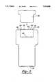
- FIG. 2is an orthogonal illustration of the appearance of the scan tool
- FIG. 3is a plan illustration of the appearance of the back of the scan tool
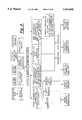
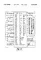
- FIG. 4is a block diagram representing the architecture of the hand held unit
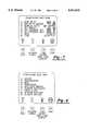
- FIG. 5is an illustration of the main menu of the hand held unit
- FIG. 6is an illustration of the hand held unit screen when selecting a vehicle system for monitoring
- FIG. 7is an illustration of the hand held unit screen when setting user options
- FIG. 8is an illustration of the main master station menu screen
- FIG. 9is a logic tree showing various features available
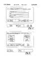
- FIG. 10is a sample diagnostic instruction screen from the master station
- FIG. 11is an illustration of a sample display screen from the master station showing technical information used during diagnostics
- FIG. 12is an illustration of the master station screen when displaying logged data
- FIG. 13is an detailed illustration of the textual data display when dynamically displaying parameters on the master station
- FIG. 14is logic tree showing the data recording and logging functions
- FIG. 15is a logic tree showing how templates are stored and retrieved
- FIG. 16is an illustration of the master station screen as a custom template is being built
- FIG. 17an illustration of the service update screen
- FIG. 18is a function diagram illustrating the different ways the hand held unit can be updated.
- the system of the presently preferred embodimentincludes the hand held unit 10 which connects to the car 12 and the master station 14 via cables 16, 18.
- the hand held unit 10has specialized hardware and software on board for communicating with the various controllers on the car.
- the hand held unit 10is capable of operating as a scan tool, volt-ohm meter, and data logging unit by itself without requiring support from the master station.
- the master station 14is connected 18 to the hand held unit 10
- the hand held unitcan serve as a smart interface between the master station 14 and the various controllers on the car 12.
- the master stationitself is capable of downloading alternative diagnostic routines to the hand held unit 10 as needed, while also providing the ability to update and/or reconfigure the internal memory of the hand held unit.
- the master stationfurther provides interactive data charting capabilities.
- the master station 14also serves as a paperless service manual, providing detailed pictorial and textural service information.
- the hand held unit 10is approximately 14 inches long, 6 inches wide, 21/2 inches tall and weighs approximately 4 lbs.
- the face of the hand held unitincludes a display screen 20 and a keypad 22.
- the display screen in this embodimentis a backlit LCD display having a resolution of 320 ⁇ 200 pixels, with an overall screen dimension of 4 inches wide by 3 inches tall.
- the screenis tilted at a slight angle to facilitate viewing from an angle, such as would occur if the unit were placed on a work table or on the car while being used.
- the key padis formed from a flexible plastic membrane with the key boundaries 23 embossed and the characters 24 printed on the surface.
- the key padincludes four function keys 26, four directional arrow keys 27 used to parse through character strings and step through logic sequences, two enter keys 28 to indicate a command is to be entered, ten alphanumeric keys 29 for entering letters, numbers and characters, and eight special function keys 30 used for responding to queries and the like.
- the key padis a membrane key pad in this embodiment because of the harsh environment in which the hand held tool operates. By utilizing a membrane, the actual key contact points are protected from contamination by dirt and moisture. Moreover, utilizing a membrane key pad helps reduce the likelihood that keystrokes are entered unintentionally.
- an expansion slot 31is adapted to receive conventional PCMCIA card memory expansion boards.
- the memory expansion cartridgesare useful when using the hand held unit as a data logger, which will be described in greater detail later.
- connection points 32-38for electrical probes, an RS-232 connection 40 for communicating with other computers and computer peripherals, a vehicle interface connection 42 and a GPIB master station interface connection 44.
- a removable cover 46protects a peripheral expansion port 48.
- the peripheral expansion portaccepts an expansion module which allows the hand held tool to be compatible with many other devices, such as a computer disk drive, a wider variety of vehicle controllers and other types of measurement tools.
- the vehicle interface connector 42is a thirty-six way connector.
- the hand held unit 10is interfaced to the vehicle 12 via the vehicle interface cable 16.
- the vehicle interface 44is adapted to work with a variety of interface cables. Specifically, six different types of cables are currently supported. All of these cables, while utilizing the same thirty-six way interface, support different communication protocols.
- an ISO 9141/CARB cableis an asynchronous full duplex serial communication link configurable to a variety of baud rates, such as 976, 7812.5, 62.5K, and 10.4K baud rates, with signal levels varying between an idle condition of twelve volts and zero volts.
- an SCI-I cableis an asynchronous duplex serial communication link configurable to baud rates such as 976, 7812.5, and 62.5K baud, with the signal levels varying from an idle of zero volts to five volts.
- Both the SCI-I and ISO 9141/CARB communication linksutilize the standard ten bit non return to zero (NRZ) data format, with one start bit, eight data bits and one stop bit.
- Yet another cablecommunicates using a contention-based, class B multiplexed bus, transferring data at 7812.5 baud via a voltage differential generated across the bus which is biased to 2.5 volts.
- the hand held tool 10must be able to recognize which cable is connected at the interface 42 and adapt its communication protocol accordingly. In this embodiment, this is accomplished by ensuring each of the unique cables has a unique resistance associated therewith. This unique resistance is measured and recognized by the hand held unit 10 so that it may identify the cable to which it is connected and adjust its communication protocol accordingly. Specifically, in this embodiment, two pins of the connector provide the resistance signal feed. The resistance signal feed is interfaced to the control logic circuitry so that the resistance may be measured and compared to predetermined values corresponding to the unique resistances for the various cables.
- the resistance values of the various cableshave been established such that, given measurement tolerances, there is no chance of overlap between the resistance values, which may otherwise cause an erroneous cable identification.
- a cable for communicating with the engine controllerhas a nominal resistance of 3,010 ohms
- a cable for communicating with the body controllerhas a nominal resistance of 14,000 ohms
- the J1962 cablehas a nominal resistance of 44200 ohms.
- the actual architecture of the hand held unit's controllercan be found in FIG. 4. As shown here, there are two microcomputers on board, an ST9 50 and an MC68332 (not shown).
- the ST9 microcomputercommercially available from S. G. Thomson of Texas, is the communications coprocessor while the MC68332 microcontroller, available from Motorola of Illinois, performs the diagnostic and data gathering features.
- the ST9 controllerhas A-D converters 52 for measuring and scaling information from the vehicle interface connector, and has addressing and data control buffers 54-60 for communicating with the MC68332 controller.
- the MC68332has interface buffers and A-D converters. Here, both regular speed and high speed A-D converters are used to ensure the data gathering process is rapid and accurate.
- the hand held unithas 4.5 megabytes of memory.
- One 250K block of memoryis the boot ROM, which can be reprogrammed, or "flashed", to alter the operation of the hand held unit.
- the boot memorycontains the operating system and device drivers used by the hand held unit.
- Another 250K block of memoryis pseudo-static memory with a ninety-six hour storage life. This memory is used for storing specialized diagnostic routines that have been downloaded to the hand held unit, and for storing customized data gathering templates.
- Another 1 Mb block of memoryis also flashable, and stores the diagnostic procedure information. This memory can be reflashed via the master station link 18 from the master station 14 or can be reflashed using a memory expansion card in one of the expansion slots 31, 48 or via the RS232 serial link 40.
- Another 1 Mb block of memoryis pseudo static memory with an eight hour life. This memory, like the ninety six hour life memory, is used to store information such as specialized diagnostic routines.
- the final 2 Mb block of memoryis RAM
- the master station connection port 44supports GPIB communication protocol between the hand held tool 10 and the master station 14.
- the hand held toolcan operate as the controller, talker or listener.
- the controller mode of operationthe hand held tool controls the operation of the master station and performs diagnostic routines by querying the vehicle controllers via the vehicle interface 42.
- the talker modethe hand held tool 10 communicates with the master station 14 by transmitting information to the master station.
- the listener modethe hand held tool receives information from the master station via the interface 44.
- the hand held unit 10is capable of functioning as a diagnostic scan tool. When in scan tool mode, the hand held unit communicates with the vehicle 12 via the communication cable 16. Depending upon the type of vehicle being diagnosed and the particular controller within the vehicle being queried, one of the six available cables, as discussed earlier, will be selected. For the purposed of this discussion, it will be assumed that the ISO 9141/CARB cable has been selected because information from a standard engine controller is desired.
- One end of the communication cable 16is connected to the hand held unit 10, while the other end of the cable is connected to the vehicle 12 at the service connector interface, usually located underneath the hood or the dashboard.
- the hand held unit 10measures the resistance of the cable 16 and determines that it is the ISO 9141/CARB cable, and configures its communication protocol accordingly.
- the hand held unit 10once connected into the vehicle communication bus via the interface, sends commands to the engine controller and receives information back. These commands are executed by the service technician by entering information in the hand held tool via the key pad.
- the technicianupon powering up the hand held unit 10, the technician is presented with a menu display 60 providing a variety of options and function keys.
- the techniciancan select any menu item 62 by pressing the corresponding number 64 or can invoke a function such as "help” 66, "screen toggle” 68, "illuminate back light display” 76 and "stop” 72 by pressing the function F1 through F4 keys 74-80, respectively.
- a functionsuch as "help” 66, "screen toggle” 68, "illuminate back light display” 76 and "stop” 72 by pressing the function F1 through F4 keys 74-80, respectively.
- providing the generic key face labels "F1" through "F4" 82-88while providing the function describer in the form of an icon located above the key allows the key pad to be freely configurable through software.
- the F4 keyneed not be assigned the function of "stop". Rather, at that stage, the key may be de-assigned, in which case no icon 66-72 would appear over it and no action would be taken in the event of that key being stroked, or the key may be reassigned, in which case a new action and associated icon can be designated.
- the ability to assign, reassign and de-assign activities to the function keysallows the scan tool to be readily configured for use with a variety of vehicles and vehicle controllers without requiring physical modification of the unit.
- the iconscan serve a dual function of being both a key identifier and an activity indicator.
- the "stop" keyserves not only to identify that the F4 key will invoke the stop function, but also serves as an operation-in-progress indicator by blinking whenever an operation is running. If the technician invokes the stop function, the icon stops blinking to indicate the operation has been stopped.
- Action taken based upon the actuation of a function key 26is immediate; that is, there is no need to press the enter key 28 to execute a function key.
- the alphanumeric keys 29are used to enter characters, the characters are not actually acted upon until the enter key 28 is pressed.
- the usercan depress the numeral one on the key pad to move the highlight curser bar to the first item.
- the usercould use the directional arrow keys 27 to scroll the highlight bar to item number one.
- the highlight baris highlighting, or pointing to, the first item, the user depresses the enter key to indicate that the first item is the desired item to be acted upon.
- accidental key strokesdo not result in unintended activity.
- the key strokecan simply be overridden by later key strokes or the character typed over by backing the curser over the character and typing a new character.
- the usercan step the hand held unit 10 to accomplish different procedures.
- the next screen the user is presented withis the system selection screen, shown in FIG. 6.
- the usercan decide which controller is to be queried.
- the useris presented with a variety of options for querying the controller as to stored diagnostic codes and monitoring operational parameters. For example, most engine controller store codes in the event that an operational problem is detected.
- the error code stored by the engine controllerwill be assumed to be an error code associated with an O2 sensor reading below the required threshold.
- the techniciancan send commands to the engine controller to have the engine controller relay its fault code information to the hand held unit for display.
- such a commandwould result in the display providing a reference such as "O2 sensor threshold low".
- the techniciancan then decide how he would like to isolate the problem. If desired, he can connect the hand held unit to the master station to progress through a diagnostic routine, wherein the technician is stepped through a series of actions which help the technician identify and isolate the cause of the problem. In this instance, the fact that the O2 sensor reading is abnormally low does not necessarily mean that the O2 sensor is bad. Therefore, the diagnostic actions prescribed in the diagnostic steps would walk the technician through the fault diagnosis procedure to aid him in isolating the problem. The manner in which the hand held unit and the master station cooperate when running diagnostics will be described in greater detail later.
- the hand held unitis provided with two sets of probe inputs 32-38 to allow measurements at two test points. Operation as a DMM can be invoked two different ways. First, the technician may be requested to perform an electrical reading as part of one of the diagnostic steps. For example, using the O2 sensor hypothetical, one of the diagnostic steps may require the technician to measure the resistance of the O2 sensor. By placing the probes at the appropriate point on the O2 sensor, the hand held unit will measure the resistance of the sensor and display that resistance reading on the screen.
- DMMdigital multi meter
- integrating the DMM mode into the scan tool modeallows the measured reading to serve as the technician's response to the scan tool's query.
- the techniciancan invoke DMM mode by simply pressing the DMM key on the key pad. Invoking DMM mode simply suspends whatever operation the scan tool is currently engaged in for being resumed at a later time. Specifically, a split window is opened on the display screen: the top half of the window shows the DMM mode, while the bottom half of the screen shows the suspended operation.
- the techniciancan toggle between DMM mode and the suspended operation by using the F2 "toggle up/down" key. When the technician toggles down to the operation window, the operation is resumed and the DMM mode is suspended. To completely exit from DMM mode, the technician simply depresses the DMM key again.
- the techniciancan be performing a diagnostic procedure on one vehicle and can interrupt that procedure to perform an electrical reading on a separate vehicle without requiring the technician to terminate the diagnostic procedure on the first vehicle. This feature further enhances the technician's ability to operate in an efficient manner.
- the techniciancan perform voltage differential tests quickly and easily. For example, to measure the voltage drop across an element using conventional means, the technician would be required to use two separate meters and perform two separate readings, subtracting one reading from the other to obtain the difference.
- the techniciancan simply attach each set of probes across the element in question and the hand held unit displays the voltages on the screen.
- a further feature of the DMM modeis that each set of probes can be operated independently of the other. That is, one set of probes can be used to measure current draw while the other set of probes can be used to measure voltage drop. Again, the technician's efficiency is greatly improved by this feature. Rather than requiring the technician to use separate meters to perform different types of readings, or requiring the technician to perform these different readings sequentially, the technician can simply attach the probes to the items in question and perform these different types of readings simultaneously.
- a further feature of the DMM modeis that single probe measurements are possible. This feature is especially important when attempting to measure electrical characteristics of devices in hard to reach locations. Because the hand held unit can be connected into the vehicle communication bus via the communication link, the hand held unit is provided with system and chassis ground via the communication link, obviating the need to provide a separate measurement ground via the test probe. Therefore, using only one lead of the test probe, voltage and current measurements can be obtained, using the signal or chassis ground provided via the communication link as the measurement ground.
- the hand held unitis also capable of downloading information to the vehicle controllers for the purpose of updating these controllers.
- controllersutilize a combination of ROM and RAM.
- the ROMcontains the control algorithm and calibration parameters, while the RAM contains operational parameters.
- the ROMwas hard coded, that is, the ROM was fixed and unchangeable.
- RAMwas volatile and any information stored in RAM would be lost if the controller power supply was interrupted.
- automotive controllersrely upon a combination of hard coded and erasable ROM in addition to RAM.
- the erasable ROMusually contains information such as calibration parameters.
- the hand held unithas the capability to write, or "flash", erasable memory on the vehicle controllers. To accomplish this, the hand held unit has, stored in its own internal memory, the new information to be downloaded to the vehicle controller. The technician enters the flash programming mode by selecting the appropriate menu item from the display screen. Once this mode is selected, the hand held unit sends a control message to the controller to inquire as to the version and model number of the controller's memory.
- the hand held unitUpon receiving the response from the vehicle controller, the hand held unit determines whether or not the vehicle controller's memory needs to be updated. If the memory does need to be updated, the technician is presented with a screen indicating so and asking the technician whether or not he wishes to proceed. Assuming the technician has indicated his desire to proceed by pressing the yes key, the hand held unit sends the commands to the vehicle controller necessary to reconfigure the programmable ROM to reflect the new calibration values. The process of sending the appropriate commands and calibration data to a vehicle controller and verifying that the information has been correctly received and stored is well within the grasp of one of ordinary skill in the art, and therefore will not be described in detail herein. Once the commanding, writing and verification process has been completed, the hand held unit displays to the technician whether or not the vehicle controller update procedure has been successful.
- the hand held unitis also capable of recording service history information on the vehicle controllers. Similar to the process of updating calibration information, the hand held unit can send commands to the vehicle controller to store information regarding service procedures. For example, when in the scan tool mode, the technician is reading fault code information from the vehicle controller in an attempt to diagnose and isolate the cause of the fault condition. Once the technician has successfully isolated and remedied the problem, the service history recording mode of the hand held unit allows the technician to erase the fault code from the vehicle controller's memory and store codes indicating what procedures were performed and when. Such information proves very useful during later diagnostic procedures when attempting to isolate new fault conditions, because actions taken by service personnel during previous service visits often affect the manner in which new problems are diagnosed.
- the techniciancould indicate that, using the hypothetical O2 sensor situation, the low O2 sensor reading problem was cured by reseating the O2 sensor connector.
- the stored service history informationcan be used during a diagnosis procedure to direct the technician to check the connection to see if the connector simply needs to be replaced.
- the storing of service history information in the vehicle controller's memorywould be valuable, and that the type of information stored can be customized to suit the specific needs of the situation.
- the hand held unitcan monitor hundreds of different parameters on the vehicle.
- the engine controllercan provide information regarding fuel-air ratio
- the transmission controllercan provide transmission oil temperature
- the anti-lock brake controllercan provide wheel speeds
- the body controllercan provide information on whether lamps are burned out or doors are opened.
- the hand held toolcan gather, from a variety of sources, information necessary to diagnose problems.
- the service techniciandesires to monitor information from these various sources simultaneously during service and maintenance routines. Therefore, the hand held unit has been provided with the capability for the technician to develop customized reading templates for gathering such diverse information quickly and efficiently.
- the techniciansimply selects the menu item for using and storing templates. By selecting this item, the hand held unit is placed in a programming mode of sorts.
- the techniciancan retrieve predefined templates from memory and can store and retrieve customized templates as well.
- the techniciansimply selects that template from the selection list.
- a predetermined templatemay provide information as to whether or not the brake pedal is depressed and whether or not the brake lamps are illuminated for the purpose of diagnosing wiring or lamp failures. While such a predetermined template is usually retrieved automatically during the process of performing a diagnostic routine in the scan tool mode, the technician can selectively retrieve predetermined templates for use outside of the scan tool mode.
- the technicianmay find a need to define his own customized templates. To do this, the technician enters the customization mode and simply selects from lists those parameters he wishes to display in this customized template. After selecting the items and building the template, the technician can store this customized template in the memory of the hand held unit by selecting the store option and entering an appropriate template identifier string. For example, the technician may simply want to store the template by identifying it as "CUSTOM 1", or may wish to identify the template by his name, the date, or other such unique identifiers. To enter characters for the template identifier string, the technician simply presses the shift key while simultaneously pressing one of the alphanumeric keys to access letters rather than numerals.
- the technicianwould hold the shift key down while depressing the 1/ABC key three times: the first time he pressed the key the letter A would appear, the second time the letter B would appear, and the third time the letter C would appear.
- the character sequencesimply restarts. Therefore, upon the forth time, the letter A would again reappear.
- the technicianwould depress the right arrow key to parse over to the next character position and would depress the shift key while simultaneously depressing the 7/STU key three times. Once the identifier string has been built, the technician can enter that name by simply depressing the enter key.
- the hand held toolstores the customized template in the ninety-six hour memory according to the identifier string.
- the techniciancan direct the hand held unit to store the template on a memory cartridge, or can upload the template to the master station for storage on its internal hard drive or on a floppy disk. During later operations, the technician can retrieve this customized template by selecting it from the list of available templates.
- Another important feature of the hand held unitis its ability to function as a data logger. Often, when conducting diagnostic procedures, the technician will be unable to recreate in the garage the problem of which the customer is complaining. Rather, many problems often manifest themselves as the car is driving over bumps or underneath power lines--conditions which cannot be recreated in a garage. Therefore, the technician can use the hand held tool to monitor vehicle parameters as the vehicle is being driven. By monitoring vehicle parameters on a real time basis, the technician can obtain a better understanding of the conditions which may be causing the problem.
- the technicianselects the data logging option from the menu.
- the techniciancan select a predefined data logger template or can establish his own customized template in a manner similar to that which was previously described.
- the templatedefines which variables are to be monitored.
- the hand held unit's internal memorysamples these parameters and stores them for later retrieval.
- the logged datais stored in memory using a shift register concept. That is, as new data is logged, older data is overwritten. Therefore, in the hand held unit's memory, the logging information stored represents a snapshot, or window, of information.
- the techniciancan que the hand held unit to "freeze" a window of information. This is accomplished by the technician triggering the read-hold key on the keypad.
- the hand held unitstores a window of information in memory such that the values of the monitored parameters around the time of the trigger are stored. In this way, the hand held unit stores the parameters so that the behavior of the monitored parameters before, during and after the trigger can be retrieved for later inquiry.
- Such informationoften proves valuable when diagnosing problems which manifest themselves only while the vehicle is being driven.
- the hand held unithas expansion ports for receiving expansion modules.
- These modulescan take a variety of forms, and can include not only additional memory but interface circuitry for allowing the hand held unit to communicate with different devices.
- Providing for the expansion ports and expansion module capabilitiesallows the hand held unit to "grow" as technology evolves without requiring the entire scan tool to be traded in or reconfigured.
- new featurescan be incorporated into the service tool system more economically, because only the circuitry for the new feature need be designed--the hand held unit itself does not require rebuilding or redesign.
- an expansion module for performing radio frequency measurementsmay become available. The expansion module would contain the circuitry needed to perform such a specialized measurement and would interface to the hand held unit via the expansion port.
- operating routinescan be downloaded into temporary memory or the memory of the hand held unit could be reconfigured (as will be described in greater detail in the "service tool update” section) to provide the instruction sets necessary to execute such features.
- the techniciancan also customize the manner in which information is presented to him. For example, he can change the display units from U.S. to metric and can change the date and time. As before, items from the menu are selected using the alphanumeric and/or arrow keys. Also, the hand held unit has on-board help procedures to aid the technician in the use of the hand held unit. Help can be invoked one of two ways: first, by selecting the "how to use” unit item from the main menu as shown in FIG. 5, or by pressing the "help" key at any time during operations. Invoking help by pressing the "help" key during operations presents the technician with context-sensitive help information.
- invoking helpwill provide the technician with help screens related to DVOM mode.
- the techniciancan view help topics related to any aspect of the hand held unit, by simply paging forward and backward and selecting new help topics.
- the hand held unitcan be connected to other devices such as a modem or a printer.
- the master station 14is designed to work in cooperation with the hand held unit in performing sophisticated diagnostic procedures and the like, and can operate independently of the hand held unit as a reference resource for the service technician.
- the master stationitself is approximately 41/2 feet tall, with a base dimension of approximately 36 inches by 24 inches.
- the heart of the master stationis an IBM-compatible computer with an internal hard drive.
- the master stationalso includes a 19 inch monochrome video monitor 100 for graphics display, a keyboard 102, a floppy disk drive and CD-ROM drives 104, and communication cables 18.
- the master station cart 106has casters 108 at the base for allowing the station to be rolled from place to place.
- the internal memory of the computercontains the master station operating system, while the CD-ROM drives are used to store service and diagnostic information and the like.
- the floppy disk driveaccepts standard 31/2 inch disks and is used for things such as swapping information between stations and for performing backups and storing seldom used information, while the larger capacity hard drive is used for storing information such as diagnostic results and customized test procedures.
- the master stationcan operate alone or in conjunction with the hand held unit 10. Specifically, regardless of whether the master station 14 is connected to the hand held unit, the master station is capable of operating as a technical information library, parts catalog and host update link. However, when connected to the hand held unit, the master station is also capable of acting as a data recorder, diagnostic station, and hand held unit update host.
- the master stationbesides having a GPIB interface for communicating with the hand held unit, also has an RS-232 interface for communicating with other service tools. In this embodiment, earlier generation hand held units communicated only via RS-232. Therefore, the master station of the present invention can communicate with older units via the RS-232 while also communicating with the hand held unit via the GPIB link.
- the user interfaceappears similar to that of FIG. 8.
- the user interfaceis both graphic and textural in nature, where the highlight bar can be moved between items to select the desired action.
- the techniciancan use the keys of the keyboard or, if the hand held unit is connected to the master station, can use the key pad on the hand held unit. Similar to selecting items on the hand held unit, the technician can parse through screens using directional arrow and paging keys. Also, as was the case with the hand held unit, the technician can "backup" through procedures in the event he changes his mind about the course of the action selected.
- the master stationobviates the need for printed paper manuals and service bulletins through its technical information library mode.
- the techniciancan access service manuals and service bulletins, which are stored on the CD-ROM's, for display on the monitor.
- This modehas several benefits.
- Firstis the advantage of obviating the need for paper manuals and service bulletins, which often become torn, soiled and lost over time.
- the informationis stored electronically and retrieved only as needed, there is no need to have book shelves for storing these items.
- new "pages"can be added electronically by updating the CD-ROM without requiring the technician to physically insert pages into a printed manual.
- Updating technical informationcan also be accomplished by supplementing the information on the CD-ROM's through information stored on floppy disks, as well as information available via telecommunication download links, such as modems.
- the master stationcan be connected to any conventional phone line for communicating with a remote host computer for downloading update information. Once the information is downloaded into the master station, the updated information can be stored in the internal memory of the master station or on a floppy disk. By allowing updated information to be provided via these different methods, the master station technical information library can be easily maintained in an up to date state.
- the master station technical information libraryis that, because the information is stored electronically, it can be sorted and filtered before being presented to the technician. That is, the technician can indicate that he is looking for information related to a certain vehicle or a certain component, and the master station can retrieve those portions of the technical information library relevant to the technician's query, without requiring the technician to leaf through otherwise irrelevant information. This has a great advantage to printed media, since the technician must physically parse through the pages to find the relevant information when using printed manuals. The technician can also search for information by the vehicle information number (VIN) in a similar matter.
- VINvehicle information number
- the master stationalso includes an on-line parts catalog. Using this feature, the technician can view various components of the automobile, and can place orders for parts that the service station may not carry in stock. When connected into a common phone line, the master station can automatically place orders for these parts using an electronic ordering system.
- the master stationWhen connected to the hand held unit, the master station augments the hand held unit's diagnostic capabilities. These features are represented as a logic tree in FIG. 9. Because the hand held unit, by its nature, has only a limited amount of memory available, the master station is used to store all diagnostic procedures for all the various controllers and vehicles which are supported by the service station or dealership. As the technician performs a diagnostic procedure on the vehicle, the hand held unit will request the master station to send it additional diagnostic information in the event the hand held unit's memory does not contain the required diagnostic procedures. This information is then downloaded to the hand held unit via the communication link 18 and stored in the eight hour memory.
- the information downloaded from the master station to the hand held unitrequires a substantial amount of memory.
- the hand held unitpurges from its memory those routines and information used the least in favor of storing the newly downloaded information.
- This schemeis often referred to as a "least recently used” memory management scheme, and allows information which is rarely used or which have never been used to be removed from memory, rather than a "first in, first out” scheme which automatically removes the longest stored, or oldest, information from memory simply because it has been there longer.
- the display of the master stationdisplays the graphical and textural reference from the technical information library which corresponds to the diagnostic step being performed. For example, as shown in FIGS. 10 and 11, the master station display informs the technician of the action required for the particular diagnostic step, while presenting a graphic representation of the vehicle or systems in question.
- the master stationdisplays these graphical representations in conjunction with the instruction text for each of the diagnostic steps.
- the technicianstill could performs diagnostic tests without linking the hand held unit to the master station. If he chose to operate in this manner, he would refer to a printed service manual, or would invoke diagnostic mode on the master station without linking the hand held unit, and he would manually page through the diagnostic procedure step by step. Thus, the technician would have to refer to the diagnostic procedure for the required action, and would then use the hand held unit to gather measurements required for that particular step. Once he completed that step, he would flip to the next step and perform the required action.
- the technicianis relieved of having to manually parse through the test procedure.
- the master stationdisplays test results, just as the hand held unit would display test results, based upon the diagnostic procedure being performed.
- the hand held unitactually controls the progress of the diagnostic routine. Any entries on the key pad are sent from the hand held unit to the master station and back from the master station to the key pad as a synchronizing handshake. Any entries on the keyboard of the master station are sent from the master station to the hand held unit, which actually acts upon the command.
- the diagnostic routinesare actually tokenized routines which are interpreted by the hand held unit's MC-68332 interpreter. This is in contrast to diagnostic routines of other commercially available systems, which are actually coded programs.
- new diagnostic routinescan be "written", or built, using a flow chart form of representation. Specifically, any common computer can be used to built the diagnostic routine as a series of action blocks linked by logic flow paths. These routines are then compiled by the master station as tokenized routines, which are downloaded to the hand held unit for interpretation and execution.
- the support personnel writing diagnostic proceduresneed not be sophisticated programmers; rather, the support personnel simply need to be able to visually describe what steps are to be taken and in what order, since the master station and hand held unit are designed to use these forms of routines.
- each diagnostic routinecan be thought of simply as a series of steps, where the preceding step leads to the following step. Where there is a choice of steps, the preceding step simply leads to one of the alternative step based upon the technician's choice of action.
- the technicianis required to perform certain tasks, such as checking to see if a connection is secure or performing a voltage reading.
- the techniciancan respond to queries from the system by entering "yes" or "no", or by entering numeric or alphabetic information via the keypad.
- the systemmay require the technician to first check to see of the connection is secure. Once he has checked the connection, the technician responds to the system by pressing the yes or no key accordingly.
- the systemmay require the technician to measure the resistance of the O2 sensor. By placing the probes of the hand held unit on the O2 sensor connection points, the hand held unit measures the resistance and displays the reading. The technician can then indicate the reading appears to be accurate by pressing the yes or no key.
- the various diagnostic stepscan be though of as "pages", where paging down involves moving on to the next step, and paging back involves back tracking to the previous step in the sequence.
- the techniciancan control his progress through the diagnostic steps by using the page up and page down keys.
- the hand held unitprovides greater flexibility for the technician in diagnosing the problem. For example, after progressing through the diagnostic steps for a while, the technician may determine that he is proceeding down a less than fruitful course of action. In such an instance, the technician can use the page up key to back track through the diagnostic procedures. This allows the technician to back track, for example, and modify his response to previous queries or select a different course of action when he was presented with several choices.
- the master stationcan serve as a data recorder and display unit.
- the hand held unitcan serve as a stand alone data logger for capturing vehicle information as a vehicle is being driven. To display this information, the hand held unit is connected to the master station and the display stored data option is selected. As shown in FIG. 12, the captured data is displayed graphically as well as numerically. Moreover, in the event that many parameters have been monitored, certain of the parameters can be displayed graphically while the remainder of the parameters are displayed textually. Similar to the concept of using templates for selecting the data to be logged, the master station has templates that define which variables are displayed graphically as charts and which variables are displayed simply textually as numbers or as logic states.
- the techniciancan retrieve predetermined templates or can define customized templates of his own. Since the data displayed represents a snapshot in time, the display cursor, represented as a dashed line 120 on the data graphs, indicates the point in time for which the variables are being displayed. Thus, the variables being displayed textually represent the value of those variables corresponding to the point in time where the cursor lies. The cursor position is represented as a relative time value from the beginning of the window, and is useful when attempting to determine the elapsed time between events or occurrences. It can be appreciated that providing data logging and displaying capabilities with the hand held unit and master station allows the technician to gather a wealth of information without having to rely upon additional, costly test equipment.
- the hand held unit and master stationcooperate so that operating parameters can be displayed dynamically.
- the master stationdisplays some of the variables as charts and other of the variables textually, depending upon the template selected.
- many more parameterscan be monitored than would be possible using the data logger alone as shown in FIG. 13. That is because the variables are being displayed dynamically, rather than being stored, and the amount of information gathered need not be limited by the amount of on board memory available in the hand held unit.
- the dynamically displayed datacan be logged in the master station and stored in the master station's internal memory or on a floppy disk for later reference.
- the master stationhas capabilities for creating customized templates which can be stored using string identifiers and retrieved for later use.
- the master stationcan also reprogram the hand held unit in a manner similar to the way the hand held unit can reprogram controllers on the vehicle.
- the techniciancan select the update scan tool option from the menu.
- the hand held unit's memorycan be reconfigured accordingly.
- the basic diagnostic procedure stored in the hand held unitcan be updated, but the actual boot memory of the hand held unit can be modified as well.
- the scan tool update modethe basic operation of the hand held unit can be reconfigured as needed. This allows the hand held unit to be updated quickly and easily as needed, without requiring the technician to trade in scan tools or physically modify its configuration.
- the hand held unitcan also be reconfigured without the master station by connecting it to a programming device via the RS-232 connection. Selective memory updates can be accomplished by employing memory cards used in the expansion slots.
- the technicianconnects the hand held unit to the vehicle so that he may retrieve information from the engine controller.
- the technicianselects the appropriate cable, and the hand held unit identifies the cable and modifies its communication protocol accordingly.
- the technicianselects the vehicle diagnosis option from the main menu and selects engine controller from the sub-menu.
- the hand held toolqueries the engine controller and informs the technician that there is a fault code for lean air fuel ratio.
- the technicianthen begins checking the various sub-components on the engine to locate the cause of the fault.
- the technicianuses the hand held unit to measure the resistance of the MAP sensor.
- the technicianinserts the voltage probes into the hand held unit and places the other end of the probes across the MAP sensor.
- the resistance of the MAP sensoris read and displayed for the technician and the fault diagnosis procedure continues.
- the service managerWhile the technician is diagnosing the problems on the customer's vehicle, the service manager interrupts the technician and ask the him to perform a voltage reading across an old car battery which has been in storage. Without having to disconnect the hand held unit from the car, the technician selects the DVOM mode on the hand held unit and measures the voltage across the battery as requested. The hand held unit displays the voltage reading for the technician. Once the technician is done with his side task, he simply presses the key pad to resume the fault diagnosis procedure.
- the technicianAfter having proceeded through the fault diagnosis procedure without yet locating the problem, the technician turns to the master station to access the technician information library for more assistance. Using the keyboard on the master station, the technician enters the vehicle type and model year to see if a service bulletin has been issued regarding this problem.
- the master stationsearches its CD-ROM data base for a relevant bulletin and presents the information to the technician on the monitor. In this example, the bulletin informs the technician that problems such as this have indeed been experienced in the field, and a new diagnostic procedure has been provided.
- the technicianconnects the hand held unit to the master station via the communication link and, using the keyboard, request the master station to download the new diagnostic procedure to the hand held unit.
- the master stationrelays the information to the hand held unit, and the new diagnostic procedure is stored in the hand held unit's eight hour memory. The technician then begins executing the new diagnostic procedure.
- the master stationSince the master station is connected to the hand held unit while the technician is executing the diagnostic procedure, the master station displays for the technician information such as the particular step required and the appearance of the components in question. As part of the diagnostic procedure, the technician is requested to turn on the engine and idle it at 2,300 rpm. The master station recalls a predetermined template for displaying the dynamic data. The technician enters the vehicle and starts the engine, monitoring the engine rpm as displayed on the master station monitor. The master station monitor displays not only the engine rpm as a number along the right hand column, but also displays rpm, MAP sensor voltage, fuel rate, and throttle position as charts.
- FIG. 14is a logic tree which shows the organization of the menu selection process used by the technician. He then looks through the predefined templates to see if there is one that suits his needs. Finding there is not a template to his liking, the technician selects the menu screen for building templates, as shown logically in FIG. 15. Once in the template building screen, the technician moves the highlight bar from item to item, selecting those he wishes to display during the dynamic data display operation. As shown in FIG. 14
- the technicianhas selected some very specialized parameters such as cam shaft position and crankshaft position, because he thinks there is a problem with the timing belt alignment.
- the dynamic data display on the master stationpresents the monitored parameters to the technician as a combination of graphs and numbers.
- the techniciandecides to use the data logger as he drives the car around the service station's parking lot.
- the techniciandisconnects the hand held unit from the master station but leaves it connected to the car as he drives the car around. Bringing the car to a stop and beginning to accelerate, the car goes over a bump and the technician experiences a loss of engine power.
- the technicianpresses the "read hold" key on the hand held unit's keypad to store this window of information. He drives the car back to the garage, disconnects the hand held unit and walks over to the master station, which has been since rolled to the other side of the garage by another technician. Reconnecting the hand held unit to the master station, the operational parameters are displayed on the monitor for viewing.
- the information provided to the technicianallows him to diagnose the fault: fuel flow rate dropped to zero when the lag was experienced, and the fuel pump voltage dropped below the minimum threshold a few seconds prior to the fuel lag.
- fuel flow rate dropped to zero when the lag was experiencedthe fuel pump voltage dropped below the minimum threshold a few seconds prior to the fuel lag.
- the technicianfinds that the power lead has become corroded and needs to be cleaned. He cleans the connection and reseats the connector.
- the technicianthen updates the engine computer to erase the fuel error air fault flag and enter the service information. He reconnects the hand held unit to the vehicle, and clears the codes. Next, as shown in FIG. 17, he enters his ID number, the VIN number, the service order number and the mileage in hand held unit and flash programs the information into the engine controller's service log memory. Before letting the car be released to the customer, the technician checks to see if there are any service bulletins indicating an interim calibration update has been released. Checking the technical library, he learns that there has been a new set of anti-lock calibrations released. The technician places a memory module with the new calibrations into the expansion slot of the hand held unit. As shown in FIG.
- the techniciancan load update calibrations into the hand held unit using a memory card or the master station.
- the technicianqueries the car's antilock controller to see if it has the latest set of calibrations.
- the controllerresponds that it currently it running "version 3.01b" calibrations.
- the hand held unitindicates to the technician that there are newer calibrations in the memory card, and asks him if he would like to proceed with downloading these new calibrations to the anti-lock controller. He responds "yes", and the hand held tool programs the anti-lock controller's flash memory with the new calibrations.
- the controllersends a message to the hand held tool, which is displayed for the technician, indicating the update was successful.
- the service managernext asks the technician to take an inventory of the stock room and order sufficient supplies for the next two weeks. After checking the inventory, the technician goes to the master station and places an order for air filters using the telephone link to the central warehouse from the on-line parts catalog menu. He then tells the manager that the order has been placed and the parts are scheduled to arrive next Tuesday.
Landscapes
- Engineering & Computer Science (AREA)
- Transportation (AREA)
- Mechanical Engineering (AREA)
- Physics & Mathematics (AREA)
- General Physics & Mathematics (AREA)
- Vehicle Cleaning, Maintenance, Repair, Refitting, And Outriggers (AREA)
Abstract
Description
Claims (8)
Priority Applications (2)
| Application Number | Priority Date | Filing Date | Title |
|---|---|---|---|
| US08/083,050US5541840A (en) | 1993-06-25 | 1993-06-25 | Hand held automotive diagnostic service tool |
| US08/431,130US6181992B1 (en) | 1993-06-25 | 1995-04-28 | Automotive diagnostic service tool with hand held tool and master controller |
Applications Claiming Priority (1)
| Application Number | Priority Date | Filing Date | Title |
|---|---|---|---|
| US08/083,050US5541840A (en) | 1993-06-25 | 1993-06-25 | Hand held automotive diagnostic service tool |
Related Child Applications (1)
| Application Number | Title | Priority Date | Filing Date |
|---|---|---|---|
| US08/431,130DivisionUS6181992B1 (en) | 1993-06-25 | 1995-04-28 | Automotive diagnostic service tool with hand held tool and master controller |
Publications (1)
| Publication Number | Publication Date |
|---|---|
| US5541840Atrue US5541840A (en) | 1996-07-30 |
Family
ID=22175858
Family Applications (2)
| Application Number | Title | Priority Date | Filing Date |
|---|---|---|---|
| US08/083,050Expired - LifetimeUS5541840A (en) | 1993-06-25 | 1993-06-25 | Hand held automotive diagnostic service tool |
| US08/431,130Expired - LifetimeUS6181992B1 (en) | 1993-06-25 | 1995-04-28 | Automotive diagnostic service tool with hand held tool and master controller |
Family Applications After (1)
| Application Number | Title | Priority Date | Filing Date |
|---|---|---|---|
| US08/431,130Expired - LifetimeUS6181992B1 (en) | 1993-06-25 | 1995-04-28 | Automotive diagnostic service tool with hand held tool and master controller |
Country Status (1)
| Country | Link |
|---|---|
| US (2) | US5541840A (en) |
Cited By (248)
| Publication number | Priority date | Publication date | Assignee | Title |
|---|---|---|---|---|
| US5644782A (en)* | 1994-10-17 | 1997-07-01 | Motorola, Inc. | System with virtual update capable read-only memory |
| US5646865A (en)* | 1994-10-27 | 1997-07-08 | General Motors Corporation | Automotive diagnostic communications |
| US5737711A (en)* | 1994-11-09 | 1998-04-07 | Fuji Jukogyo Kabuishiki Kaisha | Diagnosis system for motor vehicle |
| US5758300A (en)* | 1994-06-24 | 1998-05-26 | Fuji Jukogyo Kabushiki Kaisha | Diagnosis system for motor vehicles and the method thereof |
| US5775783A (en)* | 1995-07-28 | 1998-07-07 | Daewoo Electronics Co., Ltd. | Anti-lock braking system capable of recording the operating conditions of elements thereof and recording method therefor |
| US5781871A (en)* | 1994-11-18 | 1998-07-14 | Robert Bosch Gmbh | Method of determining diagnostic threshold values for a particular motor vehicle type and electronic computing unit for a motor vehicle |
| EP0884223A1 (en)* | 1997-06-13 | 1998-12-16 | Renault | Communication device and procedure for a vehicle diagnosic apparatus |
| US5864783A (en)* | 1997-04-04 | 1999-01-26 | Sno-Way International | Apparatus for testing snow removal equipment |
| US5884202A (en)* | 1995-07-20 | 1999-03-16 | Hewlett-Packard Company | Modular wireless diagnostic test and information system |
| US5916286A (en)* | 1995-09-15 | 1999-06-29 | Seashore; Jay E. | Portable automobile diagnostic tool |
| US5916287A (en)* | 1996-09-30 | 1999-06-29 | Hewlett-Packard Company | Modular automotive diagnostic, test and information system |
| US5935180A (en)* | 1997-06-30 | 1999-08-10 | Chrysler Corporation | Electrical test system for vehicle manufacturing quality assurance |
| US5938716A (en)* | 1997-09-08 | 1999-08-17 | Cummins Engine Company, Inc. | System for customizing vehicle engine control computer operation |
| WO1999023451A3 (en)* | 1997-10-31 | 1999-08-26 | Snap On Tech Inc | Computerized automotive service system |
| WO1999043525A1 (en)* | 1998-02-27 | 1999-09-02 | Alliedsignal Inc. | A diagnostic communication interface unit for an adaptive braking system |
| US5950144A (en)* | 1997-06-30 | 1999-09-07 | Chrysler Corporation | Method for data transfer in vehicle electrical test system |
| US5950149A (en)* | 1997-06-30 | 1999-09-07 | Chrysler Corporation | Method for testing vehicle electrical system during manufacturing |
| WO1999049620A1 (en)* | 1998-03-20 | 1999-09-30 | Motorola Inc. | Method for a vehicular gateway to transport information, including a method for programming the gateway |
| US5982995A (en)* | 1996-11-04 | 1999-11-09 | Xerox Corporation | Method for logging data in an electrophotographic printing machine |
| US6021366A (en)* | 1997-06-30 | 2000-02-01 | Chrysler Corporation | Method for testing electrical wiring buck of vehicle |
| GB2340950A (en)* | 1998-08-28 | 2000-03-01 | Snap On Equipment | Automotive testing |
| US6073063A (en)* | 1997-02-06 | 2000-06-06 | Ford Global Technologies, Inc. | Automotive data recording device |
| US6097998A (en)* | 1998-09-11 | 2000-08-01 | Alliedsignal Truck Brake Systems Co. | Method and apparatus for graphically monitoring and controlling a vehicle anti-lock braking system |
| US6104988A (en)* | 1998-08-27 | 2000-08-15 | Automotive Electronics, Inc. | Electronic control assembly testing system |
| US6105003A (en)* | 1994-08-05 | 2000-08-15 | Fujitsu Limited | Customer data processing system provided in a showroom |
| FR2791432A1 (en)* | 1999-03-26 | 2000-09-29 | Peugeot Citroen Automobiles Sa | METHOD FOR MONITORING THE ANTI-LOCK FUNCTION OF MOTOR VEHICLE WHEELS AND MONITORING ARRANGEMENT FOR CARRYING OUT SAID METHOD |
| US6141608A (en)* | 1997-10-28 | 2000-10-31 | Snap-On Tools Company | System for dynamic diagnosis of apparatus operating conditions |
| WO2000068660A1 (en)* | 1999-05-11 | 2000-11-16 | Robert Bosch Gmbh | Diagnostic test device for motor vehicles which comprises a portable testing apparatus |
| GB2350443A (en)* | 1999-05-22 | 2000-11-29 | Luk Getriebe Systeme Gmbh | Diagnostic system, particularly for motor vehicles |
| US6169943B1 (en)* | 1999-07-14 | 2001-01-02 | Eaton Corporation | Motor vehicle diagnostic system using hand-held remote control |
| US6189057B1 (en) | 1998-09-14 | 2001-02-13 | Chrysler Corporation | Motor vehicle accessory interface for transferring serial data with and supplying DC power to external accessory device |
| GB2353601A (en)* | 1998-08-28 | 2001-02-28 | Snap On Equipment Ltd | Automotive testing |
| US6208948B1 (en)* | 1997-06-19 | 2001-03-27 | Daimlerchrysler Ag | Computer-assisted diagnostic device and diagnostic process for electronically controlled systems |
| US6212449B1 (en)* | 1997-09-30 | 2001-04-03 | Crown Equipment Corporation | Diagnosing malfunctions in materials handling vehicles |
| US6225898B1 (en)* | 1998-05-13 | 2001-05-01 | Denso Corporation | Vehicle diagnosis system having transponder for OBD III |
| USD442101S1 (en) | 2000-05-17 | 2001-05-15 | Spx Corporation | Digital automobile tester |
| US6282469B1 (en)* | 1998-07-22 | 2001-08-28 | Snap-On Technologies, Inc. | Computerized automotive service equipment using multipoint serial link data transmission protocols |
| US6311162B1 (en) | 1998-07-25 | 2001-10-30 | Ernst F. Reichwein | Interactive symptomatic recording system and methods |
| WO2001082039A1 (en)* | 2000-04-25 | 2001-11-01 | Snap-On Technologies, Inc. | Single-hand held diagnostic display unit |
| US20020032491A1 (en)* | 2000-09-12 | 2002-03-14 | Fumihiro Imamura | Remote control of laundry appliance |
| US6370454B1 (en)* | 2000-02-25 | 2002-04-09 | Edwin S. Moore Iii | Apparatus and method for monitoring and maintaining mechanized equipment |
| US6389561B1 (en)* | 1995-02-01 | 2002-05-14 | Favoweb Ltd. | System and method for failure reporting and collection |
| US6405117B1 (en)* | 2001-06-21 | 2002-06-11 | General Motors Corporation | Method of diagnosing a vehicle brake system using brake pedal position and vehicle deceleration |
| US20020073000A1 (en)* | 2000-05-05 | 2002-06-13 | Mike Sage | System and method for implementing a wireless network in a service center for generating a repair order |
| US20020077779A1 (en)* | 2000-10-17 | 2002-06-20 | Spx Corporation | Apparatus and method for displaying diagnostic values |
| US6438511B1 (en)* | 2000-11-14 | 2002-08-20 | Detroit Diesel Corporation | Population data acquisition system |
| US6466861B2 (en) | 2001-02-20 | 2002-10-15 | Cummins, Inc. | Dynamic service tool for an engine control module |
| US6484127B1 (en) | 2000-11-27 | 2002-11-19 | Volvo Trucks North America, Inc. | Oil maintenance indicator |
| US6496014B1 (en)* | 2000-07-18 | 2002-12-17 | Agilent Technologies, Inc. | Cable tester error compensation method and apparatus |
| US20020193925A1 (en)* | 2001-06-15 | 2002-12-19 | Travis Funkhouser | Auto diagnostic method and device |
| US20020198997A1 (en)* | 2001-06-20 | 2002-12-26 | Linthicum Steven Eric | System and method for on board maintenance instructions and records |
| US6501393B1 (en) | 1999-09-27 | 2002-12-31 | Time Domain Corporation | System and method for using impulse radio technology to track and monitor vehicles |
| US20030052801A1 (en)* | 2001-08-28 | 2003-03-20 | Mcclure Robert | ASCII gateway to in-vehicle networks |
| US20030093522A1 (en)* | 1995-06-05 | 2003-05-15 | Tetsuro Motoyama | Method and system for diagnosis or control of machines |
| US6571191B1 (en) | 1998-10-27 | 2003-05-27 | Cummins, Inc. | Method and system for recalibration of an electronic control module |
| US6587768B2 (en)* | 2001-08-08 | 2003-07-01 | Meritor Heavy Vehicle Technology, Llc | Vehicle inspection and maintenance system |
| US20030125851A1 (en)* | 2001-12-31 | 2003-07-03 | Keith Andreasen | Automotive code reader |
| US6594621B1 (en) | 2000-03-06 | 2003-07-15 | James H. Meeker | System and method for determining condition of plant |
| US20030158693A1 (en)* | 2000-05-16 | 2003-08-21 | Akinori Kai | Measurement data processing system |
| US20030163587A1 (en)* | 2002-02-25 | 2003-08-28 | Knight Alexander N. | Vehicle communications network adapter |
| US20030167345A1 (en)* | 2002-02-25 | 2003-09-04 | Knight Alexander N. | Communications bridge between a vehicle information network and a remote system |
| US6622109B2 (en)* | 2001-08-22 | 2003-09-16 | Spx Corporation | Photo tachometer for a digital multimeter |
| US20030188303A1 (en)* | 2001-03-30 | 2003-10-02 | Barman Roderick A. | Method and apparatus for reprogramming engine controllers |
| US20030200015A1 (en)* | 2000-02-09 | 2003-10-23 | Oshkosh Truck Corporation | Equipment service vehicle having on-board diagnostic system |
| US6640166B2 (en)* | 2000-10-17 | 2003-10-28 | Spx Corporation | Diagnostic tool graphical display apparatus and method |
| US20030204301A1 (en)* | 2002-04-24 | 2003-10-30 | Donahue Colleen M. | Verification engine controller software |
| US6643572B2 (en)* | 1997-10-02 | 2003-11-04 | Mitsubushi Denki Kabushiki Kaisha | Controller for automobile |
| US6654770B2 (en) | 2002-01-10 | 2003-11-25 | Mycarstats.Com, Llc | Automobile safety and maintenance information systems and methods and related services |
| US20030225790A1 (en)* | 2002-05-31 | 2003-12-04 | Honda Giken Kogyo Kabushiki Kaisha | Product inquiry apparatus and a product inquiry method used for inquiring about a product when the product is broken down |
| US20040016804A1 (en)* | 2002-04-11 | 2004-01-29 | Hamid Namaky | Code reader display |
| US6687782B1 (en) | 2000-04-25 | 2004-02-03 | Snap-On Technologies, Inc. | Method and implementation for addressing and accessing an expanded read only memory (ROM) |
| US20040054503A1 (en)* | 2002-09-18 | 2004-03-18 | Hamid Namaky | Combined off-board device and starter/charging/battery system tester |
| US6714846B2 (en) | 2001-03-20 | 2004-03-30 | Snap-On Technologies, Inc. | Diagnostic director |
| US20040062684A1 (en)* | 2002-09-27 | 2004-04-01 | Spx Corporation | Hand held gas analyzer |
| US20040063209A1 (en)* | 2002-09-27 | 2004-04-01 | Spx Corporation | Orientation device for a gas analyzer |
| US6738696B2 (en)* | 2000-12-13 | 2004-05-18 | Denso Corporation | Controller for vehicle with information providing function and recording medium |
| US20040111238A1 (en)* | 2002-12-05 | 2004-06-10 | Fisher-Rosemount Systems, Inc. | Method of adding software to a field maintenance tool |
| US20040137768A1 (en)* | 2002-11-27 | 2004-07-15 | Bendix Commercial Vehicle Systems Llc | Remote diagnostic unit enclosure assembly |
| US6768935B1 (en)* | 2003-04-07 | 2004-07-27 | General Motors Corporation | Vehicle diagnostic record mapping |
| US6772248B1 (en)* | 1999-03-26 | 2004-08-03 | Dearborn Group, Inc. | Protocol adapter for in-vehicle networks |
| US20040160413A1 (en)* | 2003-02-13 | 2004-08-19 | Sony Corporation | Information processing apparatus |
| US6782313B1 (en)* | 1999-05-11 | 2004-08-24 | Robert Bosch Gmbh | Diagnostic test device for motor vehicle with programmable control devices |
| US20040199542A1 (en)* | 2003-04-07 | 2004-10-07 | Morgan Alexander P. | Vehicle diagnostic knowledge delivery |
| US20040204816A1 (en)* | 2001-12-21 | 2004-10-14 | Normand Dery | Remote starting system for a vehicle |
| US6806975B1 (en)* | 1997-02-14 | 2004-10-19 | Canon Kabushiki Kaisha | Printing apparatus, system, and method with an error search function |
| US20040239516A1 (en)* | 1997-04-03 | 2004-12-02 | Jones Barbara L. | Wireless multiplex data transmission system |
| US20040242054A1 (en)* | 2003-04-21 | 2004-12-02 | Benavides John A. | Method and system for sensing IC package orientation in sockets |
| US20040253997A1 (en)* | 2003-06-16 | 2004-12-16 | Spx Corporation | Wireless test data transmission apparatus and method |
| US20050002417A1 (en)* | 2003-07-02 | 2005-01-06 | Kelly Thomas J. | Systems and methods for performing protocol conversions in a work machine |
| US20050010341A1 (en)* | 2002-09-20 | 2005-01-13 | Bendix Commercial Vehicle Systems Llc | Remote diagnostics device (rdu) |
| US20050021422A1 (en)* | 1999-12-06 | 2005-01-27 | Zimmerman Kelly L. | Methods and systems for communicating vehicular data |
| US20050038921A1 (en)* | 1999-03-26 | 2005-02-17 | Dearborn Group, Inc. | Protocol adapter for passing diagnostic messages between vehicle networks and a host computer |
| US20050090940A1 (en)* | 2000-05-31 | 2005-04-28 | Pajakowski Andrew J. | Handheld computer based system for collection, display and analysis of engine/vehicle data |
| US6892216B2 (en) | 2001-02-13 | 2005-05-10 | Snap-On Incorporated | Common platform for use in automotive services |
| US20050102584A1 (en)* | 2003-11-06 | 2005-05-12 | Ramesh Paturi | Method, system, and storage medium for communicating with vehicle control |
| US20050120158A1 (en)* | 2000-08-30 | 2005-06-02 | Dearborn Group, Inc. | Expanded protocol adapter for in-vehicle networks |
| US20050143882A1 (en)* | 2003-09-04 | 2005-06-30 | Hiroyuki Umezawa | Maintenance service supporting terminal, maintenance service supporting method, maintenance service supporting program, and OBD history data |
| US20050159923A1 (en)* | 2004-01-16 | 2005-07-21 | David Huang | Vehicle diagnostic tool |
| US20050171735A1 (en)* | 2004-01-16 | 2005-08-04 | David Huang | Handheld diagnostic device and method for displaying bitmapped graphic characters utilizing a condensed bitmap character library |
| US20050182535A1 (en)* | 2004-02-17 | 2005-08-18 | David Huang | Device and method for identifying a specific communication protocol used in an on-board diagnostic tool |
| US20050187674A1 (en)* | 2004-02-24 | 2005-08-25 | Toshihide Ando | Program distribution system, program distribution device, and in-vehicle gateway device |
| US6941203B2 (en)* | 2001-09-21 | 2005-09-06 | Innova Electronics Corporation | Method and system for computer network implemented vehicle diagnostics |
| US20050206664A1 (en)* | 2002-02-13 | 2005-09-22 | Silverbrook Research Pty Ltd | Car entertainment system and associated printer |
| WO2005093668A1 (en)* | 2004-03-09 | 2005-10-06 | Bayerische Motoren Werke Aktiengesellschaft | Documentation for a motor vehicle service measures |
| US20050273217A1 (en)* | 2004-05-19 | 2005-12-08 | Frashure Timothy J | Feature enabler module |
| US20060017552A1 (en)* | 2004-07-22 | 2006-01-26 | Keith Andreasen | Serial data gauge |
| US20060025966A1 (en)* | 2003-12-03 | 2006-02-02 | Toyota Jidosha Kabushiki Kaisha | Vehicle breakdown diagnostic system |
| US20060027650A1 (en)* | 2004-07-22 | 2006-02-09 | Keith Andreasen | Scan tool user interface |
| US20060047394A1 (en)* | 2004-08-27 | 2006-03-02 | Caterpillar Inc. | System for customizing responsiveness of a work machine |
| WO2006039520A1 (en)* | 2004-09-30 | 2006-04-13 | Mtd Products Inc. | Hybrid utility vehicle |
| US20060090077A1 (en)* | 2001-01-04 | 2006-04-27 | Little Lincoln M | System and method for authorizing transfer of software into embedded systems |
| US7039507B2 (en)* | 1994-02-15 | 2006-05-02 | Hagenbuch Leroy G | Apparatus for tracking and recording vital signs and task-related information of a vehicle to identify operating patterns |
| US20060090554A1 (en)* | 2004-10-29 | 2006-05-04 | Scott Krampitz | Alternator holding apparatus and method for alternator testing |
| US20060091597A1 (en)* | 2004-10-29 | 2006-05-04 | Scott Opsahl | Vertical alternator holding apparatus and method for alternator testing |
| US20060092584A1 (en)* | 2004-10-29 | 2006-05-04 | Spx Corporation | Alternator and starter tester protection apparatus and method |
| US20060090555A1 (en)* | 2004-10-29 | 2006-05-04 | Scott Krampitz | Belt tensioning apparatus and method for alternator testing |
| US20060090571A1 (en)* | 2004-10-29 | 2006-05-04 | Scott Krampitz | Starter motor holding apparatus and method for starter motor testing |
| US20060090551A1 (en)* | 2004-10-29 | 2006-05-04 | Jason Murphy | Door interlock apparatus and method for alternator/starter bench testing device |
| US20060101074A1 (en)* | 2004-11-09 | 2006-05-11 | Snap-On Incorporated | Method and system for dynamically adjusting searches for diagnostic information |
| US7050892B1 (en)* | 1999-12-21 | 2006-05-23 | Spx Corporation | Diagnostic tool security key |
| US20060122747A1 (en)* | 2004-12-03 | 2006-06-08 | Brown Jack E Jr | Method for detection of low leak rates in a tire |
| US20060122746A1 (en)* | 2004-12-02 | 2006-06-08 | General Motors Corporation | Method for updating vehicle diagnostics software |
| US20060136119A1 (en)* | 2004-10-29 | 2006-06-22 | Kurt Raichle | Alternator and starter tester apparatus and method |
| US20060136104A1 (en)* | 2004-12-22 | 2006-06-22 | Snap-On Incorporated | Distributed diagnostic system |
| US20060142908A1 (en)* | 2004-12-28 | 2006-06-29 | Snap-On Incorporated | Test procedures using pictures |
| US20060149436A1 (en)* | 2004-12-30 | 2006-07-06 | Bertosa Thomas J | Off-board tool with programmable actuator |
| US20060145714A1 (en)* | 2005-01-05 | 2006-07-06 | Power Probe, Inc. | Energizable electrical test device for measuring current and resistance of an electrical circuit |
| US20060149435A1 (en)* | 2004-12-30 | 2006-07-06 | Roberts Robert A | Off-board device with read/scroll actuator |
| US20060235586A1 (en)* | 2005-04-19 | 2006-10-19 | Waszkowski Paul J | Diagnostic device |
| US20060241829A1 (en)* | 2005-04-22 | 2006-10-26 | Schmeisser Gordon F | Diagnostic display unit including replaceable display protector |
| US20060243788A1 (en)* | 2005-04-04 | 2006-11-02 | David Waco | Method and apparatus for wireless PC tablet presentation process |
| US20060271256A1 (en)* | 2003-02-21 | 2006-11-30 | Ulrich Siebel | Device and method for on-board diagnosis based on a model |
| US20060284667A1 (en)* | 2005-06-20 | 2006-12-21 | Spx Corporation | Apparatus and method for isolating noise from a signal |
| US20060293811A1 (en)* | 2005-06-24 | 2006-12-28 | Keith Andreasen | Automotive data logger |
| US20070005201A1 (en)* | 2005-06-30 | 2007-01-04 | Chenn Ieon C | Cellphone based vehicle diagnostic system |
| AU2003202636B2 (en)* | 2002-02-13 | 2007-03-22 | Silverbrook Research Pty Ltd | Car entertainment system and associated printer |
| US20070083287A1 (en)* | 1998-03-19 | 2007-04-12 | Defosse Erin M | System, Method And Apparatus For Vending Machine Wireless Audit And Cashless Transaction Transport |
| US20070093947A1 (en)* | 2005-10-21 | 2007-04-26 | General Motors Corporation | Vehicle diagnostic test and reporting method |
| US20070124528A1 (en)* | 2000-08-30 | 2007-05-31 | Dearborn Group, Inc. | Expanded protocol adapter for in-vehicle networks |
| US7248831B1 (en)* | 2004-03-15 | 2007-07-24 | Cisco Technology, Inc. | Remote system status monitoring and software recovery on wireless bridges |
| US20070179718A1 (en)* | 2006-02-02 | 2007-08-02 | Hyacinthe John W | Modular data logger |
| US20070199365A1 (en)* | 2002-10-08 | 2007-08-30 | Vega Grieshaber Kg | Means For Calibrating A Measuring Instrument |
| US7283635B1 (en)* | 1999-12-09 | 2007-10-16 | Plantronics, Inc. | Headset with memory |
| USD555524S1 (en) | 2006-03-07 | 2007-11-20 | Environmental Systems Products Holdings Inc. | Vehicle data kiosk |
| US7305616B1 (en)* | 2000-12-28 | 2007-12-04 | Cisco Technology, Inc. | Document builder for interactive dynamic documentation web site |
| USD558621S1 (en) | 2006-10-27 | 2008-01-01 | Innova Electronics Corporation | Scan tool |
| USD560129S1 (en) | 2006-10-27 | 2008-01-22 | Innova Electronics Corporation | Scan tool |
| USD560527S1 (en) | 2006-10-27 | 2008-01-29 | Innova Electronics Corporation | Scan tool |
| WO2008011892A1 (en)* | 2006-07-24 | 2008-01-31 | Siemens Aktiengesellschaft | Method for controlling an electronic device and electronic device |
| US20080023547A1 (en)* | 2006-07-27 | 2008-01-31 | Spx Corporation | Alternator and starter tester with bar code functionality and method |
| USD563249S1 (en) | 2007-01-12 | 2008-03-04 | Innova Electronics Corporation | Scan tool |
| US20080065288A1 (en)* | 2006-09-07 | 2008-03-13 | Shumate Dwayne M | Vehicle diagnosis system and method |
| US20080071439A1 (en)* | 2006-09-14 | 2008-03-20 | Thomas Bertosa | Automatically identifying Volvo communication protocols method and apparatus |
| US20080103658A1 (en)* | 2006-10-27 | 2008-05-01 | Spx Corporation | Scan tool software update using an image |
| US20080157920A1 (en)* | 2006-12-28 | 2008-07-03 | Detroit Diesel Corporation | Calibratable uds security concept for heavy-duty diesel engine |
| US20080177438A1 (en)* | 2005-06-24 | 2008-07-24 | Innova Electronics Corporation | Vehicle diagnostic system |
| US20080188217A1 (en)* | 2007-02-06 | 2008-08-07 | J. J. Keller & Associates, Inc. | Electronic driver logging system and method |
| US20080313559A1 (en)* | 2007-06-13 | 2008-12-18 | Kulus Christian J | Functionality for handheld field maintenance tools |
| US20090006476A1 (en)* | 2007-06-28 | 2009-01-01 | Innova Electronics Corporation | Automotive diagnostic and remedial process |
| US20090076681A1 (en)* | 2007-09-14 | 2009-03-19 | Denso Corporation | Memory management apparatus |
| US7516244B2 (en) | 2003-07-02 | 2009-04-07 | Caterpillar Inc. | Systems and methods for providing server operations in a work machine |
| US20090128125A1 (en)* | 2007-08-14 | 2009-05-21 | Fluke Corporation | Mini-measurement display for digital multimeter |
| US20090128128A1 (en)* | 2007-08-14 | 2009-05-21 | Fluke Corporation | Automatic capture and storage of measurements in digital multimeter |
| US20090128126A1 (en)* | 2007-08-14 | 2009-05-21 | Fluke Corporation | Rotary switch memory for digital multimeter |
| US20090128124A1 (en)* | 2007-08-14 | 2009-05-21 | Fluke Corporation | Information display for digital multimeter |
| US20090128127A1 (en)* | 2007-08-14 | 2009-05-21 | Fluke Corporation | Auto-numbering of measurements in digital multimeter |
| US20090140721A1 (en)* | 2007-08-14 | 2009-06-04 | Fluke Corporation | Digital multimeter having improved recording functionality |
| US20090241651A1 (en)* | 2008-03-27 | 2009-10-01 | International Truck Intellectual Property Company Llc | Electrical system testing using a wireless-controlled load bank |
| US7603293B2 (en) | 2005-06-24 | 2009-10-13 | Innova Electronics Corporation | Method of providing diagnostic information in connection with the sale of pre-owned vehicles |
| US20090265064A1 (en)* | 2006-01-12 | 2009-10-22 | Yoshinori Furuno | Maintenance history information management system for construction machine |
| US20090271665A1 (en)* | 2006-11-03 | 2009-10-29 | Bayerische Motoren Werke Aktiengesellschaft | Fault Tracing in the Data Bus System of a Vehicle |
| US20090276115A1 (en)* | 2005-06-30 | 2009-11-05 | Chen Ieon C | Handheld Automotive Diagnostic Tool with VIN Decoder and Communication System |
| WO2009143400A1 (en) | 2008-05-23 | 2009-11-26 | Ford Motor Company | Aparatus and method for remotely testing multiple communication channel inputs to a vehicle computer |
| US20090326757A1 (en)* | 2004-07-22 | 2009-12-31 | Keith Andreasen | Scan tool user interface |
| USD610586S1 (en)* | 2009-05-20 | 2010-02-23 | Innova Electronics Corporation | Scan tool |
| USD612852S1 (en)* | 2008-09-09 | 2010-03-30 | Bancolini Symbol S.R.L. | Bar code reader |
| USD614626S1 (en)* | 2008-11-18 | 2010-04-27 | Inventec Appliances (Shanghai) Co., Ltd. | Hand held device |
| US20100138701A1 (en)* | 2008-12-03 | 2010-06-03 | Snap-On Incorporated | Method and System for Retrieving Diagnostic Information |
| US20100174446A1 (en)* | 2007-06-28 | 2010-07-08 | Keith Andreasen | Automotive diagnostic process |
| US7765039B1 (en) | 1994-02-15 | 2010-07-27 | Hagenbuch Leroy G | Apparatus for tracking and recording vital signs and task-related information of a vehicle to identify operating patterns |
| USD624446S1 (en) | 2010-01-29 | 2010-09-28 | Innova Electronics Corporation | Scan tool |
| USD624838S1 (en) | 2010-01-29 | 2010-10-05 | Innova Electronics Corporation | Scan tool |
| USD625210S1 (en) | 2009-12-17 | 2010-10-12 | Innova Electronics Corporation | Scan tool |
| USD625209S1 (en) | 2009-12-17 | 2010-10-12 | Innova Electronics Corporation | Scan tool |
| USD625634S1 (en) | 2009-12-17 | 2010-10-19 | Innova Electronics Corporation | Scan tool |
| USD629001S1 (en)* | 2009-12-23 | 2010-12-14 | Symbol Technologies, Inc. | Mobile computer |
| USD633501S1 (en)* | 2010-07-09 | 2011-03-01 | Wis International | Hand-held data collector with removable scanner |
| US20110112932A1 (en)* | 2009-11-10 | 2011-05-12 | Ieon Chen | Method and Apparatus for Interfacing an Automotive Diagnostic Tool with a Diagnostic Database |
| US7945358B2 (en) | 2005-08-18 | 2011-05-17 | Environmental Systems Products Holdings Inc. | System and method for testing the integrity of a vehicle testing/diagnostic system |
| CN102120554A (en)* | 2008-04-18 | 2011-07-13 | 雷蒙德股份有限公司 | System for managing operation of industrial vehicles |
| US7983820B2 (en) | 2003-07-02 | 2011-07-19 | Caterpillar Inc. | Systems and methods for providing proxy control functions in a work machine |
| US20110185097A1 (en)* | 2010-01-25 | 2011-07-28 | Wael William Diab | Method And System For A Connector With Integrated Shield Detection |
| US20110208742A1 (en)* | 2010-02-23 | 2011-08-25 | Gm Global Technology Operations, Inc. | Text Extraction for Determining Emerging Issues in Vehicle Warranty Reporting |
| USD646282S1 (en)* | 2010-07-09 | 2011-10-04 | Wis International | Hand-held data collector with removable scanner |
| USD646188S1 (en) | 2010-11-17 | 2011-10-04 | Leon Chen | Scan tool |
| USD646599S1 (en) | 2010-11-17 | 2011-10-11 | Ieon Chen | Scan tool |
| CN102385378A (en)* | 2011-09-19 | 2012-03-21 | 重庆长安汽车股份有限公司 | Offline-detection auxiliary apparatus for new energy automobiles |
| USD660297S1 (en)* | 2011-01-10 | 2012-05-22 | WIS, International | Combined hand-held data collector base and detachable scanner |
| US8207626B1 (en)* | 2009-02-11 | 2012-06-26 | Peter Douglas Groves | Device for activating a vehicle odometer using an external power source |
| USD664543S1 (en)* | 2010-08-31 | 2012-07-31 | Trimble Navigation Limited | Hand-held survey data collector |
| US8239094B2 (en) | 2008-04-23 | 2012-08-07 | Spx Corporation | Test requirement list for diagnostic tests |
| US20120303946A1 (en)* | 2011-05-24 | 2012-11-29 | Vision Works Ip Corporation | Method and apparatus for embedded systems reprogramming |
| US8412402B2 (en) | 2006-06-14 | 2013-04-02 | Spx Corporation | Vehicle state tracking method and apparatus for diagnostic testing |
| US8423226B2 (en) | 2006-06-14 | 2013-04-16 | Service Solutions U.S. Llc | Dynamic decision sequencing method and apparatus for optimizing a diagnostic test plan |
| US8428813B2 (en) | 2006-06-14 | 2013-04-23 | Service Solutions Us Llc | Dynamic decision sequencing method and apparatus for optimizing a diagnostic test plan |
| DE102008040198B4 (en)* | 2008-03-18 | 2013-04-25 | Icm Incorporation | Method for creating a detection and command database for automobiles |
| US8463953B2 (en) | 2010-08-18 | 2013-06-11 | Snap-On Incorporated | System and method for integrating devices for servicing a device-under-service |
| US8528822B2 (en) | 2010-07-09 | 2013-09-10 | Wis International | Hand-held data collector with detachable scanner |
| US8560168B2 (en) | 2010-08-18 | 2013-10-15 | Snap-On Incorporated | System and method for extending communication range and reducing power consumption of vehicle diagnostic equipment |
| US20130321134A1 (en)* | 2012-05-30 | 2013-12-05 | General Motors Llc | Aftermarket module arrangement and method for communicating over a vehicle bus |
| US8648700B2 (en) | 2009-06-23 | 2014-02-11 | Bosch Automotive Service Solutions Llc | Alerts issued upon component detection failure |
| DE202012104841U1 (en)* | 2012-12-12 | 2014-03-13 | Heinz Tillack | Arrangement for monitoring and influencing vehicle drive trains by means of mobile communication devices, such as smartphones |
| US8754779B2 (en) | 2010-08-18 | 2014-06-17 | Snap-On Incorporated | System and method for displaying input data on a remote display device |
| US8762165B2 (en) | 2006-06-14 | 2014-06-24 | Bosch Automotive Service Solutions Llc | Optimizing test procedures for a subject under test |
| US8818616B2 (en) | 2007-03-14 | 2014-08-26 | Bosch Automotive Service Solutions Llc | Programmable function key on wireless OBDII interface |
| USD714167S1 (en)* | 2012-09-04 | 2014-09-30 | S.P.M. Instrument Ab | Control device |
| US8886391B2 (en)* | 2004-12-30 | 2014-11-11 | Bosch Automotive Service Solutions Llc | Method and system for retrieving diagnostic information from a vehicle |
| US8903595B2 (en) | 2012-09-17 | 2014-12-02 | Bosch Automotive Service Solutions Llc | Alternator and starter tester with increased load and cable identification |
| US8983785B2 (en) | 2010-08-18 | 2015-03-17 | Snap-On Incorporated | System and method for simultaneous display of waveforms generated from input signals received at a data acquisition device |
| US9081883B2 (en) | 2006-06-14 | 2015-07-14 | Bosch Automotive Service Solutions Inc. | Dynamic decision sequencing method and apparatus for optimizing a diagnostic test plan |
| US9117321B2 (en) | 2010-08-18 | 2015-08-25 | Snap-On Incorporated | Method and apparatus to use remote and local control modes to acquire and visually present data |
| US9128156B2 (en) | 2012-05-03 | 2015-09-08 | Bosch Automotive Service Solutions Inc. | Alternator and starter tester with other failures determination functionality and method |
| US9235936B2 (en) | 2013-12-17 | 2016-01-12 | J.J. Keller & Associates, Inc. | Partitioned compliance application for reporting hours of service |
| US20160019729A1 (en)* | 2013-03-04 | 2016-01-21 | Padro David Gonzalez Vera | System and method for the access to information contained in motor vehicles |
| US20160034857A1 (en)* | 2013-01-21 | 2016-02-04 | Snap-On Incorporated | Methods and Systems for Mapping Repair Orders within a Database |
| US9330507B2 (en) | 2010-08-18 | 2016-05-03 | Snap-On Incorporated | System and method for selecting individual parameters to transition from text-to-graph or graph-to-text |
| US20160328890A1 (en)* | 2013-12-23 | 2016-11-10 | Robert Bosch Gmbh | System and Method for Automotive Diagnostic Tool Data Collection and Analysis |
| US9633492B2 (en) | 2010-08-18 | 2017-04-25 | Snap-On Incorporated | System and method for a vehicle scanner to automatically execute a test suite from a storage card |
| US9797956B2 (en) | 2015-11-24 | 2017-10-24 | Bosch Automotive Service Solutions Inc. | System and method for testing alternator default mode operation |
| US20180094600A1 (en)* | 2016-09-30 | 2018-04-05 | General Electric Company | Differential cylinder balancing for internal combustion engine |
| US10055711B2 (en) | 2012-02-22 | 2018-08-21 | Bosch Automotive Service Solutions Inc. | Alternator and starter tester with warranty code functionality and method |
| US10193413B2 (en) | 2015-12-15 | 2019-01-29 | Bosch Automotive Service Solutions Inc. | Mounting bracket for water cooled type alternator |
| US10353847B2 (en) | 2016-05-25 | 2019-07-16 | Hme, Incorporated | Firefighting or rescue apparatus including a memory device to store and provide access to apparatus information |
| CN110147088A (en)* | 2019-06-06 | 2019-08-20 | 珠海广通汽车有限公司 | Electric vehicle controller test system |
| US11068560B2 (en) | 2007-06-28 | 2021-07-20 | Innova Electronics, Inc. | Method of processing vehicle diagnostic data |
| WO2021223522A1 (en)* | 2020-10-10 | 2021-11-11 | 上海星融汽车科技有限公司 | Intelligent vehicle diagnosis method and system, and diagnosis device |
| CN113778046A (en)* | 2021-02-25 | 2021-12-10 | 京东鲲鹏(江苏)科技有限公司 | Calibration data and calibration model updating method and device for chassis of travelable equipment |
| US11236685B2 (en) | 2016-09-30 | 2022-02-01 | Transportation Ip Holdings, Llc | Differential cylinder balancing for internal combustion engine |
| US11335139B1 (en) | 2021-08-26 | 2022-05-17 | Innova Electronics Corporation | System and method for selective vehicle data retrieval |
| US11455841B1 (en) | 2021-08-26 | 2022-09-27 | Innova Electronics Corporation | System and method for selective vehicle data retrieval |
| US11574510B2 (en) | 2020-03-30 | 2023-02-07 | Innova Electronics Corporation | Multi-functional automotive diagnostic tablet with interchangeable function-specific cartridges |
| US20230054729A1 (en)* | 2021-08-18 | 2023-02-23 | Ian R. Vinci | Diagnostic tool for anti-lock braking systems |
| US11625962B2 (en) | 2021-08-26 | 2023-04-11 | Innova Electronics Corporation | System, method, and computer program product for providing application-based assistance with vehicle emission test compliance |
| US11651628B2 (en) | 2020-04-20 | 2023-05-16 | Innova Electronics Corporation | Router for vehicle diagnostic system |
| US11740299B2 (en) | 1992-12-22 | 2023-08-29 | Power Probe Group, Inc. | Electrical test device and method |
| US11860189B2 (en) | 2019-12-12 | 2024-01-02 | Innova Electronics Corporation | Rotational electrical probe |
| US11967189B2 (en) | 2020-04-20 | 2024-04-23 | Innova Electronics Corporation | Router for communicating vehicle data to a vehicle resource |
| USD1096466S1 (en)* | 2024-05-20 | 2025-10-07 | Innova Electronics Corporation | Vehicle diagnostic tablet |
Families Citing this family (115)
| Publication number | Priority date | Publication date | Assignee | Title |
|---|---|---|---|---|
| DE19635839A1 (en)* | 1996-09-04 | 1998-03-05 | Teves Gmbh Alfred | Method for testing the component of a system in a motor vehicle |
| US6275911B1 (en)* | 1996-09-20 | 2001-08-14 | Denso Corporation | Memory writing device for an electronic device |
| AU5181700A (en)* | 1999-06-01 | 2000-12-18 | Siemens Automotive Corporation | Portable driver information device |
| US6462435B1 (en)* | 1999-06-11 | 2002-10-08 | Cisco Technology, Inc. | Cable detect and EMI reduction apparatus and method |
| US6467199B1 (en)* | 1999-07-30 | 2002-10-22 | M. J. Electric, Inc. | Hand-control for V-plows |
| US6550052B1 (en)* | 1999-11-09 | 2003-04-15 | Daimlerchrysler Corporation | Software development framework for constructing embedded vehicle controller software |
| US7068147B2 (en)* | 1999-12-07 | 2006-06-27 | Denso Corporation | Control information rewriting system |
| US6526340B1 (en)* | 1999-12-21 | 2003-02-25 | Spx Corporation | Multi-vehicle communication interface |
| US6813371B2 (en)* | 1999-12-24 | 2004-11-02 | Aisin Seiki Kabushiki Kaisha | On-vehicle camera calibration device |
| IL134481A (en)* | 2000-02-10 | 2005-09-25 | Samuel Weisman | System and method for cataloguing vehicle parts |
| US6360145B1 (en)* | 2000-05-16 | 2002-03-19 | General Motors Corporation | Vehicle platform-portable controller |
| US6954850B1 (en)* | 2000-10-30 | 2005-10-11 | Matsushita Electric Works, Ltd. | Electronic device that uses a pager network for remote reprogramming of the device |
| US6603394B2 (en)* | 2000-12-08 | 2003-08-05 | Spx Corporation | Multi-protocol wireless communication module |
| JP2002182737A (en)* | 2000-12-14 | 2002-06-26 | Auto Network Gijutsu Kenkyusho:Kk | In-vehicle control unit with built-in test program, its test device and test method |
| US6483444B2 (en)* | 2001-02-16 | 2002-11-19 | Optimum Power Technology | Multiport communications adapter |
| US6789007B2 (en)* | 2001-06-25 | 2004-09-07 | The Boeing Company | Integrated onboard maintenance documentation with a central maintenance system |
| US6851612B2 (en) | 2001-07-20 | 2005-02-08 | Siemens Building Technologies, Inc. | Portable diagnostic device |
| DE10150631C5 (en)* | 2001-10-12 | 2014-04-10 | Jungheinrich Aktiengesellschaft | Industrial truck with interface for diagnostic data |
| US20030088346A1 (en)* | 2001-10-27 | 2003-05-08 | Vetronix Corporation | Noise, vibration and harshness analyzer |
| US6796734B2 (en)* | 2001-12-11 | 2004-09-28 | Liangang Ye | Keyless keyboard and a method of using them |
| GB0210450D0 (en)* | 2002-05-07 | 2002-06-12 | Bae Systems Plc | Test apparatus |
| US6745151B2 (en) | 2002-05-16 | 2004-06-01 | Ford Global Technologies, Llc | Remote diagnostics and prognostics methods for complex systems |
| USD498688S1 (en) | 2002-09-13 | 2004-11-23 | Tecnomotor Electronica Do Brasil Ltda. | Applied configuration to portable car-diagnose equipment |
| US6937926B2 (en)* | 2002-09-27 | 2005-08-30 | Spx Corporation | Multi-application data display |
| DE10249659B4 (en)* | 2002-10-24 | 2014-04-10 | Volkswagen Ag | Method and control unit for carrying out diagnoses in a motor vehicle |
| US20040102879A1 (en)* | 2002-11-26 | 2004-05-27 | Kurt Raichle | Glitch capture |
| DE10256799B3 (en)* | 2002-12-05 | 2004-04-29 | Wabco Gmbh & Co. Ohg | Programming flash EPROMs in road vehicle control electronics with microprocessor involves checking controller against equipment description in generated programming data record transferred to it |
| USD490731S1 (en) | 2003-02-07 | 2004-06-01 | Richard N. Bradford | Automotive tuning instrument case |
| US6842676B2 (en)* | 2003-03-10 | 2005-01-11 | International Engine Intellectual Property Company, Llc | Method for updating an electronic service tool |
| JP4296875B2 (en)* | 2003-08-08 | 2009-07-15 | 三菱ふそうトラック・バス株式会社 | Fault diagnosis device |
| JP4082306B2 (en)* | 2003-08-08 | 2008-04-30 | 三菱ふそうトラック・バス株式会社 | Fault diagnosis device |
| US7584029B2 (en)* | 2003-12-31 | 2009-09-01 | Teradyne, Inc. | Telematics-based vehicle data acquisition architecture |
| NO320465B1 (en)* | 2004-02-16 | 2005-12-12 | Egeland Olav | Procedure and system for testing a regulatory system of a marine vessel |
| JP4306510B2 (en)* | 2004-03-29 | 2009-08-05 | 三菱自動車エンジニアリング株式会社 | Vehicle inspection management system |
| US7111489B2 (en) | 2004-05-28 | 2006-09-26 | Daimlerchrysler Corporation | Tone wheel sensor tester |
| US8428810B2 (en)* | 2004-08-04 | 2013-04-23 | Verifacts Automotive, Llc | Data management systems for collision repair coaching |
| US7363128B2 (en)* | 2004-09-28 | 2008-04-22 | Eaton Corporation | Application launcher |
| US20060101311A1 (en)* | 2004-10-25 | 2006-05-11 | Spx Corporation | Connectivity between a scan tool and a remote device and method |
| US20060106508A1 (en)* | 2004-11-12 | 2006-05-18 | Spx Corporation | Remote display of diagnostic data apparatus and method |
| US20060271255A1 (en)* | 2004-12-30 | 2006-11-30 | Teradyne, Inc. | System and method for vehicle diagnostics and prognostics |
| US20060254953A1 (en)* | 2005-05-02 | 2006-11-16 | Long William G Iii | Portable diagnostic instrument protective boot |
| DE102005022111A1 (en)* | 2005-05-12 | 2006-11-16 | Siemens Ag | Method for data exchange |
| JP2007011734A (en)* | 2005-06-30 | 2007-01-18 | Denso Corp | On-vehicle control unit |
| EP2306634A3 (en) | 2005-06-30 | 2015-04-29 | Continental Automotive Systems US, Inc. | Control system for electric drives |
| US20070032927A1 (en)* | 2005-08-04 | 2007-02-08 | Spx Corporation | Automotive scan tool printer emulation |
| US7431508B2 (en)* | 2005-08-25 | 2008-10-07 | Cummins Intellectual Properties, Inc. | Bearing assembly with pin having composite circular outer profile |
| DE102006009098A1 (en)* | 2006-02-28 | 2007-08-30 | Daimlerchrysler Ag | Vehicle diagnosis and vehicle acceptance |
| US20070208464A1 (en)* | 2006-03-01 | 2007-09-06 | Ford Motor Company | System and method of interactively compiling a database for an in-vehicle display device |
| US7571035B2 (en)* | 2006-03-31 | 2009-08-04 | Spx Corporation | Simultaneous vehicle protocol communication apparatus and method |
| US20070250228A1 (en)* | 2006-04-19 | 2007-10-25 | Snap-On Incorporated | Configurable method and system for vehicle fault alert |
| DE102006042785A1 (en)* | 2006-09-08 | 2008-03-27 | Robert Bosch Gmbh | Hand tester |
| US7664595B2 (en) | 2006-12-29 | 2010-02-16 | Detroit Diesel Corporation | Fault code memory manager architecture concept consisting of a dedicated monitoring unit module and a fault memory manager administrator module for heavy duty diesel engine |
| EP1950351A3 (en)* | 2007-01-17 | 2010-04-28 | Muncie Power Products, Inc. | Electrohydraulic control system for a vehicle |
| US9123189B2 (en)* | 2007-02-12 | 2015-09-01 | The Boeing Company | System and method for point-of-use instruction |
| USD574380S1 (en)* | 2007-02-13 | 2008-08-05 | Rgis, Llc | Hand-held inventory data collection device |
| FR2918192B1 (en)* | 2007-06-29 | 2009-10-02 | Renault Sas | DEVICE AND METHOD FOR ASSISTING THE DIAGNOSTIC OF A VEHICLE |
| JP4179392B1 (en)* | 2007-07-09 | 2008-11-12 | 三菱自動車工業株式会社 | Vehicle turning behavior control device |
| JP4179391B1 (en)* | 2007-07-09 | 2008-11-12 | 三菱自動車工業株式会社 | Vehicle turning behavior control device |
| US7626375B2 (en)* | 2007-08-14 | 2009-12-01 | Fluke Corporation | System and method for configuring a display for a digital multimeter |
| US9613467B2 (en)* | 2007-10-30 | 2017-04-04 | Bosch Automotive Service Solutions Inc. | Method of updating and configuring a scan tool |
| US20090138874A1 (en)* | 2007-11-27 | 2009-05-28 | The Boeing Company | Software Maintenance Tool |
| US8442751B2 (en) | 2007-11-27 | 2013-05-14 | The Boeing Company | Onboard electronic distribution system |
| US8165930B2 (en)* | 2007-11-27 | 2012-04-24 | The Boeing Company | Crate tool |
| US20090138873A1 (en)* | 2007-11-27 | 2009-05-28 | The Boeing Company | Method and Apparatus for Loadable Aircraft Software Parts Distribution |
| SG10201702351UA (en)* | 2007-11-27 | 2017-05-30 | Boeing Co | Method and apparatus for loadable software airplane parts (lsap) distribution |
| US8490074B2 (en)* | 2007-11-27 | 2013-07-16 | The Boeing Company | Aircraft software part library |
| US8930310B2 (en)* | 2007-11-27 | 2015-01-06 | The Boeing Company | Proxy server for distributing aircraft software parts |
| US9208308B2 (en) | 2007-11-27 | 2015-12-08 | The Boeing Company | Alternate parts signature list file |
| US8185609B2 (en)* | 2007-11-27 | 2012-05-22 | The Boeing Company | Method and apparatus for processing commands in an aircraft network |
| US8321083B2 (en)* | 2008-01-30 | 2012-11-27 | The Boeing Company | Aircraft maintenance laptop |
| US8291043B2 (en)* | 2008-05-09 | 2012-10-16 | The Boeing Company | System and method for service bulletin data exchange |
| US8856134B2 (en)* | 2008-05-09 | 2014-10-07 | The Boeing Company | Aircraft maintenance data retrieval for portable devices |
| US8630766B2 (en)* | 2008-05-20 | 2014-01-14 | Bosch Automotive Service Solutions Llc | Universal vehicle input/output transceiver and method of operation thereof |
| FR2932290A1 (en)* | 2008-06-10 | 2009-12-11 | Spx France | Failure i.e. furtive failure, diagnosing system for e.g. car, has diagnostic probe disconnected from data processing terminal for recording data exchanged by digital controller when motor vehicle is in movement |
| US9216744B2 (en) | 2009-01-13 | 2015-12-22 | Allison Transmission, Inc. | Power train controller and associated memory device |
| IT1394809B1 (en)* | 2009-06-04 | 2012-07-13 | Texa Spa | PROGRAMMABLE EDGE DIAGNOSTIC MODULE, COUPLED WITH A VEHICLE DIAGNOSTIC GRIP |
| IT1398208B1 (en)* | 2009-09-17 | 2013-02-14 | Texa Spa | PROGRAMMABLE VEHICULAR DIAGNOSIS SYSTEM |
| USD673955S1 (en)* | 2010-02-02 | 2013-01-08 | Psion Inc. | Handheld computer |
| CA134236S (en)* | 2010-02-26 | 2013-06-14 | Psion Teklogix Inc | Handheld computer |
| CN101761408A (en)* | 2010-03-04 | 2010-06-30 | 霸州市华威发动机技术有限公司 | Portable multifunctional manual operator of vehicle engine |
| US9333833B2 (en)* | 2010-03-12 | 2016-05-10 | Gm Global Techology Operations Llc | Vehicle connectivity systems, methods, and applications |
| DE102010030829A1 (en)* | 2010-03-16 | 2011-09-22 | Fahrzeugsystemdaten Gmbh | Arrangement and method for vehicle condition investigation |
| DE102010013794A1 (en)* | 2010-03-30 | 2011-10-06 | Khs Gmbh | Mobile measuring and calibration unit |
| US8600610B2 (en) | 2010-03-31 | 2013-12-03 | Service Solutions U.S. Llc | Method and apparatus for identifying related fix information and parts number |
| US9043078B2 (en)* | 2010-08-13 | 2015-05-26 | Deere & Company | Method and system for performing diagnostics or software maintenance for a vehicle |
| US10102687B1 (en) | 2010-08-17 | 2018-10-16 | The Boeing Company | Information management system for ground vehicles |
| DE102010040549A1 (en)* | 2010-09-10 | 2012-03-15 | Robert Bosch Gmbh | Motor vehicle test device and motor vehicle test method |
| US8989950B2 (en) | 2011-02-15 | 2015-03-24 | Bosch Automotive Service Solutions Llc | Diagnostic tool with smart camera |
| FR2971868B1 (en)* | 2011-02-17 | 2013-10-18 | Peugeot Citroen Automobiles Sa | PORTABLE DEVICE FOR TRANSFERRING ELECTRONIC EQUIPMENT (S) CONFIGURATION AND / OR PARAMETERS DATA FROM EXTERNAL EQUIPMENT |
| USD677663S1 (en)* | 2011-11-04 | 2013-03-12 | Datalogic Ip Tech S.R.L. | Portable terminal |
| US9832036B2 (en) | 2012-02-09 | 2017-11-28 | Keystone Integrations Llc | Dual-mode vehicular controller |
| US8433463B1 (en)* | 2012-02-09 | 2013-04-30 | Nordic Capital Partners, LLC | Vehicular dual mode master/slave interface |
| USD716306S1 (en)* | 2012-07-24 | 2014-10-28 | Bluebird Soft Inc. | Industrial personal digital assistant |
| US9213332B2 (en) | 2012-09-07 | 2015-12-15 | Bosch Automotive Service Solutions Inc. | System and method for automated vehicle selection and automated fix detection |
| US9418490B2 (en) | 2012-09-07 | 2016-08-16 | Bosch Automotive Service Solutions Inc. | Data display with continuous buffer |
| US20140189520A1 (en)* | 2012-12-31 | 2014-07-03 | Fluke Corporation | Digital checklist |
| US9237022B2 (en) | 2013-05-07 | 2016-01-12 | The Boeing Company | Use of multiple digital signatures and quorum rules to verify aircraft information |
| US9160543B2 (en) | 2013-05-07 | 2015-10-13 | The Boeing Company | Verification of aircraft information in response to compromised digital certificate |
| US9708960B2 (en) | 2013-05-08 | 2017-07-18 | Cummins Ip, Inc. | Exhaust aftertreatment system diagnostic and conditioning |
| USD716307S1 (en)* | 2013-05-16 | 2014-10-28 | Datalogic Ip Tech S.R.L. | Portable terminal |
| EP2808846A1 (en) | 2013-05-31 | 2014-12-03 | Cabeco AB | Device and method for detecting faults in electronic systems |
| US9165413B2 (en)* | 2013-06-03 | 2015-10-20 | Honda Motor Co., Ltd. | Diagnostic assistance |
| US9183681B2 (en)* | 2013-07-31 | 2015-11-10 | Bosch Automotive Service Solutions Inc. | Diagnostic tool with parts ordering system |
| DE102014210238A1 (en)* | 2014-05-28 | 2015-12-03 | Robert Bosch Gmbh | Vehicle diagnostic device |
| US9672665B1 (en)* | 2014-08-28 | 2017-06-06 | Allstate Insurance Company | Vehicle diagnostics |
| USD824908S1 (en) | 2015-10-28 | 2018-08-07 | Rgis, Llc | Hand-held inventory data collection device |
| USD808391S1 (en) | 2015-10-28 | 2018-01-23 | Rgis, Llc | Scanner for hand-held inventory data collection device |
| US9937850B2 (en) | 2016-02-26 | 2018-04-10 | Joseph P. Zizzadoro | Automotive lamp control |
| US10759328B2 (en) | 2016-02-26 | 2020-09-01 | Joseph P. Zizzadoro | Automotive lamp control |
| EP3404545B1 (en)* | 2017-05-19 | 2021-07-07 | Bayerische Motoren Werke Aktiengesellschaft | Handheld logging apparatus |
| US11354944B2 (en) | 2018-12-11 | 2022-06-07 | Snap-On Incorporated | Supplementing vehicle service content with scan tool initialization links |
| US12112589B2 (en)* | 2018-12-11 | 2024-10-08 | Snap-On Incorporated | Vehicle scan tool configured to receive automated initialization requests |
| US11450154B2 (en)* | 2019-01-25 | 2022-09-20 | Snap-On Incorporated | Method and system for providing scanner jobs on diagnostic tool |
| IT202000014347A1 (en)* | 2020-06-16 | 2021-12-16 | Magicmotorsport S R L | TEMPLATE FOR CONNECTION TO ELECTRONIC CONTROL UNITS IN MOTOR VEHICLES |
| CN113419508A (en)* | 2021-05-21 | 2021-09-21 | 南京康尼机电股份有限公司 | Handheld debugging system and method for bus door system |
Citations (20)
| Publication number | Priority date | Publication date | Assignee | Title |
|---|---|---|---|---|
| US4234921A (en)* | 1977-06-27 | 1980-11-18 | Tokyo Shibaura Denki Kabushiki Kaisha | Tester for electronic engine control systems |
| US4375672A (en)* | 1979-05-07 | 1983-03-01 | K.K. Toyota Chuo Kenkyusho, Et Al. | Engine analyzer |
| USRE31582E (en)* | 1979-03-23 | 1984-05-08 | Nissan Motor Company, Limited | Automatic control system for method and apparatus for checking devices of an automotive vehicle in use with a microcomputer |
| US4602127A (en)* | 1984-03-09 | 1986-07-22 | Micro Processor Systems, Inc. | Diagnostic data recorder |
| US4694408A (en)* | 1986-01-15 | 1987-09-15 | Zaleski James V | Apparatus for testing auto electronics systems |
| US4831560A (en)* | 1986-01-15 | 1989-05-16 | Zaleski James V | Method for testing auto electronics systems |
| US4853850A (en)* | 1985-09-10 | 1989-08-01 | Krass Jr James E | Vehicle computer diagnostic interface apparatus |
| US4866616A (en)* | 1987-03-20 | 1989-09-12 | Tokyo Keiki Company, Ltd. | Information recording apparatus for vehicles |
| US4962456A (en)* | 1987-12-11 | 1990-10-09 | Fuji Jukogyo Kabushiki Kaisha | Diagnosis system for a motor vehicle |
| US4964049A (en)* | 1987-12-11 | 1990-10-16 | Fuji Jukogyo Kabushiki Kaisha | Diagnosis system for a motor vehicle |
| US4975847A (en)* | 1987-10-09 | 1990-12-04 | Fuji Jukogyo Kabushiki Kaisha | Diagnosis system for a motor vehicle |
| US4975846A (en)* | 1987-10-09 | 1990-12-04 | Fuji Jukogyo Kabushiki Kaisha | Diagnosis system for a motor vehicle |
| US5003476A (en)* | 1988-09-07 | 1991-03-26 | Fuji Jukogyo Kabushiki Kaisha | Diagnostic system for a motor vehicle |
| US5003477A (en)* | 1988-02-18 | 1991-03-26 | Fuji Jukogyo Kabushiki Kaisha | Diagnosis system for a motor vehicle |
| US5056023A (en)* | 1988-10-21 | 1991-10-08 | Fuji Jukogyo Kabushiki Kaisha | Diagnosis system for motor vehicle |
| US5058044A (en)* | 1989-03-30 | 1991-10-15 | Auto I.D. Inc. | Automated maintenance checking system |
| US5077670A (en)* | 1988-12-28 | 1991-12-31 | Nissan Motor Company, Limited | System and method applicable to vehicles for communicating between data processing stations |
| US5107428A (en)* | 1988-12-22 | 1992-04-21 | Actia S.A. | Process and apparatus for diagnosis of defects in electric or electronic modules in automotive vehicles |
| US5132905A (en)* | 1988-12-28 | 1992-07-21 | Nissan Motor Company Limited | System and method applicable to vehicles for communicating between data processing stations |
| US5365436A (en)* | 1993-01-14 | 1994-11-15 | Navistar International Transportation Corp. | Electronic management system for heavy-duty trucks |
Family Cites Families (7)
| Publication number | Priority date | Publication date | Assignee | Title |
|---|---|---|---|---|
| US4207611A (en) | 1978-12-18 | 1980-06-10 | Ford Motor Company | Apparatus and method for calibrated testing of a vehicle electrical system |
| US4719458A (en) | 1986-02-24 | 1988-01-12 | Chrysler Motors Corporation | Method of data arbitration and collision detection in a data bus |
| US4706082A (en) | 1986-02-24 | 1987-11-10 | Chrysler Motors Corporation | Serial data bus for intermodule data communications |
| US4739323A (en) | 1986-05-22 | 1988-04-19 | Chrysler Motors Corporation | Serial data bus for serial communication interface (SCI), serial peripheral interface (SPI) and buffered SPI modes of operation |
| US4739324A (en) | 1986-05-22 | 1988-04-19 | Chrysler Motors Corporation | Method for serial peripheral interface (SPI) in a serial data bus |
| US4796206A (en)* | 1986-06-02 | 1989-01-03 | International Business Machines Corporation | Computer assisted vehicle service featuring signature analysis and artificial intelligence |
| US5278759A (en) | 1991-05-07 | 1994-01-11 | Chrysler Corporation | System and method for reprogramming vehicle computers |
- 1993
- 1993-06-25USUS08/083,050patent/US5541840A/ennot_activeExpired - Lifetime
- 1995
- 1995-04-28USUS08/431,130patent/US6181992B1/ennot_activeExpired - Lifetime
Patent Citations (20)
| Publication number | Priority date | Publication date | Assignee | Title |
|---|---|---|---|---|
| US4234921A (en)* | 1977-06-27 | 1980-11-18 | Tokyo Shibaura Denki Kabushiki Kaisha | Tester for electronic engine control systems |
| USRE31582E (en)* | 1979-03-23 | 1984-05-08 | Nissan Motor Company, Limited | Automatic control system for method and apparatus for checking devices of an automotive vehicle in use with a microcomputer |
| US4375672A (en)* | 1979-05-07 | 1983-03-01 | K.K. Toyota Chuo Kenkyusho, Et Al. | Engine analyzer |
| US4602127A (en)* | 1984-03-09 | 1986-07-22 | Micro Processor Systems, Inc. | Diagnostic data recorder |
| US4853850A (en)* | 1985-09-10 | 1989-08-01 | Krass Jr James E | Vehicle computer diagnostic interface apparatus |
| US4694408A (en)* | 1986-01-15 | 1987-09-15 | Zaleski James V | Apparatus for testing auto electronics systems |
| US4831560A (en)* | 1986-01-15 | 1989-05-16 | Zaleski James V | Method for testing auto electronics systems |
| US4866616A (en)* | 1987-03-20 | 1989-09-12 | Tokyo Keiki Company, Ltd. | Information recording apparatus for vehicles |
| US4975847A (en)* | 1987-10-09 | 1990-12-04 | Fuji Jukogyo Kabushiki Kaisha | Diagnosis system for a motor vehicle |
| US4975846A (en)* | 1987-10-09 | 1990-12-04 | Fuji Jukogyo Kabushiki Kaisha | Diagnosis system for a motor vehicle |
| US4964049A (en)* | 1987-12-11 | 1990-10-16 | Fuji Jukogyo Kabushiki Kaisha | Diagnosis system for a motor vehicle |
| US4962456A (en)* | 1987-12-11 | 1990-10-09 | Fuji Jukogyo Kabushiki Kaisha | Diagnosis system for a motor vehicle |
| US5003477A (en)* | 1988-02-18 | 1991-03-26 | Fuji Jukogyo Kabushiki Kaisha | Diagnosis system for a motor vehicle |
| US5003476A (en)* | 1988-09-07 | 1991-03-26 | Fuji Jukogyo Kabushiki Kaisha | Diagnostic system for a motor vehicle |
| US5056023A (en)* | 1988-10-21 | 1991-10-08 | Fuji Jukogyo Kabushiki Kaisha | Diagnosis system for motor vehicle |
| US5107428A (en)* | 1988-12-22 | 1992-04-21 | Actia S.A. | Process and apparatus for diagnosis of defects in electric or electronic modules in automotive vehicles |
| US5077670A (en)* | 1988-12-28 | 1991-12-31 | Nissan Motor Company, Limited | System and method applicable to vehicles for communicating between data processing stations |
| US5132905A (en)* | 1988-12-28 | 1992-07-21 | Nissan Motor Company Limited | System and method applicable to vehicles for communicating between data processing stations |
| US5058044A (en)* | 1989-03-30 | 1991-10-15 | Auto I.D. Inc. | Automated maintenance checking system |
| US5365436A (en)* | 1993-01-14 | 1994-11-15 | Navistar International Transportation Corp. | Electronic management system for heavy-duty trucks |
Non-Patent Citations (7)
| Title |
|---|
| 1990 Domestic 3 in 1 Monitor 4000E Manual, OTC Tool & Equipment Division SPX Corporation, Apr. 1990, entire book.* |
| Chrysler 1983 1988 Instruction Manual, OTC Tool & Equipment Division Sealed Power Corporation, Feb. 1988, entire book.* |
| Chrysler 1983-1988 Instruction Manual, OTC Tool & Equipment Division Sealed Power Corporation, Feb. 1988, entire book. |
| Chrysler Reference Manual for Snap On Scanner and 1990 Supplement.* |
| Chrysler Reference Manual for Snap-On Scanner and 1990 Supplement. |
| MPSI Pro Link 9000 Manual for Chrysler System. 1988.* |
| MPSI Pro-Link 9000 Manual for Chrysler System. 1988. |
Cited By (438)
| Publication number | Priority date | Publication date | Assignee | Title |
|---|---|---|---|---|
| US11740299B2 (en) | 1992-12-22 | 2023-08-29 | Power Probe Group, Inc. | Electrical test device and method |
| US8442715B2 (en) | 1994-02-15 | 2013-05-14 | Leroy G. Hagenbuch | Apparatus for tracking and recording vital signs and task-related information of a vehicle to identify operating patterns |
| US20110153154A1 (en)* | 1994-02-15 | 2011-06-23 | Hagenbuch Leroy G | Apparatus for Tracking and Recording Vital Signs and Task-Related Information of a Vehicle to Identify Operating Patterns |
| US20140371978A1 (en)* | 1994-02-15 | 2014-12-18 | Leroy G. Hagenbuch | Apparatus for Tracking and Recording Vital Signs and Task-Related Information of a Vehicle to Identify Operating Patterns |
| US8014917B2 (en) | 1994-02-15 | 2011-09-06 | Hagenbuch Leroy G | Apparatus for tracking and recording vital signs and task-related information of a vehicle to identify operating patterns |
| US7039507B2 (en)* | 1994-02-15 | 2006-05-02 | Hagenbuch Leroy G | Apparatus for tracking and recording vital signs and task-related information of a vehicle to identify operating patterns |
| US8457833B2 (en) | 1994-02-15 | 2013-06-04 | Leroy G. Hagenbuch | Apparatus for tracking and recording vital signs and task-related information of a vehicle to identify operating patterns |
| US9177426B2 (en) | 1994-02-15 | 2015-11-03 | Leroy G. Hagenbuch | Apparatus for tracking and recording vital signs and task-related information of a vehicle to identify operating patterns |
| US8532867B1 (en)* | 1994-02-15 | 2013-09-10 | Leroy G. Hagenbuch | Apparatus for tracking and recording vital signs and task-related information of a vehicle to identify operating patterns |
| US7765039B1 (en) | 1994-02-15 | 2010-07-27 | Hagenbuch Leroy G | Apparatus for tracking and recording vital signs and task-related information of a vehicle to identify operating patterns |
| US20100286865A1 (en)* | 1994-02-15 | 2010-11-11 | Hagenbuch Leroy G | Apparatus for Tracking and Recording Vital Signs and Task-Related Information of a Vehicle to Identify Operating Patterns |
| US5758300A (en)* | 1994-06-24 | 1998-05-26 | Fuji Jukogyo Kabushiki Kaisha | Diagnosis system for motor vehicles and the method thereof |
| US6105003A (en)* | 1994-08-05 | 2000-08-15 | Fujitsu Limited | Customer data processing system provided in a showroom |
| US5644782A (en)* | 1994-10-17 | 1997-07-01 | Motorola, Inc. | System with virtual update capable read-only memory |
| US5646865A (en)* | 1994-10-27 | 1997-07-08 | General Motors Corporation | Automotive diagnostic communications |
| US5737711A (en)* | 1994-11-09 | 1998-04-07 | Fuji Jukogyo Kabuishiki Kaisha | Diagnosis system for motor vehicle |
| US5781871A (en)* | 1994-11-18 | 1998-07-14 | Robert Bosch Gmbh | Method of determining diagnostic threshold values for a particular motor vehicle type and electronic computing unit for a motor vehicle |
| US6389561B1 (en)* | 1995-02-01 | 2002-05-14 | Favoweb Ltd. | System and method for failure reporting and collection |
| US20030093522A1 (en)* | 1995-06-05 | 2003-05-15 | Tetsuro Motoyama | Method and system for diagnosis or control of machines |
| US6094609A (en)* | 1995-07-20 | 2000-07-25 | Hewlett-Packard Company | Modular wireless diagnostic, test, and information |
| US5884202A (en)* | 1995-07-20 | 1999-03-16 | Hewlett-Packard Company | Modular wireless diagnostic test and information system |
| US5775783A (en)* | 1995-07-28 | 1998-07-07 | Daewoo Electronics Co., Ltd. | Anti-lock braking system capable of recording the operating conditions of elements thereof and recording method therefor |
| US5916286A (en)* | 1995-09-15 | 1999-06-29 | Seashore; Jay E. | Portable automobile diagnostic tool |
| US5916287A (en)* | 1996-09-30 | 1999-06-29 | Hewlett-Packard Company | Modular automotive diagnostic, test and information system |
| US5982995A (en)* | 1996-11-04 | 1999-11-09 | Xerox Corporation | Method for logging data in an electrophotographic printing machine |
| US6073063A (en)* | 1997-02-06 | 2000-06-06 | Ford Global Technologies, Inc. | Automotive data recording device |
| US6806975B1 (en)* | 1997-02-14 | 2004-10-19 | Canon Kabushiki Kaisha | Printing apparatus, system, and method with an error search function |
| US20040239516A1 (en)* | 1997-04-03 | 2004-12-02 | Jones Barbara L. | Wireless multiplex data transmission system |
| US7188527B2 (en) | 1997-04-03 | 2007-03-13 | Snap-On Equipment Limited | Apparatus and method for vibration analysis of a machine or other article |
| US6917304B1 (en) | 1997-04-03 | 2005-07-12 | Snap-On Equipment Limited | Wireless mutliplex data transmission system |
| US20040098227A1 (en)* | 1997-04-04 | 2004-05-20 | Struck John M. | Apparatus and method for testing snow removal equipment |
| US6081770A (en)* | 1997-04-04 | 2000-06-27 | Sno-Way International | Apparatus and method for testing snow removal equipment |
| US6643601B1 (en)* | 1997-04-04 | 2003-11-04 | Sno-Way International, Inc. | Apparatus and method for testing snow removal equipment |
| US6778932B2 (en) | 1997-04-04 | 2004-08-17 | Sno-Way International, Inc. | Apparatus and method for testing snow removal equipment |
| US5864783A (en)* | 1997-04-04 | 1999-01-26 | Sno-Way International | Apparatus for testing snow removal equipment |
| US6351722B1 (en) | 1997-04-04 | 2002-02-26 | Sno-Way International, Inc. | Apparatus and method for testing snow removal equipment |
| US6512968B1 (en) | 1997-05-16 | 2003-01-28 | Snap-On Technologies, Inc. | Computerized automotive service system |
| FR2764718A1 (en)* | 1997-06-13 | 1998-12-18 | Renault | COMMUNICATION DEVICE AND METHOD FOR A DIAGNOSTIC TOOL OF A MOTOR VEHICLE |
| EP0884223A1 (en)* | 1997-06-13 | 1998-12-16 | Renault | Communication device and procedure for a vehicle diagnosic apparatus |
| US6208948B1 (en)* | 1997-06-19 | 2001-03-27 | Daimlerchrysler Ag | Computer-assisted diagnostic device and diagnostic process for electronically controlled systems |
| US6021366A (en)* | 1997-06-30 | 2000-02-01 | Chrysler Corporation | Method for testing electrical wiring buck of vehicle |
| US5950149A (en)* | 1997-06-30 | 1999-09-07 | Chrysler Corporation | Method for testing vehicle electrical system during manufacturing |
| US5950144A (en)* | 1997-06-30 | 1999-09-07 | Chrysler Corporation | Method for data transfer in vehicle electrical test system |
| US5935180A (en)* | 1997-06-30 | 1999-08-10 | Chrysler Corporation | Electrical test system for vehicle manufacturing quality assurance |
| US5938716A (en)* | 1997-09-08 | 1999-08-17 | Cummins Engine Company, Inc. | System for customizing vehicle engine control computer operation |
| US6212449B1 (en)* | 1997-09-30 | 2001-04-03 | Crown Equipment Corporation | Diagnosing malfunctions in materials handling vehicles |
| US6643572B2 (en)* | 1997-10-02 | 2003-11-04 | Mitsubushi Denki Kabushiki Kaisha | Controller for automobile |
| EP0941910A4 (en)* | 1997-10-02 | 2005-04-13 | Mitsubishi Electric Corp | CONTROLLER FOR AUTOMOBILE |
| US9562830B2 (en) | 1997-10-28 | 2017-02-07 | Snap-On Incorporated | System for dynamic diagnosis of apparatus operating conditions |
| US6141608A (en)* | 1997-10-28 | 2000-10-31 | Snap-On Tools Company | System for dynamic diagnosis of apparatus operating conditions |
| US8620511B2 (en)* | 1997-10-28 | 2013-12-31 | Snap-On Incorporated | System for dynamic diagnosis of apparatus operating conditions |
| US20050137762A1 (en)* | 1997-10-28 | 2005-06-23 | Snap-On Technologies, Inc. | System for dynamic diagnosis of apparatus operating conditions |
| US6615120B1 (en) | 1997-10-28 | 2003-09-02 | Snap-On Technologies, Inc. | System for dynamic diagnosis of apparatus operating conditions |
| US6845307B2 (en) | 1997-10-28 | 2005-01-18 | Snap-On Technologies, Inc. | System for dynamic diagnosis of apparatus operating conditions |
| WO1999023451A3 (en)* | 1997-10-31 | 1999-08-26 | Snap On Tech Inc | Computerized automotive service system |
| EP1335182A3 (en)* | 1997-10-31 | 2005-01-26 | Snap-on Incorporated | Vehicle wheel alignment system |
| WO1999043525A1 (en)* | 1998-02-27 | 1999-09-02 | Alliedsignal Inc. | A diagnostic communication interface unit for an adaptive braking system |
| US6114952A (en)* | 1998-02-27 | 2000-09-05 | Alliedsignal Truck Brake Systems Co. | Diagnostic communication interface unit for an adaptive braking system |
| US20070083287A1 (en)* | 1998-03-19 | 2007-04-12 | Defosse Erin M | System, Method And Apparatus For Vending Machine Wireless Audit And Cashless Transaction Transport |
| WO1999049620A1 (en)* | 1998-03-20 | 1999-09-30 | Motorola Inc. | Method for a vehicular gateway to transport information, including a method for programming the gateway |
| US6225898B1 (en)* | 1998-05-13 | 2001-05-01 | Denso Corporation | Vehicle diagnosis system having transponder for OBD III |
| US6282469B1 (en)* | 1998-07-22 | 2001-08-28 | Snap-On Technologies, Inc. | Computerized automotive service equipment using multipoint serial link data transmission protocols |
| US7254550B2 (en) | 1998-07-25 | 2007-08-07 | Reichwein & White Enterprises | Interactive symptomatic recording system and method utilizing symptomatic memory |
| US20020040328A1 (en)* | 1998-07-25 | 2002-04-04 | Reichwein Ernst F. | Interactive symptomatic recording system and method utilizing symptomatic memory |
| US6311162B1 (en) | 1998-07-25 | 2001-10-30 | Ernst F. Reichwein | Interactive symptomatic recording system and methods |
| US20010053983A1 (en)* | 1998-07-25 | 2001-12-20 | Reichwein Ernst F. | Interactive symptomatic recording system and methods |
| US20070276560A1 (en)* | 1998-07-25 | 2007-11-29 | Reichwein Ernst F | Interactive symptomatic recording system and method utilizing symptomatic memory |
| US6104988A (en)* | 1998-08-27 | 2000-08-15 | Automotive Electronics, Inc. | Electronic control assembly testing system |
| GB2353601B (en)* | 1998-08-28 | 2002-01-23 | Snap On Equipment Ltd | Method and apparatus for automotive and other testing |
| GB2353601A (en)* | 1998-08-28 | 2001-02-28 | Snap On Equipment Ltd | Automotive testing |
| GB2353600A (en)* | 1998-08-28 | 2001-02-28 | Snap On Equipment Ltd | Automotive testing |
| GB2354335A (en)* | 1998-08-28 | 2001-03-21 | Snap On Equipment Ltd | Automotive testing |
| US6477478B1 (en) | 1998-08-28 | 2002-11-05 | Snap-On Equipment Limited | Method and apparatus for automotive and other testing |
| GB2340950B (en)* | 1998-08-28 | 2002-01-23 | Snap On Equipment | Method and apparatus for automotive and other testing |
| GB2353600B (en)* | 1998-08-28 | 2002-01-23 | Snap On Equipment Ltd | Method and apparatus for automotive and other testing |
| GB2354335B (en)* | 1998-08-28 | 2002-01-23 | Snap On Equipment Ltd | Method and apparatus for automotive and other testing |
| GB2340950A (en)* | 1998-08-28 | 2000-03-01 | Snap On Equipment | Automotive testing |
| US6097998A (en)* | 1998-09-11 | 2000-08-01 | Alliedsignal Truck Brake Systems Co. | Method and apparatus for graphically monitoring and controlling a vehicle anti-lock braking system |
| US6189057B1 (en) | 1998-09-14 | 2001-02-13 | Chrysler Corporation | Motor vehicle accessory interface for transferring serial data with and supplying DC power to external accessory device |
| EP0997638A3 (en)* | 1998-10-27 | 2002-06-12 | Snap-On Tools Corporation | System for dynamic diagnosis of apparatus operating conditions |
| US6571191B1 (en) | 1998-10-27 | 2003-05-27 | Cummins, Inc. | Method and system for recalibration of an electronic control module |
| US20080098137A1 (en)* | 1999-03-26 | 2008-04-24 | Dearborn Group, Inc. | Protocol adapter for passing diagnostic messages between vehicle networks and a host computer |
| US8255587B2 (en) | 1999-03-26 | 2012-08-28 | Dearborn Group, Inc. | Protocol adapter for passing diagnostic messages between a host computer and vehicle networks operating in J1939 or J1708 protocol |
| US7725630B2 (en) | 1999-03-26 | 2010-05-25 | Dearborn Group, Inc. | Protocol adapter for passing diagnostic messages between a host computer and vehicle networks operating in a J1989 or J1708 protocol |
| US8924603B2 (en) | 1999-03-26 | 2014-12-30 | Dearborn Group, Inc. | Protocol adapter for passing diagnostic messages between a host computer and vehicle networks operating in J1939 or J1708 protocol |
| FR2791432A1 (en)* | 1999-03-26 | 2000-09-29 | Peugeot Citroen Automobiles Sa | METHOD FOR MONITORING THE ANTI-LOCK FUNCTION OF MOTOR VEHICLE WHEELS AND MONITORING ARRANGEMENT FOR CARRYING OUT SAID METHOD |
| WO2000058705A1 (en)* | 1999-03-26 | 2000-10-05 | Peugeot Citroen Automobiles Sa | Method for controlling a wheel anti-blocking function in a motor vehicle and control arrangement for carrying out said method |
| US7337245B2 (en) | 1999-03-26 | 2008-02-26 | Dearborn Group, Inc. | Protocol adapter for passing diagnostic messages between vehicle networks and a host computer |
| US20050038921A1 (en)* | 1999-03-26 | 2005-02-17 | Dearborn Group, Inc. | Protocol adapter for passing diagnostic messages between vehicle networks and a host computer |
| US8032668B2 (en) | 1999-03-26 | 2011-10-04 | Dearborn Group, Inc. | Protocol adapter for passing diagnostic messages between a host computer and vehicle networks operating in J1939 or J1708 protocol |
| US6772248B1 (en)* | 1999-03-26 | 2004-08-03 | Dearborn Group, Inc. | Protocol adapter for in-vehicle networks |
| WO2000068660A1 (en)* | 1999-05-11 | 2000-11-16 | Robert Bosch Gmbh | Diagnostic test device for motor vehicles which comprises a portable testing apparatus |
| US6782313B1 (en)* | 1999-05-11 | 2004-08-24 | Robert Bosch Gmbh | Diagnostic test device for motor vehicle with programmable control devices |
| CN100429498C (en)* | 1999-05-11 | 2008-10-29 | 罗伯特·博施有限公司 | Diagnostic test device for motor vehicles which comprises portable testing apparatus |
| US6535112B1 (en) | 1999-05-11 | 2003-03-18 | Robert Bosch Gmbh | Diagnostic test device for motor vehicles which comprises a portable testing apparatus |
| GB2350443A (en)* | 1999-05-22 | 2000-11-29 | Luk Getriebe Systeme Gmbh | Diagnostic system, particularly for motor vehicles |
| US6169943B1 (en)* | 1999-07-14 | 2001-01-02 | Eaton Corporation | Motor vehicle diagnostic system using hand-held remote control |
| US6501393B1 (en) | 1999-09-27 | 2002-12-31 | Time Domain Corporation | System and method for using impulse radio technology to track and monitor vehicles |
| US20050021422A1 (en)* | 1999-12-06 | 2005-01-27 | Zimmerman Kelly L. | Methods and systems for communicating vehicular data |
| US7283635B1 (en)* | 1999-12-09 | 2007-10-16 | Plantronics, Inc. | Headset with memory |
| US7050892B1 (en)* | 1999-12-21 | 2006-05-23 | Spx Corporation | Diagnostic tool security key |
| US20030200015A1 (en)* | 2000-02-09 | 2003-10-23 | Oshkosh Truck Corporation | Equipment service vehicle having on-board diagnostic system |
| US7522979B2 (en)* | 2000-02-09 | 2009-04-21 | Oshkosh Corporation | Equipment service vehicle having on-board diagnostic system |
| US6370454B1 (en)* | 2000-02-25 | 2002-04-09 | Edwin S. Moore Iii | Apparatus and method for monitoring and maintaining mechanized equipment |
| US6594621B1 (en) | 2000-03-06 | 2003-07-15 | James H. Meeker | System and method for determining condition of plant |
| WO2001082039A1 (en)* | 2000-04-25 | 2001-11-01 | Snap-On Technologies, Inc. | Single-hand held diagnostic display unit |
| US6693367B1 (en) | 2000-04-25 | 2004-02-17 | Snap-On Technologies, Inc. | Single-hand held diagnostic display unit |
| US6687782B1 (en) | 2000-04-25 | 2004-02-03 | Snap-On Technologies, Inc. | Method and implementation for addressing and accessing an expanded read only memory (ROM) |
| US20020073000A1 (en)* | 2000-05-05 | 2002-06-13 | Mike Sage | System and method for implementing a wireless network in a service center for generating a repair order |
| US20030158693A1 (en)* | 2000-05-16 | 2003-08-21 | Akinori Kai | Measurement data processing system |
| US6999890B2 (en)* | 2000-05-16 | 2006-02-14 | Arkray, Inc. | Measurement data processing system |
| USD442101S1 (en) | 2000-05-17 | 2001-05-15 | Spx Corporation | Digital automobile tester |
| US6459968B1 (en) | 2000-05-17 | 2002-10-01 | Spx Corporation | Digital automobile tester |
| US7191040B2 (en)* | 2000-05-31 | 2007-03-13 | Cummins Inc. | Handheld computer based system for collection, display and analysis of engine/vehicle data |
| US20050090940A1 (en)* | 2000-05-31 | 2005-04-28 | Pajakowski Andrew J. | Handheld computer based system for collection, display and analysis of engine/vehicle data |
| US6496014B1 (en)* | 2000-07-18 | 2002-12-17 | Agilent Technologies, Inc. | Cable tester error compensation method and apparatus |
| US20050120158A1 (en)* | 2000-08-30 | 2005-06-02 | Dearborn Group, Inc. | Expanded protocol adapter for in-vehicle networks |
| US9158723B2 (en) | 2000-08-30 | 2015-10-13 | Robert E. McClure | Expanded protocol adapter for in-vehicle networks |
| US20070124528A1 (en)* | 2000-08-30 | 2007-05-31 | Dearborn Group, Inc. | Expanded protocol adapter for in-vehicle networks |
| US6778868B2 (en)* | 2000-09-12 | 2004-08-17 | Kabushiki Kaisha Toshiba | Remote control of laundry appliance |
| US20020032491A1 (en)* | 2000-09-12 | 2002-03-14 | Fumihiro Imamura | Remote control of laundry appliance |
| US20020077779A1 (en)* | 2000-10-17 | 2002-06-20 | Spx Corporation | Apparatus and method for displaying diagnostic values |
| US7089096B2 (en)* | 2000-10-17 | 2006-08-08 | Spx Corporation | Apparatus and method for displaying diagnostic values |
| US6640166B2 (en)* | 2000-10-17 | 2003-10-28 | Spx Corporation | Diagnostic tool graphical display apparatus and method |
| US6438511B1 (en)* | 2000-11-14 | 2002-08-20 | Detroit Diesel Corporation | Population data acquisition system |
| US6484127B1 (en) | 2000-11-27 | 2002-11-19 | Volvo Trucks North America, Inc. | Oil maintenance indicator |
| WO2002042118A3 (en)* | 2000-11-27 | 2003-02-13 | Volvo Trucks North America Inc | Oil maintenance indicator |
| US6738696B2 (en)* | 2000-12-13 | 2004-05-18 | Denso Corporation | Controller for vehicle with information providing function and recording medium |
| US7305616B1 (en)* | 2000-12-28 | 2007-12-04 | Cisco Technology, Inc. | Document builder for interactive dynamic documentation web site |
| US7636859B2 (en)* | 2001-01-04 | 2009-12-22 | Cummins Inc. | System and method for authorizing transfer of software into embedded systems |
| US20060090077A1 (en)* | 2001-01-04 | 2006-04-27 | Little Lincoln M | System and method for authorizing transfer of software into embedded systems |
| US6892216B2 (en) | 2001-02-13 | 2005-05-10 | Snap-On Incorporated | Common platform for use in automotive services |
| US6466861B2 (en) | 2001-02-20 | 2002-10-15 | Cummins, Inc. | Dynamic service tool for an engine control module |
| US6714846B2 (en) | 2001-03-20 | 2004-03-30 | Snap-On Technologies, Inc. | Diagnostic director |
| US20030188303A1 (en)* | 2001-03-30 | 2003-10-02 | Barman Roderick A. | Method and apparatus for reprogramming engine controllers |
| US8458689B2 (en)* | 2001-03-30 | 2013-06-04 | Roderick A. Barman | Method and apparatus for reprogramming engine controllers |
| US20020193925A1 (en)* | 2001-06-15 | 2002-12-19 | Travis Funkhouser | Auto diagnostic method and device |
| US6925368B2 (en)* | 2001-06-15 | 2005-08-02 | Carcheckup, Llc | Auto diagnostic method and device |
| US20050043869A1 (en)* | 2001-06-15 | 2005-02-24 | Carcheckup, Llc. (An Indiana Limited Liability Company) | Auto diagnostic method and device |
| US6807469B2 (en) | 2001-06-15 | 2004-10-19 | Carcheckup, Llc | Auto diagnostic method and device |
| US20020198997A1 (en)* | 2001-06-20 | 2002-12-26 | Linthicum Steven Eric | System and method for on board maintenance instructions and records |
| US6405117B1 (en)* | 2001-06-21 | 2002-06-11 | General Motors Corporation | Method of diagnosing a vehicle brake system using brake pedal position and vehicle deceleration |
| US6587768B2 (en)* | 2001-08-08 | 2003-07-01 | Meritor Heavy Vehicle Technology, Llc | Vehicle inspection and maintenance system |
| US6622109B2 (en)* | 2001-08-22 | 2003-09-16 | Spx Corporation | Photo tachometer for a digital multimeter |
| US20100174445A1 (en)* | 2001-08-28 | 2010-07-08 | Dearborn Group, Inc. | ASCII gateway to in-vehicle networks |
| US20030052801A1 (en)* | 2001-08-28 | 2003-03-20 | Mcclure Robert | ASCII gateway to in-vehicle networks |
| US7984225B2 (en) | 2001-08-28 | 2011-07-19 | Dearborn Group, Inc. | ASCII gateway to in-vehicle networks |
| US7660934B2 (en)* | 2001-08-28 | 2010-02-09 | Dearborn Group, Inc. | ASCII gateway to in-vehicle networks |
| US6941203B2 (en)* | 2001-09-21 | 2005-09-06 | Innova Electronics Corporation | Method and system for computer network implemented vehicle diagnostics |
| US6947816B2 (en) | 2001-09-21 | 2005-09-20 | Innova Electronics Corporation | Method and system for computer network implemented vehicle diagnostics |
| USRE40798E1 (en)* | 2001-09-21 | 2009-06-23 | Innova Electronics Corporation | Method and system for computer network implemented vehicle diagnostics |
| USRE40799E1 (en) | 2001-09-21 | 2009-06-23 | Innova Electronics Corporation | Method and system for computer network implemented vehicle diagnostics |
| US20040204816A1 (en)* | 2001-12-21 | 2004-10-14 | Normand Dery | Remote starting system for a vehicle |
| US7483783B2 (en) | 2001-12-21 | 2009-01-27 | Astroflex Inc. | Remote starting system for a vehicle |
| US20070198167A1 (en)* | 2001-12-21 | 2007-08-23 | Normand Dery | Remote starting system for a vehicle |
| US7191053B2 (en) | 2001-12-21 | 2007-03-13 | Astroflex Inc. | Remote starting system for a vehicle |
| US20030125851A1 (en)* | 2001-12-31 | 2003-07-03 | Keith Andreasen | Automotive code reader |
| USRE39619E1 (en) | 2001-12-31 | 2007-05-08 | Innova Electronics Corporation | Automotive code reader |
| US6687584B2 (en)* | 2001-12-31 | 2004-02-03 | Innova Electronics Corporation | Automotive code reader |
| WO2003058678A3 (en)* | 2001-12-31 | 2004-01-15 | Innova Electronics Corp | Automotive code reader |
| US6654770B2 (en) | 2002-01-10 | 2003-11-25 | Mycarstats.Com, Llc | Automobile safety and maintenance information systems and methods and related services |
| US20040039493A1 (en)* | 2002-01-10 | 2004-02-26 | Kaufman Ronald Robert | Automobile safety and maintenance information systems and methods and related services |
| US20040039494A1 (en)* | 2002-01-10 | 2004-02-26 | Kaufman Ronald Robert | Automobile safety and maintenance information systems and methods and related services |
| AU2003202636B2 (en)* | 2002-02-13 | 2007-03-22 | Silverbrook Research Pty Ltd | Car entertainment system and associated printer |
| US20050206664A1 (en)* | 2002-02-13 | 2005-09-22 | Silverbrook Research Pty Ltd | Car entertainment system and associated printer |
| US20030167345A1 (en)* | 2002-02-25 | 2003-09-04 | Knight Alexander N. | Communications bridge between a vehicle information network and a remote system |
| US7778750B2 (en) | 2002-02-25 | 2010-08-17 | Cummins Inc. | Vehicle communications network adapter |
| JP2009177804A (en)* | 2002-02-25 | 2009-08-06 | Cummins Inc | Communication bridge between vehicle information network and remote system |
| US20030163587A1 (en)* | 2002-02-25 | 2003-08-28 | Knight Alexander N. | Vehicle communications network adapter |
| US7073714B2 (en)* | 2002-04-11 | 2006-07-11 | Spx Corporation | Code reader display |
| US20040016804A1 (en)* | 2002-04-11 | 2004-01-29 | Hamid Namaky | Code reader display |
| US20030204301A1 (en)* | 2002-04-24 | 2003-10-30 | Donahue Colleen M. | Verification engine controller software |
| US6732029B2 (en)* | 2002-04-24 | 2004-05-04 | Daimlerchrysler Corporation | Verification engine controller software |
| US20030225790A1 (en)* | 2002-05-31 | 2003-12-04 | Honda Giken Kogyo Kabushiki Kaisha | Product inquiry apparatus and a product inquiry method used for inquiring about a product when the product is broken down |
| US20040054503A1 (en)* | 2002-09-18 | 2004-03-18 | Hamid Namaky | Combined off-board device and starter/charging/battery system tester |
| US6988053B2 (en) | 2002-09-18 | 2006-01-17 | Spx Corporation | Combined off-board device and starter/charging/battery system tester |
| US20050010341A1 (en)* | 2002-09-20 | 2005-01-13 | Bendix Commercial Vehicle Systems Llc | Remote diagnostics device (rdu) |
| US7112447B2 (en)* | 2002-09-27 | 2006-09-26 | Spx Corporation | Hand held gas analyzer |
| US20040063209A1 (en)* | 2002-09-27 | 2004-04-01 | Spx Corporation | Orientation device for a gas analyzer |
| US7402284B2 (en) | 2002-09-27 | 2008-07-22 | Spx Corporation | Orientation device for a gas analyzer |
| US20040062684A1 (en)* | 2002-09-27 | 2004-04-01 | Spx Corporation | Hand held gas analyzer |
| US20070199365A1 (en)* | 2002-10-08 | 2007-08-30 | Vega Grieshaber Kg | Means For Calibrating A Measuring Instrument |
| US7826992B2 (en)* | 2002-10-08 | 2010-11-02 | Vega Grieshaber Kg | Means for calibrating a measuring instrument |
| US20040137768A1 (en)* | 2002-11-27 | 2004-07-15 | Bendix Commercial Vehicle Systems Llc | Remote diagnostic unit enclosure assembly |
| US20040111238A1 (en)* | 2002-12-05 | 2004-06-10 | Fisher-Rosemount Systems, Inc. | Method of adding software to a field maintenance tool |
| US10261506B2 (en)* | 2002-12-05 | 2019-04-16 | Fisher-Rosemount Systems, Inc. | Method of adding software to a field maintenance tool |
| US20040160413A1 (en)* | 2003-02-13 | 2004-08-19 | Sony Corporation | Information processing apparatus |
| US7295903B2 (en)* | 2003-02-21 | 2007-11-13 | Audi Ag | Device and method for on-board diagnosis based on a model |
| US20060271256A1 (en)* | 2003-02-21 | 2006-11-30 | Ulrich Siebel | Device and method for on-board diagnosis based on a model |
| US7092937B2 (en)* | 2003-04-07 | 2006-08-15 | General Motors Corporation | Vehicle diagnostic knowledge delivery |
| WO2004095343A1 (en)* | 2003-04-07 | 2004-11-04 | General Motors Corporation | Vehicle diagnostic record mapping |
| US6768935B1 (en)* | 2003-04-07 | 2004-07-27 | General Motors Corporation | Vehicle diagnostic record mapping |
| US20040199542A1 (en)* | 2003-04-07 | 2004-10-07 | Morgan Alexander P. | Vehicle diagnostic knowledge delivery |
| US20040242054A1 (en)* | 2003-04-21 | 2004-12-02 | Benavides John A. | Method and system for sensing IC package orientation in sockets |
| US20040253997A1 (en)* | 2003-06-16 | 2004-12-16 | Spx Corporation | Wireless test data transmission apparatus and method |
| US7983820B2 (en) | 2003-07-02 | 2011-07-19 | Caterpillar Inc. | Systems and methods for providing proxy control functions in a work machine |
| US7516244B2 (en) | 2003-07-02 | 2009-04-07 | Caterpillar Inc. | Systems and methods for providing server operations in a work machine |
| US7532640B2 (en) | 2003-07-02 | 2009-05-12 | Caterpillar Inc. | Systems and methods for performing protocol conversions in a machine |
| US20050002417A1 (en)* | 2003-07-02 | 2005-01-06 | Kelly Thomas J. | Systems and methods for performing protocol conversions in a work machine |
| US20050143882A1 (en)* | 2003-09-04 | 2005-06-30 | Hiroyuki Umezawa | Maintenance service supporting terminal, maintenance service supporting method, maintenance service supporting program, and OBD history data |
| US20050102584A1 (en)* | 2003-11-06 | 2005-05-12 | Ramesh Paturi | Method, system, and storage medium for communicating with vehicle control |
| US7359772B2 (en)* | 2003-11-06 | 2008-04-15 | General Electric Company | Method, system, and storage medium for communicating with vehicle control |
| US20060025966A1 (en)* | 2003-12-03 | 2006-02-02 | Toyota Jidosha Kabushiki Kaisha | Vehicle breakdown diagnostic system |
| US7502718B2 (en)* | 2003-12-03 | 2009-03-10 | Toyota Jidosha Kabushiki Kaisha | Vehicle fault diagnostic system |
| US20050159923A1 (en)* | 2004-01-16 | 2005-07-21 | David Huang | Vehicle diagnostic tool |
| US7085680B2 (en) | 2004-01-16 | 2006-08-01 | Innova Electronics Corporation | Vehicle diagnostic tool |
| US7464000B2 (en) | 2004-01-16 | 2008-12-09 | Innova Electronics Corporation | Handheld diagnostic device and method for displaying bitmapped graphic characters utilizing a condensed bitmap character library |
| US20050171735A1 (en)* | 2004-01-16 | 2005-08-04 | David Huang | Handheld diagnostic device and method for displaying bitmapped graphic characters utilizing a condensed bitmap character library |
| US20050182535A1 (en)* | 2004-02-17 | 2005-08-18 | David Huang | Device and method for identifying a specific communication protocol used in an on-board diagnostic tool |
| US7551986B2 (en)* | 2004-02-24 | 2009-06-23 | Denso Corporation | Program distribution system, program distribution device, and in-vehicle gateway device |
| US20050187674A1 (en)* | 2004-02-24 | 2005-08-25 | Toshihide Ando | Program distribution system, program distribution device, and in-vehicle gateway device |
| US20060265594A1 (en)* | 2004-03-09 | 2006-11-23 | Bayerische Motoren Werke | Documentation of service measures on a motor vehicle |
| WO2005093668A1 (en)* | 2004-03-09 | 2005-10-06 | Bayerische Motoren Werke Aktiengesellschaft | Documentation for a motor vehicle service measures |
| US7248831B1 (en)* | 2004-03-15 | 2007-07-24 | Cisco Technology, Inc. | Remote system status monitoring and software recovery on wireless bridges |
| US7274977B2 (en) | 2004-05-19 | 2007-09-25 | Bendix Commercial Vehicle Systems Llc | Feature enabling unit |
| US7729813B2 (en) | 2004-05-19 | 2010-06-01 | Bendix Commerical Vehicle Systems Llc | Feature enabler unit |
| US20050273217A1 (en)* | 2004-05-19 | 2005-12-08 | Frashure Timothy J | Feature enabler module |
| US20080009982A1 (en)* | 2004-05-19 | 2008-01-10 | Bendix Commercial Vehicle Systems Llc | Feature enabler unit |
| US20090326757A1 (en)* | 2004-07-22 | 2009-12-31 | Keith Andreasen | Scan tool user interface |
| US7437227B2 (en) | 2004-07-22 | 2008-10-14 | Innova Electronics Corporation | Scan tool user interface |
| US8301329B2 (en) | 2004-07-22 | 2012-10-30 | Innova Electronics, Inc. | Scan tool user interface |
| US7116216B2 (en) | 2004-07-22 | 2006-10-03 | Keith Andreasen | Serial data gauge |
| US20060017552A1 (en)* | 2004-07-22 | 2006-01-26 | Keith Andreasen | Serial data gauge |
| US20060027650A1 (en)* | 2004-07-22 | 2006-02-09 | Keith Andreasen | Scan tool user interface |
| US7702443B2 (en) | 2004-08-27 | 2010-04-20 | Caterpillar Inc. | System for customizing responsiveness of a machine |
| US20060047394A1 (en)* | 2004-08-27 | 2006-03-02 | Caterpillar Inc. | System for customizing responsiveness of a work machine |
| US20080255712A1 (en)* | 2004-08-27 | 2008-10-16 | Caterpillar Inc. | System for customizing responsiveness of a machine |
| US7400959B2 (en) | 2004-08-27 | 2008-07-15 | Caterpillar Inc. | System for customizing responsiveness of a work machine |
| US20080234096A1 (en)* | 2004-09-30 | 2008-09-25 | Mtd Products Inc | Hybrid Utility Vehicle |
| WO2006039520A1 (en)* | 2004-09-30 | 2006-04-13 | Mtd Products Inc. | Hybrid utility vehicle |
| US7152464B2 (en) | 2004-10-29 | 2006-12-26 | Spx Corporation | Belt tensioning apparatus and method for alternator testing |
| US8310271B2 (en) | 2004-10-29 | 2012-11-13 | Spx Corporation | Starter zero current test apparatus and method |
| US7336462B2 (en) | 2004-10-29 | 2008-02-26 | Spx Corporation | Alternator and starter tester protection apparatus and method |
| US20060090554A1 (en)* | 2004-10-29 | 2006-05-04 | Scott Krampitz | Alternator holding apparatus and method for alternator testing |
| US20060091597A1 (en)* | 2004-10-29 | 2006-05-04 | Scott Opsahl | Vertical alternator holding apparatus and method for alternator testing |
| US7134324B2 (en) | 2004-10-29 | 2006-11-14 | Spx Corporation | Alternator holding apparatus and method for alternator testing |
| US7300041B2 (en) | 2004-10-29 | 2007-11-27 | Spx Corporation | Vertical alternator holding apparatus and method for alternator testing |
| US20060092584A1 (en)* | 2004-10-29 | 2006-05-04 | Spx Corporation | Alternator and starter tester protection apparatus and method |
| US7284416B2 (en) | 2004-10-29 | 2007-10-23 | Spx Corporation | Starter motor apparatus and method for starter motor testing |
| US7696759B2 (en) | 2004-10-29 | 2010-04-13 | Spx Corporation | Alternator and starter tester with alternator cable check |
| US20090249868A1 (en)* | 2004-10-29 | 2009-10-08 | Spx Corporation | Starter Zero Current Test Apparatus and Method |
| US8226008B2 (en) | 2004-10-29 | 2012-07-24 | Spx Corporation | Alternator and starter tester with bar code functionality and method |
| US20060090555A1 (en)* | 2004-10-29 | 2006-05-04 | Scott Krampitz | Belt tensioning apparatus and method for alternator testing |
| US20090039898A1 (en)* | 2004-10-29 | 2009-02-12 | Spx Corporation | Alternator and starter tester with alternator cable check |
| US20060090571A1 (en)* | 2004-10-29 | 2006-05-04 | Scott Krampitz | Starter motor holding apparatus and method for starter motor testing |
| US20060090551A1 (en)* | 2004-10-29 | 2006-05-04 | Jason Murphy | Door interlock apparatus and method for alternator/starter bench testing device |
| US20070152702A1 (en)* | 2004-10-29 | 2007-07-05 | Kurt Raichle | Starter zero current test apparatus and method |
| US7150186B2 (en) | 2004-10-29 | 2006-12-19 | Spx Corporation | Door interlock apparatus and method for alternator/starter bench testing device |
| US20070095132A1 (en)* | 2004-10-29 | 2007-05-03 | Scott Krampitz | Starter motor apparatus and method for starter motor testing |
| US7212911B2 (en) | 2004-10-29 | 2007-05-01 | Spx Corporation | Alternator and starter tester apparatus and method |
| US20060136119A1 (en)* | 2004-10-29 | 2006-06-22 | Kurt Raichle | Alternator and starter tester apparatus and method |
| US7134325B2 (en) | 2004-10-29 | 2006-11-14 | Spx Corporation | Starter motor holding apparatus and method for starter motor testing |
| US20100170944A1 (en)* | 2004-10-29 | 2010-07-08 | Kurt Raichle | Alternator and Starter Tester with Bar Code Functionality and Method |
| US7538571B2 (en) | 2004-10-29 | 2009-05-26 | Spx Corporation | Starter zero current test apparatus and method |
| US8005853B2 (en)* | 2004-11-09 | 2011-08-23 | Snap-On Incorporated | Method and system for dynamically adjusting searches for diagnostic information |
| US20060101074A1 (en)* | 2004-11-09 | 2006-05-11 | Snap-On Incorporated | Method and system for dynamically adjusting searches for diagnostic information |
| US7272475B2 (en)* | 2004-12-02 | 2007-09-18 | General Motors Corporation | Method for updating vehicle diagnostics software |
| US20060122746A1 (en)* | 2004-12-02 | 2006-06-08 | General Motors Corporation | Method for updating vehicle diagnostics software |
| US20060122747A1 (en)* | 2004-12-03 | 2006-06-08 | Brown Jack E Jr | Method for detection of low leak rates in a tire |
| US20060136104A1 (en)* | 2004-12-22 | 2006-06-22 | Snap-On Incorporated | Distributed diagnostic system |
| US20060142908A1 (en)* | 2004-12-28 | 2006-06-29 | Snap-On Incorporated | Test procedures using pictures |
| US7516000B2 (en)* | 2004-12-28 | 2009-04-07 | Snap-On Incorporated | Test procedures using pictures |
| US8340856B2 (en) | 2004-12-30 | 2012-12-25 | Spx Corporation | Off-board device with read/scroll actuator |
| US8897950B2 (en) | 2004-12-30 | 2014-11-25 | Bosch Automotive Service Solution Llc | Off-board device with read/scroll actuator |
| US8165741B2 (en)* | 2004-12-30 | 2012-04-24 | Spx Corporation | Off-board device with read/scroll actuator |
| US8433474B2 (en) | 2004-12-30 | 2013-04-30 | Service Solutions U.S. Llc | Off-board tool with programmable actuator |
| US20060149436A1 (en)* | 2004-12-30 | 2006-07-06 | Bertosa Thomas J | Off-board tool with programmable actuator |
| US20130238105A1 (en)* | 2004-12-30 | 2013-09-12 | Service Solutions U.S. Llc | Off-board tool with programmable actuator |
| US8886391B2 (en)* | 2004-12-30 | 2014-11-11 | Bosch Automotive Service Solutions Llc | Method and system for retrieving diagnostic information from a vehicle |
| US8086366B2 (en)* | 2004-12-30 | 2011-12-27 | Spx Corporation | Off-board tool with programmable actuator |
| US20060149435A1 (en)* | 2004-12-30 | 2006-07-06 | Roberts Robert A | Off-board device with read/scroll actuator |
| US7184899B2 (en)* | 2005-01-05 | 2007-02-27 | Power Probe, Inc | Energizable electrical test device for measuring current and resistance of an electrical circuit |
| US20060145714A1 (en)* | 2005-01-05 | 2006-07-06 | Power Probe, Inc. | Energizable electrical test device for measuring current and resistance of an electrical circuit |
| US20060243788A1 (en)* | 2005-04-04 | 2006-11-02 | David Waco | Method and apparatus for wireless PC tablet presentation process |
| US20060235586A1 (en)* | 2005-04-19 | 2006-10-19 | Waszkowski Paul J | Diagnostic device |
| US20060241829A1 (en)* | 2005-04-22 | 2006-10-26 | Schmeisser Gordon F | Diagnostic display unit including replaceable display protector |
| US7251552B2 (en)* | 2005-04-22 | 2007-07-31 | Snap-On Incorporated | Diagnostic display unit including replaceable display protector |
| US7498806B2 (en) | 2005-06-20 | 2009-03-03 | Spx Corporation | Apparatus and method for isolating noise from a signal |
| US20060284667A1 (en)* | 2005-06-20 | 2006-12-21 | Spx Corporation | Apparatus and method for isolating noise from a signal |
| US20060293811A1 (en)* | 2005-06-24 | 2006-12-28 | Keith Andreasen | Automotive data logger |
| US8068951B2 (en) | 2005-06-24 | 2011-11-29 | Chen Ieon C | Vehicle diagnostic system |
| US7603293B2 (en) | 2005-06-24 | 2009-10-13 | Innova Electronics Corporation | Method of providing diagnostic information in connection with the sale of pre-owned vehicles |
| US20080177438A1 (en)* | 2005-06-24 | 2008-07-24 | Innova Electronics Corporation | Vehicle diagnostic system |
| US8032419B2 (en) | 2005-06-24 | 2011-10-04 | Innova Electronics Corporation | Method of providing diagnostic information in connection with the sale of pre-owned vehicles |
| US20100005010A1 (en)* | 2005-06-24 | 2010-01-07 | Chenn Ieon C | Method of Providing Diagnostic Information in Connection with the Sale of Pre-Owned Vehicles |
| US8024083B2 (en) | 2005-06-30 | 2011-09-20 | Chenn Ieon C | Cellphone based vehicle diagnostic system |
| US9117319B2 (en) | 2005-06-30 | 2015-08-25 | Innova Electronics, Inc. | Handheld automotive diagnostic tool with VIN decoder and communication system |
| US20090276115A1 (en)* | 2005-06-30 | 2009-11-05 | Chen Ieon C | Handheld Automotive Diagnostic Tool with VIN Decoder and Communication System |
| US20070005201A1 (en)* | 2005-06-30 | 2007-01-04 | Chenn Ieon C | Cellphone based vehicle diagnostic system |
| US8880274B2 (en) | 2005-06-30 | 2014-11-04 | Innova Electronics, Inc. | Cellphone based vehicle diagnostic system |
| US7945358B2 (en) | 2005-08-18 | 2011-05-17 | Environmental Systems Products Holdings Inc. | System and method for testing the integrity of a vehicle testing/diagnostic system |
| US8355837B2 (en) | 2005-08-18 | 2013-01-15 | Envirotest Systems Holdings Corp. | System and method for testing the integrity of a vehicle testing/diagnostic system |
| US7920944B2 (en) | 2005-10-21 | 2011-04-05 | General Motors Llc | Vehicle diagnostic test and reporting method |
| US20070093947A1 (en)* | 2005-10-21 | 2007-04-26 | General Motors Corporation | Vehicle diagnostic test and reporting method |
| EP1978162A4 (en)* | 2006-01-12 | 2011-08-31 | Hitachi Construction Machinery | BUILDING CONTROL SYSTEM HISTORY DATA MANAGEMENT SYSTEM |
| US20090265064A1 (en)* | 2006-01-12 | 2009-10-22 | Yoshinori Furuno | Maintenance history information management system for construction machine |
| US7634368B2 (en)* | 2006-02-02 | 2009-12-15 | Fluke Electronics Corporation | Modular data logger |
| US20070179718A1 (en)* | 2006-02-02 | 2007-08-02 | Hyacinthe John W | Modular data logger |
| USD555524S1 (en) | 2006-03-07 | 2007-11-20 | Environmental Systems Products Holdings Inc. | Vehicle data kiosk |
| US8428813B2 (en) | 2006-06-14 | 2013-04-23 | Service Solutions Us Llc | Dynamic decision sequencing method and apparatus for optimizing a diagnostic test plan |
| US8762165B2 (en) | 2006-06-14 | 2014-06-24 | Bosch Automotive Service Solutions Llc | Optimizing test procedures for a subject under test |
| US9081883B2 (en) | 2006-06-14 | 2015-07-14 | Bosch Automotive Service Solutions Inc. | Dynamic decision sequencing method and apparatus for optimizing a diagnostic test plan |
| US8412402B2 (en) | 2006-06-14 | 2013-04-02 | Spx Corporation | Vehicle state tracking method and apparatus for diagnostic testing |
| US8423226B2 (en) | 2006-06-14 | 2013-04-16 | Service Solutions U.S. Llc | Dynamic decision sequencing method and apparatus for optimizing a diagnostic test plan |
| US8537027B2 (en) | 2006-07-24 | 2013-09-17 | Siemens Aktiengesellschaft | Method for controlling an electronic device and electronic device |
| CN101501584B (en)* | 2006-07-24 | 2012-06-20 | 西门子公司 | Modem for submarine electric cable communication |
| WO2008011892A1 (en)* | 2006-07-24 | 2008-01-31 | Siemens Aktiengesellschaft | Method for controlling an electronic device and electronic device |
| NO338612B1 (en)* | 2006-07-24 | 2016-09-12 | Siemens Ag | Method for controlling an electronic device and electronic device |
| US20080023547A1 (en)* | 2006-07-27 | 2008-01-31 | Spx Corporation | Alternator and starter tester with bar code functionality and method |
| US7690573B2 (en) | 2006-07-27 | 2010-04-06 | Spx Corporation | Alternator and starter tester with bar code functionality and method |
| US20080065288A1 (en)* | 2006-09-07 | 2008-03-13 | Shumate Dwayne M | Vehicle diagnosis system and method |
| US7590476B2 (en)* | 2006-09-07 | 2009-09-15 | Delphi Technologies, Inc. | Vehicle diagnosis system and method |
| US8065048B2 (en)* | 2006-09-14 | 2011-11-22 | Spx Corporation | Automatically identifying volvo communication protocols method and apparatus |
| US20080071439A1 (en)* | 2006-09-14 | 2008-03-20 | Thomas Bertosa | Automatically identifying Volvo communication protocols method and apparatus |
| USD560129S1 (en) | 2006-10-27 | 2008-01-22 | Innova Electronics Corporation | Scan tool |
| US20080103658A1 (en)* | 2006-10-27 | 2008-05-01 | Spx Corporation | Scan tool software update using an image |
| USD558621S1 (en) | 2006-10-27 | 2008-01-01 | Innova Electronics Corporation | Scan tool |
| USD560527S1 (en) | 2006-10-27 | 2008-01-29 | Innova Electronics Corporation | Scan tool |
| US7894949B2 (en)* | 2006-11-03 | 2011-02-22 | Bayerische Motoren Werke Aktiengesellschaft | Fault tracing in the data bus system of a vehicle |
| US20090271665A1 (en)* | 2006-11-03 | 2009-10-29 | Bayerische Motoren Werke Aktiengesellschaft | Fault Tracing in the Data Bus System of a Vehicle |
| US20080157920A1 (en)* | 2006-12-28 | 2008-07-03 | Detroit Diesel Corporation | Calibratable uds security concept for heavy-duty diesel engine |
| USD563249S1 (en) | 2007-01-12 | 2008-03-04 | Innova Electronics Corporation | Scan tool |
| US8442508B2 (en) | 2007-02-06 | 2013-05-14 | J.J. Keller & Associates, Inc. | Electronic driver logging system and method |
| US20080188217A1 (en)* | 2007-02-06 | 2008-08-07 | J. J. Keller & Associates, Inc. | Electronic driver logging system and method |
| US8818616B2 (en) | 2007-03-14 | 2014-08-26 | Bosch Automotive Service Solutions Llc | Programmable function key on wireless OBDII interface |
| US20080313559A1 (en)* | 2007-06-13 | 2008-12-18 | Kulus Christian J | Functionality for handheld field maintenance tools |
| US20100174446A1 (en)* | 2007-06-28 | 2010-07-08 | Keith Andreasen | Automotive diagnostic process |
| US8370018B2 (en) | 2007-06-28 | 2013-02-05 | Innova Electronics, Inc. | Automotive diagnostic process |
| US11068560B2 (en) | 2007-06-28 | 2021-07-20 | Innova Electronics, Inc. | Method of processing vehicle diagnostic data |
| US20090006476A1 (en)* | 2007-06-28 | 2009-01-01 | Innova Electronics Corporation | Automotive diagnostic and remedial process |
| US8019503B2 (en) | 2007-06-28 | 2011-09-13 | Innova Electronics Corp | Automotive diagnostic and remedial process |
| US9739803B2 (en) | 2007-08-14 | 2017-08-22 | Fluke Corporation | Auto-numbering of measurements in digital multimeter |
| US20090128125A1 (en)* | 2007-08-14 | 2009-05-21 | Fluke Corporation | Mini-measurement display for digital multimeter |
| US20090128128A1 (en)* | 2007-08-14 | 2009-05-21 | Fluke Corporation | Automatic capture and storage of measurements in digital multimeter |
| US8269481B2 (en) | 2007-08-14 | 2012-09-18 | Fluke Corporation | Automatic capture and storage of measurements in digital multimeter |
| US20090128126A1 (en)* | 2007-08-14 | 2009-05-21 | Fluke Corporation | Rotary switch memory for digital multimeter |
| US20090128124A1 (en)* | 2007-08-14 | 2009-05-21 | Fluke Corporation | Information display for digital multimeter |
| US8198884B2 (en) | 2007-08-14 | 2012-06-12 | Fluke Corporation | Mini-measurement display for digital multimeter |
| US20090128127A1 (en)* | 2007-08-14 | 2009-05-21 | Fluke Corporation | Auto-numbering of measurements in digital multimeter |
| US20090140721A1 (en)* | 2007-08-14 | 2009-06-04 | Fluke Corporation | Digital multimeter having improved recording functionality |
| US9347975B2 (en)* | 2007-08-14 | 2016-05-24 | Fluke Corporation | Auto-numbering of measurements in digital multimeter |
| US8456153B2 (en) | 2007-08-14 | 2013-06-04 | Fluke Corporation | Digital multimeter having improved recording functionality |
| US8456152B2 (en) | 2007-08-14 | 2013-06-04 | Fluke Corporation | Digital multimeter with context-sensitive explanatory information |
| US8076926B2 (en) | 2007-08-14 | 2011-12-13 | Fluke Corporation | Rotary switch memory for digital multimeter |
| US10191087B2 (en) | 2007-08-14 | 2019-01-29 | Fluke Corporation | Automated storage of successive stable measurements in a digital multimeter |
| US20090076681A1 (en)* | 2007-09-14 | 2009-03-19 | Denso Corporation | Memory management apparatus |
| US8280579B2 (en)* | 2007-09-14 | 2012-10-02 | Denso Corporation | Memory management apparatus |
| DE102008040198B4 (en)* | 2008-03-18 | 2013-04-25 | Icm Incorporation | Method for creating a detection and command database for automobiles |
| US20090241651A1 (en)* | 2008-03-27 | 2009-10-01 | International Truck Intellectual Property Company Llc | Electrical system testing using a wireless-controlled load bank |
| US7703315B2 (en)* | 2008-03-27 | 2010-04-27 | International Truck Intellectual Property Company, Llc | Electrical system testing using a wireless-controlled load bank |
| CN102120554A (en)* | 2008-04-18 | 2011-07-13 | 雷蒙德股份有限公司 | System for managing operation of industrial vehicles |
| CN102120554B (en)* | 2008-04-18 | 2015-05-06 | 雷蒙德股份有限公司 | System for managing operation of industrial vehicles |
| US20120239243A1 (en)* | 2008-04-18 | 2012-09-20 | Steve Medwin | System for accessing information for maintaining and repairing industrial vehicles |
| US8239094B2 (en) | 2008-04-23 | 2012-08-07 | Spx Corporation | Test requirement list for diagnostic tests |
| WO2009143400A1 (en) | 2008-05-23 | 2009-11-26 | Ford Motor Company | Aparatus and method for remotely testing multiple communication channel inputs to a vehicle computer |
| USD612852S1 (en)* | 2008-09-09 | 2010-03-30 | Bancolini Symbol S.R.L. | Bar code reader |
| USD614626S1 (en)* | 2008-11-18 | 2010-04-27 | Inventec Appliances (Shanghai) Co., Ltd. | Hand held device |
| US8954222B2 (en) | 2008-12-03 | 2015-02-10 | Mitchell Repair Information Company, Llc | Method and system for retrieving diagnostic information |
| US8315760B2 (en)* | 2008-12-03 | 2012-11-20 | Mitchell Repair Information Company LLC | Method and system for retrieving diagnostic information |
| US20100138701A1 (en)* | 2008-12-03 | 2010-06-03 | Snap-On Incorporated | Method and System for Retrieving Diagnostic Information |
| US8207626B1 (en)* | 2009-02-11 | 2012-06-26 | Peter Douglas Groves | Device for activating a vehicle odometer using an external power source |
| USD610586S1 (en)* | 2009-05-20 | 2010-02-23 | Innova Electronics Corporation | Scan tool |
| US8648700B2 (en) | 2009-06-23 | 2014-02-11 | Bosch Automotive Service Solutions Llc | Alerts issued upon component detection failure |
| US20110112932A1 (en)* | 2009-11-10 | 2011-05-12 | Ieon Chen | Method and Apparatus for Interfacing an Automotive Diagnostic Tool with a Diagnostic Database |
| US8306687B2 (en) | 2009-11-10 | 2012-11-06 | Innova Electronics, Inc. | Method of diagnosing a vehicle having diagnostic data |
| USD625209S1 (en) | 2009-12-17 | 2010-10-12 | Innova Electronics Corporation | Scan tool |
| USD625634S1 (en) | 2009-12-17 | 2010-10-19 | Innova Electronics Corporation | Scan tool |
| USD625210S1 (en) | 2009-12-17 | 2010-10-12 | Innova Electronics Corporation | Scan tool |
| USD629001S1 (en)* | 2009-12-23 | 2010-12-14 | Symbol Technologies, Inc. | Mobile computer |
| US20110185097A1 (en)* | 2010-01-25 | 2011-07-28 | Wael William Diab | Method And System For A Connector With Integrated Shield Detection |
| US8924616B2 (en)* | 2010-01-25 | 2014-12-30 | Broadcom Corporation | Method and system for a connector with integrated shield detection |
| USD624446S1 (en) | 2010-01-29 | 2010-09-28 | Innova Electronics Corporation | Scan tool |
| USD624838S1 (en) | 2010-01-29 | 2010-10-05 | Innova Electronics Corporation | Scan tool |
| US20110208742A1 (en)* | 2010-02-23 | 2011-08-25 | Gm Global Technology Operations, Inc. | Text Extraction for Determining Emerging Issues in Vehicle Warranty Reporting |
| US8219519B2 (en) | 2010-02-23 | 2012-07-10 | GM Global Technology Operations LLC | Text extraction for determining emerging issues in vehicle warranty reporting |
| US8960552B2 (en) | 2010-07-09 | 2015-02-24 | Western Inventory Service Ltd. | Hand-held data collector with detachable scanner |
| US8528822B2 (en) | 2010-07-09 | 2013-09-10 | Wis International | Hand-held data collector with detachable scanner |
| USD646282S1 (en)* | 2010-07-09 | 2011-10-04 | Wis International | Hand-held data collector with removable scanner |
| USD633501S1 (en)* | 2010-07-09 | 2011-03-01 | Wis International | Hand-held data collector with removable scanner |
| US9633492B2 (en) | 2010-08-18 | 2017-04-25 | Snap-On Incorporated | System and method for a vehicle scanner to automatically execute a test suite from a storage card |
| US8935440B2 (en) | 2010-08-18 | 2015-01-13 | Snap-On Incorporated | System and method for integrating devices for servicing a device-under-service |
| US8983785B2 (en) | 2010-08-18 | 2015-03-17 | Snap-On Incorporated | System and method for simultaneous display of waveforms generated from input signals received at a data acquisition device |
| US9330507B2 (en) | 2010-08-18 | 2016-05-03 | Snap-On Incorporated | System and method for selecting individual parameters to transition from text-to-graph or graph-to-text |
| US9304062B2 (en) | 2010-08-18 | 2016-04-05 | Snap-On Incorporated | System and method for extending communication range and reducing power consumption of vehicle diagnostic equipment |
| US8560168B2 (en) | 2010-08-18 | 2013-10-15 | Snap-On Incorporated | System and method for extending communication range and reducing power consumption of vehicle diagnostic equipment |
| US9117321B2 (en) | 2010-08-18 | 2015-08-25 | Snap-On Incorporated | Method and apparatus to use remote and local control modes to acquire and visually present data |
| US8463953B2 (en) | 2010-08-18 | 2013-06-11 | Snap-On Incorporated | System and method for integrating devices for servicing a device-under-service |
| US8754779B2 (en) | 2010-08-18 | 2014-06-17 | Snap-On Incorporated | System and method for displaying input data on a remote display device |
| USD664543S1 (en)* | 2010-08-31 | 2012-07-31 | Trimble Navigation Limited | Hand-held survey data collector |
| USD646188S1 (en) | 2010-11-17 | 2011-10-04 | Leon Chen | Scan tool |
| USD646599S1 (en) | 2010-11-17 | 2011-10-11 | Ieon Chen | Scan tool |
| USD660297S1 (en)* | 2011-01-10 | 2012-05-22 | WIS, International | Combined hand-held data collector base and detachable scanner |
| US8972712B2 (en)* | 2011-05-24 | 2015-03-03 | Vision Works Ip Corporation | Device for reprogramming an embedded system to allow the system to return to an initial embedded system information or a reprogrammed embedded system information |
| US20120303946A1 (en)* | 2011-05-24 | 2012-11-29 | Vision Works Ip Corporation | Method and apparatus for embedded systems reprogramming |
| US20150143101A1 (en)* | 2011-05-24 | 2015-05-21 | Vision Works Ip Corporation | Method and apparatus for embedded systems reprogramming |
| US9213552B2 (en)* | 2011-05-24 | 2015-12-15 | Vision Works Ip Corporation | Device for reprogramming an embedded system that modifies a boot loader of the embedded system to accept larger amounts of data per singular write event |
| US9411520B2 (en)* | 2011-05-24 | 2016-08-09 | Vision Works Ip Corporation | Method and apparatus for embedded systems reprogramming |
| CN102385378A (en)* | 2011-09-19 | 2012-03-21 | 重庆长安汽车股份有限公司 | Offline-detection auxiliary apparatus for new energy automobiles |
| US10055711B2 (en) | 2012-02-22 | 2018-08-21 | Bosch Automotive Service Solutions Inc. | Alternator and starter tester with warranty code functionality and method |
| US9128156B2 (en) | 2012-05-03 | 2015-09-08 | Bosch Automotive Service Solutions Inc. | Alternator and starter tester with other failures determination functionality and method |
| US8928465B2 (en)* | 2012-05-30 | 2015-01-06 | GM Motors LLC | Aftermarket module arrangement and method for communicating over a vehicle bus |
| US20130321134A1 (en)* | 2012-05-30 | 2013-12-05 | General Motors Llc | Aftermarket module arrangement and method for communicating over a vehicle bus |
| USD714167S1 (en)* | 2012-09-04 | 2014-09-30 | S.P.M. Instrument Ab | Control device |
| US8903595B2 (en) | 2012-09-17 | 2014-12-02 | Bosch Automotive Service Solutions Llc | Alternator and starter tester with increased load and cable identification |
| DE102013113914A1 (en) | 2012-12-12 | 2014-06-12 | Heinz Tillack | Information system for e.g. monitoring powertrain of motor car, has display unit comprising evaluation unit for evaluating signal sent from communication unit, where display unit displays evaluated engine data in operation mode of engine |
| DE202012104841U1 (en)* | 2012-12-12 | 2014-03-13 | Heinz Tillack | Arrangement for monitoring and influencing vehicle drive trains by means of mobile communication devices, such as smartphones |
| US9633340B2 (en)* | 2013-01-21 | 2017-04-25 | Snap-On Incorporated | Methods and systems for mapping repair orders within a database |
| US20160034857A1 (en)* | 2013-01-21 | 2016-02-04 | Snap-On Incorporated | Methods and Systems for Mapping Repair Orders within a Database |
| US9633485B2 (en)* | 2013-03-04 | 2017-04-25 | Pedro David GONZÁLEZ VERA | System and method for the access to information contained in motor vehicles |
| US20160019729A1 (en)* | 2013-03-04 | 2016-01-21 | Padro David Gonzalez Vera | System and method for the access to information contained in motor vehicles |
| US9299200B2 (en) | 2013-12-17 | 2016-03-29 | J.J. Keller & Associates, Inc. | Partitioned compliance application for reporting hours of service |
| US10083549B2 (en) | 2013-12-17 | 2018-09-25 | J. J. Keller & Associates, Inc. | Driver compliance machine for monitoring multiple operators |
| US9235936B2 (en) | 2013-12-17 | 2016-01-12 | J.J. Keller & Associates, Inc. | Partitioned compliance application for reporting hours of service |
| US9361737B2 (en) | 2013-12-17 | 2016-06-07 | J.J. Keller & Associates, Inc. | Compliance application with driver specific performance recording |
| US20160328890A1 (en)* | 2013-12-23 | 2016-11-10 | Robert Bosch Gmbh | System and Method for Automotive Diagnostic Tool Data Collection and Analysis |
| US10109119B2 (en)* | 2013-12-23 | 2018-10-23 | Robert Bosch Gmbh | System and method for automotive diagnostic tool data collection and analysis |
| US9797956B2 (en) | 2015-11-24 | 2017-10-24 | Bosch Automotive Service Solutions Inc. | System and method for testing alternator default mode operation |
| US10193413B2 (en) | 2015-12-15 | 2019-01-29 | Bosch Automotive Service Solutions Inc. | Mounting bracket for water cooled type alternator |
| US10872052B2 (en) | 2016-05-25 | 2020-12-22 | Hme, Incorporated | Firefighting or rescue apparatus including a memory device to store and provide access to apparatus information |
| US10353847B2 (en) | 2016-05-25 | 2019-07-16 | Hme, Incorporated | Firefighting or rescue apparatus including a memory device to store and provide access to apparatus information |
| US11580046B2 (en) | 2016-05-25 | 2023-02-14 | Hme, Incorporated | Firefighting or rescue apparatus including a memory device to store and provide access to apparatus information |
| US10408158B2 (en)* | 2016-09-30 | 2019-09-10 | Ge Global Sourcing Llc | Differential cylinder balancing for internal combustion engine |
| US11236685B2 (en) | 2016-09-30 | 2022-02-01 | Transportation Ip Holdings, Llc | Differential cylinder balancing for internal combustion engine |
| US20180094600A1 (en)* | 2016-09-30 | 2018-04-05 | General Electric Company | Differential cylinder balancing for internal combustion engine |
| CN110147088A (en)* | 2019-06-06 | 2019-08-20 | 珠海广通汽车有限公司 | Electric vehicle controller test system |
| US12313649B2 (en) | 2019-12-12 | 2025-05-27 | Innova Electronics Corporation | Rotational electrical probe |
| US11860189B2 (en) | 2019-12-12 | 2024-01-02 | Innova Electronics Corporation | Rotational electrical probe |
| US11574510B2 (en) | 2020-03-30 | 2023-02-07 | Innova Electronics Corporation | Multi-functional automotive diagnostic tablet with interchangeable function-specific cartridges |
| US11651628B2 (en) | 2020-04-20 | 2023-05-16 | Innova Electronics Corporation | Router for vehicle diagnostic system |
| US11967189B2 (en) | 2020-04-20 | 2024-04-23 | Innova Electronics Corporation | Router for communicating vehicle data to a vehicle resource |
| WO2021223522A1 (en)* | 2020-10-10 | 2021-11-11 | 上海星融汽车科技有限公司 | Intelligent vehicle diagnosis method and system, and diagnosis device |
| CN113778046A (en)* | 2021-02-25 | 2021-12-10 | 京东鲲鹏(江苏)科技有限公司 | Calibration data and calibration model updating method and device for chassis of travelable equipment |
| US20230054729A1 (en)* | 2021-08-18 | 2023-02-23 | Ian R. Vinci | Diagnostic tool for anti-lock braking systems |
| US12311901B2 (en)* | 2021-08-18 | 2025-05-27 | Ian R. Vinci | Diagnostic tool for anti-lock braking systems |
| US11625962B2 (en) | 2021-08-26 | 2023-04-11 | Innova Electronics Corporation | System, method, and computer program product for providing application-based assistance with vehicle emission test compliance |
| US11455841B1 (en) | 2021-08-26 | 2022-09-27 | Innova Electronics Corporation | System and method for selective vehicle data retrieval |
| US11335139B1 (en) | 2021-08-26 | 2022-05-17 | Innova Electronics Corporation | System and method for selective vehicle data retrieval |
| USD1096466S1 (en)* | 2024-05-20 | 2025-10-07 | Innova Electronics Corporation | Vehicle diagnostic tablet |
Also Published As
| Publication number | Publication date |
|---|---|
| US6181992B1 (en) | 2001-01-30 |
Similar Documents
| Publication | Publication Date | Title |
|---|---|---|
| US5541840A (en) | Hand held automotive diagnostic service tool | |
| USRE39619E1 (en) | Automotive code reader | |
| US5313388A (en) | Method and apparatus for diagnosing engine and/or vehicle system faults based on vehicle operating or drive symptoms | |
| US7430465B2 (en) | Open-ended PC host interface for vehicle data recorder | |
| US6874680B1 (en) | Remote updating method and apparatus | |
| CA2396339C (en) | Automated vehicle inspection system | |
| US4748843A (en) | Diagnostic system for a motor vehicle | |
| US7987028B2 (en) | Method and apparatus for reading and erasing diagnostic trouble codes from a vehicle | |
| US7996128B2 (en) | User configurable scan tool | |
| US7913242B2 (en) | Low cost, open approach for vehicle software installation/updating and on-board diagnostics | |
| US5758300A (en) | Diagnosis system for motor vehicles and the method thereof | |
| US20230252829A1 (en) | Method and diagnostic device for performing vehicle diagnostics | |
| US6400462B1 (en) | Service tool for servicing printers | |
| US20060101311A1 (en) | Connectivity between a scan tool and a remote device and method | |
| US20070276560A1 (en) | Interactive symptomatic recording system and method utilizing symptomatic memory | |
| EP0231607A1 (en) | Apparatus and method for testing auto electronics systems | |
| US8041476B2 (en) | Error message details for debug available to end user | |
| WO2007126549A2 (en) | Vehicle diagnostic method and system with intelligent data collection | |
| US6356824B1 (en) | Vehicle systems data storage | |
| CA2518024C (en) | User adaptive automated pre-trip inspection system | |
| US11948410B1 (en) | Automated vehicle diagnostic system and method | |
| US20060236704A1 (en) | Device for the diagnosis of a central unit of an air conditioning system of a vehicle | |
| EP1530168B1 (en) | Apparatus for remote diagnosis of motor vehicles | |
| KR20020030350A (en) | System for self diagnosis of engine in vehicle | |
| CA2357240C (en) | Remote updating method and apparatus |
Legal Events
| Date | Code | Title | Description |
|---|---|---|---|
| STPP | Information on status: patent application and granting procedure in general | Free format text:APPLICATION UNDERGOING PREEXAM PROCESSING | |
| AS | Assignment | Owner name:CHRYSLER CORPORATION, MICHIGAN Free format text:ASSIGNMENT OF ASSIGNORS INTEREST;ASSIGNORS:GURNE, KRZYSTOF J.;BOLDT, JOHN R.;BRONIAK, GREGORY J.;AND OTHERS;REEL/FRAME:006692/0651 Effective date:19930826 | |
| FEPP | Fee payment procedure | Free format text:PAYOR NUMBER ASSIGNED (ORIGINAL EVENT CODE: ASPN); ENTITY STATUS OF PATENT OWNER: LARGE ENTITY | |
| FPAY | Fee payment | Year of fee payment:4 | |
| FPAY | Fee payment | Year of fee payment:8 | |
| AS | Assignment | Owner name:WILMINGTON TRUST COMPANY, DELAWARE Free format text:GRANT OF SECURITY INTEREST IN PATENT RIGHTS - FIRST PRIORITY;ASSIGNOR:CHRYSLER LLC;REEL/FRAME:019773/0001 Effective date:20070803 Owner name:WILMINGTON TRUST COMPANY,DELAWARE Free format text:GRANT OF SECURITY INTEREST IN PATENT RIGHTS - FIRST PRIORITY;ASSIGNOR:CHRYSLER LLC;REEL/FRAME:019773/0001 Effective date:20070803 | |
| AS | Assignment | Owner name:WILMINGTON TRUST COMPANY, DELAWARE Free format text:GRANT OF SECURITY INTEREST IN PATENT RIGHTS - SECOND PRIORITY;ASSIGNOR:CHRYSLER LLC;REEL/FRAME:019767/0810 Effective date:20070803 Owner name:WILMINGTON TRUST COMPANY,DELAWARE Free format text:GRANT OF SECURITY INTEREST IN PATENT RIGHTS - SECOND PRIORITY;ASSIGNOR:CHRYSLER LLC;REEL/FRAME:019767/0810 Effective date:20070803 | |
| FPAY | Fee payment | Year of fee payment:12 | |
| AS | Assignment | Owner name:DAIMLERCHRYSLER CORPORATION, MICHIGAN Free format text:CHANGE OF NAME;ASSIGNOR:CHRYSLER CORPORATION;REEL/FRAME:021826/0034 Effective date:19981116 | |
| AS | Assignment | Owner name:CHRYSLER LLC, MICHIGAN Free format text:CHANGE OF NAME;ASSIGNOR:DAIMLERCHRYSLER COMPANY LLC;REEL/FRAME:021832/0233 Effective date:20070727 Owner name:DAIMLERCHRYSLER COMPANY LLC, MICHIGAN Free format text:CHANGE OF NAME;ASSIGNOR:DAIMLERCHRYSLER CORPORATION;REEL/FRAME:021832/0256 Effective date:20070329 | |
| AS | Assignment | Owner name:US DEPARTMENT OF THE TREASURY, DISTRICT OF COLUMBI Free format text:GRANT OF SECURITY INTEREST IN PATENT RIGHTS - THIR;ASSIGNOR:CHRYSLER LLC;REEL/FRAME:022259/0188 Effective date:20090102 Owner name:US DEPARTMENT OF THE TREASURY,DISTRICT OF COLUMBIA Free format text:GRANT OF SECURITY INTEREST IN PATENT RIGHTS - THIR;ASSIGNOR:CHRYSLER LLC;REEL/FRAME:022259/0188 Effective date:20090102 | |
| AS | Assignment | Owner name:CHRYSLER LLC, MICHIGAN Free format text:RELEASE BY SECURED PARTY;ASSIGNOR:US DEPARTMENT OF THE TREASURY;REEL/FRAME:022902/0164 Effective date:20090608 Owner name:CHRYSLER LLC,MICHIGAN Free format text:RELEASE BY SECURED PARTY;ASSIGNOR:US DEPARTMENT OF THE TREASURY;REEL/FRAME:022902/0164 Effective date:20090608 | |
| AS | Assignment | Owner name:CHRYSLER LLC, MICHIGAN Free format text:RELEASE OF SECURITY INTEREST IN PATENT RIGHTS - FIRST PRIORITY;ASSIGNOR:WILMINGTON TRUST COMPANY;REEL/FRAME:022910/0498 Effective date:20090604 Owner name:CHRYSLER LLC, MICHIGAN Free format text:RELEASE OF SECURITY INTEREST IN PATENT RIGHTS - SECOND PRIORITY;ASSIGNOR:WILMINGTON TRUST COMPANY;REEL/FRAME:022910/0740 Effective date:20090604 Owner name:NEW CARCO ACQUISITION LLC, MICHIGAN Free format text:ASSIGNMENT OF ASSIGNORS INTEREST;ASSIGNOR:CHRYSLER LLC;REEL/FRAME:022915/0001 Effective date:20090610 Owner name:THE UNITED STATES DEPARTMENT OF THE TREASURY, DIST Free format text:SECURITY AGREEMENT;ASSIGNOR:NEW CARCO ACQUISITION LLC;REEL/FRAME:022915/0489 Effective date:20090610 Owner name:CHRYSLER LLC,MICHIGAN Free format text:RELEASE OF SECURITY INTEREST IN PATENT RIGHTS - FIRST PRIORITY;ASSIGNOR:WILMINGTON TRUST COMPANY;REEL/FRAME:022910/0498 Effective date:20090604 Owner name:CHRYSLER LLC,MICHIGAN Free format text:RELEASE OF SECURITY INTEREST IN PATENT RIGHTS - SECOND PRIORITY;ASSIGNOR:WILMINGTON TRUST COMPANY;REEL/FRAME:022910/0740 Effective date:20090604 Owner name:NEW CARCO ACQUISITION LLC,MICHIGAN Free format text:ASSIGNMENT OF ASSIGNORS INTEREST;ASSIGNOR:CHRYSLER LLC;REEL/FRAME:022915/0001 Effective date:20090610 Owner name:THE UNITED STATES DEPARTMENT OF THE TREASURY,DISTR Free format text:SECURITY AGREEMENT;ASSIGNOR:NEW CARCO ACQUISITION LLC;REEL/FRAME:022915/0489 Effective date:20090610 | |
| AS | Assignment | Owner name:CHRYSLER GROUP LLC, MICHIGAN Free format text:CHANGE OF NAME;ASSIGNOR:NEW CARCO ACQUISITION LLC;REEL/FRAME:022919/0126 Effective date:20090610 Owner name:CHRYSLER GROUP LLC,MICHIGAN Free format text:CHANGE OF NAME;ASSIGNOR:NEW CARCO ACQUISITION LLC;REEL/FRAME:022919/0126 Effective date:20090610 | |
| AS | Assignment | Owner name:CHRYSLER GROUP LLC, MICHIGAN Free format text:RELEASE BY SECURED PARTY;ASSIGNOR:THE UNITED STATES DEPARTMENT OF THE TREASURY;REEL/FRAME:026343/0298 Effective date:20110524 Owner name:CHRYSLER GROUP GLOBAL ELECTRIC MOTORCARS LLC, NORT Free format text:RELEASE BY SECURED PARTY;ASSIGNOR:THE UNITED STATES DEPARTMENT OF THE TREASURY;REEL/FRAME:026343/0298 Effective date:20110524 | |
| AS | Assignment | Owner name:CITIBANK, N.A., NEW YORK Free format text:SECURITY AGREEMENT;ASSIGNOR:CHRYSLER GROUP LLC;REEL/FRAME:026404/0123 Effective date:20110524 | |
| AS | Assignment | Owner name:CITIBANK, N.A., NEW YORK Free format text:SECURITY AGREEMENT;ASSIGNOR:CHRYSLER GROUP LLC;REEL/FRAME:026435/0652 Effective date:20110524 |