US5541772A - Camera zoom lens - Google Patents
Camera zoom lensDownload PDFInfo
- Publication number
- US5541772A US5541772AUS08/163,480US16348093AUS5541772AUS 5541772 AUS5541772 AUS 5541772AUS 16348093 AUS16348093 AUS 16348093AUS 5541772 AUS5541772 AUS 5541772A
- Authority
- US
- United States
- Prior art keywords
- lens
- lens system
- lens element
- negative
- group
- Prior art date
- Legal status (The legal status is an assumption and is not a legal conclusion. Google has not performed a legal analysis and makes no representation as to the accuracy of the status listed.)
- Expired - Lifetime
Links
- 230000000694effectsEffects0.000claimsdescription3
- 230000004075alterationEffects0.000description18
- 201000009310astigmatismDiseases0.000description12
- 230000003287optical effectEffects0.000description6
- 230000005499meniscusEffects0.000description2
- 238000004519manufacturing processMethods0.000description1
- 230000004048modificationEffects0.000description1
- 238000012986modificationMethods0.000description1
- 230000011514reflexEffects0.000description1
Images


Classifications
- G—PHYSICS
- G02—OPTICS
- G02B—OPTICAL ELEMENTS, SYSTEMS OR APPARATUS
- G02B15/00—Optical objectives with means for varying the magnification
- G02B15/14—Optical objectives with means for varying the magnification by axial movement of one or more lenses or groups of lenses relative to the image plane for continuously varying the equivalent focal length of the objective
- G02B15/142—Optical objectives with means for varying the magnification by axial movement of one or more lenses or groups of lenses relative to the image plane for continuously varying the equivalent focal length of the objective having two groups only
- G02B15/1421—Optical objectives with means for varying the magnification by axial movement of one or more lenses or groups of lenses relative to the image plane for continuously varying the equivalent focal length of the objective having two groups only the first group being positive
Definitions
- the present inventionrelates to a zoom lens system, and more particularly to a compact zoom lens system suitable for use in a 35 mm lens shutter camera.
- the zoom lens systemcomprises only five lens elements.
- the zoom lens systemsfall into two categories.
- the first categoryincludes the retrofocus type zoom lens system, which typically comprises a front lens group having a negative refractive power and a rear lens group having a positive refractive power.
- An airspaceis reserved between the front lens group and the rear lens group, and it is possible to effectuate variation of focal length of the lens system by varying the airspace.
- Such a zoom lens systemhas characteristics which enable reservation of enough space for arranging a mirror. Consequently, the first type of zoom lens system is suitable for use in the well-known single lens reflex camera.
- ithas disadvantages in that the front lens group of such a lens system has a large diameter and long total length, and these disadvantages make it impossible to make the zoom lens system compact.
- the second category of the zoom lens systemis the telephoto system, which typically comprises a front lens group having a positive refractive power and a rear lens group having a negative refractive power.
- An airspaceis also reserved between the front lens group and the rear lens group for zooming.
- This type of zoom lens systemhas a shorter back focal length and therefore allows the total length of the zoom lens system to be shortened, it is especially suitable for use in lens shutter cameras.
- U.S. Pat. No. 4,772,106discloses a compact zoom lens system which is comprised of a first lens group having a positive refractive power and a second lens group having a negative refractive power in the order from the object side.
- the first lens group of such a lens systemcomprises at least two positive lenses and at least one negative lens
- the second lens groupcomprises a positive lens and a negative lens.
- U.S. Pat. No. 4,818,081discloses a lens system which employs a two group type configuration composed of a first lens group having a positive focal length and a second lens group having a negative focal length.
- U.S. Pat. No. 4,830,476discloses a compact zoom lens system comprising four lens elements in the lens unit.
- the front lens group of the zoom lens systemcomprises a negative lens element and a positive lens element
- the rear lens groupcomprises a positive lens element and a negative lens element.
- U.S. Pat. No. 4,838,669discloses a zoom lens system which has a positive refractive power and a rear lens group with a front lens group which has a negative refractive power.
- the front lens group of the lens systemcomprises a positive meniscus lens, a negative lens and at least one positive lens
- the rear lens groupconsists of a positive lens, a biconcave lens and a negative meniscus lens.
- U.S. Pat. No. 4,682,860discloses a zoom lens system which is comprised of a front lens groups having a positive refractive power and a rear lens group having a negative refractive power.
- the first lens groupincludes at least two positive lens elements and at least one negative lens element;
- the second lens groupincludes at least one positive lens element and at least one negative lens element.
- the fourth embodiment as shown in FIG. 9A and 9B of the '860 patentcomprises five lens elements forming a zoom lens system.
- the lens system disclosed in the '860 patentcontains lens elements with relatively steep radii of curvature and thus is relatively costly to manufacture.
- U.S. Pat. No. 4,991,945discloses a zoom lens system comprising five lens elements. The first three elements form a positive lens group and the last two elements form a negative lens group. All of the lens elements in this prior patent are spherical and the optical condition/parameters such as radii of curvature of lens elements are different from the present invention.
- the primary objective of the present inventionis to provide a miniature zoom lens system suitable for use in the lens shutter camera.
- the zoom lens system in accordance with the present inventionconsists of only five lens elements arranged in two lens groups. Counting from the object side, the first three elements form a positive front lens group and the last two elements form a negative rear lens group. An airspace reserved between the front lens group and the rear lens group is made variable to effect zooming. Further, the front lens group and the rear lens group comprises at least one aspheric lens element therein to form a novelty zoom lens system with characteristics of high focal ratio from 35 to 70 and a small outside diameter.
- FIG. 1shows a schematic view illustrating a zoom lens system in accordance with the present invention
- FIG. 2is a schematic view illustrating refraction of rays through the leans system of the first embodiment of the present invention in wide-angle position;
- FIG. 2Ashows the various longitudinal spherical aberrations of the lens system of FIG. 2;
- FIG. 2Bshows the astigmatism and the field curvature of the lens system of FIG. 2;
- FIG. 2Cshows the distortion of the lens system of FIG. 2
- FIG. 3is a schematic view illustrating refraction of rays through the lens system of the first embodiment of the present invention at intermediate focal length;
- FIG. 3Ashows the various longitudinal spherical aberrations of the lens system of FIG. 3;
- FIG. 3Bshows the astigmatism and the field curvature of the lens system of FIG. 3;
- FIG. 3Cshows the distortion of the lens system of FIG. 3
- FIG. 4is a schematic view illustrating refraction of rays through the lens system of the first embodiment of the present invention in telephoto position;
- FIG. 4Ashows the various longitudinal spherical aberrations of the lens system of FIG. 4;
- FIG. 4Bshows the astigmatism and the field curvature of the lens system of FIG. 4;
- FIG. 4Cshows the distortion of the lens system of FIG. 4.
- FIG. 5is a schematic view illustrating refraction of rays through the lens system of the second embodiment of the present invention in wide-angle position
- FIG. 5Ashows the various longitudinal spherical aberrations of the lens system of FIG. 5;
- FIG. 5Bshows the astigmatism and the field curvature of the lens system of FIG. 5;
- FIG. 5Cshows the distortion of the lens system of FIG. 5
- FIG. 6is a schematic view illustrating refraction of rays through the lens system of the second embodiment of the present invention at intermediate focal length
- FIG. 6Ashows the various longitudinal spherical aberrations of the lens system of FIG. 6;
- FIG. 6Bshows the astigmatism and the field curvature of the lens system of FIG. 6;
- FIG. 6Cshows the distortion of the lens system of FIG. 6
- FIG. 7is a schematic view illustrating refraction of rays through the lens system of the second embodiment of the present invention in telephoto position
- FIG. 7Ashows the various longitudinal spherical aberrations of the lens system of FIG. 7;
- FIG. 7Bshows the astigmatism and the field curvature of the lens system of FIG. 7.
- FIG. 7Cshows the distortion of the lens system of FIG. 7.
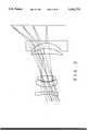
- FIG. 1a schematic view is shown illustrating a zoom lens system of the present invention, which is composed of five lens elements 1, 2, 3, 4, and 5 forming an optical lens system.
- the first three lens elements 1, 2, and 3form a positive front lens group F and the last two lens elements 4 and 5 form a negative rear lens group R.
- An airspace SPis reserved between the front lens group F and the rear lens group R, and the airspace is made variable to effect zooming operation.
- the front lens grouphas a positive refractive power while the rear lens group has a negative refractive power.
- This inventionis a miniature zoom lens system composed of five lens elements, which is suitable for use in a 35 mm lens shutter camera.
- the reference numerals R1 and R2represent the lens surface of the first lens element 1
- the reference numerals R3 and R4represent the lens surface of the second lens element 2
- the reference numerals R5 and R6represent the lens surface of the third lens element 3
- the reference numerals R7 and R8represent the lens surface of the fourth lens element 4
- the reference numerals R9 and R10represent the lens surface of the fourth lens element 5.
- the first lens element 1is a negative lens element whose concave surface is arranged to the object side of the lens system.
- the second lens elements 2 in the front lens group Fis a negative lens element.
- the third lens elements 3is a positive lens element.
- the fourth lens element 4is a positive lens whose concave surface is arranged to the object side of the lens system.
- the fifth lens element 5is a negative lens whose concave surface is arranged to the object side of the lens system.
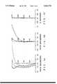
- FIG. 2is a schematic view illustrating refraction of rays through the lens elements from the object side to the image side of the lens systems of the present invention in wide-angle mode of operation.
- FIGS. 2A through 2Cshow the various aberrations of the lens system of FIG. 2 in wide-angle position.
- FIG. 2Ashows the longitudinal spherical aberrations of the lens system.
- FIG. 2Bshows the astigmatism and the field curvature of the lens system.
- FIG. 2Cshows the distortion of the lens system.
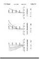
- FIG. 3is a schematic view illustrating refraction of rays through the lens elements from the object side to the image side of the lens systems of the present invention at the intermediate focal length position.
- FIGS. 3A through 3Cshow the various aberrations of the lens system of FIG. 3 at the intermediate focal length position.
- FIG. 3Ashows the longitudinal spherical aberrations of the lens system.
- FIG. 3Bshows the astigmatism and the field curvature of the lens system.
- FIG. 3Cshows the distortion of the lens system.
- FIG. 4is a schematic view illustrating refraction of rays through the lens elements from the object side to the image side of the lens systems of the present invention in the telephoto position.
- FIGS. 4A through 4Cshow the various aberrations of the lens system of FIG. 4 in the telephoto position.
- FIG. 4Ashows the longitudinal spherical aberrations of the lens system.
- FIG. 4Bshows the astigmatism and the field curvature of the lens system.
- FIG. 4Cshows the distortion of the lens system.
- the front lens group of the lens systemincludes at least one aspheric lens.
- the rear lens groupalso includes at least one aspheric lens.
- the feature of the aspheric lensmay be indicated by the following equation: ##EQU1## wherein: Z represents the sag of the lens;
- Crepresents the curvature of the lens
- Krepresents the Konic Constant
- Yrepresents the height of the lens from the optical axis of the lens system
- Arepresents the 4th order deformation coefficient
- Drepresents the 10th order deformation coefficient.
- symbol Frepresents the focal length of the zoom lens system
- Direpresents the thickness of respective lens along the optical axis
- Nirepresents the axis
- Virepresents the Abbe's number of respective lens.
- D6is a variable distance, and its relationship with various focal lengths is as follows:
- the lens surfaces R3, R5 and R8are aspheric surface, and the aspheric coefficients (with reference to the equation of aspheric surface) of respective surface are as follows:
- FIG. 5is a schematic view illustrating refraction of rays through the lens elements from the object side to the image side of the lens systems of the second embodiment of the present invention in wide-angle mode of operation.
- FIGS. 5A through 5Cshow the various aberrations of the lens system of FIG. 5 in wide-angle position.
- FIG. 5Ashows the longitudinal spherical aberrations of the lens system.
- FIG. 5Bshows the astigmatism and the field curvature of the lens system.
- FIG. 5Cshows the distortion of the lens system.
- FIG. 6is a schematic view illustrating refraction of rays through the lens elements from the object side to the image side of the lens systems of the present invention at the intermediate focal length position.
- FIGS. 6A through 6Cshow the various aberrations of the lens system of FIG. 6 at the intermediate focal length position.
- FIG. 6Ashows the longitudinal spherical aberrations of the lens system.
- FIG. 6Bshows the astigmatism and the field curvature of the lens system.
- FIG. 6Cshows the distortion of the lens system.
- FIG. 7is a schematic view illustrating refraction of rays through the lens elements from the object side to the image side of the lens systems of the present invention in the telephoto position.
- FIGS. 7A through 7Cshow the various aberrations of the lens system of FIG. 7 in the telephoto position.
- FIG. 7Ashows the longitudinal spherical aberrations of the lens system.
- FIG. 7Bshows the astigmatism and the field curvature of the lens system.
- FIG. 7Cshows the distortion of the lens system.
- the front lens group of the lens systemincludes at least one aspheric lens.
- the rear lens groupalso includes at least one aspheric lens.
- the equation of the aspheric lens of this embodimentis the same as that in the first embodiment.
- D6is the variable distance, and its relationship with focal length is as follows:
- the lens surfaces R5 and R8are aspheric surfaces, and the surface coefficients of respective surfaces are as follows:
- the zoom lens system described aboveemploys only five lens elements, which provides the features of a small outer diameter, short total length and few lens elements, and is particularly suitable for use in the 35 mm lens shutter camera. It will be obvious to those skilled in the art to use this invention according to the above detailed description. While the arrangement herein described constitutes a preferred embodiment of this invention, it is to be understood that various changes and modifications may be made therein without departing from the scope and spirit of the invention as defined in the appended claim.
Landscapes
- Physics & Mathematics (AREA)
- General Physics & Mathematics (AREA)
- Optics & Photonics (AREA)
- Lenses (AREA)
Abstract
Description
______________________________________ F = 36.5-67 f/# = 5.6-7.41 Ri Di Ni Vi ______________________________________ R1 = -18.3341 D1 = 1.4515 N1 = 1.7552 V1 = 27.5 R2 = -45.4862 D2 = 2.9899 R3 = 10.59608 D3 = 3.0 N3 = 1.585 V3 = 30.0 R4 = 9.2175 D4 = 0.674 R5 = 15.1156 D5 = 3.4 N5 = 1.491 V5 = 57.1 R6 = -16.7952 D6 = 13.12423 R7 = -62.8335 D7 = 3.446 N7 = 1.491 V7 = 57.1 R8 = -18.47548 D8 = 3.5232 R9 = -11.2346 D9 = 1.4 N9 = 1.62299 V9 = 58.2 R10 = Infinite ______________________________________
______________________________________ Focal Length 36.5 51.73 67 Variable distance D6 13.1242 7.4559 3.7993 f/# 5.67 7.18 7.41 ______________________________________
______________________________________ The aspheric coefficient A -4.00824E-5 B -5.17054E-7 of the lens surface No.3 C -3.50451E-8 D -6.26103E-11 K -0.254308 The aspheric coefficient A 2.14148E-5 B 5.83767E-7 of the lens surface No.5 C 1.04688E-7 D -1.72681E-11 K -0.028111 The aspheric coefficient A -5.71816E-6 B 4.30591E-7 of the lens surface No.8 C -8.20702E-9 D 5.38013E-11 K 1.968217 ______________________________________
______________________________________ F = 36-67 f/# = 6.08-11.167 Ri Di Ni Vi ______________________________________ R1 = -17.28965 D1 = 1.4 N1 = 1.7552 V1 = 27.5 R2 = -60.33899 D2 = 3.01137 R3 = 9.06238 D3 = 3.0 N3 = 1.5855 V3 = 30.0256 R4 = 7.90708 D4 = 0.468163 R5 = 10.94986 D5 = 3.330207 N5 = 1.491 V5 = 57.1744 R6 = -19.75281 D6 = 12.438381 R7 = -68.87535 D7 = 3.189951 N7 = 1.491 V7 = 57.1744 R8 = -17.8818 D8 = 3.285764 R9 = -10.29119 D9 = 1.4 N9 = 1.62299 V9 = 58.2 R10 = Infinite ______________________________________
______________________________________ Focal Length 36.5 47.1 67 Variable space D6 12.4384 8.0138 3.4885 f/# 6.08 7.85 11.1667 ______________________________________
______________________________________ The aspheric Coefficient A -1.47693E-5 B -7.99892E-6 of the lens surface R5 C 7.87144E-7 D -3.07359E-8 K -0.906256 The aspheric coefficient A -5.3135E-6 B 3.64547E-7 of the lens surface R8 C -1.00188E-8 D 9.54268E-11 K 2.407465 ______________________________________
Claims (10)
Priority Applications (1)
| Application Number | Priority Date | Filing Date | Title |
|---|---|---|---|
| US08/163,480US5541772A (en) | 1993-12-07 | 1993-12-07 | Camera zoom lens |
Applications Claiming Priority (1)
| Application Number | Priority Date | Filing Date | Title |
|---|---|---|---|
| US08/163,480US5541772A (en) | 1993-12-07 | 1993-12-07 | Camera zoom lens |
Publications (1)
| Publication Number | Publication Date |
|---|---|
| US5541772Atrue US5541772A (en) | 1996-07-30 |
Family
ID=22590189
Family Applications (1)
| Application Number | Title | Priority Date | Filing Date |
|---|---|---|---|
| US08/163,480Expired - LifetimeUS5541772A (en) | 1993-12-07 | 1993-12-07 | Camera zoom lens |
Country Status (1)
| Country | Link |
|---|---|
| US (1) | US5541772A (en) |
Cited By (10)
| Publication number | Priority date | Publication date | Assignee | Title |
|---|---|---|---|---|
| US5663837A (en)* | 1995-04-04 | 1997-09-02 | Nikon Corporation | Lens system |
| US5796527A (en)* | 1995-06-19 | 1998-08-18 | Nikon Corporation | Small zoom optical system |
| US5999331A (en)* | 1997-02-07 | 1999-12-07 | Minolta Co., Ltd. | Zoom lens system |
| US6333824B1 (en)* | 1998-09-10 | 2001-12-25 | Olympus Optical Co., Ltd. | Zoom lens system consisting of two lens units |
| US20040160518A1 (en)* | 2003-01-02 | 2004-08-19 | Lg Electronics Inc. | IRIS recognition camera for an iris recognition system and a method of operation for an iris recognition camera |
| US20050041140A1 (en)* | 2003-08-22 | 2005-02-24 | Fuji Photo Film Co., Ltd. | Digital camera |
| US20080094727A1 (en)* | 2006-10-23 | 2008-04-24 | Young Optics Inc. | Zoom lens |
| US20090015936A1 (en)* | 2007-07-13 | 2009-01-15 | Young Optics Inc. | Zoom lens |
| CN101221278B (en)* | 2007-01-08 | 2010-05-19 | 扬明光学股份有限公司 | Zoom lens |
| US20160062078A1 (en)* | 2014-08-27 | 2016-03-03 | Ability Enterprise Co., Ltd. | Optical lens |
Citations (9)
| Publication number | Priority date | Publication date | Assignee | Title |
|---|---|---|---|---|
| US4682860A (en)* | 1980-03-14 | 1987-07-28 | Canon Kabushiki Kaisha | Ultrasmall size zoom lens |
| US4772106A (en)* | 1986-04-25 | 1988-09-20 | Olympus Optical Co., Ltd. | Compact zoom lens system |
| US4818081A (en)* | 1987-08-28 | 1989-04-04 | Asahi Kogaku Kogyo Kabushiki Kaisha | Zoom lens system for use in compact camera |
| US4830476A (en)* | 1987-05-08 | 1989-05-16 | Olympus Optical Co., Ltd. | Compact zoom lens system |
| US4838669A (en)* | 1987-03-17 | 1989-06-13 | Olympus Optical Co., Ltd. | Compact zoom lens system |
| US4991945A (en)* | 1989-07-05 | 1991-02-12 | Eastman Kodak Company | Zoom lens |
| JPH05113537A (en)* | 1991-10-22 | 1993-05-07 | Olympus Optical Co Ltd | Zoom lens using plastic lens |
| US5270867A (en)* | 1991-12-13 | 1993-12-14 | Eastman Kodak Company | Compact zoom lens having a weak front lens group |
| US5412508A (en)* | 1993-07-13 | 1995-05-02 | Industrial Technology Research Institute | Compact zoom lens system |
- 1993
- 1993-12-07USUS08/163,480patent/US5541772A/ennot_activeExpired - Lifetime
Patent Citations (10)
| Publication number | Priority date | Publication date | Assignee | Title |
|---|---|---|---|---|
| US4682860A (en)* | 1980-03-14 | 1987-07-28 | Canon Kabushiki Kaisha | Ultrasmall size zoom lens |
| US4772106A (en)* | 1986-04-25 | 1988-09-20 | Olympus Optical Co., Ltd. | Compact zoom lens system |
| US4838669A (en)* | 1987-03-17 | 1989-06-13 | Olympus Optical Co., Ltd. | Compact zoom lens system |
| US4830476A (en)* | 1987-05-08 | 1989-05-16 | Olympus Optical Co., Ltd. | Compact zoom lens system |
| US4818081A (en)* | 1987-08-28 | 1989-04-04 | Asahi Kogaku Kogyo Kabushiki Kaisha | Zoom lens system for use in compact camera |
| US4991945A (en)* | 1989-07-05 | 1991-02-12 | Eastman Kodak Company | Zoom lens |
| JPH05113537A (en)* | 1991-10-22 | 1993-05-07 | Olympus Optical Co Ltd | Zoom lens using plastic lens |
| US5386321A (en)* | 1991-10-22 | 1995-01-31 | Olympus Optical Co., Ltd. | Zoom lens |
| US5270867A (en)* | 1991-12-13 | 1993-12-14 | Eastman Kodak Company | Compact zoom lens having a weak front lens group |
| US5412508A (en)* | 1993-07-13 | 1995-05-02 | Industrial Technology Research Institute | Compact zoom lens system |
Cited By (15)
| Publication number | Priority date | Publication date | Assignee | Title |
|---|---|---|---|---|
| US5663837A (en)* | 1995-04-04 | 1997-09-02 | Nikon Corporation | Lens system |
| US5796527A (en)* | 1995-06-19 | 1998-08-18 | Nikon Corporation | Small zoom optical system |
| US5999331A (en)* | 1997-02-07 | 1999-12-07 | Minolta Co., Ltd. | Zoom lens system |
| US6333824B1 (en)* | 1998-09-10 | 2001-12-25 | Olympus Optical Co., Ltd. | Zoom lens system consisting of two lens units |
| US20040160518A1 (en)* | 2003-01-02 | 2004-08-19 | Lg Electronics Inc. | IRIS recognition camera for an iris recognition system and a method of operation for an iris recognition camera |
| US7768572B2 (en)* | 2003-01-02 | 2010-08-03 | Lg Electronics Inc. | Iris recognition camera for an iris recognition system and a method of operation for an iris recognition camera |
| US7336304B2 (en)* | 2003-08-22 | 2008-02-26 | Fujifilm Corporation | Digital camera with zoom lens |
| US20050041140A1 (en)* | 2003-08-22 | 2005-02-24 | Fuji Photo Film Co., Ltd. | Digital camera |
| US20080094727A1 (en)* | 2006-10-23 | 2008-04-24 | Young Optics Inc. | Zoom lens |
| US7450320B2 (en) | 2006-10-23 | 2008-11-11 | Young Optics Inc. | Zoom lens |
| CN101221278B (en)* | 2007-01-08 | 2010-05-19 | 扬明光学股份有限公司 | Zoom lens |
| US20090015936A1 (en)* | 2007-07-13 | 2009-01-15 | Young Optics Inc. | Zoom lens |
| US7643220B2 (en) | 2007-07-13 | 2010-01-05 | Young Optics Inc. | Zoom lens |
| US20160062078A1 (en)* | 2014-08-27 | 2016-03-03 | Ability Enterprise Co., Ltd. | Optical lens |
| US10295800B2 (en)* | 2014-08-27 | 2019-05-21 | Ability Enterprise Co., Ltd. | Optical lens |
Similar Documents
| Publication | Publication Date | Title |
|---|---|---|
| US5541773A (en) | Two-unit zoom lens system | |
| US6064531A (en) | Zoom lens system | |
| JP3478637B2 (en) | Small zoom lens | |
| JPH04267212A (en) | Ultra wide angle lens | |
| US5148321A (en) | Compact zoom lens system | |
| US4572620A (en) | Zoom lens system | |
| US6236522B1 (en) | Photographic optical system | |
| US6097547A (en) | Front converter lens system using a diffractive surface | |
| JPH1123968A (en) | Zoom lens having diffraction surface | |
| US4679913A (en) | Vari-focal objective lens of short total length | |
| US4323302A (en) | Wide-angle zoom lens system | |
| US5646777A (en) | Keplerian zoom finder optical system | |
| US5541772A (en) | Camera zoom lens | |
| US4830474A (en) | Variable magnification optical system | |
| US5381269A (en) | Zoom lens | |
| US5353159A (en) | Three-unit compact zoom lens system | |
| JPH07253540A (en) | Zoom lens | |
| JP2808905B2 (en) | Zoom lens | |
| US5627677A (en) | Rear conversion lens with vibration-reduction function | |
| US5539581A (en) | Zoom lens system | |
| US5508848A (en) | Wide-angle lens for film-combined type cameras | |
| JP3331223B2 (en) | Small two-group zoom lens | |
| US6094313A (en) | Zoom lens system | |
| JPH09113800A (en) | Retro focus lens | |
| US3502394A (en) | Lens system of large telephoto ratio |
Legal Events
| Date | Code | Title | Description |
|---|---|---|---|
| AS | Assignment | Owner name:INDUSTRIAL TECHNOLOGY RESEARCH INSTITUTE, TAIWAN Free format text:ASSIGNMENT OF ASSIGNORS INTEREST;ASSIGNOR:LIN, CHIEH-YU;REEL/FRAME:006791/0882 Effective date:19931130 | |
| STCF | Information on status: patent grant | Free format text:PATENTED CASE | |
| FEPP | Fee payment procedure | Free format text:PAYOR NUMBER ASSIGNED (ORIGINAL EVENT CODE: ASPN); ENTITY STATUS OF PATENT OWNER: LARGE ENTITY | |
| FPAY | Fee payment | Year of fee payment:4 | |
| REMI | Maintenance fee reminder mailed | ||
| FEPP | Fee payment procedure | Free format text:PAT HOLDER NO LONGER CLAIMS SMALL ENTITY STATUS, ENTITY STATUS SET TO UNDISCOUNTED (ORIGINAL EVENT CODE: STOL); ENTITY STATUS OF PATENT OWNER: LARGE ENTITY | |
| FEPP | Fee payment procedure | Free format text:PAYOR NUMBER ASSIGNED (ORIGINAL EVENT CODE: ASPN); ENTITY STATUS OF PATENT OWNER: LARGE ENTITY Free format text:PAYER NUMBER DE-ASSIGNED (ORIGINAL EVENT CODE: RMPN); ENTITY STATUS OF PATENT OWNER: LARGE ENTITY | |
| FPAY | Fee payment | Year of fee payment:8 | |
| FPAY | Fee payment | Year of fee payment:12 | |
| REMI | Maintenance fee reminder mailed | ||
| AS | Assignment | Owner name:TRANSPACIFIC IP 1 LTD.,, TAIWAN Free format text:ASSIGNMENT OF ASSIGNORS INTEREST;ASSIGNOR:INDUSTRIAL TECHNOLOGY RESEARCH INSTITUTE;REEL/FRAME:021901/0870 Effective date:20081104 |