US5541622A - Miniature isometric joystick - Google Patents
Miniature isometric joystickDownload PDFInfo
- Publication number
- US5541622A US5541622AUS08/104,777US10477793AUS5541622AUS 5541622 AUS5541622 AUS 5541622AUS 10477793 AUS10477793 AUS 10477793AUS 5541622 AUS5541622 AUS 5541622A
- Authority
- US
- United States
- Prior art keywords
- force
- user
- actuator
- shaft
- actuator assembly
- Prior art date
- Legal status (The legal status is an assumption and is not a legal conclusion. Google has not performed a legal analysis and makes no representation as to the accuracy of the status listed.)
- Expired - Lifetime
Links
Images


Classifications
- G—PHYSICS
- G05—CONTROLLING; REGULATING
- G05G—CONTROL DEVICES OR SYSTEMS INSOFAR AS CHARACTERISED BY MECHANICAL FEATURES ONLY
- G05G9/00—Manually-actuated control mechanisms provided with one single controlling member co-operating with two or more controlled members, e.g. selectively, simultaneously
- G05G9/02—Manually-actuated control mechanisms provided with one single controlling member co-operating with two or more controlled members, e.g. selectively, simultaneously the controlling member being movable in different independent ways, movement in each individual way actuating one controlled member only
- G05G9/04—Manually-actuated control mechanisms provided with one single controlling member co-operating with two or more controlled members, e.g. selectively, simultaneously the controlling member being movable in different independent ways, movement in each individual way actuating one controlled member only in which movement in two or more ways can occur simultaneously
- G05G9/047—Manually-actuated control mechanisms provided with one single controlling member co-operating with two or more controlled members, e.g. selectively, simultaneously the controlling member being movable in different independent ways, movement in each individual way actuating one controlled member only in which movement in two or more ways can occur simultaneously the controlling member being movable by hand about orthogonal axes, e.g. joysticks
- G—PHYSICS
- G06—COMPUTING OR CALCULATING; COUNTING
- G06F—ELECTRIC DIGITAL DATA PROCESSING
- G06F3/00—Input arrangements for transferring data to be processed into a form capable of being handled by the computer; Output arrangements for transferring data from processing unit to output unit, e.g. interface arrangements
- G06F3/01—Input arrangements or combined input and output arrangements for interaction between user and computer
- G06F3/02—Input arrangements using manually operated switches, e.g. using keyboards or dials
- G06F3/0202—Constructional details or processes of manufacture of the input device
- G06F3/021—Arrangements integrating additional peripherals in a keyboard, e.g. card or barcode reader, optical scanner
- G06F3/0213—Arrangements providing an integrated pointing device in a keyboard, e.g. trackball, mini-joystick
- G—PHYSICS
- G06—COMPUTING OR CALCULATING; COUNTING
- G06F—ELECTRIC DIGITAL DATA PROCESSING
- G06F3/00—Input arrangements for transferring data to be processed into a form capable of being handled by the computer; Output arrangements for transferring data from processing unit to output unit, e.g. interface arrangements
- G06F3/01—Input arrangements or combined input and output arrangements for interaction between user and computer
- G06F3/02—Input arrangements using manually operated switches, e.g. using keyboards or dials
- G06F3/023—Arrangements for converting discrete items of information into a coded form, e.g. arrangements for interpreting keyboard generated codes as alphanumeric codes, operand codes or instruction codes
- G—PHYSICS
- G06—COMPUTING OR CALCULATING; COUNTING
- G06F—ELECTRIC DIGITAL DATA PROCESSING
- G06F3/00—Input arrangements for transferring data to be processed into a form capable of being handled by the computer; Output arrangements for transferring data from processing unit to output unit, e.g. interface arrangements
- G06F3/01—Input arrangements or combined input and output arrangements for interaction between user and computer
- G06F3/03—Arrangements for converting the position or the displacement of a member into a coded form
- G06F3/033—Pointing devices displaced or positioned by the user, e.g. mice, trackballs, pens or joysticks; Accessories therefor
- G06F3/0338—Pointing devices displaced or positioned by the user, e.g. mice, trackballs, pens or joysticks; Accessories therefor with detection of limited linear or angular displacement of an operating part of the device from a neutral position, e.g. isotonic or isometric joysticks
- H—ELECTRICITY
- H01—ELECTRIC ELEMENTS
- H01H—ELECTRIC SWITCHES; RELAYS; SELECTORS; EMERGENCY PROTECTIVE DEVICES
- H01H13/00—Switches having rectilinearly-movable operating part or parts adapted for pushing or pulling in one direction only, e.g. push-button switch
- H01H13/70—Switches having rectilinearly-movable operating part or parts adapted for pushing or pulling in one direction only, e.g. push-button switch having a plurality of operating members associated with different sets of contacts, e.g. keyboard
- H01H13/78—Switches having rectilinearly-movable operating part or parts adapted for pushing or pulling in one direction only, e.g. push-button switch having a plurality of operating members associated with different sets of contacts, e.g. keyboard characterised by the contacts or the contact sites
- H01H13/785—Switches having rectilinearly-movable operating part or parts adapted for pushing or pulling in one direction only, e.g. push-button switch having a plurality of operating members associated with different sets of contacts, e.g. keyboard characterised by the contacts or the contact sites characterised by the material of the contacts, e.g. conductive polymers
- H—ELECTRICITY
- H01—ELECTRIC ELEMENTS
- H01H—ELECTRIC SWITCHES; RELAYS; SELECTORS; EMERGENCY PROTECTIVE DEVICES
- H01H13/00—Switches having rectilinearly-movable operating part or parts adapted for pushing or pulling in one direction only, e.g. push-button switch
- H01H13/70—Switches having rectilinearly-movable operating part or parts adapted for pushing or pulling in one direction only, e.g. push-button switch having a plurality of operating members associated with different sets of contacts, e.g. keyboard
- H01H13/78—Switches having rectilinearly-movable operating part or parts adapted for pushing or pulling in one direction only, e.g. push-button switch having a plurality of operating members associated with different sets of contacts, e.g. keyboard characterised by the contacts or the contact sites
- H01H13/807—Switches having rectilinearly-movable operating part or parts adapted for pushing or pulling in one direction only, e.g. push-button switch having a plurality of operating members associated with different sets of contacts, e.g. keyboard characterised by the contacts or the contact sites characterised by the spatial arrangement of the contact sites, e.g. superimposed sites
- G—PHYSICS
- G05—CONTROLLING; REGULATING
- G05G—CONTROL DEVICES OR SYSTEMS INSOFAR AS CHARACTERISED BY MECHANICAL FEATURES ONLY
- G05G9/00—Manually-actuated control mechanisms provided with one single controlling member co-operating with two or more controlled members, e.g. selectively, simultaneously
- G05G9/02—Manually-actuated control mechanisms provided with one single controlling member co-operating with two or more controlled members, e.g. selectively, simultaneously the controlling member being movable in different independent ways, movement in each individual way actuating one controlled member only
- G05G9/04—Manually-actuated control mechanisms provided with one single controlling member co-operating with two or more controlled members, e.g. selectively, simultaneously the controlling member being movable in different independent ways, movement in each individual way actuating one controlled member only in which movement in two or more ways can occur simultaneously
- G05G9/047—Manually-actuated control mechanisms provided with one single controlling member co-operating with two or more controlled members, e.g. selectively, simultaneously the controlling member being movable in different independent ways, movement in each individual way actuating one controlled member only in which movement in two or more ways can occur simultaneously the controlling member being movable by hand about orthogonal axes, e.g. joysticks
- G05G2009/0474—Manually-actuated control mechanisms provided with one single controlling member co-operating with two or more controlled members, e.g. selectively, simultaneously the controlling member being movable in different independent ways, movement in each individual way actuating one controlled member only in which movement in two or more ways can occur simultaneously the controlling member being movable by hand about orthogonal axes, e.g. joysticks characterised by means converting mechanical movement into electric signals
- G05G2009/04762—Force transducer, e.g. strain gauge
- H—ELECTRICITY
- H01—ELECTRIC ELEMENTS
- H01H—ELECTRIC SWITCHES; RELAYS; SELECTORS; EMERGENCY PROTECTIVE DEVICES
- H01H3/00—Mechanisms for operating contacts
- H01H3/02—Operating parts, i.e. for operating driving mechanism by a mechanical force external to the switch
- H01H2003/0293—Operating parts, i.e. for operating driving mechanism by a mechanical force external to the switch with an integrated touch switch
- H—ELECTRICITY
- H01—ELECTRIC ELEMENTS
- H01H—ELECTRIC SWITCHES; RELAYS; SELECTORS; EMERGENCY PROTECTIVE DEVICES
- H01H2201/00—Contacts
- H01H2201/02—Piezo element
- H—ELECTRICITY
- H01—ELECTRIC ELEMENTS
- H01H—ELECTRIC SWITCHES; RELAYS; SELECTORS; EMERGENCY PROTECTIVE DEVICES
- H01H2201/00—Contacts
- H01H2201/022—Material
- H01H2201/032—Conductive polymer; Rubber
- H01H2201/036—Variable resistance
- H—ELECTRICITY
- H01—ELECTRIC ELEMENTS
- H01H—ELECTRIC SWITCHES; RELAYS; SELECTORS; EMERGENCY PROTECTIVE DEVICES
- H01H2221/00—Actuators
- H01H2221/008—Actuators other then push button
- H01H2221/012—Joy stick type
- H—ELECTRICITY
- H01—ELECTRIC ELEMENTS
- H01H—ELECTRIC SWITCHES; RELAYS; SELECTORS; EMERGENCY PROTECTIVE DEVICES
- H01H2225/00—Switch site location
- H01H2225/018—Consecutive operations
- H—ELECTRICITY
- H01—ELECTRIC ELEMENTS
- H01H—ELECTRIC SWITCHES; RELAYS; SELECTORS; EMERGENCY PROTECTIVE DEVICES
- H01H2225/00—Switch site location
- H01H2225/03—Different type of switches
- H—ELECTRICITY
- H01—ELECTRIC ELEMENTS
- H01H—ELECTRIC SWITCHES; RELAYS; SELECTORS; EMERGENCY PROTECTIVE DEVICES
- H01H2239/00—Miscellaneous
- H01H2239/006—Containing a capacitive switch or usable as such
- H—ELECTRICITY
- H01—ELECTRIC ELEMENTS
- H01H—ELECTRIC SWITCHES; RELAYS; SELECTORS; EMERGENCY PROTECTIVE DEVICES
- H01H2239/00—Miscellaneous
- H01H2239/052—Strain gauge
- Y—GENERAL TAGGING OF NEW TECHNOLOGICAL DEVELOPMENTS; GENERAL TAGGING OF CROSS-SECTIONAL TECHNOLOGIES SPANNING OVER SEVERAL SECTIONS OF THE IPC; TECHNICAL SUBJECTS COVERED BY FORMER USPC CROSS-REFERENCE ART COLLECTIONS [XRACs] AND DIGESTS
- Y10—TECHNICAL SUBJECTS COVERED BY FORMER USPC
- Y10T—TECHNICAL SUBJECTS COVERED BY FORMER US CLASSIFICATION
- Y10T74/00—Machine element or mechanism
- Y10T74/20—Control lever and linkage systems
- Y10T74/20012—Multiple controlled elements
- Y10T74/20201—Control moves in two planes
Definitions
- the present inventionrelates generally to methods and apparatus for receiving manual user input for effecting directional control such as controlling cursor movement on a computer display screen or controlling movement of an apparatus such as a machine or robot.
- Isometric apparatus for manual analog inputare sometimes known as "pointing devices” or “joysticks”. More specifically, one aspect of the present invention includes an improved isometric joystick.
- Prior art pointing devicessuch as a joystick are known. What others have failed to appreciate is the ergonomic implications of mechanical and electrical null regions which must be traversed at the outset of a pointing operation.
- a usergets no response to lateral displacement initially, until an electrode makes initial contact, for example, with an elastomeric resistive layer.
- the initial contactcauses a step response, as resistance drops from infinity to a measurable value--a jump the user may not have anticipated or desired.
- forceis increased, resistance falls rapidly, over some range, and finally falls more slowly with the application of additional force. All of this is disconcerting to a user for most applications. What is needed is to provide for pointing which is smoothly and consistently responsive to user input from the outset of the pointing operation by controlling such null regions.
- pointing devicesare not sensitive to vertical or z-axis force. Forces applied laterally, i.e., in the x-y axis plane, move a cursor in the corresponding direction on a computer or other information display screen. It would be desirable for a vertical force, e.g., down the shaft of a joystick-type controller, to produce a proportional signal. Such a signal could be used for example to control line width while drawing as a function of z-axis force on the pointing device. Z-axis force could also be used to control speed or acceleration of a cursor or apparatus being manipulated.
- U.S. Pat. No. 4,313,113 to David Thornburgemploys four orthogonal variable-resistance pressure transducers, each transducer comprising a coordinate electrode spaced from a cooperating electrode, at least one of the electrodes being an elastomeric sheet material formed of a carbon loaded polyolefin.
- the path resistance through the transducergoes down as applied pressure goes up.
- the electrodesare spaced from the elastomeric layer, at rest, so that there is a mechanical and electrical null region before the system responds to a force input, followed by a step response when the electrode layers make initial contact.
- U.S. Pat. No. 4,439,648(Reiner et al.) is directed to a basic stand-alone joystick.
- the handlerests on a rigid pivot so that vertical force is ignored.
- the handleis coupled to an actuator portion spaced from all four switches, so there is a neutral or null region of displacement before any switch is closed.
- the switchesare conventional, yielding only a binary signal, without regard to force.
- U.S. Pat. No. 4,408,103discloses a miniaturized joystick adapted for mounting in a wristwatch.
- the joystick handlerests in a hollowed-out bearing surface so that none of the switches is actuated by a downward force on the handle.
- the switch actuating meansis maintained spaced from all the switches by a resilient rubber sheet layer, so once again there is a neutral or null region of displacement before any of the switches is closed.
- the switchesare miniaturized by forming them as interleaved electrodes on a PCB. When the handle is pivoted, an actuator pushes a conductive region of the resilient layer into contact with a corresponding switch. The switches each yield a binary output, so lateral force beyond an initial detect is ignored.
- U.S. Pat. No. 4,246,452(Chandler) shows another joystick type device, here having 16 possible output signals.
- the mechanismagain employs a handle having a depending member that rests in a hollowed out bearing surface.
- the switcheseach provide a binary signal, independent of lateral force beyond a threshold force; vertical force is ignored; and, the actuator is spaced from the switches to provide a null region.
- U.S. Pat. No. 4,680,577discloses a multipurpose keyswitch that serves both as a regular typing key, preferably located in the "home row" (asdf-jkl;) of a keyboard, as well as a force-sensitive pointing device.
- the use of strain gauges as shown therein for force sensingis not commercially practical.
- Straayer et al.also suggests activating the cursor positioning capabilities of the multipurpose keyswitch by first closing an additional keyswitch on the keyboard. A separate keyswitch for that purpose, however, is cumbersome to use.
- the conventional mouseis essentially always "ON" for receiving pointing input.
- keyboard spaceis at a premium in today's small portable computers, so an additional dedicated key is to be avoided if possible.
- a keyswitch-integrated pointing devicefor example, a computer keyboard typing key having force sensors coupled to it so that the typing key can also function somewhat like a joystick for controlling a cursor.
- Such a "multipurpose keyswitch”presents mechanical design challenges in order to maintain a normal "feel” or tactile response of the keyswitch for typing operations.
- the joystick featuremust be carefully implemented so as to not interfere with the typing performance of the selected keyswitch.
- Another problem with an input system that employs a multipurpose keyswitchis detecting when the user is "pointing".
- the pointing devicetypically a "mouse" separate from the keyboard
- pointing informationcursor displacement data
- That architecturesegregates pointing data from typing data. Since the two input channels operate in parallel, both typing and pointing functions are always enabled.
- a multipurpose keyswitchcan only provide one function at a time. Which function the user intends (typing or pointing) must somehow be determined. A separate switch to enable the pointing function is undesirable for reasons stated above. The need remains, therefore, for improvements in joystick methods and apparatus to provide accurate pointing operations and other benefits discussed below, all at low cost.
- An object of the present inventionis improved pointing operations through use of a novel joystick apparatus.
- Another objectis to detect when a user is operating a joystick without distracting the user.
- Another objectis to detect when a user is operating a joystick without using additional space on a keyboard or other input panel for a dedicated switch.
- Another objectis to detect when a user is using a joystick without distorting the response of the joystick.
- Yet another objectis to provide a joystick having an integrated switch.
- Yet another objectis to provide a joystick apparatus that has no null zone.
- Yet another objectis to improve preloading mechanisms useful in a joystick for improved accuracy and reliability at minimum production cost.
- a further objectis to provided a joystick that senses vertical (downward) pressure as well as lateral pressure.
- a further objectis to detect all forces applied to a joystick by a user.
- Yet another objectis to provide a miniature joystick located between the existing keys in the primary typing area of a standard keyboard without modifying any of the existing keys.
- a methodfor acquiring directional data for controlling cursor movement on a visual display screen such as a computer display screen. More specifically, in the context of a computer keyboard having a baseplate and an array of existing keyswitches mounted on the baseplate, the new method includes selecting a location on the baseplate intermediate the existing keyswitches; symmetrically arranging a plurality of force sensing elements around the selected location, so that the force sensing elements do not interfere with operation of the existing keyswitches; providing an actuator assembly positioned on top of the force sensing elements and supported solely by the force sensing elements, the actuator assembly having a shaft extending upward from the selected location for operation by a user's fingertip.
- a pre-loading forceis applied to the actuator assembly along a Z axis normal to the base plate so as to force the actuator assembly against all of the force sensing elements in the absence of an external force on the shaft.
- the pre-loading forceis selected so as to bias the force sensing elements to an intermediate operating point, so that an external deflecting force applied to the shaft angularly offset from the Z axis increases the force on at least one of the force sensing elements and decreases the force on an opposing element, thereby providing force information in at least two of the force sensing elements in response to said deflection force.
- Another feature of the inventionis an integrated switch coupled to a top end of the shaft for detecting presence of the user's fingertip contacting the shaft. While the user's fingertip is not detected, the force sensing elements are measured, i.e. electrical signals are acquired, such as analog resistance or voltage values, to acquire an indication of applied force, thereby acquiring bias force information. Then, while presence of the user's fingertip is detected, the force sensing elements are measured again to acquire an indication of applied force, thereby acquiring pointing force information. Finally, the bias force information and the pointing force information may be combined to form directional data for controlling cursor movement on the visual display screen.
- the tip switchhas the advantage of being unobtrusive in use. It detects when a user is pointing, as pointing requires pressing on the tip of the joystick. But the tip switch relieves the user from having to explicitly actuate a separate switch to enable pointing. Therefore, the cognitive load and physical step of first actuating a separate switch before pointing are removed, with corresponding savings of the user's time. Moreover, the tip switch is small and has little or no travel, so a user may not even be aware of its presence. The tip switch allows the computer or other target system to readily distinguish "time to bias" (when the user is not pointing) from "time to point.”
- the inventionfurther includes a miniature joystick apparatus.
- the joystickincludes a generally flat, rigid base plate, although the known baseplate that exists in standard computer keyboards may be used for this purpose.
- a generally planar force-sensing assemblyis employed in substantially parallel contact with the base plate.
- An actuator assemblyis registered over the force-sensing assembly for applying forces to it, the actuator including an upright, rigid shaft coupled to an actuator plate.
- a preload springurges the actuator plate and the base plate together, thereby maintaining the actuator plate in constant contact with the force-sensing means so that the apparatus exhibits no dead zone in use.
- the preloading assemblyholds the assembly together in a manner in which does not cause binding.
- a switchis integrated into the top end of the joystick shaft for detecting presence of the user's fingertip.
- FIG. 1Ais a cross-sectional view of an improved joystick mechanism having an integrated switch according to the present invention.
- FIG. 1Bis a perspective view of a leaf spring assembly useful for preloading in a joystick of the type illustrated in FIG. 1A.
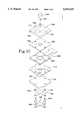
- FIG. 1Cis an exploded view of the joystick mechanism of FIG. 1A.
- FIG. 2is a cross-sectional view of an alternative joystick mechanism also having an integrated switch.
- FIG. 3Ais a perspective view of a joystick tip assembly having an integrated zero-travel switch.
- FIG. 3Bis a cross-sectional view of the tip assembly of FIG. 3A as well as an actuator coupled to the tip assembly.
- FIG. 4is an enlarged cross-sectional view of an alternative joystick tip assembly having an integrated switch.
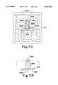
- FIG. 5Ais a partial top view of a keyboard having a joystick assembly mounted in between adjacent keyswitch guides of a keyboard.
- FIG. 5Bis a side view of the actuator assembly of the joystick of FIG. 5A.
- FIG. 6is a side view of a tapered joystick shaft disposed between adjacent standard keycaps of a keyboard.
- FIG. 7Ais a cross-sectional view of another alternative joystick mechanism.
- FIG. 7Bis a top view of a spring useful for central preloading in a joystick of the type illustrated in FIG. 7A.
- FIG. 8is a cross-sectional view of an alternative embodiment of an isometric joystick according to the present invention.
- FIG. 1Ashows a joystick mechanism according to the present invention.
- the joystickincludes an actuator assembly 150 having a rigid shaft portion 156, a flexible rubber tip 158 coupled to a top end of the shaft, and a generally horizontal actuator plate 152 fixed to the bottom end of the shaft 156.
- the actuator plate and shaftpreferably are formed of a sturdy, lightweight material such as a polymeric. They may be molded for volume production at low cost.
- the underside of the actuator plateincludes several protruding actuator surfaces or "bumps" 154 further described below. These bumps may be integrally formed with the actuator plate or may be adhered thereto.
- Shaft 156has a hollow core 160.
- the actuator assembly 150sits on top of a rubber dome sheet 165; the rubber dome sheet sits on top of a sensor assembly 168; the sensor assembly 168 sits on top of a keyboard membrane 172; and, the entire assembly sits on top of a flat, rigid base plate 174.
- the joystickneed not necessarily be implemented in a keyboard.
- membrane 172is not a keyboard membrane, but any similar structure arranged to provide a switch disposed generally below the actuator shaft, further described later. Preferably the switch is centered below the shaft.
- FIG. 1Cis an exploded view of the joystick mechanism of FIG. 1A.
- Sensor assembly 168 as illustratedcomprises four independent sensor elements, for example sensor element 169, all formed on a common substrate.
- the rubber dome sheet 165has a dome 166 formed therein which may include a recessed crater for contacting the membrane switch contacts 173.
- a generally flat, rigid back-up plate 176is disposed below and generally parallel to the base plate 174.
- Two or more mounting pins 164extend upward from the back-up plate, through registered clearance holes 182, to the actuator plate 152 for fixedly interconnecting the back-up plate and the actuator assembly.
- Clearance holes 182are sized to clear pins 164 both at rest and in use, and are formed in the base plate 174, spring 178, keyboard membrane 172, sensor assembly 168, and rubber dome sheet 165.
- Pins 164extend into fitting engagement holes in the actuator plate 152. The pins may be fastened, for example, with heat staking or threaded engagement.
- a four-element leaf spring 181 with leaves 178is located on the underside of base plate 174 between the base plate and the back-up plate 176. Spring 181 is compressed by back-up plate 176.
- the pre-load spring 181, disposed between the back-up plate 176 and the base plate 174,is formed of a resilient material, preferably a light gauge stainless steel.
- the fastening pins 164are installed so as to partially compress the pre-load spring. This arrangement holds the entire joystick assembly together without play or binding and, more particularly, applies a pre-load force to each of the force-sensing elements 169, thereby maintaining the actuator plate in constant contact with the force-sensing means so that the apparatus exhibits no dead zone in use.
- the force sensing elementspreferably comprise force-sensitive resistors ("FSR"s).
- force-sensitive resistor or "FSR" elementsfor example those commercially available from Interlink, Inc. of California, provide essentially infinite resistance when no force is applied to the element.
- FSR elementsWhen small initial force is applied, on the order of a hundred grams, the FSR elements instantly drop to an initial resistance on the order of a few hundred thousand ohms. This drastic change, or step response, is disconcerting to an operator and undesirable for most applications.
- the application of a pre-load force to the FSR deviceeliminates this initial step response problem.
- FSR elementsexhibit resistance to force characteristics that initially change very quickly and unpredictably, for example, exponentially and noisily, as force is further increased, moves into a more predictable region of operation.
- a pre-load forceto bias the FSR elements into this more predictable region of operation, the devices will exhibit a more predictable response to external forces applied by the operator.
- Preloading the sensors to a predetermined intermediate operating pointalso allows for differential sensing.
- an external lateral force applied to the joystick tip 158results in a differential signal in that the force applied to one of the force-sensing elements 169 is increased while the force applied to the force-sensing element opposite the first force-sensing element is decreased.
- a force applied in any direction off the X or Y axisresults in resistance to change in all four sensing elements. Note the absence of any pivot type supporting means as appear in a conventional joystick.
- downward or Z-axis forcesare coupled through the actuator surface bumps 154 to the sensor array 168.
- the present apparatusthereby measures the overall or net force applied by a user.
- a magnitude of the net forcecan be computed by summing the forces on all the sensors.
- the net applied force informationis useful in many applications, for example, to control cursor speed, or to provide Z axis control. Increasing the apparent cursor speed in response to a greater operator applied force provides a natural and ergonomically efficient response.
- the pre-load springalso affords the advantage of neutralizing manufacturing variations in the various components described, as well as obviating a pivot's high tolerance requirements.
- the compressed springtakes up variations in thickness of the elements in between the backup plate 176 and the actuator 150 to avoid any play or wobble in the system.
- a processing unit coupled to the force-sensing arraycan be arranged to calibrate itself. Specifically, the processor can define zero force as whatever resistances are provided by the force-sensing elements in the absence of externally applied forces.
- the joystick of FIG. 1Afurther includes an integrated switching mechanism described next.
- the switching mechanismcomprises a rubber tip 158 coupled to the top end of shaft 156 for actuation by a user's fingertip.
- the rubber tipis fixed to a central depending plunger 162 that extends down through core 160 inside of shaft 156.
- the depending plunger 162contacts the top of a low-travel rubber dome 166.
- Rubber dome 166is pre-formed in rubber dome sheet 165.
- the tipIn response to a generally downward external force applied to the top of tip 158, the tip deforms downward, moving the depending plunger downward through the bore so that a lower end of the plunger 162 deforms the rubber dome 166, driving it downward through a clearance hole in the sensor assembly 168 into contact with a membrane switch 173 provided for that purpose in the keyboard membrane 172. See FIG. 1C.
- a typical membrane switchtwo generally parallel membranes are separated by a third central spacing member.
- the membraneshave conductive pads in facing opposition.
- the spacing membermay be a thin plastic sheet material with holes in it, or it may comprise a thickened coating applied around the edge of the conductive pad on at least one of the membranes.
- the joystick tip 158is resilient and will retract depending member 162 upwards when finger pressure is removed, thereby opening the membrane switch. Downward displacement of depending member 162 is limited by the height of a gap 159 to a position adequate to actuate the membrane switch. Because of the small gap and resiliency of tip 158, only a slight force, hardly noticeable to the user, is necessary to close the switch. All additional force applied to tip 158 by the user's fingertip is transmitted through the actuator assembly to the sensor assembly to generate pointing data. Accordingly, the user is relieved from having to explicitly actuate a separate switch to enable pointing. Therefore, the cognitive load and physical step of first actuating a separate switch before pointing are removed, with corresponding savings of the user's time.
- FIG. 1Bis a perspective view of leaf spring assembly 181.
- the spring assemblyincludes four leaves 178, each leaf extending radially from a central pivot area 179 and having a clearance hole 182 at its distal end sized to clear a corresponding one of the mounting pins 164.
- the mounting pinsthus hold the spring assembly positioned below the base plate, while individual leaves are free to bend in response to rocking movement of the actuator assembly 150.
- Another important aspectis the preload leaf spring 181 having a smooth, central pivot area 179. This arrangement helps to automatically balance the pre-loading forces among the sensor elements (i.e. when no external force is present). When a fingertip is placed on rubber tip 158, the leaf spring central pivot area allows the actuator assembly to pivot slightly around the preload or standby position.
- the sensor assembly 168may have fewer, for example three, sensor elements. It is preferred but not essential that the spring assembly have a number of leaves equal to the number of sensor elements. In the embodiment illustrated, the spring leaves are positioned in between the sensor elements, from a top view, rather than aligned with each of them.
- FIG. 2shows an alternative joystick mechanism according to the present invention.
- a sensor assembly 204is disposed in parallel contact on top of a rigid base plate 206.
- An actuator assembly 186includes an upright shaft 188 having a hollow bore 198 and a horizontal actuator plate 190 fixed to the shaft.
- a rigid top plate 200is fixed in position in parallel to and spaced apart from base plate 206.
- Top plate 200includes a central aperture 199 spaced to clear the shaft 188 and allow pivoting or rocking motion of the actuator assembly without contacting the top plate.
- the force sensor assembly 204is pre-loaded by a compressed, helical pre-load spring 202 disposed between the top plate and the actuator plate 190.
- the actuator plate 190includes contoured actuator surfaces, in this example rubber bumps 192, fixed to the underside of the actuator plate for contacting the sensor assembly 204.
- each rubber bumppreferably has a spherical segment shape and is positioned for tangentially contacting a corresponding one of the sensor elements of sensor assembly 204.
- the top of shaft 188has a cap 194 coupled thereto.
- the capis formed of a pliable, resilient material such as a conductive rubber material and sized for fingertip operation, for example having a diameter in a range of approximately 1/8 to 1/2 inch.
- Cap 194has a depending electrode 196 which extends down through bore 198 to a point 208 where it contacts the sensor assembly 204. Preloading of the force sensor assembly is achieved by compressing spring 202 between upper plate 200 and the actuator plate 190. The actuator plate transmits force to the rubber bumps 192 to maintain them in contact with the sensor assembly, for example at contact point 210.
- the bottom plate 206 or a surrounding frameworkis connected at points not shown in this drawing to upper plate 200 so as to form a "sandwich" arrangement that holds the joystick assembly together and provides compression of spring 202 when the assembly is at rest (i.e. in the absence of any external force).
- a user's finger contacting cap 194causes a detectable change in capacitance that can be detected by external circuitry via depending electrode 196, contact point 208, and sensor assembly 204.
- the external circuitry(not shown) is connected via the sensor assembly using means known in the art to detect a change in capacitance due to a fingertip.
- the userapplies a fingertip to cap 194 and pushes on the joystick assembly, causing forces applied by the user to pass down through the actuator assembly into the sensors. No applied force or "travel" of the cap is necessary to detect presence of the user's finger. Accordingly, all applied forces are detected as force changes in the sensor assembly 204.
- the rubber dome sheet 165extends between the bump surfaces and the corresponding sensor elements 169 (FIG. 1C). This arrangement has been found to be advantageous in that the rubber dome sheet smoothly disperses or distributes forces applied through the actuator assembly to the sensor assembly.
- use of rubber bumps (or other compliant material), such as those illustrated in the embodiment of FIG. 2,obviate an intervening rubber sheet, and still provide good performance as the bumps themselves distribute applied forces over the sensor elements.
- the base plate 174(206 in FIG.2) provides a relatively rigid support to the underside of the sensor assembly 168 (204) in either embodiment so that forces applied through the actuator assembly are efficiently coupled to the sensor assembly.
- Helical spring 202 in FIG. 2provides a preloading function similar to that provided by a compressive pad disclosed in the parent case identified above. We have found that the compressive pad, however, is subject to greater degradation over time.
- FIG. 3is an enlarged, perspective view of a joystick tip. Such a tip may be applied, for example, to shaft 188 of FIG. 2 in place of the rubber cap 194.
- the joystick tip of FIG. 3has a central electrode 218 separated from an outer electrode 214 by an insulating gap 216. A cross-sectional view of the tip appears as FIG. 3B.
- the outer shell 212would enclose shaft 188.
- the central electrode 218is coupled to a depending portion (not shown) that extends through the central core 198 (FIG.2) for making electrical contact with a resistance detecting circuit (also not shown).
- An outer electrode 214extends down the outside of shaft 188 to a contact point on a circuit board of sensor assembly (not shown).
- FIG. 4is a cross-sectional view of a low-travel switching tip for a joystick.
- This type of joystick tipmay be used, for example, in connection with a joystick having an actuator assembly similar to actuator 186 in FIG. 2.
- This switching tipcomprises a hollow cap 224 formed of a pliable conductive material, such as a conductive rubber, fixed along its periphery to a joystick shaft 220, so that the cap covers the top end of the shaft.
- An interior electrode 232covers a central portion of the top end of the shaft, and includes a depending portion 238 that extends downward through a central bore in the shaft.
- a top surface 230 of the interior electrodeis spaced apart from an inside surface 228 of the cap 224, thereby forming a gap 226 therebetween.
- the interior electrode and the captogether form a normally-open switch.
- the inside surface 228 of the capis coupled along 240 to a conductive path 236 which extends down along shaft 220 for connection to an electrical circuit (not shown).
- the depending portion of the interior electrodealso is coupled to the circuit.
- a userpushes on the cap 224, it will deform so as to close the gap 226, thus bringing the inside cap surface 228 into physical and electrical contact with the top surface 230 of electrode 232 to close the switch.
- pressing on the cap 224 from an angle offset from verticalnonetheless will actuate the switch.
- the conductive rubber cap 224seats down on ledges 234 formed along the periphery of the shaft. These ledges maintain the cap spaced apart from the interior electrode at rest.
- FIG. 5Ais a top view of a small, three-element joystick assembly embedded between three conventional keys in an otherwise conventional keyboard. This context gives an indication of the size of the joystick.
- the joystick assembly shown in this figureis similar to the joystick assembly of FIG. 1A with the switching assembly portions of that assembly removed.
- the keys illustratedmay be located anywhere on the keyboard. Their particulars are known and are not important here.
- Each keyincludes a keycap, for example keycap 242, and a corresponding switch mechanism, e.g. 244, shown in phantom as the switch mechanisms are underneath the corresponding keycaps.
- the joystick assemblycomprises an actuator having a shaft 250 having, for example, an inverted T-shape in cross-section.
- a joystick tip 254is disposed on a top end of the shaft for operation by a user's fingertip.
- the joystick tipmay be similar to those described above such as the joystick tip of FIG. 3 or FIG. 4.
- the shaftcouples the joystick tip to an actuator plate 246 fixed to a lower end of the shaft.
- the actuator platehas horizontal arms, for example arm 246, extending radially from the shaft in between the switching mechanisms of the neighboring keys and below the neighboring keycaps.
- the number of armsgenerally equals the number of discrete force sensors, each arm overlying a corresponding one of the sensors.
- the exact shape of the actuator plate (or arms)is not critical, as long as it does not contact neighboring structures. Such contact would interfere with accurate sensing of forces applied to the tip by a user.
- the number of sensorsis flexible to a limited degree. At least two sensors are required to resolve a direction indicated by the user, e.g. for cursor control. Three sensors provide a measure of redundancy in case one of them fails. Size is the primary limiting factor in miniature applications. Moreover, more than four sensors provide little added benefit.
- FIG. 5Bis a front view of the joystick actuator of FIG. 5A showing its positioning relative to adjacent keycaps (shown in phantom).
- actuator bumps or surfaces 248protrude from the underside of the actuator plate 246 for contacting and transmitting forces to the force sensors (see FIG. 1A).
- the arrangement describedprovides for actuation of the joystick when needed without interfering with normal operation of the adjacent keys of the keyboard when the joystick is not needed.
- the shaftis sized so that the joystick tip extends only slightly above the top of the neighboring keycaps.
- FIG. 6is a side view of two adjacent keycaps 274, 275 with a joystick shaft 272 extending between them.
- the bottom end of the joystick shaft(not shown) is coupled to an actuator plate as described above.
- the shaft 272may have a T-shape in cross-section, as illustrated in FIG. 5.
- Keycaps 274, 275may be part of a computer keyboard, for example. The illustration is taken as viewed from the end of the keyboard, with the front of the keyboard (the long side closest to the user) toward the left of the drawing.
- the keycapstypically have sloped faces, for example keycap 274 has a sloped front face 269 and a sloped rear face 270. The front face often has a greater slope than the rear face.
- Keycap 275is essentially identical to keycap 274.
- Joystick shaft 272tapers outwardly adjacent the top end so that the top end of the shaft forms an enlarged user surface 258 for operation by the user's fingertip.
- the user surface 258may be part of the shaft 272, or may be formed by a rubber cap connected to the top end of the shaft.
- the shaftfurther includes sloped front and rear faces 266 and 264, respectively, each shaft face being sloped at an angle approximately complementary to the adjacent keycap face (faces 270 and 262, respectively).
- the shaft faces 266 and 264are spaced apart from the adjoining faces of the keycaps, thereby forming gaps 268 and 260, respectively.
- the gapsare sized to allow operation of the joystick without contacting the keycaps.
- This tapered fit on the joystick shaftallows the keycaps to be used without any modifications to the keycaps themselves. This reduces the number of modifications and the manufacturing costs required to install this joystick within a keyboard.
- FIG. 7Ashows an alternative embodiment of a isometric joystick assembly according to the present invention.
- This assemblycomprises a rigid base plate 288; a sensor assembly 286 disposed in parallel contact with the base plate; and an actuator assembly 276 generally overlying the sensor assembly.
- Actuator assembly 276includes a shaft 278, and a rubber tip 280 fixed to a top end of the shaft.
- the actuator assemblyfurther includes a generally horizontal actuator plate 282, fixed to the bottom end of the shaft or integrally formed therewith.
- the actuator plateextends laterally over the sensor assembly.
- the bumpsmay be integrally formed with the actuator plate or separately formed and adhered to the plate.
- the bumpsare formed of a pliable material such as rubber for disbursing forces applied to the actuator assembly over the sensor elements.
- the actuator assembly 276is coupled to the sensor assembly 286 by a central fastener 292 which is secured to the actuator in a bore 296 sized to receive it.
- the fastener 292compresses a Belleville spring 294 against the underside of base plate 288, thus squeezing the whole assembly together and preloading the rubber bumps against the sensor assembly 286.
- Fastener 292passes through a clearance hole 290 that extends through the base plate 288 and the sensor assembly 286. Hole 290 is sized to allow rocking deflection of the actuator assembly without the fastener contacting the base plate.
- the exact preloading "spring” usedcan take a number of forms. These may include, for example, use of a foam rubber pad, a leaf spring assembly, a Belleville spring, a helical spring, etc. Some of the springs have some advantages in providing pivot points or more uniform self-balancing operation.
- the four-element leaf spring shown in FIG. 1 and the Belleville spring shown here in FIG. 7are very good at the self-leveling aspect.
- FIG. 7AAn important feature illustrated in FIG. 7A is that the preload is applied to the actuator assembly 276 at a central point. We refer to this method as “central preloading".
- the apparatus of FIG. 1Aillustrates "radial preloading" in that the preloading force is applied adjacent the peripheral edges of the actuator plate.
- Central preloadinghas the advantages of reduced manufacturing costs and fewer parts, as only one fastener 292 is required. While the apparatus of FIG. 7A as illustrated does not include a switch, a switching mechanism could be added similar to any of the switching mechanisms of FIGS. 1A, 2,3 or 4.
- FIG. 8is a cross-sectional view of an alternative embodiment of an isometric joystick according to the present invention.
- the joystickis generally symmetric, and is assembled onto a generally flat base plate 300.
- a central region of the base plate 304is offset above a lower peripheral region 302 of the base plate, so as to form a recessed 306 sized to accommodate a spring described later.
- a generally flat, pliable sensor assembly 310lies on top of base plate 300.
- separate, discrete sensor elementsmay be used, preferably a plurality of sensor elements are formed in a unitary sensor assembly.
- An actuator assembly 312includes a shaft assembly 314 and actuator plate 316.
- a cap 326is fixed to a top end of the shaft 314.
- Cap 326preferably is formed of a pliable material such as rubber, as discussed above.
- the actuator plate 316is fixed to a bottom end of the shaft, and extends generally horizontally in parallel to the base plate 300.
- An actuator pad 318is disposed along the underside of the actuator plate for contacting the sensor assembly 310. Accordingly, the actuator plate includes a number of actuator surfaces or bumps 319 equal to the number of discrete force sensor elements, each of the actuator surfaces 319 being registered over a corresponding one of the sensor elements.
- the base plate 300includes a central aperture 320.
- the spring assembly 350comprises a central portion 352, an offset portion 354 and a plurality of peripheral arms 356.
- Spring assembly 350is generally symmetrical. It may include, for example, three or four arms symmetrically arranged about the center of the joystick assembly.
- the central portion 352includes a central aperture 358.
- Mounting meanssuch as a screw 322 extends through the aperture 358 and into a central bore on the lower end of the shaft 314.
- a head of the screwextends over the spring central portion 352 so that the screw 322 secures the spring assembly against the underside of the actuator plate 316 and also secures the actuator plate to the bottom end of the actuator shaft 314.
- the offset portions 354 of the spring assembly 350extend generally downward and through the aperture 320 to locations below the base plate 300, yet within the recessed 306.
- Arms 356extend radially outward from the offset portions 354 and are biased upward. The arms 356 contact the underside of the base plate 300 thereby urging the actuator assembly 312 into constant contact with the sensor assembly 310 via the actuator surfaces 319.
- This assemblyhas the advantage of providing a "low profile” i.e., a minimum overall height of the joystick thereby permitting its use in low profile keyboards, such as those found in laptop or notebook computers.
- a pair of keycapsfor example keycap 330, are illustrated to either side of the joystick assembly, to show the relative positioning of the joystick.
- the keycapsare illustrated in their normal upright position, and also are shown in phantom by dashed lines 332 in their lower or actuated position.
- the keycapis free to travel up and down without contacting any part of the joystick assembly.
- the joystick assemblymay be operated without contacting the neighboring keycaps.
- the actuator plate 316is spaced apart from surrounding structures by a gap 370 so that slight motion of the actuator assembly is permitted without contacting the surrounding structures.
- a switch membrane 380generally overlies the base plate 300.
- the membrane 380is removed in the region of the joystick assembly.
- the sensor assembly 310may include a peripheral region 382 which extends over the membrane 380 for connecting the sensor assembly to electrical circuits.
Landscapes
- Engineering & Computer Science (AREA)
- General Engineering & Computer Science (AREA)
- Theoretical Computer Science (AREA)
- Physics & Mathematics (AREA)
- General Physics & Mathematics (AREA)
- Human Computer Interaction (AREA)
- Automation & Control Theory (AREA)
- Position Input By Displaying (AREA)
- Switches With Compound Operations (AREA)
Abstract
Description
Claims (16)
Priority Applications (5)
| Application Number | Priority Date | Filing Date | Title |
|---|---|---|---|
| US08/104,777US5541622A (en) | 1990-07-24 | 1993-08-16 | Miniature isometric joystick |
| US08/275,946US5407285A (en) | 1990-07-24 | 1994-07-14 | Pointing stick in a computer keyboard for cursor control |
| US08/410,348US5568987A (en) | 1990-07-24 | 1995-03-24 | Pointing stick in a computer keyboard for cursor control |
| US08/480,163US5701142A (en) | 1990-07-24 | 1995-06-07 | Pointing stick with tripod actuator for cursor control in a computer keyboard |
| US08/685,486US5889507A (en) | 1990-07-24 | 1996-07-24 | Miniature isometric joystick |
Applications Claiming Priority (3)
| Application Number | Priority Date | Filing Date | Title |
|---|---|---|---|
| US07/557,546US5231386A (en) | 1990-07-24 | 1990-07-24 | Keyswitch-integrated pointing assembly |
| US9648593A | 1993-07-22 | 1993-07-22 | |
| US08/104,777US5541622A (en) | 1990-07-24 | 1993-08-16 | Miniature isometric joystick |
Related Parent Applications (3)
| Application Number | Title | Priority Date | Filing Date |
|---|---|---|---|
| US9648593AContinuation | 1990-07-24 | 1993-07-22 | |
| US9648593AContinuation-In-Part | 1990-07-24 | 1993-07-22 | |
| US08/322,956Continuation-In-PartUS5499041A (en) | 1990-07-24 | 1994-10-13 | Keyboard integrated pointing device |
Related Child Applications (3)
| Application Number | Title | Priority Date | Filing Date |
|---|---|---|---|
| US08/275,946Continuation-In-PartUS5407285A (en) | 1990-07-24 | 1994-07-14 | Pointing stick in a computer keyboard for cursor control |
| US08/410,348Continuation-In-PartUS5568987A (en) | 1990-07-24 | 1995-03-24 | Pointing stick in a computer keyboard for cursor control |
| US08/685,486ContinuationUS5889507A (en) | 1990-07-24 | 1996-07-24 | Miniature isometric joystick |
Publications (1)
| Publication Number | Publication Date |
|---|---|
| US5541622Atrue US5541622A (en) | 1996-07-30 |
Family
ID=46248822
Family Applications (2)
| Application Number | Title | Priority Date | Filing Date |
|---|---|---|---|
| US08/104,777Expired - LifetimeUS5541622A (en) | 1990-07-24 | 1993-08-16 | Miniature isometric joystick |
| US08/685,486Expired - Fee RelatedUS5889507A (en) | 1990-07-24 | 1996-07-24 | Miniature isometric joystick |
Family Applications After (1)
| Application Number | Title | Priority Date | Filing Date |
|---|---|---|---|
| US08/685,486Expired - Fee RelatedUS5889507A (en) | 1990-07-24 | 1996-07-24 | Miniature isometric joystick |
Country Status (1)
| Country | Link |
|---|---|
| US (2) | US5541622A (en) |
Cited By (89)
| Publication number | Priority date | Publication date | Assignee | Title |
|---|---|---|---|---|
| US5675309A (en)* | 1995-06-29 | 1997-10-07 | Devolpi Dean | Curved disc joystick pointing device |
| US5680154A (en)* | 1994-05-25 | 1997-10-21 | Alps Electric Co., Ltd. | Operation inputting apparatus |
| US5701142A (en)* | 1990-07-24 | 1997-12-23 | In-Control Solutions, Inc. | Pointing stick with tripod actuator for cursor control in a computer keyboard |
| US5712660A (en)* | 1995-10-19 | 1998-01-27 | Canon Business Machines, Inc. | Cursor control stick |
| US5748180A (en)* | 1993-11-05 | 1998-05-05 | Brother Kogyo Kabushiki Kaisha | Pointing device for controlling cursor movement on display |
| US5790401A (en)* | 1995-12-21 | 1998-08-04 | Abb Flexible Automation, Inc. | Teach pendant for an industrial robot |
| US5831593A (en)* | 1996-01-16 | 1998-11-03 | International Business Machines Corporation | Low-power standby mode for a remote sensing device |
| US5844546A (en)* | 1995-07-10 | 1998-12-01 | Brother Kogyo Kabushiki Kaisha | Keyboard with cursor control |
| US5883690A (en)* | 1997-05-30 | 1999-03-16 | Z-Products | Joystick adapter for a directional keypad on a game controller |
| US5889507A (en)* | 1990-07-24 | 1999-03-30 | Incontrol Solutions, Inc. | Miniature isometric joystick |
| US5905485A (en)* | 1997-02-13 | 1999-05-18 | Breed Automotive Technology, Inc. | Controller with tactile sensors and method of fabricating same |
| US5912612A (en)* | 1997-10-14 | 1999-06-15 | Devolpi; Dean R. | Multi-speed multi-direction analog pointing device |
| US5945979A (en)* | 1994-11-17 | 1999-08-31 | International Business Machines Corporation | Combined digital and analog cursor control |
| US5956018A (en)* | 1997-09-19 | 1999-09-21 | Pejic; Nenad | Compact pointing control stick circuit board assembly having electrical vias |
| US5966117A (en)* | 1996-11-25 | 1999-10-12 | Cts Corporation | Z-axis sensing pointing stick with base as strain concentrator |
| US5976018A (en)* | 1997-02-05 | 1999-11-02 | Tiger Electronics, Ltd. | Joystick adapter |
| USH1822H (en)* | 1998-12-16 | 1999-12-07 | Caterpillar Inc. | Miniature joystick mounted on a joystick |
| WO2000030027A1 (en)* | 1998-11-18 | 2000-05-25 | Bourns, Inc. | Sensor and circuit architecture for three axis strain gauge pointing device and force transducer |
| US6088023A (en)* | 1996-12-10 | 2000-07-11 | Willow Design, Inc. | Integrated pointing and drawing graphics system for computers |
| US6137474A (en)* | 1996-07-01 | 2000-10-24 | Alps Electric Co., Ltd. | Coordinate and switching input apparatus without additional elements for detecting a switching operation |
| US6201468B1 (en)* | 1997-10-14 | 2001-03-13 | Devolpi Dean R. | Deflection sensor |
| US6271834B1 (en)* | 1998-05-29 | 2001-08-07 | International Business Machines Corporation | Integrated pointing device having tactile feedback |
| US6285356B1 (en)* | 1999-02-19 | 2001-09-04 | Brad A. Armstrong | Displacement joystick with compression-sensitive sensors |
| US6331849B1 (en) | 1999-02-25 | 2001-12-18 | Cts Corporation | Integrated surface-mount pointing device |
| US6344845B1 (en)* | 1994-07-29 | 2002-02-05 | Sony Corporation | Position inputting device and video signal processing apparatus |
| US20020050984A1 (en)* | 1997-09-30 | 2002-05-02 | Roberts Jerry B. | Method of and apparatus for the elimination of the effects of inertial interference in force measurement systems, including touch-input computer and related displays employing touch force location measurement techniques |
| US20020101404A1 (en)* | 2001-01-31 | 2002-08-01 | Tichy Thomas Henry | Tactile feedback for cursor control device |
| US6433777B1 (en) | 1999-09-29 | 2002-08-13 | Gateway, Inc. | Apparatus for extending a cursor control stick |
| US6448957B1 (en)* | 1999-02-12 | 2002-09-10 | Darfon Electronics Corp. | Waterproof pointing device of a keyboard |
| US20030076290A1 (en)* | 2001-10-19 | 2003-04-24 | Hopper Gregory S. | Computer pointing device |
| US20030160761A1 (en)* | 2002-02-22 | 2003-08-28 | Donald Wu | Joystick having pressure-activated switch |
| US6642857B1 (en) | 2000-01-19 | 2003-11-04 | Synaptics Incorporated | Capacitive pointing stick |
| US20030206154A1 (en)* | 2002-05-02 | 2003-11-06 | International Business Machines Corporation | Notebook computer force-controlled pointing stick device |
| US20030206151A1 (en)* | 2002-05-03 | 2003-11-06 | Oross Glen A. | Input device and methods and systems for same |
| WO2003005334A3 (en)* | 2001-07-02 | 2003-11-27 | Bourns Inc | Controller with tactile feedback |
| US6697049B2 (en)* | 2000-05-31 | 2004-02-24 | Darfon Electronics Corp. | Pointing stick with a rectangular-shaped hollow structure |
| WO2003071377A3 (en)* | 2002-02-25 | 2004-02-26 | Koninkl Philips Electronics Nv | Display device and pointing device |
| US20040080494A1 (en)* | 2002-10-29 | 2004-04-29 | International Business Machines Corporation | Force-sensing mouse pointing device for computer input |
| US20040090418A1 (en)* | 2002-11-12 | 2004-05-13 | Bio-Rad Laboratories, Inc., A Corporation Of The State Of Delaware | Joystick with axial disengagement switch |
| US6809721B2 (en) | 1999-04-22 | 2004-10-26 | Gateway, Inc. | “Mini-stick” module—new mobiles joystick input device |
| US6873316B2 (en) | 2001-02-01 | 2005-03-29 | Cts Corporation | Suppression of cursor control during tactile feedback operation |
| US20050110745A1 (en)* | 2003-11-25 | 2005-05-26 | International Business Machines Corporation | Controller, system and method for controlling a cursor |
| US6906700B1 (en) | 1992-03-05 | 2005-06-14 | Anascape | 3D controller with vibration |
| WO2005078938A1 (en)* | 2004-02-10 | 2005-08-25 | Motorola Inc. | Electronic device with force sensing key |
| US20050195156A1 (en)* | 2004-03-05 | 2005-09-08 | Nokia Corporation | Control and a control arrangement |
| US20050231475A1 (en)* | 2004-04-14 | 2005-10-20 | Sony Corporation | Combined joy pad and joystick controller |
| US20060017697A1 (en)* | 2004-07-22 | 2006-01-26 | Rak Roman P | Keyboard with chassis structure |
| US20070014490A1 (en)* | 2000-05-23 | 2007-01-18 | Silverbrook Research Pty Ltd | Optical force sensor |
| US20070025805A1 (en)* | 2005-08-01 | 2007-02-01 | Silverbrook Research Pty Ltd | Pen with side loading cartridge |
| EP1760738A1 (en)* | 2005-09-02 | 2007-03-07 | Valeo Systèmes Thermiques | Control knob with presence detection |
| US20070126700A1 (en)* | 2005-12-05 | 2007-06-07 | Cypress Semiconductor Corporation | Method and apparatus for sensing motion of a user interface mechanism using optical navigation technology |
| US7345670B2 (en) | 1992-03-05 | 2008-03-18 | Anascape | Image controller |
| US20080068333A1 (en)* | 2006-09-15 | 2008-03-20 | Poh Huat Lye | User input device with self-centering flat spring |
| US7409879B2 (en)* | 2004-11-25 | 2008-08-12 | Liebher-Hydraulikbagger Gmbh | Construction machine comprising a joystick control |
| US20090002317A1 (en)* | 2007-06-28 | 2009-01-01 | Theo Stewart-Stand | Joystick accessory for portable game console |
| US20090027339A1 (en)* | 2007-07-26 | 2009-01-29 | Doczy Paul J | Computing device pointing stick assembly |
| AU2006281960B2 (en)* | 2005-08-19 | 2009-08-27 | Silverbrook Research Pty Ltd | An electronic stylus with a force re-directing coupling |
| US20090315866A1 (en)* | 2008-06-19 | 2009-12-24 | Fujitsu Component Limited | Input apparatus |
| US20100124634A1 (en)* | 1996-09-26 | 2010-05-20 | Slotta Mark R | Cushioned cap with annular portion and method for forming same |
| US8005571B2 (en) | 2002-08-13 | 2011-08-23 | Neuroarm Surgical Ltd. | Microsurgical robot system |
| US20110295068A1 (en)* | 2008-12-10 | 2011-12-01 | Lasse Kjeld Gjoeske Petersen | Endoscope bending section control mechanism |
| US8079251B2 (en) | 2009-03-09 | 2011-12-20 | Nintendo Co., Ltd. | Computer readable storage medium storing information processing program and information processing apparatus |
| US8100770B2 (en) | 2007-04-20 | 2012-01-24 | Nintendo Co., Ltd. | Game controller, storage medium storing game program, and game apparatus |
| US8152640B2 (en) | 2008-11-28 | 2012-04-10 | Nintendo Co., Ltd. | Information processing apparatus and computer readable storage medium |
| US8387437B2 (en) | 2007-10-31 | 2013-03-05 | Nintendo Co., Ltd. | Weight applying unit for calibration and weight applying method for calibration |
| US8395582B2 (en) | 2009-03-30 | 2013-03-12 | Nintendo Co., Ltd. | Computer-readable storage medium and information processing apparatus |
| EP2642365A1 (en)* | 2012-03-20 | 2013-09-25 | Angel Iglesias, S.A. | Control device for industrial machinery |
| US8612247B2 (en) | 2008-12-26 | 2013-12-17 | Nintendo Co., Ltd. | Biological information management system |
| US8654073B2 (en) | 2009-09-30 | 2014-02-18 | Nintendo Co., Ltd. | Information processing program having computer-readable storage medium therein and information processing apparatus |
| US8674932B2 (en) | 1996-07-05 | 2014-03-18 | Anascape, Ltd. | Image controller |
| US20140145953A1 (en)* | 2012-11-27 | 2014-05-29 | Symbol Technologies, Inc. | Input device on trigger mechanism for mobile device |
| US8751179B2 (en) | 2009-09-29 | 2014-06-10 | Nintendo Co., Ltd. | Computer-readable storage medium having stored information processing program thereon, and information processing apparatus |
| US8905844B2 (en) | 2007-10-05 | 2014-12-09 | Nintendo Co., Ltd. | Storage medium storing load detecting program and load detecting apparatus |
| US9354720B1 (en) | 2014-12-23 | 2016-05-31 | Synaptics Incorporated | Low-profile capacitive pointing stick |
| US9421456B2 (en) | 2007-10-09 | 2016-08-23 | Nintendo Co., Ltd. | Storage medium storing a load detecting program and load detecting apparatus |
| US9480918B2 (en) | 2009-09-28 | 2016-11-01 | Nintendo Co., Ltd. | Computer-readable storage medium having information processing program stored therein and information processing apparatus |
| US9898095B2 (en) | 2015-06-29 | 2018-02-20 | Synaptics Incorporated | Low-profile capacitive pointing stick |
| US9904459B2 (en)* | 2015-03-23 | 2018-02-27 | Nvidia Corporation | Control device integrating touch and displacement controls |
| US10444862B2 (en) | 2014-08-22 | 2019-10-15 | Synaptics Incorporated | Low-profile capacitive pointing stick |
| US10531572B2 (en)* | 2018-02-26 | 2020-01-07 | Fujitsu Limited | Substrate |
| WO2021104329A1 (en)* | 2019-11-29 | 2021-06-03 | 深圳市汇创达科技股份有限公司 | Setting method of pointing device based on resistance type strain gauge sensing manner |
| WO2021116995A1 (en) | 2019-12-12 | 2021-06-17 | Nanyang Technological University | Force sensing device with isotropic compliance |
| US11079859B2 (en)* | 2019-01-15 | 2021-08-03 | Lenovo (Singapore) Pte Ltd | Electronic apparatus having a point stick in a keyboard |
| US11166627B2 (en) | 2018-01-26 | 2021-11-09 | Ambu A/S | Method for fixation of a wire portion of an endoscope, and an endoscope |
| US11291355B2 (en) | 2018-01-19 | 2022-04-05 | Ambu A/S | Method for fixation of a wire portion of an endoscope, and an endoscope |
| US20220117759A1 (en)* | 2007-02-06 | 2022-04-21 | Deka Products Limited Partnership | Method and apparatus for control of a prosthetic |
| US11553833B2 (en) | 2017-03-08 | 2023-01-17 | Ambu A/S | Handle for an endoscope |
| US11642014B2 (en) | 2017-03-08 | 2023-05-09 | Ambu A/S | Handle for an endoscope |
| US20240411337A1 (en)* | 2022-03-10 | 2024-12-12 | Alps Alpine Co., Ltd. | Multidirectional input device |
Families Citing this family (110)
| Publication number | Priority date | Publication date | Assignee | Title |
|---|---|---|---|---|
| US6343991B1 (en)* | 1997-10-01 | 2002-02-05 | Brad A. Armstrong | Game control with analog pressure sensor |
| US6351205B1 (en)* | 1996-07-05 | 2002-02-26 | Brad A. Armstrong | Variable-conductance sensor |
| US20070063974A1 (en)* | 1996-09-26 | 2007-03-22 | Slotta Mark R | Textured cushion for cursor control stick |
| US8120579B2 (en)* | 1996-09-26 | 2012-02-21 | Giv, Llc | Textured cushion for cursor control stick |
| US6621485B1 (en)* | 1996-09-26 | 2003-09-16 | Giv, Llc | Gel cushion for keyboard cursor control stick |
| US6724369B2 (en) | 1996-09-26 | 2004-04-20 | Giv, Llc | Textured cushion for keyboard cursor control stick |
| US5889508A (en)* | 1996-09-26 | 1999-03-30 | Slotta; Mark R. | Cushion for keyboard cursor control stick |
| JP3247630B2 (en)* | 1997-03-07 | 2002-01-21 | インターナショナル・ビジネス・マシーンズ・コーポレーション | Pointing device, portable information processing apparatus, and method of operating information processing apparatus |
| US6204839B1 (en)* | 1997-06-27 | 2001-03-20 | Compaq Computer Corporation | Capacitive sensing keyboard and pointing device |
| US6121954A (en)* | 1997-09-26 | 2000-09-19 | Cts Corporation | Unified bodied z-axis sensing pointing stick |
| US6313826B1 (en)* | 1998-04-07 | 2001-11-06 | Varatouch Technology Incorporated | Pointing device with non-spring return mechanism |
| US6252582B1 (en)* | 1998-08-11 | 2001-06-26 | Varatouch Technology Incorporated | Ergonomic pointing device |
| US6184866B1 (en) | 1997-09-29 | 2001-02-06 | Varatouch Technology Incorporated | Pointing device |
| US6040823A (en)* | 1997-12-02 | 2000-03-21 | Cts | Computer keyboard having top molded housing with rigid pointing stick integral and normal to front surface of housing as one unit part to be used with strain sensors in navigational control |
| DE19753867B4 (en)* | 1997-12-04 | 2007-07-05 | Linde Ag | operating lever |
| US6137475A (en)* | 1998-05-21 | 2000-10-24 | Cts Corporation | Pointing stick having an interposer connecting layer |
| JP2000020233A (en)* | 1998-06-30 | 2000-01-21 | Sony Corp | Information processor |
| US6239786B1 (en)* | 1998-11-30 | 2001-05-29 | Cts Corporation | Pointing stick with top mounted z-axis sensor |
| JP2000214985A (en)* | 1999-01-25 | 2000-08-04 | Alps Electric Co Ltd | Keyboard input device |
| US6304247B1 (en)* | 1999-03-02 | 2001-10-16 | Cts Corporation | Piezoelectric stick pointing device |
| US6295050B1 (en) | 1999-03-18 | 2001-09-25 | International Business Machines Corporation | Joy stick pointing device to control the movement of a graphical element on a computer display monitor |
| TW556107B (en)* | 1999-03-31 | 2003-10-01 | Ibm | Saddle shaped actuator for fingertip control of multi-dimensional scrolling |
| US6404323B1 (en)* | 1999-05-25 | 2002-06-11 | Varatouch Technology Incorporated | Variable resistance devices and methods |
| US7190251B2 (en)* | 1999-05-25 | 2007-03-13 | Varatouch Technology Incorporated | Variable resistance devices and methods |
| TW454935U (en)* | 1999-07-02 | 2001-09-11 | Hoshiden Corp | Multi-direction input apparatus |
| JP2001043012A (en)* | 1999-07-27 | 2001-02-16 | Alps Electric Co Ltd | Signal input device |
| JP3359891B2 (en)* | 1999-09-07 | 2002-12-24 | エスエムケイ株式会社 | Tablet input device with switch |
| JP3621860B2 (en)* | 2000-01-21 | 2005-02-16 | ホシデン株式会社 | Pointing device |
| DE20001869U1 (en)* | 2000-02-03 | 2000-06-21 | TRW Automotive Electronics & Components GmbH & Co. KG, 78315 Radolfzell | Switch actuation mechanism |
| US6386773B1 (en)* | 2000-03-10 | 2002-05-14 | Joseph Mathias | Ergonomic keyboard |
| US6429854B1 (en)* | 2000-06-28 | 2002-08-06 | Mckown John W. | Stealthy keyboard |
| SI20774A (en)* | 2000-11-20 | 2002-06-30 | Janez Stare | 3D sensitive board |
| US6903724B2 (en)* | 2000-12-08 | 2005-06-07 | Motorola, Inc. | Handheld communications devices with joysticks and switch contact layouts therefor |
| US6970159B2 (en) | 2001-06-25 | 2005-11-29 | Gray Robin S | Mouse printing device with integrated touch pad buttons |
| US6624805B2 (en)* | 2001-07-06 | 2003-09-23 | Behavior Tech Computer Corporation | Cursor controller |
| EP1459499B1 (en) | 2001-12-21 | 2011-10-12 | Research In Motion Limited | Handheld electronic device with keyboard |
| AU2003214100A1 (en)* | 2002-04-03 | 2003-10-13 | Sony Ericsson Mobile Communications Ab | A method of navigating in a virtual three-dimensional environment and an electronic device employing such method |
| US7033176B2 (en) | 2002-07-17 | 2006-04-25 | Powergrid Fitness, Inc. | Motion platform system and method of rotating a motion platform about plural axes |
| CA2497228A1 (en)* | 2002-08-29 | 2004-03-11 | Dept. Of Veterans Affairs | Variable compliance joystick with compensation algorithms |
| FR2847712B1 (en)* | 2002-11-22 | 2008-08-22 | Dav | METHOD FOR CONTROLLING AT LEAST TWO FUNCTIONS OF AN ORGAN AND / OR AT LEAST TWO DISTINCT PARTS OF AN ORGAN AND CONTROL DEVICE |
| US7121982B2 (en)* | 2002-12-04 | 2006-10-17 | Powergrid Fitness, Inc. | Computer interactive isometric exercise system and method for operatively interconnecting the exercise system to a computer system for use as a peripheral |
| USD510391S1 (en) | 2002-12-04 | 2005-10-04 | Powergrid Fitness, Inc. | Exercise device for controlling a video game |
| US7727117B2 (en) | 2002-12-04 | 2010-06-01 | Ialabs-Ca, Llc | Method and apparatus for operatively controlling a virtual reality scenario with a physically demanding interface |
| USD514627S1 (en) | 2002-12-04 | 2006-02-07 | Powergrid Fitness, Inc. | Exercise system for controlling a video game |
| US20040180719A1 (en)* | 2002-12-04 | 2004-09-16 | Philip Feldman | Game controller support structure and isometric exercise system and method of facilitating user exercise during game interaction |
| US7699755B2 (en) | 2002-12-04 | 2010-04-20 | Ialabs-Ca, Llc | Isometric exercise system and method of facilitating user exercise during video game play |
| US7474772B2 (en)* | 2003-06-25 | 2009-01-06 | Atrua Technologies, Inc. | System and method for a miniature user input device |
| US20060291939A1 (en)* | 2003-06-27 | 2006-12-28 | Mcalindon Peter J | Apparatus And Method For Generating Data Signals |
| US7587072B2 (en)* | 2003-08-22 | 2009-09-08 | Authentec, Inc. | System for and method of generating rotational inputs |
| US7570247B2 (en)* | 2003-11-24 | 2009-08-04 | Avago Technologies Ecbu Ip (Singapore) Pte. Ltd. | Modular assembly for a self-indexing computer pointing device |
| US7429976B2 (en)* | 2003-11-24 | 2008-09-30 | Avago Technologies Ecbu Ip (Singapore) Pte. Ltd. | Compact pointing device |
| WO2005079413A2 (en)* | 2004-02-12 | 2005-09-01 | Atrua Technologies, Inc. | System and method of emulating mouse operations using finger image sensors |
| WO2005109397A2 (en)* | 2004-05-06 | 2005-11-17 | Giv, Llc | Textured cushion for cursor control stick |
| US20070254721A1 (en)* | 2004-06-21 | 2007-11-01 | Griffin Jason T | Handheld wireless communication device |
| US20070254705A1 (en)* | 2004-06-21 | 2007-11-01 | Griffin Jason T | Handheld wireless communication device |
| US20070254708A1 (en)* | 2004-06-21 | 2007-11-01 | Griffin Jason T | Handheld wireless communication device |
| US20070254689A1 (en)* | 2004-06-21 | 2007-11-01 | Griffin Jason T | Handheld wireless communication device |
| US20070254703A1 (en)* | 2004-06-21 | 2007-11-01 | Griffin Jason T | Handheld wireless communication device |
| US20070192711A1 (en)* | 2006-02-13 | 2007-08-16 | Research In Motion Limited | Method and arrangement for providing a primary actions menu on a handheld communication device |
| US8463315B2 (en) | 2004-06-21 | 2013-06-11 | Research In Motion Limited | Handheld wireless communication device |
| US20070254700A1 (en)* | 2004-06-21 | 2007-11-01 | Griffin Jason T | Handheld wireless communication device |
| US8271036B2 (en)* | 2004-06-21 | 2012-09-18 | Research In Motion Limited | Handheld wireless communication device |
| US7986301B2 (en)* | 2004-06-21 | 2011-07-26 | Research In Motion Limited | Handheld wireless communication device |
| US8064946B2 (en) | 2004-06-21 | 2011-11-22 | Research In Motion Limited | Handheld wireless communication device |
| US20070254698A1 (en)* | 2004-06-21 | 2007-11-01 | Griffin Jason T | Handheld wireless communication device |
| US7982712B2 (en)* | 2004-06-21 | 2011-07-19 | Research In Motion Limited | Handheld wireless communication device |
| US7626516B2 (en)* | 2005-12-06 | 2009-12-01 | Research In Motion Limited | Keyboard integrated navigation pad |
| US7973765B2 (en)* | 2004-06-21 | 2011-07-05 | Research In Motion Limited | Handheld wireless communication device |
| US20070254704A1 (en)* | 2004-06-21 | 2007-11-01 | Griffin Jason T | Handheld wireless communication device |
| US8219158B2 (en)* | 2004-06-21 | 2012-07-10 | Research In Motion Limited | Handheld wireless communication device |
| US7369121B2 (en)* | 2004-07-21 | 2008-05-06 | Microsoft Corporation | Input device with a zoom apparatus |
| US7757579B2 (en)* | 2004-08-30 | 2010-07-20 | Sauer-Danfoss Inc. | Joystick device with redundant sensor processing |
| US7978173B2 (en)* | 2005-01-14 | 2011-07-12 | Avago Technologies Ecbu Ip (Singapore) Pte. Ltd. | Pointing device including a moveable puck with mechanical detents |
| US7831070B1 (en) | 2005-02-18 | 2010-11-09 | Authentec, Inc. | Dynamic finger detection mechanism for a fingerprint sensor |
| US7586480B2 (en) | 2005-02-28 | 2009-09-08 | Avago Technologies Ecbu Ip (Singapore) Pte. Ltd. | Hybrid pointing device |
| US20060223634A1 (en)* | 2005-04-04 | 2006-10-05 | Philip Feldman | Game controller connection system and method of selectively connecting a game controller with a plurality of different video gaming systems |
| US7331226B2 (en)* | 2005-05-20 | 2008-02-19 | Powergrid Fitness, Inc. | Force measurement system for an isometric exercise device |
| DE102005029512A1 (en)* | 2005-06-24 | 2006-12-28 | Siemens Ag | Operating element with proximity sensor |
| US7855715B1 (en) | 2005-07-27 | 2010-12-21 | James Harrison Bowen | Switch with depth and lateral articulation detection using optical beam |
| US20080062015A1 (en) | 2005-07-27 | 2008-03-13 | Bowen James H | Telphone keypad with multidirectional keys |
| US7456759B2 (en)* | 2005-12-06 | 2008-11-25 | Research In Motion Limited | Keyboard integrated navigation pad |
| US7701440B2 (en)* | 2005-12-19 | 2010-04-20 | Avago Technologies Ecbu Ip (Singapore) Pte. Ltd. | Pointing device adapted for small handheld devices having two display modes |
| US8537117B2 (en)* | 2006-02-13 | 2013-09-17 | Blackberry Limited | Handheld wireless communication device that selectively generates a menu in response to received commands |
| US7970431B2 (en)* | 2006-03-13 | 2011-06-28 | Research In Motion Limited | Removable trackball for a handheld wireless communication device |
| US20070247446A1 (en)* | 2006-04-25 | 2007-10-25 | Timothy James Orsley | Linear positioning input device |
| DE102007025564A1 (en)* | 2006-06-07 | 2007-12-13 | Preh Gmbh | Operating element for a motor vehicle |
| WO2008008289A2 (en)* | 2006-07-13 | 2008-01-17 | Victaulic Company | Coupling assembly having conical interfacing surfaces |
| US7889176B2 (en)* | 2006-07-18 | 2011-02-15 | Avago Technologies General Ip (Singapore) Pte. Ltd. | Capacitive sensing in displacement type pointing devices |
| US9235274B1 (en) | 2006-07-25 | 2016-01-12 | Apple Inc. | Low-profile or ultra-thin navigation pointing or haptic feedback device |
| US20080024441A1 (en)* | 2006-07-25 | 2008-01-31 | Jonah Harley | Displacement type pointing device and method |
| US9141230B2 (en)* | 2006-08-30 | 2015-09-22 | Avaoo Technologies General IP (Singapore) Pte. Ltd. | Optical sensing in displacement type input apparatus and methods |
| US8823649B2 (en)* | 2006-10-04 | 2014-09-02 | International Business Machines Corporation | Pointing device having rotational sensors |
| US7639234B2 (en)* | 2007-01-04 | 2009-12-29 | Avago Technologies Ecbu Ip (Singapore) Pte. Ltd. | Capacitive sensing and absolute position mapping in displacement type pointing devices |
| US8049724B2 (en)* | 2007-02-01 | 2011-11-01 | Phillip Francois Van Dalen | AEE (articulated, elevated, ergonomic) computer mouse |
| US7516675B2 (en)* | 2007-07-03 | 2009-04-14 | Kulite Semiconductor Products, Inc. | Joystick sensor apparatus |
| US8232963B2 (en)* | 2007-08-27 | 2012-07-31 | Avago Technologies Ecbu Ip (Singapore) Pte. Ltd. | Control and data entry apparatus |
| US20090058802A1 (en)* | 2007-08-27 | 2009-03-05 | Avago Technologies Ecbu Ip (Singapore) Pte. Ltd. | Input device |
| JP5133022B2 (en)* | 2007-10-04 | 2013-01-30 | 任天堂株式会社 | Program, information processing apparatus, information processing system, and information processing method |
| US7978175B2 (en)* | 2007-11-23 | 2011-07-12 | Avago Technologies Ecbu Ip (Singapore) Pte. Ltd. | Magnetic re-centering mechanism for a capacitive input device |
| US20090135157A1 (en)* | 2007-11-27 | 2009-05-28 | Avago Technologies Ecbu Ip (Singapore) Pte. Ltd. | Capacitive Sensing Input Device with Reduced Sensitivity to Humidity and Condensation |
| JP5456358B2 (en)* | 2009-04-20 | 2014-03-26 | 任天堂株式会社 | Information processing program and information processing apparatus |
| US8421890B2 (en) | 2010-01-15 | 2013-04-16 | Picofield Technologies, Inc. | Electronic imager using an impedance sensor grid array and method of making |
| US8791792B2 (en) | 2010-01-15 | 2014-07-29 | Idex Asa | Electronic imager using an impedance sensor grid array mounted on or about a switch and method of making |
| US8866347B2 (en) | 2010-01-15 | 2014-10-21 | Idex Asa | Biometric image sensing |
| JP5161338B2 (en)* | 2011-05-09 | 2013-03-13 | 株式会社ソニー・コンピュータエンタテインメント | keyboard |
| US20130044056A1 (en)* | 2011-08-15 | 2013-02-21 | Bokam Engineering, Inc. | Computer mouse controller having force-based cursor rate mechanism |
| US20130279769A1 (en) | 2012-04-10 | 2013-10-24 | Picofield Technologies Inc. | Biometric Sensing |
| JP6095706B2 (en)* | 2015-02-04 | 2017-03-15 | レノボ・シンガポール・プライベート・リミテッド | Pointing device, keyboard assembly and portable computer. |
| IT201700032916A1 (en)* | 2017-03-24 | 2018-09-24 | Vimercati Spa | BUTTON SWITCH FOR VEHICLE PLANES |
| WO2022184690A1 (en)* | 2021-03-01 | 2022-09-09 | Hahn-Schickard-Gesellschaft Für Angewandte Forschung E. V. | Device for measuring deformations, stresses, forces and/or torques in a plurality of axes |
Citations (42)
| Publication number | Priority date | Publication date | Assignee | Title |
|---|---|---|---|---|
| US3849611A (en)* | 1973-05-21 | 1974-11-19 | Controls Res Corp | Manually operable keyboard switch assembly |
| US3921166A (en)* | 1972-09-15 | 1975-11-18 | Raytheon Co | Capacitance matrix keyboard |
| US4029650A (en)* | 1974-11-20 | 1977-06-14 | Delalande S. A. | Novel derivatives of N-(3,4,5-trimethoxy cinnamoyl)piperazine and the process for preparing them |
| US4045650A (en)* | 1976-01-29 | 1977-08-30 | General Motors Corporation | Jumper touch sensor current switching device |
| US4158117A (en)* | 1976-12-02 | 1979-06-12 | The Marconi Company Limited | Pressure sensitive switch |
| US4163204A (en)* | 1977-12-30 | 1979-07-31 | Shin-Etsu Polymer Co., Ltd. | Pressure-sensitive resistors |
| US4246452A (en)* | 1979-01-05 | 1981-01-20 | Mattel, Inc. | Switch apparatus |
| US4313113A (en)* | 1980-03-24 | 1982-01-26 | Xerox Corporation | Cursor control |
| US4314227A (en)* | 1979-09-24 | 1982-02-02 | Eventoff Franklin Neal | Electronic pressure sensitive transducer apparatus |
| US4394548A (en)* | 1982-03-08 | 1983-07-19 | Amp Incorporated | Joystick switch |
| US4406931A (en)* | 1982-06-23 | 1983-09-27 | Amp Incorporated | Joystick switch |
| US4408103A (en)* | 1982-01-06 | 1983-10-04 | Smith Engineering | Joystick operated multiple position switch |
| US4410872A (en)* | 1980-04-22 | 1983-10-18 | Robert Bosch Gmbh | Electrical thick-film, free-standing, self-supporting structure, and method of its manufacture, particularly for sensors used with internal combustion engines |
| US4439648A (en)* | 1982-07-28 | 1984-03-27 | Coleco Industries, Inc. | Joystick-type controller |
| US4486629A (en)* | 1983-07-18 | 1984-12-04 | Coleco Industries, Inc. | Joystick controller |
| US4493219A (en)* | 1982-08-02 | 1985-01-15 | Illinois Tool Works, Inc. | Force transducer |
| US4649784A (en)* | 1985-01-31 | 1987-03-17 | Robert G. Fulks | Method and apparatus for sensing activity for a keyboard and the like |
| US4680577A (en)* | 1983-11-28 | 1987-07-14 | Tektronix, Inc. | Multipurpose cursor control keyswitch |
| US4719455A (en)* | 1986-01-24 | 1988-01-12 | Louis William M | Integrating pointing device |
| US4734034A (en)* | 1985-03-29 | 1988-03-29 | Sentek, Incorporated | Contact sensor for measuring dental occlusion |
| US4745301A (en)* | 1985-12-13 | 1988-05-17 | Advanced Micro-Matrix, Inc. | Pressure sensitive electro-conductive materials |
| US4780701A (en)* | 1986-02-14 | 1988-10-25 | Siegfried Eppinger | Potentiometer device |
| US4786768A (en)* | 1987-08-20 | 1988-11-22 | Interlock | Manual cursor actuator for electronic keyboards |
| US4794366A (en)* | 1985-11-15 | 1988-12-27 | Toshiba Silicone Co., Ltd. | Key-touch sensor and method of manufacture |
| US4793193A (en)* | 1984-01-31 | 1988-12-27 | Borgudd Slim T | Device for sensing loads |
| US4818828A (en)* | 1988-06-17 | 1989-04-04 | Smith Corona Corporation | Electronic keyboard |
| US4821013A (en)* | 1987-11-24 | 1989-04-11 | Kokoku Rubber Technologies Inc. | Pressure sensing device |
| US4825019A (en)* | 1988-04-14 | 1989-04-25 | Fisher David H | Cursor control accessory for a computer keyboard |
| US4849583A (en)* | 1987-07-28 | 1989-07-18 | Wilhelm Meyer Gmbh & Co. Kg | Electrical joy stick control device |
| US4851626A (en)* | 1987-06-30 | 1989-07-25 | Topre Corporation | Key switch device |
| US4856993A (en)* | 1985-03-29 | 1989-08-15 | Tekscan, Inc. | Pressure and contact sensor system for measuring dental occlusion |
| US4864272A (en)* | 1987-05-28 | 1989-09-05 | Suncom, Inc. | Joystick controller |
| US4874549A (en)* | 1985-12-13 | 1989-10-17 | Advanced Micro-Matrix, Inc. | Pressure sensitive electro-conductive materials |
| US4896003A (en)* | 1989-06-30 | 1990-01-23 | Hsieh Man Ching | Multi-position electrical switch |
| US4897629A (en)* | 1987-04-06 | 1990-01-30 | Gould Electronics Limited | Electrical control device |
| US4920237A (en)* | 1988-02-16 | 1990-04-24 | International Business Machines Corporation | Membrane keyboards |
| US4933660A (en)* | 1989-10-27 | 1990-06-12 | Elographics, Inc. | Touch sensor with touch pressure capability |
| WO1990006831A1 (en)* | 1988-12-22 | 1990-06-28 | National Research Development Corporation | Mechanical devices and structures |
| US4947461A (en)* | 1989-03-03 | 1990-08-07 | Murakami Kaimeido Co. Ltd. | Multi-position electrical switch |
| US4951985A (en)* | 1988-11-01 | 1990-08-28 | Transitions Research Corporation | Bumper for impact detection |
| US5034574A (en)* | 1988-04-18 | 1991-07-23 | Martovitz Thomas J | Joystick for computer keyboards |
| US5172114A (en)* | 1990-03-08 | 1992-12-15 | Sextant Avionique | Tactile effect switch and keyboard using such a switch |
Family Cites Families (13)
| Publication number | Priority date | Publication date | Assignee | Title |
|---|---|---|---|---|
| US3317698A (en)* | 1966-03-11 | 1967-05-02 | Nichols Engineering Inc | Switch including sealing and shielding means therefor |
| JPS5168726A (en)* | 1974-12-12 | 1976-06-14 | Hosiden Electronics Co | |
| US4050265A (en)* | 1976-08-03 | 1977-09-27 | The United States Of America As Represented By The Secretary Of The Navy | Force-displacement controller knob |
| US4343973A (en)* | 1980-08-13 | 1982-08-10 | Cherry Electrical Products Corp. | Low cost electrical switch |
| US4584510A (en)* | 1982-09-08 | 1986-04-22 | The United States Of America As Represented By The Administrator Of The National Aeronautics And Space Administration | Thumb-actuated two-axis controller |
| US4847586A (en)* | 1987-11-23 | 1989-07-11 | Kokoku Rubber Industry Company Limited | Pressure detector |
| US5231386A (en)* | 1990-07-24 | 1993-07-27 | Home Row, Inc. | Keyswitch-integrated pointing assembly |
| US5541622A (en)* | 1990-07-24 | 1996-07-30 | Incontrol Solutions, Inc. | Miniature isometric joystick |
| US5311175A (en)* | 1990-11-01 | 1994-05-10 | Herbert Waldman | Method and apparatus for pre-identification of keys and switches |
| US5521596A (en)* | 1990-11-29 | 1996-05-28 | Lexmark International, Inc. | Analog input device located in the primary typing area of a keyboard |
| JP3206937B2 (en)* | 1991-07-31 | 2001-09-10 | 株式会社ニデック | Joystick mechanism for ophthalmic equipment |
| US5579033A (en)* | 1992-05-20 | 1996-11-26 | International Business Machines Corporation | Pointing device for retrofitting onto the keyboard of an existing computer system |
| US5413358A (en)* | 1993-01-12 | 1995-05-09 | A-Dec, Inc. | Seal for push-button switches |
- 1993
- 1993-08-16USUS08/104,777patent/US5541622A/ennot_activeExpired - Lifetime
- 1996
- 1996-07-24USUS08/685,486patent/US5889507A/ennot_activeExpired - Fee Related
Patent Citations (44)
| Publication number | Priority date | Publication date | Assignee | Title |
|---|---|---|---|---|
| US3921166A (en)* | 1972-09-15 | 1975-11-18 | Raytheon Co | Capacitance matrix keyboard |
| US3849611A (en)* | 1973-05-21 | 1974-11-19 | Controls Res Corp | Manually operable keyboard switch assembly |
| US4029650A (en)* | 1974-11-20 | 1977-06-14 | Delalande S. A. | Novel derivatives of N-(3,4,5-trimethoxy cinnamoyl)piperazine and the process for preparing them |
| US4045650A (en)* | 1976-01-29 | 1977-08-30 | General Motors Corporation | Jumper touch sensor current switching device |
| US4158117A (en)* | 1976-12-02 | 1979-06-12 | The Marconi Company Limited | Pressure sensitive switch |
| US4163204A (en)* | 1977-12-30 | 1979-07-31 | Shin-Etsu Polymer Co., Ltd. | Pressure-sensitive resistors |
| US4246452A (en)* | 1979-01-05 | 1981-01-20 | Mattel, Inc. | Switch apparatus |
| US4314227A (en)* | 1979-09-24 | 1982-02-02 | Eventoff Franklin Neal | Electronic pressure sensitive transducer apparatus |
| US4314227B1 (en)* | 1979-09-24 | 1989-01-24 | ||
| US4313113A (en)* | 1980-03-24 | 1982-01-26 | Xerox Corporation | Cursor control |
| US4410872A (en)* | 1980-04-22 | 1983-10-18 | Robert Bosch Gmbh | Electrical thick-film, free-standing, self-supporting structure, and method of its manufacture, particularly for sensors used with internal combustion engines |
| US4816200A (en)* | 1980-04-22 | 1989-03-28 | Robert Bosch Gmbh | Method of making an electrical thick-film, free-standing, self-supporting structure, particularly for sensors used with internal combustion engines |
| US4408103A (en)* | 1982-01-06 | 1983-10-04 | Smith Engineering | Joystick operated multiple position switch |
| US4394548A (en)* | 1982-03-08 | 1983-07-19 | Amp Incorporated | Joystick switch |
| US4406931A (en)* | 1982-06-23 | 1983-09-27 | Amp Incorporated | Joystick switch |
| US4439648A (en)* | 1982-07-28 | 1984-03-27 | Coleco Industries, Inc. | Joystick-type controller |
| US4493219A (en)* | 1982-08-02 | 1985-01-15 | Illinois Tool Works, Inc. | Force transducer |
| US4486629A (en)* | 1983-07-18 | 1984-12-04 | Coleco Industries, Inc. | Joystick controller |
| US4680577A (en)* | 1983-11-28 | 1987-07-14 | Tektronix, Inc. | Multipurpose cursor control keyswitch |
| US4793193A (en)* | 1984-01-31 | 1988-12-27 | Borgudd Slim T | Device for sensing loads |
| US4649784A (en)* | 1985-01-31 | 1987-03-17 | Robert G. Fulks | Method and apparatus for sensing activity for a keyboard and the like |
| US4734034A (en)* | 1985-03-29 | 1988-03-29 | Sentek, Incorporated | Contact sensor for measuring dental occlusion |
| US4856993A (en)* | 1985-03-29 | 1989-08-15 | Tekscan, Inc. | Pressure and contact sensor system for measuring dental occlusion |
| US4794366A (en)* | 1985-11-15 | 1988-12-27 | Toshiba Silicone Co., Ltd. | Key-touch sensor and method of manufacture |
| US4745301A (en)* | 1985-12-13 | 1988-05-17 | Advanced Micro-Matrix, Inc. | Pressure sensitive electro-conductive materials |
| US4874549A (en)* | 1985-12-13 | 1989-10-17 | Advanced Micro-Matrix, Inc. | Pressure sensitive electro-conductive materials |
| US4719455A (en)* | 1986-01-24 | 1988-01-12 | Louis William M | Integrating pointing device |
| US4780701A (en)* | 1986-02-14 | 1988-10-25 | Siegfried Eppinger | Potentiometer device |
| US4897629A (en)* | 1987-04-06 | 1990-01-30 | Gould Electronics Limited | Electrical control device |
| US4864272A (en)* | 1987-05-28 | 1989-09-05 | Suncom, Inc. | Joystick controller |
| US4851626A (en)* | 1987-06-30 | 1989-07-25 | Topre Corporation | Key switch device |
| US4849583A (en)* | 1987-07-28 | 1989-07-18 | Wilhelm Meyer Gmbh & Co. Kg | Electrical joy stick control device |
| US4786768A (en)* | 1987-08-20 | 1988-11-22 | Interlock | Manual cursor actuator for electronic keyboards |
| US4821013A (en)* | 1987-11-24 | 1989-04-11 | Kokoku Rubber Technologies Inc. | Pressure sensing device |
| US4920237A (en)* | 1988-02-16 | 1990-04-24 | International Business Machines Corporation | Membrane keyboards |
| US4825019A (en)* | 1988-04-14 | 1989-04-25 | Fisher David H | Cursor control accessory for a computer keyboard |
| US5034574A (en)* | 1988-04-18 | 1991-07-23 | Martovitz Thomas J | Joystick for computer keyboards |
| US4818828A (en)* | 1988-06-17 | 1989-04-04 | Smith Corona Corporation | Electronic keyboard |
| US4951985A (en)* | 1988-11-01 | 1990-08-28 | Transitions Research Corporation | Bumper for impact detection |
| WO1990006831A1 (en)* | 1988-12-22 | 1990-06-28 | National Research Development Corporation | Mechanical devices and structures |
| US4947461A (en)* | 1989-03-03 | 1990-08-07 | Murakami Kaimeido Co. Ltd. | Multi-position electrical switch |
| US4896003A (en)* | 1989-06-30 | 1990-01-23 | Hsieh Man Ching | Multi-position electrical switch |
| US4933660A (en)* | 1989-10-27 | 1990-06-12 | Elographics, Inc. | Touch sensor with touch pressure capability |
| US5172114A (en)* | 1990-03-08 | 1992-12-15 | Sextant Avionique | Tactile effect switch and keyboard using such a switch |
Non-Patent Citations (5)
| Title |
|---|
| IBM Tech Disclosure, SMART KEY; V.28, No. 5, Oct. 1985, pp. 1859 1860.* |
| IBM Tech Disclosure, SMART KEY; V.28, No. 5, Oct. 1985, pp. 1859-1860. |
| IBM Tech. Disclosure, SPLIT Keyboard, V. 29, No. 7, Dec. 1986, p.3110.* |
| J. D. Rutledge, T. Selker, force to Motion Functions for Pointing, Human Computer Interaction 0 INTERACT 90 , pp. 701 706, IBM T. J. Watson Research Center, Yorktown, N. W., 1990.* |
| J. D. Rutledge, T. Selker,force-to-Motion Functions for Pointing, Human-Computer Interaction 0 INTERACT '90, pp. 701-706, IBM T. J. Watson Research Center, Yorktown, N. W., 1990. |
Cited By (145)
| Publication number | Priority date | Publication date | Assignee | Title |
|---|---|---|---|---|
| US5701142A (en)* | 1990-07-24 | 1997-12-23 | In-Control Solutions, Inc. | Pointing stick with tripod actuator for cursor control in a computer keyboard |
| US5889507A (en)* | 1990-07-24 | 1999-03-30 | Incontrol Solutions, Inc. | Miniature isometric joystick |
| US7345670B2 (en) | 1992-03-05 | 2008-03-18 | Anascape | Image controller |
| US9081426B2 (en) | 1992-03-05 | 2015-07-14 | Anascape, Ltd. | Image controller |
| US6906700B1 (en) | 1992-03-05 | 2005-06-14 | Anascape | 3D controller with vibration |
| US5748180A (en)* | 1993-11-05 | 1998-05-05 | Brother Kogyo Kabushiki Kaisha | Pointing device for controlling cursor movement on display |
| US5680154A (en)* | 1994-05-25 | 1997-10-21 | Alps Electric Co., Ltd. | Operation inputting apparatus |
| US5877749A (en)* | 1994-05-25 | 1999-03-02 | Alps Electric Co., Ltd. | Operation inputting apparatus |
| US6344845B1 (en)* | 1994-07-29 | 2002-02-05 | Sony Corporation | Position inputting device and video signal processing apparatus |
| US5945979A (en)* | 1994-11-17 | 1999-08-31 | International Business Machines Corporation | Combined digital and analog cursor control |
| US5675309A (en)* | 1995-06-29 | 1997-10-07 | Devolpi Dean | Curved disc joystick pointing device |
| US5949325A (en)* | 1995-06-29 | 1999-09-07 | Varatouch Technology Inc. | Joystick pointing device |
| US5844546A (en)* | 1995-07-10 | 1998-12-01 | Brother Kogyo Kabushiki Kaisha | Keyboard with cursor control |
| US5712660A (en)* | 1995-10-19 | 1998-01-27 | Canon Business Machines, Inc. | Cursor control stick |
| US5790401A (en)* | 1995-12-21 | 1998-08-04 | Abb Flexible Automation, Inc. | Teach pendant for an industrial robot |
| US5831593A (en)* | 1996-01-16 | 1998-11-03 | International Business Machines Corporation | Low-power standby mode for a remote sensing device |
| US6137474A (en)* | 1996-07-01 | 2000-10-24 | Alps Electric Co., Ltd. | Coordinate and switching input apparatus without additional elements for detecting a switching operation |
| US8674932B2 (en) | 1996-07-05 | 2014-03-18 | Anascape, Ltd. | Image controller |
| US20100124634A1 (en)* | 1996-09-26 | 2010-05-20 | Slotta Mark R | Cushioned cap with annular portion and method for forming same |
| US5966117A (en)* | 1996-11-25 | 1999-10-12 | Cts Corporation | Z-axis sensing pointing stick with base as strain concentrator |
| US6088023A (en)* | 1996-12-10 | 2000-07-11 | Willow Design, Inc. | Integrated pointing and drawing graphics system for computers |
| US6674425B1 (en) | 1996-12-10 | 2004-01-06 | Willow Design, Inc. | Integrated pointing and drawing graphics system for computers |
| US5976018A (en)* | 1997-02-05 | 1999-11-02 | Tiger Electronics, Ltd. | Joystick adapter |
| US5905485A (en)* | 1997-02-13 | 1999-05-18 | Breed Automotive Technology, Inc. | Controller with tactile sensors and method of fabricating same |
| US5883690A (en)* | 1997-05-30 | 1999-03-16 | Z-Products | Joystick adapter for a directional keypad on a game controller |
| US5956018A (en)* | 1997-09-19 | 1999-09-21 | Pejic; Nenad | Compact pointing control stick circuit board assembly having electrical vias |
| US7102621B2 (en) | 1997-09-30 | 2006-09-05 | 3M Innovative Properties Company | Force measurement system correcting for inertial interference |
| US20020050984A1 (en)* | 1997-09-30 | 2002-05-02 | Roberts Jerry B. | Method of and apparatus for the elimination of the effects of inertial interference in force measurement systems, including touch-input computer and related displays employing touch force location measurement techniques |
| US5912612A (en)* | 1997-10-14 | 1999-06-15 | Devolpi; Dean R. | Multi-speed multi-direction analog pointing device |
| US6201468B1 (en)* | 1997-10-14 | 2001-03-13 | Devolpi Dean R. | Deflection sensor |
| US6271834B1 (en)* | 1998-05-29 | 2001-08-07 | International Business Machines Corporation | Integrated pointing device having tactile feedback |
| US6243077B1 (en) | 1998-11-18 | 2001-06-05 | Boourns, Inc. | Sensor and circuit architecture for three axis strain gauge pointing device and force transducer |
| WO2000030027A1 (en)* | 1998-11-18 | 2000-05-25 | Bourns, Inc. | Sensor and circuit architecture for three axis strain gauge pointing device and force transducer |
| USH1822H (en)* | 1998-12-16 | 1999-12-07 | Caterpillar Inc. | Miniature joystick mounted on a joystick |
| US6448957B1 (en)* | 1999-02-12 | 2002-09-10 | Darfon Electronics Corp. | Waterproof pointing device of a keyboard |
| US6285356B1 (en)* | 1999-02-19 | 2001-09-04 | Brad A. Armstrong | Displacement joystick with compression-sensitive sensors |
| US6331849B1 (en) | 1999-02-25 | 2001-12-18 | Cts Corporation | Integrated surface-mount pointing device |
| US6809721B2 (en) | 1999-04-22 | 2004-10-26 | Gateway, Inc. | “Mini-stick” module—new mobiles joystick input device |
| US6433777B1 (en) | 1999-09-29 | 2002-08-13 | Gateway, Inc. | Apparatus for extending a cursor control stick |
| US6642857B1 (en) | 2000-01-19 | 2003-11-04 | Synaptics Incorporated | Capacitive pointing stick |
| US7657128B2 (en) | 2000-05-23 | 2010-02-02 | Silverbrook Research Pty Ltd | Optical force sensor |
| US20070014490A1 (en)* | 2000-05-23 | 2007-01-18 | Silverbrook Research Pty Ltd | Optical force sensor |
| US6697049B2 (en)* | 2000-05-31 | 2004-02-24 | Darfon Electronics Corp. | Pointing stick with a rectangular-shaped hollow structure |
| US20020101404A1 (en)* | 2001-01-31 | 2002-08-01 | Tichy Thomas Henry | Tactile feedback for cursor control device |
| US6967643B2 (en) | 2001-01-31 | 2005-11-22 | Cts Corporation | Tactile feedback for cursor control device |
| US6873316B2 (en) | 2001-02-01 | 2005-03-29 | Cts Corporation | Suppression of cursor control during tactile feedback operation |
| WO2003005334A3 (en)* | 2001-07-02 | 2003-11-27 | Bourns Inc | Controller with tactile feedback |
| US6750845B2 (en)* | 2001-10-19 | 2004-06-15 | Gregory S. Hopper | Computer pointing device |
| US20030076290A1 (en)* | 2001-10-19 | 2003-04-24 | Hopper Gregory S. | Computer pointing device |
| US20030160761A1 (en)* | 2002-02-22 | 2003-08-28 | Donald Wu | Joystick having pressure-activated switch |
| WO2003071377A3 (en)* | 2002-02-25 | 2004-02-26 | Koninkl Philips Electronics Nv | Display device and pointing device |
| US20030206154A1 (en)* | 2002-05-02 | 2003-11-06 | International Business Machines Corporation | Notebook computer force-controlled pointing stick device |
| US7057603B2 (en) | 2002-05-02 | 2006-06-06 | Lenovo (Singapore) Pte. Ltd. | Notebook computer force-controlled pointing stick device |
| US6826042B2 (en)* | 2002-05-03 | 2004-11-30 | Hewlett-Packard Development Company, L.P. | Input device and methods and systems for same |
| US20030206151A1 (en)* | 2002-05-03 | 2003-11-06 | Oross Glen A. | Input device and methods and systems for same |
| US6920041B2 (en) | 2002-05-03 | 2005-07-19 | Hewlett-Packard Development Company, L.P. | Input device and methods and systems for same |
| US20050063153A1 (en)* | 2002-05-03 | 2005-03-24 | Oross Glen A. | Input device and methods and systems for same |
| US8170717B2 (en) | 2002-08-13 | 2012-05-01 | Neuroarm Surgical Ltd. | Microsurgical robot system |
| US8396598B2 (en) | 2002-08-13 | 2013-03-12 | Neuroarm Surgical Ltd. | Microsurgical robot system |
| US8005571B2 (en) | 2002-08-13 | 2011-08-23 | Neuroarm Surgical Ltd. | Microsurgical robot system |
| US9220567B2 (en) | 2002-08-13 | 2015-12-29 | Neuroarm Surgical Ltd. | Microsurgical robot system |
| US8041459B2 (en) | 2002-08-13 | 2011-10-18 | Neuroarm Surgical Ltd. | Methods relating to microsurgical robot system |
| US20040080494A1 (en)* | 2002-10-29 | 2004-04-29 | International Business Machines Corporation | Force-sensing mouse pointing device for computer input |
| US20040090418A1 (en)* | 2002-11-12 | 2004-05-13 | Bio-Rad Laboratories, Inc., A Corporation Of The State Of Delaware | Joystick with axial disengagement switch |
| US8120578B2 (en) | 2003-11-25 | 2012-02-21 | International Business Machines Corporation | Controller system and method for controlling a cursor |
| US20050110745A1 (en)* | 2003-11-25 | 2005-05-26 | International Business Machines Corporation | Controller, system and method for controlling a cursor |
| US7432908B2 (en)* | 2003-11-25 | 2008-10-07 | International Business Machines Corporation | Controller, system and method for controlling a cursor |
| US20080303791A1 (en)* | 2003-11-25 | 2008-12-11 | International Business Machines Corporation | Controller system and method for controlling a cursor |
| WO2005078938A1 (en)* | 2004-02-10 | 2005-08-25 | Motorola Inc. | Electronic device with force sensing key |
| US7129854B2 (en)* | 2004-02-10 | 2006-10-31 | Motorola, Inc. | Electronic device with force sensing key |
| US20050195156A1 (en)* | 2004-03-05 | 2005-09-08 | Nokia Corporation | Control and a control arrangement |
| US7508377B2 (en) | 2004-03-05 | 2009-03-24 | Nokia Corporation | Control and a control arrangement |
| US20050231475A1 (en)* | 2004-04-14 | 2005-10-20 | Sony Corporation | Combined joy pad and joystick controller |
| US8031178B2 (en)* | 2004-07-22 | 2011-10-04 | Research In Motion Limited | Keyboard with chassis structure |
| US20060017697A1 (en)* | 2004-07-22 | 2006-01-26 | Rak Roman P | Keyboard with chassis structure |
| US7409879B2 (en)* | 2004-11-25 | 2008-08-12 | Liebher-Hydraulikbagger Gmbh | Construction machine comprising a joystick control |
| US7794167B2 (en) | 2005-08-01 | 2010-09-14 | Silverbrook Research Pty Ltd | Pen with side loading cartridge |
| US20070025805A1 (en)* | 2005-08-01 | 2007-02-01 | Silverbrook Research Pty Ltd | Pen with side loading cartridge |
| US20070042620A1 (en)* | 2005-08-19 | 2007-02-22 | Silverbrook Research Pty Ltd | Collapsible force sensor coupling |
| US7928967B2 (en) | 2005-08-19 | 2011-04-19 | Silverbrook Research Pty Ltd | Force sensor with angled coupling |
| US20090223300A1 (en)* | 2005-08-19 | 2009-09-10 | Silverbrook Research Pty Ltd. | Force sensor assembly |
| US20070040817A1 (en)* | 2005-08-19 | 2007-02-22 | Silverbrook Research Pty Ltd | Force sensor with angled coupling |
| AU2006281960C1 (en)* | 2005-08-19 | 2010-01-07 | Silverbrook Research Pty Ltd | An electronic stylus with a force re-directing coupling |
| WO2007019600A1 (en)* | 2005-08-19 | 2007-02-22 | Silverbrook Research Pty Ltd | An electronic stylus with a force re-directing coupling |
| AU2006281960B2 (en)* | 2005-08-19 | 2009-08-27 | Silverbrook Research Pty Ltd | An electronic stylus with a force re-directing coupling |
| US7770465B2 (en) | 2005-08-19 | 2010-08-10 | Silverbrook Research Pty Ltd | Force sensor assembly |
| US7523672B2 (en) | 2005-08-19 | 2009-04-28 | Silverbrook Research Pty Ltd | Collapsible force sensor coupling |
| US20070070053A1 (en)* | 2005-08-19 | 2007-03-29 | Silverbrook Research Pty Ltd | Force sensor with dilatant fluid stop |
| US7898532B2 (en) | 2005-08-19 | 2011-03-01 | Silverbrook Research Pty Ltd | Force sensor with dilatant fluid stop |
| CN1925081B (en)* | 2005-09-02 | 2010-12-08 | 法雷奥热力系统公司 | Presence detection control button |
| US7920122B2 (en)* | 2005-09-02 | 2011-04-05 | Valeo Systems Thermiques S.A.S. | Presence detection control knob |
| US20070052598A1 (en)* | 2005-09-02 | 2007-03-08 | Valeo Systemes Thermiques S.A.S. | Presence detection control knob |
| FR2890488A1 (en)* | 2005-09-02 | 2007-03-09 | Valeo Systemes Thermiques | CONTROL BUTTON WITH PRESENCE DETECTION. |
| JP2007073506A (en)* | 2005-09-02 | 2007-03-22 | Valeo Systemes Thermiques | Button device for instruction capable of sensing contact |
| EP1760738A1 (en)* | 2005-09-02 | 2007-03-07 | Valeo Systèmes Thermiques | Control knob with presence detection |
| US8063881B2 (en)* | 2005-12-05 | 2011-11-22 | Cypress Semiconductor Corporation | Method and apparatus for sensing motion of a user interface mechanism using optical navigation technology |
| US20070126700A1 (en)* | 2005-12-05 | 2007-06-07 | Cypress Semiconductor Corporation | Method and apparatus for sensing motion of a user interface mechanism using optical navigation technology |
| US7800581B2 (en) | 2006-09-15 | 2010-09-21 | Avago Technologies Ecbu Ip (Singapore) Pte. Ltd. | User input device with self-centering flat spring |
| US20080068333A1 (en)* | 2006-09-15 | 2008-03-20 | Poh Huat Lye | User input device with self-centering flat spring |
| US20220117759A1 (en)* | 2007-02-06 | 2022-04-21 | Deka Products Limited Partnership | Method and apparatus for control of a prosthetic |
| US8574080B2 (en) | 2007-04-20 | 2013-11-05 | Nintendo Co., Ltd. | Game controller, storage medium storing game program, and game apparatus |
| US8740705B2 (en) | 2007-04-20 | 2014-06-03 | Nintendo Co., Ltd. | Game controller, storage medium storing game program, and game apparatus |
| US8100770B2 (en) | 2007-04-20 | 2012-01-24 | Nintendo Co., Ltd. | Game controller, storage medium storing game program, and game apparatus |
| US9289680B2 (en) | 2007-04-20 | 2016-03-22 | Nintendo Co., Ltd. | Game controller, storage medium storing game program, and game apparatus |
| US20090002317A1 (en)* | 2007-06-28 | 2009-01-01 | Theo Stewart-Stand | Joystick accessory for portable game console |
| US20090027339A1 (en)* | 2007-07-26 | 2009-01-29 | Doczy Paul J | Computing device pointing stick assembly |
| US8905844B2 (en) | 2007-10-05 | 2014-12-09 | Nintendo Co., Ltd. | Storage medium storing load detecting program and load detecting apparatus |
| US10343058B2 (en) | 2007-10-09 | 2019-07-09 | Nintendo Co., Ltd. | Storage medium storing a load detecting program and load detecting apparatus |
| US9421456B2 (en) | 2007-10-09 | 2016-08-23 | Nintendo Co., Ltd. | Storage medium storing a load detecting program and load detecting apparatus |
| US8887547B2 (en) | 2007-10-31 | 2014-11-18 | Nintendo Co., Ltd. | Weight applying unit for calibration and weight applying method for calibration |
| US8387437B2 (en) | 2007-10-31 | 2013-03-05 | Nintendo Co., Ltd. | Weight applying unit for calibration and weight applying method for calibration |
| US8508477B2 (en)* | 2008-06-19 | 2013-08-13 | Fujitsu Component Limited | Input apparatus |
| US20090315866A1 (en)* | 2008-06-19 | 2009-12-24 | Fujitsu Component Limited | Input apparatus |
| US8152640B2 (en) | 2008-11-28 | 2012-04-10 | Nintendo Co., Ltd. | Information processing apparatus and computer readable storage medium |
| US10165931B2 (en) | 2008-12-10 | 2019-01-01 | Ambu A/S | Endoscope bending section control mechanism |
| US10149605B2 (en) | 2008-12-10 | 2018-12-11 | Ambu A/S | Endoscope bending section control mechanism |
| US20110295068A1 (en)* | 2008-12-10 | 2011-12-01 | Lasse Kjeld Gjoeske Petersen | Endoscope bending section control mechanism |
| US10624529B2 (en) | 2008-12-10 | 2020-04-21 | Ambu A/S | Endoscope bending section control mechanism |
| US8790250B2 (en)* | 2008-12-10 | 2014-07-29 | Ambu A/S | Endoscope bending section control mechanism |
| US8612247B2 (en) | 2008-12-26 | 2013-12-17 | Nintendo Co., Ltd. | Biological information management system |
| US8707768B2 (en) | 2009-03-09 | 2014-04-29 | Nintendo Co., Ltd. | Computer readable storage medium storing information processing program and information processing apparatus |
| US8079251B2 (en) | 2009-03-09 | 2011-12-20 | Nintendo Co., Ltd. | Computer readable storage medium storing information processing program and information processing apparatus |
| US8395582B2 (en) | 2009-03-30 | 2013-03-12 | Nintendo Co., Ltd. | Computer-readable storage medium and information processing apparatus |
| US9480918B2 (en) | 2009-09-28 | 2016-11-01 | Nintendo Co., Ltd. | Computer-readable storage medium having information processing program stored therein and information processing apparatus |
| US8751179B2 (en) | 2009-09-29 | 2014-06-10 | Nintendo Co., Ltd. | Computer-readable storage medium having stored information processing program thereon, and information processing apparatus |
| US8654073B2 (en) | 2009-09-30 | 2014-02-18 | Nintendo Co., Ltd. | Information processing program having computer-readable storage medium therein and information processing apparatus |
| EP2642365A1 (en)* | 2012-03-20 | 2013-09-25 | Angel Iglesias, S.A. | Control device for industrial machinery |
| US10331227B2 (en)* | 2012-11-27 | 2019-06-25 | Symbol Technologies, Llc | Input device on trigger mechanism for mobile device |
| US20140145953A1 (en)* | 2012-11-27 | 2014-05-29 | Symbol Technologies, Inc. | Input device on trigger mechanism for mobile device |
| US10444862B2 (en) | 2014-08-22 | 2019-10-15 | Synaptics Incorporated | Low-profile capacitive pointing stick |
| US9354720B1 (en) | 2014-12-23 | 2016-05-31 | Synaptics Incorporated | Low-profile capacitive pointing stick |
| US9904459B2 (en)* | 2015-03-23 | 2018-02-27 | Nvidia Corporation | Control device integrating touch and displacement controls |
| US9898095B2 (en) | 2015-06-29 | 2018-02-20 | Synaptics Incorporated | Low-profile capacitive pointing stick |
| US11642014B2 (en) | 2017-03-08 | 2023-05-09 | Ambu A/S | Handle for an endoscope |
| US11553833B2 (en) | 2017-03-08 | 2023-01-17 | Ambu A/S | Handle for an endoscope |
| US11291355B2 (en) | 2018-01-19 | 2022-04-05 | Ambu A/S | Method for fixation of a wire portion of an endoscope, and an endoscope |
| US11832792B2 (en) | 2018-01-19 | 2023-12-05 | Ambu A/S | Method for fixation of a wire portion of an endoscope, and an endoscope |
| US11166627B2 (en) | 2018-01-26 | 2021-11-09 | Ambu A/S | Method for fixation of a wire portion of an endoscope, and an endoscope |
| US10531572B2 (en)* | 2018-02-26 | 2020-01-07 | Fujitsu Limited | Substrate |
| US10736220B2 (en)* | 2018-02-26 | 2020-08-04 | Fujitsu Limited | Substrate |
| US11079859B2 (en)* | 2019-01-15 | 2021-08-03 | Lenovo (Singapore) Pte Ltd | Electronic apparatus having a point stick in a keyboard |
| WO2021104329A1 (en)* | 2019-11-29 | 2021-06-03 | 深圳市汇创达科技股份有限公司 | Setting method of pointing device based on resistance type strain gauge sensing manner |
| WO2021116995A1 (en) | 2019-12-12 | 2021-06-17 | Nanyang Technological University | Force sensing device with isotropic compliance |
| US12235177B2 (en) | 2019-12-12 | 2025-02-25 | Nanyang Technological University | Force sensing device with isotropic compliance |
| US20240411337A1 (en)* | 2022-03-10 | 2024-12-12 | Alps Alpine Co., Ltd. | Multidirectional input device |
Also Published As
| Publication number | Publication date |
|---|---|
| US5889507A (en) | 1999-03-30 |
Similar Documents
| Publication | Publication Date | Title |
|---|---|---|
| US5541622A (en) | Miniature isometric joystick | |
| US5231386A (en) | Keyswitch-integrated pointing assembly | |
| US5568987A (en) | Pointing stick in a computer keyboard for cursor control | |
| US5510812A (en) | Piezoresistive input device | |
| US6067005A (en) | Multi-speed multi-direction analog pointing device | |
| US5440237A (en) | Electronic force sensing with sensor normalization | |
| US6437682B1 (en) | Pressure sensitive direction switches | |
| US5278557A (en) | Cursor movement control key and electronic computer keyboard for computers having a video display | |
| US5659334A (en) | Force-sensing pointing device | |
| US7321361B2 (en) | Coordinate input device having non-flat operation surface and electronic apparatus | |
| US5550339A (en) | Variable speed tactile switch | |
| US6508137B2 (en) | Capacitance change-based input device and detection device | |
| US5701142A (en) | Pointing stick with tripod actuator for cursor control in a computer keyboard | |
| US20020064018A1 (en) | Input device | |
| US9360968B2 (en) | Cursor control device and method of operation | |
| US10083807B2 (en) | Metal switch for input device | |
| US10719161B2 (en) | Dynamic suspension and passive haptic feedback for touch sensors | |
| US20100045593A1 (en) | Directional input device | |
| US20020054015A1 (en) | Control device | |
| KR20250042112A (en) | Force Sensor Apparatus and Keyboard | |
| JP4988595B2 (en) | Pack-based pointing device that provides multiple buttons | |
| US7936335B2 (en) | Operation direction judging method for operation key in direction detecting switch | |
| US20030066739A1 (en) | Controller with tactile feedback | |
| JP7692486B2 (en) | Directional Input Devices and Controllers | |
| US20060158429A1 (en) | Pointing device including a moveable puck with mechanical detents |
Legal Events
| Date | Code | Title | Description |
|---|---|---|---|
| AS | Assignment | Owner name:HOME ROW, INC. AN OREGON CORPORATION, OREGON Free format text:ASSIGNMENT OF ASSIGNORS INTEREST;ASSIGNORS:ENGLE, T. SCOTT;FRANZ, PATRICK J.;REEL/FRAME:006696/0059 Effective date:19930805 | |
| AS | Assignment | Owner name:INCONTROL SOLUTIONS, INC., OREGON Free format text:ASSIGNMENT OF ASSIGNORS INTEREST;ASSIGNOR:HOME ROW, INC.;REEL/FRAME:007569/0364 Effective date:19950615 | |
| FEPP | Fee payment procedure | Free format text:PAYOR NUMBER ASSIGNED (ORIGINAL EVENT CODE: ASPN); ENTITY STATUS OF PATENT OWNER: LARGE ENTITY | |
| STCF | Information on status: patent grant | Free format text:PATENTED CASE | |
| FEPP | Fee payment procedure | Free format text:PAYER NUMBER DE-ASSIGNED (ORIGINAL EVENT CODE: RMPN); ENTITY STATUS OF PATENT OWNER: LARGE ENTITY | |
| FPAY | Fee payment | Year of fee payment:4 | |
| FPAY | Fee payment | Year of fee payment:8 | |
| AS | Assignment | Owner name:PRIMAX ELECTRONICS, LTD., TAIWAN Free format text:TECHNOLOGY TRANSFER AGREEMENT;ASSIGNOR:INCONTROL SOLUTIONS, INC.;REEL/FRAME:016722/0688 Effective date:20030404 | |
| AS | Assignment | Owner name:TRANSPACIFIC PLASMA, LLC,TAIWAN Free format text:ASSIGNMENT OF ASSIGNORS INTEREST;ASSIGNOR:PRIMAX ELECTRONICS LTD.;REEL/FRAME:018047/0778 Effective date:20060626 Owner name:TRANSPACIFIC PLASMA, LLC, TAIWAN Free format text:ASSIGNMENT OF ASSIGNORS INTEREST;ASSIGNOR:PRIMAX ELECTRONICS LTD.;REEL/FRAME:018047/0778 Effective date:20060626 | |
| AS | Assignment | Owner name:PRIMAX ELECTRONICS LTD.,TAIWAN Free format text:LICENSE;ASSIGNORS:TRANSPACIFIC IP LTD.;TRANSPACIFIC PLASMA LLC;REEL/FRAME:018787/0358 Effective date:20060404 Owner name:PRIMAX ELECTRONICS LTD., TAIWAN Free format text:LICENSE;ASSIGNORS:TRANSPACIFIC IP LTD.;TRANSPACIFIC PLASMA LLC;REEL/FRAME:018787/0358 Effective date:20060404 | |
| FPAY | Fee payment | Year of fee payment:12 | |
| FEPP | Fee payment procedure | Free format text:PAYER NUMBER DE-ASSIGNED (ORIGINAL EVENT CODE: RMPN); ENTITY STATUS OF PATENT OWNER: LARGE ENTITY Free format text:PAYOR NUMBER ASSIGNED (ORIGINAL EVENT CODE: ASPN); ENTITY STATUS OF PATENT OWNER: LARGE ENTITY | |
| AS | Assignment | Owner name:GIZMODO LIMITED LIABILITY COMPANY, DELAWARE Free format text:MERGER;ASSIGNOR:TRANSPACIFIC PLASMA, LLC;REEL/FRAME:030628/0659 Effective date:20130213 | |
| AS | Assignment | Owner name:INTELLECTUAL VENTURES I LLC, DELAWARE Free format text:MERGER;ASSIGNOR:GIZMODO LIMITED LIABILITY COMPANY;REEL/FRAME:030639/0298 Effective date:20130214 | |
| AS | Assignment | Owner name:HANGER SOLUTIONS, LLC, GEORGIA Free format text:ASSIGNMENT OF ASSIGNORS INTEREST;ASSIGNOR:INTELLECTUAL VENTURES ASSETS 161 LLC;REEL/FRAME:052159/0509 Effective date:20191206 | |
| AS | Assignment | Owner name:INTELLECTUAL VENTURES ASSETS 161 LLC, DELAWARE Free format text:ASSIGNMENT OF ASSIGNORS INTEREST;ASSIGNOR:INTELLECTUAL VENTURES I LLC;REEL/FRAME:051945/0001 Effective date:20191126 |