US5541574A - Transponder system for communicating with a vehicle tire - Google Patents
Transponder system for communicating with a vehicle tireDownload PDFInfo
- Publication number
- US5541574A US5541574AUS08/173,381US17338193AUS5541574AUS 5541574 AUS5541574 AUS 5541574AUS 17338193 AUS17338193 AUS 17338193AUS 5541574 AUS5541574 AUS 5541574A
- Authority
- US
- United States
- Prior art keywords
- wheel
- transponder
- antenna coil
- tire
- signal
- Prior art date
- Legal status (The legal status is an assumption and is not a legal conclusion. Google has not performed a legal analysis and makes no representation as to the accuracy of the status listed.)
- Expired - Fee Related
Links
Images


Classifications
- H—ELECTRICITY
- H01—ELECTRIC ELEMENTS
- H01Q—ANTENNAS, i.e. RADIO AERIALS
- H01Q1/00—Details of, or arrangements associated with, antennas
- H01Q1/12—Supports; Mounting means
- H01Q1/22—Supports; Mounting means by structural association with other equipment or articles
- H01Q1/2208—Supports; Mounting means by structural association with other equipment or articles associated with components used in interrogation type services, i.e. in systems for information exchange between an interrogator/reader and a tag/transponder, e.g. in Radio Frequency Identification [RFID] systems
- H01Q1/2241—Supports; Mounting means by structural association with other equipment or articles associated with components used in interrogation type services, i.e. in systems for information exchange between an interrogator/reader and a tag/transponder, e.g. in Radio Frequency Identification [RFID] systems used in or for vehicle tyres
- B—PERFORMING OPERATIONS; TRANSPORTING
- B60—VEHICLES IN GENERAL
- B60C—VEHICLE TYRES; TYRE INFLATION; TYRE CHANGING; CONNECTING VALVES TO INFLATABLE ELASTIC BODIES IN GENERAL; DEVICES OR ARRANGEMENTS RELATED TO TYRES
- B60C23/00—Devices for measuring, signalling, controlling, or distributing tyre pressure or temperature, specially adapted for mounting on vehicles; Arrangement of tyre inflating devices on vehicles, e.g. of pumps or of tanks; Tyre cooling arrangements
- B60C23/02—Signalling devices actuated by tyre pressure
- B60C23/04—Signalling devices actuated by tyre pressure mounted on the wheel or tyre
- B60C23/0408—Signalling devices actuated by tyre pressure mounted on the wheel or tyre transmitting the signals by non-mechanical means from the wheel or tyre to a vehicle body mounted receiver
- B60C23/041—Means for supplying power to the signal- transmitting means on the wheel
- B60C23/0413—Wireless charging of active radio frequency circuits
- B—PERFORMING OPERATIONS; TRANSPORTING
- B60—VEHICLES IN GENERAL
- B60C—VEHICLE TYRES; TYRE INFLATION; TYRE CHANGING; CONNECTING VALVES TO INFLATABLE ELASTIC BODIES IN GENERAL; DEVICES OR ARRANGEMENTS RELATED TO TYRES
- B60C23/00—Devices for measuring, signalling, controlling, or distributing tyre pressure or temperature, specially adapted for mounting on vehicles; Arrangement of tyre inflating devices on vehicles, e.g. of pumps or of tanks; Tyre cooling arrangements
- B60C23/02—Signalling devices actuated by tyre pressure
- B60C23/04—Signalling devices actuated by tyre pressure mounted on the wheel or tyre
- B60C23/0408—Signalling devices actuated by tyre pressure mounted on the wheel or tyre transmitting the signals by non-mechanical means from the wheel or tyre to a vehicle body mounted receiver
- B60C23/0422—Signalling devices actuated by tyre pressure mounted on the wheel or tyre transmitting the signals by non-mechanical means from the wheel or tyre to a vehicle body mounted receiver characterised by the type of signal transmission means
- B60C23/0433—Radio signals
- G—PHYSICS
- G06—COMPUTING OR CALCULATING; COUNTING
- G06K—GRAPHICAL DATA READING; PRESENTATION OF DATA; RECORD CARRIERS; HANDLING RECORD CARRIERS
- G06K19/00—Record carriers for use with machines and with at least a part designed to carry digital markings
- G06K19/06—Record carriers for use with machines and with at least a part designed to carry digital markings characterised by the kind of the digital marking, e.g. shape, nature, code
- G06K19/067—Record carriers with conductive marks, printed circuits or semiconductor circuit elements, e.g. credit or identity cards also with resonating or responding marks without active components
- G06K19/07—Record carriers with conductive marks, printed circuits or semiconductor circuit elements, e.g. credit or identity cards also with resonating or responding marks without active components with integrated circuit chips
- G06K19/077—Constructional details, e.g. mounting of circuits in the carrier
- G06K19/07749—Constructional details, e.g. mounting of circuits in the carrier the record carrier being capable of non-contact communication, e.g. constructional details of the antenna of a non-contact smart card
- G06K19/07758—Constructional details, e.g. mounting of circuits in the carrier the record carrier being capable of non-contact communication, e.g. constructional details of the antenna of a non-contact smart card arrangements for adhering the record carrier to further objects or living beings, functioning as an identification tag
- G06K19/07764—Constructional details, e.g. mounting of circuits in the carrier the record carrier being capable of non-contact communication, e.g. constructional details of the antenna of a non-contact smart card arrangements for adhering the record carrier to further objects or living beings, functioning as an identification tag the adhering arrangement making the record carrier attachable to a tyre
Definitions
- This inventionrelates to transponder systems for communicating with a tire vehicle, and more particularly to systems which use a diode circuit to produce an information-bearing frequency shift in an interrogation signal.
- Various systemshave been devised for automatically communicating with a vehicle tire to obtain status information on the tire, such as its air pressure, or to identify the tire.
- Current information on a tire's pressureis particularly important for new "run flat" tires, in which the tire has an inner core that allows the vehicle to continue running when the outer tire has gone flat.
- the drivermay not be aware of the run flat condition, since the bumps normally produced by a conventional flat tire are avoided by the run flat feature. If the driver is not informed of the flat tire, the tire can be permanently damaged by driving too far before the flat is repaired.
- Tire identificationis useful for tracing stolen tires, warranty work and similar applications. Both pressure sensing and tire identification are combined in certain truck depots, in which the truck tires pass over a tire pressure sensor as the truck leaves the depot, and a tire identification is automatically provided that tells which truck has the low tire pressure.
- Prior tire air pressure sensorshave employed full two-way radio telemetry systems, in which the absolute tire pressure is transmitted to a receiver which is located either on the vehicle, or at a fixed location such as a truck depot.
- the radio equipmentis typically mounted to the valve stem inside the tire, and uses a small dipole antenna to transmit a very high frequency RF signal, typically 900 MHz.
- the equipmentis subject to being damaged by excessive tire wear or by the tire going flat, requires modification of the tire to be installed, and is relatively expensive.
- 900 MHzis not within an internationally recognized frequency range for this type of transmission.
- Automatic tire identificationis normally accomplished by gluing an identification "tag”, consisting of an integrated circuit (IC) chip together with a small antenna coil, to the inside of the tire.
- the tagtransmits an identification code which uniquely identifies the tire.
- the tagcan suffer from the extreme temperatures and mechanical stresses which tires normally experience.
- a reader attached to the vehiclecan read a signal from a tire on an adjacent vehicle when the identification encoding is less than optimum, as is sometimes the case.
- the present inventionseeks to provide an improved communications system for communicating with a vehicle tire to obtain information such as tire identification and/or air pressure status, in which the structure of neither the tire nor the wheel upon which it is mounted needs to be modified, and in which the equipment is protected from varying temperatures and mechanical stresses which the tire experiences.
- the systemshould also be inexpensive, capable of operating within the internationally recognized frequency range of 110-300 KHz, and secure from reading the tires of adjacent vehicles or other extraneous signals.
- the antenna coilis seated within a groove that extends around a flexible resilient tube on the wheel.
- the tubeis flexible enough to be passed over the wheel rim, and resilient enough to thereafter be seated securely in place around the wheel periphery.
- Either a single turn or a multi-turn antenna coilcan be used, preferably in combination with a protective reinforcement cord that sits in the base of the tube groove inward of the antenna coil.
- a transponder circuit that is coupled to the antennaresponds to excitation from an exciter/reader mechanism by transmitting a tire identification code and/or information on the tire condition.
- the tubeis preferably implemented with a solid core.
- a single exciter/readercan communicate with multiple wheels on the same vehicle, such as on a time shared basis.
- a low frequency modulationcan be applied to its RF excitation signal, with the returned signal correlated with the low frequency modulation to verify whether the returned signal originated from the wheel's transponder circuit.
- the exciter/receivercan include a phase comparator that looks for synchronism between the RF excitation signal and a return signal to verify that the return signal originated from the desired transponder circuit.
- the systemalso provides an indication of whether a given tire condition, such as air pressure, has crossed a threshold level.
- a diodeis connected in circuit with the transponder antenna coil, with a circuit modifier altering the connection of the diode to the antenna when a condition sensor senses the tire condition crossing the threshold level.
- the transponderresponds to an excitation signal by transmitting at one frequency before the threshold has been crossed, and at a different frequency after the threshold is crossed.
- a switchis connected in parallel with the diode and operated when the tire pressure falls to a low pressure level.
- the transponder's frequency with the diode in the circuitis twice its frequency when the diode is bypassed by the switch.
- an identity codecan be added to the diode circuit.
- FIG. 1is a sectional view of a tire communications system in accordance with the invention
- FIG. 2is a sectional view of the tube used for mounting the wheel transponder
- FIG. 3is a fragmentary sectional view of a transponder antenna seated in the groove in the mounting tube;
- FIG. 4is a fragmentary plan view showing the disposition of the transponder circuit in the tube
- FIG. 5is an elevation view of an alternate mounting structure for the transponder circuit and antenna
- FIG. 6is a block diagram showing the major circuit components for one embodiment of the communication system
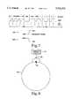
- FIG. 7is a timing diagram showing a suitable RF protocol for messages returned by the transponder
- FIG. 8is a schematic diagram of a pressure sensitive transponder circuit
- FIG. 9is a block diagram of a tire condition sensing system in which a low frequency modulation is added to the RF excitation signal to verify a return signal from the transponder;
- FIG. 10is a block diagram of a wheel condition sensing system in which a returned signal is verified by phase comparison.
- FIG. 11is a block diagram of a multi-wheel system in which a master exciter/receiver communicates with multiple wheel transponders.
- the inventioncan be used to communicate both tire identification and information on the tire condition to an off-tire location.
- a preferred embodimentis illustrated in FIG. 1, in which both the transponder antenna and identification/condition sensing mechanism are isolated from the extreme temperatures, mechanical stress and deflection to which the tire is subjected (except possibly for emergency conditions).
- a standard wheel assembly 2is shown, including a vehicle axle 4, a brake rotor 6 and calipers 8, and a set of wheel nuts 10 that hold the wheel onto the axle.
- a splash guard 12is positioned on the vehicle side of the wheel assembly to protect the calipers and rotor from water and dirt.
- An RF exciter/reader 14can be mounted to the splash guard adjacent the wheel assembly, or at any other convenient location on the vehicle which carries the wheel. Alternately, the exciter/reader can be placed at a fixed location off the vehicle to interrogate the wheels of passing vehicles.
- a tire 16is mounted to the wheel between peripheral wheel rims 18a and 18b.
- the wheel periphery 20has a reduced diameter between the rims, producing saddle which slopes upward on each side towards the opposed rims.
- a transponder systemis positioned in a flexible resilient tube 22 that extends around the wheel periphery.
- the tubeincludes a peripheral groove 24 that extends into its outer surface.
- a transponder antennawhich communicates identification and/or tire condition information to the exciter/receiver unit 14 is seated within the groove 24 and extends substantially all the way around the tube.
- the transponder antennacan either be single turn or multi-turn.
- the tubeis formed from a material, such as foam rubber or elastomer, that is flexible enough to be stretched out and passed over the outer wheel rim 18a when the tube is mounted, and resilient enough to thereafter seat the tube in place around the wheel periphery.
- the tube 22is preferably configured so that groove 24 extends above the height of the wheel rims 18a, thereby enhancing RF access to the transponder antenna 24.
- FIG. 3illustrates a multi-turn transponder antenna in which the antenna wire 26 (generally copper) is wound in multiple turns within the groove 24.
- Reinforcing cords 28, formed from a material such as Dacron® or nylon string,can be wound around the base of the groove 24 to protect the antenna coil, while a sealant 30 is applied over the outermost coils.
- the exciter/reader 14transmits an RF signal that is picked up by the transponder antenna 26 and delivered to a circuit element that is also lodged in the tube.
- the circuit elementcan provide either a tire identification code or information about a tire condition, or both.
- an integrated circuit (IC) chip 32is shown lodged in a recess 34 in the outer tube surface that opens into the groove 24.
- the chip 32is connected to the antenna coil 26, and is actuated by an RF interrogation signal from the exciter/reader 14 to transmit the desired information back to the exciter/reader through the same coil 26.
- transponder and its coilin this manner has several advantages over conventional transponders, which are typically mounted to the tire itself and employ small dipole antennas or coils. No modification to either the tire or the wheel is required to install the transponder, and communication is possible whether the vehicle is stationary or in motion. Since the transponder/antenna assembly is not mounted permanently, it can easily be replaced if it is damaged. Both the transponder assembly and the exciter/reader are noninvasive to the vehicle, increasing their attractiveness to the after market.
- the inner diameter of the tube groove 24is made slightly larger than the diameter of the outer wheel rim 18a. This allows the tube to be slipped over the rim without unduly stressing the antenna.
- the tubeis preferably formed from a material that is quite deformable, such as a low density foam, so that the portion of the tube below the groove easily deforms and passes over the wheel rim in mounting the tube.
- FIG. 5illustrates another embodiment of the invention, intended particularly for a single turn antenna, in which the antenna 36 is formed from a stiffly flexible material such as 16 gage spring steel wire, and has a diameter that varies around the coil.
- the antenna 36has an undulating shape, with its outer sections 36a extending slightly above the level of the wheel rim 18a, and its inner sections 36b bearing against the wheel periphery 20.
- the major diameter lobes 36a that extend above the rim 18areceive the signal from the exciter/reader, while the minor diameter lobes 36b can be insulated from the wheel by coating them with a plastic material such as the coating used on tool handles.
- To mount the antenna 36 on a wheelit is mechanically distorted enough to pass over the wheel rim 18a, and springs back to its original shape, which holds it in place around the wheel periphery 20.
- the IC chip 32can generate a tire identification code in a conventional manner, such as that described in U.S. Pat. No. 4,730,188 to Milheiser.
- a suitable communications systemsimilar to that described in the Milheiser patent, is shown in block diagram form in FIG. 6.
- Various available exciter/receiverscan be used, such as the MINIPROX® reader by Hughes Identification Devices, Inc., mechanically reconfigured to be mounted on a vehicle splash guard or other convenient location. It is shown as consisting of three main functional units: an exciter 38, signal conditioner 40 and demodulation and detection circuits 42.
- the exciter 38consists of an AC signal source 44, followed by a power driver 46 which provides a high current, high voltage excitation signal to an interrogator antenna coil 48 through a capacitor 50.
- the interrogator coil 48 and the capacitor 50are selected to resonate at the excitation signal frequency, so that the voltage across the coil is much greater than the voltage output from the driver.
- the signal conditioner 40connects to the interrogator coil 48 and serves to amplify the identification signal returned from the transponder, while filtering out the excitation signal frequency as well as other noise and undesired signals outside the frequency range used by the transponder signals. It includes a bandpass filter/bandstop filter 51 that actively passes the identification code signal frequencies returned from the transponder and passively excludes the high energy at the excitation frequency, and an amplifier 52.
- the amplified output of the signal conditioner 40is fed to the demodulation and detection unit 42, which includes a frequency shift keyed (FSK) demodulator 54 and a microcomputer 56.
- the FSK demodulator 54is a phase-locked loop circuit configured as a tone decoder which gives a digital output as the signal from the transponder shifts between two frequencies.
- the microcomputer 56extracts the identification code from this digital output by observing the timing of transitions between the two logic levels.
- the identification code obtained by the microcomputer 56can be transferred to a display or printer, sent over communication lines to a remote point, stored on tape, disk or other storage medium, or sent to another computer.
- the transponderincludes the antenna coil 26, which is located such that the magnetic flux generated by the interrogator coil 48 couples energy at the exciter frequency into the transponder. This energy is converted to a DC voltage using a full-wave rectifier bridge 58 and a smoothing capacitor 60, as is commonly used in power supply circuits. This DC voltage supplies the power to a control logic and identification memory circuit 62.
- the logic control 62aconsists of counters and gates which sequentially read out the contents of the identification memory 62b.
- the logic 62aalso inserts a sync word into the signal data stream to allow the exciter/reader to synchronize to the data.
- the excitation signal which appears on the transponder coil 26is supplied to the control logic to provide a clock signal.
- the control logic circuit 62aconverts the serial data and sync stream into a frequency shift keyed (FSK) waveform which is connected to the transponder coil 26 through complementary current syncs to transmit the FSK identification signal.
- the transmitted signalis received by the interrogator coil 48 due to the mutual inductance between it and transponder coil 26, and is amplified by the signal conditioner and detected.
- the components of the exciter/reader 14can be implemented as either different units which are connected to one another, or wired together as a single unit.
- FIG. 7illustrates a suitable protocol, as described in the Milheiser patent. Reading from top to bottom, FIG. 7 shows the serial digital data stream comprising the coded message, the signal frequency, the spacing of the bit periods, the distinction between the sync or preamble portions of the signal and the data, and a Manchester encoding scheme used by the transponder.
- the data streamconsists of a total of 48 bit periods.
- Datais encoded using the Manchester encoding technique commonly employed in serial data transmissions. In the Manchester technique, data values are represented by transitions from a low to high level or high to low level in the middle of the bit period.
- synchronizationinformation is contained in the first eight bit periods of the data stream.
- the syncconsists of four bit periods of preamble information followed by a constant low level for one and a half bit periods, a constant high level for one and a half bit periods and a zero data bit.
- the eight sync bit periodsare followed by forty bit periods containing the actual identification data. Exemplary data corresponding to "11001 . . .” is shown. The circuit runs continuously during interrogation such that an endless stream of sync followed by data appears.
- FIG. 8Another embodiment of the invention, which can be used to transmit information on a tire condition such as air pressure, temperature, etc., is illustrated in FIG. 8. It is known that a coil connected in series with a diode will return a signal of double the frequency of an interrogation signal that has been coupled to the coil. This concept is commonly used in simple "here-I-am" tags that are secured to garments in department stores to protect against theft. If the tag is not removed, its frequency doubling is detected by an exciter/reader which the customer must pass to exit the store, and initiates an alarm. This type of circuit is described, for example, in U.S. Pat. No. 4,063,229 to Welsh et al. (FIGS. 17 and 18).
- the present inventionexpands upon this basic operating principal to provide a tire transponder that affirmatively indicates whether a particular tire condition has crossed a preset threshold level, rather than the passive "here-I-am" operation of prior systems.
- the new approachcan be used to activate an alarm within the vehicle when the pressure within a tire has dropped so far as to indicate that the tire has gone flat, or at least needs to be recharged with air.
- the transponderincludes a diode 64 that is connected in series with a transponder antenna 66, which is illustrated as a single turn antenna that can be mounted around a vehicle wheel using any of the techniques described above.
- a suitable diode for this purposehas the industry designation 1N914.
- a switch 68is connected in parallel with the diode, such that the diode is bypassed and short circuited when the switch is closed.
- the switchis controlled by a condition sensor 70, which for example can be integrated with the switch as a pressure actuated device that closes at a predetermined air pressure; such pressure switches are common in automotive applications.
- the exciter/readeris designed to look for a return signal with a frequency twice the interrogation signal frequency.
- the switchis open and the transponder returns a signal at twice the interrogation frequency; this is recognized by the exciter/reader as indicating a satisfactory tire pressure.
- the sensor 70closes switch 68 to bypass the diode. This removes the return double-frequency signal, causing a low tire pressure alarm within the vehicle to be activated.
- the transpondercan be configured so that the switch is closed when the tire pressure is above the threshold level, and open when the pressure falls below. In this case the low pressure alarm would be activated by the presence of a returned double-frequency signal.
- pressure sensorscommonly operate at the same threshold level regardless of the direction of the pressure change (i.e., regardless of whether the pressure falls through the threshold or rises above it), this type of symmetrical operation is not necessary for the invention.
- the pressure sensorcan include a degree of hysteresis, so long as it initiates the low pressure alarm when the tire pressure falls below the desired threshold level.
- the resonant frequency of the transponder coilwill vary with its inductance and capacitance in accordance with the usual inverse relationship to 2 ⁇ LC, where L and C are the coil's inductance and capacitance, respectively.
- the inductancein turn, varies with the square of the number of turns (corrected for the coil's aspect ratio).
- the exciter/readercan operate at a frequency of 125 KHz, which is well within the 110-300 KHz range that is accepted world-wide for this purpose.
- a single turn transponder antenna as illustrated in FIG. 8will typically operate at 27 MHz, which is still much lower than the high frequency previously used, and requires less expensive equipment.
- the tire condition sensing systembased upon a double frequency return signal, it may be desirable to protect the system from a double frequency signal source other than the tire transponder itself. For example, it would be very undesirable for a prankster to be able to cause a parking lot full of similar vehicles to show flat tires by broadcasting a double frequency signal. This situation can be prevented by modulating the excitation signal with a low frequency signal. The double frequency return signal is then correlated with the low frequency signal so that only a return signal that was stimulated by the original excitation signal would be considered.
- the RF reader/exciter 14which is assumed to transmit a 27 MHz interrogation signal, receives a relatively low frequency modulation such as 100 KHz.
- the resultis a 27 MHz interrogation signal 72 modulated by a 100 KHz envelope 74.
- the 100 KHz signalis also fed through a frequency doubler 76 to provide a 200 KHz input to a mixer 78.
- a frequency-doubled return signal from the transponder associated with the exciter/readerwill have a principal 54 MHz component 80, with a 200 KHz modulation 82. If the transmitted and returned signals are in phase, which would be the case for a return signal stimulated by the exciter signal, the mixer produces an amplified output 84. If the return signal does not have a low frequency modulation in phase with the transmitted signal, the mixer will produce zero or very little output.
- FIG. 10Another approach that can be used instead of or in addition to the low frequency modulation, to verify that the return signal originated from the transponder circuit, is shown in FIG. 10. It employs a synchronous detection scheme which uses the excitation signal as a clock for removing unwanted signals that have the same (or double) frequency but are out of phase. It is illustrated as a phase comparator 86 that receives an RF input from the exciter/reader 14, and a comparison return input 88. If the two inputs to the comparator are in phase, a functional output 90 is produced. If the two inputs are out of phase, indicating that the return signal did not originate from the desired transponder, no output is produced from the phase comparator.
- a phase comparator 86receives an RF input from the exciter/reader 14, and a comparison return input 88. If the two inputs to the comparator are in phase, a functional output 90 is produced. If the two inputs are out of phase, indicating that the return signal did not originate from the desired transponder, no
- FIG. 11A further improvement is illustrated in FIG. 11.
- the electrical circuitry for a single exciter/reader 92is provided at a suitable location within the vehicle, and used to communicate with transponders (not shown) on each of the vehicle's wheel assemblies 2a-2d.
- the output of the exciter/reader 92is time shared between corresponding antenna coils 48a-48d adjacent each of the wheel sites. Only the antenna coils 48a-48d, and no electronics, are required at the localized wheel sites. This is facilitated by the extreme simplicity of the required signal protocol, and the large magnitude of the return signals.
- the exciter/reader 92communicates with one tire transponder at a time, deactivating a given transponder before moving on to the next.
- the bandwidth of the described communication systemis very high, and it is possible to communicate large amounts of data. This allows for high precision and the possibility of multiple data channels. Furthermore, cross talk between adjacent vehicles can be eliminated by superimposing a tire identification code onto a tire condition signal from a wheel transponder.
Landscapes
- Engineering & Computer Science (AREA)
- Mechanical Engineering (AREA)
- Computer Networks & Wireless Communication (AREA)
- Computer Hardware Design (AREA)
- Microelectronics & Electronic Packaging (AREA)
- Physics & Mathematics (AREA)
- General Physics & Mathematics (AREA)
- Theoretical Computer Science (AREA)
- Measuring Fluid Pressure (AREA)
- Arrangements For Transmission Of Measured Signals (AREA)
Abstract
Description
Claims (35)
Priority Applications (1)
| Application Number | Priority Date | Filing Date | Title |
|---|---|---|---|
| US08/173,381US5541574A (en) | 1993-12-22 | 1993-12-22 | Transponder system for communicating with a vehicle tire |
Applications Claiming Priority (1)
| Application Number | Priority Date | Filing Date | Title |
|---|---|---|---|
| US08/173,381US5541574A (en) | 1993-12-22 | 1993-12-22 | Transponder system for communicating with a vehicle tire |
Publications (1)
| Publication Number | Publication Date |
|---|---|
| US5541574Atrue US5541574A (en) | 1996-07-30 |
Family
ID=22631748
Family Applications (1)
| Application Number | Title | Priority Date | Filing Date |
|---|---|---|---|
| US08/173,381Expired - Fee RelatedUS5541574A (en) | 1993-12-22 | 1993-12-22 | Transponder system for communicating with a vehicle tire |
Country Status (1)
| Country | Link |
|---|---|
| US (1) | US5541574A (en) |
Cited By (77)
| Publication number | Priority date | Publication date | Assignee | Title |
|---|---|---|---|---|
| US5661651A (en)* | 1995-03-31 | 1997-08-26 | Prince Corporation | Wireless vehicle parameter monitoring system |
| US5764138A (en)* | 1994-04-29 | 1998-06-09 | Hid Corporation | RF identification system for providing static data and one bit of variable data representative of an external stimulus |
| US5867093A (en)* | 1996-10-02 | 1999-02-02 | Identec Limited | Communication system for vehicles with aerial incorporated in steering wheel |
| WO1999029522A1 (en)* | 1997-12-09 | 1999-06-17 | The Goodyear Tire & Rubber Company | Pneumatic tyre with an antenna for radio transponder |
| US5992739A (en)* | 1996-08-09 | 1999-11-30 | Ferag Ag | Movable object carrying electronically stored data to be read and or/overwritten by a non-contact reading/writing device |
| WO2000002741A1 (en) | 1998-07-10 | 2000-01-20 | The Goodyear Tire & Rubber Company | Self-powered tire revolution counter |
| US6025783A (en)* | 1998-04-30 | 2000-02-15 | Trw Vehicle Safety Systems Inc. | Wireless switch detection system |
| US6194999B1 (en)* | 1995-05-26 | 2001-02-27 | UHL GüNTER | Device fitted on vehicles for monitoring tyre pressure |
| US6204758B1 (en)* | 1999-07-23 | 2001-03-20 | Schrader-Bridgeport International, Inc. | System to automatically determine wheel position for automotive remote tire monitoring system |
| FR2812436A1 (en)* | 2000-07-31 | 2002-02-01 | Michelin Soc Tech | Monitoring system for vehicle wheels includes interrogation device on vehicle and transponder units mounted in tyres |
| WO2002007993A3 (en)* | 2000-07-26 | 2002-04-25 | Bridgestone Firestone Inc | Electronic tire management system |
| WO2002038400A1 (en)* | 2000-11-13 | 2002-05-16 | Societe De Technologie Michelin | Safety insert with incorporated transmission antenna |
| WO2002048981A1 (en)* | 2000-12-15 | 2002-06-20 | Eastern Ribbon And Roll Corp. | Paper roll anti-theft protection |
| US6430484B1 (en)* | 1999-10-06 | 2002-08-06 | Toyota Jidosha Kabushiki Kaisha | Vehicle wheel information supply device which supplies smaller data set earlier than larger data set |
| US6441728B1 (en)* | 2001-01-02 | 2002-08-27 | Trw Inc. | Tire condition sensor communication with tire location provided via vehicle-mounted identification units |
| EP1242257A1 (en)* | 1999-12-20 | 2002-09-25 | Transense Technologies PLC | Tyre condition monitoring system |
| US20020133942A1 (en)* | 2001-03-20 | 2002-09-26 | Kenison Michael H. | Extended life electronic tags |
| WO2002083436A1 (en)* | 2001-04-12 | 2002-10-24 | Siemens Vdo Automotive Corporation | Sensor mounting assembly for a vehicle tire |
| US6474380B1 (en)* | 1999-04-29 | 2002-11-05 | Bridgestone/Firestone North American Tire, Llc | Pneumatic tire and monitoring device including dipole antenna |
| US6486776B1 (en)* | 1998-04-14 | 2002-11-26 | The Goodyear Tire & Rubber Company | RF transponder and method of measuring parameters associated with a monitored object |
| US20020190853A1 (en)* | 2000-12-05 | 2002-12-19 | Trw France Sa | Measuring system for wheel parameters and measuring detector for such a system |
| US20030016126A1 (en)* | 2001-06-28 | 2003-01-23 | Pacific Industrial Co., Ltd. | Tire condition monitoring apparatus |
| WO2003000509A3 (en)* | 2001-06-25 | 2003-04-10 | 3Dm Technologies Inc | Tire sensor |
| US6581449B1 (en) | 1999-09-15 | 2003-06-24 | The Goodyear Tire & Rubber Company | Low pressure warning system for pneumatic tires with RF tags and monitors for each tire |
| EP1344658A1 (en)* | 2002-03-12 | 2003-09-17 | Siemens Aktiengesellschaft | Device for obtaining the tyre pressure of a vehicle tyre |
| US20030182996A1 (en)* | 2000-08-16 | 2003-10-02 | Bankart Adrian Edmund | Tyre condition indicating apparatus |
| WO2003105511A1 (en)* | 2002-06-11 | 2003-12-18 | Societe De Technologie Michelin | A method for embedding a radio frequency antenna in a tire |
| WO2004000579A1 (en)* | 2002-06-21 | 2003-12-31 | Bridgestone Corporation | Tired wheel with tire-information sending body, installation instrument and fixing instrument for tire-information sending body, and method of installing tire-information sending body |
| EP1384603A1 (en)* | 2002-07-24 | 2004-01-28 | The Goodyear Tire & Rubber Company | Annular antenna and transponder apparatus and method of disposition in pneumatic tires |
| US20040027241A1 (en)* | 2002-08-08 | 2004-02-12 | Forster Ian J. | Vehicle tag reader |
| US20040155764A1 (en)* | 2003-02-10 | 2004-08-12 | Honda Motor Co., Ltd. | Tire pressure detection system and a wheel used therein |
| US20040206168A1 (en)* | 2003-04-18 | 2004-10-21 | Michiya Katou | Tire condition monitoring apparatus |
| US6809637B1 (en) | 1999-09-03 | 2004-10-26 | The Goodyear Tire & Rubber Company | Monitoring a condition of a pneumatic tire |
| US20040236755A1 (en)* | 2000-05-05 | 2004-11-25 | Christian Odemann | Method for the management of aeronautical industry implements to be checked |
| EP1522471A1 (en)* | 2003-06-17 | 2005-04-13 | Tien-Tsai Huang | Multifunction car theft alarm lock with tire pressure sensing device |
| US20050093761A1 (en)* | 2002-08-14 | 2005-05-05 | King Patrick F. | RFID tire belt antenna system and method |
| US20050099283A1 (en)* | 2002-12-16 | 2005-05-12 | The Goodyear Tire & Rubber Company | Coupled transponder and antenna system and method |
| US20050121518A1 (en)* | 2003-12-05 | 2005-06-09 | Steffen Dale A. | Low voltage signal stripping circuit for an RFID reader |
| US20050133131A1 (en)* | 2003-12-22 | 2005-06-23 | Starinshak Thomas W. | High elongation antenna assembly and method for a tire |
| US20050146424A1 (en)* | 2003-12-12 | 2005-07-07 | Barbanti Giovanni | System for transmitting a signal indicating the functioning condition of a tire |
| WO2005063512A1 (en)* | 2003-12-23 | 2005-07-14 | Robert Bosch Gmbh | Device for detecting and transmitting measuring a signal that represents the condition of a pneumatic tire |
| US20050151634A1 (en)* | 2004-01-09 | 2005-07-14 | Denso Corporation | Tire condition monitoring system |
| US20050188757A1 (en)* | 2004-02-27 | 2005-09-01 | Trw Automotive U.S. Llc | Tire parameter sensing system having a magnetically conductive rim and an associated method |
| US20050242939A1 (en)* | 2004-04-30 | 2005-11-03 | Andreas Hagl | Tire pressure monitoring system |
| US20050258966A1 (en)* | 2004-05-18 | 2005-11-24 | Quan Ralph W | Antenna array for an RFID reader compatible with transponders operating at different carrier frequencies |
| US20050258940A1 (en)* | 2004-05-18 | 2005-11-24 | Quan Ralph W | RFID reader utilizing an analog to digital converter for data acquisition and power monitoring functions |
| US20060065730A1 (en)* | 2004-09-24 | 2006-03-30 | Quan Ralph W | RFID system having a field reprogrammable RFID reader |
| KR100623751B1 (en) | 2004-09-13 | 2006-09-19 | 기아자동차주식회사 | Cross-talk prevention device of tire pressure monitoring system |
| US7161476B2 (en) | 2000-07-26 | 2007-01-09 | Bridgestone Firestone North American Tire, Llc | Electronic tire management system |
| CN1313292C (en)* | 2002-04-02 | 2007-05-02 | 米其林技术公司 | Tyre with a receiving antenna |
| US20070108273A1 (en)* | 2004-04-23 | 2007-05-17 | Winware, Inc. | Object Tracking in an Enclosure |
| US20070115127A1 (en)* | 2004-04-23 | 2007-05-24 | Winware, Inc. | RFID Switching |
| US20070194895A1 (en)* | 2006-02-23 | 2007-08-23 | Dymos Co., Ltd. D/B/A Dymos Of America | Tire pressure monitoring system and sensor therefor |
| US20070229273A1 (en)* | 2006-03-31 | 2007-10-04 | Hoemann James D | Detection signal generator circuit for an RFID reader |
| US20070236336A1 (en)* | 2006-03-31 | 2007-10-11 | Borcherding Eric J | Transponder detector for an RFID system generating a progression of detection signals |
| US20080065290A1 (en)* | 2000-09-08 | 2008-03-13 | Automotive Technologies International, Inc. | Component Monitoring System |
| CN100375985C (en)* | 2000-08-08 | 2008-03-19 | 施耐德电器工业公司 | Electric equipment, supporting body of electric switch equipment and monitor equipment, and electric equipment including these |
| US20080088415A1 (en)* | 2006-10-16 | 2008-04-17 | Quan Ralph W | Tuning an RFID reader with electronic switches |
| US20090170433A1 (en)* | 2007-12-28 | 2009-07-02 | Mark Rhodes | Inductive communications system |
| US20090234249A1 (en)* | 2008-03-13 | 2009-09-17 | Larry Tab Randolph | Pressure switches, transmitters, systems, and methods for monitoring a pressure at a tissue site |
| US20090237223A1 (en)* | 2008-03-24 | 2009-09-24 | Intermec Ip Corp. | Rfid tag communication triggered by sensed energy |
| US20090251291A1 (en)* | 2008-04-01 | 2009-10-08 | Assa Abloy Ab | Switched capacitance method for the detection of, and subsequent communication with a wireless transponder device using a single antenna |
| CN100584646C (en)* | 2004-08-21 | 2010-01-27 | 三星Techwin株式会社 | Vehicle tire with RFID tag |
| US20120049620A1 (en)* | 2009-05-11 | 2012-03-01 | Koninklijke Philips Electronics N.V. | Inductive power transfer for wireless sensor systems inside a tyre |
| US8266465B2 (en) | 2000-07-26 | 2012-09-11 | Bridgestone Americas Tire Operation, LLC | System for conserving battery life in a battery operated device |
| US8718868B2 (en) | 2011-06-30 | 2014-05-06 | GM Global Technology Operations LLC | Vehicle using tire temperature to adjust active chassis systems |
| US20140368327A1 (en)* | 2013-06-13 | 2014-12-18 | Infineon Technologies Ag | RFID-tag, a TPMS Device, a Tire, a Receiver Device and a Method for Providing Information related to Identification of a Tire |
| USRE45917E1 (en)* | 2010-06-22 | 2016-03-08 | Korea Advanced Institute Of Science And Technology | Throw type compact reconnaissance robot |
| DE102016214089A1 (en)* | 2016-07-29 | 2018-02-01 | Alligator Ventilfabrik Gmbh | Fastening device for fastening a measuring sensor, in particular tire pressure sensor |
| US20180094996A1 (en)* | 2016-09-30 | 2018-04-05 | Cub Elecparts Inc. | Data transmitting device capable of configuring different operating frequencies for use by tire pressure monitoring detector |
| US20200360802A1 (en)* | 2019-05-14 | 2020-11-19 | Stmicroelectronics Kk | Device, for example video game device, provided with a contactless transponder |
| CN112203873A (en)* | 2018-03-30 | 2021-01-08 | 米其林集团总公司 | Radio frequency transponder for tire |
| US10913315B1 (en) | 2019-05-13 | 2021-02-09 | Unicus Innovations Llc | Self contained tire inflator |
| US11186254B2 (en)* | 2017-12-06 | 2021-11-30 | Bridgestone Corporation | Tire theft monitoring system, tire theft monitoring apparatus, and tire theft monitoring method |
| US11571936B1 (en) | 2019-05-13 | 2023-02-07 | Unicus Innovations Llc | Self contained tire inflator |
| US20230077614A1 (en)* | 2021-09-10 | 2023-03-16 | 2T Technologies, LLC | Tubing RFID Systems and Methods |
| US11641053B2 (en) | 2019-07-19 | 2023-05-02 | The Goodyear Tire & Rubber Company | Reader system for tire with an integrated RFID and TPMS sensor |
Citations (10)
| Publication number | Priority date | Publication date | Assignee | Title |
|---|---|---|---|---|
| US4063229A (en)* | 1967-03-30 | 1977-12-13 | Sensormatic Electronics Corporation | Article surveillance |
| US4074227A (en)* | 1974-11-15 | 1978-02-14 | Kalmus Henry P | Tire pressure indicator |
| GB2016383A (en)* | 1978-11-21 | 1979-09-26 | Pappas D G | Tire-pressure alarm system and wheel unit therefor |
| US4319220A (en)* | 1976-08-31 | 1982-03-09 | Dennis G. Pappas | Alarm system for monitoring pressurized vehicular tires |
| US4409586A (en)* | 1981-05-26 | 1983-10-11 | Hochstein Peter A | Tire condition monitor converter |
| US4507956A (en)* | 1983-09-09 | 1985-04-02 | Eaton Corporation | Circuit mounting apparatus |
| US4730188A (en)* | 1984-02-15 | 1988-03-08 | Identification Devices, Inc. | Identification system |
| US4953393A (en)* | 1986-07-04 | 1990-09-04 | Philip Elliot Galasko | Transducer |
| US5196845A (en)* | 1988-10-24 | 1993-03-23 | Compagnie Generale Des Etablissements Michelin | Antenna for tire monitoring device |
| US5218861A (en)* | 1991-03-27 | 1993-06-15 | The Goodyear Tire & Rubber Company | Pneumatic tire having an integrated circuit transponder and pressure transducer |
- 1993
- 1993-12-22USUS08/173,381patent/US5541574A/ennot_activeExpired - Fee Related
Patent Citations (10)
| Publication number | Priority date | Publication date | Assignee | Title |
|---|---|---|---|---|
| US4063229A (en)* | 1967-03-30 | 1977-12-13 | Sensormatic Electronics Corporation | Article surveillance |
| US4074227A (en)* | 1974-11-15 | 1978-02-14 | Kalmus Henry P | Tire pressure indicator |
| US4319220A (en)* | 1976-08-31 | 1982-03-09 | Dennis G. Pappas | Alarm system for monitoring pressurized vehicular tires |
| GB2016383A (en)* | 1978-11-21 | 1979-09-26 | Pappas D G | Tire-pressure alarm system and wheel unit therefor |
| US4409586A (en)* | 1981-05-26 | 1983-10-11 | Hochstein Peter A | Tire condition monitor converter |
| US4507956A (en)* | 1983-09-09 | 1985-04-02 | Eaton Corporation | Circuit mounting apparatus |
| US4730188A (en)* | 1984-02-15 | 1988-03-08 | Identification Devices, Inc. | Identification system |
| US4953393A (en)* | 1986-07-04 | 1990-09-04 | Philip Elliot Galasko | Transducer |
| US5196845A (en)* | 1988-10-24 | 1993-03-23 | Compagnie Generale Des Etablissements Michelin | Antenna for tire monitoring device |
| US5218861A (en)* | 1991-03-27 | 1993-06-15 | The Goodyear Tire & Rubber Company | Pneumatic tire having an integrated circuit transponder and pressure transducer |
Cited By (145)
| Publication number | Priority date | Publication date | Assignee | Title |
|---|---|---|---|---|
| US5764138A (en)* | 1994-04-29 | 1998-06-09 | Hid Corporation | RF identification system for providing static data and one bit of variable data representative of an external stimulus |
| US5661651A (en)* | 1995-03-31 | 1997-08-26 | Prince Corporation | Wireless vehicle parameter monitoring system |
| US6194999B1 (en)* | 1995-05-26 | 2001-02-27 | UHL GüNTER | Device fitted on vehicles for monitoring tyre pressure |
| US6488212B1 (en) | 1996-08-09 | 2002-12-03 | Ferag Ag | System for identifying and locating relative positions of objects |
| US5992739A (en)* | 1996-08-09 | 1999-11-30 | Ferag Ag | Movable object carrying electronically stored data to be read and or/overwritten by a non-contact reading/writing device |
| US5867093A (en)* | 1996-10-02 | 1999-02-02 | Identec Limited | Communication system for vehicles with aerial incorporated in steering wheel |
| WO1999029522A1 (en)* | 1997-12-09 | 1999-06-17 | The Goodyear Tire & Rubber Company | Pneumatic tyre with an antenna for radio transponder |
| US6486776B1 (en)* | 1998-04-14 | 2002-11-26 | The Goodyear Tire & Rubber Company | RF transponder and method of measuring parameters associated with a monitored object |
| US6025783A (en)* | 1998-04-30 | 2000-02-15 | Trw Vehicle Safety Systems Inc. | Wireless switch detection system |
| DE19919158C2 (en)* | 1998-04-30 | 2002-05-23 | Trw Vehicle Safety Systems | Wireless switch detection system |
| WO2000002741A1 (en) | 1998-07-10 | 2000-01-20 | The Goodyear Tire & Rubber Company | Self-powered tire revolution counter |
| US6438193B1 (en) | 1998-07-10 | 2002-08-20 | Wen H. Ko | Self-powered tire revolution counter |
| US6474380B1 (en)* | 1999-04-29 | 2002-11-05 | Bridgestone/Firestone North American Tire, Llc | Pneumatic tire and monitoring device including dipole antenna |
| US6204758B1 (en)* | 1999-07-23 | 2001-03-20 | Schrader-Bridgeport International, Inc. | System to automatically determine wheel position for automotive remote tire monitoring system |
| US6809637B1 (en) | 1999-09-03 | 2004-10-26 | The Goodyear Tire & Rubber Company | Monitoring a condition of a pneumatic tire |
| US6581449B1 (en) | 1999-09-15 | 2003-06-24 | The Goodyear Tire & Rubber Company | Low pressure warning system for pneumatic tires with RF tags and monitors for each tire |
| US6430484B1 (en)* | 1999-10-06 | 2002-08-06 | Toyota Jidosha Kabushiki Kaisha | Vehicle wheel information supply device which supplies smaller data set earlier than larger data set |
| EP1242257A1 (en)* | 1999-12-20 | 2002-09-25 | Transense Technologies PLC | Tyre condition monitoring system |
| US7496587B2 (en)* | 2000-05-05 | 2009-02-24 | EDOMAT (Deutschland) Treuhand- und Vermögensverwaltungsgesellschaft mbH | Method for the management of aeronautical industry implements to be checked |
| US20040236755A1 (en)* | 2000-05-05 | 2004-11-25 | Christian Odemann | Method for the management of aeronautical industry implements to be checked |
| JP2015027877A (en)* | 2000-07-26 | 2015-02-12 | ブリヂストン アメリカス タイヤ オペレーションズ・エルエルシー | Tire electronic management system |
| US8266465B2 (en) | 2000-07-26 | 2012-09-11 | Bridgestone Americas Tire Operation, LLC | System for conserving battery life in a battery operated device |
| JP2011225215A (en)* | 2000-07-26 | 2011-11-10 | Bridgestone Firestone Inc | Electronic tire management system |
| WO2002007993A3 (en)* | 2000-07-26 | 2002-04-25 | Bridgestone Firestone Inc | Electronic tire management system |
| US7739529B2 (en)* | 2000-07-26 | 2010-06-15 | Bridgestone Americas Tire Operations, Llc | System for conserving battery life in a battery operated device |
| US20070135179A1 (en)* | 2000-07-26 | 2007-06-14 | Hardman Gordon E | System for conserving battery life in a battery operated device |
| US7161476B2 (en) | 2000-07-26 | 2007-01-09 | Bridgestone Firestone North American Tire, Llc | Electronic tire management system |
| US8151127B2 (en) | 2000-07-26 | 2012-04-03 | Bridgestone Americas Tire Operations, Llc | System for conserving battery life in a battery operated device |
| FR2812436A1 (en)* | 2000-07-31 | 2002-02-01 | Michelin Soc Tech | Monitoring system for vehicle wheels includes interrogation device on vehicle and transponder units mounted in tyres |
| CN100375985C (en)* | 2000-08-08 | 2008-03-19 | 施耐德电器工业公司 | Electric equipment, supporting body of electric switch equipment and monitor equipment, and electric equipment including these |
| US20030182996A1 (en)* | 2000-08-16 | 2003-10-02 | Bankart Adrian Edmund | Tyre condition indicating apparatus |
| US20080065290A1 (en)* | 2000-09-08 | 2008-03-13 | Automotive Technologies International, Inc. | Component Monitoring System |
| FR2816549A1 (en)* | 2000-11-13 | 2002-05-17 | Michelin Soc Tech | Remote monitoring road wheel safety insert having circumferential base wheel rim contacting and housing receiving wheel module with safety insert having integral antenna |
| US20040011446A1 (en)* | 2000-11-13 | 2004-01-22 | Michelin Recherche Et Technique S.A. | Safety insert with incorporated transmission antenna |
| WO2002038400A1 (en)* | 2000-11-13 | 2002-05-16 | Societe De Technologie Michelin | Safety insert with incorporated transmission antenna |
| US6853297B2 (en) | 2000-11-13 | 2005-02-08 | Michelin Recherche Et Technique S.A. | Safety insert with incorporated transmission antenna |
| US20020190853A1 (en)* | 2000-12-05 | 2002-12-19 | Trw France Sa | Measuring system for wheel parameters and measuring detector for such a system |
| US7021132B2 (en) | 2000-12-05 | 2006-04-04 | Trw France Sa | Measuring system for wheel parameters and measuring detector for such a system |
| WO2002048981A1 (en)* | 2000-12-15 | 2002-06-20 | Eastern Ribbon And Roll Corp. | Paper roll anti-theft protection |
| US6653940B2 (en)* | 2000-12-15 | 2003-11-25 | Eastern Ribbon & Roll Corp. | Paper roll anti-theft protection |
| US20040145479A1 (en)* | 2000-12-15 | 2004-07-29 | Collura Blaise J | Paper roll anti-theft protection |
| US6441728B1 (en)* | 2001-01-02 | 2002-08-27 | Trw Inc. | Tire condition sensor communication with tire location provided via vehicle-mounted identification units |
| US20020133942A1 (en)* | 2001-03-20 | 2002-09-26 | Kenison Michael H. | Extended life electronic tags |
| US6631637B2 (en) | 2001-04-12 | 2003-10-14 | Siemens Vdo Automotive Corporation | Sensor mounting assembly for a vehicle tire |
| WO2002083436A1 (en)* | 2001-04-12 | 2002-10-24 | Siemens Vdo Automotive Corporation | Sensor mounting assembly for a vehicle tire |
| US20040212486A1 (en)* | 2001-06-25 | 2004-10-28 | Dinello Panfilo M. | Tire sensor |
| US7034672B2 (en) | 2001-06-25 | 2006-04-25 | Global Tech International, Inc. | Tire sensor |
| WO2003000509A3 (en)* | 2001-06-25 | 2003-04-10 | 3Dm Technologies Inc | Tire sensor |
| US20030016126A1 (en)* | 2001-06-28 | 2003-01-23 | Pacific Industrial Co., Ltd. | Tire condition monitoring apparatus |
| US6861950B2 (en)* | 2001-06-28 | 2005-03-01 | Pacific Industrial Co., Ltd. | Tire condition monitoring apparatus |
| EP1344658A1 (en)* | 2002-03-12 | 2003-09-17 | Siemens Aktiengesellschaft | Device for obtaining the tyre pressure of a vehicle tyre |
| CN1313292C (en)* | 2002-04-02 | 2007-05-02 | 米其林技术公司 | Tyre with a receiving antenna |
| WO2003105511A1 (en)* | 2002-06-11 | 2003-12-18 | Societe De Technologie Michelin | A method for embedding a radio frequency antenna in a tire |
| US20050242937A1 (en)* | 2002-06-21 | 2005-11-03 | Bridgestone Corporation | Tired wheel with tire-information sending body, installation instrument and fixing instrument for tire-information sending body, and method of installing tire-information sending body |
| WO2004000579A1 (en)* | 2002-06-21 | 2003-12-31 | Bridgestone Corporation | Tired wheel with tire-information sending body, installation instrument and fixing instrument for tire-information sending body, and method of installing tire-information sending body |
| JP2004058997A (en)* | 2002-07-24 | 2004-02-26 | Goodyear Tire & Rubber Co:The | Annular antenna and transponder device, and method for disposing them in pneumatic tire |
| EP1384603A1 (en)* | 2002-07-24 | 2004-01-28 | The Goodyear Tire & Rubber Company | Annular antenna and transponder apparatus and method of disposition in pneumatic tires |
| US20040016487A1 (en)* | 2002-07-24 | 2004-01-29 | Johnson David Allan | Coupled transponder and antenna system and method |
| US20040016488A1 (en)* | 2002-07-24 | 2004-01-29 | Benedict Robert Leon | Annular antenna and transponder apparatus and method of disposition in pneumatic tires |
| US20060170540A1 (en)* | 2002-08-08 | 2006-08-03 | Mineral Lassen Llc | Vehicle tag reader |
| US7586403B2 (en) | 2002-08-08 | 2009-09-08 | Ian J Forster | Vehicle tag reader |
| US20070013500A1 (en)* | 2002-08-08 | 2007-01-18 | Mineral Lassen Llc | Vehicle tag reader |
| US7518494B2 (en) | 2002-08-08 | 2009-04-14 | Ian J Forster | Vehicle tag reader |
| US7015802B2 (en) | 2002-08-08 | 2006-03-21 | Forster Ian J | Vehicle tag reader |
| US20040027241A1 (en)* | 2002-08-08 | 2004-02-12 | Forster Ian J. | Vehicle tag reader |
| EP1939018A1 (en) | 2002-08-08 | 2008-07-02 | Mineral Lassen LLC | Vehicle tag reader |
| US7479873B2 (en) | 2002-08-08 | 2009-01-20 | Mineral Lassen Llc | Vehicle tag reader |
| US20060192662A1 (en)* | 2002-08-08 | 2006-08-31 | Mineral Lassen Llc | Vehicle tag reader |
| US7050017B2 (en) | 2002-08-14 | 2006-05-23 | King Patrick F | RFID tire belt antenna system and method |
| US20050093761A1 (en)* | 2002-08-14 | 2005-05-05 | King Patrick F. | RFID tire belt antenna system and method |
| US20050099283A1 (en)* | 2002-12-16 | 2005-05-12 | The Goodyear Tire & Rubber Company | Coupled transponder and antenna system and method |
| US7019711B2 (en)* | 2002-12-16 | 2006-03-28 | The Goodyear Tire & Rubber Company | Coupled transponder and antenna system and method |
| US20040155764A1 (en)* | 2003-02-10 | 2004-08-12 | Honda Motor Co., Ltd. | Tire pressure detection system and a wheel used therein |
| US7091840B2 (en)* | 2003-02-10 | 2006-08-15 | Honda Motor Co., Ltd. | Tire pressure detection system and a wheel used therein |
| US6931923B2 (en)* | 2003-04-18 | 2005-08-23 | Pacific Industrial Co., Ltd. | Tire condition monitoring apparatus |
| US20040206168A1 (en)* | 2003-04-18 | 2004-10-21 | Michiya Katou | Tire condition monitoring apparatus |
| EP1522471A1 (en)* | 2003-06-17 | 2005-04-13 | Tien-Tsai Huang | Multifunction car theft alarm lock with tire pressure sensing device |
| US7124942B2 (en) | 2003-12-05 | 2006-10-24 | Hid Corporation | Low voltage signal stripping circuit for an RFID reader |
| US20070001008A1 (en)* | 2003-12-05 | 2007-01-04 | Hid Corporation | Low voltage signal stripping circuit for an RFID reader |
| US7559477B2 (en) | 2003-12-05 | 2009-07-14 | Assa Abloy Ab | Low voltage signal stripping circuit for an RFID reader |
| US20050121518A1 (en)* | 2003-12-05 | 2005-06-09 | Steffen Dale A. | Low voltage signal stripping circuit for an RFID reader |
| US20050146424A1 (en)* | 2003-12-12 | 2005-07-07 | Barbanti Giovanni | System for transmitting a signal indicating the functioning condition of a tire |
| US7104298B2 (en)* | 2003-12-22 | 2006-09-12 | The Goodyear Tire & Rubber Company | Tire having antenna attached to elastic fiber textile strip and method of mounting antenna assembly to tire |
| US20050133131A1 (en)* | 2003-12-22 | 2005-06-23 | Starinshak Thomas W. | High elongation antenna assembly and method for a tire |
| WO2005063512A1 (en)* | 2003-12-23 | 2005-07-14 | Robert Bosch Gmbh | Device for detecting and transmitting measuring a signal that represents the condition of a pneumatic tire |
| CN100354150C (en)* | 2004-01-09 | 2007-12-12 | 株式会社电装 | Tire condition monitoring system |
| US7202777B2 (en)* | 2004-01-09 | 2007-04-10 | Denso Corporation | Tire condition monitoring system |
| US20050151634A1 (en)* | 2004-01-09 | 2005-07-14 | Denso Corporation | Tire condition monitoring system |
| US6938468B1 (en) | 2004-02-27 | 2005-09-06 | Trw Automotive U.S. Llc | Tire parameter sensing system having a magnetically conductive rim and an associated method |
| US20050188757A1 (en)* | 2004-02-27 | 2005-09-01 | Trw Automotive U.S. Llc | Tire parameter sensing system having a magnetically conductive rim and an associated method |
| US20070115127A1 (en)* | 2004-04-23 | 2007-05-24 | Winware, Inc. | RFID Switching |
| US20070108273A1 (en)* | 2004-04-23 | 2007-05-17 | Winware, Inc. | Object Tracking in an Enclosure |
| US7753272B2 (en) | 2004-04-23 | 2010-07-13 | Winware, Inc. | Object tracking in an enclosure |
| US7378951B2 (en)* | 2004-04-30 | 2008-05-27 | Texas Instruments Incorporated | Tire pressure monitoring system |
| US20050242939A1 (en)* | 2004-04-30 | 2005-11-03 | Andreas Hagl | Tire pressure monitoring system |
| US7439862B2 (en) | 2004-05-18 | 2008-10-21 | Assa Abloy Ab | Antenna array for an RFID reader compatible with transponders operating at different carrier frequencies |
| US20050258940A1 (en)* | 2004-05-18 | 2005-11-24 | Quan Ralph W | RFID reader utilizing an analog to digital converter for data acquisition and power monitoring functions |
| US7180403B2 (en) | 2004-05-18 | 2007-02-20 | Assa Abloy Identification Technology Group Ab | RFID reader utilizing an analog to digital converter for data acquisition and power monitoring functions |
| US20050258966A1 (en)* | 2004-05-18 | 2005-11-24 | Quan Ralph W | Antenna array for an RFID reader compatible with transponders operating at different carrier frequencies |
| CN100584646C (en)* | 2004-08-21 | 2010-01-27 | 三星Techwin株式会社 | Vehicle tire with RFID tag |
| KR100623751B1 (en) | 2004-09-13 | 2006-09-19 | 기아자동차주식회사 | Cross-talk prevention device of tire pressure monitoring system |
| US7124943B2 (en) | 2004-09-24 | 2006-10-24 | Assa Abloy Identification Technology Group Ab | RFID system having a field reprogrammable RFID reader |
| US20060065730A1 (en)* | 2004-09-24 | 2006-03-30 | Quan Ralph W | RFID system having a field reprogrammable RFID reader |
| US7336164B2 (en) | 2006-02-23 | 2008-02-26 | Dymos Co., Ltd. | Tire pressure monitoring system and sensor therefor |
| US20070194895A1 (en)* | 2006-02-23 | 2007-08-23 | Dymos Co., Ltd. D/B/A Dymos Of America | Tire pressure monitoring system and sensor therefor |
| US8063746B2 (en) | 2006-03-31 | 2011-11-22 | Assa Abloy Ab | Transponder detector for an RFID system generating a progression of detection signals |
| US20070229273A1 (en)* | 2006-03-31 | 2007-10-04 | Hoemann James D | Detection signal generator circuit for an RFID reader |
| US8319612B2 (en) | 2006-03-31 | 2012-11-27 | Assa Abloy Ab | Transponder detector for an RFID system generating a progression of detection signals |
| US7782209B2 (en) | 2006-03-31 | 2010-08-24 | Assa Abloy Ab | Detection signal generator circuit for an RFID reader |
| US20100259390A1 (en)* | 2006-03-31 | 2010-10-14 | Assa Abloy Ab | Transponder detector for an rfid system generating a progression of detection signals |
| US20070236336A1 (en)* | 2006-03-31 | 2007-10-11 | Borcherding Eric J | Transponder detector for an RFID system generating a progression of detection signals |
| US20080088415A1 (en)* | 2006-10-16 | 2008-04-17 | Quan Ralph W | Tuning an RFID reader with electronic switches |
| US7539465B2 (en) | 2006-10-16 | 2009-05-26 | Assa Abloy Ab | Tuning an RFID reader with electronic switches |
| US20090170433A1 (en)* | 2007-12-28 | 2009-07-02 | Mark Rhodes | Inductive communications system |
| US8295764B2 (en)* | 2007-12-28 | 2012-10-23 | Wfs Technologies Ltd. | Inductive communications system |
| EP2259724B1 (en)* | 2008-03-13 | 2016-12-14 | KCI Licensing, Inc. | Systems for monitoring a pressure at a tissue site |
| US20090234249A1 (en)* | 2008-03-13 | 2009-09-17 | Larry Tab Randolph | Pressure switches, transmitters, systems, and methods for monitoring a pressure at a tissue site |
| US8603013B2 (en) | 2008-03-13 | 2013-12-10 | Kci Licensing, Inc. | Pressure switches, transmitters, systems, and methods for monitoring a pressure at a tissue site |
| US9319756B2 (en)* | 2008-03-24 | 2016-04-19 | Intermec Ip Corp. | RFID tag communication triggered by sensed energy |
| US9953192B2 (en) | 2008-03-24 | 2018-04-24 | Intermec Ip Corp. | RFID tag communication triggered by sensed energy |
| US20090237223A1 (en)* | 2008-03-24 | 2009-09-24 | Intermec Ip Corp. | Rfid tag communication triggered by sensed energy |
| US20090251291A1 (en)* | 2008-04-01 | 2009-10-08 | Assa Abloy Ab | Switched capacitance method for the detection of, and subsequent communication with a wireless transponder device using a single antenna |
| US8203429B2 (en) | 2008-04-01 | 2012-06-19 | Assa Abloy Ab | Switched capacitance method for the detection of, and subsequent communication with a wireless transponder device using a single antenna |
| US9199516B2 (en)* | 2009-05-11 | 2015-12-01 | Koninklijke Philips N.V. | Inductive power transfer for wireless sensor systems inside a tire |
| US20120049620A1 (en)* | 2009-05-11 | 2012-03-01 | Koninklijke Philips Electronics N.V. | Inductive power transfer for wireless sensor systems inside a tyre |
| USRE45917E1 (en)* | 2010-06-22 | 2016-03-08 | Korea Advanced Institute Of Science And Technology | Throw type compact reconnaissance robot |
| US8718868B2 (en) | 2011-06-30 | 2014-05-06 | GM Global Technology Operations LLC | Vehicle using tire temperature to adjust active chassis systems |
| US9248709B2 (en)* | 2013-06-13 | 2016-02-02 | Infineon Technologies Ag | RFID-tag, a TPMS device, a tire, a receiver device and a method for providing information related to identification of a tire |
| US20140368327A1 (en)* | 2013-06-13 | 2014-12-18 | Infineon Technologies Ag | RFID-tag, a TPMS Device, a Tire, a Receiver Device and a Method for Providing Information related to Identification of a Tire |
| US9855802B2 (en) | 2013-06-13 | 2018-01-02 | Infineon Technologies Ag | RFID-tag, a TPMS device, a tire, a receiver device and a method for providing information related to identification of a tire |
| DE102016214089A1 (en)* | 2016-07-29 | 2018-02-01 | Alligator Ventilfabrik Gmbh | Fastening device for fastening a measuring sensor, in particular tire pressure sensor |
| US11407261B2 (en) | 2016-07-29 | 2022-08-09 | Tirecheck Gmbh | Fastening apparatus for fastening a measuring sensor, in particular a tire pressure sensor |
| US20180094996A1 (en)* | 2016-09-30 | 2018-04-05 | Cub Elecparts Inc. | Data transmitting device capable of configuring different operating frequencies for use by tire pressure monitoring detector |
| US10088379B2 (en)* | 2016-09-30 | 2018-10-02 | Cub Elecparts Inc. | Data transmitting device capable of configuring different operating frequencies for use by tire pressure monitoring detector |
| US11186254B2 (en)* | 2017-12-06 | 2021-11-30 | Bridgestone Corporation | Tire theft monitoring system, tire theft monitoring apparatus, and tire theft monitoring method |
| CN112203873B (en)* | 2018-03-30 | 2022-09-30 | 米其林集团总公司 | Radio frequency transponder for tire |
| CN112203873A (en)* | 2018-03-30 | 2021-01-08 | 米其林集团总公司 | Radio frequency transponder for tire |
| US11001109B1 (en) | 2019-05-13 | 2021-05-11 | Unicus Innovations Llc | Tire stem having breather |
| US10913315B1 (en) | 2019-05-13 | 2021-02-09 | Unicus Innovations Llc | Self contained tire inflator |
| US11254171B1 (en) | 2019-05-13 | 2022-02-22 | Unicus Innovations Llc | Self contained tire inflator |
| US11571936B1 (en) | 2019-05-13 | 2023-02-07 | Unicus Innovations Llc | Self contained tire inflator |
| US20200360802A1 (en)* | 2019-05-14 | 2020-11-19 | Stmicroelectronics Kk | Device, for example video game device, provided with a contactless transponder |
| US11918889B2 (en)* | 2019-05-14 | 2024-03-05 | Stmicroelectronics Kk | Device, for example video game device, provided with a contactless transponder |
| US11641053B2 (en) | 2019-07-19 | 2023-05-02 | The Goodyear Tire & Rubber Company | Reader system for tire with an integrated RFID and TPMS sensor |
| US20230077614A1 (en)* | 2021-09-10 | 2023-03-16 | 2T Technologies, LLC | Tubing RFID Systems and Methods |
Similar Documents
| Publication | Publication Date | Title |
|---|---|---|
| US5541574A (en) | Transponder system for communicating with a vehicle tire | |
| EP0417267B1 (en) | Vehicle tire identification system | |
| US6591671B2 (en) | Monitoring pneumatic tire conditions | |
| US7021132B2 (en) | Measuring system for wheel parameters and measuring detector for such a system | |
| US5764138A (en) | RF identification system for providing static data and one bit of variable data representative of an external stimulus | |
| EP1227018B1 (en) | Monitoring pneumatic tire conditions | |
| US20020101340A1 (en) | Method and apparatus for identifying remote sending units in a tire pressure monitor system of a vehicle using secondary modulation of wheel rotation | |
| US7309002B2 (en) | Differential radio frequency identification reader | |
| US5673018A (en) | Transponder system for reporting the distance traveled by a wheeled vehicle | |
| US5883305A (en) | Tire pressure monitoring system | |
| JP4180842B2 (en) | Pneumatic tire condition monitor system and pneumatic tire condition monitor | |
| US5977870A (en) | Method and apparatus for transmitting stored data and engineering conditions of a tire to a remote location | |
| US6906624B2 (en) | Method and apparatus for a remote tire pressure monitoring system | |
| EP0563713A2 (en) | Remote identification sensor system | |
| JP2002264617A (en) | Structure for installing rfid tag on tire | |
| EP1037754B1 (en) | Pressure sensor for a tire and method therefor | |
| WO2001012453A1 (en) | Monitoring a dynamic condition of a rotary element, particularly a pneumatic tire | |
| JP2001525284A (en) | Wireless transponder antenna | |
| WO1988003594A1 (en) | Identification system | |
| CA2176790A1 (en) | Transponder system for the remote communication of a physical condition | |
| KR20060130654A (en) | Device for monitoring a motor vehicle tyre pressure | |
| CA2238529A1 (en) | Method and apparatus for ski and snowboard identification and theft detection | |
| EP1572474A1 (en) | Tyre revolution counter | |
| JP3960855B2 (en) | Tires with information acquisition function | |
| WO1999043132A2 (en) | A method and a circuit for am demodulation |
Legal Events
| Date | Code | Title | Description |
|---|---|---|---|
| AS | Assignment | Owner name:CHEMICAL BANK, AS AGENT, NEW YORK Free format text:ASSIGNMENT FOR SECURITY;ASSIGNOR:PALOMAR TECHNOLOGIES CORPORATION;REEL/FRAME:007603/0481 Effective date:19951006 | |
| AS | Assignment | Owner name:PALOMAR TECHNOLOGIES CORPORATION, CALIFORNIA Free format text:ASSIGNMENT OF ASSIGNORS INTEREST;ASSIGNOR:HID CORPORATION;REEL/FRAME:008186/0289 Effective date:19951207 Owner name:HID CORPORATION, CALIFORNIA Free format text:CHANGE OF NAME;ASSIGNOR:HUGHES IDENTIFICATION DEVICES, INC.;REEL/FRAME:008133/0482 Effective date:19951016 | |
| AS | Assignment | Owner name:PALOMAR TECHNOLOGIES CORPORATION, CALIFORNIA Free format text:ASSIGNMENT OF ASSIGNORS INTEREST;ASSIGNOR:HID CORPORATION;REEL/FRAME:008461/0077 Effective date:19951207 | |
| AS | Assignment | Owner name:HID CORPORATION, CALIFORNIA Free format text:ASSIGNMENT OF ASSIGNORS INTEREST;ASSIGNOR:PALOMAR TECHNOLOGIES CORPORATION;REEL/FRAME:009027/0124 Effective date:19980219 | |
| AS | Assignment | Owner name:CHASE MANHATTAN BANK, THE, AS AGENT, NEW YORK Free format text:SECURITY AGREEMENT;ASSIGNOR:HID CORPORATION;REEL/FRAME:010299/0473 Effective date:19990914 | |
| FEPP | Fee payment procedure | Free format text:PAT HLDR NO LONGER CLAIMS SMALL ENT STAT AS SMALL BUSINESS (ORIGINAL EVENT CODE: LSM2); ENTITY STATUS OF PATENT OWNER: LARGE ENTITY | |
| FPAY | Fee payment | Year of fee payment:4 | |
| AS | Assignment | Owner name:HID CORPORATION, CALIFORNIA Free format text:TERMINATION OF SECURITY AGREEMENT;ASSIGNOR:CHASE MANHATTAN BANK, THE AS AGENT, A BANKING CORPORATION OF NEW YORK;REEL/FRAME:011692/0667 Effective date:20010103 | |
| FPAY | Fee payment | Year of fee payment:8 | |
| AS | Assignment | Owner name:ASSA ABLOY IDENTIFICATION TECHNOLOGY GROUP AB, SWE Free format text:ASSIGNMENT OF ASSIGNORS INTEREST;ASSIGNOR:HID CORPORATION;REEL/FRAME:018338/0448 Effective date:20060921 | |
| AS | Assignment | Owner name:HID GLOBAL CORPORATION, CALIFORNIA Free format text:CHANGE OF NAME;ASSIGNOR:HID CORPORATION;REEL/FRAME:019317/0022 Effective date:20060501 Owner name:ASSA ABLOY IDENTIFICATION TECHNOLOGY GROUP AB, SWE Free format text:NUNC PRO TUNC ASSIGNMENT;ASSIGNOR:HID GLOBAL CORPORATION;REEL/FRAME:019317/0053 Effective date:20070409 | |
| AS | Assignment | Owner name:ASSA ABLOY AB, SWEDEN Free format text:ASSIGNMENT OF ASSIGNORS INTEREST;ASSIGNOR:ASSA ABLOY IDENTIFICATION TECHNOLOGY GROUP AB;REEL/FRAME:020196/0110 Effective date:20071122 Owner name:ASSA ABLOY AB,SWEDEN Free format text:ASSIGNMENT OF ASSIGNORS INTEREST;ASSIGNOR:ASSA ABLOY IDENTIFICATION TECHNOLOGY GROUP AB;REEL/FRAME:020196/0110 Effective date:20071122 | |
| REMI | Maintenance fee reminder mailed | ||
| LAPS | Lapse for failure to pay maintenance fees | ||
| STCH | Information on status: patent discontinuation | Free format text:PATENT EXPIRED DUE TO NONPAYMENT OF MAINTENANCE FEES UNDER 37 CFR 1.362 | |
| FP | Lapsed due to failure to pay maintenance fee | Effective date:20080730 |