US5540896A - System and method for cleaning hot fuel gas - Google Patents
System and method for cleaning hot fuel gasDownload PDFInfo
- Publication number
- US5540896A US5540896AUS08/054,986US5498693AUS5540896AUS 5540896 AUS5540896 AUS 5540896AUS 5498693 AUS5498693 AUS 5498693AUS 5540896 AUS5540896 AUS 5540896A
- Authority
- US
- United States
- Prior art keywords
- sorbent
- sulfur
- gas
- sulfur compound
- filter
- Prior art date
- Legal status (The legal status is an assumption and is not a legal conclusion. Google has not performed a legal analysis and makes no representation as to the accuracy of the status listed.)
- Expired - Lifetime
Links
Images


Classifications
- C—CHEMISTRY; METALLURGY
- C10—PETROLEUM, GAS OR COKE INDUSTRIES; TECHNICAL GASES CONTAINING CARBON MONOXIDE; FUELS; LUBRICANTS; PEAT
- C10K—PURIFYING OR MODIFYING THE CHEMICAL COMPOSITION OF COMBUSTIBLE GASES CONTAINING CARBON MONOXIDE
- C10K1/00—Purifying combustible gases containing carbon monoxide
- C10K1/32—Purifying combustible gases containing carbon monoxide with selectively adsorptive solids, e.g. active carbon
- C—CHEMISTRY; METALLURGY
- C10—PETROLEUM, GAS OR COKE INDUSTRIES; TECHNICAL GASES CONTAINING CARBON MONOXIDE; FUELS; LUBRICANTS; PEAT
- C10K—PURIFYING OR MODIFYING THE CHEMICAL COMPOSITION OF COMBUSTIBLE GASES CONTAINING CARBON MONOXIDE
- C10K1/00—Purifying combustible gases containing carbon monoxide
- C10K1/20—Purifying combustible gases containing carbon monoxide by treating with solids; Regenerating spent purifying masses
- C10K1/26—Regeneration of the purifying material contains also apparatus for the regeneration of the purifying material
Definitions
- the present inventionrelates to a system and method for cleaning a hot coal-derived fuel gas. More specifically, the present invention relates to a hot gas cleanup system and a method for removing particulates, sulfur and alkali species from high temperature, high pressure coal-derived fuel gas in an integrated combined cycle coal gasification power plant or in a direct coal-fired gas turbine power plant.
- a system for removing sulfur species from a hot coal-derived gascomprising (i) first means for bringing a first sulfur sorbent into contact with the gas, thereby removing a first portion of the sulfur species from the gas by converting the first sorbent into a first sulfur compound, (ii) a first filter connected to receive the gas from the first sorbent contact means, the first filter having means for removing from the gas at least a portion of the first sorbent and the first sulfur compound, (iii) second means for bringing a second sulfur sorbent into contact with the gas and for entraining at least a portion of the second sorbent therein, thereby removing a second portion of the sulfur species from the gas and producing a second sulfur compound, the second sorbent contact means connected to receive the gas from the first filter, and (iv) a regenerator having means for regenerating the second sulfur compound so as to produce the second sulfur sorbent and a sulfurous gas
- the first sorbent contact meanscomprises an injector for injecting particles of the first sorbent into the gas.
- the systemfurther comprises means for converting the first sulfur compound into a third sulfur compound that is more stable than the first sulfur compound and for converting the sulfurous gas into a solid sulfur compound.
- the converting meansis connected to receive the first sulfur compound from the first filter and connected to receive the sulfurous gas from the regenerator.
- the current inventionalso encompasses a method of removing sulfur species from a hot coal-derived gas, comprising the steps of (i) bringing a first sulfur sorbent into contact with the gas so as to remove a first portion of the sulfur species from the gas by converting the first sorbent into a first sulfur compound, at least portions of the first sorbent and the first sulfur compound being entrained in the gas, (ii) removing at least a portion of the entrained first sorbent and the entrained first sulfur compound from the gas, (iii) bringing a second sulfur sorbent into contact with the gas so as to remove a second portion of the sulfur species from the gas by converting the second sorbent into a second sulfur compound, at least portions of the second sorbent and the second sulfur compound being entrained in the gas, and (iv) regenerating at least a portion of the second sulfur compound brought into contact with the gas in a regenerator so as to produce the second sulfur sorbent and a sulfurous gas.
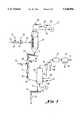
- FIG. 1is a schematic diagram of an integrated coal gasification gas turbine power plant using the hot gas cleanup system of the current invention.
- FIG. 2is a schematic diagram of the hot gas cleanup system shown in FIG. 1.
- FIG. 3is a more detailed schematic of the primary filter and oxidizer portion of the system shown in FIG. 2.
- FIG. 4is a more detailed schematic of the sulfur polishing unit, secondary filter and sorbent regenerator portion of the system shown in FIG. 2.
- FIG. 5is a cross-section through the primary filter shown in FIG. 2.
- FIG. 6is a detailed view of a candle array of the primary filter shown in FIG. 5.
- FIG. 7is a detailed view of one of the candles in the candle array shown in FIG. 6.
- FIG. 8is partial cross-section of the alkali removal vessel shown in FIG. 2.
- FIG. 9is partial cross-section of the sulfur polishing vessel shown in FIG. 2.
- FIG. 10is partial cross-section of the sorbent regenerator vessel shown in FIG. 2.
- FIG. 11is partial cross-section of the oxidizer vessel shown in FIG. 2.
- FIG. 1a schematic diagram of an integrated coal gasification gas turbine power plant.
- the plantcomprises a compressor 1 that inducts ambient air 9 and produces high pressure air 10 that is used to gasify coal 11 in a gasifier 2.
- the gasifierproduces a fuel gas 12 that may have a temperature and pressure as high as 1650° C. (3000° F.) and 2760 kPa(400 psia), respectively, and that is laden with particulates, chiefly coal slag and ash, as well as sulfur species, chiefly hydrogen sulfide and COS, and alkali species.
- the fuel gas 12is passed through a cyclone separator 3 in which a portion of the particulate matter is removed.
- the fuel gasthen flows through a heat exchanger 4 supplied with feedwater or steam 13 and in which the temperature of the fuel gas is reduced to approximately 925° C. (1700° F.)
- the fuel gas 20 from the heat exchanger 4is then processed in the gas cleanup system 5 according to the current invention.
- the clean gas 15is combusted in a combustor 6, into which a supplemental fuel--such as oil or natural gas--may be added and the hot gas expanded in a turbine 7.
- the expanded gas 18 from the turbine 7flows through a heat recovery steam generator 8, supplied with heated feedwater or steam from the heat exchanger 4, and the gas 19 is then exhausted to atmosphere.
- the gas cleanup systemis shown in an overall fashion in FIG. 2.
- the systemhas three major subsystems--a primary sulfur removal and oxidizer subsystem 21, a polishing sulfur removal and regenerator system 22, and an alkali removal unit 23.
- a primary sulfur sorbent 24is injected into the fuel gas 20 upstream of a primary filter 25, thereby removing a substantial portion of the sulfur from the fuel gas.
- the sorbent laden fuel gas 44then flows through the primary filter 25, wherein a substantial portion 73 of the used and unused primary sorbent is removed and directed to an oxidizer 26.
- the filtered fuel gas 40is then directed to the alkali removal unit 23, containing a fixed alkali sorbent bed, wherein a substantial portion of the alkali species is removed from the fuel gas.
- the fuel gas 41is directed to a polishing de-sulfurizer 33, in which a polishing sulfur sorbent in maintained in a bed fluidized by the fuel gas 41.
- the polishing de-sulfurizer 33removes a substantial portion of the sulfur remaining in the fuel gas and discharges the fuel gas 42 to a cyclone separator for particulate removal.
- the fuel gas 43then flows through a secondary filter 35 and the clean gas is discharged from the system.
- the solids 97 captured by the filter, which includes used and unused sorbent,are then removed for reprocessing, which may include regeneration, as discussed further below.
- the used polishing sorbent 87 from the polishing de-sulfurizer 33is directed to a regenerator 34 into which air 29 is drawn to fluidize a bed of the used sorbent, thereby producing regenerated polishing sorbent 92 that is recycled to the polishing de-sulfurizer 33.
- the regenerationalso produces sulfur dioxide, which is directed, via a cyclone separator 28, to the oxidizer 26.
- the used and unused primary sorbent 73is maintained in a bed fluidized by the sulfur dioxide rich gas stream 93 from the regenerator 34 and by air 78. This results in the used primary sorbent being converted to a more stable compound for waste disposal 31.
- the gas 36 from the oxidizer 26is discharged to a stack (not shown). The various components of the system and the reactions that occur in these components are discussed in more detail below.
- the primary sulfur sorbent 24is injected as relatively fine particles directly into the fuel gas 20 upstream of the primary filter 25 by means of an injector 60.
- the sorbent 24is calcium based, such as calcitic limestone or dolomitic limestone, that removes sulfur by forming a sulfur compound--i.e, CaS--referred to as "used" sorbent. Accordingly, the significant reaction is:
- the rate at which the sorbent 24 is injectedis sufficient to maintain the calcium/sulfur feed ratio at approximately 2.0, by atomic ratio.
- excess, unused calcium based sorbent removed by the primary filter 25is used to capture sulfur dioxide gas, produced by the regeneration of a copper based sorbent in the polishing de-sulfurizer 33, by fluidizing this excess sorbent in the oxidizer 6.
- the size of the sorbent 24 particlesshould be sufficiently small to be readily fluidizable.
- calcitic limestone sorbent particles of -70 meshi.e., less than about 250 ⁇ m in diameter
- these particleshave a mass-mean diameter of about 50 ⁇ m and a surface-mean diameter of about 20 ⁇ m. Use of such small diameter particles, made possible by the high performance of the primary filter, as discussed further below, improves the efficiency of the de-sulfurization process.
- particles of an alkali sorbent 62are also injected, via an injector 61, directly into the fuel gas 20 upstream of the primary filter 25.
- the alkali sorbent 62is emathlite sorbent that has been pulverized to 80% -325 mesh size.
- the alkali removal unit 23comprises a vessel 170 enclosing a packed bed 210 of emathlite pellets 214 supported on a distribution plate 174, as shown in FIG. 8.
- the distribution plate 174is formed from a ceramic material and has a quantity of holes 207 formed therein so as to create sufficient pressure drop to maintain a uniform gas flow through-the bed 210.
- the vessel 170includes a gas inlet 172, a gas outlet 173, and a solids inlet 171.
- the primary filter 25comprises a vessel 150 that is lined with refractory material 175 and in which multiple filter columns 176 are disposed.
- Each filter column 176is formed by three candle arrays 157 supported on a support structure 155, which includes a high alloy tube sheet and an expansion assembly.
- each candle array 157is comprised of multiple candles 159 connected to a common plenum 158.
- each candleis comprised of a hollow ceramic tube 160 having porous walls into which gas may flow, leaving particulate matter as a filter cake formed on the exterior surfaces of the tube 160.
- a pulse-type cleaning systemis incorporated into the primary filter 25. This cleaning is accomplished by connecting the output of a pulse compressor 65 to the candle plenums 158 by means of a pulse control valve 63, as shown in FIG. 3.
- the compressor 65directs pulses of a gas 66, such as nitrogen or fuel gas, into the hollow portions of the candles 160 to prevent excessive buildup of the filter cake on the exterior surfaces of the candles.
- the primary filter vessel 157has a gas inlet 153 into which the sorbent laden fuel gas 44 is directed.
- the fuel gas 44is directed by a liner 154 to flow upward within an annular passage formed between the vessel and the liner.
- the fuel gas 44then flows downward and into the candles 160 within each array 157.
- the cleaned fuel gas 40flows from the candle array plenums 158 into a common plenum 156 and then discharges through a gas outlet 151.
- a solids outlet 152 at the bottom of the vessel 150allows the particles removed from the fuel gas to be discharged from the vessel. These particles include unused and used primary sulfur sorbent--i.e., in the preferred embodiment, limestone (CaCO 3 ) and calcium sulfide (CaS).
- Candle-type ceramic barrier filters of the general type discussed aboveare disclosed in U.S. Pat. Nos. 4,973,458 (Newby et al.), 4,812,149 (Griffin et al.), 4,764,190 (Israelson et al.), 4,735,635 (Israelson et al.) and 4,539,025 (Ciliberti et al.), each of which is incorporated herein in its entirety by reference.
- the inventioncould also be practices using other types of high performance, high temperature filters, such as bag filter elements--see, for example, U.S. Pat. No. 4,553,986 (Ciliberti et al.), incorporated herein in its entirety by reference--or a cross-flow type filter.
- the solids 73i.e., CaCO 3 and CaS
- the solids 73 removed from the primary filter 25are transferred, via a screw conveyor 67, to a lock hopper 68 pressurized by a gas 70 and from which gas 69 is vented.
- the de-pressurized solids 74are collected in a hopper 71 and then directed, via a rotary feed 72, to the oxidizer 26 for capture of sulfur dioxide produced during the regeneration of polishing sorbent, as discussed further below.
- the polishing desulfurizer 33comprises a vessel 180 enclosing a fluidized bed 211 of a sulfur sorbent 86 fluidized by the fuel gas 40. Under normal operating conditions, the bed is maintained at a temperature of approximately 870° C. (1600° F.) and a pressure of approximately 1585 kPa (230 psia).
- the vessel 180has an inlet 181 for receiving a mixture 46 of the fuel gas 40 and particles of polishing sorbent 92 that have been regenerated, as discussed below, a solids inlet 183 by which fresh polishing sorbent feed 86 is introduced, a gas outlet 47 for discharging the de-sulfurized gas 47, and a solids outlet 184 for discharging used polishing sorbent 87 to the regenerator 34.
- polishing sulfur sorbent 92As shown in FIG. 4, polishing sulfur sorbent 92, regenerated as discussed below, is transported vertically upward by the fuel gas 40 stream into the vessel 180, creating a "jetting" fluidized bed 211. This allows the desulfurization reactions to begin during initial entrainment of the polishing sorbent 92 and provides intensive mixing of the sorbent 92 particles within the "jet” that prevents the highly exothermic reactions from creating excessive temperatures in the sorbent. Fresh polishing sorbent 86 is added to the vessel 180 as necessary to make up for sorbent losses.
- the fuel gas 47 discharged from the vessel 180passes through a pair of cyclone separators 27' and 27" in which entrained sorbent particles are captured and returned to the vessel via an L-valve 50 into which a pressurized gas 59, such as nitrogen or fuel gas, is introduced.
- a pressurized gas 59such as nitrogen or fuel gas
- the polishing sulfur sorbent 86is a copper based sorbent.
- the sorbentis copper oxide, 10% weight copper, supported as a coating on porous alumina particles that have been crushed to a -35 mesh size (i.e., less that 500 ⁇ m).
- the particle sizeis selected to ensure good fluidization in the bed 211.
- a mixture of copper oxide particles and inert silica or alumina particlesmay be used. The major reactions are the reduction of copper oxide to copper metal and the sulfidation of the copper so as to produce a sulfur compound:
- the fuel gas 43is directed to the secondary filter 35 in which particulates are removed.
- the secondary filter 35is of the ceramic barrier type and may of identical design to the primary filter 25.
- the solids 97 removed from the filterare transferred, via a screw conveyor 98, to lock hopper 101 pressurized by a gas 100 and from which gas 99 is vented.
- the particles removed by secondary filterare essentially unused polishing sulfur sorbent 86 (i.e., copper oxide) and used sorbent (i.e., copper sulfide) that is free from contamination by coal ash and calcium based sorbent. Consequently, from the lock hopper 101, the solids are collected in hopper 102 and then removed for reprocessing--for example, in the regenerator 34.
- a standlegremoves used polishing sulfur sorbent 87 particles (i.e., copper sulfide) from the polishing de-sulfurizer 33 and directs them, via an N-valve 88, into the regenerator 34.
- Pressurized air 29is also introduced into the regenerator 34, along with particles 89 captured by cyclones 28' and 28" and introduced via an L-valve 50 supplied with pressurized air 90.
- the major reactions in the regenerator 34are the conversion of the copper sulfide into copper and sulfur dioxide, and the oxidation of copper into fresh copper oxide sorbent:
- the regenerator 34is comprised of a refractory lined vessel 190 that encloses a slugging fluidized bed of used and unused sorbent particles fluidized by the pressurize air 29 and supported on a distribution plate 206. Under normal operating conditions, the bed is maintained at a temperature of approximately 870° C. (1600° F.) and pressure of approximately 1650 kPa (240 psia).
- the vessel 190has an air inlet 191 for receiving the pressurized air 91, a solids inlet 193 for receiving the used sorbent 87 to be regenerated, a solids inlet 192 through which the particles 89 captured by the cyclones 28 and 28" are returned, a gas outlet 195 for discharging the sulfur dioxide 91 produced by the regeneration, and a solids outlet 194 for returning regenerated sorbent 92 to the polishing desulfurizer 33.
- the oxidizereliminates the need for an expensive process for converting the SO 2 rich gas from the regenerator into elemental sulfur or sulfuric acid by reacting it with the unused primary sulfur sorbent.
- the solids 31i.e., calcium sulfate
- the gas 85 discharged from the oxidizer 26passes through two cyclone separators 81' and 81", a heat exchanger 83 in which the gas is cooled to 315° C. (600° F.) and a conventional bag house filter 84.
- the gas 36is then discharged to atmosphere through a stack.
- the solids 82 removed by the bag house filter 84are cooled and stored for disposal, along with the solids 80 removed by the second cyclone 81".
- the solids 79 removed by the first cyclone 81'are returned to the oxidizer 26 via an L-valve 50 supplied with air 77.
- the oxidizer 26is essentially a two stage, circulating combustor in which both stages are operated at super-stoichiometric conditions. As shown in FIG. 11, the oxidizer 26 is comprised of a vessel 200 that encloses an atmospheric fluidized bed 213 of used and unused primary sorbent particles--i.e., primarily--70 mesh limestone that has been partially sulfided.
- the sulfur dioxide rich stream 93 from the regenerator 34enters an inlet plenum via inlet 204 and is distributed by a bubble cap distribution plate 206 --that is, the gas stream 93 is introduced below the distribution plate. This gas stream serves to fluidize the primary bed 202.
- the air 78is injected above the distribution plate 206 by means of an inlet 203, fluidizing a second stage dilute bed 215. Under normal operating conditions, the bed is maintained at a temperature of approximately 870° C. (1600° F).
- the vessel 200has a first solids inlet 201 for receiving the primary sorbent 74 from the primary filter, and a second solids inlet (not shown) through which the particles 79 captured by the cyclone separator 81' are returned.
- the current inventionhas been illustrated with reference to fuel gas produced by a gasifier, the invention is equally applicable for cleaning the fuel gas produced in a direct coal-fired turbine.
- the inventionhas been disclosed as having both a primary and a polishing sulfur removal stage, the invention could also be practiced with only a single stage of sulfur removal, using only either the primary or polishing sorbent. Accordingly, the current invention may be embodied in other specific forms without departing from the spirit or essential attributes thereof and, accordingly, reference should be made to the appended claims, rather than to the foregoing specification, as indicating the scope of the invention.
Landscapes
- Chemical & Material Sciences (AREA)
- Engineering & Computer Science (AREA)
- Combustion & Propulsion (AREA)
- Chemical Kinetics & Catalysis (AREA)
- General Chemical & Material Sciences (AREA)
- Oil, Petroleum & Natural Gas (AREA)
- Organic Chemistry (AREA)
- Industrial Gases (AREA)
- Solid-Sorbent Or Filter-Aiding Compositions (AREA)
- Treating Waste Gases (AREA)
Abstract
Description
CaCO.sub.3 +H.sub.2 S=CaS+H.sub.2 O+CO.sub.2.
Ca(OH.sub.2)=CaO+H.sub.2 O
CaO+H.sub.2 S/CO.sub.2 =CaS/CaCO.sub.3.
CuO+H.sub.2 /CO=Cu+H.sub.2 O/CO.sub.2
2 CU+H.sub.2 S=Cu.sub.2 S+H.sub.2.
CU+1/2O.sub.2 =CuO
Cu.sub.2 S+O.sub.2 =2 Cu+SO.sub.2.
CaCO.sub.3 =CaO+CO.sub.2
CaO+SO.sub.2 +1/2O.sub.2 =CaSO.sub.4
CaS+2O.sub.2 =CaSO.sub.4
C+O.sub.2 =CO.sub.2.
Claims (10)
Priority Applications (8)
| Application Number | Priority Date | Filing Date | Title |
|---|---|---|---|
| US08/054,986US5540896A (en) | 1993-04-30 | 1993-04-30 | System and method for cleaning hot fuel gas |
| TW083103147ATW245652B (en) | 1993-04-30 | 1994-04-11 | |
| ES94302604TES2126709T3 (en) | 1993-04-30 | 1994-04-13 | SYSTEM AND PROCEDURE FOR DEPURATION OF HOT FUEL GAS. |
| EP94302604AEP0622442B1 (en) | 1993-04-30 | 1994-04-13 | System and method for cleaning hot fuel gas |
| DE69415579TDE69415579T2 (en) | 1993-04-30 | 1994-04-13 | Method and device for cleaning hot fuel gases |
| KR1019940009208AKR100278949B1 (en) | 1993-04-30 | 1994-04-29 | Systems and methods for removing sulfur species from hot gases from coal |
| CA002122523ACA2122523A1 (en) | 1993-04-30 | 1994-04-29 | System and method for cleaning hot fuel gas |
| JP11588894AJP3638969B2 (en) | 1993-04-30 | 1994-05-02 | Apparatus and method for removing sulfur species from hot gases obtained from coal |
Applications Claiming Priority (1)
| Application Number | Priority Date | Filing Date | Title |
|---|---|---|---|
| US08/054,986US5540896A (en) | 1993-04-30 | 1993-04-30 | System and method for cleaning hot fuel gas |
Publications (1)
| Publication Number | Publication Date |
|---|---|
| US5540896Atrue US5540896A (en) | 1996-07-30 |
Family
ID=21994826
Family Applications (1)
| Application Number | Title | Priority Date | Filing Date |
|---|---|---|---|
| US08/054,986Expired - LifetimeUS5540896A (en) | 1993-04-30 | 1993-04-30 | System and method for cleaning hot fuel gas |
Country Status (8)
| Country | Link |
|---|---|
| US (1) | US5540896A (en) |
| EP (1) | EP0622442B1 (en) |
| JP (1) | JP3638969B2 (en) |
| KR (1) | KR100278949B1 (en) |
| CA (1) | CA2122523A1 (en) |
| DE (1) | DE69415579T2 (en) |
| ES (1) | ES2126709T3 (en) |
| TW (1) | TW245652B (en) |
Cited By (12)
| Publication number | Priority date | Publication date | Assignee | Title |
|---|---|---|---|---|
| US5753198A (en)* | 1996-12-30 | 1998-05-19 | General Electric Company | Hot coal gas desulfurization |
| US5854173A (en)* | 1996-05-31 | 1998-12-29 | Electric Power Research Institute, Inc. | Flake shaped sorbent particle for removing vapor phase contaminants from a gas stream and method for manufacturing same |
| US5955039A (en)* | 1996-12-19 | 1999-09-21 | Siemens Westinghouse Power Corporation | Coal gasification and hydrogen production system and method |
| US5964085A (en)* | 1998-06-08 | 1999-10-12 | Siemens Westinghouse Power Corporation | System and method for generating a gaseous fuel from a solid fuel for use in a gas turbine based power plant |
| US5988080A (en)* | 1995-10-03 | 1999-11-23 | Ebara Corporation | Waste heat recovery system and power generation system with dust filtration |
| US6077490A (en)* | 1999-03-18 | 2000-06-20 | Mcdermott Technology, Inc. | Method and apparatus for filtering hot syngas |
| WO2002002208A1 (en)* | 2000-06-29 | 2002-01-10 | Mcdermott Technology, Inc. | Regenerable gas desulfurizer |
| US20040247509A1 (en)* | 2003-06-06 | 2004-12-09 | Siemens Westinghouse Power Corporation | Gas cleaning system and method |
| USRE39098E1 (en) | 1998-05-30 | 2006-05-23 | Kansas State University Research Foundation | Porous pellet adsorbents fabricated from nanocrystals |
| CN101462022B (en)* | 2009-01-12 | 2011-06-29 | 宁波怡诺能源科技有限公司 | Circulating fluid bed flue-gas desulfurizing device |
| US20110209478A1 (en)* | 2009-03-11 | 2011-09-01 | Minoru Morita | Method of power generation by waste combustion and waste combustion system |
| US20130089482A1 (en)* | 2011-10-11 | 2013-04-11 | Phillips 66 Company | Water recovery and acid gas capture from flue gas |
Families Citing this family (5)
| Publication number | Priority date | Publication date | Assignee | Title |
|---|---|---|---|---|
| JP5344447B2 (en)* | 2007-10-17 | 2013-11-20 | 独立行政法人産業技術総合研究所 | Gasification system that reuses alkali evaporated in gasification furnace |
| EP2346802A4 (en)* | 2008-10-22 | 2012-11-21 | Southern Res Inst | PROCESS FOR DECONTAMINATING SYNTHESIS GAS |
| RU2425230C1 (en)* | 2010-04-12 | 2011-07-27 | Федеральное государственное бюджетное учреждение "Национальный исследовательский центр "Курчатовский институт" | Energy conversion method |
| CN107158876A (en)* | 2017-07-18 | 2017-09-15 | 洛阳建材建筑设计研究院有限公司 | The production of hydrocarbons technique of high-temperature oil gas dust arrester after a kind of oil shale retorting |
| CN112870753A (en)* | 2021-01-26 | 2021-06-01 | 广东申菱环境系统股份有限公司 | Condensing type oil gas recovery device |
Citations (15)
| Publication number | Priority date | Publication date | Assignee | Title |
|---|---|---|---|---|
| FR2368989A1 (en)* | 1976-11-01 | 1978-05-26 | Uss Eng & Consult | METHOD AND APPARATUS FOR DESULFURING A HOT REDUCING GAS |
| FR2432887A1 (en)* | 1978-08-08 | 1980-03-07 | Inst Francais Du Petrole | PROCESS FOR PURIFYING A GAS CONTAINING HYDROGEN SULFIDE |
| US4343631A (en)* | 1981-01-30 | 1982-08-10 | Westinghouse Electric Corp. | Hot gas particulate removal |
| GB2106532A (en)* | 1981-09-23 | 1983-04-13 | Westfael Elekt Werke | Process for the separation of chlorine fluorine and sulphur from fuel gas and flue or exhaust gas |
| US4539025A (en)* | 1984-09-26 | 1985-09-03 | Westinghouse Electric Corp. | Filtering system |
| US4553986A (en)* | 1984-11-13 | 1985-11-19 | Westinghouse Electric Corp. | Filtering system and method of using same |
| US4735638A (en)* | 1986-11-18 | 1988-04-05 | The United States Of America As Represented By The United States Department Of Energy | Filter unit for use at high temperatures |
| US4735635A (en)* | 1986-01-10 | 1988-04-05 | Westinghouse Electric Corp. | Apparatus and process for filtering high temperature gas streams |
| US4737176A (en)* | 1986-05-19 | 1988-04-12 | The United States Of America As Represented By The United States Department Of Energy | Hot gas cross flow filtering module |
| US4764190A (en)* | 1987-02-10 | 1988-08-16 | Westinghouse Electric Corp. | High temperature, high pressure gas filter system |
| US4812149A (en)* | 1987-12-03 | 1989-03-14 | Westinghouse Electric Corp. | Hot inert gas purging for filter blowback process |
| US4927430A (en)* | 1988-05-26 | 1990-05-22 | Albert Calderon | Method for producing and treating coal gases |
| US4973458A (en)* | 1989-05-09 | 1990-11-27 | Westinghouse Electric Corp. | Fluidized bed system for removing particulate contaminants from a gaseous stream |
| US5143530A (en)* | 1990-10-22 | 1992-09-01 | Westinghouse Electric Corp. | Filtering apparatus |
| US5176088A (en)* | 1992-01-10 | 1993-01-05 | The Babcock & Wilcox Company | Furnace ammonia and limestone injection with dry scrubbing for improved simultaneous SOX and NOX removal |
- 1993
- 1993-04-30USUS08/054,986patent/US5540896A/ennot_activeExpired - Lifetime
- 1994
- 1994-04-11TWTW083103147Apatent/TW245652B/zhactive
- 1994-04-13DEDE69415579Tpatent/DE69415579T2/ennot_activeExpired - Lifetime
- 1994-04-13EPEP94302604Apatent/EP0622442B1/ennot_activeExpired - Lifetime
- 1994-04-13ESES94302604Tpatent/ES2126709T3/ennot_activeExpired - Lifetime
- 1994-04-29CACA002122523Apatent/CA2122523A1/ennot_activeAbandoned
- 1994-04-29KRKR1019940009208Apatent/KR100278949B1/ennot_activeExpired - Lifetime
- 1994-05-02JPJP11588894Apatent/JP3638969B2/ennot_activeExpired - Lifetime
Patent Citations (16)
| Publication number | Priority date | Publication date | Assignee | Title |
|---|---|---|---|---|
| FR2368989A1 (en)* | 1976-11-01 | 1978-05-26 | Uss Eng & Consult | METHOD AND APPARATUS FOR DESULFURING A HOT REDUCING GAS |
| FR2432887A1 (en)* | 1978-08-08 | 1980-03-07 | Inst Francais Du Petrole | PROCESS FOR PURIFYING A GAS CONTAINING HYDROGEN SULFIDE |
| US4251495A (en)* | 1978-08-08 | 1981-02-17 | Institut Francais Du Petrole | Process for purifying a hydrogen sulfide containing gas |
| US4343631A (en)* | 1981-01-30 | 1982-08-10 | Westinghouse Electric Corp. | Hot gas particulate removal |
| GB2106532A (en)* | 1981-09-23 | 1983-04-13 | Westfael Elekt Werke | Process for the separation of chlorine fluorine and sulphur from fuel gas and flue or exhaust gas |
| US4539025A (en)* | 1984-09-26 | 1985-09-03 | Westinghouse Electric Corp. | Filtering system |
| US4553986A (en)* | 1984-11-13 | 1985-11-19 | Westinghouse Electric Corp. | Filtering system and method of using same |
| US4735635A (en)* | 1986-01-10 | 1988-04-05 | Westinghouse Electric Corp. | Apparatus and process for filtering high temperature gas streams |
| US4737176A (en)* | 1986-05-19 | 1988-04-12 | The United States Of America As Represented By The United States Department Of Energy | Hot gas cross flow filtering module |
| US4735638A (en)* | 1986-11-18 | 1988-04-05 | The United States Of America As Represented By The United States Department Of Energy | Filter unit for use at high temperatures |
| US4764190A (en)* | 1987-02-10 | 1988-08-16 | Westinghouse Electric Corp. | High temperature, high pressure gas filter system |
| US4812149A (en)* | 1987-12-03 | 1989-03-14 | Westinghouse Electric Corp. | Hot inert gas purging for filter blowback process |
| US4927430A (en)* | 1988-05-26 | 1990-05-22 | Albert Calderon | Method for producing and treating coal gases |
| US4973458A (en)* | 1989-05-09 | 1990-11-27 | Westinghouse Electric Corp. | Fluidized bed system for removing particulate contaminants from a gaseous stream |
| US5143530A (en)* | 1990-10-22 | 1992-09-01 | Westinghouse Electric Corp. | Filtering apparatus |
| US5176088A (en)* | 1992-01-10 | 1993-01-05 | The Babcock & Wilcox Company | Furnace ammonia and limestone injection with dry scrubbing for improved simultaneous SOX and NOX removal |
Non-Patent Citations (11)
| Title |
|---|
| ASME Paper, Oct. 18, 1992, Development of a Direct Coal Fired Advanced Combined Cycle Concept for Repowering and New Base Load Generation, (Jensen et al.).* |
| ASME Paper, Oct. 18, 1992, Development of a Direct Coal-Fired Advanced Combined Cycle Concept for Repowering and New Base Load Generation, (Jensen et al.). |
| Development of Hot Gas Cleaning Systems for Advanced, Coal Based Gas Turbine Cycles, (Lippert et al.), Jul. 1993, Journal of Engineering for Gas Turbines & Power, pp. 658 664.* |
| Development of Hot Gas Cleaning Systems for Advanced, Coal-Based Gas Turbine Cycles, (Lippert et al.), Jul. 1993, Journal of Engineering for Gas Turbines & Power, pp. 658-664. |
| M. G. Klett, et al., Conceptual Designs of Advanced High Temperature Desulfurization Processes, vol. II, Dec. 1986 (NTIS No. DOE/MC/21098 2248 vol. 2).* |
| M. G. Klett, et al., Conceptual Designs of Advanced High-Temperature Desulfurization Processes, vol. II, Dec. 1986 (NTIS No. DOE/MC/21098-2248-vol. 2). |
| Proceedings of the Eleventh Annual Gasification and Gas Stream Cleanup Systems Contractors Review Meeting, Aug. 1991 NTIS No. DOE/METC 91/6123, vol. 1 and vol. 2).* |
| Proceedings of the Eleventh Annual Gasification and Gas Stream Cleanup Systems Contractors Review Meeting, Aug. 1991 NTIS No. DOE/METC-91/6123, vol. 1 and vol. 2). |
| S. Soung, et al., KRW High Temperature Coal Gas Desulfurization, Presented at the First Int. Conf. on Separation Science and Technology, Apr. 1986.* |
| Southern Company Services, Inc., Assessment of Coal Gasification/Hot Gas Cleanup Based Advanced Gas Turbine Systems, Final Report, Dec. 1990 (NTIS No. DOE/MC/26019 3004).* |
| Southern Company Services, Inc., Assessment of Coal Gasification/Hot Gas Cleanup Based Advanced Gas Turbine Systems, Final Report, Dec. 1990 (NTIS No. DOE/MC/26019-3004). |
Cited By (21)
| Publication number | Priority date | Publication date | Assignee | Title |
|---|---|---|---|---|
| US6298666B1 (en) | 1995-10-03 | 2001-10-09 | Ebara Corporation | Heat recovery system and power generation system |
| US5988080A (en)* | 1995-10-03 | 1999-11-23 | Ebara Corporation | Waste heat recovery system and power generation system with dust filtration |
| US6321540B1 (en) | 1995-10-03 | 2001-11-27 | Ebara Corp | Heat recovery system and power generation system |
| US6318088B1 (en) | 1995-10-03 | 2001-11-20 | Ebara Corporation | Heat recovery system and power generation system |
| US6116169A (en)* | 1995-10-03 | 2000-09-12 | Ebara Corporation | Heat recovery system and power generation system for wastes |
| US6301896B1 (en) | 1995-10-03 | 2001-10-16 | Ebara Corporation | Heat recovery system and power generation system |
| US5854173A (en)* | 1996-05-31 | 1998-12-29 | Electric Power Research Institute, Inc. | Flake shaped sorbent particle for removing vapor phase contaminants from a gas stream and method for manufacturing same |
| US5955039A (en)* | 1996-12-19 | 1999-09-21 | Siemens Westinghouse Power Corporation | Coal gasification and hydrogen production system and method |
| US5753198A (en)* | 1996-12-30 | 1998-05-19 | General Electric Company | Hot coal gas desulfurization |
| USRE39098E1 (en) | 1998-05-30 | 2006-05-23 | Kansas State University Research Foundation | Porous pellet adsorbents fabricated from nanocrystals |
| EP0964050A3 (en)* | 1998-06-08 | 2000-09-13 | Siemens Westinghouse Power Corporation | System and method for generating a gaseous fuel from a solid fuel for use in a gas turbine based power plant |
| EP0964050A2 (en) | 1998-06-08 | 1999-12-15 | Siemens Westinghouse Power Corporation | System and method for generating a gaseous fuel from a solid fuel for use in a gas turbine based power plant |
| US5964085A (en)* | 1998-06-08 | 1999-10-12 | Siemens Westinghouse Power Corporation | System and method for generating a gaseous fuel from a solid fuel for use in a gas turbine based power plant |
| US6077490A (en)* | 1999-03-18 | 2000-06-20 | Mcdermott Technology, Inc. | Method and apparatus for filtering hot syngas |
| WO2002002208A1 (en)* | 2000-06-29 | 2002-01-10 | Mcdermott Technology, Inc. | Regenerable gas desulfurizer |
| US20040247509A1 (en)* | 2003-06-06 | 2004-12-09 | Siemens Westinghouse Power Corporation | Gas cleaning system and method |
| US7056487B2 (en) | 2003-06-06 | 2006-06-06 | Siemens Power Generation, Inc. | Gas cleaning system and method |
| CN101462022B (en)* | 2009-01-12 | 2011-06-29 | 宁波怡诺能源科技有限公司 | Circulating fluid bed flue-gas desulfurizing device |
| US20110209478A1 (en)* | 2009-03-11 | 2011-09-01 | Minoru Morita | Method of power generation by waste combustion and waste combustion system |
| US8893498B2 (en)* | 2009-03-11 | 2014-11-25 | Tsukishima Kankyo Engineering Ltd. | Method of power generation by waste combustion and waste combustion system |
| US20130089482A1 (en)* | 2011-10-11 | 2013-04-11 | Phillips 66 Company | Water recovery and acid gas capture from flue gas |
Also Published As
| Publication number | Publication date |
|---|---|
| JPH0741777A (en) | 1995-02-10 |
| KR100278949B1 (en) | 2001-01-15 |
| DE69415579T2 (en) | 1999-05-27 |
| EP0622442A2 (en) | 1994-11-02 |
| ES2126709T3 (en) | 1999-04-01 |
| EP0622442A3 (en) | 1995-02-15 |
| DE69415579D1 (en) | 1999-02-11 |
| TW245652B (en) | 1995-04-21 |
| CA2122523A1 (en) | 1994-10-31 |
| JP3638969B2 (en) | 2005-04-13 |
| EP0622442B1 (en) | 1998-12-30 |
Similar Documents
| Publication | Publication Date | Title |
|---|---|---|
| US5540896A (en) | System and method for cleaning hot fuel gas | |
| US5243922A (en) | Advanced staged combustion system for power generation from coal | |
| RU2433341C1 (en) | Method to burn carbon-containing fuel using hard oxygen carrier | |
| US5069685A (en) | Two-stage coal gasification and desulfurization apparatus | |
| US4833877A (en) | Process for the reduction of pollutant emissions from power stations with combined gas/steam turbine processes with preceding coal gasification | |
| EP0550905A1 (en) | Method for reducing emissions when burning nitrogen containing fuels | |
| US10443005B2 (en) | All-steam gasification with carbon capture | |
| CN101351530A (en) | Petroleum hydrocarbon conversion unit with integrated combustion unit including carbon dioxide capture | |
| US20200148963A1 (en) | All-Steam Gasification for Supercritical CO2 Cycle System | |
| EP0634470A1 (en) | Transport gasifier | |
| US5597541A (en) | Apparatus for cleaning and cooling synthesized gas | |
| CA2718075C (en) | Process for using a facility for combusting carbonaceous materials and relating facility | |
| US5538703A (en) | Hot gas desulfurization by injection of regenerable sorbents in gasifier-exit ducts | |
| CZ259396A3 (en) | Method of cooling and purification of flue gases and apparatus for making the same | |
| US6079212A (en) | Gasification power generation process and gasification power generation equipment | |
| EP0294024B1 (en) | Process for removing nitrous oxides from a gas | |
| EP0634471A1 (en) | Coal gasification and sulfur removal process | |
| JP2002275479A (en) | Method and apparatus for producing combustible gas | |
| Ishikawa et al. | Development of a simultaneous sulfur and dust removal process for IGCC power generation system | |
| EP0531620B1 (en) | Separation of pollutants from flue gas of fossil fuel combustion and gasification | |
| JP2003171673A (en) | Gas generator | |
| JP2018058002A (en) | Gas treatment apparatus and gas treatment method | |
| JP3776603B2 (en) | Oxidation furnace for coal gasification combined cycle system | |
| CA2068911A1 (en) | Separation of pollutants in the incineration of municipal solid waste | |
| AU2006303828B2 (en) | System and method for calcination/carbonation cycle processing |
Legal Events
| Date | Code | Title | Description |
|---|---|---|---|
| AS | Assignment | Owner name:WESTINGHOUSE ELECTRIC CORPORATION, PENNSYLVANIA Free format text:ASSIGNMENT OF ASSIGNORS INTEREST;ASSIGNOR:NEWBY, RICHARD A.;REEL/FRAME:006552/0935 Effective date:19930419 | |
| STPP | Information on status: patent application and granting procedure in general | Free format text:APPLICATION UNDERGOING PREEXAM PROCESSING | |
| FEPP | Fee payment procedure | Free format text:PAYOR NUMBER ASSIGNED (ORIGINAL EVENT CODE: ASPN); ENTITY STATUS OF PATENT OWNER: LARGE ENTITY | |
| AS | Assignment | Owner name:SIEMENS WESTINGHOUSE POWER CORPORATION, FLORIDA Free format text:ASSIGNMENT NUNC PRO TUNC EFFECTIVE AUGUST 19, 1998;ASSIGNOR:CBS CORPORATION, FORMERLY KNOWN AS WESTINGHOUSE ELECTRIC CORPORATION;REEL/FRAME:009605/0650 Effective date:19980929 | |
| FPAY | Fee payment | Year of fee payment:4 | |
| FPAY | Fee payment | Year of fee payment:8 | |
| AS | Assignment | Owner name:SIEMENS POWER GENERATION, INC., FLORIDA Free format text:CHANGE OF NAME;ASSIGNOR:SIEMENS WESTINGHOUSE POWER CORPORATION;REEL/FRAME:016996/0491 Effective date:20050801 | |
| FPAY | Fee payment | Year of fee payment:12 | |
| AS | Assignment | Owner name:SIEMENS ENERGY, INC., FLORIDA Free format text:CHANGE OF NAME;ASSIGNOR:SIEMENS POWER GENERATION, INC.;REEL/FRAME:022482/0740 Effective date:20081001 Owner name:SIEMENS ENERGY, INC.,FLORIDA Free format text:CHANGE OF NAME;ASSIGNOR:SIEMENS POWER GENERATION, INC.;REEL/FRAME:022482/0740 Effective date:20081001 |