US5540689A - Apparatus for securing a rod adjacent to a bone - Google Patents
Apparatus for securing a rod adjacent to a boneDownload PDFInfo
- Publication number
- US5540689A US5540689AUS08/215,182US21518294AUS5540689AUS 5540689 AUS5540689 AUS 5540689AUS 21518294 AUS21518294 AUS 21518294AUS 5540689 AUS5540689 AUS 5540689A
- Authority
- US
- United States
- Prior art keywords
- rod
- spine
- bone
- pincer
- shape
- Prior art date
- Legal status (The legal status is an assumption and is not a legal conclusion. Google has not performed a legal analysis and makes no representation as to the accuracy of the status listed.)
- Expired - Lifetime
Links
- 210000000988bone and boneAnatomy0.000titleclaimsabstractdescription71
- 229910001000nickel titaniumInorganic materials0.000claimsabstractdescription15
- HLXZNVUGXRDIFK-UHFFFAOYSA-Nnickel titaniumChemical compound[Ti].[Ti].[Ti].[Ti].[Ti].[Ti].[Ti].[Ti].[Ti].[Ti].[Ti].[Ni].[Ni].[Ni].[Ni].[Ni].[Ni].[Ni].[Ni].[Ni].[Ni].[Ni].[Ni].[Ni].[Ni]HLXZNVUGXRDIFK-UHFFFAOYSA-N0.000claimsabstractdescription15
- 229910001285shape-memory alloyInorganic materials0.000claimsabstractdescription7
- 210000000080chela (arthropods)Anatomy0.000claimsdescription24
- 210000000078clawAnatomy0.000claimsdescription23
- 230000033001locomotionEffects0.000claimsdescription5
- 239000012781shape memory materialSubstances0.000claimsdescription4
- 238000000034methodMethods0.000abstractdescription32
- 238000001356surgical procedureMethods0.000abstractdescription14
- 206010039722scoliosisDiseases0.000abstractdescription10
- 230000007704transitionEffects0.000abstractdescription8
- 238000011084recoveryMethods0.000abstractdescription6
- 230000000694effectsEffects0.000abstractdescription4
- 239000007943implantSubstances0.000abstractdescription3
- 238000012937correctionMethods0.000description46
- 230000008569processEffects0.000description8
- 229910045601alloyInorganic materials0.000description7
- 239000000956alloySubstances0.000description7
- 229910000734martensiteInorganic materials0.000description5
- 229910052751metalInorganic materials0.000description5
- 239000002184metalSubstances0.000description5
- PXHVJJICTQNCMI-UHFFFAOYSA-NNickelChemical compound[Ni]PXHVJJICTQNCMI-UHFFFAOYSA-N0.000description4
- 238000010438heat treatmentMethods0.000description4
- 230000001045lordotic effectEffects0.000description3
- 230000001537neural effectEffects0.000description3
- 230000009466transformationEffects0.000description3
- 206010023509KyphosisDiseases0.000description2
- 208000007623LordosisDiseases0.000description2
- RTAQQCXQSZGOHL-UHFFFAOYSA-NTitaniumChemical compound[Ti]RTAQQCXQSZGOHL-UHFFFAOYSA-N0.000description2
- 230000008859changeEffects0.000description2
- 230000006835compressionEffects0.000description2
- 238000007906compressionMethods0.000description2
- 239000013078crystalSubstances0.000description2
- 230000003247decreasing effectEffects0.000description2
- 230000006870functionEffects0.000description2
- 239000000463materialSubstances0.000description2
- 238000012986modificationMethods0.000description2
- 230000004048modificationEffects0.000description2
- 229910052759nickelInorganic materials0.000description2
- 230000002980postoperative effectEffects0.000description2
- 210000000278spinal cordAnatomy0.000description2
- 210000000115thoracic cavityAnatomy0.000description2
- 239000010936titaniumSubstances0.000description2
- 229910052719titaniumInorganic materials0.000description2
- 206010058907Spinal deformityDiseases0.000description1
- 230000002159abnormal effectEffects0.000description1
- 230000005856abnormalityEffects0.000description1
- 229910001566austeniteInorganic materials0.000description1
- 230000036760body temperatureEffects0.000description1
- 230000001010compromised effectEffects0.000description1
- 238000010276constructionMethods0.000description1
- 230000001419dependent effectEffects0.000description1
- 230000004064dysfunctionEffects0.000description1
- 238000002594fluoroscopyMethods0.000description1
- 238000002513implantationMethods0.000description1
- 230000006872improvementEffects0.000description1
- 230000006698inductionEffects0.000description1
- 238000003780insertionMethods0.000description1
- 230000037431insertionEffects0.000description1
- 230000009545invasionEffects0.000description1
- 210000004705lumbosacral regionAnatomy0.000description1
- 230000005012migrationEffects0.000description1
- 238000013508migrationMethods0.000description1
- 210000000276neural tubeAnatomy0.000description1
- 210000001519tissueAnatomy0.000description1
- XLYOFNOQVPJJNP-UHFFFAOYSA-NwaterSubstancesOXLYOFNOQVPJJNP-UHFFFAOYSA-N0.000description1
- 210000002517zygapophyseal jointAnatomy0.000description1
Images

Classifications
- A—HUMAN NECESSITIES
- A61—MEDICAL OR VETERINARY SCIENCE; HYGIENE
- A61B—DIAGNOSIS; SURGERY; IDENTIFICATION
- A61B17/00—Surgical instruments, devices or methods
- A61B17/56—Surgical instruments or methods for treatment of bones or joints; Devices specially adapted therefor
- A61B17/58—Surgical instruments or methods for treatment of bones or joints; Devices specially adapted therefor for osteosynthesis, e.g. bone plates, screws or setting implements
- A61B17/68—Internal fixation devices, including fasteners and spinal fixators, even if a part thereof projects from the skin
- A61B17/70—Spinal positioners or stabilisers, e.g. stabilisers comprising fluid filler in an implant
- A61B17/7001—Screws or hooks combined with longitudinal elements which do not contact vertebrae
- A61B17/7032—Screws or hooks with U-shaped head or back through which longitudinal rods pass
- A—HUMAN NECESSITIES
- A61—MEDICAL OR VETERINARY SCIENCE; HYGIENE
- A61B—DIAGNOSIS; SURGERY; IDENTIFICATION
- A61B17/00—Surgical instruments, devices or methods
- A61B17/56—Surgical instruments or methods for treatment of bones or joints; Devices specially adapted therefor
- A61B17/58—Surgical instruments or methods for treatment of bones or joints; Devices specially adapted therefor for osteosynthesis, e.g. bone plates, screws or setting implements
- A61B17/68—Internal fixation devices, including fasteners and spinal fixators, even if a part thereof projects from the skin
- A61B17/70—Spinal positioners or stabilisers, e.g. stabilisers comprising fluid filler in an implant
- A61B17/7056—Hooks with specially-designed bone-contacting part
- A—HUMAN NECESSITIES
- A61—MEDICAL OR VETERINARY SCIENCE; HYGIENE
- A61B—DIAGNOSIS; SURGERY; IDENTIFICATION
- A61B17/00—Surgical instruments, devices or methods
- A61B17/56—Surgical instruments or methods for treatment of bones or joints; Devices specially adapted therefor
- A61B17/58—Surgical instruments or methods for treatment of bones or joints; Devices specially adapted therefor for osteosynthesis, e.g. bone plates, screws or setting implements
- A61B17/68—Internal fixation devices, including fasteners and spinal fixators, even if a part thereof projects from the skin
- A61B17/70—Spinal positioners or stabilisers, e.g. stabilisers comprising fluid filler in an implant
- A61B17/7001—Screws or hooks combined with longitudinal elements which do not contact vertebrae
- A61B17/7002—Longitudinal elements, e.g. rods
- A61B17/701—Longitudinal elements with a non-circular, e.g. rectangular, cross-section
- A—HUMAN NECESSITIES
- A61—MEDICAL OR VETERINARY SCIENCE; HYGIENE
- A61B—DIAGNOSIS; SURGERY; IDENTIFICATION
- A61B17/00—Surgical instruments, devices or methods
- A61B2017/00017—Electrical control of surgical instruments
- A61B2017/00212—Electrical control of surgical instruments using remote controls
- A—HUMAN NECESSITIES
- A61—MEDICAL OR VETERINARY SCIENCE; HYGIENE
- A61B—DIAGNOSIS; SURGERY; IDENTIFICATION
- A61B17/00—Surgical instruments, devices or methods
- A61B2017/00831—Material properties
- A61B2017/00867—Material properties shape memory effect
- A—HUMAN NECESSITIES
- A61—MEDICAL OR VETERINARY SCIENCE; HYGIENE
- A61F—FILTERS IMPLANTABLE INTO BLOOD VESSELS; PROSTHESES; DEVICES PROVIDING PATENCY TO, OR PREVENTING COLLAPSING OF, TUBULAR STRUCTURES OF THE BODY, e.g. STENTS; ORTHOPAEDIC, NURSING OR CONTRACEPTIVE DEVICES; FOMENTATION; TREATMENT OR PROTECTION OF EYES OR EARS; BANDAGES, DRESSINGS OR ABSORBENT PADS; FIRST-AID KITS
- A61F2/00—Filters implantable into blood vessels; Prostheses, i.e. artificial substitutes or replacements for parts of the body; Appliances for connecting them with the body; Devices providing patency to, or preventing collapsing of, tubular structures of the body, e.g. stents
- A61F2/02—Prostheses implantable into the body
- A61F2/30—Joints
- A61F2002/30001—Additional features of subject-matter classified in A61F2/28, A61F2/30 and subgroups thereof
- A61F2002/30003—Material related properties of the prosthesis or of a coating on the prosthesis
- A61F2002/3006—Properties of materials and coating materials
- A61F2002/30092—Properties of materials and coating materials using shape memory or superelastic materials, e.g. nitinol
- A—HUMAN NECESSITIES
- A61—MEDICAL OR VETERINARY SCIENCE; HYGIENE
- A61F—FILTERS IMPLANTABLE INTO BLOOD VESSELS; PROSTHESES; DEVICES PROVIDING PATENCY TO, OR PREVENTING COLLAPSING OF, TUBULAR STRUCTURES OF THE BODY, e.g. STENTS; ORTHOPAEDIC, NURSING OR CONTRACEPTIVE DEVICES; FOMENTATION; TREATMENT OR PROTECTION OF EYES OR EARS; BANDAGES, DRESSINGS OR ABSORBENT PADS; FIRST-AID KITS
- A61F2210/00—Particular material properties of prostheses classified in groups A61F2/00 - A61F2/26 or A61F2/82 or A61F9/00 or A61F11/00 or subgroups thereof
- A61F2210/0014—Particular material properties of prostheses classified in groups A61F2/00 - A61F2/26 or A61F2/82 or A61F9/00 or A61F11/00 or subgroups thereof using shape memory or superelastic materials, e.g. nitinol
- A61F2210/0023—Particular material properties of prostheses classified in groups A61F2/00 - A61F2/26 or A61F2/82 or A61F9/00 or A61F11/00 or subgroups thereof using shape memory or superelastic materials, e.g. nitinol operated at different temperatures whilst inside or touching the human body, heated or cooled by external energy source or cold supply
- A61F2210/0033—Particular material properties of prostheses classified in groups A61F2/00 - A61F2/26 or A61F2/82 or A61F9/00 or A61F11/00 or subgroups thereof using shape memory or superelastic materials, e.g. nitinol operated at different temperatures whilst inside or touching the human body, heated or cooled by external energy source or cold supply electrically, e.g. heated by resistor
- F—MECHANICAL ENGINEERING; LIGHTING; HEATING; WEAPONS; BLASTING
- F16—ENGINEERING ELEMENTS AND UNITS; GENERAL MEASURES FOR PRODUCING AND MAINTAINING EFFECTIVE FUNCTIONING OF MACHINES OR INSTALLATIONS; THERMAL INSULATION IN GENERAL
- F16B—DEVICES FOR FASTENING OR SECURING CONSTRUCTIONAL ELEMENTS OR MACHINE PARTS TOGETHER, e.g. NAILS, BOLTS, CIRCLIPS, CLAMPS, CLIPS OR WEDGES; JOINTS OR JOINTING
- F16B2200/00—Constructional details of connections not covered for in other groups of this subclass
- F16B2200/77—Use of a shape-memory material
- Y—GENERAL TAGGING OF NEW TECHNOLOGICAL DEVELOPMENTS; GENERAL TAGGING OF CROSS-SECTIONAL TECHNOLOGIES SPANNING OVER SEVERAL SECTIONS OF THE IPC; TECHNICAL SUBJECTS COVERED BY FORMER USPC CROSS-REFERENCE ART COLLECTIONS [XRACs] AND DIGESTS
- Y10—TECHNICAL SUBJECTS COVERED BY FORMER USPC
- Y10T—TECHNICAL SUBJECTS COVERED BY FORMER US CLASSIFICATION
- Y10T24/00—Buckles, buttons, clasps, etc.
- Y10T24/44—Clasp, clip, support-clamp, or required component thereof
- Y10T24/44641—Clasp, clip, support-clamp, or required component thereof having gripping member formed from, biased by, or mounted on resilient member
- Y10T24/4465—Integrally combined, independently operable, diverse clasps, clips, or support-clamps
- Y—GENERAL TAGGING OF NEW TECHNOLOGICAL DEVELOPMENTS; GENERAL TAGGING OF CROSS-SECTIONAL TECHNOLOGIES SPANNING OVER SEVERAL SECTIONS OF THE IPC; TECHNICAL SUBJECTS COVERED BY FORMER USPC CROSS-REFERENCE ART COLLECTIONS [XRACs] AND DIGESTS
- Y10—TECHNICAL SUBJECTS COVERED BY FORMER USPC
- Y10T—TECHNICAL SUBJECTS COVERED BY FORMER US CLASSIFICATION
- Y10T24/00—Buckles, buttons, clasps, etc.
- Y10T24/44—Clasp, clip, support-clamp, or required component thereof
- Y10T24/44983—Clasp, clip, support-clamp, or required component thereof formed from single rigid piece of material
- Y—GENERAL TAGGING OF NEW TECHNOLOGICAL DEVELOPMENTS; GENERAL TAGGING OF CROSS-SECTIONAL TECHNOLOGIES SPANNING OVER SEVERAL SECTIONS OF THE IPC; TECHNICAL SUBJECTS COVERED BY FORMER USPC CROSS-REFERENCE ART COLLECTIONS [XRACs] AND DIGESTS
- Y10—TECHNICAL SUBJECTS COVERED BY FORMER USPC
- Y10T—TECHNICAL SUBJECTS COVERED BY FORMER US CLASSIFICATION
- Y10T403/00—Joints and connections
- Y10T403/21—Utilizing thermal characteristic, e.g., expansion or contraction, etc.
Definitions
- the present inventionrelates to an improvement over prior methods and apparatus for surgically treating abnormal curvatures of the spine.
- the normal spinepossesses some degree of curvature in three different regions.
- the lumbar spineis normally lordotic (i.e., concave posteriorly), the thoracic spine kyphotic (i.e., convex posteriorly), and the cervical spine also lordotic. These curvatures are necessary for normal physiologic function, and correction is desirable when the spine has either too much or too little curvature in these regions as compared with the norm.
- the first successful internal fixation method for surgically treating scoliosisinvolves the use of the Harrington instrumentation system.
- a rigid rod having hooks at each endis implanted adjacent the concave side of the scoliotic spine.
- the hooksengage in the facet joints of a vertebra above and under the laminae of a vertebra below the abnormally curved region.
- the spineis manually straightened to a desired extent.
- the distraction rodis then used to maintain the correction by exerting vertical forces at each end on the two aforementioned vertebra.
- the rodcommonly has a ratcheted end over which the hooks are slidably mounted and locked in place. The effective length of the rod may thus be adjusted to an appropriate length for exerting the distractive force.
- the Harrington distraction rodbecause its corrective force is purely distractive, tends to correct curvature in both the frontal and sagittal planes. This means that unwanted loss of normal thoracic kyphosis or lumbar lordosis may inadvertently be produced. To compensate for this, a compression rod is sometimes placed on the convex side of the scoliotic spine.
- Another variation on the Harrington methodwhich addresses the same problem is to contour the distraction rod in the sagittal plane in accordance with the kyphotic and lordotic curvatures of the normal spine. This may, however, reduce the ability to apply large corrective forces in the frontal plane due to column buckling.
- the Harrington instrumentation systemhas been used successfully but exhibits some major problems. It requires a long post-operative period of external immobilization using a cast or brace. Also, because the distraction rod is fixed to the spine in only two places, failure at either of these two points means that the entire system fails. Failure at the bone-hook interface is usually secondary to mechanical failure of the bone due to excess distractive force.
- Segmental fixationmay be used with a Harrington distraction rod or, as is more usually the case, with a pair of so-called Luque or L-rods.
- L-rodshave a long segment which is aligned with the spine and a short segment perpendicular to the long segment. The short segments of the L-rods are inserted in notches or holes made in the spinous processes of vertebra above and below the deformed region of the spine. By placing the two L-rods on opposite sides of the spine and in opposite longitudinal orientation, the entire system is made less vulnerable to vertical migration.
- the corrective forcesare applied in a transverse direction via the sublaminar or spinous process wires rather than in a longitudinal direction as with a Harrington distraction rod. Since the corrective forces are applied transversely, the integrity of the system is not compromised when the rods are contoured to accommodate normal anatomic kyphosis and lordosis.
- the shape-memory alloy, nitinol,has also been attempted as a Harrington rod without segmental fixation to correct scoliosis. This was unsuccessful because the corrective forces could not be transmitted effectively from the rod to the spine.
- It iSa still further object of the present method to allow the easy technical insertion of an implant for correcting scoliosis by deforming the implant to match the shape of the patient's spine.
- the present inventionis a method and apparatus which uses a shape memory alloy, such as nitinol, to enhance the function of segmental spine instrumentation in the treatment of scoliotic spinal deformities.
- a correction rodwhich may be either circular or non-circular must be segmentally attached to the spine so as to impart transverse and torsional corrective forces to the spine.
- the rodmust be affixed to the spine, during some stages of correction it must be free to slide along the spine, while during others it must be rigidly coupled to the spine.
- Segmental affixation of the rod combined with rod mobility and alternate rod rigidityis accomplished utilizing bone holding devices, such as hooks, screws, or the like, fashioned from shape memory materials such as nitinol.
- Each bone holding devicecomprises a rod housing formed integrally with a bone hook which is originally sized to securely fit the vertebrae.
- each bone hook of the bone clampis cooled and expanded to a size larger than the individual vertebra.
- the bone hookis then placed about the vertebra and heated until its distal end encircles a portion of the vertebra to firmly secure the entire bone clamp to the vertebra. The above process is then repeated until the number of bone clamps necessary to affix the rod to the spine have been connected to the vertebrae.
- each of the rod housingsinclude a pincer.
- the distance between each claw of the pinceroriginally is greater than the diameter of a circular rod or the longest side of a non-circular rod. That shape of the rod housings improves over prior bone clamps because it allows the rod to be placed directly and simultaneously into each of the rod housings.
- each pinceris crimped such that their claws encircle the rod.
- the friction between the rod housings and the rodis insufficient to prevent the rod from sliding freely within the rod housings. That is, the inner surface of each the rod housings contact the correction rod; however, the frictional forces developed between the two surfaces are not sufficient to prevent rod movement.
- heatis applied to pincers of the rod housings, causing their claws to further encircle the rod such that the frictional forces therebetween are sufficient to prevent the rod from sliding within the rod housings.
- An alternative bone clampcomprises a bone hook having a pincer-type shape formed integrally with a rod housing.
- the bone clampwhich originally is sized to securely fit the vertebrae, is cooled and expanded to a size larger than the vertebra.
- the bone hookis then placed about the vertebra and heated until its pincers snugly encircle the vertebra, thereby, firmly attaching the entire bone clamp to the vertebra.
- the above processis then repeated until the number of bone clamps necessary to affix the rod to the spine are connected to the vertebrae.
- Another alternative bone clampcomprises two separate members which are coupled together during surgery to form the bone clamp.
- Each memberis identical and comprises a claw formed integrally with a rod housing wherein the inner face of the rod housing edge integrally formed with the claw is provided with a hole on one side and a connector rod having a hook at its end on the other.
- the two membersare first cooled in order to straighten the hook on the end of each member and expand the claws.
- the two membersare then placed in opposed relation about the vertebra. That is, the claws face each other and surround the vertebra while the connector rod of each member fits through the hole provided in the opposite member.
- the membersare heated which causes the hook at the end of the connector rods to reform, thereby, securing the two members together and preventing their uncoupling.
- the clawsencircle the vertebra to firmly connect the bone clamp. The above process is then repeated until the number of bone clamps necessary to affix the rod to the spine have been connected to the vertebrae.
- each of the rod housings of the alternative bone clampsmay be fitted with a blocker.
- the blockercomprises a tube constructed of a shape memory material such as nitinol which is circularly-shaped so that the edges of the tube overlap.
- the original shape of the blockersis such that their outer diameters are the same as the correction rod.
- the overlapping shape of the blockersis chosen because it permits their inner diameters to be significantly increased or decreased with only a small concurrent change in their outer diameters.
- each blockeris cooled to allow its inner diameter to be expanded and its outer diameter to shrink slightly which permits the blocker to form a cylinder sliding on the rod housing while the correction rod easily fits within each blocker.
- the inner diameters of the blockersare large enough to permit the rod to slide freely, those inner diameters are still small enough to provide a bearing-like fit and surface for the correction rod to the rod housings. That is, the inner surfaces of the blockers contact the correction rod; however, the frictional forces developed between the two surfaces are not sufficient to prevent correction rod movement.
- heatis applied to the blockers, causing them to return to their original shape, thereby completely clamping the correction rod firmly within the rod housing. After the blockers have returned to their original shape, the frictional forces between the inner surfaces of the blockers and the correction rod are sufficient to prevent the rod from sliding.
- the correction rodis first heated to a temperature at which the crystalline structure of nitinol is entirely in the parent phase.
- a transformation temperaturewhich is in a 10° C. range of normal body temperature is selected for rod construction.
- the rodis then contoured to the ideal shape to which it is desired to correct the patient's spine. After that is accomplished, the rod is cooled to the point where the martensite crystal structure replaces the austenitic phase structure.
- the rodmay now be further deformed but will "remember" the original ideal shape upon being heated to the shape transition temperature.
- the rodis deformed to a shape which accommodates the existing shape of the patient's scoliotic spine. During this deformation, the temperature of the rod must be maintained below the shape transition temperature. The rod is then segmentally fixed to spine as described above. Some amount of correction may be attained at surgery, but it should be less than the ideal shape to which the rod memory is set so that a potential for shape recovery work exists in the implanted rod. Thus, post-operatively, additional correction may be attained by heating the rod to the shape transition temperature. Because of the segmental fixation, and the fact that the shape recovery of the alloy is a local phenomena, shape recovery forces may be confined to certain vertebral levels as desired by only applying the heat to certain local areas of the rod.
- the extent of heating, and, thus, the amount of shape recovery forcemay be controlled so that the rod moves to its ideal shape to the degree that the spine can withstand without risking neural damage or failure of the metal-bone interface. Also, rotation of the spine due to scoliosis may be corrected by the torque exerted by the rod.
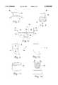
- FIG. 1is a side elevation view depicting the bone clamp of the present invention.
- FIG. 2is a front elevation view depicting the bone clamp of the present invention fitted with a circular rod in its untransformed state.
- FIG. 3is a front elevation view depicting the bone clamp of the present invention fitted with a circular rod in its transformed state.
- FIG. 4is a front elevation view depicting the bone clamp of the present invention fitted with a non-circular rod in its untransformed state.
- FIG. 5is a front elevation view depicting the bone clamp of the present invention fitted with a non-circular rod in its transformed state.
- FIG. 6is a side elevation view depicting the cooled state of an alternative embodiment of the bone clamp.
- FIG. 7is a side elevation view depicting the heated state of the alternative embodiment of the bone clamp.
- FIG. 8is a side elevation view depicting a second alternative embodiment of the bone clamp.
- FIG. 9is a side elevation view depicting the heated state of one member of the bone clamp of the second alternative embodiment.
- FIG. 10is a side elevation view depicting the cooled state of one member of the bone clamp of the second alternative embodiment.
- FIG. 11is a perspective view depicting the blocker utilized in both alternative embodiments of the bone clamps.
- FIG. 12is a end elevation view depicting the mounting of the correction rod within the rod housing of one of the alternative bone clamps.
- the implantable rod used to apply corrective forces to the spineis constructed of a shape-memory alloy such as nitinol.
- Nitinolis a nearly equal atomic ratio of nickel and titanium which exhibits a shape-memory effect. That is, after being deformed (up to about 8% strain) the material remembers its original annealed shape and will return to that original shape when heated above the shape transition temperature. In so doing, the alloy converts heat energy into mechanical work. The mechanical work done while the material is undergoing shape recovery can be much greater than that originally imparted during the initial plastic deformation.
- an alloyIn order for an alloy to exhibit the shape-memory effect, it must be a crystalline structure which can shift into the so-called parent phase when it is subjected to a certain temperature condition and then shift into the configuration known as martensite when the temperature is lowered.
- the alloyis first annealed to a specified shape. The alloy may then be heated to a temperature high enough that the crystalline structure assumes the parent phase or which is referred to in the art as the austenite configuration. Next, the alloy is cooled until it reverts to the martensite configuration. The alloy may now be further deformed randomly but will return to the original shape when heated to a temperature above that at which the martensite returns to the parent phase.
- the specific transitional temperature at which the phase transition occurscan be controlled by controlling the exact nickel to titanium ratio.
- shape-memory alloysfor use in the surgical correction of scoliosis has been investigated before, using a Harrington distraction rod constructed of nitinol, but the corrective forces could not be applied effectively to the spine.
- properties of a shape-memory alloyare utilized by a segmental fixation method for correcting scoliosis. These include rotatory correction in the transverse plane, less applied force at the bone-metal interface which increase the efficiency of transverse forces in correcting severely deformed spines in the frontal plane, localized correction applied post-operatively while the patient is monitored to minimize the risk of neural damage, the fact that the rod can be contoured to the pre-operative shape of the patient's spine. The corrective forces can be effectively applied to the spine.
- a single rod or a plurality of rods constructed of nitinolis first deformed while in the parent phase crystalline configuration to the ideal shape to which it is desired to eventually correct a particular patient's spine.
- the rodis then cooled until the martensite transformation occurs.
- the rodWhile maintaining the rod below the shape transition temperature, the rod may be deformed to conform to present shape of the patient's spine, which may include twisting. Alternatively, the rod may deviate somewhat from the spine's pre-operative shape in order to apply some correction during surgery. Because all of the corrective potential of the rod is stored as shape-memory, the rod can be positioned to lie immediately adjacent to the spine all along its length. This improves the rigidity of whatever technique of segmental fixation is used because the rod may rest firmly against the spine.
- the rod or rods which may be either circular or non-circularis segmentally fixed to the spine using the apparatus and method described herein in order to provide sufficient fixation rigidity and strength. Because, as explained below, the corrective forces are applied gradually in a manner which lessens the stresses borne by the individual fixation points, the present method employs bone clamps (described herein) rather than sublaminar wires to segmentally fix the rod to the spine. The present invention, therefore, by avoiding invasion of the neural canal, greatly reduces the risk of damage to the spinal cord. However, it is to be understood that techniques employing existing devices such as wires, hooks, tape, or screws could be used to secure the correction rod to the scoliotic spine.
- Bone holding device 50is constructed of nitinol and comprises rod housing 51 which includes pincer 54 and is formed integrally with bone hook 52 which is originally sized to securely fit about the vertebrae and oriented transverse to pincer 54 to facilitate the mounting of rod housing 51 adjacent to a vertebra.
- rod housing 51which includes pincer 54 and is formed integrally with bone hook 52 which is originally sized to securely fit about the vertebrae and oriented transverse to pincer 54 to facilitate the mounting of rod housing 51 adjacent to a vertebra.
- bone hook 52is cooled and expanded to a size larger than the individual vertebra.
- Claw 53 of bone hook 52is then placed about the vertebra and heated until its distal end encircles a portion of the vertebra to firmly secure bone holding device 50 to the vertebra. The above process is then repeated until the number of bone holding devices necessary to affix the rod to the spine have been connected to the vertebrae.
- each of rod housings 51include pincer 54.
- the distance between claws 55 and 56 of pincer 54originally is greater than the diameter of a circular rod or the longest side of a non-circular rod. That shape of rod housings 51 improves over prior bone holding devices because it allows rod 57 to be placed directly and simultaneously into each of rod housings 51 of bone holding device 50.
- the specific shape of the inner surface of rod housing 51depends upon whether a circular or a non-circular rod is to be used. That is, if a circular rod is to be used, the inner surface of rod housing 51 includes a curve which receives rod 57 as depicted in FIGS. 2 and 3. Alternatively, if a non-circular rod is to be used, the inner surface of rod housing 51 includes three straight edges which receive rod 57 as depicted in FIGS. 4 and 5.
- each pincer 54is crimped so that claws 55 and 56 encircle rod 57 (See FIGS. 3 or 5).
- the initial clamping of pincer 54results in the encircling of rod 57 by claws 55 and 56 to provide a bearing-like fit and surface for rod 57 within each rod housing 51, the friction between rod 57 and rod housings 51 is insufficient to prevent rod 57 from sliding freely within rod housings 51.
- each rod housings 51contact rod 57; however, the frictional forces developed between the two surfaces are not sufficient to prevent rod 57 from moving.
- heatis applied to pincers 54, causing claws 55 and 56 to further encircle rod 57 such that the frictional forces therebetween are sufficient to prevent rod 57 from sliding within rod housing 51.
- Bone clamp 20is constructed of nitinol and comprises bone hook 21 having a pincer-type shape formed integrally with rod housing 22.
- bone clamp 20which originally is sized to securely fit the vertebrae, is cooled and expanded to a size larger than the vertebra (See FIG. 6).
- Bone hook 21is then placed about vertebra 23 and heated until its pincers snugly encircle vertebra 23, thereby, firmly attaching bone clamp 20 to vertebra 23, (See FIG. 7). The above process is then repeated until the number of bone clamps necessary to affix the rod to the spine have been connected to the vertebrae.
- Bone clamp 24is constructed of nitinol and comprises first and second members 25 and 26 which are coupled together during surgery to form bone clamp 24 (See FIG. 8).
- Members 25 and 26are identical and comprise claws 27,28 formed integrally with rod housings 29,30 wherein the inner face of the rod housing edge integrally formed with claws 27,28 are provided with holes 31,32 on one side and connector rods 33,34 having a hook at its opposite end (See FIG. 9).
- first and second members 25 and 26are cooled in order to straighten the hooks on the end of each member 25,26 and expand claws 27,28 (See. FIG. 10).
- Members 25,26are then placed in opposed relation about vertebra 35. That is, claws 27,28 face each other and surround vertebra 35 while connector rods 33,34 of each member 25,25 fit through holes 31,32 provided in the opposite member.
- members 25,26are heated which causes the hook at the end of connector rods 33,34 to reform, thereby, securing members 25,26 together and preventing their uncoupling.
- claws 27,28encircle vertebra 35 to firmly connect bone clamp 24. The above process is then repeated until the number of bone clamps necessary to affix the rod to the spine have been connected to the vertebrae.
- segmental affixationis essential to the present invention so that the correction rod can impart transverse and torsional corrective forces to the spine, it is also essential that the correction rod slide freely along the spine during some stages of correction, while during others it must be rigidly coupled to the spine.
- rod housing 22 of bone clamp 20 and rod housings 29,30 of bone clamp 24may be fitted with a blocker.
- Blocker 36is constructed of nitinol and comprises a tube which is circularly-shaped such that its edges overlap (See FIG. 11).
- the original shape of blocker 36is such that its outer diameter is the same as the inner diameter of rod housing 37, and its inner diameter is the same as correction rod 38.
- the overlapping shape of blocker 36is chosen because it permits its inner diameter to be significantly increased or decreased with only a small concurrent change in its outer diameter.
- blocker 36is cooled to allow its inner diameter to be expanded and its outer diameter to shrink slightly which permits blocker 36 to securely fit within rod housing 37 while correction rod 38 easily fits within blocker 36.
- the inner diameter of blocker 36is large enough to permit correction rod 38 to slide freely, that inner diameter is still small enough to provide a bearing-like fit and surface for correction rod 38 within rod housing 37. That is, the inner diameter of blocker 36 is small enough to encircle and contact correction rod 38, but it produces insufficient frictional forces to prevent correction rod 38 from sliding.
- heatis applied to blocker 36, causing it to return to its original shape, thereby, increasing the frictional forces between blocker 36 and rod 38 sufficiently to clamp correction rod 38 firmly within rod housing 37.
- the rodwill apply corrective forces to the patient's spine if it is heated above the shape transition temperature and undergoes transformation to the parent phase crystal configuration.
- the shape-memory effectis a local phenomena.
- localized portions of the rodmay be heated selectively in order to produce localized correctional forces applied only at selected vertebral levels.
- the corrective forcesmay be produced gradually in whatever increments the physician deems appropriate This minimizes the stress which must be borne by the fixation points and hence the probability of failure at the bone-metal interface.
- the incremental application of correctional forcesalso allows the physician to monitor the patient for any neural dysfunction as the treatment progresses as well as observe the spinal correction actually produced via fluoroscopy.
- the preferred method of heatingis a radio frequency induction heater.
- an alternating currentis passed through a coil antenna.
- a time-varying magnetic fieldis thus produced which induces eddy currents in the metal rod.
- the eddy currentsthen produce heat owing to the electrical resistance of the metal.
- the frequency of the driving currentis selected to be low enough to not produce dipole reversals in water molecules and thus avoid any heating of surrounding tissues. This occurs appreciably only when the electromagnetic waves emitted by the antenna are in the microwave region.
- the preferred frequencyabout 450 KH z , is well below that.
Landscapes
- Health & Medical Sciences (AREA)
- Orthopedic Medicine & Surgery (AREA)
- Life Sciences & Earth Sciences (AREA)
- Neurology (AREA)
- Surgery (AREA)
- Heart & Thoracic Surgery (AREA)
- Engineering & Computer Science (AREA)
- Biomedical Technology (AREA)
- Nuclear Medicine, Radiotherapy & Molecular Imaging (AREA)
- Medical Informatics (AREA)
- Molecular Biology (AREA)
- Animal Behavior & Ethology (AREA)
- General Health & Medical Sciences (AREA)
- Public Health (AREA)
- Veterinary Medicine (AREA)
- Surgical Instruments (AREA)
Abstract
Description
This application is a continuation-in-part application of application Ser. No. 08/189,192, filed Jan. 31, 1994, which is a divisional application of application Ser. No. 07/956,673, filed Oct. 5, 1992, now U.S. Pat. No. 5,290,289, which is a continuation-in-part application of application Ser. No. 07/526,601, filed May 22, 1990, now abandoned.
The present invention relates to an improvement over prior methods and apparatus for surgically treating abnormal curvatures of the spine.
The normal spine possesses some degree of curvature in three different regions. The lumbar spine is normally lordotic (i.e., concave posteriorly), the thoracic spine kyphotic (i.e., convex posteriorly), and the cervical spine also lordotic. These curvatures are necessary for normal physiologic function, and correction is desirable when the spine has either too much or too little curvature in these regions as compared with the norm. A more common abnormality, however, is lateral deviation of the spine or scoliosis.
The first successful internal fixation method for surgically treating scoliosis involves the use of the Harrington instrumentation system. In this method, a rigid rod having hooks at each end is implanted adjacent the concave side of the scoliotic spine. The hooks engage in the facet joints of a vertebra above and under the laminae of a vertebra below the abnormally curved region. At the time of surgery, the spine is manually straightened to a desired extent. The distraction rod is then used to maintain the correction by exerting vertical forces at each end on the two aforementioned vertebra. The rod commonly has a ratcheted end over which the hooks are slidably mounted and locked in place. The effective length of the rod may thus be adjusted to an appropriate length for exerting the distractive force.
The Harrington distraction rod, because its corrective force is purely distractive, tends to correct curvature in both the frontal and sagittal planes. This means that unwanted loss of normal thoracic kyphosis or lumbar lordosis may inadvertently be produced. To compensate for this, a compression rod is sometimes placed on the convex side of the scoliotic spine. Another variation on the Harrington method which addresses the same problem is to contour the distraction rod in the sagittal plane in accordance with the kyphotic and lordotic curvatures of the normal spine. This may, however, reduce the ability to apply large corrective forces in the frontal plane due to column buckling.
The Harrington instrumentation system has been used successfully but exhibits some major problems. It requires a long post-operative period of external immobilization using a cast or brace. Also, because the distraction rod is fixed to the spine in only two places, failure at either of these two points means that the entire system fails. Failure at the bone-hook interface is usually secondary to mechanical failure of the bone due to excess distractive force.
Another method was thus developed utilizing the concept of segmented fixation. In this method, the spine is manually corrected to a desired degree as before. A rod is then fixed to the spine at multiple points by means of the sublaminar wires (i.e., wires running underneath the lamina of the vertebra and around the rod). The multiple fixation sites add to the stability of the system and make post-operative external immobilization frequently unnecessary. Segmental fixation also makes failure of the entire system much less probable. The possibility that loss of correction will occur post-operatively is also made less likely.
Segmental fixation may be used with a Harrington distraction rod or, as is more usually the case, with a pair of so-called Luque or L-rods. L-rods have a long segment which is aligned with the spine and a short segment perpendicular to the long segment. The short segments of the L-rods are inserted in notches or holes made in the spinous processes of vertebra above and below the deformed region of the spine. By placing the two L-rods on opposite sides of the spine and in opposite longitudinal orientation, the entire system is made less vulnerable to vertical migration.
Whether one rod or two is used in the segmental fixation method, the corrective forces are applied in a transverse direction via the sublaminar or spinous process wires rather than in a longitudinal direction as with a Harrington distraction rod. Since the corrective forces are applied transversely, the integrity of the system is not compromised when the rods are contoured to accommodate normal anatomic kyphosis and lordosis.
Another problem with both of the methods described above is their lack of effectiveness in producing rotatory correction in the transverse plane. The longitudinal forces of the Harrington distraction method, with or without an additional compression rod, do not contribute a corrective torque necessary for transverse plan derotation. The segmental fixation method could theoretically apply corrective forces in the transverse plane through the connecting sublaminar wires, but this is dependent on the sequence of wire tightening during implantation and is, as a practical matter, very difficult to achieve. This is unfortunate because scoliosis is generally a three-dimensional deformity requiring some correction in the transverse plane.
The shape-memory alloy, nitinol, has also been attempted as a Harrington rod without segmental fixation to correct scoliosis. This was unsuccessful because the corrective forces could not be transmitted effectively from the rod to the spine.
It is an object of the present invention to provide a method and instrumentation for the surgical treatment of scoliosis using segmental fixation which provides rotatory correction in the transverse plane.
It is a further object of the present invention to provide a method and instrumentation for applying corrective forces to the scoliotic spine while minimizing the forces which must be withstood by the fixation points, thereby lessening the possibility of metal bone interface failure.
It is a still further object of the present method to apply corrective forces to the scoliotic spine in a manner which minimizes the possibility of damage to the spinal cord.
It iS a still further object of the present method to allow the easy technical insertion of an implant for correcting scoliosis by deforming the implant to match the shape of the patient's spine.
The present invention is a method and apparatus which uses a shape memory alloy, such as nitinol, to enhance the function of segmental spine instrumentation in the treatment of scoliotic spinal deformities. Essential to the present invention is that a correction rod which may be either circular or non-circular must be segmentally attached to the spine so as to impart transverse and torsional corrective forces to the spine. Furthermore, even though the rod must be affixed to the spine, during some stages of correction it must be free to slide along the spine, while during others it must be rigidly coupled to the spine. Segmental affixation of the rod combined with rod mobility and alternate rod rigidity is accomplished utilizing bone holding devices, such as hooks, screws, or the like, fashioned from shape memory materials such as nitinol.
Each bone holding device comprises a rod housing formed integrally with a bone hook which is originally sized to securely fit the vertebrae. To mount the bone clamp to an individual vertebra of the spine during surgery, each bone hook of the bone clamp is cooled and expanded to a size larger than the individual vertebra. The bone hook is then placed about the vertebra and heated until its distal end encircles a portion of the vertebra to firmly secure the entire bone clamp to the vertebra. The above process is then repeated until the number of bone clamps necessary to affix the rod to the spine have been connected to the vertebrae.
To permit the rod to slide along the spine during some stages of correction, yet be held completely rigid during others, each of the rod housings include a pincer. The distance between each claw of the pincer originally is greater than the diameter of a circular rod or the longest side of a non-circular rod. That shape of the rod housings improves over prior bone clamps because it allows the rod to be placed directly and simultaneously into each of the rod housings.
Thus, to mount the rod into the rod housings, it is placed within the pincer of each rod housing, whereupon each pincer is crimped such that their claws encircle the rod. Although the initial clamping of the pincers results in the encircling of the rod by the claws to provide a bearing-like fit and surface for the rod within each rod housing, the friction between the rod housings and the rod is insufficient to prevent the rod from sliding freely within the rod housings. That is, the inner surface of each the rod housings contact the correction rod; however, the frictional forces developed between the two surfaces are not sufficient to prevent rod movement. When it is necessary to prevent rod movement, heat is applied to pincers of the rod housings, causing their claws to further encircle the rod such that the frictional forces therebetween are sufficient to prevent the rod from sliding within the rod housings.
An alternative bone clamp comprises a bone hook having a pincer-type shape formed integrally with a rod housing. To mount the bone clamp to an individual vertebra of the spine during surgery, the bone clamp, which originally is sized to securely fit the vertebrae, is cooled and expanded to a size larger than the vertebra. The bone hook is then placed about the vertebra and heated until its pincers snugly encircle the vertebra, thereby, firmly attaching the entire bone clamp to the vertebra. The above process is then repeated until the number of bone clamps necessary to affix the rod to the spine are connected to the vertebrae.
Another alternative bone clamp comprises two separate members which are coupled together during surgery to form the bone clamp. Each member is identical and comprises a claw formed integrally with a rod housing wherein the inner face of the rod housing edge integrally formed with the claw is provided with a hole on one side and a connector rod having a hook at its end on the other. To mount the bone clamp on a vertebra of the spine during surgery, the two members are first cooled in order to straighten the hook on the end of each member and expand the claws. The two members are then placed in opposed relation about the vertebra. That is, the claws face each other and surround the vertebra while the connector rod of each member fits through the hole provided in the opposite member. Next, the members are heated which causes the hook at the end of the connector rods to reform, thereby, securing the two members together and preventing their uncoupling. In addition, the claws encircle the vertebra to firmly connect the bone clamp. The above process is then repeated until the number of bone clamps necessary to affix the rod to the spine have been connected to the vertebrae.
To permit the rod to slide along the spine during some stages of correction, yet be held completely rigid during others, each of the rod housings of the alternative bone clamps may be fitted with a blocker. The blocker comprises a tube constructed of a shape memory material such as nitinol which is circularly-shaped so that the edges of the tube overlap. The original shape of the blockers is such that their outer diameters are the same as the correction rod. Additionally, the overlapping shape of the blockers is chosen because it permits their inner diameters to be significantly increased or decreased with only a small concurrent change in their outer diameters. To mount each individual blocker within a rod housing, each blocker is cooled to allow its inner diameter to be expanded and its outer diameter to shrink slightly which permits the blocker to form a cylinder sliding on the rod housing while the correction rod easily fits within each blocker. However, although the inner diameters of the blockers are large enough to permit the rod to slide freely, those inner diameters are still small enough to provide a bearing-like fit and surface for the correction rod to the rod housings. That is, the inner surfaces of the blockers contact the correction rod; however, the frictional forces developed between the two surfaces are not sufficient to prevent correction rod movement. When it is necessary to prevent correction rod movement, heat is applied to the blockers, causing them to return to their original shape, thereby completely clamping the correction rod firmly within the rod housing. After the blockers have returned to their original shape, the frictional forces between the inner surfaces of the blockers and the correction rod are sufficient to prevent the rod from sliding.
To practice the present invention, the correction rod is first heated to a temperature at which the crystalline structure of nitinol is entirely in the parent phase. A transformation temperature which is in a 10° C. range of normal body temperature is selected for rod construction. The rod is then contoured to the ideal shape to which it is desired to correct the patient's spine. After that is accomplished, the rod is cooled to the point where the martensite crystal structure replaces the austenitic phase structure. The rod may now be further deformed but will "remember" the original ideal shape upon being heated to the shape transition temperature.
At the time of surgery, the rod is deformed to a shape which accommodates the existing shape of the patient's scoliotic spine. During this deformation, the temperature of the rod must be maintained below the shape transition temperature. The rod is then segmentally fixed to spine as described above. Some amount of correction may be attained at surgery, but it should be less than the ideal shape to which the rod memory is set so that a potential for shape recovery work exists in the implanted rod. Thus, post-operatively, additional correction may be attained by heating the rod to the shape transition temperature. Because of the segmental fixation, and the fact that the shape recovery of the alloy is a local phenomena, shape recovery forces may be confined to certain vertebral levels as desired by only applying the heat to certain local areas of the rod. Furthermore, the extent of heating, and, thus, the amount of shape recovery force, may be controlled so that the rod moves to its ideal shape to the degree that the spine can withstand without risking neural damage or failure of the metal-bone interface. Also, rotation of the spine due to scoliosis may be corrected by the torque exerted by the rod.
FIG. 1 is a side elevation view depicting the bone clamp of the present invention.
FIG. 2 is a front elevation view depicting the bone clamp of the present invention fitted with a circular rod in its untransformed state.
FIG. 3 is a front elevation view depicting the bone clamp of the present invention fitted with a circular rod in its transformed state.
FIG. 4 is a front elevation view depicting the bone clamp of the present invention fitted with a non-circular rod in its untransformed state.
FIG. 5 is a front elevation view depicting the bone clamp of the present invention fitted with a non-circular rod in its transformed state.
FIG. 6 is a side elevation view depicting the cooled state of an alternative embodiment of the bone clamp.
FIG. 7 is a side elevation view depicting the heated state of the alternative embodiment of the bone clamp.
FIG. 8 is a side elevation view depicting a second alternative embodiment of the bone clamp.
FIG. 9 is a side elevation view depicting the heated state of one member of the bone clamp of the second alternative embodiment.
FIG. 10 is a side elevation view depicting the cooled state of one member of the bone clamp of the second alternative embodiment.
FIG. 11 is a perspective view depicting the blocker utilized in both alternative embodiments of the bone clamps.
FIG. 12 is a end elevation view depicting the mounting of the correction rod within the rod housing of one of the alternative bone clamps.
In accordance with the present invention, the implantable rod used to apply corrective forces to the spine is constructed of a shape-memory alloy such as nitinol. Nitinol is a nearly equal atomic ratio of nickel and titanium which exhibits a shape-memory effect. That is, after being deformed (up to about 8% strain) the material remembers its original annealed shape and will return to that original shape when heated above the shape transition temperature. In so doing, the alloy converts heat energy into mechanical work. The mechanical work done while the material is undergoing shape recovery can be much greater than that originally imparted during the initial plastic deformation.
In order for an alloy to exhibit the shape-memory effect, it must be a crystalline structure which can shift into the so-called parent phase when it is subjected to a certain temperature condition and then shift into the configuration known as martensite when the temperature is lowered. The alloy is first annealed to a specified shape. The alloy may then be heated to a temperature high enough that the crystalline structure assumes the parent phase or which is referred to in the art as the austenite configuration. Next, the alloy is cooled until it reverts to the martensite configuration. The alloy may now be further deformed randomly but will return to the original shape when heated to a temperature above that at which the martensite returns to the parent phase. The specific transitional temperature at which the phase transition occurs can be controlled by controlling the exact nickel to titanium ratio.
The use of shape-memory alloys for use in the surgical correction of scoliosis has been investigated before, using a Harrington distraction rod constructed of nitinol, but the corrective forces could not be applied effectively to the spine. Several unique advantages occur, however, when the properties of a shape-memory alloy are utilized by a segmental fixation method for correcting scoliosis. These include rotatory correction in the transverse plane, less applied force at the bone-metal interface which increase the efficiency of transverse forces in correcting severely deformed spines in the frontal plane, localized correction applied post-operatively while the patient is monitored to minimize the risk of neural damage, the fact that the rod can be contoured to the pre-operative shape of the patient's spine. The corrective forces can be effectively applied to the spine.
A single rod or a plurality of rods constructed of nitinol is first deformed while in the parent phase crystalline configuration to the ideal shape to which it is desired to eventually correct a particular patient's spine. The rod is then cooled until the martensite transformation occurs. While maintaining the rod below the shape transition temperature, the rod may be deformed to conform to present shape of the patient's spine, which may include twisting. Alternatively, the rod may deviate somewhat from the spine's pre-operative shape in order to apply some correction during surgery. Because all of the corrective potential of the rod is stored as shape-memory, the rod can be positioned to lie immediately adjacent to the spine all along its length. This improves the rigidity of whatever technique of segmental fixation is used because the rod may rest firmly against the spine. In prior methods of segmental fixation, this cannot be accomplished because the rod must necessarily be shaped differently than the patient's pre-operative spine. Attempts to approximate such a rod to a lamina by, for example, twisting the wires, risks wire breakage and damage to the patient's spine.
The rod or rods which may be either circular or non-circular is segmentally fixed to the spine using the apparatus and method described herein in order to provide sufficient fixation rigidity and strength. Because, as explained below, the corrective forces are applied gradually in a manner which lessens the stresses borne by the individual fixation points, the present method employs bone clamps (described herein) rather than sublaminar wires to segmentally fix the rod to the spine. The present invention, therefore, by avoiding invasion of the neural canal, greatly reduces the risk of damage to the spinal cord. However, it is to be understood that techniques employing existing devices such as wires, hooks, tape, or screws could be used to secure the correction rod to the scoliotic spine.
Referring to FIGS. 1-5, the preferred embodiment of the bone holding device will be described.Bone holding device 50 is constructed of nitinol and comprisesrod housing 51 which includespincer 54 and is formed integrally withbone hook 52 which is originally sized to securely fit about the vertebrae and oriented transverse to pincer 54 to facilitate the mounting ofrod housing 51 adjacent to a vertebra. To mountbone holding device 50 to an individual vertebra of the spine during surgery,bone hook 52 is cooled and expanded to a size larger than the individual vertebra.Claw 53 ofbone hook 52 is then placed about the vertebra and heated until its distal end encircles a portion of the vertebra to firmly securebone holding device 50 to the vertebra. The above process is then repeated until the number of bone holding devices necessary to affix the rod to the spine have been connected to the vertebrae.
To permit the rod to slide along the spine during some stages of correction, yet be held completely rigid during others, each ofrod housings 51 includepincer 54. The distance betweenclaws pincer 54 originally is greater than the diameter of a circular rod or the longest side of a non-circular rod. That shape ofrod housings 51 improves over prior bone holding devices because it allowsrod 57 to be placed directly and simultaneously into each ofrod housings 51 ofbone holding device 50. However, the specific shape of the inner surface ofrod housing 51 depends upon whether a circular or a non-circular rod is to be used. That is, if a circular rod is to be used, the inner surface ofrod housing 51 includes a curve which receivesrod 57 as depicted in FIGS. 2 and 3. Alternatively, if a non-circular rod is to be used, the inner surface ofrod housing 51 includes three straight edges which receiverod 57 as depicted in FIGS. 4 and 5.
Thus, to mountrod 57 in a plurality ofbone holding devices 50 connected to the vertebra of the spine as described above, it is passed through the opening of each pincer 54 and placed within each rod housing 51 (See FIGS. 2 or 4). Afterrod 57 has been placed withinrod housings 51, each pincer 54 is crimped so thatclaws pincer 54 results in the encircling ofrod 57 byclaws rod 57 within eachrod housing 51, the friction betweenrod 57 androd housings 51 is insufficient to preventrod 57 from sliding freely withinrod housings 51. That is, the inner surface of each rod housings 51contact rod 57; however, the frictional forces developed between the two surfaces are not sufficient to preventrod 57 from moving. When it is necessary to securerod 57 withinrod housings 51, heat is applied topincers 54, causingclaws rod 57 such that the frictional forces therebetween are sufficient to preventrod 57 from sliding withinrod housing 51.
Referring to FIGS. 6-7, the first alternative embodiment of the bone clamp according to the present invention will be described.Bone clamp 20 is constructed of nitinol and comprisesbone hook 21 having a pincer-type shape formed integrally withrod housing 22. During surgery in order to mountbone clamp 20 to an individual vertebra of the spine,bone clamp 20, which originally is sized to securely fit the vertebrae, is cooled and expanded to a size larger than the vertebra (See FIG. 6).Bone hook 21 is then placed aboutvertebra 23 and heated until its pincers snugly encirclevertebra 23, thereby, firmly attachingbone clamp 20 tovertebra 23, (See FIG. 7). The above process is then repeated until the number of bone clamps necessary to affix the rod to the spine have been connected to the vertebrae.
Referring to FIGS. 8-10, the second alternative embodiment of the bone clamp according to the present invention will be described.Bone clamp 24 is constructed of nitinol and comprises first andsecond members Members claws rod housings claws holes connector rods bone clamp 24 ontovertebra 35 of a spine, first andsecond members member claws 27,28 (See. FIG. 10).Members vertebra 35. That is,claws vertebra 35 whileconnector rods member holes members connector rods members claws encircle vertebra 35 to firmly connectbone clamp 24. The above process is then repeated until the number of bone clamps necessary to affix the rod to the spine have been connected to the vertebrae.
Although segmental affixation is essential to the present invention so that the correction rod can impart transverse and torsional corrective forces to the spine, it is also essential that the correction rod slide freely along the spine during some stages of correction, while during others it must be rigidly coupled to the spine. To permit the correction rod to slide freely along the spine during some stages of correction, yet be held completely rigid during others,rod housing 22 ofbone clamp 20 androd housings bone clamp 24 may be fitted with a blocker.
Referring to FIGS. 11 and 12, the blockers, rod housings, and affixation of the correction rod within the housing will be described. Although the affixation of the correction rod to the spine is described with reference to a single rod housing and blocker, it is to be understood that all the blockers and rod housings operate similarly.Blocker 36 is constructed of nitinol and comprises a tube which is circularly-shaped such that its edges overlap (See FIG. 11). The original shape ofblocker 36 is such that its outer diameter is the same as the inner diameter ofrod housing 37, and its inner diameter is the same ascorrection rod 38. Additionally, the overlapping shape ofblocker 36 is chosen because it permits its inner diameter to be significantly increased or decreased with only a small concurrent change in its outer diameter. To mountblocker 36 withinrod housing 37,blocker 36 is cooled to allow its inner diameter to be expanded and its outer diameter to shrink slightly which permitsblocker 36 to securely fit withinrod housing 37 whilecorrection rod 38 easily fits withinblocker 36. However, although the inner diameter ofblocker 36 is large enough to permitcorrection rod 38 to slide freely, that inner diameter is still small enough to provide a bearing-like fit and surface forcorrection rod 38 withinrod housing 37. That is, the inner diameter ofblocker 36 is small enough to encircle andcontact correction rod 38, but it produces insufficient frictional forces to preventcorrection rod 38 from sliding. When it is necessary to rigidlysecure correction rod 38 to the spine, heat is applied toblocker 36, causing it to return to its original shape, thereby, increasing the frictional forces betweenblocker 36 androd 38 sufficiently to clampcorrection rod 38 firmly withinrod housing 37.
After the correction rod is segmentally fixed to the patient's spine, the surgical operation is complete. Post-operatively, the rod will apply corrective forces to the patient's spine if it is heated above the shape transition temperature and undergoes transformation to the parent phase crystal configuration. The shape-memory effect is a local phenomena. Thus, localized portions of the rod may be heated selectively in order to produce localized correctional forces applied only at selected vertebral levels. Moreover, by controlling the amount of heat transferred to the rod, the corrective forces may be produced gradually in whatever increments the physician deems appropriate This minimizes the stress which must be borne by the fixation points and hence the probability of failure at the bone-metal interface. The incremental application of correctional forces also allows the physician to monitor the patient for any neural dysfunction as the treatment progresses as well as observe the spinal correction actually produced via fluoroscopy.
The preferred method of heating is a radio frequency induction heater. In such a heater, an alternating current is passed through a coil antenna. A time-varying magnetic field is thus produced which induces eddy currents in the metal rod. The eddy currents then produce heat owing to the electrical resistance of the metal. The frequency of the driving current is selected to be low enough to not produce dipole reversals in water molecules and thus avoid any heating of surrounding tissues. This occurs appreciably only when the electromagnetic waves emitted by the antenna are in the microwave region. The preferred frequency, about 450 KHz, is well below that.
Although the invention has been described in conjunction with the foregoing, many alternatives, variation and modifications are apparent to those of ordinary skill in the art. Those alternatives, variations and modifications are intended to fall within the spirit and scope of the appended claims.
Claims (8)
1. An apparatus for securing a rod adjacent to a bone, comprising:
a rod housing constructed from shape memory material, said rod housing including a pincer for holding the rod within said rod housing wherein said pincer permits slidable motion of the rod within said rod housing; and
a hook constructed from shape memory material, said hook formed integrally with said rod housing in an orientation transverse to said pincer to facilitate the mounting of said rod housing adjacent to the bone.
2. The apparatus according to claim 1 wherein said pincer further is capable of rigidly securing the rod within said rod housing.
3. The apparatus according to claim 1 wherein said pincer defines a semi-circular cavity between its opposed claws for receiving a circular rod therein.
4. The apparatus according to claim 3 wherein, when said claws of said pincer are heated, they encircle the circular rod to hold the circular rod within said rod housing.
5. The apparatus according to claim 1 wherein said pincer defines a straight edged cavity between its opposed claws for receiving a non-circular rod therein.
6. The apparatus according to claim 5 wherein, when said claws of said pincer are heated, they encircle the non-circular rod to hold the non-circular rod within said rod housing.
7. The apparatus according to claim 1 wherein said shape memory alloy comprises nitinol.
8. The apparatus according to claim 1 wherein, when said hook is heated, it encircles the bone to hold said rod housing adjacent to the bone.
Priority Applications (1)
| Application Number | Priority Date | Filing Date | Title |
|---|---|---|---|
| US08/215,182US5540689A (en) | 1990-05-22 | 1994-03-21 | Apparatus for securing a rod adjacent to a bone |
Applications Claiming Priority (4)
| Application Number | Priority Date | Filing Date | Title |
|---|---|---|---|
| US52660190A | 1990-05-22 | 1990-05-22 | |
| US07/956,673US5290289A (en) | 1990-05-22 | 1992-10-05 | Nitinol spinal instrumentation and method for surgically treating scoliosis |
| US08/189,192US5586983A (en) | 1990-05-22 | 1994-01-31 | Bone clamp of shape memory material |
| US08/215,182US5540689A (en) | 1990-05-22 | 1994-03-21 | Apparatus for securing a rod adjacent to a bone |
Related Parent Applications (1)
| Application Number | Title | Priority Date | Filing Date |
|---|---|---|---|
| US08/189,192Continuation-In-PartUS5586983A (en) | 1990-05-22 | 1994-01-31 | Bone clamp of shape memory material |
Publications (1)
| Publication Number | Publication Date |
|---|---|
| US5540689Atrue US5540689A (en) | 1996-07-30 |
Family
ID=27392535
Family Applications (1)
| Application Number | Title | Priority Date | Filing Date |
|---|---|---|---|
| US08/215,182Expired - LifetimeUS5540689A (en) | 1990-05-22 | 1994-03-21 | Apparatus for securing a rod adjacent to a bone |
Country Status (1)
| Country | Link |
|---|---|
| US (1) | US5540689A (en) |
Cited By (117)
| Publication number | Priority date | Publication date | Assignee | Title |
|---|---|---|---|---|
| WO1999021500A1 (en)* | 1997-10-27 | 1999-05-06 | Saint Francis Medical Technologies, Llc | Spine distraction implant |
| US6048342A (en)* | 1997-01-02 | 2000-04-11 | St. Francis Medical Technologies, Inc. | Spine distraction implant |
| US6074390A (en)* | 1997-01-02 | 2000-06-13 | St. Francis Medical Technologies, Inc. | Spine distraction implant and method |
| US6156038A (en)* | 1997-01-02 | 2000-12-05 | St. Francis Medical Technologies, Inc. | Spine distraction implant and method |
| US6183471B1 (en) | 1997-01-02 | 2001-02-06 | St. Francis Medical Technologies, Inc. | Spine distraction implant and method |
| US6234705B1 (en) | 1999-04-06 | 2001-05-22 | Synthes (Usa) | Transconnector for coupling spinal rods |
| US20010012938A1 (en)* | 1997-01-02 | 2001-08-09 | Zucherman James F. | Spine distraction implant |
| US6283967B1 (en) | 1999-12-17 | 2001-09-04 | Synthes (U.S.A.) | Transconnector for coupling spinal rods |
| US20010020170A1 (en)* | 1997-01-02 | 2001-09-06 | Zucherman James F. | Spinal implants, insertion instruments, and methods of use |
| US20020052603A1 (en)* | 1999-03-30 | 2002-05-02 | Surgical Dynamics, Inc. | Apparatus for spinal stabilization |
| US6451019B1 (en) | 1998-10-20 | 2002-09-17 | St. Francis Medical Technologies, Inc. | Supplemental spine fixation device and method |
| US20020143331A1 (en)* | 1998-10-20 | 2002-10-03 | Zucherman James F. | Inter-spinous process implant and method with deformable spacer |
| WO2002076315A1 (en) | 2001-03-26 | 2002-10-03 | Ferree Bret A | Spinal alignment apparatus and methods |
| US20030018350A1 (en)* | 2001-07-18 | 2003-01-23 | Zucherman James F. | Curved dilator and method |
| US6514256B2 (en) | 1997-01-02 | 2003-02-04 | St. Francis Medical Technologies, Inc. | Spine distraction implant and method |
| US6514255B1 (en) | 2000-02-25 | 2003-02-04 | Bret Ferree | Sublaminar spinal fixation apparatus |
| US20030065330A1 (en)* | 1998-10-20 | 2003-04-03 | St. Francis Medical Technologies, Inc. | Deflectable spacer for use as an interspinous process implant and method |
| US6582433B2 (en) | 2001-04-09 | 2003-06-24 | St. Francis Medical Technologies, Inc. | Spine fixation device and method |
| US6652527B2 (en) | 1998-10-20 | 2003-11-25 | St. Francis Medical Technologies, Inc. | Supplemental spine fixation device and method |
| US6652534B2 (en) | 1998-10-20 | 2003-11-25 | St. Francis Medical Technologies, Inc. | Apparatus and method for determining implant size |
| FR2839880A1 (en)* | 2002-05-21 | 2003-11-28 | Groupe Lepine | Connecting bar for intervertebral fixator used in spinal correction has duct for heat exchange fluid to actuate shape memory metal |
| US6656190B2 (en)* | 2000-03-15 | 2003-12-02 | Spinevision S. A. | Implant prehension device |
| US6695842B2 (en) | 1997-10-27 | 2004-02-24 | St. Francis Medical Technologies, Inc. | Interspinous process distraction system and method with positionable wing and method |
| US6712819B2 (en) | 1998-10-20 | 2004-03-30 | St. Francis Medical Technologies, Inc. | Mating insertion instruments for spinal implants and methods of use |
| USD490692S1 (en) | 2003-06-02 | 2004-06-01 | Nadelle M. Williams | Wire tie |
| US6749361B2 (en) | 1997-10-06 | 2004-06-15 | Werner Hermann | Shackle element for clamping a fixation rod, a method for making a shackle element, a hook with a shackle element and a rode connector with a shackle element |
| US6761719B2 (en)* | 2000-03-01 | 2004-07-13 | Sdgi Holdings, Inc. | Superelastic spinal stabilization system and method |
| US20040181282A1 (en)* | 2002-10-29 | 2004-09-16 | Zucherman James F. | Interspinous process apparatus and method with a selectably expandable spacer |
| US6796983B1 (en) | 1997-01-02 | 2004-09-28 | St. Francis Medical Technologies, Inc. | Spine distraction implant and method |
| FR2852815A1 (en)* | 2003-03-26 | 2004-10-01 | Jean Pierre Lenfant | Inter-vertebral connecting device for use in e.g. scoliosis, has two pedicle screws, coupled by rod, including V-shaped head with two branches, where branches are tightened to turn rod by ninety degrees |
| US6966929B2 (en) | 2002-10-29 | 2005-11-22 | St. Francis Medical Technologies, Inc. | Artificial vertebral disk replacement implant with a spacer |
| US20060015099A1 (en)* | 2004-07-14 | 2006-01-19 | Cannon Bradley J | Force diffusion spinal hook |
| US20060036324A1 (en)* | 2004-08-03 | 2006-02-16 | Dan Sachs | Adjustable spinal implant device and method |
| US20060106381A1 (en)* | 2004-11-18 | 2006-05-18 | Ferree Bret A | Methods and apparatus for treating spinal stenosis |
| US20060149239A1 (en)* | 2004-12-13 | 2006-07-06 | St. Francis Medical Technologies, Inc. | Inter-cervical facet implant with locking screw and method |
| US7083649B2 (en) | 2002-10-29 | 2006-08-01 | St. Francis Medical Technologies, Inc. | Artificial vertebral disk replacement implant with translating pivot point |
| US7189234B2 (en) | 1998-10-20 | 2007-03-13 | St. Francis Medical Technologies, Inc. | Interspinous process implant sizer and distractor with a split head and size indicator and method |
| US7201751B2 (en) | 1997-01-02 | 2007-04-10 | St. Francis Medical Technologies, Inc. | Supplemental spine fixation device |
| US20070162007A1 (en)* | 2004-08-13 | 2007-07-12 | Mazor Surgical Technologies, Ltd. | Minimally invasive spinal fusion |
| WO2007087486A1 (en)* | 2006-01-30 | 2007-08-02 | Warsaw Orthopedic, Inc. | Devices and methods for attaching a rod to a vertebral member |
| US20070191831A1 (en)* | 2006-01-26 | 2007-08-16 | Depuy Spine, Inc. | System and method for cooling a spinal correction device comprising a shape memory material for corrective spinal surgery |
| US7273496B2 (en) | 2002-10-29 | 2007-09-25 | St. Francis Medical Technologies, Inc. | Artificial vertebral disk replacement implant with crossbar spacer and method |
| US20070270839A1 (en)* | 2006-04-05 | 2007-11-22 | Dong Myung Jeon | Multi-axial double locking bone screw assembly |
| US20070270959A1 (en)* | 2006-04-18 | 2007-11-22 | Sdgi Holdings, Inc. | Arthroplasty device |
| US7320707B2 (en) | 2003-11-05 | 2008-01-22 | St. Francis Medical Technologies, Inc. | Method of laterally inserting an artificial vertebral disk replacement implant with crossbar spacer |
| US20080039859A1 (en)* | 1997-01-02 | 2008-02-14 | Zucherman James F | Spine distraction implant and method |
| US7335203B2 (en) | 2003-02-12 | 2008-02-26 | Kyphon Inc. | System and method for immobilizing adjacent spinous processes |
| US20080065074A1 (en)* | 2006-09-13 | 2008-03-13 | The University Of Hong Kong | Shape memory locking device for orthopedic implants |
| US20080086115A1 (en)* | 2006-09-07 | 2008-04-10 | Warsaw Orthopedic, Inc. | Intercostal spacer device and method for use in correcting a spinal deformity |
| US7377922B2 (en) | 2004-04-15 | 2008-05-27 | Warsaw Orthopedic, Inc. | Transfer ring for offset tapered 3D connector |
| US20080195153A1 (en)* | 2007-02-08 | 2008-08-14 | Matthew Thompson | Dynamic spinal deformity correction |
| US20080269805A1 (en)* | 2007-04-25 | 2008-10-30 | Warsaw Orthopedic, Inc. | Methods for correcting spinal deformities |
| US20090018658A1 (en)* | 2006-08-09 | 2009-01-15 | Nuvasive, Inc. | Methods and apparatus for treating spinal stenosis |
| US7481839B2 (en) | 2003-12-02 | 2009-01-27 | Kyphon Sarl | Bioresorbable interspinous process implant for use with intervertebral disk remediation or replacement implants and procedures |
| US7481840B2 (en) | 2004-09-29 | 2009-01-27 | Kyphon Sarl | Multi-piece artificial spinal disk replacement device with selectably positioning articulating element |
| US7497859B2 (en) | 2002-10-29 | 2009-03-03 | Kyphon Sarl | Tools for implanting an artificial vertebral disk |
| US7503935B2 (en) | 2003-12-02 | 2009-03-17 | Kyphon Sarl | Method of laterally inserting an artificial vertebral disk replacement with translating pivot point |
| US20090088803A1 (en)* | 2007-10-01 | 2009-04-02 | Warsaw Orthopedic, Inc. | Flexible members for correcting spinal deformities |
| US20090105766A1 (en)* | 2007-01-19 | 2009-04-23 | Matthew Thompson | Systems, Devices and Methods for the Correction of Spinal Deformities |
| US7524324B2 (en) | 2004-04-28 | 2009-04-28 | Kyphon Sarl | System and method for an interspinous process implant as a supplement to a spine stabilization implant |
| EP1539005A4 (en)* | 2002-08-25 | 2009-06-17 | Univ Hong Kong | DEVICE FOR CORRECTING SPINAL DEFORMITIES |
| US7549999B2 (en) | 2003-05-22 | 2009-06-23 | Kyphon Sarl | Interspinous process distraction implant and method of implantation |
| US7575600B2 (en) | 2004-09-29 | 2009-08-18 | Kyphon Sarl | Artificial vertebral disk replacement implant with translating articulation contact surface and method |
| US7591851B2 (en) | 2004-12-13 | 2009-09-22 | Kyphon Sarl | Inter-cervical facet implant and method |
| WO2009085749A3 (en)* | 2007-12-19 | 2010-01-07 | Depuy Spine Inc. | Polymeric pedicle rods and methods of manufacturing |
| US7670377B2 (en) | 2003-11-21 | 2010-03-02 | Kyphon Sarl | Laterally insertable artifical vertebral disk replacement implant with curved spacer |
| US7674296B2 (en) | 2005-04-21 | 2010-03-09 | Globus Medical, Inc. | Expandable vertebral prosthesis |
| US20100162550A1 (en)* | 2003-06-04 | 2010-07-01 | Kazuo Sugiyama | Screw attachment, fastening assembly having screw attachment, and process of releasing fastening assembly |
| US7749252B2 (en) | 2005-03-21 | 2010-07-06 | Kyphon Sarl | Interspinous process implant having deployable wing and method of implantation |
| US7833246B2 (en) | 2002-10-29 | 2010-11-16 | Kyphon SÀRL | Interspinous process and sacrum implant and method |
| US20110029018A1 (en)* | 2009-07-30 | 2011-02-03 | Warsaw Othropedic, Inc | Variable resistance spinal stablization systems and methods |
| US7909853B2 (en) | 2004-09-23 | 2011-03-22 | Kyphon Sarl | Interspinous process implant including a binder and method of implantation |
| US20110077687A1 (en)* | 2009-06-08 | 2011-03-31 | Matthew Thompson | Systems, Methods And Devices For Correcting Spinal Deformities |
| US20110098746A1 (en)* | 2005-12-06 | 2011-04-28 | Nuvasive, Inc. | Methods and Apparatus For Treating Spinal Stenosis |
| US7959652B2 (en) | 2005-04-18 | 2011-06-14 | Kyphon Sarl | Interspinous process implant having deployable wings and method of implantation |
| US20110184463A1 (en)* | 2008-08-07 | 2011-07-28 | The Children's Mercy Hospital | Sliding rod system for correcting spinal deformities |
| US8012209B2 (en) | 2004-09-23 | 2011-09-06 | Kyphon Sarl | Interspinous process implant including a binder, binder aligner and method of implantation |
| US8048117B2 (en) | 2003-05-22 | 2011-11-01 | Kyphon Sarl | Interspinous process implant and method of implantation |
| US8070778B2 (en) | 2003-05-22 | 2011-12-06 | Kyphon Sarl | Interspinous process implant with slide-in distraction piece and method of implantation |
| US8114132B2 (en) | 2010-01-13 | 2012-02-14 | Kyphon Sarl | Dynamic interspinous process device |
| US8114158B2 (en) | 2004-08-03 | 2012-02-14 | Kspine, Inc. | Facet device and method |
| US8118844B2 (en) | 2006-04-24 | 2012-02-21 | Warsaw Orthopedic, Inc. | Expandable device for insertion between anatomical structures and a procedure utilizing same |
| US8162979B2 (en) | 2007-06-06 | 2012-04-24 | K Spine, Inc. | Medical device and method to correct deformity |
| US8167915B2 (en) | 2005-09-28 | 2012-05-01 | Nuvasive, Inc. | Methods and apparatus for treating spinal stenosis |
| US8202299B2 (en) | 2008-03-19 | 2012-06-19 | Collabcom II, LLC | Interspinous implant, tools and methods of implanting |
| US8282683B2 (en) | 2010-04-12 | 2012-10-09 | Globus Medical, Inc. | Expandable vertebral implant |
| US8317832B2 (en) | 2008-03-18 | 2012-11-27 | Warsaw Orthopedic, Inc. | Implants and methods for inter-spinous process dynamic stabilization of spinal motion segment |
| US8317831B2 (en) | 2010-01-13 | 2012-11-27 | Kyphon Sarl | Interspinous process spacer diagnostic balloon catheter and methods of use |
| US8357182B2 (en) | 2009-03-26 | 2013-01-22 | Kspine, Inc. | Alignment system with longitudinal support features |
| US8414614B2 (en) | 2005-10-22 | 2013-04-09 | Depuy International Ltd | Implant kit for supporting a spinal column |
| US8425530B2 (en) | 2004-12-13 | 2013-04-23 | Warsaw Orthopedic, Inc. | Apparatus for sizing a facet joint |
| US8425563B2 (en) | 2006-01-13 | 2013-04-23 | Depuy International Ltd. | Spinal rod support kit |
| US8430914B2 (en) | 2007-10-24 | 2013-04-30 | Depuy Spine, Inc. | Assembly for orthopaedic surgery |
| US8591546B2 (en) | 2005-03-21 | 2013-11-26 | Warsaw Orthopedic, Inc. | Interspinous process implant having a thread-shaped wing and method of implantation |
| US8641762B2 (en) | 2006-10-24 | 2014-02-04 | Warsaw Orthopedic, Inc. | Systems and methods for in situ assembly of an interspinous process distraction implant |
| US8641734B2 (en) | 2009-02-13 | 2014-02-04 | DePuy Synthes Products, LLC | Dual spring posterior dynamic stabilization device with elongation limiting elastomers |
| US8679161B2 (en) | 2005-02-17 | 2014-03-25 | Warsaw Orthopedic, Inc. | Percutaneous spinal implants and methods |
| US8721723B2 (en) | 2009-01-12 | 2014-05-13 | Globus Medical, Inc. | Expandable vertebral prosthesis |
| US8828058B2 (en) | 2008-11-11 | 2014-09-09 | Kspine, Inc. | Growth directed vertebral fixation system with distractible connector(s) and apical control |
| US8840617B2 (en) | 2010-02-26 | 2014-09-23 | Warsaw Orthopedic, Inc. | Interspinous process spacer diagnostic parallel balloon catheter and methods of use |
| WO2014176507A1 (en) | 2013-04-25 | 2014-10-30 | The University Of Toledo | Stabilized spinal fixation device |
| US8920472B2 (en) | 2011-11-16 | 2014-12-30 | Kspine, Inc. | Spinal correction and secondary stabilization |
| US8974496B2 (en) | 2007-08-30 | 2015-03-10 | Jeffrey Chun Wang | Interspinous implant, tools and methods of implanting |
| US9168071B2 (en) | 2009-09-15 | 2015-10-27 | K2M, Inc. | Growth modulation system |
| US9320543B2 (en) | 2009-06-25 | 2016-04-26 | DePuy Synthes Products, Inc. | Posterior dynamic stabilization device having a mobile anchor |
| US9333009B2 (en) | 2011-06-03 | 2016-05-10 | K2M, Inc. | Spinal correction system actuators |
| US9445844B2 (en) | 2010-03-24 | 2016-09-20 | DePuy Synthes Products, Inc. | Composite material posterior dynamic stabilization spring rod |
| US9451987B2 (en) | 2011-11-16 | 2016-09-27 | K2M, Inc. | System and method for spinal correction |
| US9468471B2 (en) | 2013-09-17 | 2016-10-18 | K2M, Inc. | Transverse coupler adjuster spinal correction systems and methods |
| US9468469B2 (en) | 2011-11-16 | 2016-10-18 | K2M, Inc. | Transverse coupler adjuster spinal correction systems and methods |
| US9468468B2 (en) | 2011-11-16 | 2016-10-18 | K2M, Inc. | Transverse connector for spinal stabilization system |
| US9707091B2 (en) | 2010-04-12 | 2017-07-18 | Globus Medical, Inc. | Expandable vertebral implant |
| US9913735B2 (en) | 2010-04-12 | 2018-03-13 | Globus Medical, Inc. | Angling inserter tool for expandable vertebral implant |
| CN108670388A (en)* | 2018-04-23 | 2018-10-19 | 山东威高骨科材料股份有限公司 | Spinal orthosis |
| US10130489B2 (en) | 2010-04-12 | 2018-11-20 | Globus Medical, Inc. | Expandable vertebral implant |
| US10702311B2 (en) | 2011-11-16 | 2020-07-07 | K2M, Inc. | Spinal correction and secondary stabilization |
| US11015736B1 (en)* | 2019-01-24 | 2021-05-25 | Vector Ring LLC | Clamp utilizing a shape memory alloy actuator to shutoff, squeeze off, plastic pipe and tubing used in the pressurized transmission of gas or fluid |
Citations (8)
| Publication number | Priority date | Publication date | Assignee | Title |
|---|---|---|---|---|
| US4120130A (en)* | 1976-09-20 | 1978-10-17 | Felix Puschkarski | Clamping device |
| US4170990A (en)* | 1977-01-28 | 1979-10-16 | Fried. Krupp Gesellschaft Mit Beschrankter Haftung | Method for implanting and subsequently removing mechanical connecting elements from living tissue |
| SU1136803A1 (en)* | 1982-07-16 | 1985-01-30 | Новокузнецкий Государственный Ордена Трудового Красного Знамени Институт Усовершенствования Врачей | Apparatus for spine fixation |
| SU1152582A1 (en)* | 1982-09-24 | 1985-04-30 | Новокузнецкий институт усовершенствования врачей | Clip for osteosynthesis |
| US4596483A (en)* | 1983-07-11 | 1986-06-24 | Leuven Research And Development | Temperature responsive linkage element |
| SU1537236A1 (en)* | 1986-10-21 | 1990-01-23 | Киевский Научно-Исследовательский Институт Нейрохирургии | Device for osteosynthesis of flat bone skull fractures |
| US5358511A (en)* | 1987-05-18 | 1994-10-25 | Mitek Surgical Products, Inc. | Suture anchor |
| US5391168A (en)* | 1992-04-01 | 1995-02-21 | Acromed B.V. | Device for correcting the shape of the human spinal column and/or for fixing the human spinal column |
- 1994
- 1994-03-21USUS08/215,182patent/US5540689A/ennot_activeExpired - Lifetime
Patent Citations (8)
| Publication number | Priority date | Publication date | Assignee | Title |
|---|---|---|---|---|
| US4120130A (en)* | 1976-09-20 | 1978-10-17 | Felix Puschkarski | Clamping device |
| US4170990A (en)* | 1977-01-28 | 1979-10-16 | Fried. Krupp Gesellschaft Mit Beschrankter Haftung | Method for implanting and subsequently removing mechanical connecting elements from living tissue |
| SU1136803A1 (en)* | 1982-07-16 | 1985-01-30 | Новокузнецкий Государственный Ордена Трудового Красного Знамени Институт Усовершенствования Врачей | Apparatus for spine fixation |
| SU1152582A1 (en)* | 1982-09-24 | 1985-04-30 | Новокузнецкий институт усовершенствования врачей | Clip for osteosynthesis |
| US4596483A (en)* | 1983-07-11 | 1986-06-24 | Leuven Research And Development | Temperature responsive linkage element |
| SU1537236A1 (en)* | 1986-10-21 | 1990-01-23 | Киевский Научно-Исследовательский Институт Нейрохирургии | Device for osteosynthesis of flat bone skull fractures |
| US5358511A (en)* | 1987-05-18 | 1994-10-25 | Mitek Surgical Products, Inc. | Suture anchor |
| US5391168A (en)* | 1992-04-01 | 1995-02-21 | Acromed B.V. | Device for correcting the shape of the human spinal column and/or for fixing the human spinal column |
Cited By (237)
| Publication number | Priority date | Publication date | Assignee | Title |
|---|---|---|---|---|
| US20080046089A1 (en)* | 1997-01-02 | 2008-02-21 | Zucherman James F | Spine distraction implant and method |
| US6419677B2 (en) | 1997-01-02 | 2002-07-16 | St. Francis Medical Technologies, Inc. | Spine distraction implant and method |
| US6068630A (en)* | 1997-01-02 | 2000-05-30 | St. Francis Medical Technologies, Inc. | Spine distraction implant |
| US6074390A (en)* | 1997-01-02 | 2000-06-13 | St. Francis Medical Technologies, Inc. | Spine distraction implant and method |
| US6090112A (en)* | 1997-01-02 | 2000-07-18 | St. Francis Medical Technologies, Inc. | Spine distraction implant and method |
| US6149652A (en)* | 1997-01-02 | 2000-11-21 | St. Francis Medical Technologies, Inc. | Spine distraction implant and method |
| US6156038A (en)* | 1997-01-02 | 2000-12-05 | St. Francis Medical Technologies, Inc. | Spine distraction implant and method |
| US6183471B1 (en) | 1997-01-02 | 2001-02-06 | St. Francis Medical Technologies, Inc. | Spine distraction implant and method |
| US6190387B1 (en) | 1997-01-02 | 2001-02-20 | St. Francis Medical Technologies, Inc. | Spine distraction implant |
| US6235030B1 (en) | 1997-01-02 | 2001-05-22 | St. Francis Medical Technologies, Inc. | Spine distraction implant |
| US7635378B2 (en) | 1997-01-02 | 2009-12-22 | Kyphon Sarl | Spine distraction implant and method |
| US6238397B1 (en) | 1997-01-02 | 2001-05-29 | St. Francis Technologies, Inc. | Spine distraction implant and method |
| US20010012938A1 (en)* | 1997-01-02 | 2001-08-09 | Zucherman James F. | Spine distraction implant |
| US6280444B1 (en) | 1997-01-02 | 2001-08-28 | St. Francis Technologies, Inc. | Spine distraction implant and method |
| US7666209B2 (en)* | 1997-01-02 | 2010-02-23 | Kyphon Sarl | Spine distraction implant and method |
| US20010020170A1 (en)* | 1997-01-02 | 2001-09-06 | Zucherman James F. | Spinal implants, insertion instruments, and methods of use |
| US7510567B2 (en) | 1997-01-02 | 2009-03-31 | Kyphon Sarl | Spinal implants, insertion instruments, and methods of use |
| US6332882B1 (en) | 1997-01-02 | 2001-12-25 | St. Francis Medical Technologies, Inc. | Spine distraction implant |
| US6332883B1 (en) | 1997-01-02 | 2001-12-25 | St. Francis Medical Technologies, Inc. | Spine distraction implant |
| US6379355B1 (en) | 1997-01-02 | 2002-04-30 | St. Francis Medical Technologies, Inc. | Spine distraction implant and method |
| US7758619B2 (en) | 1997-01-02 | 2010-07-20 | Kyphon SÀRL | Spinous process implant with tethers |
| US7828822B2 (en) | 1997-01-02 | 2010-11-09 | Kyphon SÀRL | Spinous process implant |
| US7621939B2 (en) | 1997-01-02 | 2009-11-24 | Kyphon Sarl | Supplemental spine fixation device and method |
| US20080039859A1 (en)* | 1997-01-02 | 2008-02-14 | Zucherman James F | Spine distraction implant and method |
| US6451020B1 (en) | 1997-01-02 | 2002-09-17 | St. Francis Medical Technologies, Inc. | Spine distraction implant and method |
| US20050101955A1 (en)* | 1997-01-02 | 2005-05-12 | St. Francis Medical Technologies, Inc. | Spine distraction implant |
| US7901432B2 (en) | 1997-01-02 | 2011-03-08 | Kyphon Sarl | Method for lateral implantation of spinous process spacer |
| US6478796B2 (en) | 1997-01-02 | 2002-11-12 | St. Francis Medical Technologies, Inc. | Spin distraction implant and method |
| US6500178B2 (en) | 1997-01-02 | 2002-12-31 | St. Francis Medical Technologies, Inc. | Spine distraction implant and method |
| US20070219552A1 (en)* | 1997-01-02 | 2007-09-20 | Zucherman James F | Spine distraction implant and method |
| US6514256B2 (en) | 1997-01-02 | 2003-02-04 | St. Francis Medical Technologies, Inc. | Spine distraction implant and method |
| US7918877B2 (en) | 1997-01-02 | 2011-04-05 | Kyphon Sarl | Lateral insertion method for spinous process spacer with deployable member |
| US7955356B2 (en) | 1997-01-02 | 2011-06-07 | Kyphon Sarl | Laterally insertable interspinous process implant |
| US7201751B2 (en) | 1997-01-02 | 2007-04-10 | St. Francis Medical Technologies, Inc. | Supplemental spine fixation device |
| US7101375B2 (en) | 1997-01-02 | 2006-09-05 | St. Francis Medical Technologies, Inc. | Spine distraction implant |
| US8128663B2 (en) | 1997-01-02 | 2012-03-06 | Kyphon Sarl | Spine distraction implant |
| US8540751B2 (en)* | 1997-01-02 | 2013-09-24 | Warsaw Orthopedic, Inc. | Spine distraction implant and method |
| US6902566B2 (en) | 1997-01-02 | 2005-06-07 | St. Francis Medical Technologies, Inc. | Spinal implants, insertion instruments, and methods of use |
| US6048342A (en)* | 1997-01-02 | 2000-04-11 | St. Francis Medical Technologies, Inc. | Spine distraction implant |
| US6699247B2 (en) | 1997-01-02 | 2004-03-02 | St. Francis Medical Technologies, Inc. | Spine distraction implant |
| US6699246B2 (en) | 1997-01-02 | 2004-03-02 | St. Francis Medical Technologies, Inc. | Spine distraction implant |
| US20040193159A1 (en)* | 1997-01-02 | 2004-09-30 | St. Francis Medical Technologies, Inc. | Spinal implants, insertion instruments, and methods of use |
| US6796983B1 (en) | 1997-01-02 | 2004-09-28 | St. Francis Medical Technologies, Inc. | Spine distraction implant and method |
| US6749361B2 (en) | 1997-10-06 | 2004-06-15 | Werner Hermann | Shackle element for clamping a fixation rod, a method for making a shackle element, a hook with a shackle element and a rode connector with a shackle element |
| AU750662B2 (en)* | 1997-10-27 | 2002-07-25 | Kyphon Sarl | Spine distraction implant |
| WO1999021500A1 (en)* | 1997-10-27 | 1999-05-06 | Saint Francis Medical Technologies, Llc | Spine distraction implant |
| US6695842B2 (en) | 1997-10-27 | 2004-02-24 | St. Francis Medical Technologies, Inc. | Interspinous process distraction system and method with positionable wing and method |
| US7473268B2 (en) | 1998-10-20 | 2009-01-06 | Kyphon Sarl | Mating insertion instruments for spinal implants and methods of use |
| US6652527B2 (en) | 1998-10-20 | 2003-11-25 | St. Francis Medical Technologies, Inc. | Supplemental spine fixation device and method |
| US7189234B2 (en) | 1998-10-20 | 2007-03-13 | St. Francis Medical Technologies, Inc. | Interspinous process implant sizer and distractor with a split head and size indicator and method |
| US6652534B2 (en) | 1998-10-20 | 2003-11-25 | St. Francis Medical Technologies, Inc. | Apparatus and method for determining implant size |
| US7029473B2 (en) | 1998-10-20 | 2006-04-18 | St. Francis Medical Technologies, Inc. | Deflectable spacer for use as an interspinous process implant and method |
| US20020143331A1 (en)* | 1998-10-20 | 2002-10-03 | Zucherman James F. | Inter-spinous process implant and method with deformable spacer |
| US6712819B2 (en) | 1998-10-20 | 2004-03-30 | St. Francis Medical Technologies, Inc. | Mating insertion instruments for spinal implants and methods of use |
| US20030065330A1 (en)* | 1998-10-20 | 2003-04-03 | St. Francis Medical Technologies, Inc. | Deflectable spacer for use as an interspinous process implant and method |
| US6451019B1 (en) | 1998-10-20 | 2002-09-17 | St. Francis Medical Technologies, Inc. | Supplemental spine fixation device and method |
| US6875211B2 (en)* | 1999-03-30 | 2005-04-05 | Howmedica Osteonics Corp. | Apparatus for spinal stabilization |
| US8025679B2 (en) | 1999-03-30 | 2011-09-27 | Howmedica Osteonics Corp. | Method for spinal stabilization using a rod connector |
| US20050192569A1 (en)* | 1999-03-30 | 2005-09-01 | Howmedica Osteonics Corp. | Apparatus for spinal stabilization |
| US20020052603A1 (en)* | 1999-03-30 | 2002-05-02 | Surgical Dynamics, Inc. | Apparatus for spinal stabilization |
| US6234705B1 (en) | 1999-04-06 | 2001-05-22 | Synthes (Usa) | Transconnector for coupling spinal rods |
| US6306137B2 (en) | 1999-04-06 | 2001-10-23 | Synthes (U.S.A.) | Transconnector for coupling spinal rods |
| US6283967B1 (en) | 1999-12-17 | 2001-09-04 | Synthes (U.S.A.) | Transconnector for coupling spinal rods |
| US6736817B2 (en) | 1999-12-17 | 2004-05-18 | Thomas N. Troxell | Transconnector for coupling spinal rods |
| US6514255B1 (en) | 2000-02-25 | 2003-02-04 | Bret Ferree | Sublaminar spinal fixation apparatus |
| US20040215192A1 (en)* | 2000-03-01 | 2004-10-28 | Justis Jeff R | Superelastic spinal stabilization system and method |
| US6761719B2 (en)* | 2000-03-01 | 2004-07-13 | Sdgi Holdings, Inc. | Superelastic spinal stabilization system and method |
| US6656190B2 (en)* | 2000-03-15 | 2003-12-02 | Spinevision S. A. | Implant prehension device |
| WO2002076315A1 (en) | 2001-03-26 | 2002-10-03 | Ferree Bret A | Spinal alignment apparatus and methods |
| US6582433B2 (en) | 2001-04-09 | 2003-06-24 | St. Francis Medical Technologies, Inc. | Spine fixation device and method |
| US20030018350A1 (en)* | 2001-07-18 | 2003-01-23 | Zucherman James F. | Curved dilator and method |
| US6926728B2 (en) | 2001-07-18 | 2005-08-09 | St. Francis Medical Technologies, Inc. | Curved dilator and method |
| FR2839880A1 (en)* | 2002-05-21 | 2003-11-28 | Groupe Lepine | Connecting bar for intervertebral fixator used in spinal correction has duct for heat exchange fluid to actuate shape memory metal |
| EP1539005A4 (en)* | 2002-08-25 | 2009-06-17 | Univ Hong Kong | DEVICE FOR CORRECTING SPINAL DEFORMITIES |
| US7452379B2 (en) | 2002-10-29 | 2008-11-18 | Kyphon Sarl | Artificial vertebral disk replacement implant with crossbar spacer and method |
| US7476251B2 (en) | 2002-10-29 | 2009-01-13 | Kyphon Sarl | Interspinous process apparatus and method with a selectably expandable spacer |
| US7306628B2 (en) | 2002-10-29 | 2007-12-11 | St. Francis Medical Technologies | Interspinous process apparatus and method with a selectably expandable spacer |
| US20040181282A1 (en)* | 2002-10-29 | 2004-09-16 | Zucherman James F. | Interspinous process apparatus and method with a selectably expandable spacer |
| US7273496B2 (en) | 2002-10-29 | 2007-09-25 | St. Francis Medical Technologies, Inc. | Artificial vertebral disk replacement implant with crossbar spacer and method |
| US6966929B2 (en) | 2002-10-29 | 2005-11-22 | St. Francis Medical Technologies, Inc. | Artificial vertebral disk replacement implant with a spacer |
| US7497859B2 (en) | 2002-10-29 | 2009-03-03 | Kyphon Sarl | Tools for implanting an artificial vertebral disk |
| US7833246B2 (en) | 2002-10-29 | 2010-11-16 | Kyphon SÀRL | Interspinous process and sacrum implant and method |
| US7803190B2 (en) | 2002-10-29 | 2010-09-28 | Kyphon SÀRL | Interspinous process apparatus and method with a selectably expandable spacer |
| US7083649B2 (en) | 2002-10-29 | 2006-08-01 | St. Francis Medical Technologies, Inc. | Artificial vertebral disk replacement implant with translating pivot point |
| US7335203B2 (en) | 2003-02-12 | 2008-02-26 | Kyphon Inc. | System and method for immobilizing adjacent spinous processes |
| FR2852815A1 (en)* | 2003-03-26 | 2004-10-01 | Jean Pierre Lenfant | Inter-vertebral connecting device for use in e.g. scoliosis, has two pedicle screws, coupled by rod, including V-shaped head with two branches, where branches are tightened to turn rod by ninety degrees |
| US8048117B2 (en) | 2003-05-22 | 2011-11-01 | Kyphon Sarl | Interspinous process implant and method of implantation |
| US8888816B2 (en) | 2003-05-22 | 2014-11-18 | Warsaw Orthopedic, Inc. | Distractible interspinous process implant and method of implantation |
| US7695513B2 (en) | 2003-05-22 | 2010-04-13 | Kyphon Sarl | Distractible interspinous process implant and method of implantation |
| US8070778B2 (en) | 2003-05-22 | 2011-12-06 | Kyphon Sarl | Interspinous process implant with slide-in distraction piece and method of implantation |
| US7549999B2 (en) | 2003-05-22 | 2009-06-23 | Kyphon Sarl | Interspinous process distraction implant and method of implantation |
| US20100174316A1 (en)* | 2003-05-22 | 2010-07-08 | Kyphon Sarl | Distractible interspinous process implant and method of implantation |
| USD490692S1 (en) | 2003-06-02 | 2004-06-01 | Nadelle M. Williams | Wire tie |
| US20100162550A1 (en)* | 2003-06-04 | 2010-07-01 | Kazuo Sugiyama | Screw attachment, fastening assembly having screw attachment, and process of releasing fastening assembly |
| US7520899B2 (en) | 2003-11-05 | 2009-04-21 | Kyphon Sarl | Laterally insertable artificial vertebral disk replacement implant with crossbar spacer |
| US7320707B2 (en) | 2003-11-05 | 2008-01-22 | St. Francis Medical Technologies, Inc. | Method of laterally inserting an artificial vertebral disk replacement implant with crossbar spacer |
| US7691146B2 (en) | 2003-11-21 | 2010-04-06 | Kyphon Sarl | Method of laterally inserting an artificial vertebral disk replacement implant with curved spacer |
| US7670377B2 (en) | 2003-11-21 | 2010-03-02 | Kyphon Sarl | Laterally insertable artifical vertebral disk replacement implant with curved spacer |
| US7481839B2 (en) | 2003-12-02 | 2009-01-27 | Kyphon Sarl | Bioresorbable interspinous process implant for use with intervertebral disk remediation or replacement implants and procedures |
| US7503935B2 (en) | 2003-12-02 | 2009-03-17 | Kyphon Sarl | Method of laterally inserting an artificial vertebral disk replacement with translating pivot point |
| US7377922B2 (en) | 2004-04-15 | 2008-05-27 | Warsaw Orthopedic, Inc. | Transfer ring for offset tapered 3D connector |
| US7524324B2 (en) | 2004-04-28 | 2009-04-28 | Kyphon Sarl | System and method for an interspinous process implant as a supplement to a spine stabilization implant |
| US20060015099A1 (en)* | 2004-07-14 | 2006-01-19 | Cannon Bradley J | Force diffusion spinal hook |
| US7485133B2 (en) | 2004-07-14 | 2009-02-03 | Warsaw Orthopedic, Inc. | Force diffusion spinal hook |
| US20060036256A1 (en)* | 2004-08-03 | 2006-02-16 | Carl Allen L | Spine stabilization device and method |
| US20100100133A1 (en)* | 2004-08-03 | 2010-04-22 | K Spine, Inc. | Device and method for correcting a spinal deformity |
| US20060036246A1 (en)* | 2004-08-03 | 2006-02-16 | Carl Allen L | Device and method for correcting a spinal deformity |
| US8002801B2 (en) | 2004-08-03 | 2011-08-23 | K Spine, Inc. | Adjustable spinal implant device and method |
| US10512490B2 (en) | 2004-08-03 | 2019-12-24 | Albany Medical College | Device and method for correcting a spinal deformity |
| US7658753B2 (en) | 2004-08-03 | 2010-02-09 | K Spine, Inc. | Device and method for correcting a spinal deformity |
| US9801666B2 (en) | 2004-08-03 | 2017-10-31 | K2M, Inc. | Device and method for correcting a spinal deformity |
| US8016860B2 (en) | 2004-08-03 | 2011-09-13 | K Spine, Inc. | Device and method for correcting a spinal deformity |
| US8043345B2 (en) | 2004-08-03 | 2011-10-25 | K Spine, Inc. | Device and method for correcting a spinal deformity |
| US9011491B2 (en) | 2004-08-03 | 2015-04-21 | K Spine, Inc. | Facet device and method |
| US8114158B2 (en) | 2004-08-03 | 2012-02-14 | Kspine, Inc. | Facet device and method |
| US20060036324A1 (en)* | 2004-08-03 | 2006-02-16 | Dan Sachs | Adjustable spinal implant device and method |
| US7708765B2 (en) | 2004-08-03 | 2010-05-04 | K Spine, Inc. | Spine stabilization device and method |
| US9451997B2 (en) | 2004-08-03 | 2016-09-27 | K2M, Inc. | Facet device and method |
| US20070162007A1 (en)* | 2004-08-13 | 2007-07-12 | Mazor Surgical Technologies, Ltd. | Minimally invasive spinal fusion |
| US9655649B2 (en)* | 2004-08-13 | 2017-05-23 | Mazor Robotics Ltd. | Spinal fusion using rods of shape memory material |
| US8012209B2 (en) | 2004-09-23 | 2011-09-06 | Kyphon Sarl | Interspinous process implant including a binder, binder aligner and method of implantation |
| US7909853B2 (en) | 2004-09-23 | 2011-03-22 | Kyphon Sarl | Interspinous process implant including a binder and method of implantation |
| US7481840B2 (en) | 2004-09-29 | 2009-01-27 | Kyphon Sarl | Multi-piece artificial spinal disk replacement device with selectably positioning articulating element |
| US7575600B2 (en) | 2004-09-29 | 2009-08-18 | Kyphon Sarl | Artificial vertebral disk replacement implant with translating articulation contact surface and method |
| US20060106381A1 (en)* | 2004-11-18 | 2006-05-18 | Ferree Bret A | Methods and apparatus for treating spinal stenosis |
| US20060149239A1 (en)* | 2004-12-13 | 2006-07-06 | St. Francis Medical Technologies, Inc. | Inter-cervical facet implant with locking screw and method |
| US8425530B2 (en) | 2004-12-13 | 2013-04-23 | Warsaw Orthopedic, Inc. | Apparatus for sizing a facet joint |
| US7591851B2 (en) | 2004-12-13 | 2009-09-22 | Kyphon Sarl | Inter-cervical facet implant and method |
| US7601170B2 (en) | 2004-12-13 | 2009-10-13 | Kyphon Sarl | Inter-cervical facet implant and method |
| US8100944B2 (en) | 2004-12-13 | 2012-01-24 | Kyphon Sarl | Inter-cervical facet implant and method for preserving the tissues surrounding the facet joint |
| US7763050B2 (en) | 2004-12-13 | 2010-07-27 | Warsaw Orthopedic, Inc. | Inter-cervical facet implant with locking screw and method |
| US7776090B2 (en) | 2004-12-13 | 2010-08-17 | Warsaw Orthopedic, Inc. | Inter-cervical facet implant and method |
| US8679161B2 (en) | 2005-02-17 | 2014-03-25 | Warsaw Orthopedic, Inc. | Percutaneous spinal implants and methods |
| US7931674B2 (en) | 2005-03-21 | 2011-04-26 | Kyphon Sarl | Interspinous process implant having deployable wing and method of implantation |
| US7749252B2 (en) | 2005-03-21 | 2010-07-06 | Kyphon Sarl | Interspinous process implant having deployable wing and method of implantation |
| US8591546B2 (en) | 2005-03-21 | 2013-11-26 | Warsaw Orthopedic, Inc. | Interspinous process implant having a thread-shaped wing and method of implantation |
| US7959652B2 (en) | 2005-04-18 | 2011-06-14 | Kyphon Sarl | Interspinous process implant having deployable wings and method of implantation |
| US7674296B2 (en) | 2005-04-21 | 2010-03-09 | Globus Medical, Inc. | Expandable vertebral prosthesis |
| US8167915B2 (en) | 2005-09-28 | 2012-05-01 | Nuvasive, Inc. | Methods and apparatus for treating spinal stenosis |
| US8414614B2 (en) | 2005-10-22 | 2013-04-09 | Depuy International Ltd | Implant kit for supporting a spinal column |
| US20110098746A1 (en)* | 2005-12-06 | 2011-04-28 | Nuvasive, Inc. | Methods and Apparatus For Treating Spinal Stenosis |
| US8425563B2 (en) | 2006-01-13 | 2013-04-23 | Depuy International Ltd. | Spinal rod support kit |
| US8348952B2 (en) | 2006-01-26 | 2013-01-08 | Depuy International Ltd. | System and method for cooling a spinal correction device comprising a shape memory material for corrective spinal surgery |
| US20070191831A1 (en)* | 2006-01-26 | 2007-08-16 | Depuy Spine, Inc. | System and method for cooling a spinal correction device comprising a shape memory material for corrective spinal surgery |
| US20070191843A1 (en)* | 2006-01-30 | 2007-08-16 | Sdgi Holdings, Inc. | Devices and methods for attaching a rod to a vertebral member |
| WO2007087486A1 (en)* | 2006-01-30 | 2007-08-02 | Warsaw Orthopedic, Inc. | Devices and methods for attaching a rod to a vertebral member |
| US7803175B2 (en) | 2006-01-30 | 2010-09-28 | Warsaw Orthopedic, Inc. | Devices and methods for attaching a rod to a vertebral member |
| US7896902B2 (en) | 2006-04-05 | 2011-03-01 | Dong Myung Jeon | Multi-axial double locking bone screw assembly |
| US20070270839A1 (en)* | 2006-04-05 | 2007-11-22 | Dong Myung Jeon | Multi-axial double locking bone screw assembly |
| US20070270959A1 (en)* | 2006-04-18 | 2007-11-22 | Sdgi Holdings, Inc. | Arthroplasty device |
| US8118844B2 (en) | 2006-04-24 | 2012-02-21 | Warsaw Orthopedic, Inc. | Expandable device for insertion between anatomical structures and a procedure utilizing same |
| US8834526B2 (en) | 2006-08-09 | 2014-09-16 | Rolando Garcia | Methods and apparatus for treating spinal stenosis |
| US20090018658A1 (en)* | 2006-08-09 | 2009-01-15 | Nuvasive, Inc. | Methods and apparatus for treating spinal stenosis |
| US20080086115A1 (en)* | 2006-09-07 | 2008-04-10 | Warsaw Orthopedic, Inc. | Intercostal spacer device and method for use in correcting a spinal deformity |
| WO2008043254A1 (en)* | 2006-09-13 | 2008-04-17 | The University Of Hong Kong | Shape memory locking device for orthopedic implants |
| US8444682B2 (en)* | 2006-09-13 | 2013-05-21 | The University Of Hong Kong | Shape memory locking device for orthopedic implants |
| US20080065074A1 (en)* | 2006-09-13 | 2008-03-13 | The University Of Hong Kong | Shape memory locking device for orthopedic implants |
| US8641762B2 (en) | 2006-10-24 | 2014-02-04 | Warsaw Orthopedic, Inc. | Systems and methods for in situ assembly of an interspinous process distraction implant |
| US8435268B2 (en) | 2007-01-19 | 2013-05-07 | Reduction Technologies, Inc. | Systems, devices and methods for the correction of spinal deformities |
| US20090105766A1 (en)* | 2007-01-19 | 2009-04-23 | Matthew Thompson | Systems, Devices and Methods for the Correction of Spinal Deformities |
| US20080195153A1 (en)* | 2007-02-08 | 2008-08-14 | Matthew Thompson | Dynamic spinal deformity correction |
| US9289243B2 (en) | 2007-04-25 | 2016-03-22 | Warsaw Orthopedic, Inc. | Methods for correcting spinal deformities |
| US10092327B2 (en) | 2007-04-25 | 2018-10-09 | Warsaw Orthopedic, Inc. | Methods for correcting spinal deformities |
| US20080269805A1 (en)* | 2007-04-25 | 2008-10-30 | Warsaw Orthopedic, Inc. | Methods for correcting spinal deformities |
| US10426523B2 (en) | 2007-06-06 | 2019-10-01 | K2M, Inc. | Medical device and method to correct deformity |
| US11246628B2 (en) | 2007-06-06 | 2022-02-15 | K2M, Inc. | Medical device and method to correct deformity |
| US9848917B2 (en) | 2007-06-06 | 2017-12-26 | K2M, Inc. | Medical device and method to correct deformity |
| US12262922B2 (en) | 2007-06-06 | 2025-04-01 | K2M, Inc. | Medical device and method to correct deformity |
| US8162979B2 (en) | 2007-06-06 | 2012-04-24 | K Spine, Inc. | Medical device and method to correct deformity |
| US8974496B2 (en) | 2007-08-30 | 2015-03-10 | Jeffrey Chun Wang | Interspinous implant, tools and methods of implanting |
| US20090088803A1 (en)* | 2007-10-01 | 2009-04-02 | Warsaw Orthopedic, Inc. | Flexible members for correcting spinal deformities |
| US8430914B2 (en) | 2007-10-24 | 2013-04-30 | Depuy Spine, Inc. | Assembly for orthopaedic surgery |
| EP2227158A4 (en)* | 2007-12-19 | 2012-10-10 | Depuy Spine Inc | Polymeric pedicle rods and methods of manufacturing |
| US9232968B2 (en) | 2007-12-19 | 2016-01-12 | DePuy Synthes Products, Inc. | Polymeric pedicle rods and methods of manufacturing |
| WO2009085749A3 (en)* | 2007-12-19 | 2010-01-07 | Depuy Spine Inc. | Polymeric pedicle rods and methods of manufacturing |
| US8317832B2 (en) | 2008-03-18 | 2012-11-27 | Warsaw Orthopedic, Inc. | Implants and methods for inter-spinous process dynamic stabilization of spinal motion segment |
| US8202299B2 (en) | 2008-03-19 | 2012-06-19 | Collabcom II, LLC | Interspinous implant, tools and methods of implanting |
| US8721688B1 (en) | 2008-03-19 | 2014-05-13 | Collabcom II, LLC | Interspinous implant, tools and methods of implanting |
| US9463050B2 (en)* | 2008-08-07 | 2016-10-11 | The Children's Mercy Hospital | Sliding rod system for correcting spinal deformities |
| US20110184463A1 (en)* | 2008-08-07 | 2011-07-28 | The Children's Mercy Hospital | Sliding rod system for correcting spinal deformities |
| US9510865B2 (en) | 2008-11-11 | 2016-12-06 | K2M, Inc. | Growth directed vertebral fixation system with distractible connector(s) and apical control |
| US8828058B2 (en) | 2008-11-11 | 2014-09-09 | Kspine, Inc. | Growth directed vertebral fixation system with distractible connector(s) and apical control |
| US10842536B2 (en) | 2008-11-11 | 2020-11-24 | K2M, Inc. | Growth directed vertebral fixation system with distractible connector(s) and apical control |
| US10314717B2 (en) | 2009-01-12 | 2019-06-11 | Globus Medical, Inc. | Expandable vertebral prosthesis |
| US12220324B2 (en) | 2009-01-12 | 2025-02-11 | Globus Medical, Inc. | Expandable vertebral prosthesis |
| US9962268B2 (en) | 2009-01-12 | 2018-05-08 | Globus Medical, Inc. | Expandable vertebral prosthesis |
| US8721723B2 (en) | 2009-01-12 | 2014-05-13 | Globus Medical, Inc. | Expandable vertebral prosthesis |
| US11399951B2 (en) | 2009-01-12 | 2022-08-02 | Globus Medical, Inc. | Expandable vertebral prosthesis |
| US8641734B2 (en) | 2009-02-13 | 2014-02-04 | DePuy Synthes Products, LLC | Dual spring posterior dynamic stabilization device with elongation limiting elastomers |
| US9173681B2 (en) | 2009-03-26 | 2015-11-03 | K2M, Inc. | Alignment system with longitudinal support features |
| US8518086B2 (en) | 2009-03-26 | 2013-08-27 | K Spine, Inc. | Semi-constrained anchoring system |
| US9358044B2 (en) | 2009-03-26 | 2016-06-07 | K2M, Inc. | Semi-constrained anchoring system |
| US12137943B2 (en) | 2009-03-26 | 2024-11-12 | K2M, Inc. | Semi-constrained anchoring system |
| US11154329B2 (en) | 2009-03-26 | 2021-10-26 | K2M, Inc. | Semi-constrained anchoring system |
| US8357182B2 (en) | 2009-03-26 | 2013-01-22 | Kspine, Inc. | Alignment system with longitudinal support features |
| US8357183B2 (en) | 2009-03-26 | 2013-01-22 | Kspine, Inc. | Semi-constrained anchoring system |
| US20110077687A1 (en)* | 2009-06-08 | 2011-03-31 | Matthew Thompson | Systems, Methods And Devices For Correcting Spinal Deformities |
| US8419772B2 (en) | 2009-06-08 | 2013-04-16 | Reduction Technologies, Inc. | Systems, methods and devices for correcting spinal deformities |
| US9320543B2 (en) | 2009-06-25 | 2016-04-26 | DePuy Synthes Products, Inc. | Posterior dynamic stabilization device having a mobile anchor |
| US20110029018A1 (en)* | 2009-07-30 | 2011-02-03 | Warsaw Othropedic, Inc | Variable resistance spinal stablization systems and methods |
| US10736669B2 (en) | 2009-09-15 | 2020-08-11 | K2M, Inc. | Growth modulation system |
| US9168071B2 (en) | 2009-09-15 | 2015-10-27 | K2M, Inc. | Growth modulation system |
| US9827022B2 (en) | 2009-09-15 | 2017-11-28 | K2M, Llc | Growth modulation system |
| US8114132B2 (en) | 2010-01-13 | 2012-02-14 | Kyphon Sarl | Dynamic interspinous process device |
| US8317831B2 (en) | 2010-01-13 | 2012-11-27 | Kyphon Sarl | Interspinous process spacer diagnostic balloon catheter and methods of use |
| US8840617B2 (en) | 2010-02-26 | 2014-09-23 | Warsaw Orthopedic, Inc. | Interspinous process spacer diagnostic parallel balloon catheter and methods of use |
| US9445844B2 (en) | 2010-03-24 | 2016-09-20 | DePuy Synthes Products, Inc. | Composite material posterior dynamic stabilization spring rod |
| US11298243B2 (en) | 2010-04-12 | 2022-04-12 | Globus Medical, Inc. | Angling inserter tool for expandable vertebral implant |
| US10130489B2 (en) | 2010-04-12 | 2018-11-20 | Globus Medical, Inc. | Expandable vertebral implant |
| US9707091B2 (en) | 2010-04-12 | 2017-07-18 | Globus Medical, Inc. | Expandable vertebral implant |
| US12279971B2 (en) | 2010-04-12 | 2025-04-22 | Globus Medical, Inc. | Angling inserter tool for expandable vertebral implant |
| US8282683B2 (en) | 2010-04-12 | 2012-10-09 | Globus Medical, Inc. | Expandable vertebral implant |
| US10492928B2 (en) | 2010-04-12 | 2019-12-03 | Globus Medical, Inc. | Angling inserter tool for expandable vertebral implant |
| US9913735B2 (en) | 2010-04-12 | 2018-03-13 | Globus Medical, Inc. | Angling inserter tool for expandable vertebral implant |
| US9408638B2 (en) | 2011-06-03 | 2016-08-09 | K2M, Inc. | Spinal correction system actuators |
| US9895168B2 (en) | 2011-06-03 | 2018-02-20 | K2M, Inc. | Spinal correction system actuators |
| US10675062B2 (en) | 2011-06-03 | 2020-06-09 | K2M, Inc. | Spinal correction system actuators |
| US9333009B2 (en) | 2011-06-03 | 2016-05-10 | K2M, Inc. | Spinal correction system actuators |
| US9451987B2 (en) | 2011-11-16 | 2016-09-27 | K2M, Inc. | System and method for spinal correction |
| US11013538B2 (en) | 2011-11-16 | 2021-05-25 | K2M, Inc. | System and method for spinal correction |
| US8920472B2 (en) | 2011-11-16 | 2014-12-30 | Kspine, Inc. | Spinal correction and secondary stabilization |
| US9113959B2 (en) | 2011-11-16 | 2015-08-25 | K2M, Inc. | Spinal correction and secondary stabilization |
| US9468469B2 (en) | 2011-11-16 | 2016-10-18 | K2M, Inc. | Transverse coupler adjuster spinal correction systems and methods |
| US9827017B2 (en) | 2011-11-16 | 2017-11-28 | K2M, Inc. | Spinal correction and secondary stabilization |
| US10702311B2 (en) | 2011-11-16 | 2020-07-07 | K2M, Inc. | Spinal correction and secondary stabilization |
| US9757157B2 (en) | 2011-11-16 | 2017-09-12 | K2M, Inc. | System and method for spinal correction |
| US9468468B2 (en) | 2011-11-16 | 2016-10-18 | K2M, Inc. | Transverse connector for spinal stabilization system |
| US10342581B2 (en) | 2011-11-16 | 2019-07-09 | K2M, Inc. | System and method for spinal correction |
| US9956008B2 (en)* | 2013-04-25 | 2018-05-01 | The University Of Toledo | Stabilized spinal fixation device |
| EP2988685A4 (en)* | 2013-04-25 | 2016-09-28 | Univ Toledo | SPINAL STABILIZED FASTENING DEVICE |
| US20160058478A1 (en)* | 2013-04-25 | 2016-03-03 | The University Of Toledo | Stabilized Spinal Fixation Device |
| CN105246420A (en)* | 2013-04-25 | 2016-01-13 | 托莱多大学 | Stabilizing Spinal Fixation Device |
| CN105246420B (en)* | 2013-04-25 | 2018-10-16 | 托莱多大学 | Stabilizing Spinal Fixation Device |
| WO2014176507A1 (en) | 2013-04-25 | 2014-10-30 | The University Of Toledo | Stabilized spinal fixation device |
| US9468471B2 (en) | 2013-09-17 | 2016-10-18 | K2M, Inc. | Transverse coupler adjuster spinal correction systems and methods |
| CN108670388A (en)* | 2018-04-23 | 2018-10-19 | 山东威高骨科材料股份有限公司 | Spinal orthosis |
| US11015736B1 (en)* | 2019-01-24 | 2021-05-25 | Vector Ring LLC | Clamp utilizing a shape memory alloy actuator to shutoff, squeeze off, plastic pipe and tubing used in the pressurized transmission of gas or fluid |
Similar Documents
| Publication | Publication Date | Title |
|---|---|---|
| US5540689A (en) | Apparatus for securing a rod adjacent to a bone | |
| US5586983A (en) | Bone clamp of shape memory material | |
| US5290289A (en) | Nitinol spinal instrumentation and method for surgically treating scoliosis | |
| US10987145B2 (en) | Methods for correction of spinal deformities | |
| EP1539005B1 (en) | Device for correcting spinal deformities | |
| US5007909A (en) | Apparatus for internally fixing the spine | |
| US5591165A (en) | Apparatus and method for spinal fixation and correction of spinal deformities | |
| US9204908B2 (en) | Segmental orthopedic device for spinal elongation and for treatment of scoliosis | |
| US6015409A (en) | Apparatus and method for spinal fixation and correction of spinal deformities | |
| JP4146500B2 (en) | Device for fixing the spine | |
| EP2182871B1 (en) | Segmental orthopedic device for spinal elongation and for treatment of scoliosis | |
| WO2007045892A1 (en) | An implant kit for supporting a spinal column | |
| WO1998008454A9 (en) | Apparatus and method for spinal fixation and correction of spinal deformities | |
| US20070288013A1 (en) | Fixation device for an elongate spinal support element | |
| KR100645396B1 (en) | Pedicle fixation | |
| CA2146438A1 (en) | Nitinol instrumentation and method for treating scoliosis | |
| KR100596561B1 (en) | Device for fixing of the spine | |
| KR20130094921A (en) | Spine fixator by shape memory alloy |
Legal Events
| Date | Code | Title | Description |
|---|---|---|---|
| STCF | Information on status: patent grant | Free format text:PATENTED CASE | |
| REMI | Maintenance fee reminder mailed | ||
| FPAY | Fee payment | Year of fee payment:4 | |
| SULP | Surcharge for late payment | ||
| FPAY | Fee payment | Year of fee payment:8 | |
| FPAY | Fee payment | Year of fee payment:12 | |
| AS | Assignment | Owner name:CROSS ATLANTIC PARTNERS IV, K/S, AS ADMINISTRATIVE Free format text:SECURITY AGREEMENT;ASSIGNOR:BIOMEDICAL ENTERPRISES, INC.;REEL/FRAME:022510/0127 Effective date:20090406 | |
| AS | Assignment | Owner name:CROSS ATLANTIC PARTNERS IV, K/S AS ADMINISTRATIVE Free format text:RELEASE BY SECURED PARTY;ASSIGNOR:BIOMEDICAL ENTERPRISES, INC.;REEL/FRAME:022764/0679 Effective date:20090406 | |
| AS | Assignment | Owner name:BIOMEDICAL ENTERPRISES, INC., TEXAS Free format text:CORRECTIVE ASSIGNMENT TO CORRECT THE IDENTITY OF THE ASSIGNOR AND THE ASSIGNEE. PREVIOUSLY RECORDED ON REEL 022764 FRAME 0679;ASSIGNOR:CROSS ATLANTIC PARTNERS IV, K/S;REEL/FRAME:022783/0734 Effective date:20090602 |