US5540282A - Apparatus and method for completing/recompleting production wells - Google Patents
Apparatus and method for completing/recompleting production wellsDownload PDFInfo
- Publication number
- US5540282A US5540282AUS08/328,144US32814494AUS5540282AUS 5540282 AUS5540282 AUS 5540282AUS 32814494 AUS32814494 AUS 32814494AUS 5540282 AUS5540282 AUS 5540282A
- Authority
- US
- United States
- Prior art keywords
- casing
- well
- spool
- production
- packing
- Prior art date
- Legal status (The legal status is an assumption and is not a legal conclusion. Google has not performed a legal analysis and makes no representation as to the accuracy of the status listed.)
- Expired - Lifetime
Links
Images


Classifications
- E—FIXED CONSTRUCTIONS
- E21—EARTH OR ROCK DRILLING; MINING
- E21B—EARTH OR ROCK DRILLING; OBTAINING OIL, GAS, WATER, SOLUBLE OR MELTABLE MATERIALS OR A SLURRY OF MINERALS FROM WELLS
- E21B33/00—Sealing or packing boreholes or wells
- E21B33/02—Surface sealing or packing
- E21B33/03—Well heads; Setting-up thereof
- E21B33/04—Casing heads; Suspending casings or tubings in well heads
- E—FIXED CONSTRUCTIONS
- E21—EARTH OR ROCK DRILLING; MINING
- E21B—EARTH OR ROCK DRILLING; OBTAINING OIL, GAS, WATER, SOLUBLE OR MELTABLE MATERIALS OR A SLURRY OF MINERALS FROM WELLS
- E21B43/00—Methods or apparatus for obtaining oil, gas, water, soluble or meltable materials or a slurry of minerals from wells
- E21B43/14—Obtaining from a multiple-zone well
- E—FIXED CONSTRUCTIONS
- E21—EARTH OR ROCK DRILLING; MINING
- E21B—EARTH OR ROCK DRILLING; OBTAINING OIL, GAS, WATER, SOLUBLE OR MELTABLE MATERIALS OR A SLURRY OF MINERALS FROM WELLS
- E21B43/00—Methods or apparatus for obtaining oil, gas, water, soluble or meltable materials or a slurry of minerals from wells
- E21B43/30—Specific pattern of wells, e.g. optimising the spacing of wells
- E21B43/305—Specific pattern of wells, e.g. optimising the spacing of wells comprising at least one inclined or horizontal well
- E—FIXED CONSTRUCTIONS
- E21—EARTH OR ROCK DRILLING; MINING
- E21B—EARTH OR ROCK DRILLING; OBTAINING OIL, GAS, WATER, SOLUBLE OR MELTABLE MATERIALS OR A SLURRY OF MINERALS FROM WELLS
- E21B47/00—Survey of boreholes or wells
- E21B47/10—Locating fluid leaks, intrusions or movements
- E21B47/117—Detecting leaks, e.g. from tubing, by pressure testing
- E—FIXED CONSTRUCTIONS
- E21—EARTH OR ROCK DRILLING; MINING
- E21B—EARTH OR ROCK DRILLING; OBTAINING OIL, GAS, WATER, SOLUBLE OR MELTABLE MATERIALS OR A SLURRY OF MINERALS FROM WELLS
- E21B2200/00—Special features related to earth drilling for obtaining oil, gas or water
- E21B2200/01—Sealings characterised by their shape
Definitions
- the present inventionrelates to wellhead equipment for oil and gas wells and, in particular, to an apparatus and improved method for completing and recompleting oil and gas wells for production.
- well completioninvolves installing wellhead equipment, logging the cased well to locate the production zone(s), and perforating the casing in one or more of the production zones to put the well into hydrocarbon production. Well completion may further involve the high pressure stimulation of production zone(s) in the well to promote better production from the well.
- Producing wellsare sometimes "recompleted" to stimulate or prolong production.
- Recompletion of a wellinvolves the perfbration of the well casing in the area of production zones where the casing was not perforated when the well was completed for initial production.
- Recompletionmay also involve the high pressure stimulation of production zones associated with newly perforated and/or originally perforated areas of the casing.
- Well completion and recompletionare both generally handled by oil and gas well service providers.
- an apparatus for completing and recompleting oil and gas wells for productioncomprising:
- header spoolfor sealingly engaging an outer perimeter of a dressed top end of a casing in the well, the header spool having an upper end, a lower end and a passage which extends between the upper end and the lower end, the passage having a diameter which is at least equal to an inner diameter of the casing;
- the upper endbeing adapted to accommodate means for providing a fluid tight attachment of a high pressure valve for controlling a flow of liquids and gases through the axial passage;
- the lower endincluding an annular recess that is coaxial with the axial passage and extends upwardly from the lower end, the annular recess being adapted to accommodate packing for providing a fluid seal between an outer surface of the casing and the header spool when the header spool is installed on the casing in the well;
- a retainer meansfor retaining the packing in the annular recess, the retainer means being adapted to slide over the casing;
- the lower endfurther including a flange adapted for connection to a surface casing spool of the well, the flange being adapted to accommodate means for providing a fluid seal between the header spool and the surface casing spool;
- a pressure test portwhich extends through the lower end of the header spool in an area located between the annular recess and the flange, whereby the pressure test port may be monitored to ensure that pressurized fluids do not pass between the packing and the well casing or the packing and the header spool during a well completion or a well recompletion operation.
- the header spoolhaving a pressure rating which is at least about equal to the pressure burst strength of a casing in the well, an internal passage communicating with the casing having a diameter at least as large as the internal diameter of the casing, the internal passage being closed at an upper end by a high pressure valve having a gate with a diameter that is at least as large as the diameter of the casing, the header spool including a pressure test port located between a flange for mounting the header spool to the casing spool and the internal passage, and the header spool engaging a top end of the casing in a fluid tight seal adapted to contain pressurized fluids up to pressures about equal to the burst strength of the casing;
- the inventiontherefore provides an apparatus and a method for completing and/or recompleting oil and gas wells for production.
- the apparatusconsists of a header spool which may be connected to the top end of a casing that is upset and beveled, as normally done for the installation of wellhead equipment.
- the header spoolis preferably constructed to have a pressure rating which is at least about equal to the casing burst pressure.
- the header spoolis designed to provide a fluid tight seal with the casing when it is mounted on a casing spool.
- the fluid tight sealis provided by chevron packing which is installed in an annular recess in the base of the header spool.
- the chevron packingis retained in the annular recess by a hollow packing nut that slides over the casing.
- a pressure test portextends through the lower end of the header spool in an area located between the annular recess and a flange for attaching the header spool to a surface casing spool.
- the pressure test portis monitored to ensure that pressurized gases and fluids do not escape from the casing by passing between the packing and the casing or the packing and the header spool during a well stimulation operation.
- the method in accordance with the inventionpermits well completion processes to be conducted in an uninterrupted sequence because any tool that can be used in the casing can be introduced through the header spool without restriction.
- the header spoolis mounted to an unheaded well requiring completion or recompletion.
- a high pressure valvewhich is preferably a hydraulic valve capable of containing pressures equal to or exceeding the casing burst pressure, is then installed on the header spool. Pressurized fluid is injected into the well to test the seal around the casing. The pressure test port is monitored to ensure that the chevron packing does not leak. Once the seal has been verified, the pressure is permitted to backflow from the well and well completion commences.
- Well completion in a multi-production zone wellusually involves at least the steps of logging a production zone to be completed; perforating the logged zone; stimulating the perforated zone, if necessary; backflowing the stimulation fluids; testing production, if desired; inserting an isolation plug to isolate the prepared zone, if necessary; and, repeating the process until all zones of the well have been prepared for production.
- the apparatus and method in accordance with the inventiontherefore permits the exploitation of wells which were heretofore economically unfeasible to complete for production.
- the apparatus and methodalso permit the economical recompletion of producing wells to stimulate or prolong production.
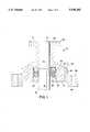
- FIG. 1is a cross-sectional view of a header spool in accordance with the invention mounted to a top of a well casing to permit a well completion or recompletion operation;
- FIG. 2is a cross-sectional view of the header spool shown in FIG. 1 installed on a surface casing spool of an unheaded well, the header spool having a high pressure valve mounted thereto in preparation for a well completion or recompletion operation;
- FIG. 3is a schematic diagram of an apparatus in accordance with the invention mounted to a well that includes horizontal bores, the well being in a condition to be completed for production.
- FIG. 1shows a cross-sectional view of a header spool in accordance with the invention, generally indicated by the reference 10.
- the header spoolhas an upper end 12, a lower end 14 and a passage 16 which extends between the upper end and the lower end.
- the passage 16has a diameter which is at least equal to an inner diameter of a casing 18 to which the header spool 10 is connected.
- the upper end 12is provided with a top flange 20 preferably having an annular groove 22 for accommodating a high pressure O-ring (not illustrated).
- the flange 20is used to attach a high pressure valve for controlling fluid flow from the casing 18, as will be explained below with reference to FIG. 2.
- the lower end 14 of the header spool 10includes an annular recess 24 that is coaxial with the passage 16 and extends upwardly from the lower end 14.
- the annular recess 24preferably includes a spiral thread 26 in its lower end.
- the spiral threadretains a hollow retainer nut 28 for supporting a donut-shaped packing 30 for providing a fluid seal between an outer surface 32 of casing 18 and the header spool 10.
- the packing 30is preferably a chevron packing, well known in the art.
- a steel spacer ring 34Positioned above the packing is a steel spacer ring 34 for spacing the packing 30 away from a top of the annular recess 24 and ensuring good compression of the packing 30 by the hollow retainer nut 28.
- the hollow retainer nut 28is sized to slide over the outer surface 32 of the casing 18 without scoring or abrading the casing.
- the lower end 14 of the header spool 10also includes a bottom flange 36 used to mount the header spool to a surface casing flange as will be explained below.
- the bottom flange 36preferably includes an annular groove 38 for accepting a high pressure O-ring (not illustrated) to provide a fluid seal between the header spool 10 and the casing spool to which the header spool is mounted.
- the header spoolfurther includes a pressure test port 40 which extends through the lower end 14 of the header spool 10 in an area located between the annular recess 24 and the flange 36. Fluid flow through the test port 40 is preferably controlled by a pressure release valve 42, commonly commercially available.
- the pressure test port 40is used to monitor the fluid seal between the header spool 10 and the casing 18 during well completion and recompletion operations, as will be explained below in relation to FIGS. 2 and 3.
- the header spool 10is preferably constructed to withstand fluid pressures about equal to the burst pressure rating of the casing 18 so that well stimulation operations can be conducted at the maximum pressure to which the well can be safely subjected, if desired.
- FIG. 2shows a header spool 10 in accordance with the invention mounted to an unheaded well casing 18.
- the wellhas been drilled, the casing 18 has been sunk in the bore and a surface casing 44 has been "cemented in” in a process well known in the art.
- the surface casing 44includes a surface casing spool 46 adapted to support wellhead equipment when the well is completed and ready for production.
- the header spool 10is mounted to the casing spool 46 after the well casing 18 has been upset, beveled and cleaned up in a well known manner for preparing a casing for the installation of wellhead equipment.
- the spacer ring 34, the chevron packing 30 and the retainer nut 26are installed in the annular recess 24 in the lower end 14 of the header spool 10.
- the retainer nut 26is tightened to securely support the chevron packing 30 in its position.
- the header spoolis carefully lowered over the beveled casing 18 and the chevron packing is forced over the top of the casing to provide a fluid fight seal. Because of the structure of the chevron packing, it is capable of providing a seal that will contain extreme pressures.
- the header spool 10is mounted to the casing 18, it is bolted down to the surface casing spool 46.
- a high pressure valve 48is then mounted to the upper end 12 of the header spool 10.
- the high pressure valve 48must be capable of containing elevated fluid pressures and preferably has a pressure rating that is about equal to the pressure burst rating of the casing 18. Such valves are normally hydraulically operated and are commercially available. After the high pressure valve 48 is mounted to the header spool 10, the installation is ready for pressure testing and well completion operations as explained below.
- header spool 10normally pressure rated for at least 10,000 psi
- surface casing spool 46normally pressure rated for 3-5,000 psi. It must be understood, however, that the surface casing spool is completely isolated from direct fluid pressures because the pressure test port 40 is normally open during pressure testing and well completion or recompletion operations. The surface casing spool is therefore only subjected to a vertical lifting force translated through the header spool 10 from the fluid pressures contained by the high pressure valve 48.
- the cross-sectional area of the casingis considerably smaller than the cross-sectional area at the flange of the surface casing spool 46, the vertical lifting force is distributed over a large area and the surface casing spool 46 can readily withstand the vertical strain of holding down the header spool 10.
- FIG. 3shows a schematic view of a cased well having a configuration exemplary of a well configuration particularly adapted for completion using the apparatus and methods in accordance with the invention.
- the wellincludes a vertical bore 50, a lower horizontal bore 52 and an upper horizontal bore 54.
- the apparatus in accordance with the inventionmay be used to complete any well, regardless of the orientation of the bores. Use of the apparatus and method are particularly beneficial when the well has one or more production zones that require high pressure stimulation, and the production zone(s) are too voluminous in combination to be stimulated in a single high pressure acidizing or fracturing process.
- a header spool 10has been mounted to the cased, unheaded well.
- a high pressure valve 48Mounted to the header spool 10 is a high pressure valve 48.
- an optional fracturing cross connection 56Mounted above the high pressure valve 48 is an optional fracturing cross connection 56, commonly referred to as a "frac cross” or a “goats head”, and referred to as a frac cross below.
- the inventionencompasses a method of completing a cased well for production.
- a typical series of events in the completion of a well for production, such as the well shown in FIG. 3,proceeds as follows:
- the fluid tight seal at the header spool 10is tested by connecting a high pressure pump, typically a "frac pump” (high pressure fracturing pump) to the high pressure valve 48 or the frac cross 56.
- a high pressure pumptypically a "frac pump” (high pressure fracturing pump)
- the cased wellis pressurized to the maximum pressure desired for the stimulation process to be conducted on the well (typically 6-10,000 psi).
- the pressure release valve 42 on the pressure test port 40(see FIG. 2) is opened to ensure that the chevron packing 30 maintains a fluid tight seal around the well casing 18. If no fluid escapes when the pressure release valve 42 is opened, the fluid tight seal is known to be secure. Normally, the pressure release valve 42 is left open during well completion operations so that any leak around the chevron packing 30 is instantly detected.
- a log toolis lowered on a wire line into the well to log the most remote zone in the well bore. For instance, it may be determined that a first production zone 58 requires stimulation to maximize production.
- a casing perforation toolhereinafter referred to as a "perf gun” (not illustrated) is mounted to a top of the frac cross 56 or the high pressure valve 48 and lowered by wire line into the well to the first production zone 58. The casing is then perforated in that zone or a portion of the zone. The perf gun is then removed from the well.
- One or two fracturing linesare connected to the frac cross 56 or the high pressure valve 48.
- a high pressure stimulation cyclewherein acidic and/or abrasive fluids are pumped under elevated pressures (6-10,000 psi) into the first production zone 58 is performed.
- the stimulation fluid in the wellis permitted to flow back through the header spool 10 and the high pressure valve 48.
- the wellmay then be tested to determine the hydrocarbon flow rate from the production zone, or testing may be postponed until the well completion operation is completed.
- an isolation plug or packer 70must be positioned between the production zone 58 and the production zone 60.
- a packer toolis therefore lowered in the well to position the packer or plug 70.
- the second production zone 60is logged by lowering a logging tool into the well casing, and the entire sequence of the process is repeated for each of the production zones 60, 62 and 64.
- header spool 10permits the unobstructed use of any tool which can be used in the casing 18. Well completion procedures can therefore proceed in an uninterrupted sequence. The method therefore provides considerable economy in completing a well for production.
- production tubingeither jointed or continuous tubing
- header spool 10can be run through the header spool 10 into the casing 18.
- Thispermits more sophisticated well completion or recompletion operations including reverse circulation in the case of a "screen out" during a stimulation process, manifolded stimulation processes, etc. which can contribute to more efficient and reliable well completion or recompletion procedures.
- stimulation fluids used to stimulate the uppermost production zone treatedare permitted to flow back through the header spool 10 and the high pressure valve 48.
- a packeris then set at the top of the well bore and the header spool 10 is removed from the surface casing spool 46.
- a wellhead assemblyis then mounted to the wellhead, one or more blowout preventers are installed and the well is cleaned before commencing production.
- a tubing hangeris installed before the wellhead equipment is installed and production tubing is run into the wellhead before hydrocarbon production is commenced.
- header spool 10 in accordance with the inventionmay also be used for recompletion of existing wells having a plurality of production zones which require stimulation and/or which require perforation and stimulation of production zones in unperforated areas of the well casing.
- the procedures described aboveare typically followed in the same sequence as practiced for completing a newly cased well.
Landscapes
- Life Sciences & Earth Sciences (AREA)
- Engineering & Computer Science (AREA)
- Geology (AREA)
- Mining & Mineral Resources (AREA)
- Physics & Mathematics (AREA)
- Environmental & Geological Engineering (AREA)
- Fluid Mechanics (AREA)
- General Life Sciences & Earth Sciences (AREA)
- Geochemistry & Mineralogy (AREA)
- Geophysics (AREA)
- Filling Or Discharging Of Gas Storage Vessels (AREA)
- Physical Or Chemical Processes And Apparatus (AREA)
Abstract
Description
Claims (12)
Priority Applications (2)
| Application Number | Priority Date | Filing Date | Title |
|---|---|---|---|
| US08/328,144US5540282A (en) | 1994-10-21 | 1994-10-21 | Apparatus and method for completing/recompleting production wells |
| US08/640,335US5615739A (en) | 1994-10-21 | 1996-04-30 | Apparatus and method for completing and recompleting wells for production |
Applications Claiming Priority (1)
| Application Number | Priority Date | Filing Date | Title |
|---|---|---|---|
| US08/328,144US5540282A (en) | 1994-10-21 | 1994-10-21 | Apparatus and method for completing/recompleting production wells |
Related Child Applications (1)
| Application Number | Title | Priority Date | Filing Date |
|---|---|---|---|
| US08/640,335DivisionUS5615739A (en) | 1994-10-21 | 1996-04-30 | Apparatus and method for completing and recompleting wells for production |
Publications (1)
| Publication Number | Publication Date |
|---|---|
| US5540282Atrue US5540282A (en) | 1996-07-30 |
Family
ID=23279713
Family Applications (2)
| Application Number | Title | Priority Date | Filing Date |
|---|---|---|---|
| US08/328,144Expired - LifetimeUS5540282A (en) | 1994-10-21 | 1994-10-21 | Apparatus and method for completing/recompleting production wells |
| US08/640,335Expired - LifetimeUS5615739A (en) | 1994-10-21 | 1996-04-30 | Apparatus and method for completing and recompleting wells for production |
Family Applications After (1)
| Application Number | Title | Priority Date | Filing Date |
|---|---|---|---|
| US08/640,335Expired - LifetimeUS5615739A (en) | 1994-10-21 | 1996-04-30 | Apparatus and method for completing and recompleting wells for production |
Country Status (1)
| Country | Link |
|---|---|
| US (2) | US5540282A (en) |
Cited By (24)
| Publication number | Priority date | Publication date | Assignee | Title |
|---|---|---|---|---|
| US5785121A (en)* | 1996-06-12 | 1998-07-28 | Dallas; L. Murray | Blowout preventer protector and method of using same during oil and gas well stimulation |
| US5927403A (en)* | 1997-04-21 | 1999-07-27 | Dallas; L. Murray | Apparatus for increasing the flow of production stimulation fluids through a wellhead |
| US6179053B1 (en)* | 1999-08-12 | 2001-01-30 | L. Murray Dallas | Lockdown mechanism for well tools requiring fixed-point packoff |
| US20030205385A1 (en)* | 2002-02-19 | 2003-11-06 | Duhn Rex E. | Connections for wellhead equipment |
| US20030221823A1 (en)* | 2002-02-19 | 2003-12-04 | Duhn Rex E. | Wellhead isolation tool |
| US6666266B2 (en) | 2002-05-03 | 2003-12-23 | Halliburton Energy Services, Inc. | Screw-driven wellhead isolation tool |
| US6712147B2 (en)* | 2001-11-15 | 2004-03-30 | L. Murray Dallas | Spool for pressure containment used in rigless well completion, re-completion, servicing or workover |
| US20040231856A1 (en)* | 2003-05-13 | 2004-11-25 | Dallas L. Murray | Casing mandrel with well stimulation tool and tubing head spool for use with the casing mandrel |
| US6827147B2 (en) | 2002-05-31 | 2004-12-07 | L. Murray Dallas | Reciprocating lubricator |
| US20050092496A1 (en)* | 2002-02-19 | 2005-05-05 | Duhn Rex E. | Wellhead isolation tool and method of fracturing a well |
| US20050211442A1 (en)* | 2004-03-29 | 2005-09-29 | Mcguire Bob | System and method for low-pressure well completion |
| US20060060349A1 (en)* | 2002-02-19 | 2006-03-23 | Duhn Rex E | Wellhead isolation tool and method of fracturing a well |
| US20060137882A1 (en)* | 2004-12-28 | 2006-06-29 | Mcguire Bob | Blast joint swivel for wellhead isolation tool and method of using same |
| US20070107910A1 (en)* | 2004-03-17 | 2007-05-17 | Mcguire Bob | Hybrid wellhead system and method of use |
| US20070267198A1 (en)* | 2003-05-19 | 2007-11-22 | Stinger Wellhead Protection, Inc. | Casing mandrel for facilitating well completion, re-completion or workover |
| US20080087439A1 (en)* | 2006-10-12 | 2008-04-17 | Stinger Wellhead Protection, Inc. | Configurable wellhead system with permanent fracturing spool and method of use |
| US20090236090A1 (en)* | 2008-03-20 | 2009-09-24 | Stinger Wellhead Protection, Inc. | Erosion Resistant Frac Head |
| US8622121B2 (en) | 2011-02-10 | 2014-01-07 | Vetco Gray Inc. | Reinforced frac tubing head |
| US8820400B2 (en) | 2008-03-20 | 2014-09-02 | Oil States Energy Services, L.L.C. | Erosion resistant frac head |
| US8950485B2 (en) | 2011-07-15 | 2015-02-10 | Ge Oil & Gas Pressure Control Lp | Drilling/frac adapter and method of use |
| US10858902B2 (en) | 2019-04-24 | 2020-12-08 | Oil States Energy Services, L.L.C. | Frac manifold and connector |
| US10895139B2 (en) | 2019-04-24 | 2021-01-19 | Oil States Energy Services, Llc | Frac manifold isolation tool |
| US20220120167A1 (en)* | 2020-10-15 | 2022-04-21 | Bestway Oilfield, Inc. | Adapters for Drilled, Uncompleted Wells |
| US12398809B2 (en) | 2023-08-28 | 2025-08-26 | Bestway Oilfield, Inc. | Dynamic slab gate valves |
Families Citing this family (52)
| Publication number | Priority date | Publication date | Assignee | Title |
|---|---|---|---|---|
| RU2117151C1 (en)* | 1998-03-12 | 1998-08-10 | Закрытое акционерное общество "Алойл" | Method of treating bottom zone of well |
| US20040035582A1 (en)* | 2002-08-22 | 2004-02-26 | Zupanick Joseph A. | System and method for subterranean access |
| US6679322B1 (en) | 1998-11-20 | 2004-01-20 | Cdx Gas, Llc | Method and system for accessing subterranean deposits from the surface |
| US6681855B2 (en) | 2001-10-19 | 2004-01-27 | Cdx Gas, L.L.C. | Method and system for management of by-products from subterranean zones |
| US7025154B2 (en)* | 1998-11-20 | 2006-04-11 | Cdx Gas, Llc | Method and system for circulating fluid in a well system |
| US6425448B1 (en) | 2001-01-30 | 2002-07-30 | Cdx Gas, L.L.P. | Method and system for accessing subterranean zones from a limited surface area |
| US8297377B2 (en) | 1998-11-20 | 2012-10-30 | Vitruvian Exploration, Llc | Method and system for accessing subterranean deposits from the surface and tools therefor |
| US6988548B2 (en) | 2002-10-03 | 2006-01-24 | Cdx Gas, Llc | Method and system for removing fluid from a subterranean zone using an enlarged cavity |
| US6280000B1 (en) | 1998-11-20 | 2001-08-28 | Joseph A. Zupanick | Method for production of gas from a coal seam using intersecting well bores |
| US8376052B2 (en) | 1998-11-20 | 2013-02-19 | Vitruvian Exploration, Llc | Method and system for surface production of gas from a subterranean zone |
| US6662870B1 (en) | 2001-01-30 | 2003-12-16 | Cdx Gas, L.L.C. | Method and system for accessing subterranean deposits from a limited surface area |
| US6454000B1 (en) | 1999-11-19 | 2002-09-24 | Cdx Gas, Llc | Cavity well positioning system and method |
| US7073595B2 (en)* | 2002-09-12 | 2006-07-11 | Cdx Gas, Llc | Method and system for controlling pressure in a dual well system |
| US6708764B2 (en) | 2002-07-12 | 2004-03-23 | Cdx Gas, L.L.C. | Undulating well bore |
| US6598686B1 (en) | 1998-11-20 | 2003-07-29 | Cdx Gas, Llc | Method and system for enhanced access to a subterranean zone |
| US7048049B2 (en) | 2001-10-30 | 2006-05-23 | Cdx Gas, Llc | Slant entry well system and method |
| RU2151863C1 (en)* | 1999-12-03 | 2000-06-27 | Лыков Владимир Иванович | Oil well development method |
| US6412556B1 (en) | 2000-08-03 | 2002-07-02 | Cdx Gas, Inc. | Cavity positioning tool and method |
| US6591903B2 (en) | 2001-12-06 | 2003-07-15 | Eog Resources Inc. | Method of recovery of hydrocarbons from low pressure formations |
| US7360595B2 (en)* | 2002-05-08 | 2008-04-22 | Cdx Gas, Llc | Method and system for underground treatment of materials |
| US6991048B2 (en) | 2002-07-12 | 2006-01-31 | Cdx Gas, Llc | Wellbore plug system and method |
| US6991047B2 (en) | 2002-07-12 | 2006-01-31 | Cdx Gas, Llc | Wellbore sealing system and method |
| US6725922B2 (en) | 2002-07-12 | 2004-04-27 | Cdx Gas, Llc | Ramping well bores |
| US7025137B2 (en)* | 2002-09-12 | 2006-04-11 | Cdx Gas, Llc | Three-dimensional well system for accessing subterranean zones |
| US8333245B2 (en) | 2002-09-17 | 2012-12-18 | Vitruvian Exploration, Llc | Accelerated production of gas from a subterranean zone |
| US6964308B1 (en) | 2002-10-08 | 2005-11-15 | Cdx Gas, Llc | Method of drilling lateral wellbores from a slant well without utilizing a whipstock |
| US6918452B2 (en)* | 2002-12-17 | 2005-07-19 | Vetco Gray Inc. | Drill string shutoff valve |
| US7017682B2 (en)* | 2002-12-17 | 2006-03-28 | Vetco Gray Inc. | Drill string shutoff valve |
| RU2213210C1 (en)* | 2002-12-30 | 2003-09-27 | Открытое акционерное общество "Шешмаойл" | Method of development of formation with difficult to recover oil reserves |
| US7264048B2 (en)* | 2003-04-21 | 2007-09-04 | Cdx Gas, Llc | Slot cavity |
| US7134494B2 (en)* | 2003-06-05 | 2006-11-14 | Cdx Gas, Llc | Method and system for recirculating fluid in a well system |
| RU2230894C1 (en)* | 2003-09-29 | 2004-06-20 | Открытое акционерное общество "Татнефть" им. В.Д. Шашина | Method for extraction of oil reservoir |
| RU2235865C1 (en)* | 2003-09-29 | 2004-09-10 | Открытое акционерное общество "Татнефть" им. В.Д. Шашина | Method for treatment of face-adjacent section of bed of horizontal well shaft and device for realization of said method |
| US7100687B2 (en)* | 2003-11-17 | 2006-09-05 | Cdx Gas, Llc | Multi-purpose well bores and method for accessing a subterranean zone from the surface |
| US7163063B2 (en) | 2003-11-26 | 2007-01-16 | Cdx Gas, Llc | Method and system for extraction of resources from a subterranean well bore |
| US7419223B2 (en)* | 2003-11-26 | 2008-09-02 | Cdx Gas, Llc | System and method for enhancing permeability of a subterranean zone at a horizontal well bore |
| US20060201715A1 (en)* | 2003-11-26 | 2006-09-14 | Seams Douglas P | Drilling normally to sub-normally pressured formations |
| US20060201714A1 (en)* | 2003-11-26 | 2006-09-14 | Seams Douglas P | Well bore cleaning |
| US7207395B2 (en)* | 2004-01-30 | 2007-04-24 | Cdx Gas, Llc | Method and system for testing a partially formed hydrocarbon well for evaluation and well planning refinement |
| US7207390B1 (en) | 2004-02-05 | 2007-04-24 | Cdx Gas, Llc | Method and system for lining multilateral wells |
| US7222670B2 (en)* | 2004-02-27 | 2007-05-29 | Cdx Gas, Llc | System and method for multiple wells from a common surface location |
| RU2258134C1 (en)* | 2004-08-05 | 2005-08-10 | Открытое акционерное общество "Татнефть" им. В.Д.Шашина | Treatment method for bottomhole zone of injection well |
| US7353877B2 (en)* | 2004-12-21 | 2008-04-08 | Cdx Gas, Llc | Accessing subterranean resources by formation collapse |
| US7299864B2 (en)* | 2004-12-22 | 2007-11-27 | Cdx Gas, Llc | Adjustable window liner |
| US7373984B2 (en) | 2004-12-22 | 2008-05-20 | Cdx Gas, Llc | Lining well bore junctions |
| US7571771B2 (en)* | 2005-05-31 | 2009-08-11 | Cdx Gas, Llc | Cavity well system |
| RU2295631C1 (en)* | 2005-06-22 | 2007-03-20 | Александр Николаевич Дроздов | Immersed pump-ejector system for extracting oil |
| CN100434653C (en)* | 2006-07-28 | 2008-11-19 | 辽河石油勘探局 | Blasting type cave well completion technological method of coal layer gas well |
| US7647989B2 (en)* | 2008-06-02 | 2010-01-19 | Vetco Gray Inc. | Backup safety flow control system for concentric drill string |
| WO2009154881A1 (en)* | 2008-06-19 | 2009-12-23 | Cameron International Corporation | Frac adapter for wellhead |
| WO2014031223A1 (en) | 2012-08-23 | 2014-02-27 | Exxonmobil Upstream Research Company | Systems and methods for re-completing multi-zone wells |
| US9644449B2 (en)* | 2013-06-07 | 2017-05-09 | Cameron International Corporation | Geothermal integrated expansion spool assembly |
Citations (8)
| Publication number | Priority date | Publication date | Assignee | Title |
|---|---|---|---|---|
| US3561531A (en)* | 1969-08-21 | 1971-02-09 | Exxon Production Research Co | Method and apparatus for landing well pipe in permafrost formations |
| US3738426A (en)* | 1971-02-16 | 1973-06-12 | Rockwell Mfg Co | Subsidence wellhead assembly and method |
| US4512410A (en)* | 1983-09-16 | 1985-04-23 | Forester Buford G | Geothermal expansion wellhead system |
| US4513816A (en)* | 1982-01-08 | 1985-04-30 | Societe Nationale Elf Aquitaine (Production) | Sealing system for a well bore in which a hot fluid is circulated |
| US4703807A (en)* | 1982-11-05 | 1987-11-03 | Hydril Company | Rotatable ball valve apparatus and method |
| US5114158A (en)* | 1990-11-19 | 1992-05-19 | Le Tri C | Packing assembly for oilfield equipment and method |
| US5205356A (en)* | 1990-12-27 | 1993-04-27 | Abb Vetco Gray Inc. | Well starter head |
| US5394943A (en)* | 1993-11-05 | 1995-03-07 | Harrington; Donald R. | Subsurface shutdown safety valve and arrangement system |
Family Cites Families (4)
| Publication number | Priority date | Publication date | Assignee | Title |
|---|---|---|---|---|
| USRE23383E (en)* | 1951-07-03 | Camras | ||
| US4600056A (en)* | 1984-03-26 | 1986-07-15 | Rejane M. Burton | Method and apparatus for completing well |
| US4605067A (en)* | 1984-03-26 | 1986-08-12 | Rejane M. Burton | Method and apparatus for completing well |
| US5456320A (en)* | 1993-12-06 | 1995-10-10 | Total Tool, Inc. | Casing seal and spool for use in fracturing wells |
- 1994
- 1994-10-21USUS08/328,144patent/US5540282A/ennot_activeExpired - Lifetime
- 1996
- 1996-04-30USUS08/640,335patent/US5615739A/ennot_activeExpired - Lifetime
Patent Citations (8)
| Publication number | Priority date | Publication date | Assignee | Title |
|---|---|---|---|---|
| US3561531A (en)* | 1969-08-21 | 1971-02-09 | Exxon Production Research Co | Method and apparatus for landing well pipe in permafrost formations |
| US3738426A (en)* | 1971-02-16 | 1973-06-12 | Rockwell Mfg Co | Subsidence wellhead assembly and method |
| US4513816A (en)* | 1982-01-08 | 1985-04-30 | Societe Nationale Elf Aquitaine (Production) | Sealing system for a well bore in which a hot fluid is circulated |
| US4703807A (en)* | 1982-11-05 | 1987-11-03 | Hydril Company | Rotatable ball valve apparatus and method |
| US4512410A (en)* | 1983-09-16 | 1985-04-23 | Forester Buford G | Geothermal expansion wellhead system |
| US5114158A (en)* | 1990-11-19 | 1992-05-19 | Le Tri C | Packing assembly for oilfield equipment and method |
| US5205356A (en)* | 1990-12-27 | 1993-04-27 | Abb Vetco Gray Inc. | Well starter head |
| US5394943A (en)* | 1993-11-05 | 1995-03-07 | Harrington; Donald R. | Subsurface shutdown safety valve and arrangement system |
Cited By (67)
| Publication number | Priority date | Publication date | Assignee | Title |
|---|---|---|---|---|
| US5785121A (en)* | 1996-06-12 | 1998-07-28 | Dallas; L. Murray | Blowout preventer protector and method of using same during oil and gas well stimulation |
| US5927403A (en)* | 1997-04-21 | 1999-07-27 | Dallas; L. Murray | Apparatus for increasing the flow of production stimulation fluids through a wellhead |
| US6179053B1 (en)* | 1999-08-12 | 2001-01-30 | L. Murray Dallas | Lockdown mechanism for well tools requiring fixed-point packoff |
| US6712147B2 (en)* | 2001-11-15 | 2004-03-30 | L. Murray Dallas | Spool for pressure containment used in rigless well completion, re-completion, servicing or workover |
| US7726393B2 (en) | 2002-02-19 | 2010-06-01 | Duhn Oil Tool, Inc. | Wellhead isolation tool and wellhead assembly incorporating the same |
| US8272433B2 (en) | 2002-02-19 | 2012-09-25 | Seaboard International Inc. | Wellhead isolation tool and wellhead assembly incorporating the same |
| US20030221823A1 (en)* | 2002-02-19 | 2003-12-04 | Duhn Rex E. | Wellhead isolation tool |
| US8863829B2 (en) | 2002-02-19 | 2014-10-21 | Seaboard International Inc. | Wellhead isolation tool and wellhead assembly incorporating the same |
| US7322407B2 (en) | 2002-02-19 | 2008-01-29 | Duhn Oil Tool, Inc. | Wellhead isolation tool and method of fracturing a well |
| US20050092496A1 (en)* | 2002-02-19 | 2005-05-05 | Duhn Rex E. | Wellhead isolation tool and method of fracturing a well |
| US6920925B2 (en) | 2002-02-19 | 2005-07-26 | Duhn Oil Tool, Inc. | Wellhead isolation tool |
| US8333237B2 (en) | 2002-02-19 | 2012-12-18 | Seaboard International Inc. | Wellhead isolation tool and wellhead assembly incorporating the same |
| US20060060349A1 (en)* | 2002-02-19 | 2006-03-23 | Duhn Rex E | Wellhead isolation tool and method of fracturing a well |
| US20080093067A1 (en)* | 2002-02-19 | 2008-04-24 | Duhn Oil Tool, Inc. | Wellhead isolation tool and method of fracturing a well |
| US20100193178A1 (en)* | 2002-02-19 | 2010-08-05 | Duhn Rex E | Wellhead isolation tool and wellhead assembly incorporating the same |
| US20070272402A1 (en)* | 2002-02-19 | 2007-11-29 | Duhn Rex E | Wellhead isolation tool, wellhead assembly incorporating the same, and method of fracturing a well |
| US7520322B2 (en) | 2002-02-19 | 2009-04-21 | Duhn Oil Tool, Inc. | Wellhead isolation tool and method of fracturing a well |
| US20030205385A1 (en)* | 2002-02-19 | 2003-11-06 | Duhn Rex E. | Connections for wellhead equipment |
| US7493944B2 (en) | 2002-02-19 | 2009-02-24 | Duhn Oil Tool, Inc. | Wellhead isolation tool and method of fracturing a well |
| US7416020B2 (en) | 2002-02-19 | 2008-08-26 | Duhn Oil Tool, Inc. | Wellhead isolation tool, wellhead assembly incorporating the same, and method of fracturing a well |
| US6666266B2 (en) | 2002-05-03 | 2003-12-23 | Halliburton Energy Services, Inc. | Screw-driven wellhead isolation tool |
| US6827147B2 (en) | 2002-05-31 | 2004-12-07 | L. Murray Dallas | Reciprocating lubricator |
| US7237615B2 (en) | 2003-05-13 | 2007-07-03 | Stinger Wellhead Protection, Inc. | Casing mandrel with well stimulation tool and tubing head spool for use with the casing mandrel |
| US7921923B2 (en) | 2003-05-13 | 2011-04-12 | Stinger Wellhead Protection, Inc. | Casing mandrel for facilitating well completion, re-completion or workover |
| US20040231856A1 (en)* | 2003-05-13 | 2004-11-25 | Dallas L. Murray | Casing mandrel with well stimulation tool and tubing head spool for use with the casing mandrel |
| US20060237193A1 (en)* | 2003-05-13 | 2006-10-26 | Oil States Energy Services, Inc. | Casing mandrel with well stimulation tool and tubing head spool for use with the casing mandrel |
| US20100012329A1 (en)* | 2003-05-13 | 2010-01-21 | Stinger Wellhead Protection, Inc. | Casing mandrel for facilitating well completion, re-completion or workover |
| US8157005B2 (en) | 2003-05-13 | 2012-04-17 | Stinger Wellhead Protection, Inc. | Casing mandrel for facilitating well completion, re-completion or workover |
| US7066269B2 (en) | 2003-05-13 | 2006-06-27 | H W C Energy Services, Inc. | Casing mandrel with well stimulation tool and tubing head spool for use with the casing mandrel |
| US20110180252A1 (en)* | 2003-05-13 | 2011-07-28 | Stinger Wellhead Protection, Inc. | Casing mandrel for facilitating well completion, re-completion or workover |
| US7422070B2 (en) | 2003-05-13 | 2008-09-09 | Stinger Wellhead Protection, Inc. | Casing mandrel with well stimulation tool and tubing head spool for use with the casing mandrel |
| US7604058B2 (en) | 2003-05-19 | 2009-10-20 | Stinger Wellhead Protection, Inc. | Casing mandrel for facilitating well completion, re-completion or workover |
| US20070267198A1 (en)* | 2003-05-19 | 2007-11-22 | Stinger Wellhead Protection, Inc. | Casing mandrel for facilitating well completion, re-completion or workover |
| US7721808B2 (en) | 2004-03-17 | 2010-05-25 | Stinger Wellhead Protection, Inc. | Hybrid wellhead system and method of use |
| US20100218939A1 (en)* | 2004-03-17 | 2010-09-02 | Stinger Wellhead Protection, Inc. | Hybrid wellhead system and method of use |
| US20110198074A1 (en)* | 2004-03-17 | 2011-08-18 | Stinger Wellhead Protection, Inc. | Hybrid wellhead system and method of use |
| US7395867B2 (en) | 2004-03-17 | 2008-07-08 | Stinger Wellhead Protection, Inc. | Hybrid wellhead system and method of use |
| US7905293B2 (en) | 2004-03-17 | 2011-03-15 | Stinger Wellhead Protection, Inc. | Hybrid wellhead system and method of use |
| US7481269B2 (en) | 2004-03-17 | 2009-01-27 | Stinger Wellhead Protection, Inc. | Hybrid wellhead system and method of use |
| US8118090B2 (en) | 2004-03-17 | 2012-02-21 | Stinger Wellhead Protection, Inc. | Hybrid wellhead system and method of use |
| US20080087415A1 (en)* | 2004-03-17 | 2008-04-17 | Stinger Wellhead Protection, Inc. | Hybrid wellhead system and method of use |
| US20070107910A1 (en)* | 2004-03-17 | 2007-05-17 | Mcguire Bob | Hybrid wellhead system and method of use |
| US7296631B2 (en) | 2004-03-29 | 2007-11-20 | Stinger Wellhead Protection, Inc. | System and method for low-pressure well completion |
| US20070158077A1 (en)* | 2004-03-29 | 2007-07-12 | Stinger Wellhead Protection, Inc. | System and method for low-pressure well completion |
| US20050211442A1 (en)* | 2004-03-29 | 2005-09-29 | Mcguire Bob | System and method for low-pressure well completion |
| US20070289748A1 (en)* | 2004-03-29 | 2007-12-20 | Hwces International | System and method for low-pressure well completion |
| US7886833B2 (en) | 2004-03-29 | 2011-02-15 | Stinger Wellhead Protection, Inc. | System and method for low-pressure well completion |
| US7278490B2 (en) | 2004-12-28 | 2007-10-09 | Stinger Wellhead Protection, Inc. | Blast joint swivel for wellhead isolation tool and method of using same |
| US20060137882A1 (en)* | 2004-12-28 | 2006-06-29 | Mcguire Bob | Blast joint swivel for wellhead isolation tool and method of using same |
| US20090283277A1 (en)* | 2006-10-12 | 2009-11-19 | Stinger Wellhead Protection, Inc. | Configurable wellhead system with permanent fracturing spool and method of use |
| US7857062B2 (en) | 2006-10-12 | 2010-12-28 | Stinger Wellhead Protection, Inc. | Configurable wellhead system with permanent fracturing spool and method of use |
| US7578351B2 (en) | 2006-10-12 | 2009-08-25 | Stinger Wellhead Protection, Inc. | Configurable wellhead system with permanent fracturing spool and method of use |
| US20080087439A1 (en)* | 2006-10-12 | 2008-04-17 | Stinger Wellhead Protection, Inc. | Configurable wellhead system with permanent fracturing spool and method of use |
| US20100326648A1 (en)* | 2008-03-20 | 2010-12-30 | Stinger Wellhead Protection, Inc. | Erosion resistant frac head |
| US8016031B2 (en) | 2008-03-20 | 2011-09-13 | Stinger Wellhead Protection, Inc. | Erosion resistant frac head |
| US7789133B2 (en) | 2008-03-20 | 2010-09-07 | Stinger Wellhead Protection, Inc. | Erosion resistant frac head |
| US8820400B2 (en) | 2008-03-20 | 2014-09-02 | Oil States Energy Services, L.L.C. | Erosion resistant frac head |
| US20090236090A1 (en)* | 2008-03-20 | 2009-09-24 | Stinger Wellhead Protection, Inc. | Erosion Resistant Frac Head |
| US8622121B2 (en) | 2011-02-10 | 2014-01-07 | Vetco Gray Inc. | Reinforced frac tubing head |
| US8950485B2 (en) | 2011-07-15 | 2015-02-10 | Ge Oil & Gas Pressure Control Lp | Drilling/frac adapter and method of use |
| US10858902B2 (en) | 2019-04-24 | 2020-12-08 | Oil States Energy Services, L.L.C. | Frac manifold and connector |
| US10895139B2 (en) | 2019-04-24 | 2021-01-19 | Oil States Energy Services, Llc | Frac manifold isolation tool |
| US11428088B2 (en) | 2019-04-24 | 2022-08-30 | Oil States Energy Services, L.L.C. | Frac manifold isolation tool |
| US11585199B2 (en) | 2019-04-24 | 2023-02-21 | Oil States Energy Services, L.L.C. | Frac manifold isolation tool |
| US20220120167A1 (en)* | 2020-10-15 | 2022-04-21 | Bestway Oilfield, Inc. | Adapters for Drilled, Uncompleted Wells |
| US11913313B2 (en)* | 2020-10-15 | 2024-02-27 | Bestway Oilfield, Inc. | Adapters for drilled, uncompleted wells |
| US12398809B2 (en) | 2023-08-28 | 2025-08-26 | Bestway Oilfield, Inc. | Dynamic slab gate valves |
Also Published As
| Publication number | Publication date |
|---|---|
| US5615739A (en) | 1997-04-01 |
Similar Documents
| Publication | Publication Date | Title |
|---|---|---|
| US5540282A (en) | Apparatus and method for completing/recompleting production wells | |
| US7237615B2 (en) | Casing mandrel with well stimulation tool and tubing head spool for use with the casing mandrel | |
| US7604058B2 (en) | Casing mandrel for facilitating well completion, re-completion or workover | |
| CA2434804C (en) | Multi-lock adapters for independent screwed wellheads and methods of using same | |
| US7886833B2 (en) | System and method for low-pressure well completion | |
| RU2413837C2 (en) | Procedure for maintaining pressure in borehole of well (versions) and device for its implementation | |
| US6626245B1 (en) | Blowout preventer protector and method of using same | |
| CA2434801C (en) | Adapters for double-locking casing mandrel and method of using same | |
| CA2335677C (en) | Seal assembly for dual string coil tubing injection and method of use | |
| CA2118335C (en) | Apparatus and method for completing and recompleting wells for production | |
| US20250230744A1 (en) | Pressure testing a wellhead | |
| CA2532295A1 (en) | Packer cups |
Legal Events
| Date | Code | Title | Description |
|---|---|---|---|
| STCF | Information on status: patent grant | Free format text:PATENTED CASE | |
| FEPP | Fee payment procedure | Free format text:PAYOR NUMBER ASSIGNED (ORIGINAL EVENT CODE: ASPN); ENTITY STATUS OF PATENT OWNER: LARGE ENTITY | |
| FEPP | Fee payment procedure | Free format text:PAYER NUMBER DE-ASSIGNED (ORIGINAL EVENT CODE: RMPN); ENTITY STATUS OF PATENT OWNER: LARGE ENTITY Free format text:PAYOR NUMBER ASSIGNED (ORIGINAL EVENT CODE: ASPN); ENTITY STATUS OF PATENT OWNER: LARGE ENTITY | |
| FPAY | Fee payment | Year of fee payment:4 | |
| FPAY | Fee payment | Year of fee payment:8 | |
| AS | Assignment | Owner name:HWCES INTERNATIONAL, TEXAS Free format text:ASSIGNMENT OF ASSIGNORS INTEREST;ASSIGNOR:DALLAS, L. MURRAY;REEL/FRAME:016712/0677 Effective date:20050501 | |
| AS | Assignment | Owner name:HWC ENERGY SERVICES, INC., TEXAS Free format text:ASSIGNMENT OF ASSIGNORS INTEREST;ASSIGNOR:HWCES INTERNATIONAL;REEL/FRAME:017636/0559 Effective date:20060228 | |
| AS | Assignment | Owner name:OIL STATES ENERGY SERVICES, INC, TEXAS Free format text:CHANGE OF NAME;ASSIGNOR:HWC ENERGY SERVICE, INC.;REEL/FRAME:017957/0310 Effective date:20060309 | |
| AS | Assignment | Owner name:STINGER WELLHEAD PROTECTION, INC., TEXAS Free format text:ASSIGNMENT OF ASSIGNORS INTEREST;ASSIGNOR:OIL STATES ENERGY SERVICES, INC.;REEL/FRAME:018767/0230 Effective date:20061219 | |
| AS | Assignment | Owner name:STINGER WELLHEAD PROTECTION, INC., OKLAHOMA Free format text:CHANGE OF ASSIGNEE ADDRESS;ASSIGNOR:STINGER WELLHEAD PROTECTION, INC.;REEL/FRAME:019588/0172 Effective date:20070716 Owner name:STINGER WELLHEAD PROTECTION, INC.,OKLAHOMA Free format text:CHANGE OF ASSIGNEE ADDRESS;ASSIGNOR:STINGER WELLHEAD PROTECTION, INC.;REEL/FRAME:019588/0172 Effective date:20070716 | |
| FEPP | Fee payment procedure | Free format text:PAT HOLDER NO LONGER CLAIMS SMALL ENTITY STATUS, ENTITY STATUS SET TO UNDISCOUNTED (ORIGINAL EVENT CODE: STOL); ENTITY STATUS OF PATENT OWNER: LARGE ENTITY | |
| REFU | Refund | Free format text:REFUND - PAYMENT OF MAINTENANCE FEE, 12TH YR, SMALL ENTITY (ORIGINAL EVENT CODE: R2553); ENTITY STATUS OF PATENT OWNER: LARGE ENTITY | |
| FPAY | Fee payment | Year of fee payment:12 | |
| FEPP | Fee payment procedure | Free format text:ENTITY STATUS SET TO UNDISCOUNTED (ORIGINAL EVENT CODE: BIG.); ENTITY STATUS OF PATENT OWNER: LARGE ENTITY | |
| AS | Assignment | Owner name:OIL STATES ENERGY SERVICES, L.L.C., TEXAS Free format text:MERGER;ASSIGNOR:STINGER WELLHEAD PROTECTION, INCORPORATED;REEL/FRAME:029130/0379 Effective date:20111231 |