US5540220A - Pressure-limited, time-cycled pulmonary ventilation with volume-cycle override - Google Patents
Pressure-limited, time-cycled pulmonary ventilation with volume-cycle overrideDownload PDFInfo
- Publication number
- US5540220A US5540220AUS08/351,833US35183394AUS5540220AUS 5540220 AUS5540220 AUS 5540220AUS 35183394 AUS35183394 AUS 35183394AUS 5540220 AUS5540220 AUS 5540220A
- Authority
- US
- United States
- Prior art keywords
- value
- flow rate
- signal
- inspiratory
- pressure
- Prior art date
- Legal status (The legal status is an assumption and is not a legal conclusion. Google has not performed a legal analysis and makes no representation as to the accuracy of the status listed.)
- Expired - Lifetime
Links
- 230000002685pulmonary effectEffects0.000titleclaimsabstractdescription15
- 238000009423ventilationMethods0.000titleclaimsdescription17
- 230000003434inspiratory effectEffects0.000claimsabstractdescription186
- 230000000241respiratory effectEffects0.000claimsabstractdescription36
- 230000004044responseEffects0.000claimsabstractdescription35
- 230000007246mechanismEffects0.000claimsdescription15
- 238000000034methodMethods0.000claimsdescription12
- 230000006872improvementEffects0.000claimsdescription6
- 238000004891communicationMethods0.000claimsdescription5
- 239000012530fluidSubstances0.000claimsdescription3
- 230000035945sensitivityEffects0.000claimsdescription3
- 230000000737periodic effectEffects0.000claimsdescription2
- 239000007789gasSubstances0.000description48
- 230000006870functionEffects0.000description19
- 238000010438heat treatmentMethods0.000description16
- 210000004072lungAnatomy0.000description9
- 230000001105regulatory effectEffects0.000description9
- 230000008901benefitEffects0.000description7
- 238000005259measurementMethods0.000description6
- 230000010354integrationEffects0.000description5
- 238000002156mixingMethods0.000description5
- 239000004094surface-active agentSubstances0.000description5
- 230000000977initiatory effectEffects0.000description4
- 238000013459approachMethods0.000description3
- 230000007423decreaseEffects0.000description3
- 238000013461designMethods0.000description3
- 239000000203mixtureSubstances0.000description3
- 238000012545processingMethods0.000description3
- 208000000203Hyaline Membrane DiseaseDiseases0.000description2
- 208000032571Infant acute respiratory distress syndromeDiseases0.000description2
- 206010028974Neonatal respiratory distress syndromeDiseases0.000description2
- 230000003321amplificationEffects0.000description2
- QVGXLLKOCUKJST-UHFFFAOYSA-Natomic oxygenChemical compound[O]QVGXLLKOCUKJST-UHFFFAOYSA-N0.000description2
- 230000033228biological regulationEffects0.000description2
- 238000012937correctionMethods0.000description2
- 230000000694effectsEffects0.000description2
- 238000005399mechanical ventilationMethods0.000description2
- 238000012544monitoring processMethods0.000description2
- 201000002652newborn respiratory distress syndromeDiseases0.000description2
- 238000003199nucleic acid amplification methodMethods0.000description2
- 239000001301oxygenSubstances0.000description2
- 229910052760oxygenInorganic materials0.000description2
- 230000008569processEffects0.000description2
- 230000002269spontaneous effectEffects0.000description2
- 230000003519ventilatory effectEffects0.000description2
- 206010061688BarotraumaDiseases0.000description1
- 208000027418Wounds and injuryDiseases0.000description1
- 238000004364calculation methodMethods0.000description1
- 230000000295complement effectEffects0.000description1
- 230000001143conditioned effectEffects0.000description1
- 239000000470constituentSubstances0.000description1
- 238000010276constructionMethods0.000description1
- 230000001276controlling effectEffects0.000description1
- 230000006378damageEffects0.000description1
- 238000002716delivery methodMethods0.000description1
- 238000011161developmentMethods0.000description1
- 238000010586diagramMethods0.000description1
- 208000014674injuryDiseases0.000description1
- 238000005304joiningMethods0.000description1
- 238000007726management methodMethods0.000description1
- 238000004519manufacturing processMethods0.000description1
- 238000012986modificationMethods0.000description1
- 230000004048modificationEffects0.000description1
- 230000029058respiratory gaseous exchangeEffects0.000description1
- 208000023504respiratory system diseaseDiseases0.000description1
- 239000007787solidSubstances0.000description1
- 230000001360synchronised effectEffects0.000description1
- 230000000007visual effectEffects0.000description1
Images


Classifications
- A—HUMAN NECESSITIES
- A61—MEDICAL OR VETERINARY SCIENCE; HYGIENE
- A61M—DEVICES FOR INTRODUCING MEDIA INTO, OR ONTO, THE BODY; DEVICES FOR TRANSDUCING BODY MEDIA OR FOR TAKING MEDIA FROM THE BODY; DEVICES FOR PRODUCING OR ENDING SLEEP OR STUPOR
- A61M16/00—Devices for influencing the respiratory system of patients by gas treatment, e.g. ventilators; Tracheal tubes
- A61M16/021—Devices for influencing the respiratory system of patients by gas treatment, e.g. ventilators; Tracheal tubes operated by electrical means
- A61M16/022—Control means therefor
- A61M16/024—Control means therefor including calculation means, e.g. using a processor
- A—HUMAN NECESSITIES
- A61—MEDICAL OR VETERINARY SCIENCE; HYGIENE
- A61M—DEVICES FOR INTRODUCING MEDIA INTO, OR ONTO, THE BODY; DEVICES FOR TRANSDUCING BODY MEDIA OR FOR TAKING MEDIA FROM THE BODY; DEVICES FOR PRODUCING OR ENDING SLEEP OR STUPOR
- A61M16/00—Devices for influencing the respiratory system of patients by gas treatment, e.g. ventilators; Tracheal tubes
- A61M16/0051—Devices for influencing the respiratory system of patients by gas treatment, e.g. ventilators; Tracheal tubes with alarm devices
- A—HUMAN NECESSITIES
- A61—MEDICAL OR VETERINARY SCIENCE; HYGIENE
- A61M—DEVICES FOR INTRODUCING MEDIA INTO, OR ONTO, THE BODY; DEVICES FOR TRANSDUCING BODY MEDIA OR FOR TAKING MEDIA FROM THE BODY; DEVICES FOR PRODUCING OR ENDING SLEEP OR STUPOR
- A61M16/00—Devices for influencing the respiratory system of patients by gas treatment, e.g. ventilators; Tracheal tubes
- A61M16/0003—Accessories therefor, e.g. sensors, vibrators, negative pressure
- A61M2016/003—Accessories therefor, e.g. sensors, vibrators, negative pressure with a flowmeter
- A61M2016/0033—Accessories therefor, e.g. sensors, vibrators, negative pressure with a flowmeter electrical
- A61M2016/0036—Accessories therefor, e.g. sensors, vibrators, negative pressure with a flowmeter electrical in the breathing tube and used in both inspiratory and expiratory phase
Definitions
- This inventionrelates to the field of mechanical pulmonary ventilation.
- the present inventionrelates to a method and apparatus for pulmonary ventilation support which represents an improvement in the mode of mechanical ventilation known as "pressure-limited, time-cycled" ventilation.
- Pressure-limited, time-cycled mechanical ventilationis well known in the art. Briefly described, in this mode of ventilation, a pressure limit is applied, during the inspiratory phase of respiration, to limit the peak inspiratory pressure to a selected (adjustable) maximum value. Once this maximum pressure value is reached, airway pressure is held at that value for the remaining duration of the selected (adjustable) inspiratory time period, during which gas continues to flow to the patient, albeit at a decelerating flow rate as the lungs fill. At the end of the selected inspiratory time period, the exhalation valve of the ventilator is opened for a selected (adjustable) expiratory time period, allowing exhalation either to ambient pressure, or to a positive end expiratory pressure ("PEEP").
- PEEPpositive end expiratory pressure
- Pressure-limited, time-cycled ventilationis distinct from volume-cycled ventilation, in which the inspiratory flow is stopped after a preselected tidal volume is delivered (to the patient and to the patient circuit), independently of peak inspiratory pressure, inspiratory time, and inspiratory flow rate.
- Pressure-limited, time-cycled ventilationis often used for infants and neonates, particularly patients with hyaline membrane disease.
- An advantage of this mode of ventilationis that the pressure limitation feature reduces the risk of barotrauma.
- the treatment of neonates with hyaline membrane disease and other respiratory disorders attributed to incomplete pulmonary developmentusually includes the administration of surfactants to the patient's lungs.
- the use of a surfactanttypically results in an increase in the compliance of the lungs, resulting in greater tidal volume delivered to the lungs at any given peak inspiratory pressure. Consequently, to prevent over-expansion of the lungs (pulmonary hyperdistention), the peak inspiratory pressure limit must be periodically lowered as the surfactant takes effect.
- new surfactants and surfactant delivery methodshave become available that produce dramatically more rapid and pronounced increases in compliance than have heretofore been possible, thereby requiring more rapid and frequent adjustments of the peak inspiratory pressure limit. Failure to adjust this limit properly could result in the delivering of a larger tidal volume to the patient, at a selected pressure limit, than the patient can bear without injury.
- U.S. Pat. No. 3,523,527--Fosterdiscloses a time-cycled ventilator which delivers an inspiratory breath for a preselected inspiratory time period, unless, before the expiration of the time period, a preselected pressure limit or a preselected volume limit is reached.
- the inspiratory flowis stopped whenever the first of three parametric limits (time, pressure, or volume) is reached; for any given breath, the ventilator may therefore be time-cycled, pressure-cycled, or volume-cycled.
- the ventilatoris not pressure-limited, in that the inspiratory phase is not continued at the maximum pressure until the inspiratory time period has elapsed; the inspiratory phase is simply terminated.
- U.S. Pat. No. 3,633,576--Gorsuchdescribes a volume-cycled ventilator that employs a time-cycled, pressure-limited ventilator as a pressurized gas source.
- U.S. Pat. No. 3,729,000--Belldiscloses a volume-cycled ventilator that maintains a constant delivered volume in the face of changing system compliance.
- U.S. Pat. No. 3,961,627--Ernst et al.discloses a ventilator with pressure regulation during a first part of the inspiratory period, followed by flow regulation during a second part of the inspiratory period. A pressure limit and a flow rate limit are thus applied sequentially within an inspiratory time period, with the object of delivering the desired volume at the end of the inspiratory period.
- U.S. Pat. No. 3,972,327--Ernst et al.discloses a volume-cycled ventilator with a pressure-limiting override feature.
- the ventilatorcan switch from flow rate-regulated inspiratory flow to a pressure-limited flow if, during inspiration, the buccal pressure, or the rate of increase of buccal pressure, exceeds preselected limits.
- U.S. Pat. No. 5,129,390--Chopin et al.discloses a volume-cycled ventilator that establishes an optimum minute volume, with a set limit for proximal pressure ("airway passage pressure").
- the present inventionis an improved pressure-limited, time-cycled ventilator, wherein the improvement comprises means for applying a preselected tidal volume limit as a back-up or override limit, in addition to, and simultaneously with, the preselected pressure limit.
- the inventionis embodied in a ventilator that provides a selectable constant inspiratory flow rate to a patient.
- the proximal pressure of the patientis monitored during inspiration, and a proximal pressure signal is generated.
- a pressure control mechanismincludes an exhalation valve that remains closed during the inspiratory phase, until the proximal pressure, as indicated by the proximal pressure signal, reaches a preselected limit, at which point the exhalation valve opens sufficiently to vent pressure over the limit, thereby maintaining the pressure substantially at the limit.
- PEEPpositive end expiratory pressure
- the improvement according to the present inventionis the addition of means for terminating the inspiratory phase prior to the elapsing of its preselected time period in response to a delivered tidal volume that meets or exceeds a preselected limit, so that the time-cycling function is, in essence, over-ridden by a volume-cycling function.
- the inspiratory phaseis terminated either by the elapsing of the preselected inspiratory time period, or by the reaching of the preselected tidal volume limit, whichever first occurs. In either case, the proximal pressure is limited so as not to exceed its preselected maximum.
- the above-described improvementis carried out, in a preferred embodiment of the invention, by providing a flow sensor in the patient circuit, between the patient and the ventilator.
- the flow sensorgenerates an inhalation flow-indicative signal during inspiration.
- the inhalation flow-indicative signalhas a value that is related to the instantaneous flow rate of the gas inhaled by the patient from the inspiratory gas stream provided by the ventilator.
- This instantaneous inhalation flow rate valueis electronically integrated to obtain a substantially real-time value indicative of the measured instantaneous tidal volume.
- the measured tidal volume valueis periodically compared with an electronically stored tidal volume limit value.
- the inspiratory phaseis allowed to continue. If, however, the measured value equals or exceeds the stored limit value, the inspiratory phase is terminated, and the expiratory phase is commenced, even if the preselected inspiratory time period has not elapsed.
- the stored tidal volume limit valuemay be changed, as desired by the clinician, by an operator control.
- the subject inventionoffers all of the well-recognized advantages of time-cycled, pressure-limited ventilation, while also offering the further advantage of a volume-cycling function that can override the time-cycling function, and that is useful in situations in which pulmonary hyperdistention is of concern.
- FIG. 1is a graphical representation of the operation of a pressure-limited, time-cycled ventilator
- FIG. 2is a graphical representation of the operation of a volume-cycled ventilator
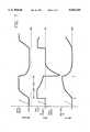
- FIG. 3is a graphical representation of the operation of a pressure-limited, time-cycled ventilator with a volume-cycle override, in accordance with a preferred embodiment of the present invention
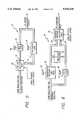
- FIG. 4is a schematic representation of a pressure-limited, time-cycled ventilator with volume-cycle override, in accordance with a preferred embodiment of the present invention
- FIG. 5is a schematic representation of the flow control subsystem employed in the ventilator of FIG. 4;
- FIG. 6is a schematic representation of the pressure reference subsystem employed in the ventilator of FIG. 4;
- FIG. 7is a diagrammatic representation of a hot wire flow sensor head, of the type used in a preferred embodiment of the present invention.
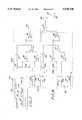
- FIG. 8is a schematic diagram of the electronic circuitry used in the preferred embodiment of the present invention to process the output signal from the flow sensor head of FIG. 7.
- FIGS. 1, 2, and 3The principles of operation of the present invention are best understood with reference first to FIGS. 1, 2, and 3.
- FIG. 1graphically illustrates the method of operation of a typical pressure-limited, time-cycled ventilator.
- the uppermost graph Ais a graph of proximal pressure versus time; the middle graph B is a graph of respiratory flow rate (at the patient connection) versus time; and the lowermost graph C is a graph of the pulmonary tidal volume versus time.
- the time period for the inspiratory phaseis indicated by the notation "INSP. TIME" on the horizontal (time) axis.
- the patient's respiratory (inhalation) flow ratealmost instantaneously reaches a plateau level, substantially equal to the constant flow rate generated by a continuous flow ventilator.
- the proximal pressure(which is a function of tidal volume, pulmonary and patient circuit compliance, and, to a lesser degree, inhalation flow rate and airway resistance) quickly increases to its preselected maximum value, or pressure relief level, indicated in FIG. 1 by the notation "PRESS. RELIEF".
- the proximal pressureis maintained at this pressure relief level by the operation of a pressure relief mechanism, which includes an exhalation valve, as will be described below in conjunction with the description of the apparatus illustrated in FIG. 4.
- the patient's inhalation gas flowcontinues, at a declining flow rate, until the end of the inspiratory time period, at time T 1 .
- the tidal volumeincreases throughout the inspiratory period, the tidal volume at the end of the inspiratory phase ("END TIDAL VOLUME") being chiefly a function of the pressure relief level and the compliance of the patient's lungs, with patient airway resistance, gas flow rate, and the length of the inspiratory time period also being factors.
- the exhalation phaseis commenced by the opening of the exhalation valve, and the proximal pressure rapidly falls either to ambient pressure, or, as shown in FIG. 1, to a preselected positive end expiratory pressure (PEEP).
- PEEPpositive end expiratory pressure
- the gas flowreverses, as shown in graph B, indicating an exhalation flow from the patient through the exhalation valve.
- FIG. 2graphically illustrates the method of operation of a typical volume-cycled ventilator.
- the uppermost graph Dis a graph of proximal pressure versus time;
- the middle graph Eis a graph of respiratory flow rate (at the patient connection) versus time;
- the lowermost graph Fis a graph of the pulmonary tidal volume versus time.
- an inspiratory gas flowis generated by the ventilator.
- the gas flow ratemay be a substantially constant flow rate, as represented by the square wave shown in the graph E, or it may be a decelerating flow rate, an accelerating flow rate, or a sinusoidal flow rate.
- PIPpeak inspiratory pressure
- the tidal volumealso increases substantially linearly.
- a volume-cycled ventilatoroffers a selectable and controllable end tidal volume, but the peak inspiratory pressure may exceed a desired level, unless otherwise limited, for example, by an overpressure relief valve or the like.
- FIG. 3graphically illustrates the method of operation of a pressure-limited, time-cycled ventilator with volume-cycle override, in accordance with the present invention.
- the uppermost graph Gis a graph of proximal pressure versus time
- the middle graph His a graph of respiratory flow rate (at the patient connection) versus time
- the lowermost graph Iis a graph of the pulmonary tidal volume versus time.
- the solid curverepresents the operation of a pressure-limited, time-cycled ventilator with volume-cycle override, in accordance with the present invention
- the dashed-line curverepresents the operation of a conventional pressure-limited, time-cycled ventilator (i.e., without volume-cycle override).
- the dashed-line curvemay represent the operation of a pressure-limited, time-cycled ventilator with volume-cycle override, wherein the volume limit (as will be described below) is not reached during the preselected inspiratory time period.
- a ventilator in accordance with the present inventiongenerates a substantially constant gas flow rate.
- the inspiratory time periodbegins, at a time T 0 , with the patient's inhalation flow rate almost instantaneously reaching a plateau level that is substantially equal to the ventilator's constant flow rate.
- the proximal pressurequickly rises to its preselected pressure relief level, at which it is maintained by the pressure control mechanism, as will be described below.
- the tidal volumealso increases, but, if it reaches a preselected volume limit prior to the end of the preselected inspiratory time period (at the time T 1 ), the inspiratory phase is terminated at an earlier time T VL . This is accomplished by opening the exhalation valve, thereby initiating the expiratory phase and allowing the patient to exhale to ambient or (as shown in the graph G) to a preselected PEEP.
- the ventilatorfunctions as a conventional pressure-limited, time-cycled, ventilator, switching to the expiratory phase at the time T 1 that ends the preselected inspiratory time period.
- FIG. 4A preferred embodiment of a pressure-limited, time-cycled ventilator 10 with volume-cycle override is shown schematically in FIG. 4.
- the ventilator 10has a pressurized oxygen inlet 12 and a pressurized air inlet 14, each of which receives its respective gas from a conventional pressurized source (not shown).
- the air and oxygenare pressure-regulated and blended in selectable proportions in a regulating and blending subsystem 16, of conventional design.
- the blended respiratory gasis then passed through a flow control subsystem 18 (to be described in detail below) that controls the flow rate of the respiratory gas.
- the flow- and pressure-regulated respiratory gasthen is passed from the ventilator 10 into a gas conduit forming a patient circuit having an inspiratory leg 20 and an expiratory leg 22.
- a patient connector 24 at the juncture between the inspiratory leg 20 and the expiratory leg 22provides fluid communication between the airway of a patient 26 and the patient circuit.
- the expiratory leg 22communicates between the patient connector 24 and an exhalation valve 28 in the ventilator 10. The operation of the exhalation valve 28 will be described below.
- the ventilator 10provides a continuous flow rate of gas through the patient circuit during the inspiratory phase, and an equal or lower (but also continuous) "base" flow rate during the expiratory phase.
- inspirationthe patient 26 inhales gas into his or her lungs (not shown) through the patient connector 24.
- exhalationthe patient 26 exhales gas through the patient connector 24, from which the exhaled gas joins with the ventilator-generated base flow in the patient circuit, and this mixture of exhaled gas and base flow gas is conducted by the expiratory leg 22 to the exhalation valve 28.
- the exhalation valve 28includes an inlet 30 that receives gas from the expiratory leg 22, and an outlet vent 32 to the exterior of the ventilator 10. An expiratory flow path is thus defined by the expiratory leg 22 of the patient circuit, the exhalation valve inlet 30, and the exhalation valve outlet vent 32.
- the exhalation valve 28also includes a proximal pressure port 33 that receives the patient's proximal airway pressure from the patient connector 24 through a proximal pressure sensing line 34, and a reference pressure port 35 that receives a reference pressure from a pressure reference subsystem 36, as will be described in detail below.
- a proximal pressure gauge and/or transducer 38is advantageously coupled to the proximal pressure sensing line 34 to provide a visual indication of the proximal pressure.
- the exhalation valve 28is pneumatically servo-actuated, whereby proximal pressure is continuously directed to one side of an internal, differential pressure valving mechanism (not shown), while the reference pressure is directed to the other side.
- the valving mechanismblocks the portion of the expiratory flow path between the exhalation valve inlet 30 and the outlet vent 32 as long as the pressure differential (between the proximal pressure and the reference pressure) indicates that the proximal pressure is less than the reference pressure.
- the valve mechanismresponds by opening the expiratory flow path (typically by opening the outlet vent 32) with the degree of opening being proportional to the magnitude of the pressure differential.
- the opening of the expiratory flow pathcauses the proximal pressure directed to the exhalation valve 28 to fall, whereby the magnitude of the pressure differential across the valving mechanism decreases, thereby causing the degree of opening of the expiratory flow path to decrease proportionately.
- exhalation valve 28is not a part of the present invention, and it may assume a number of functionally satisfactory embodiments. Furthermore, exhalation valves that would operate satisfactorily in the ventilator 10 are well known in the art. Therefore, a detailed description of such a valve is not necessary here.
- the exhalation valve 28includes a first chamber in communication with the proximal pressure port 33, a second chamber in communication with the reference pressure port 35, a pressure-responsive element (such as a diaphragm) separating the two chambers, a valve closure member disposed between the inlet port 30 and the outlet vent 32, and a linkage mechanically connecting the pressure-responsive element with the closure member to provide the proportional opening function described above.
- a pressure-responsive elementsuch as a diaphragm
- the flow sensor head 40Disposed within the patient connector 24 so as to receive the flow of gas therethrough is a flow sensor head 40.
- the flow sensor head 40may be of any suitable type, such as a fixed or variable orifice pneumotachograph, an ultrasonic flow sensor, or a rotary element flow sensor, all of which are well-known in the art.
- the flow sensor head 40is of the hot wire type. Examples of suitable hot wire flow sensors are disclosed in U.S. Pat. Nos. 4,363,238 and 5,263,369, and in co-pending U.S. patent application Ser. No. 08/273,888; filed Jul. 12, 1994; and assigned to the assignee of the present invention.
- the flow sensor head 40is of the type disclosed in the aforementioned U.S. patent application Ser. No. 08/273,888. A detailed description of this type of flow sensor head is set forth below in connection with FIG. 7 of the accompanying drawings.
- the flow sensor head 40generates an analog output signal indicative of the instantaneous gas flow rate through the patient connector 24.
- This flow rate signalwhich has a value indicative of the instantaneous flow rate of gas inhaled and exhaled by the patient through the connector 24, is processed and conditioned by a flow sensor circuit 42.
- Suitable flow sensor circuitsare well-known in the art, as represented, for example, by the aforementioned U.S. Pat. No. 5,263,369. In the preferred embodiment of the present invention, however, the flow sensor circuit 42 is of the type disclosed in the aforementioned U.S. patent application Ser. No. 08/273,888. A detailed description of this circuit is set forth below in connection with FIG. 8 of the accompanying drawings.
- the flow sensor circuit 42when respiratory gas is delivered to the patient, the flow sensor circuit 42 produces a digitized inhalation flow rate signal and outputs it to a volume integration module 44 in a central processing unit (CPU) 46.
- the volume integration module 44is a software module stored in a read only memory (ROM) 47 (FIG. 8) in the CPU 46. It employs a conventional algorithm to integrate the digitized inhalation flow rate signal over specified time intervals to obtain a measured volume value.
- a volume limit control 48 on the ventilator 10is manually operated by the clinician to select a volume limit from a predetermined range.
- the volume limit control 48generates an analog volume limit signal that is fed to a first analog-to-digital converter (ADC) 50 in the CPU 46, which, in turn, digitizes the signal and outputs it to a volume limit setting module 52 in the CPU 46.
- ADCanalog-to-digital converter
- the volume limit setting module 52is a software module that stores the digitized value of the volume limit signal.
- a volume comparator module 54 in the CPU 46periodically reads the measured volume value from the volume integration module 44 and the volume limit value from the volume limit setting module 52, and then electronically compares these two values. The comparison yields a difference signal that is outputted to a breath control module 56 in the CPU 46.
- the breath control module 56is a software module that receives several input signals in addition to the above-mentioned difference signal. Specifically, it receives a breath rate signal, an inspiratory time signal, and an assist trigger signal.
- the breath rate signalis generated by a clinician-operated breath rate control 58 on the ventilator 10, and it is digitized by a second ADC 60 before being inputted to the breath control module 56. Its value represents the selected value of an adjustable breath rate, usually expressed in breaths per minute (BPM).
- the inspiratory time signalis generated by a clinician-operated inspiratory time control 62 on the ventilator 10, and it is digitized by a third ADC 64 before being inputted to the breath control module 56. Its value represents the selected length (duration) of an adjustable inspiratory time period.
- the assist trigger signalis generated by an assist trigger subsystem, which will be described below.
- the breath control moduleincludes an algorithm that reads the values of the aforementioned input signals, and generates a breath control signal that actuates a solenoid control/driver circuit 66.
- the solenoid control/driver circuit 66responds to the breath control signal by generating first and second solenoid actuation signals that respectively actuate solenoid-actuated valves in the flow control subsystem 18 and in the pressure reference subsystem 36, as will be described below.
- FIG. 5illustrates the components and function of the flow control subsystem 18.
- Gas from the regulating and blending subsystem 16is received in the inlet of a solenoid-actuated flow rate selection valve 68.
- the flow rate selection valve 68has two outlets: a first outlet 70 communicates with the inlet of a clinician-adjustable inspiratory flow valve 72, and a second outlet 74 communicates with the inlet of a clinician-adjustable base flow valve 76. Either the first or second outlet of the flow rate selection valve 68 is opened in response to the first solenoid actuation signal generated by the solenoid control/driver circuit 66.
- the value of the first solenoid actuation signalthus determines which of the two flow rate selection valve outlets is opened, thereby determining whether the gas flows through the inspiratory flow valve 72 or the base flow valve 76.
- the first solenoid actuation signalactuates the flow rate selection valve 68 so as to open its first outlet 70 during the inspiratory phase, and its second outlet 74 during the expiratory phase.
- the inspiratory flow valve 72has an outlet that communicates with the inspiratory leg 20 of the patient circuit. This valve provides a substantially constant flow rate of inspiratory gas during the inspiratory phase, which flow rate can be adjusted by the clinician by means of an inspiratory flow rate control 78, which actuates a variable-orifice mechanism (not shown) of conventional design.
- the base flow valve 76likewise has an outlet that communicates with the inspiratory leg 20 of the patient circuit.
- This valvealso provides a substantially constant flow rate of inspiratory gas, but the range of flow rates that it provides is typically equal to or lower than the range of flow rates provided by the inspiratory flow valve 72.
- This "base" flow rateis provided during the expiratory phase to allow the patient (typically an infant or neonate) to take small, spontaneous breaths outside of the preselected inspiratory time period.
- the base flow ratecan be adjusted by the clinician by means of a base flow rate control 80, which actuates a variable orifice mechanism (not shown) of conventional design.
- FIG. 6illustrates the components and function of the pressure reference subsystem 36.
- Gas pressuretypically, the regulated air pressure
- the inspiratory pressure limit valve 82is adjusted by a pressure limit control 86 to select a peak inspiratory pressure (PIP) to be used as a first reference pressure for the actuation of the exhalation valve 28 during the inspiratory phase, thereby (as will be seen) providing the pressure relief function of the ventilator 10.
- PIPpeak inspiratory pressure
- the PEEP adjustment valve 84is adjusted by a PEEP control 88 to select the PEEP value that is used as a second reference pressure for the exhalation valve 28 during the exhalation phase, as will be explained below.
- the selected PEEP reference valuemay typically be varied from zero PEEP (ambient pressure) to a maximum of about 30 cmH 2 O (for an infant ventilator), or higher (for an adult ventilator).
- the adjusted reference pressures from the respective outlets of the inspiratory pressure limit valve 82 and the PEEP adjustment valve 84are communicated to a first inlet 90 and a second inlet 92, respectively, of a solenoid-actuated reference pressure selection valve 94.
- a differential pressure transducer 96is advantageously disposed between the respective outlets of the inspiratory pressure limit valve 82 and the PEEP adjustment valve 84 so as to receive the selected PIP reference pressure on one side of the transducer 96, and the selected PEEP reference pressure on the other side.
- the transducer 96compares the two reference pressures, and generates a warning device actuation signal if the PEEP reference pressure exceeds the PIP reference pressure.
- the warning device actuation signalis employed to actuate a warning device, such as an audible and/or visible alarm (not shown).
- the reference pressure selection valve 94includes an outlet that communicates with the reference pressure port 35 of the exhalation valve 28, and (as mentioned above) the first inlet 90 that receives the PIP reference pressure and the second inlet 92 that receives the PEEP reference pressure.
- the reference pressure selection valve 94responds to the second solenoid actuation signal generated by the solenoid control/driver circuit 66 to open either the first inlet 90 or the second inlet 92.
- the value of the second solenoid actuation signalthus determines which of the reference pressures (PIP reference pressure or PEEP reference pressure) is communicated, through the reference pressure selection valve 94, to the reference pressure port 35 of the exhalation valve 28.
- the hot wire flow sensor head 40of the type employed in the preferred embodiment of the present invention, is shown diagrammatically.
- the flow head 40comprises a tubular housing 112 having an open inlet end 114 and an open outlet end 116.
- a first thermoresistive wire element 118mounted transversely to the direction of gas flow (indicated by the arrow), and a second thermoresistive wire element 120 mounted parallel to the direction of gas flow.
- the first or transverse wire element 118may also be termed the "sensor” element, while the second or parallel wire element 120 may be termed the "reference" element, as will be made clear below.
- the wire elements 118, 120may be supported within the housing 112 on insulative supports 122, with leads (not shown) extending through the housing wall for connection to the circuit to be described below.
- the wire elements 118, 120have identical thermoresistive characteristics, in that the sensing element 118 and the reference element 120 will exhibit the same resistance at any given temperature within a given temperature range. In a zero gas flow condition, the same current flowing through the two elements will result in equal power consumption by the two elements. When gas flows through the flow sensor head 40, however, the transverse sensor element 118 will experience a greater heat loss in response to the gas flow than will the parallel reference element 120 (as will be explained below), thereby lowering its resistance relative to the reference element. Therefore, to maintain the two wire elements at an equal temperature, the current must be increased through the sensor element 118, thereby increasing its power consumption relative to that of the reference element 120.
- the difference in power consumed by the sensor element and the reference element in maintaining the two elements at the same temperatureis thus a function of the flow rate of the gas. Since both elements are located in close proximity to each other and are exposed to the same gaseous medium, variations in gas temperature, composition of the gas mixture, and humidity will have a negligible effect upon the resultant power differential.
- the function of the present inventiontherefore, is to measure this power differential, and then relate it quantitatively to the flow rate of gas through the sensor head 40.
- FIG. 8diagrammatically illustrates a preferred embodiment of the flow sensor circuit 42, from which is obtained an output signal indicative of the volumetric flow rate of gas through the flow sensor head 40.
- the flow sensor circuit 42comprises a pair of ratiometric comparator circuits: a first comparator circuit 132a for the sensor element 118, and a second comparator circuit 132b for the reference element 120.
- the first comparator circuit 132aincludes a first current generator 134 that supplies current to the sensor element 118, thereby heating the sensor element 118.
- a first current sense resistor 136Connected in series between the first current generator 134 and the sensor element 118 is a first current sense resistor 136, which is a fixed resistance of known value.
- the heating currentalso passes through cables and connectors, schematically represented by series resistors 138 and 140.
- a first differential amplifier 142is connected across the first current sense resistor 136, producing a first analog output signal having a voltage value that is related to the heating current supplied to the sensor element 118 by Ohm's Law (and by a known amplification factor).
- Ohm's Lawand by a known amplification factor
- a second differential amplifier 144is connected across the sensor element 118, and produces a second analog output signal having a value that is indicative of the voltage across the sensor element 118. Since the heating current through the sensor element 118 is known (by means of the output signal value from the first amplifier 142, as described above), the value of the output signal of the second amplifier 144 is indicative, via Ohm's Law, of the instantaneous resistance of the sensor element 118. (Additional cable and connector resistances, represented schematically by resistors 146 and 148 in the input leads of the second amplifier 144, may also be present in the circuit.)
- the output signals from both the first amplifier 142 and the second amplifier 144are fed into a third differential amplifier 150, which produces a third output signal having a voltage value that is proportional to the difference in the first and second output signal values.
- This third output signalwhich is advantageously amplified by a fourth amplifier 152, is then fed back as an input to the first current generator 134 as a correction signal to adjust the heating current to a value which minimizes the difference between the first and second output signal values.
- the first comparator circuit 132awill be in balance when the value of the heating current is such as to make the resistance of the sensor element 118 equal to the fixed resistance of the first current sense resistor 136, thereby equalizing the voltage drops across the sensor element 118 and the first current sense resistor 136.
- the power P s delivered to the sensor element 118is also known, by the formula:
- I sis the heating current through the sensor element 118
- R 1is the resistance of the first current sense resistor 136.
- sensor element powermay be expressed as:
- V 1is the voltage value of the first output signal.
- the voltage value of the first output signalwhen squared and divided by the resistance of the first sense resistor 136, provides an accurate measurement of the power delivered to the sensor element 118. Therefore, to obtain the squared value of the first output signal voltage, the first output signal is fed into a first squaring circuit 154, and this squared first output signal value is then inputted to a final differential amplifier 156 for final processing, as described below.
- the cable and connector resistancesare not involved in the calculation of sensor element power P s , and thus do not affect the measurement of this parameter.
- the second comparator circuit 132b for the reference element 120is essentially identical to the first comparator circuit 132a described above.
- the second comparator circuit 132bcomprises a second current generator 158 that supplies heating current to the reference element 120 through a second current sense resistor 160, of known, fixed value, equal to the value of the first current sense resistor.
- a fifth amplifier (differential amplifier) 162is connected across the second current sense resistor 160, producing a fourth analog output signal having a voltage value that is related to the heating current value by Ohm's Law and the amplifier's gain.
- a sixth amplifier (differential amplifier) 164is connected across the reference element 120, and produces a fifth analog output signal having a value that is indicative of the voltage across the reference element 120, and therefore, as explained above in connection with the second amplifier 144 and the sensor element 118, of the instantaneous resistance of the reference element 120.
- cable and connector resistancesare shown schematically by fixed resistors 166, 168, 170, and 172.
- the fourth and fifth output signals from the fifth amplifier 162 and the sixth amplifier, respectively,are fed into a seventh amplifier (differential amplifier) 174, which performs a function analagous to that of the third amplifier 150 of the first comparator circuit 132a: It produces a sixth output signal having a voltage value that is proportional to the difference in the fourth and fifth output signal values.
- This sixth output signalwhich is advantageously amplified by an eighth amplifier 176, is then fed back as an input to the second current generator 158 as a correction signal to adjust the heating current through the reference element 120 to a value that minimizes the difference between the fourth and fifth output signal values.
- the second comparator circuit 132bfunctions in a manner that is essentially identical to the operation of the first comparator circuit 132a.
- the circuit 132bis in balance when the value of the heating current through the reference element 120 is such as to make the resistance of the reference element 120 equal to an equilibrium value which equals the fixed resistance of the second current sense resistor 160, thereby equalizing the voltage drops across the reference element 120 and the second current sense resistor 160. Therefore, the power P r delivered to the reference element 120 can be expressed as:
- I ris the heating current through the reference element 120
- R 2is the resistance of the second current sense resistor 160
- V 4is the voltage value of the fourth output signal.
- the voltage value of the fourth output signalwhen squared and divided by the resistance of the second sense resistor 160, provides an accurate measurement of the power delivered to the reference element 120. Therefore, to obtain the squared value of the fourth output signal voltage, the fourth output signal is fed into a second squaring circuit 178, and this squared fourth output signal value is then inputted to the final differential amplifier 156 for final processing.
- the final differential amplifier 156receives, as inputs, the squared first output signal and the squared fourth output signal, as described above, and compares these squared values to yield a final analog output signal that indicates the difference between the two squared values.
- This differencewhich may be termed ⁇ P, represents the difference in the power respectively delivered to the sensor element 118 and the reference element 120 at any given flow rate of gas through the flow head 40.
- ⁇ Prepresents the difference in the power respectively delivered to the sensor element 118 and the reference element 120 at any given flow rate of gas through the flow head 40.
- the final analog output signalis fed into an analog-to-digital converter (ADC) 180, thereby digitizing the signal for input into the CPU 46.
- ADCanalog-to-digital converter
- the ROM 47 of the CPU 46has stored within it, in the form of a look-up table, the values corresponding to an empirically-derived flow rate-versus-delta power curve.
- the digitized ⁇ P valueis used to address the look-up table, thereby acquiring the corresponding flow rate value, which is then outputted to the volume integration module 44 in the CPU 46.
- the flow rate-versus-delta power curve that is stored in the ROM 47can be empirically-derived for each individual flow sensor head 40 during the manufacturing process by constructing the flow sensor head 40 and the circuit 42, and then causing known flow rates of gas (controlled, for example, by a precision flow control system, of any suitable type known in the art) to flow through the flow sensor head 40.
- the values of ⁇ P corresponding to each desired flow rate value in the selected rangeare then measured (by conventional means) to derive the flow rate-versus-delta power curve.
- the values from this curveare then stored in the ROM 47.
- each flow sensor systemis individually pre-calibrated by the manufacturer prior to clinical usage, thereby eliminating the need for further calibration by the clinician, while also providing precise compensation for variations between individual flow sensing systems, due to, for example, the tolerances in the physical and electrical characteristics of the constituent components.
- the system described aboveis capable of achieving very high degrees of accuracy in flow rate measurement, even at low flow rates. For example, flow rate measurements with an accuracy of 1 per cent can be achieved, even at flow rates as low as 50 ml/min. Such high accuracy at low flow rates makes such a system particularly well-suited for use in mechanical pulmonary ventilation systems, which, like the present invention, is particularly well-adapted for use with neonates.
- the flow sensor head 40may advantageously be adapted for bi-directional flow rate measurements by providing a third thermoresistive wire element 182 that functions as a second sensor element.
- the third wire element 182like the first wire element 118, is mounted transversely in the housing 116, on the opposite side of the parallel wire element 120 from the first wire element 118.
- the third wire elementis connected in a third comparator circuit (not shown) which is essentially identical to the first comparator circuit 132a.
- the third comparator circuit, containing the third wire element 182is employed when gas flow through the housing 116 is in the direction opposite to that indicated by the arrow in FIG. 7.
- Such a bi-directional flow sensormay be preferred in some application.
- the clinicianselects a volume limit with the volume limit control 48; a breath rate with the breath rate control 58; and an inspiratory time period with the inspiratory time control 62.
- the digitized value of the volume limitis stored in the volume limit setting module 52, as previously described, while the digitized values of the breath rate and the inspiratory time period are stored in the breath control module 56, as also described above.
- the breath control module 56sends a breath control signal having a first (inspiration initiation) value to the solenoid control/driver circuit 66.
- the solenoid control/driver circuit 66responds to the inspiration initiation value of the breath control signal by generating the first and second solenoid actuation signals.
- the first solenoid actuation signalis directed to the solenoid of the flow rate selection valve 68 in the flow control subsystem 18.
- This signalhas a first value that causes the flow rate selection valve 68 to open its first outlet 70 (and thus to close its second outlet 74), thereby directing gas from the regulating and blending subsystem 16, through the inspiratory flow valve 72, and into the inspiratory leg 20 of the patient circuit, with the inspiratory flow rate set by the inspiratory flow rate control 74.
- the second solenoid actuation signalis directed to the solenoid of the reference pressure selection valve 94 in the pressure reference subsystem 36.
- This signalhas a first value (not necessarily equal to the first value of the first solenoid actuation signal) that causes the reference pressure selection valve 94 to open its first inlet 90 (and thus to, close its second inlet 92), thereby applying the PIP (set by the inspiratory pressure limit valve 82) as the reference pressure at the reference pressure port 35 of the exhalation valve 28.
- the patient 26receives the selected inspiratory flow rate through the inspiratory leg 20 of the patient circuit and the patient connector 24, and the patient inhales from this flow.
- the patient's airway proximal pressureis communicated from the patient connector 24 to the proximal pressure port 33 of the exhalation valve 28 by the proximal pressure line 34.
- the proximal pressureis less than the PIP reference pressure at the reference pressure port 34, the exhalation valve remains closed, and exhalation is impeded.
- the exhalation valve 28opens the expiratory flow path sufficiently, and for a sufficient time, in the manner described above, to relieve the excess pressure, maintaining the proximal pressure substantially at the limit established by the PIP reference pressure.
- the digitized value of the preselected inspiratory time periodis stored, as previously mentioned, in the breath control module 56.
- a timer (not shown) in the breath control module 56is initiated at time T 0 and clocks the elapsed time. If the timer reaches a value equal to the stored inspiratory time period value, then the preselected inspiratory time period has elapsed without the tidal volume having reached the preselected volume limit.
- the breath control module 56sends a breath control signal having a second (inspiration termination) value to the solenoid control/driver circuit 66.
- the solenoid control/driver circuit 66responds to the inspiration termination value of the breath control module output signal by sending the first and second solenoid actuation signals to the respective solenoids of the flow rate selection valve 68 and the reference pressure selection valve 94.
- the first solenoid actuation signalhas a second value that causes the flow rate selection valve 68 to close its first outlet 70 and open its second outlet 74. Gas from the regulating and blending subsystem 16 is thus directed through the base flow valve 76, allowing only the preselected base flow to flow into inspiratory leg 20 of the patient circuit.
- the second solenoid actuation signalalso has a second value (not necessarily equal to the second value of the first solenoid actuation signal) that causes the reference pressure selection valve 94 to open its second inlet 92 and close its first inlet 90.
- the PEEP reference pressure from the PEEP control valve 84is passed by the reference pressure selection valve 94 to the reference pressure port 35 of the exhalation valve 28.
- the patient 26receives the selected base flow rate through the inspiratory leg 20 of the patient circuit and the patient connector 24.
- the patient's airway proximal pressureis communicated from the patient connector 24 to the proximal pressure port 33 of the exhalation valve 28 by means of the proximal pressure line 34.
- the exhalation valveis opened, allowing expiratory flow through the expiratory flow path, from the expiratory leg 22 of the patient circuit, through the inlet 30 of the exhalation valve 28, and out to ambient through the outlet vent 32 of the exhalation valve 28.
- the patientis permitted to exhale through the open exhalation valve 28, with the exhaled gasses from the patient joining the base flow from the ventilator.
- the proximal pressuredecreases during the expiratory phase, it approaches the PEEP reference pressure, and, as it does so, the exhalation valve 28 begins to close the expiratory flow path (by means of the above-described pneumatic servo operation) to a degree sufficient to maintain the proximal pressure at or above the PEEP reference pressure level.
- the patientexhales to the preselected PEEP reference pressure.
- the PEEP reference pressureis set to zero PEEP, the exhalation valve 28 remains fully open throughout the expiratory phase, and the patient exhales to ambient pressure.
- the volume integration module 44receives a digitized inhalation flow rate signal from the flow sensor circuit 42, and integrates the value of this signal over time to obtain a measured tidal volume value.
- This measured tidal volume valueis compared, in the volume comparison module 54, with the digitized volume limit value generated by the volume limit setting module 52. This comparison yields the above-mentioned difference signal which is inputted to the breath control module 56. If the value of the difference signal indicates that the measured tidal volume is less than the preselected volume limit, then the breath control signal outputted by the breath control module 56 is unaffected.
- the breath control module 56If, on the other hand, the difference signal indicates that the measured tidal volume is equal to or greater than the preselected volume limit, then the breath control module 56 generates a breath control signal having the second (inspiration termination) value, causing the solenoid control/driver circuit 66 to generate its first and second solenoid actuation signals having their respective second values.
- the ventilator 10terminates the inspiratory flow (and shifts to the base flow), and opens the exhalation valve 28 (with the preselected PEEP value as the reference pressure).
- the inspiratory phaseis terminated at the time T VL shown in the graph I of FIG. 3, which is before the end of the preselected inspiratory time period.
- the expiratory phaseis therefore commenced in response to the patient's tidal volume reaching the preselected volume limit, rather than in response to the elapsing of the preselected inspiratory time period.
- the value of the breath rate signal generated by the breath rate control 58is stored in memory (not shown) in the breath control module 56.
- the value of the breath rate signaldefines the time period for the periodic reinitiation of the inspiratory time period; that is, it defines the period of repetition of the inspiratory/respiratory breath cycle described above.
- the ventilatoris returned to the conditions existing at the time T 0 , as described above.
- the ventilator 10is advantageously provided with an assist mode capability, provided by an assist trigger module 98.
- the assist trigger module 98is a software module stored in a ROM (not shown) in the CPU 46. It contains an algorithm for providing a machine-assisted breath to the patient under certain specified conditions.
- the assist trigger module 98receives the digitized inhalation flow rate signal from the flow sensor circuit 42, along with a digitized assist level signal.
- the assist level signalis generated as an analog signal by a clinician-operated assist sensitivity control 100, and this analog signal is digitized by a fourth ADC 102.
- the assist level signalhas a value representing a minimum inhalation flow rate necessary for triggering an assisted breath.
- the digitized assist level signal value and the digitized measured inhalation flow rate valueare compared in the assist trigger module 98. If the measured flow rate value is greater than the assist level signal value, the algorithm in the assist trigger module then determines if the ventilator is in an "assist disabled" period.
- the assist disabled periodcomprises the inspiratory time period, plus a selectable beginning portion of the expiratory time period. Only during the remainder of the expiratory time period can the assist mode be enabled.
- the algorithmnext determines if the assist trigger "window" is open; that is, if the ventilator's operational mode would, at that point in the breath cycle, permit the ventilator to provide a machine-assisted breath. If the "window" is open, the assist trigger module 98 generates an assist trigger output signal that is inputted to the breath control module 56. The breath control module 56, in turn, responds by sending a control signal having the first (inspiration initiation) value to the solenoid control driver circuit 66, which, in turn, responds by generating the first and second solenoid actuation signals having their respective first values, as described above.
- the first and second solenoid actuation signalsactuate the flow rate selection valve 74 to select the inspiratory flow rate, and the reference pressure selection valve 94 to select the PIP reference pressure.
- the result of these actuationsis to cause the ventilator to deliver a machine-assisted breath to the patient.
- the algorithmdetermines if the ventilator is in either a CPAP (Continuous Positive Airway Pressure) or SIMV (Synchronous Intermittent Mandatory Ventilation) mode. If it is in either of these modes, a spontaneous breath count register (not shown) is incremented, but no assist trigger output signal is generated.
- CPAPContinuous Positive Airway Pressure
- SIMVSession Intermittent Mandatory Ventilation
- the ventilator system described abovewill be seen to provide the advantages of a pressure-limited, time-cycled ventilator, with the additional advantages provided by the volume-cycle override feature, of which the most prominent is the effective management of the above-described problems associated with changes in the patient's airway compliance.
- the novel approach of integrating a volume-cycle override function into a pressure-limited, time-cycled ventilatorprovides an easily implemented regimen for controlling the ventilation process so as to compensate automatically for compliance changes in a manner that does not require frequent monitoring or adjustment of the ventilator's operational parameters, thereby facilitating the use of such a ventilator in the clinical environment.
- the present inventionmay be employed in a pressure-limited, time-cycled ventilator that provides the same selected flow rate during both the inspiratory phase and the expiratory phase, rather than having a different base flow rate during the expiratory phase.
- the flow rate sensing system and the exhalation valve system described aboveare exemplary only, and functionally suitable alternatives may suggest themselves.
- the assist mode functionmay be provided by alternatives to the system described above, or even omitted altogether, if desired.
Landscapes
- Health & Medical Sciences (AREA)
- Emergency Medicine (AREA)
- Pulmonology (AREA)
- Engineering & Computer Science (AREA)
- Anesthesiology (AREA)
- Biomedical Technology (AREA)
- Heart & Thoracic Surgery (AREA)
- Hematology (AREA)
- Life Sciences & Earth Sciences (AREA)
- Animal Behavior & Ethology (AREA)
- General Health & Medical Sciences (AREA)
- Public Health (AREA)
- Veterinary Medicine (AREA)
- Measurement Of The Respiration, Hearing Ability, Form, And Blood Characteristics Of Living Organisms (AREA)
Abstract
Description
P.sub.s =I.sub.s.sup.2 R.sub.1 (2);
P.sub.s =V.sub.1.sup.2 /R.sub.1 (2);
P.sub.r =I.sub.r.sup.2 R.sub.2 (3),
P.sub.r =V.sub.4.sup.2 /R.sub.2 (4),
ΔP=V.sub.s.sup.2 /R.sub.1 -V.sub.r.sup.2 /R.sub.2 ; or(5)
ΔP=(V.sub.s.sup.2 -V.sub.r.sup.2)/.sub.R (6)
______________________________________ Power (mw) Flow rate (Liter/min) ______________________________________ 2.1 0.0 26.5 0.1 31.0 0.2 35.3 0.3 38.5 0.4 45.1 0.6 51.4 0.8 61.0 1.2 69.6 1.6 82.4 2.4 94.2 3.2 113.5 4.8 129.5 6.4 154.9 9.6 173.4 12.8 205.0 19.2 229.9 25.6 269.3 38.4 273.0 40.0 ______________________________________
Claims (28)
Priority Applications (1)
| Application Number | Priority Date | Filing Date | Title |
|---|---|---|---|
| US08/351,833US5540220A (en) | 1994-12-08 | 1994-12-08 | Pressure-limited, time-cycled pulmonary ventilation with volume-cycle override |
Applications Claiming Priority (1)
| Application Number | Priority Date | Filing Date | Title |
|---|---|---|---|
| US08/351,833US5540220A (en) | 1994-12-08 | 1994-12-08 | Pressure-limited, time-cycled pulmonary ventilation with volume-cycle override |
Publications (1)
| Publication Number | Publication Date |
|---|---|
| US5540220Atrue US5540220A (en) | 1996-07-30 |
Family
ID=23382608
Family Applications (1)
| Application Number | Title | Priority Date | Filing Date |
|---|---|---|---|
| US08/351,833Expired - LifetimeUS5540220A (en) | 1994-12-08 | 1994-12-08 | Pressure-limited, time-cycled pulmonary ventilation with volume-cycle override |
Country Status (1)
| Country | Link |
|---|---|
| US (1) | US5540220A (en) |
Cited By (149)
| Publication number | Priority date | Publication date | Assignee | Title |
|---|---|---|---|---|
| WO1997010019A1 (en)* | 1995-09-15 | 1997-03-20 | Resmed Limited | Flow estimation and compensation of flow-induced pressure swings in cpap treatment and assisted respiration |
| US5692497A (en)* | 1996-05-16 | 1997-12-02 | Children's Medical Center Corporation | Microprocessor-controlled ventilator system and methods |
| US5706801A (en)* | 1995-07-28 | 1998-01-13 | Caire Inc. | Sensing and communications system for use with oxygen delivery apparatus |
| US5921238A (en)* | 1994-09-12 | 1999-07-13 | Nellcor Puritan Bennett France Developpement | Pressure-controlled breathing aid |
| US5937855A (en)* | 1995-04-21 | 1999-08-17 | Respironics, Inc. | Flow regulating valve in a breathing gas delivery system |
| US6006748A (en) | 1996-10-16 | 1999-12-28 | Resmed Limited | Vent valve apparatus |
| US6029660A (en) | 1996-12-12 | 2000-02-29 | Resmed Limited | Substance delivery apparatus |
| US6029665A (en) | 1993-11-05 | 2000-02-29 | Resmed Limited | Determination of patency of airway |
| USD421298S (en)* | 1998-04-23 | 2000-02-29 | Resmed Limited | Flow generator |
| US6091973A (en) | 1995-04-11 | 2000-07-18 | Resmed Limited | Monitoring the occurrence of apneic and hypopneic arousals |
| US6119686A (en)* | 1996-03-29 | 2000-09-19 | Datex-Ohmeda, Inc. | Apnea detection for medical ventilator |
| US6119723A (en) | 1997-02-14 | 2000-09-19 | Resmed Limited, | Apparatus for varying the flow area of a conduit |
| US6123074A (en)* | 1996-09-03 | 2000-09-26 | Respironics, Inc. | Oxygen mixing in a blower-based ventilator |
| US6123072A (en)* | 1996-09-11 | 2000-09-26 | Downs; John B. | Method and apparatus for breathing during anesthesia |
| US6152129A (en) | 1996-08-14 | 2000-11-28 | Resmed Limited | Determination of leak and respiratory airflow |
| EP1068875A2 (en) | 1999-07-15 | 2001-01-17 | Siemens-Elema AB | A method for controlling an expiratory valve in a ventilator |
| US6182657B1 (en) | 1995-09-18 | 2001-02-06 | Resmed Limited | Pressure control in CPAP treatment or assisted respiration |
| US6213119B1 (en)* | 1995-10-23 | 2001-04-10 | Resmed Limited | Inspiratory duration in CPAP or assisted respiration treatment |
| US6216702B1 (en)* | 1994-12-14 | 2001-04-17 | Camtech As | Internal registration of gas/air—and other fluid flows in a human body and use of pressure sensors for such registration |
| US6237593B1 (en) | 1993-12-03 | 2001-05-29 | Resmed Limited | Estimation of flow and detection of breathing CPAP treatment |
| US6237592B1 (en) | 1995-07-03 | 2001-05-29 | Resmed Limited | Auto-calibration of pressure transducer offset |
| US6240921B1 (en) | 1993-12-01 | 2001-06-05 | Resmed, Ltd. | Automated stop/start control in the administration of CPAP treatment |
| US6253764B1 (en) | 1996-05-08 | 2001-07-03 | Resmed, Ltd. | Control of delivery pressure in CPAP treatment or assisted respiration |
| US6258039B1 (en)* | 1998-01-19 | 2001-07-10 | Nippon Sanso Corporation | Respiratory gas consumption monitoring device and monitoring method |
| FR2808207A1 (en)* | 2000-04-28 | 2001-11-02 | Hemocare | Respirator test system has flow sensors is suitable for home use |
| US6336454B1 (en) | 1997-05-16 | 2002-01-08 | Resmed Limited | Nasal ventilation as a treatment for stroke |
| US6367474B1 (en)* | 1997-11-07 | 2002-04-09 | Resmed Limited | Administration of CPAP treatment pressure in presence of APNEA |
| US6397841B1 (en) | 1997-06-18 | 2002-06-04 | Resmed Limited | Apparatus for supplying breathable gas |
| US6439229B1 (en)* | 2000-08-08 | 2002-08-27 | Newport Medical Instruments, Inc. | Pressure support ventilation control system and method |
| WO2002033269A3 (en)* | 2000-10-18 | 2002-10-03 | Oxygen Lifeline Llc | Personal gas supply delivery system |
| US6532957B2 (en) | 1996-09-23 | 2003-03-18 | Resmed Limited | Assisted ventilation to match patient respiratory need |
| US6553992B1 (en)* | 2000-03-03 | 2003-04-29 | Resmed Ltd. | Adjustment of ventilator pressure-time profile to balance comfort and effectiveness |
| US6581598B1 (en)* | 1999-11-24 | 2003-06-24 | Dhd Healthcare Corporation | Positive expiratory pressure device |
| US6584977B1 (en) | 2000-04-06 | 2003-07-01 | Respironics, Inc. | Combined patient interface and exhaust assembly |
| US6644311B1 (en)* | 2001-02-21 | 2003-11-11 | Respironics, Inc. | Monitoring fluid flow in a pressure support system |
| US20030225339A1 (en)* | 2002-05-06 | 2003-12-04 | Respironics Novametrix | Methods for inducing temporary changes in ventilation for estimation of hemodynamic performance |
| US20030234017A1 (en)* | 1999-11-24 | 2003-12-25 | Dhd Healthcare Corporation | Positive expiratory pressure device with bypass |
| EP1374940A2 (en) | 1997-06-17 | 2004-01-02 | Fisher & Paykel Healthcare Limited | Respiratory humidification system |
| US20040123866A1 (en)* | 1993-11-05 | 2004-07-01 | Michael Berthon-Jones | Determination of patency of the airway |
| US6776159B2 (en) | 1999-11-24 | 2004-08-17 | Dhd Healthcare Corporation | Positive expiratory pressure device with bypass |
| US20050133033A1 (en)* | 2003-12-20 | 2005-06-23 | Drager Medical Ag & Co. | Device and process for metering breathing gas |
| US20050139212A1 (en)* | 1994-09-12 | 2005-06-30 | Nellcor Puritan Bennett France Developpement | Pressure-controlled breathing aid |
| US20060037616A1 (en)* | 2004-08-17 | 2006-02-23 | Drager Medical Ag & Co. Kgaa | Process for the automatic recording of pressure-vs.-volume curves during artificial respiration |
| US20060048781A1 (en)* | 2002-12-17 | 2006-03-09 | Hideo Nawata | Oxygen supply apparatus |
| US20060130835A1 (en)* | 2003-09-03 | 2006-06-22 | Ric Investments, Llc | Pressure support system and method |
| US20060272642A1 (en)* | 2003-03-24 | 2006-12-07 | Philippe Chalvignac | Breathing assistance apparatus |
| US7302950B2 (en) | 1991-12-20 | 2007-12-04 | Resmed Limited | Patient interface for respiratory apparatus |
| US20080011300A1 (en)* | 2003-07-29 | 2008-01-17 | Claude Andreiux | System And Process For Supplying Respiratory Gas Under Pressure Or Volumetrically |
| US20080168989A1 (en)* | 2004-11-11 | 2008-07-17 | Goran Cewers | Expiratory Pressure Regulation in a Ventilator |
| US20080230062A1 (en)* | 2007-03-23 | 2008-09-25 | General Electric Company | Setting expiratory time in mandatory mechanical ventilation based on a deviation from a stable condition of exhaled gas volumes |
| US20080295837A1 (en)* | 2007-05-29 | 2008-12-04 | Mccormick Timothy P | Method to limit leak compensation based on a breathing circuit leak alarm |
| US20080302363A1 (en)* | 2007-06-05 | 2008-12-11 | Allied Healthcare Products, Inc. | Ventilator apparatus |
| US20090020119A1 (en)* | 2007-07-19 | 2009-01-22 | Drager Medical Ag & Co. Kg | Respirator and a process for operating a respirator |
| US20090165795A1 (en)* | 2007-12-31 | 2009-07-02 | Nellcor Puritan Bennett Llc | Method and apparatus for respiratory therapy |
| US20090241957A1 (en)* | 2008-03-27 | 2009-10-01 | Nellcor Puritan Bennett Llc | Breathing assistance systems with lung recruitment maneuvers |
| US20100069761A1 (en)* | 2008-09-17 | 2010-03-18 | Nellcor Puritan Bennett Llc | Method For Determining Hemodynamic Effects Of Positive Pressure Ventilation |
| US20100101573A1 (en)* | 2008-10-28 | 2010-04-29 | Foley Martin P | Oscillating positive expiratory pressure device |
| WO2010141983A1 (en)* | 2009-06-09 | 2010-12-16 | Resmed Paris Sas | Breathing assistance device with linear actuated gas regulating valve |
| CN101337101B (en)* | 2007-07-06 | 2011-04-20 | 深圳迈瑞生物医疗电子股份有限公司 | Aerating system of anesthesia apparatus and respirator and pressure monitoring method |
| CN102114284A (en)* | 2009-12-31 | 2011-07-06 | 北京谊安医疗系统股份有限公司 | Inhaling holding method for electrically powered electrically controlled ventilator |
| CN102114288A (en)* | 2009-12-31 | 2011-07-06 | 北京谊安医疗系统股份有限公司 | Tidal volume control method |
| WO2012000096A1 (en)* | 2010-06-30 | 2012-01-05 | St. Michael's Hospital | Method and system for patient-synchronized ventilatory assist with endotracheal through-flow |
| USD653749S1 (en) | 2010-04-27 | 2012-02-07 | Nellcor Puritan Bennett Llc | Exhalation module filter body |
| USD655405S1 (en) | 2010-04-27 | 2012-03-06 | Nellcor Puritan Bennett Llc | Filter and valve body for an exhalation module |
| USD655809S1 (en) | 2010-04-27 | 2012-03-13 | Nellcor Puritan Bennett Llc | Valve body with integral flow meter for an exhalation module |
| CN102500023A (en)* | 2011-12-01 | 2012-06-20 | 于邦仲 | Air source air channel system of breathing machine |
| US8267085B2 (en) | 2009-03-20 | 2012-09-18 | Nellcor Puritan Bennett Llc | Leak-compensated proportional assist ventilation |
| US8272379B2 (en) | 2008-03-31 | 2012-09-25 | Nellcor Puritan Bennett, Llc | Leak-compensated flow triggering and cycling in medical ventilators |
| US8302602B2 (en) | 2008-09-30 | 2012-11-06 | Nellcor Puritan Bennett Llc | Breathing assistance system with multiple pressure sensors |
| US8418691B2 (en) | 2009-03-20 | 2013-04-16 | Covidien Lp | Leak-compensated pressure regulated volume control ventilation |
| US8424521B2 (en) | 2009-02-27 | 2013-04-23 | Covidien Lp | Leak-compensated respiratory mechanics estimation in medical ventilators |
| US8434479B2 (en) | 2009-02-27 | 2013-05-07 | Covidien Lp | Flow rate compensation for transient thermal response of hot-wire anemometers |
| US8439037B2 (en) | 2009-12-01 | 2013-05-14 | Covidien Lp | Exhalation valve assembly with integrated filter and flow sensor |
| US8439036B2 (en) | 2009-12-01 | 2013-05-14 | Covidien Lp | Exhalation valve assembly with integral flow sensor |
| US8457706B2 (en) | 2008-05-16 | 2013-06-04 | Covidien Lp | Estimation of a physiological parameter using a neural network |
| US8469031B2 (en) | 2009-12-01 | 2013-06-25 | Covidien Lp | Exhalation valve assembly with integrated filter |
| US8469030B2 (en) | 2009-12-01 | 2013-06-25 | Covidien Lp | Exhalation valve assembly with selectable contagious/non-contagious latch |
| US8485184B2 (en) | 2008-06-06 | 2013-07-16 | Covidien Lp | Systems and methods for monitoring and displaying respiratory information |
| US8485179B1 (en) | 2009-02-23 | 2013-07-16 | Trudell Medical International | Oscillating positive expiratory pressure device |
| US8539951B1 (en) | 2008-05-27 | 2013-09-24 | Trudell Medical International | Oscillating positive respiratory pressure device |
| EP2644220A1 (en)* | 2012-03-28 | 2013-10-02 | Weinmann Geräte für Medizin GmbH & Co. KG | Method and device for performing hyper-insufflations |
| US8554298B2 (en) | 2010-09-21 | 2013-10-08 | Cividien LP | Medical ventilator with integrated oximeter data |
| USD692556S1 (en) | 2013-03-08 | 2013-10-29 | Covidien Lp | Expiratory filter body of an exhalation module |
| USD693001S1 (en) | 2013-03-08 | 2013-11-05 | Covidien Lp | Neonate expiratory filter assembly of an exhalation module |
| US20140000606A1 (en)* | 2012-07-02 | 2014-01-02 | Nellcor Puritan Bennett Llc | Methods and systems for mimicking fluctuations in delivered flow and/or pressure during ventilation |
| US8676285B2 (en) | 2010-07-28 | 2014-03-18 | Covidien Lp | Methods for validating patient identity |
| USD701601S1 (en) | 2013-03-08 | 2014-03-25 | Covidien Lp | Condensate vial of an exhalation module |
| US8714154B2 (en) | 2011-03-30 | 2014-05-06 | Covidien Lp | Systems and methods for automatic adjustment of ventilator settings |
| US8746248B2 (en) | 2008-03-31 | 2014-06-10 | Covidien Lp | Determination of patient circuit disconnect in leak-compensated ventilatory support |
| US8776792B2 (en) | 2011-04-29 | 2014-07-15 | Covidien Lp | Methods and systems for volume-targeted minimum pressure-control ventilation |
| US8783250B2 (en) | 2011-02-27 | 2014-07-22 | Covidien Lp | Methods and systems for transitory ventilation support |
| US8789529B2 (en) | 2009-08-20 | 2014-07-29 | Covidien Lp | Method for ventilation |
| US8844537B1 (en) | 2010-10-13 | 2014-09-30 | Michael T. Abramson | System and method for alleviating sleep apnea |
| US8844526B2 (en) | 2012-03-30 | 2014-09-30 | Covidien Lp | Methods and systems for triggering with unknown base flow |
| CN104203320A (en)* | 2012-03-21 | 2014-12-10 | 皇家飞利浦有限公司 | Systems and methods for controlling insufflation pressure during insufflation |
| US20150068528A1 (en)* | 2013-09-10 | 2015-03-12 | Breathe Technologies, Inc. | Continuous positive airway pressure therapy target pressure comfort signature |
| US9022031B2 (en) | 2012-01-31 | 2015-05-05 | Covidien Lp | Using estimated carinal pressure for feedback control of carinal pressure during ventilation |
| USD731048S1 (en) | 2013-03-08 | 2015-06-02 | Covidien Lp | EVQ diaphragm of an exhalation module |
| USD731050S1 (en) | 2011-06-06 | 2015-06-02 | Trudell Medical International | Oscillating positive expiratory pressure device |
| USD731065S1 (en) | 2013-03-08 | 2015-06-02 | Covidien Lp | EVQ pressure sensor filter of an exhalation module |
| USD731049S1 (en) | 2013-03-05 | 2015-06-02 | Covidien Lp | EVQ housing of an exhalation module |
| US9089657B2 (en) | 2011-10-31 | 2015-07-28 | Covidien Lp | Methods and systems for gating user initiated increases in oxygen concentration during ventilation |
| USD736905S1 (en) | 2013-03-08 | 2015-08-18 | Covidien Lp | Exhalation module EVQ housing |
| US9144658B2 (en) | 2012-04-30 | 2015-09-29 | Covidien Lp | Minimizing imposed expiratory resistance of mechanical ventilator by optimizing exhalation valve control |
| US9149589B2 (en) | 2009-02-23 | 2015-10-06 | Trudell Medical International | Method and device for performing orientation dependent oscillating positive expiratory pressure therapy |
| US9180266B1 (en)* | 2003-07-17 | 2015-11-10 | Zoll Medical Corporation | Automatic patient ventilator system and method |
| USD744095S1 (en) | 2013-03-08 | 2015-11-24 | Covidien Lp | Exhalation module EVQ internal flow sensor |
| US9364624B2 (en) | 2011-12-07 | 2016-06-14 | Covidien Lp | Methods and systems for adaptive base flow |
| US20160199253A1 (en)* | 2012-11-30 | 2016-07-14 | Christopher A. Di Capua | Automated ventilator with assisted compressions |
| US9492629B2 (en) | 2013-02-14 | 2016-11-15 | Covidien Lp | Methods and systems for ventilation with unknown exhalation flow and exhalation pressure |
| US9498589B2 (en) | 2011-12-31 | 2016-11-22 | Covidien Lp | Methods and systems for adaptive base flow and leak compensation |
| US9517315B2 (en) | 2012-11-30 | 2016-12-13 | Trudell Medical International | Oscillating positive expiratory pressure device |
| USD775345S1 (en) | 2015-04-10 | 2016-12-27 | Covidien Lp | Ventilator console |
| USD778429S1 (en) | 2015-09-02 | 2017-02-07 | Trudell Medical International | Respiratory treatment device |
| USD780906S1 (en) | 2015-09-02 | 2017-03-07 | Trudell Medical International | Respiratory treatment device |
| US9629971B2 (en) | 2011-04-29 | 2017-04-25 | Covidien Lp | Methods and systems for exhalation control and trajectory optimization |
| US9675771B2 (en) | 2013-10-18 | 2017-06-13 | Covidien Lp | Methods and systems for leak estimation |
| US20170273597A1 (en)* | 2016-03-24 | 2017-09-28 | Eresearchtechnology, Inc. | Methods and systems for collecting spirometry data |
| US9808591B2 (en) | 2014-08-15 | 2017-11-07 | Covidien Lp | Methods and systems for breath delivery synchronization |
| US9849257B2 (en) | 2013-08-22 | 2017-12-26 | Trudell Medical International | Oscillating positive respiratory pressure device |
| US9925346B2 (en) | 2015-01-20 | 2018-03-27 | Covidien Lp | Systems and methods for ventilation with unknown exhalation flow |
| US9950129B2 (en) | 2014-10-27 | 2018-04-24 | Covidien Lp | Ventilation triggering using change-point detection |
| US9950135B2 (en) | 2013-03-15 | 2018-04-24 | Covidien Lp | Maintaining an exhalation valve sensor assembly |
| US9956371B2 (en) | 2015-03-24 | 2018-05-01 | Ventec Life Systems, Inc. | Ventilator with integrated cough-assist |
| US9981096B2 (en) | 2013-03-13 | 2018-05-29 | Covidien Lp | Methods and systems for triggering with unknown inspiratory flow |
| US9993604B2 (en) | 2012-04-27 | 2018-06-12 | Covidien Lp | Methods and systems for an optimized proportional assist ventilation |
| US10004872B1 (en) | 2015-03-06 | 2018-06-26 | D R Burton Healthcare, Llc | Positive expiratory pressure device having an oscillating valve |
| US10137274B2 (en) | 2001-11-20 | 2018-11-27 | Fisher & Paykel Healthcare Limited | Patient interfaces |
| US10207069B2 (en) | 2008-03-31 | 2019-02-19 | Covidien Lp | System and method for determining ventilator leakage during stable periods within a breath |
| US10272224B2 (en) | 2013-07-12 | 2019-04-30 | Trudell Medical International | Huff cough simulation device |
| US10362967B2 (en) | 2012-07-09 | 2019-07-30 | Covidien Lp | Systems and methods for missed breath detection and indication |
| US10363383B2 (en) | 2014-02-07 | 2019-07-30 | Trudell Medical International | Pressure indicator for an oscillating positive expiratory pressure device |
| US10449324B2 (en) | 2015-07-30 | 2019-10-22 | Trudell Medical International | Combined respiratory muscle training and oscillating positive expiratory pressure device |
| US10661037B2 (en)* | 2013-06-25 | 2020-05-26 | Socpra Sciences Et Génie S.E.C. | Indirect measurement in a total liquid ventilation system |
| US10773049B2 (en) | 2016-06-21 | 2020-09-15 | Ventec Life Systems, Inc. | Cough-assist systems with humidifier bypass |
| US10857317B2 (en) | 2015-12-04 | 2020-12-08 | Trudell Medical International | Huff cough simulation device |
| US10953278B2 (en) | 2018-02-02 | 2021-03-23 | Trudell Medical International | Oscillating positive expiratory pressure device |
| US20210213217A1 (en)* | 2018-08-21 | 2021-07-15 | Shenzhen Mindray Bio-Medical Electronics Co., Ltd. | Airway anomaly recognition method, ventilation device, and storage medium |
| US11191915B2 (en) | 2018-05-13 | 2021-12-07 | Ventec Life Systems, Inc. | Portable medical ventilator system using portable oxygen concentrators |
| US11247015B2 (en) | 2015-03-24 | 2022-02-15 | Ventec Life Systems, Inc. | Ventilator with integrated oxygen production |
| US11324954B2 (en) | 2019-06-28 | 2022-05-10 | Covidien Lp | Achieving smooth breathing by modified bilateral phrenic nerve pacing |
| CN115177826A (en)* | 2021-04-01 | 2022-10-14 | 康泰医学系统(秦皇岛)股份有限公司 | Mesh atomizer |
| US11478594B2 (en) | 2018-05-14 | 2022-10-25 | Covidien Lp | Systems and methods for respiratory effort detection utilizing signal distortion |
| US11559723B2 (en) | 2017-05-03 | 2023-01-24 | Trudell Medical International | Combined oscillating positive expiratory pressure therapy and Huff Cough simulation device |
| US11752287B2 (en) | 2018-10-03 | 2023-09-12 | Covidien Lp | Systems and methods for automatic cycling or cycling detection |
| US11896767B2 (en) | 2020-03-20 | 2024-02-13 | Covidien Lp | Model-driven system integration in medical ventilators |
| CN119075103A (en)* | 2024-08-05 | 2024-12-06 | 深圳市科曼医疗设备有限公司 | A method, device, system and medium for calculating tidal volume of a ventilator |
| US12257437B2 (en) | 2020-09-30 | 2025-03-25 | Covidien Lp | Intravenous phrenic nerve stimulation lead |
| US12440634B2 (en) | 2021-12-21 | 2025-10-14 | Ventec Life Systems, Inc. | Ventilator systems with integrated oxygen delivery, and associated devices and methods |
Citations (14)
| Publication number | Priority date | Publication date | Assignee | Title |
|---|---|---|---|---|
| US3523527A (en)* | 1966-02-24 | 1970-08-11 | Watson W & Sons Ltd | Electronically controlled variable mode respirator |
| US3633576A (en)* | 1969-10-24 | 1972-01-11 | Bourns Inc | Volumetric respirator |
| US3729000A (en)* | 1971-05-18 | 1973-04-24 | Puritan Bennett Corp | Compliance compensated ventilation system |
| US3916890A (en)* | 1972-11-04 | 1975-11-04 | H G East & Company Limited | Autovent field ventilator |
| US3961627A (en)* | 1973-09-07 | 1976-06-08 | Hoffmann-La Roche Inc. | Automatic regulation of respirators |
| US3972327A (en)* | 1973-03-22 | 1976-08-03 | Hoffmann-La Roche Inc. | Respirator |
| US4057059A (en)* | 1975-07-29 | 1977-11-08 | Oklahoma State University | Intermittent positive pressure breathing device |
| USRE29778E (en)* | 1974-06-07 | 1978-09-26 | Bio-Med Devices, Inc. | Pediatric respirator |
| US4227519A (en)* | 1977-08-06 | 1980-10-14 | Dragerwerk Aktiengesellschaft | Respirator for emergency air supply to a patient |
| US4351344A (en)* | 1980-11-13 | 1982-09-28 | Bio-Med Devices, Inc. | Method and apparatus for monitoring lung compliance |
| US4527557A (en)* | 1984-11-01 | 1985-07-09 | Bear Medical Systems, Inc. | Medical ventilator system |
| US5069220A (en)* | 1989-05-26 | 1991-12-03 | Bear Medical Systems, Inc. | Measurement of gas concentration in exhaled breath |
| US5107831A (en)* | 1989-06-19 | 1992-04-28 | Bear Medical Systems, Inc. | Ventilator control system using sensed inspiratory flow rate |
| US5129390A (en)* | 1987-12-18 | 1992-07-14 | Institut Nationale De La Sante Et De La Recherche Medicale | Process for regulating an artificial ventilation device and such device |
- 1994
- 1994-12-08USUS08/351,833patent/US5540220A/ennot_activeExpired - Lifetime
Patent Citations (14)
| Publication number | Priority date | Publication date | Assignee | Title |
|---|---|---|---|---|
| US3523527A (en)* | 1966-02-24 | 1970-08-11 | Watson W & Sons Ltd | Electronically controlled variable mode respirator |
| US3633576A (en)* | 1969-10-24 | 1972-01-11 | Bourns Inc | Volumetric respirator |
| US3729000A (en)* | 1971-05-18 | 1973-04-24 | Puritan Bennett Corp | Compliance compensated ventilation system |
| US3916890A (en)* | 1972-11-04 | 1975-11-04 | H G East & Company Limited | Autovent field ventilator |
| US3972327A (en)* | 1973-03-22 | 1976-08-03 | Hoffmann-La Roche Inc. | Respirator |
| US3961627A (en)* | 1973-09-07 | 1976-06-08 | Hoffmann-La Roche Inc. | Automatic regulation of respirators |
| USRE29778E (en)* | 1974-06-07 | 1978-09-26 | Bio-Med Devices, Inc. | Pediatric respirator |
| US4057059A (en)* | 1975-07-29 | 1977-11-08 | Oklahoma State University | Intermittent positive pressure breathing device |
| US4227519A (en)* | 1977-08-06 | 1980-10-14 | Dragerwerk Aktiengesellschaft | Respirator for emergency air supply to a patient |
| US4351344A (en)* | 1980-11-13 | 1982-09-28 | Bio-Med Devices, Inc. | Method and apparatus for monitoring lung compliance |
| US4527557A (en)* | 1984-11-01 | 1985-07-09 | Bear Medical Systems, Inc. | Medical ventilator system |
| US5129390A (en)* | 1987-12-18 | 1992-07-14 | Institut Nationale De La Sante Et De La Recherche Medicale | Process for regulating an artificial ventilation device and such device |
| US5069220A (en)* | 1989-05-26 | 1991-12-03 | Bear Medical Systems, Inc. | Measurement of gas concentration in exhaled breath |
| US5107831A (en)* | 1989-06-19 | 1992-04-28 | Bear Medical Systems, Inc. | Ventilator control system using sensed inspiratory flow rate |
Non-Patent Citations (3)
| Title |
|---|
| Brochure, The Bear Cub Enhancement Module: It synchronizes ventilation for less work in breathing, 1994.* |
| Depuis, Y., "Ventilators: Theory and Clinical Application," (C. V. Mosby Co., N.Y., 1986) pp. 126-140 and 513-522. |
| Depuis, Y., Ventilators: Theory and Clinical Application, (C. V. Mosby Co., N.Y., 1986) pp. 126 140 and 513 522.* |
Cited By (317)
| Publication number | Priority date | Publication date | Assignee | Title |
|---|---|---|---|---|
| US7931023B2 (en) | 1991-12-20 | 2011-04-26 | Resmed Limited | Patient interface assembly for CPAP respiratory apparatus |
| US7302950B2 (en) | 1991-12-20 | 2007-12-04 | Resmed Limited | Patient interface for respiratory apparatus |
| US7730886B2 (en) | 1993-11-05 | 2010-06-08 | Resmed Limited | Determination of patency of the airway |
| US20100242965A1 (en)* | 1993-11-05 | 2010-09-30 | Michael Berthon-Jones | Distinguishing between closed and open airway apneas and treating patients accordingly |
| US8381722B2 (en) | 1993-11-05 | 2013-02-26 | Resmed Limited | Distinguishing between closed and open airway apneas and treating patients accordingly |
| US20080163873A1 (en)* | 1993-11-05 | 2008-07-10 | Michael Berthon-Jones | Determination of patency of the airway |
| US8360060B2 (en) | 1993-11-05 | 2013-01-29 | Resmed Limited | Distinguishing between closed and open airway apneas and treating patients accordingly |
| US6029665A (en) | 1993-11-05 | 2000-02-29 | Resmed Limited | Determination of patency of airway |
| US8752547B2 (en) | 1993-11-05 | 2014-06-17 | Resmed Limited | Distinguishing between closed and open airway apneas and treating patients accordingly |
| US20040123866A1 (en)* | 1993-11-05 | 2004-07-01 | Michael Berthon-Jones | Determination of patency of the airway |
| US6138675A (en) | 1993-11-05 | 2000-10-31 | Resmed Ltd. | Determination of the occurrence of an apnea |
| US7320320B2 (en) | 1993-11-05 | 2008-01-22 | Resmed Limited | Determination of patency of the airway |
| US20110011402A1 (en)* | 1993-11-05 | 2011-01-20 | Michael Berthon-Jones | Distinguishing between closed and open airway apneas and treating patients accordingly |
| US6240921B1 (en) | 1993-12-01 | 2001-06-05 | Resmed, Ltd. | Automated stop/start control in the administration of CPAP treatment |
| US6237593B1 (en) | 1993-12-03 | 2001-05-29 | Resmed Limited | Estimation of flow and detection of breathing CPAP treatment |
| US5921238A (en)* | 1994-09-12 | 1999-07-13 | Nellcor Puritan Bennett France Developpement | Pressure-controlled breathing aid |
| US8573206B2 (en) | 1994-09-12 | 2013-11-05 | Covidien Lp | Pressure-controlled breathing aid |
| US20100024820A1 (en)* | 1994-09-12 | 2010-02-04 | Guy Bourdon | Pressure-Controlled Breathing Aid |
| US20050139212A1 (en)* | 1994-09-12 | 2005-06-30 | Nellcor Puritan Bennett France Developpement | Pressure-controlled breathing aid |
| US6216702B1 (en)* | 1994-12-14 | 2001-04-17 | Camtech As | Internal registration of gas/air—and other fluid flows in a human body and use of pressure sensors for such registration |
| US6363270B1 (en) | 1995-04-11 | 2002-03-26 | Resmed Limited | Monitoring the occurrence of apneic and hypopneic arousals |
| US6091973A (en) | 1995-04-11 | 2000-07-18 | Resmed Limited | Monitoring the occurrence of apneic and hypopneic arousals |
| US5937855A (en)* | 1995-04-21 | 1999-08-17 | Respironics, Inc. | Flow regulating valve in a breathing gas delivery system |
| US6237592B1 (en) | 1995-07-03 | 2001-05-29 | Resmed Limited | Auto-calibration of pressure transducer offset |
| US5706801A (en)* | 1995-07-28 | 1998-01-13 | Caire Inc. | Sensing and communications system for use with oxygen delivery apparatus |
| US6332463B1 (en) | 1995-09-15 | 2001-12-25 | Resmed Limited | Flow estimation and compensation of flow-induced pressure swings in CPAP treatment and assisted respiration |
| WO1997010019A1 (en)* | 1995-09-15 | 1997-03-20 | Resmed Limited | Flow estimation and compensation of flow-induced pressure swings in cpap treatment and assisted respiration |
| US6182657B1 (en) | 1995-09-18 | 2001-02-06 | Resmed Limited | Pressure control in CPAP treatment or assisted respiration |
| US6526974B1 (en) | 1995-09-18 | 2003-03-04 | John William Ernest Brydon | Pressure control in CPAP treatment or assisted respiration |
| US6213119B1 (en)* | 1995-10-23 | 2001-04-10 | Resmed Limited | Inspiratory duration in CPAP or assisted respiration treatment |
| US6119686A (en)* | 1996-03-29 | 2000-09-19 | Datex-Ohmeda, Inc. | Apnea detection for medical ventilator |
| US6253764B1 (en) | 1996-05-08 | 2001-07-03 | Resmed, Ltd. | Control of delivery pressure in CPAP treatment or assisted respiration |
| US5692497A (en)* | 1996-05-16 | 1997-12-02 | Children's Medical Center Corporation | Microprocessor-controlled ventilator system and methods |
| US6152129A (en) | 1996-08-14 | 2000-11-28 | Resmed Limited | Determination of leak and respiratory airflow |
| US6279569B1 (en) | 1996-08-14 | 2001-08-28 | Resmed Limited | Determination of leak and respiratory airflow |
| US6123074A (en)* | 1996-09-03 | 2000-09-26 | Respironics, Inc. | Oxygen mixing in a blower-based ventilator |
| US6123072A (en)* | 1996-09-11 | 2000-09-26 | Downs; John B. | Method and apparatus for breathing during anesthesia |
| US8733351B2 (en) | 1996-09-23 | 2014-05-27 | Resmed Limited | Method and apparatus for providing ventilatory assistance |
| US6810876B2 (en) | 1996-09-23 | 2004-11-02 | Resmed Ltd. | Assisted ventilation to match patient respiratory need |
| US7137389B2 (en) | 1996-09-23 | 2006-11-21 | Resmed Limited | Method and apparatus for determining instantaneous inspired volume of a subject during ventilatory assistance |
| US7644713B2 (en) | 1996-09-23 | 2010-01-12 | Resmed Limited | Method and apparatus for determining instantaneous leak during ventilatory assistance |
| US9974911B2 (en) | 1996-09-23 | 2018-05-22 | Resmed Limited | Method and apparatus for providing ventilatory assistance |
| US8051853B2 (en) | 1996-09-23 | 2011-11-08 | Resmed Limited | Method and apparatus for providing ventilatory assistance |
| US6532957B2 (en) | 1996-09-23 | 2003-03-18 | Resmed Limited | Assisted ventilation to match patient respiratory need |
| US6688307B2 (en) | 1996-09-23 | 2004-02-10 | Resmed Limited | Methods and apparatus for determining instantaneous elastic recoil and assistance pressure during ventilatory support |
| US8997739B2 (en) | 1996-10-16 | 2015-04-07 | Resmed Limited | Vent valve apparatus |
| US6889692B2 (en) | 1996-10-16 | 2005-05-10 | Resmed Limited | Vent valve assembly |
| US6006748A (en) | 1996-10-16 | 1999-12-28 | Resmed Limited | Vent valve apparatus |
| US7059325B2 (en) | 1996-10-16 | 2006-06-13 | Resmed Limited | Vent assembly |
| US9770571B2 (en) | 1996-10-16 | 2017-09-26 | Resmed Limited | Vent valve assembly |
| US20060021620A1 (en)* | 1996-12-12 | 2006-02-02 | Resmed Limited | Method and apparatus for substance delivery in system for supplying breathable gas |
| US7779834B2 (en)* | 1996-12-12 | 2010-08-24 | Resmed Limited | Method and apparatus for substance delivery in system for supplying breathable gas |
| US6029660A (en) | 1996-12-12 | 2000-02-29 | Resmed Limited | Substance delivery apparatus |
| US20100282251A1 (en)* | 1996-12-12 | 2010-11-11 | Resmed Limited | Method and apparatus for substance delivery in system for supplying breathable gas |
| US6990977B1 (en)* | 1996-12-12 | 2006-01-31 | Resmed Limited | Substance delivery apparatus |
| US8397716B2 (en) | 1996-12-12 | 2013-03-19 | Resmed Limited | Method and apparatus for substance delivery in system for supplying breathable gas |
| US6119723A (en) | 1997-02-14 | 2000-09-19 | Resmed Limited, | Apparatus for varying the flow area of a conduit |
| US6776155B2 (en) | 1997-05-16 | 2004-08-17 | Resmed Limited | Nasal ventilation as a treatment for stroke |
| US6336454B1 (en) | 1997-05-16 | 2002-01-08 | Resmed Limited | Nasal ventilation as a treatment for stroke |
| EP1374940A2 (en) | 1997-06-17 | 2004-01-02 | Fisher & Paykel Healthcare Limited | Respiratory humidification system |
| US6397841B1 (en) | 1997-06-18 | 2002-06-04 | Resmed Limited | Apparatus for supplying breathable gas |
| US20050076910A1 (en)* | 1997-11-07 | 2005-04-14 | Michael Berthon-Jones | Administration of CPAP treatment pressure in presence of apnea |
| US8511307B2 (en) | 1997-11-07 | 2013-08-20 | ResMed Limted | Administration of CPAP treatment pressure in presence of apnea |
| US9526855B2 (en) | 1997-11-07 | 2016-12-27 | Resmed Limited | Administration of CPAP treatment pressure in presence of apnea |
| US20090038617A1 (en)* | 1997-11-07 | 2009-02-12 | Michael Berthon-Jones | Administration of cpap treatment in presence of apnea |
| US8220457B2 (en) | 1997-11-07 | 2012-07-17 | Resmed Limited | Administration of CPAP treatment pressure in presence of apnea |
| US20060021618A1 (en)* | 1997-11-07 | 2006-02-02 | Michael Berthon-Jones | Administration of CPAP treatment pressure in presence of apnea |
| US6367474B1 (en)* | 1997-11-07 | 2002-04-09 | Resmed Limited | Administration of CPAP treatment pressure in presence of APNEA |
| US6988498B2 (en) | 1997-11-07 | 2006-01-24 | Resmed Limited | Administration of CPAP treatment pressure in presence of apnea |
| US8684000B2 (en) | 1997-11-07 | 2014-04-01 | Resmed Limited | Administration of CPAP treatment pressure in presence of apnea |
| US6258039B1 (en)* | 1998-01-19 | 2001-07-10 | Nippon Sanso Corporation | Respiratory gas consumption monitoring device and monitoring method |
| USD421298S (en)* | 1998-04-23 | 2000-02-29 | Resmed Limited | Flow generator |
| US6564798B1 (en)* | 1999-07-15 | 2003-05-20 | Siemens Elema Ab | Method and computer software product for controlling an expiratory valve in a ventilator |
| EP1068875A2 (en) | 1999-07-15 | 2001-01-17 | Siemens-Elema AB | A method for controlling an expiratory valve in a ventilator |
| EP1068875B1 (en)* | 1999-07-15 | 2010-09-15 | Maquet Critical Care AB | A method for controlling an expiratory valve in a ventilator |
| US7059324B2 (en) | 1999-11-24 | 2006-06-13 | Smiths Medical Asd, Inc. | Positive expiratory pressure device with bypass |
| US20030234017A1 (en)* | 1999-11-24 | 2003-12-25 | Dhd Healthcare Corporation | Positive expiratory pressure device with bypass |
| US6581598B1 (en)* | 1999-11-24 | 2003-06-24 | Dhd Healthcare Corporation | Positive expiratory pressure device |
| US6776159B2 (en) | 1999-11-24 | 2004-08-17 | Dhd Healthcare Corporation | Positive expiratory pressure device with bypass |
| US8122885B2 (en) | 2000-03-03 | 2012-02-28 | Resmed Limited | Adjustment of ventilator pressure-time profile to balance comfort and effectiveness |
| US6553992B1 (en)* | 2000-03-03 | 2003-04-29 | Resmed Ltd. | Adjustment of ventilator pressure-time profile to balance comfort and effectiveness |
| US20040206355A1 (en)* | 2000-03-03 | 2004-10-21 | Michael Berthon-Jones | Adjustment of ventilator pressure-time profile to balance comfort and effectiveness |
| US7367337B2 (en) | 2000-03-03 | 2008-05-06 | Resmed Limited | Adjustment of ventilator pressure-time profile to balance comfort and effectiveness |
| US6755193B2 (en) | 2000-03-03 | 2004-06-29 | Resmed Limited | Adjustment of ventilator pressure-time profile to balance comfort and effectiveness |
| US6584977B1 (en) | 2000-04-06 | 2003-07-01 | Respironics, Inc. | Combined patient interface and exhaust assembly |
| FR2808207A1 (en)* | 2000-04-28 | 2001-11-02 | Hemocare | Respirator test system has flow sensors is suitable for home use |
| US6439229B1 (en)* | 2000-08-08 | 2002-08-27 | Newport Medical Instruments, Inc. | Pressure support ventilation control system and method |
| WO2002033269A3 (en)* | 2000-10-18 | 2002-10-03 | Oxygen Lifeline Llc | Personal gas supply delivery system |
| US7096865B1 (en)* | 2000-10-18 | 2006-08-29 | Oxygen Lifeline, Llc | Personal gas supply delivery system |
| US6644311B1 (en)* | 2001-02-21 | 2003-11-11 | Respironics, Inc. | Monitoring fluid flow in a pressure support system |
| US10137273B2 (en) | 2001-11-20 | 2018-11-27 | Fisher & Paykel Healthcare Limited | Patient interfaces |
| US10946158B2 (en) | 2001-11-20 | 2021-03-16 | Fisher & Paykel Healthcare Limited | Patient interfaces |
| US10137274B2 (en) | 2001-11-20 | 2018-11-27 | Fisher & Paykel Healthcare Limited | Patient interfaces |
| US20030225339A1 (en)* | 2002-05-06 | 2003-12-04 | Respironics Novametrix | Methods for inducing temporary changes in ventilation for estimation of hemodynamic performance |
| US20060048781A1 (en)* | 2002-12-17 | 2006-03-09 | Hideo Nawata | Oxygen supply apparatus |
| US7954493B2 (en)* | 2002-12-17 | 2011-06-07 | Teijin Pharma Limited | Oxygen supplying apparatus |
| US9089660B2 (en) | 2003-03-24 | 2015-07-28 | Resmed Paris | Breathing assistance apparatus |
| US8353292B2 (en) | 2003-03-24 | 2013-01-15 | Resmed Paris | Breathing assistance apparatus |
| US20110132363A1 (en)* | 2003-03-24 | 2011-06-09 | Resmed Paris | Breathing assistance apparatus |
| US7905231B2 (en)* | 2003-03-24 | 2011-03-15 | Resmed Paris | Breathing assistance apparatus |
| US20060272642A1 (en)* | 2003-03-24 | 2006-12-07 | Philippe Chalvignac | Breathing assistance apparatus |
| US20160051780A1 (en)* | 2003-07-17 | 2016-02-25 | Zoll Medical Corporation | Automatic Patient Ventilator System and Method |
| US9180266B1 (en)* | 2003-07-17 | 2015-11-10 | Zoll Medical Corporation | Automatic patient ventilator system and method |
| US11596753B2 (en)* | 2003-07-17 | 2023-03-07 | Zoll Medical Corporation | Automatic patient ventilator system and method |
| US8800557B2 (en) | 2003-07-29 | 2014-08-12 | Covidien Lp | System and process for supplying respiratory gas under pressure or volumetrically |
| US7717113B2 (en)* | 2003-07-29 | 2010-05-18 | Nellcor Puritan Bennett Llc | System and process for supplying respiratory gas under pressure or volumetrically |
| US20080011300A1 (en)* | 2003-07-29 | 2008-01-17 | Claude Andreiux | System And Process For Supplying Respiratory Gas Under Pressure Or Volumetrically |
| US8567398B2 (en)* | 2003-09-03 | 2013-10-29 | Ric Investments, Llc | Pressure support system and method |
| US20060130835A1 (en)* | 2003-09-03 | 2006-06-22 | Ric Investments, Llc | Pressure support system and method |
| US20050133033A1 (en)* | 2003-12-20 | 2005-06-23 | Drager Medical Ag & Co. | Device and process for metering breathing gas |
| US6929006B2 (en)* | 2003-12-20 | 2005-08-16 | Dräger Medical AG & Co. KGaA | Device and process for metering breathing gas |
| US7708015B2 (en)* | 2004-08-17 | 2010-05-04 | Dräger Medical AG & Co. KG | Process for the automatic recording of pressure-vs.-volume curves during artificial respiration |
| US20060037616A1 (en)* | 2004-08-17 | 2006-02-23 | Drager Medical Ag & Co. Kgaa | Process for the automatic recording of pressure-vs.-volume curves during artificial respiration |
| US8230857B2 (en)* | 2004-11-11 | 2012-07-31 | Ric Investments, Llc. | Expiratory pressure regulation in a ventilator |
| US20080168989A1 (en)* | 2004-11-11 | 2008-07-17 | Goran Cewers | Expiratory Pressure Regulation in a Ventilator |
| US20080230062A1 (en)* | 2007-03-23 | 2008-09-25 | General Electric Company | Setting expiratory time in mandatory mechanical ventilation based on a deviation from a stable condition of exhaled gas volumes |
| US20080295837A1 (en)* | 2007-05-29 | 2008-12-04 | Mccormick Timothy P | Method to limit leak compensation based on a breathing circuit leak alarm |
| US8656913B2 (en) | 2007-06-05 | 2014-02-25 | Allied Healthcare Products, Inc. | Ventilator apparatus |
| US20080302363A1 (en)* | 2007-06-05 | 2008-12-11 | Allied Healthcare Products, Inc. | Ventilator apparatus |
| CN101337101B (en)* | 2007-07-06 | 2011-04-20 | 深圳迈瑞生物医疗电子股份有限公司 | Aerating system of anesthesia apparatus and respirator and pressure monitoring method |
| US20090020119A1 (en)* | 2007-07-19 | 2009-01-22 | Drager Medical Ag & Co. Kg | Respirator and a process for operating a respirator |
| US8397720B2 (en)* | 2007-07-19 | 2013-03-19 | Dräger Medical GmbH | Respirator and a process for operating a respirator |
| US20090165795A1 (en)* | 2007-12-31 | 2009-07-02 | Nellcor Puritan Bennett Llc | Method and apparatus for respiratory therapy |
| US20090241957A1 (en)* | 2008-03-27 | 2009-10-01 | Nellcor Puritan Bennett Llc | Breathing assistance systems with lung recruitment maneuvers |
| US8640699B2 (en) | 2008-03-27 | 2014-02-04 | Covidien Lp | Breathing assistance systems with lung recruitment maneuvers |
| US8640700B2 (en) | 2008-03-27 | 2014-02-04 | Covidien Lp | Method for selecting target settings in a medical device |
| US11027080B2 (en) | 2008-03-31 | 2021-06-08 | Covidien Lp | System and method for determining ventilator leakage during stable periods within a breath |
| US8272379B2 (en) | 2008-03-31 | 2012-09-25 | Nellcor Puritan Bennett, Llc | Leak-compensated flow triggering and cycling in medical ventilators |
| US8746248B2 (en) | 2008-03-31 | 2014-06-10 | Covidien Lp | Determination of patient circuit disconnect in leak-compensated ventilatory support |
| US8272380B2 (en) | 2008-03-31 | 2012-09-25 | Nellcor Puritan Bennett, Llc | Leak-compensated pressure triggering in medical ventilators |
| US10207069B2 (en) | 2008-03-31 | 2019-02-19 | Covidien Lp | System and method for determining ventilator leakage during stable periods within a breath |
| US8434480B2 (en) | 2008-03-31 | 2013-05-07 | Covidien Lp | Ventilator leak compensation |
| US9421338B2 (en) | 2008-03-31 | 2016-08-23 | Covidien Lp | Ventilator leak compensation |
| US8457706B2 (en) | 2008-05-16 | 2013-06-04 | Covidien Lp | Estimation of a physiological parameter using a neural network |
| US10668235B2 (en) | 2008-05-27 | 2020-06-02 | Trudell Medical International | Oscillating positive respiratory pressure device |
| US9808588B1 (en) | 2008-05-27 | 2017-11-07 | Trudell Medical International | Oscillating positive respiratory pressure device |
| US9636473B2 (en) | 2008-05-27 | 2017-05-02 | Trudell Medical International | Oscillating positive respiratory pressure device |
| US8539951B1 (en) | 2008-05-27 | 2013-09-24 | Trudell Medical International | Oscillating positive respiratory pressure device |
| US8485183B2 (en) | 2008-06-06 | 2013-07-16 | Covidien Lp | Systems and methods for triggering and cycling a ventilator based on reconstructed patient effort signal |
| US8485184B2 (en) | 2008-06-06 | 2013-07-16 | Covidien Lp | Systems and methods for monitoring and displaying respiratory information |
| US9925345B2 (en) | 2008-06-06 | 2018-03-27 | Covidien Lp | Systems and methods for determining patient effort and/or respiratory parameters in a ventilation system |
| US10828437B2 (en) | 2008-06-06 | 2020-11-10 | Covidien Lp | Systems and methods for triggering and cycling a ventilator based on reconstructed patient effort signal |
| US8826907B2 (en) | 2008-06-06 | 2014-09-09 | Covidien Lp | Systems and methods for determining patient effort and/or respiratory parameters in a ventilation system |
| US9114220B2 (en) | 2008-06-06 | 2015-08-25 | Covidien Lp | Systems and methods for triggering and cycling a ventilator based on reconstructed patient effort signal |
| US9126001B2 (en) | 2008-06-06 | 2015-09-08 | Covidien Lp | Systems and methods for ventilation in proportion to patient effort |
| US8485185B2 (en) | 2008-06-06 | 2013-07-16 | Covidien Lp | Systems and methods for ventilation in proportion to patient effort |
| US9956363B2 (en) | 2008-06-06 | 2018-05-01 | Covidien Lp | Systems and methods for triggering and cycling a ventilator based on reconstructed patient effort signal |
| US8551006B2 (en) | 2008-09-17 | 2013-10-08 | Covidien Lp | Method for determining hemodynamic effects |
| US20100069761A1 (en)* | 2008-09-17 | 2010-03-18 | Nellcor Puritan Bennett Llc | Method For Determining Hemodynamic Effects Of Positive Pressure Ventilation |
| US9414769B2 (en) | 2008-09-17 | 2016-08-16 | Covidien Lp | Method for determining hemodynamic effects |
| US9649458B2 (en) | 2008-09-30 | 2017-05-16 | Covidien Lp | Breathing assistance system with multiple pressure sensors |
| US8302602B2 (en) | 2008-09-30 | 2012-11-06 | Nellcor Puritan Bennett Llc | Breathing assistance system with multiple pressure sensors |
| US8985111B2 (en) | 2008-10-28 | 2015-03-24 | Trudell Medical International | Oscillating positive expiratory pressure device |
| US20100101573A1 (en)* | 2008-10-28 | 2010-04-29 | Foley Martin P | Oscillating positive expiratory pressure device |
| US8327849B2 (en) | 2008-10-28 | 2012-12-11 | Trudell Medical International | Oscillating positive expiratory pressure device |
| US9737677B2 (en) | 2008-10-28 | 2017-08-22 | Trudell Medical International | Oscillating positive expiratory pressure device |
| US11865254B2 (en) | 2008-10-28 | 2024-01-09 | Trudell Medical International | Oscillating positive expiratory pressure device |
| US9913955B2 (en) | 2008-10-28 | 2018-03-13 | Trudell Medical International | Oscillating positive expiratory pressure device |
| US10668238B2 (en) | 2008-10-28 | 2020-06-02 | Trudell Medical International | Oscillating positive expiratory pressure device |
| US10729863B2 (en) | 2009-02-23 | 2020-08-04 | Trudell Medical International | Method and device for performing orientation dependent oscillating positive expiratory pressure therapy |
| US9220855B2 (en) | 2009-02-23 | 2015-12-29 | Trudell Medical International | Oscillating positive expiratory pressure device |
| US10722668B2 (en) | 2009-02-23 | 2020-07-28 | Trudell Medical International | Oscillating positive expiratory pressure device |
| US9149589B2 (en) | 2009-02-23 | 2015-10-06 | Trudell Medical International | Method and device for performing orientation dependent oscillating positive expiratory pressure therapy |
| US11547819B2 (en) | 2009-02-23 | 2023-01-10 | Trudell Medical International | Device for performing orientation dependent aerosol therapy |
| US11529480B2 (en) | 2009-02-23 | 2022-12-20 | Trudell Medical International | Oscillating positive expiratory pressure device |
| US9950128B2 (en) | 2009-02-23 | 2018-04-24 | Trudell Medical International | Oscillating positive expiratory pressure device |
| US8485179B1 (en) | 2009-02-23 | 2013-07-16 | Trudell Medical International | Oscillating positive expiratory pressure device |
| US8905024B2 (en) | 2009-02-27 | 2014-12-09 | Covidien Lp | Flow rate compensation for transient thermal response of hot-wire anemometers |
| US8424521B2 (en) | 2009-02-27 | 2013-04-23 | Covidien Lp | Leak-compensated respiratory mechanics estimation in medical ventilators |
| US8434479B2 (en) | 2009-02-27 | 2013-05-07 | Covidien Lp | Flow rate compensation for transient thermal response of hot-wire anemometers |
| US8418691B2 (en) | 2009-03-20 | 2013-04-16 | Covidien Lp | Leak-compensated pressure regulated volume control ventilation |
| US8448641B2 (en) | 2009-03-20 | 2013-05-28 | Covidien Lp | Leak-compensated proportional assist ventilation |
| US8978650B2 (en) | 2009-03-20 | 2015-03-17 | Covidien Lp | Leak-compensated proportional assist ventilation |
| US8973577B2 (en) | 2009-03-20 | 2015-03-10 | Covidien Lp | Leak-compensated pressure regulated volume control ventilation |
| US8267085B2 (en) | 2009-03-20 | 2012-09-18 | Nellcor Puritan Bennett Llc | Leak-compensated proportional assist ventilation |
| US11108317B2 (en) | 2009-06-09 | 2021-08-31 | Resmed Paris Sas | Breathing assistance device with linear actuated gas regulating valve |
| US9923442B2 (en) | 2009-06-09 | 2018-03-20 | Resmed Limited | Breathing assistance device with linear actuated gas regulating valve |
| WO2010141983A1 (en)* | 2009-06-09 | 2010-12-16 | Resmed Paris Sas | Breathing assistance device with linear actuated gas regulating valve |
| US8789529B2 (en) | 2009-08-20 | 2014-07-29 | Covidien Lp | Method for ventilation |
| US8439036B2 (en) | 2009-12-01 | 2013-05-14 | Covidien Lp | Exhalation valve assembly with integral flow sensor |
| US9987457B2 (en) | 2009-12-01 | 2018-06-05 | Covidien Lp | Exhalation valve assembly with integral flow sensor |
| US8439037B2 (en) | 2009-12-01 | 2013-05-14 | Covidien Lp | Exhalation valve assembly with integrated filter and flow sensor |
| US8469031B2 (en) | 2009-12-01 | 2013-06-25 | Covidien Lp | Exhalation valve assembly with integrated filter |
| US8469030B2 (en) | 2009-12-01 | 2013-06-25 | Covidien Lp | Exhalation valve assembly with selectable contagious/non-contagious latch |
| US9205221B2 (en) | 2009-12-01 | 2015-12-08 | Covidien Lp | Exhalation valve assembly with integral flow sensor |
| CN102114284B (en)* | 2009-12-31 | 2013-07-10 | 北京谊安医疗系统股份有限公司 | Inhaling holding method for electrically powered electrically controlled ventilator |
| CN102114288B (en)* | 2009-12-31 | 2013-10-23 | 北京谊安医疗系统股份有限公司 | Tidal volume control method |
| CN102114284A (en)* | 2009-12-31 | 2011-07-06 | 北京谊安医疗系统股份有限公司 | Inhaling holding method for electrically powered electrically controlled ventilator |
| CN102114288A (en)* | 2009-12-31 | 2011-07-06 | 北京谊安医疗系统股份有限公司 | Tidal volume control method |
| USD655405S1 (en) | 2010-04-27 | 2012-03-06 | Nellcor Puritan Bennett Llc | Filter and valve body for an exhalation module |
| USD653749S1 (en) | 2010-04-27 | 2012-02-07 | Nellcor Puritan Bennett Llc | Exhalation module filter body |
| USD655809S1 (en) | 2010-04-27 | 2012-03-13 | Nellcor Puritan Bennett Llc | Valve body with integral flow meter for an exhalation module |
| CN103079621A (en)* | 2010-06-30 | 2013-05-01 | 圣米高医院 | Method and system for patient-synchronized ventilatory assist with endotracheal through-flow |
| CN103079621B (en)* | 2010-06-30 | 2015-09-16 | 圣米高医院 | For the method and system that the ventilation synchronous with patient by tracheal strips through-flow is auxiliary |
| US9968750B2 (en) | 2010-06-30 | 2018-05-15 | St. Michael's Hospital | Method and system for patient-synchronized ventilatory assist with endotracheal through-flow |
| WO2012000096A1 (en)* | 2010-06-30 | 2012-01-05 | St. Michael's Hospital | Method and system for patient-synchronized ventilatory assist with endotracheal through-flow |
| US8676285B2 (en) | 2010-07-28 | 2014-03-18 | Covidien Lp | Methods for validating patient identity |
| US8554298B2 (en) | 2010-09-21 | 2013-10-08 | Cividien LP | Medical ventilator with integrated oximeter data |
| US8844537B1 (en) | 2010-10-13 | 2014-09-30 | Michael T. Abramson | System and method for alleviating sleep apnea |
| US9763767B2 (en) | 2010-10-13 | 2017-09-19 | Michael T. Abramson | System and method for alleviating sleep apnea |
| US8783250B2 (en) | 2011-02-27 | 2014-07-22 | Covidien Lp | Methods and systems for transitory ventilation support |
| US8714154B2 (en) | 2011-03-30 | 2014-05-06 | Covidien Lp | Systems and methods for automatic adjustment of ventilator settings |
| US8776792B2 (en) | 2011-04-29 | 2014-07-15 | Covidien Lp | Methods and systems for volume-targeted minimum pressure-control ventilation |
| US11638796B2 (en) | 2011-04-29 | 2023-05-02 | Covidien Lp | Methods and systems for exhalation control and trajectory optimization |
| US10850056B2 (en) | 2011-04-29 | 2020-12-01 | Covidien Lp | Methods and systems for exhalation control and trajectory optimization |
| US9629971B2 (en) | 2011-04-29 | 2017-04-25 | Covidien Lp | Methods and systems for exhalation control and trajectory optimization |
| USD776804S1 (en) | 2011-06-06 | 2017-01-17 | Trudell Medical International | Oscillating positive expiratory pressure device |
| US10413698B2 (en) | 2011-06-06 | 2019-09-17 | Trudell Medical International | Oscillating positive expiratory pressure device |
| US11738167B2 (en) | 2011-06-06 | 2023-08-29 | Trudell Medical International | Oscillating positive expiratory pressure device |
| US9981106B2 (en) | 2011-06-06 | 2018-05-29 | Trudell Medical International | Oscillating positive expiratory pressure device |
| US12274831B2 (en) | 2011-06-06 | 2025-04-15 | Trudell Medical International Inc. | Oscillating positive expiratory pressure device |
| US9358417B2 (en) | 2011-06-06 | 2016-06-07 | Trudell Medical International | Oscillating positive expiratory pressure device |
| USD731050S1 (en) | 2011-06-06 | 2015-06-02 | Trudell Medical International | Oscillating positive expiratory pressure device |
| US11040167B2 (en) | 2011-06-06 | 2021-06-22 | Trudell Medical International | Oscillating positive expiratory pressure device |
| US9089657B2 (en) | 2011-10-31 | 2015-07-28 | Covidien Lp | Methods and systems for gating user initiated increases in oxygen concentration during ventilation |
| CN102500023A (en)* | 2011-12-01 | 2012-06-20 | 于邦仲 | Air source air channel system of breathing machine |
| US10543327B2 (en) | 2011-12-07 | 2020-01-28 | Covidien Lp | Methods and systems for adaptive base flow |
| US11497869B2 (en) | 2011-12-07 | 2022-11-15 | Covidien Lp | Methods and systems for adaptive base flow |
| US9364624B2 (en) | 2011-12-07 | 2016-06-14 | Covidien Lp | Methods and systems for adaptive base flow |
| US9498589B2 (en) | 2011-12-31 | 2016-11-22 | Covidien Lp | Methods and systems for adaptive base flow and leak compensation |
| US11833297B2 (en) | 2011-12-31 | 2023-12-05 | Covidien Lp | Methods and systems for adaptive base flow and leak compensation |
| US10709854B2 (en) | 2011-12-31 | 2020-07-14 | Covidien Lp | Methods and systems for adaptive base flow and leak compensation |
| US9022031B2 (en) | 2012-01-31 | 2015-05-05 | Covidien Lp | Using estimated carinal pressure for feedback control of carinal pressure during ventilation |
| CN104203320A (en)* | 2012-03-21 | 2014-12-10 | 皇家飞利浦有限公司 | Systems and methods for controlling insufflation pressure during insufflation |
| CN104203320B (en)* | 2012-03-21 | 2017-05-03 | 皇家飞利浦有限公司 | Systems and methods for controlling insufflation pressure during insufflation |
| US10500356B2 (en) | 2012-03-21 | 2019-12-10 | Koninklijke Philips N.V. | System and method for controlling insufflation pressure during inexsufflation |
| US20150059753A1 (en)* | 2012-03-21 | 2015-03-05 | Koninklijke Phillips N.V. | System and method for controlling insufflation pressure during inexsufflation |
| EP2644220A1 (en)* | 2012-03-28 | 2013-10-02 | Weinmann Geräte für Medizin GmbH & Co. KG | Method and device for performing hyper-insufflations |
| US8844526B2 (en) | 2012-03-30 | 2014-09-30 | Covidien Lp | Methods and systems for triggering with unknown base flow |
| US10029057B2 (en) | 2012-03-30 | 2018-07-24 | Covidien Lp | Methods and systems for triggering with unknown base flow |
| US10806879B2 (en) | 2012-04-27 | 2020-10-20 | Covidien Lp | Methods and systems for an optimized proportional assist ventilation |
| US9993604B2 (en) | 2012-04-27 | 2018-06-12 | Covidien Lp | Methods and systems for an optimized proportional assist ventilation |
| US9144658B2 (en) | 2012-04-30 | 2015-09-29 | Covidien Lp | Minimizing imposed expiratory resistance of mechanical ventilator by optimizing exhalation valve control |
| US20140000606A1 (en)* | 2012-07-02 | 2014-01-02 | Nellcor Puritan Bennett Llc | Methods and systems for mimicking fluctuations in delivered flow and/or pressure during ventilation |
| US10362967B2 (en) | 2012-07-09 | 2019-07-30 | Covidien Lp | Systems and methods for missed breath detection and indication |
| US11642042B2 (en) | 2012-07-09 | 2023-05-09 | Covidien Lp | Systems and methods for missed breath detection and indication |
| US10376440B2 (en)* | 2012-11-30 | 2019-08-13 | Christopher A. Di Capua | Automated ventilator with assisted compressions |
| US9517315B2 (en) | 2012-11-30 | 2016-12-13 | Trudell Medical International | Oscillating positive expiratory pressure device |
| US10589043B2 (en) | 2012-11-30 | 2020-03-17 | Trudell Medical International | Oscillating positive expiratory pressure device |
| US10076616B2 (en) | 2012-11-30 | 2018-09-18 | Trudell Medical International | Oscillating positive expiratory pressure device |
| US11951252B2 (en) | 2012-11-30 | 2024-04-09 | Trudell Medical International | Oscillating positive expiratory pressure device |
| US20160199253A1 (en)* | 2012-11-30 | 2016-07-14 | Christopher A. Di Capua | Automated ventilator with assisted compressions |
| US9492629B2 (en) | 2013-02-14 | 2016-11-15 | Covidien Lp | Methods and systems for ventilation with unknown exhalation flow and exhalation pressure |
| USD731049S1 (en) | 2013-03-05 | 2015-06-02 | Covidien Lp | EVQ housing of an exhalation module |
| USD736905S1 (en) | 2013-03-08 | 2015-08-18 | Covidien Lp | Exhalation module EVQ housing |
| USD731065S1 (en) | 2013-03-08 | 2015-06-02 | Covidien Lp | EVQ pressure sensor filter of an exhalation module |
| USD744095S1 (en) | 2013-03-08 | 2015-11-24 | Covidien Lp | Exhalation module EVQ internal flow sensor |
| USD692556S1 (en) | 2013-03-08 | 2013-10-29 | Covidien Lp | Expiratory filter body of an exhalation module |
| USD693001S1 (en) | 2013-03-08 | 2013-11-05 | Covidien Lp | Neonate expiratory filter assembly of an exhalation module |
| USD701601S1 (en) | 2013-03-08 | 2014-03-25 | Covidien Lp | Condensate vial of an exhalation module |
| USD731048S1 (en) | 2013-03-08 | 2015-06-02 | Covidien Lp | EVQ diaphragm of an exhalation module |
| US9981096B2 (en) | 2013-03-13 | 2018-05-29 | Covidien Lp | Methods and systems for triggering with unknown inspiratory flow |
| US9950135B2 (en) | 2013-03-15 | 2018-04-24 | Covidien Lp | Maintaining an exhalation valve sensor assembly |
| US10661037B2 (en)* | 2013-06-25 | 2020-05-26 | Socpra Sciences Et Génie S.E.C. | Indirect measurement in a total liquid ventilation system |
| US10272224B2 (en) | 2013-07-12 | 2019-04-30 | Trudell Medical International | Huff cough simulation device |
| US9849257B2 (en) | 2013-08-22 | 2017-12-26 | Trudell Medical International | Oscillating positive respiratory pressure device |
| US12138388B2 (en) | 2013-08-22 | 2024-11-12 | Trudell Medical International Inc. | Oscillating positive respiratory pressure device |
| US10814080B2 (en) | 2013-08-22 | 2020-10-27 | Trudell Medical International | Oscillating positive respiratory pressure device |
| US20150068528A1 (en)* | 2013-09-10 | 2015-03-12 | Breathe Technologies, Inc. | Continuous positive airway pressure therapy target pressure comfort signature |
| US9987445B2 (en)* | 2013-09-10 | 2018-06-05 | Breathe Technologies, Inc. | Continuous positive airway pressure therapy target pressure comfort signature |
| US11235114B2 (en) | 2013-10-18 | 2022-02-01 | Covidien Lp | Methods and systems for leak estimation |
| US9675771B2 (en) | 2013-10-18 | 2017-06-13 | Covidien Lp | Methods and systems for leak estimation |
| US10207068B2 (en) | 2013-10-18 | 2019-02-19 | Covidien Lp | Methods and systems for leak estimation |
| US12194236B2 (en) | 2014-02-07 | 2025-01-14 | Trudell Medical International Inc. | Pressure indicator for an oscillating positive expiratory pressure device |
| US11116923B2 (en) | 2014-02-07 | 2021-09-14 | Trudell Medical International | Pressure indicator for an oscillating positive expiratory pressure device |
| US11813398B2 (en) | 2014-02-07 | 2023-11-14 | Trudell Medical International | Pressure indicator for an oscillating positive expiratory pressure device |
| US10363383B2 (en) | 2014-02-07 | 2019-07-30 | Trudell Medical International | Pressure indicator for an oscillating positive expiratory pressure device |
| US9808591B2 (en) | 2014-08-15 | 2017-11-07 | Covidien Lp | Methods and systems for breath delivery synchronization |
| US10864336B2 (en) | 2014-08-15 | 2020-12-15 | Covidien Lp | Methods and systems for breath delivery synchronization |
| US10940281B2 (en) | 2014-10-27 | 2021-03-09 | Covidien Lp | Ventilation triggering |
| US9950129B2 (en) | 2014-10-27 | 2018-04-24 | Covidien Lp | Ventilation triggering using change-point detection |
| US11712174B2 (en) | 2014-10-27 | 2023-08-01 | Covidien Lp | Ventilation triggering |
| US9925346B2 (en) | 2015-01-20 | 2018-03-27 | Covidien Lp | Systems and methods for ventilation with unknown exhalation flow |
| US10960170B1 (en) | 2015-03-06 | 2021-03-30 | D R Burton Healthcare Llc | Positive expiratory pressure device having an oscillating valve |
| US10004872B1 (en) | 2015-03-06 | 2018-06-26 | D R Burton Healthcare, Llc | Positive expiratory pressure device having an oscillating valve |
| US10105509B2 (en) | 2015-03-24 | 2018-10-23 | Ventec Life Systems, Inc. | Active exhalation valve |
| US9956371B2 (en) | 2015-03-24 | 2018-05-01 | Ventec Life Systems, Inc. | Ventilator with integrated cough-assist |
| US11185655B2 (en) | 2015-03-24 | 2021-11-30 | Ventec Life Systems, Inc. | Passive leak valve |
| US10576237B2 (en) | 2015-03-24 | 2020-03-03 | Ventec Life Systems, Inc. | Active exhalation valve |
| US11247015B2 (en) | 2015-03-24 | 2022-02-15 | Ventec Life Systems, Inc. | Ventilator with integrated oxygen production |
| US11992619B2 (en) | 2015-03-24 | 2024-05-28 | Ventec Life Systems, Inc. | Ventilator with integrated cough-assist |
| US11291791B2 (en) | 2015-03-24 | 2022-04-05 | Ventee Life Systems, Inc. | Ventilator with integrated cough-assist |
| US10245406B2 (en) | 2015-03-24 | 2019-04-02 | Ventec Life Systems, Inc. | Ventilator with integrated oxygen production |
| US11344692B2 (en) | 2015-03-24 | 2022-05-31 | Ventec Life Systems, Inc. | Respiratory therapy systems and methods |
| US10315002B2 (en) | 2015-03-24 | 2019-06-11 | Ventec Life Systems, Inc. | Ventilator with integrated oxygen production |
| US10046134B2 (en) | 2015-03-24 | 2018-08-14 | Ventec Life Systems, Inc. | Pressure swing adsorption oxygen generator |
| US10518059B2 (en) | 2015-03-24 | 2019-12-31 | Ventec Life Systems, Inc. | Passive leak valve |
| US10758699B2 (en) | 2015-03-24 | 2020-09-01 | Ventec Life Systems, Inc. | Secretion trap |
| USD775345S1 (en) | 2015-04-10 | 2016-12-27 | Covidien Lp | Ventilator console |
| US12076615B2 (en) | 2015-07-30 | 2024-09-03 | Trudell Medical International Inc. | Combined respiratory muscle training and oscillating positive expiratory pressure device |
| US10449324B2 (en) | 2015-07-30 | 2019-10-22 | Trudell Medical International | Combined respiratory muscle training and oscillating positive expiratory pressure device |
| US11260197B2 (en) | 2015-07-30 | 2022-03-01 | Trudell Medical International | Combined respiratory muscle training and oscillating positive expiratory pressure device |
| USD778429S1 (en) | 2015-09-02 | 2017-02-07 | Trudell Medical International | Respiratory treatment device |
| USD780906S1 (en) | 2015-09-02 | 2017-03-07 | Trudell Medical International | Respiratory treatment device |
| US10857317B2 (en) | 2015-12-04 | 2020-12-08 | Trudell Medical International | Huff cough simulation device |
| US11964103B2 (en) | 2015-12-04 | 2024-04-23 | Trudell Medical International | Huff Cough simulation device |
| US20170273597A1 (en)* | 2016-03-24 | 2017-09-28 | Eresearchtechnology, Inc. | Methods and systems for collecting spirometry data |
| US10773049B2 (en) | 2016-06-21 | 2020-09-15 | Ventec Life Systems, Inc. | Cough-assist systems with humidifier bypass |
| US12246135B2 (en) | 2016-06-21 | 2025-03-11 | Ventec Life Systems, Inc. | Cough-assist systems with humidifier bypass |
| US11679229B2 (en) | 2016-06-21 | 2023-06-20 | Ventec Life Systems, Inc. | Cough-assist systems with humidifier bypass |
| US11559723B2 (en) | 2017-05-03 | 2023-01-24 | Trudell Medical International | Combined oscillating positive expiratory pressure therapy and Huff Cough simulation device |
| US10953278B2 (en) | 2018-02-02 | 2021-03-23 | Trudell Medical International | Oscillating positive expiratory pressure device |
| US11633646B2 (en) | 2018-02-02 | 2023-04-25 | Trudell Medical International | Oscillating positive expiratory pressure device |
| US12434026B2 (en) | 2018-05-13 | 2025-10-07 | Ventec Life Systems, Inc. | Portable medical ventilator system using portable oxygen concentrators |
| US12370333B2 (en) | 2018-05-13 | 2025-07-29 | Ventec Life Systems, Inc. | Portable medical ventilator system using portable oxygen concentrators |
| US11191915B2 (en) | 2018-05-13 | 2021-12-07 | Ventec Life Systems, Inc. | Portable medical ventilator system using portable oxygen concentrators |
| US11478594B2 (en) | 2018-05-14 | 2022-10-25 | Covidien Lp | Systems and methods for respiratory effort detection utilizing signal distortion |
| US20210213217A1 (en)* | 2018-08-21 | 2021-07-15 | Shenzhen Mindray Bio-Medical Electronics Co., Ltd. | Airway anomaly recognition method, ventilation device, and storage medium |
| US12383684B2 (en)* | 2018-08-21 | 2025-08-12 | Shenzhen Mindray Bio-Medical Electronics Co., Ltd. | Airway anomaly recognition method, ventilation device, and storage medium |
| US11752287B2 (en) | 2018-10-03 | 2023-09-12 | Covidien Lp | Systems and methods for automatic cycling or cycling detection |
| US11324954B2 (en) | 2019-06-28 | 2022-05-10 | Covidien Lp | Achieving smooth breathing by modified bilateral phrenic nerve pacing |
| US12036409B2 (en) | 2019-06-28 | 2024-07-16 | Covidien Lp | Achieving smooth breathing by modified bilateral phrenic nerve pacing |
| US11896767B2 (en) | 2020-03-20 | 2024-02-13 | Covidien Lp | Model-driven system integration in medical ventilators |
| US12257437B2 (en) | 2020-09-30 | 2025-03-25 | Covidien Lp | Intravenous phrenic nerve stimulation lead |
| CN115177826A (en)* | 2021-04-01 | 2022-10-14 | 康泰医学系统(秦皇岛)股份有限公司 | Mesh atomizer |
| US12440634B2 (en) | 2021-12-21 | 2025-10-14 | Ventec Life Systems, Inc. | Ventilator systems with integrated oxygen delivery, and associated devices and methods |
| CN119075103A (en)* | 2024-08-05 | 2024-12-06 | 深圳市科曼医疗设备有限公司 | A method, device, system and medium for calculating tidal volume of a ventilator |
Similar Documents
| Publication | Publication Date | Title |
|---|---|---|
| US5540220A (en) | Pressure-limited, time-cycled pulmonary ventilation with volume-cycle override | |
| US5373842A (en) | Respirator having a trigger sensitivity dependent on the patient gas flow | |
| EP0475993B1 (en) | Improvements in or relating to medical ventilators | |
| EP0512285B1 (en) | Jet ventilator system | |
| US5957130A (en) | Device for compensating for flow resistance in a ventilator/respirator | |
| US4928684A (en) | Apparatus for assisting the spontaneous respiration of a patient | |
| EP1058570B1 (en) | Patient monitor | |
| US5720278A (en) | Inverse proportional assist ventilation apparatus | |
| EP0459647B1 (en) | Apparatus and method for flow triggering of breath supported ventilation | |
| US5535738A (en) | Method and apparatus for providing proportional positive airway pressure to treat sleep disordered breathing | |
| JP3442419B2 (en) | Device for controlling a periodically activated ventilation flow device | |
| US5331995A (en) | Flow control system for medical ventilator | |
| JP3609111B2 (en) | Device for supplying fresh gas during manual ventilation | |
| US6718975B2 (en) | Method for assessing pulmonary stress and a breathing apparatus | |
| US5323772A (en) | Respirator having an inspiration gas flow controlled by the expiration gas flow | |
| US7086098B2 (en) | Mechanical breathing aid with adaptive expiration control | |
| JP2000070370A (en) | Artificial respiratory apparatus | |
| EP0835670A2 (en) | Medical ventilators | |
| EP4048356B1 (en) | Alarm for respiratory therapy system | |
| JPH0417065B2 (en) | ||
| JPH0838605A (en) | Anesthesia device | |
| US12296095B2 (en) | Methods and systems for controlling oxygen delivery in a flow therapy apparatus | |
| CA2362164A1 (en) | Method and apparatus for nullifying the imposed work of breathing | |
| GB2077444A (en) | Determining at least two parameters of a patient's respiratory system | |
| JPH10505765A (en) | Pressure controlled breathing assist device |
Legal Events
| Date | Code | Title | Description |
|---|---|---|---|
| AS | Assignment | Owner name:BEAR MEDICAL SYSTEMS, INC., CALIFORNIA Free format text:ASSIGNMENT OF ASSIGNORS INTEREST;ASSIGNORS:GROPPER, CHARLES M.;ELLESTAD, RAYMOND A.;REEL/FRAME:007276/0110 Effective date:19941207 | |
| STCF | Information on status: patent grant | Free format text:PATENTED CASE | |
| AS | Assignment | Owner name:FOOTHILL CAPITAL CORPORATION, CALIFORNIA Free format text:SECURITY INTEREST;ASSIGNOR:BEAR MEDICAL SYSTEMS, INC.;REEL/FRAME:008669/0588 Effective date:19970807 | |
| AS | Assignment | Owner name:BEAR MEDICAL SYSTEMS INC., MASSACHUSETTS Free format text:ASSIGNMENT OF ASSIGNORS INTEREST;ASSIGNOR:BEAR MEDICAL SYSTEMS, INC.;REEL/FRAME:009103/0817 Effective date:19971031 | |
| FEPP | Fee payment procedure | Free format text:PAYOR NUMBER ASSIGNED (ORIGINAL EVENT CODE: ASPN); ENTITY STATUS OF PATENT OWNER: LARGE ENTITY | |
| FPAY | Fee payment | Year of fee payment:4 | |
| FPAY | Fee payment | Year of fee payment:8 | |
| FEPP | Fee payment procedure | Free format text:PAYOR NUMBER ASSIGNED (ORIGINAL EVENT CODE: ASPN); ENTITY STATUS OF PATENT OWNER: LARGE ENTITY Free format text:PAYER NUMBER DE-ASSIGNED (ORIGINAL EVENT CODE: RMPN); ENTITY STATUS OF PATENT OWNER: LARGE ENTITY | |
| FPAY | Fee payment | Year of fee payment:12 | |
| REMI | Maintenance fee reminder mailed | ||
| SULP | Surcharge for late payment | Year of fee payment:11 |