US5539638A - Virtual emissions monitor for automobile - Google Patents
Virtual emissions monitor for automobileDownload PDFInfo
- Publication number
- US5539638A US5539638AUS08/149,216US14921693AUS5539638AUS 5539638 AUS5539638 AUS 5539638AUS 14921693 AUS14921693 AUS 14921693AUS 5539638 AUS5539638 AUS 5539638A
- Authority
- US
- United States
- Prior art keywords
- emissions
- output
- sensor
- predicted
- values
- Prior art date
- Legal status (The legal status is an assumption and is not a legal conclusion. Google has not performed a legal analysis and makes no representation as to the accuracy of the status listed.)
- Expired - Lifetime
Links
- 238000012549trainingMethods0.000claimsabstractdescription56
- 238000002485combustion reactionMethods0.000claimsabstractdescription23
- 230000006870functionEffects0.000claimsdescription61
- 238000000034methodMethods0.000claimsdescription52
- 239000003344environmental pollutantSubstances0.000claimsdescription36
- 231100000719pollutantToxicity0.000claimsdescription36
- 238000010200validation analysisMethods0.000claimsdescription19
- 238000012544monitoring processMethods0.000claimsdescription13
- 230000001473noxious effectEffects0.000claimsdescription10
- 230000000737periodic effectEffects0.000claimsdescription3
- 238000009529body temperature measurementMethods0.000abstractdescription4
- 238000009530blood pressure measurementMethods0.000abstract1
- MWUXSHHQAYIFBG-UHFFFAOYSA-Nnitrogen oxideInorganic materialsO=[N]MWUXSHHQAYIFBG-UHFFFAOYSA-N0.000description29
- 238000013528artificial neural networkMethods0.000description27
- 238000010586diagramMethods0.000description15
- 239000000446fuelSubstances0.000description14
- 239000007789gasSubstances0.000description12
- 238000004891communicationMethods0.000description8
- 238000005259measurementMethods0.000description8
- 230000001105regulatory effectEffects0.000description7
- QVGXLLKOCUKJST-UHFFFAOYSA-Natomic oxygenChemical compound[O]QVGXLLKOCUKJST-UHFFFAOYSA-N0.000description6
- 238000005457optimizationMethods0.000description6
- 229910052760oxygenInorganic materials0.000description6
- 239000001301oxygenSubstances0.000description6
- 239000013598vectorSubstances0.000description5
- RAHZWNYVWXNFOC-UHFFFAOYSA-NSulphur dioxideChemical compoundO=S=ORAHZWNYVWXNFOC-UHFFFAOYSA-N0.000description4
- 238000004519manufacturing processMethods0.000description4
- 230000008569processEffects0.000description4
- 238000012545processingMethods0.000description4
- XLYOFNOQVPJJNP-UHFFFAOYSA-NwaterChemical compoundOXLYOFNOQVPJJNP-UHFFFAOYSA-N0.000description4
- 238000004422calculation algorithmMethods0.000description3
- 230000003197catalytic effectEffects0.000description3
- 230000001276controlling effectEffects0.000description3
- 230000000694effectsEffects0.000description3
- 238000002347injectionMethods0.000description3
- 239000007924injectionSubstances0.000description3
- 238000003062neural network modelMethods0.000description3
- UGFAIRIUMAVXCW-UHFFFAOYSA-NCarbon monoxideChemical compound[O+]#[C-]UGFAIRIUMAVXCW-UHFFFAOYSA-N0.000description2
- 230000008901benefitEffects0.000description2
- 229910002091carbon monoxideInorganic materials0.000description2
- 230000008859changeEffects0.000description2
- 239000008367deionised waterSubstances0.000description2
- 229910021641deionized waterInorganic materials0.000description2
- 230000007613environmental effectEffects0.000description2
- 239000012530fluidSubstances0.000description2
- 238000010438heat treatmentMethods0.000description2
- 239000004615ingredientSubstances0.000description2
- 238000012886linear functionMethods0.000description2
- 239000000203mixtureSubstances0.000description2
- 238000010206sensitivity analysisMethods0.000description2
- 239000000243solutionSubstances0.000description2
- OKTJSMMVPCPJKN-UHFFFAOYSA-NCarbonChemical compound[C]OKTJSMMVPCPJKN-UHFFFAOYSA-N0.000description1
- 101150071403INP1 geneProteins0.000description1
- 101150016601INP2 geneProteins0.000description1
- 238000012896Statistical algorithmMethods0.000description1
- NINIDFKCEFEMDL-UHFFFAOYSA-NSulfurChemical compound[S]NINIDFKCEFEMDL-UHFFFAOYSA-N0.000description1
- 230000009471actionEffects0.000description1
- 230000004913activationEffects0.000description1
- 230000003044adaptive effectEffects0.000description1
- WYTGDNHDOZPMIW-RCBQFDQVSA-NalstonineNatural productsC1=CC2=C3C=CC=CC3=NC2=C2N1C[C@H]1[C@H](C)OC=C(C(=O)OC)[C@H]1C2WYTGDNHDOZPMIW-RCBQFDQVSA-N0.000description1
- 230000004075alterationEffects0.000description1
- 230000003466anti-cipated effectEffects0.000description1
- 230000005540biological transmissionEffects0.000description1
- 229910052799carbonInorganic materials0.000description1
- 239000000567combustion gasSubstances0.000description1
- 238000009826distributionMethods0.000description1
- 238000011156evaluationMethods0.000description1
- 239000000284extractSubstances0.000description1
- 238000011478gradient descent methodMethods0.000description1
- 239000000383hazardous chemicalSubstances0.000description1
- 230000006872improvementEffects0.000description1
- 238000011065in-situ storageMethods0.000description1
- 238000007689inspectionMethods0.000description1
- 238000012423maintenanceMethods0.000description1
- 238000013507mappingMethods0.000description1
- 230000007246mechanismEffects0.000description1
- 238000012986modificationMethods0.000description1
- 230000004048modificationEffects0.000description1
- 230000001537neural effectEffects0.000description1
- 230000001902propagating effectEffects0.000description1
- 238000007430reference methodMethods0.000description1
- 230000008439repair processEffects0.000description1
- 230000004044responseEffects0.000description1
- 230000035945sensitivityEffects0.000description1
- 238000002922simulated annealingMethods0.000description1
- 239000007787solidSubstances0.000description1
- 238000010561standard procedureMethods0.000description1
- 238000006467substitution reactionMethods0.000description1
- 229910052717sulfurInorganic materials0.000description1
- 239000011593sulfurSubstances0.000description1
- 239000010891toxic wasteSubstances0.000description1
- 238000012546transferMethods0.000description1
Images


Classifications
- G—PHYSICS
- G05—CONTROLLING; REGULATING
- G05B—CONTROL OR REGULATING SYSTEMS IN GENERAL; FUNCTIONAL ELEMENTS OF SUCH SYSTEMS; MONITORING OR TESTING ARRANGEMENTS FOR SUCH SYSTEMS OR ELEMENTS
- G05B13/00—Adaptive control systems, i.e. systems automatically adjusting themselves to have a performance which is optimum according to some preassigned criterion
- G05B13/02—Adaptive control systems, i.e. systems automatically adjusting themselves to have a performance which is optimum according to some preassigned criterion electric
- G05B13/04—Adaptive control systems, i.e. systems automatically adjusting themselves to have a performance which is optimum according to some preassigned criterion electric involving the use of models or simulators
- G05B13/048—Adaptive control systems, i.e. systems automatically adjusting themselves to have a performance which is optimum according to some preassigned criterion electric involving the use of models or simulators using a predictor
- F—MECHANICAL ENGINEERING; LIGHTING; HEATING; WEAPONS; BLASTING
- F02—COMBUSTION ENGINES; HOT-GAS OR COMBUSTION-PRODUCT ENGINE PLANTS
- F02D—CONTROLLING COMBUSTION ENGINES
- F02D41/00—Electrical control of supply of combustible mixture or its constituents
- F02D41/02—Circuit arrangements for generating control signals
- F02D41/14—Introducing closed-loop corrections
- F02D41/1401—Introducing closed-loop corrections characterised by the control or regulation method
- G—PHYSICS
- G01—MEASURING; TESTING
- G01N—INVESTIGATING OR ANALYSING MATERIALS BY DETERMINING THEIR CHEMICAL OR PHYSICAL PROPERTIES
- G01N33/00—Investigating or analysing materials by specific methods not covered by groups G01N1/00 - G01N31/00
- G01N33/0004—Gaseous mixtures, e.g. polluted air
- G01N33/0009—General constructional details of gas analysers, e.g. portable test equipment
- G01N33/0073—Control unit therefor
- G01N33/0075—Control unit therefor for multiple spatially distributed sensors, e.g. for environmental monitoring
- G—PHYSICS
- G05—CONTROLLING; REGULATING
- G05B—CONTROL OR REGULATING SYSTEMS IN GENERAL; FUNCTIONAL ELEMENTS OF SUCH SYSTEMS; MONITORING OR TESTING ARRANGEMENTS FOR SUCH SYSTEMS OR ELEMENTS
- G05B13/00—Adaptive control systems, i.e. systems automatically adjusting themselves to have a performance which is optimum according to some preassigned criterion
- G05B13/02—Adaptive control systems, i.e. systems automatically adjusting themselves to have a performance which is optimum according to some preassigned criterion electric
- G05B13/0265—Adaptive control systems, i.e. systems automatically adjusting themselves to have a performance which is optimum according to some preassigned criterion electric the criterion being a learning criterion
- G05B13/027—Adaptive control systems, i.e. systems automatically adjusting themselves to have a performance which is optimum according to some preassigned criterion electric the criterion being a learning criterion using neural networks only
- G—PHYSICS
- G05—CONTROLLING; REGULATING
- G05B—CONTROL OR REGULATING SYSTEMS IN GENERAL; FUNCTIONAL ELEMENTS OF SUCH SYSTEMS; MONITORING OR TESTING ARRANGEMENTS FOR SUCH SYSTEMS OR ELEMENTS
- G05B17/00—Systems involving the use of models or simulators of said systems
- G05B17/02—Systems involving the use of models or simulators of said systems electric
- G—PHYSICS
- G05—CONTROLLING; REGULATING
- G05B—CONTROL OR REGULATING SYSTEMS IN GENERAL; FUNCTIONAL ELEMENTS OF SUCH SYSTEMS; MONITORING OR TESTING ARRANGEMENTS FOR SUCH SYSTEMS OR ELEMENTS
- G05B23/00—Testing or monitoring of control systems or parts thereof
- G05B23/02—Electric testing or monitoring
- G05B23/0205—Electric testing or monitoring by means of a monitoring system capable of detecting and responding to faults
- G05B23/0218—Electric testing or monitoring by means of a monitoring system capable of detecting and responding to faults characterised by the fault detection method dealing with either existing or incipient faults
- G05B23/0243—Electric testing or monitoring by means of a monitoring system capable of detecting and responding to faults characterised by the fault detection method dealing with either existing or incipient faults model based detection method, e.g. first-principles knowledge model
- G05B23/0254—Electric testing or monitoring by means of a monitoring system capable of detecting and responding to faults characterised by the fault detection method dealing with either existing or incipient faults model based detection method, e.g. first-principles knowledge model based on a quantitative model, e.g. mathematical relationships between inputs and outputs; functions: observer, Kalman filter, residual calculation, Neural Networks
- G—PHYSICS
- G05—CONTROLLING; REGULATING
- G05B—CONTROL OR REGULATING SYSTEMS IN GENERAL; FUNCTIONAL ELEMENTS OF SUCH SYSTEMS; MONITORING OR TESTING ARRANGEMENTS FOR SUCH SYSTEMS OR ELEMENTS
- G05B23/00—Testing or monitoring of control systems or parts thereof
- G05B23/02—Electric testing or monitoring
- G05B23/0205—Electric testing or monitoring by means of a monitoring system capable of detecting and responding to faults
- G05B23/0259—Electric testing or monitoring by means of a monitoring system capable of detecting and responding to faults characterized by the response to fault detection
- G05B23/0267—Fault communication, e.g. human machine interface [HMI]
- G05B23/027—Alarm generation, e.g. communication protocol; Forms of alarm
- F—MECHANICAL ENGINEERING; LIGHTING; HEATING; WEAPONS; BLASTING
- F02—COMBUSTION ENGINES; HOT-GAS OR COMBUSTION-PRODUCT ENGINE PLANTS
- F02D—CONTROLLING COMBUSTION ENGINES
- F02D41/00—Electrical control of supply of combustible mixture or its constituents
- F02D41/02—Circuit arrangements for generating control signals
- F02D41/14—Introducing closed-loop corrections
- F02D41/1401—Introducing closed-loop corrections characterised by the control or regulation method
- F02D2041/1433—Introducing closed-loop corrections characterised by the control or regulation method using a model or simulation of the system
- G—PHYSICS
- G01—MEASURING; TESTING
- G01N—INVESTIGATING OR ANALYSING MATERIALS BY DETERMINING THEIR CHEMICAL OR PHYSICAL PROPERTIES
- G01N33/00—Investigating or analysing materials by specific methods not covered by groups G01N1/00 - G01N31/00
- G01N33/0004—Gaseous mixtures, e.g. polluted air
- G01N33/0009—General constructional details of gas analysers, e.g. portable test equipment
- G01N33/0027—General constructional details of gas analysers, e.g. portable test equipment concerning the detector
- G01N33/0031—General constructional details of gas analysers, e.g. portable test equipment concerning the detector comprising two or more sensors, e.g. a sensor array
- G01N33/0034—General constructional details of gas analysers, e.g. portable test equipment concerning the detector comprising two or more sensors, e.g. a sensor array comprising neural networks or related mathematical techniques
Definitions
- the present inventionpertains in general to emissions monitoring systems, and more particularly, to a system that replaces the continuous emissions monitor on a reciprocating engine with a virtual sensor.
- CEMContinuous Emissions Monitoring systems
- SO 2Sulfur Dioxide
- NOxNitrogen Oxides
- COCarbon Monoxide
- TRSTotal reduced Sulfur
- VOCVolatile Organic Carbon
- Regulatory Agenciesprovide for each plant guidelines as to how the output is to be regulated, i.e., define the acceptable limit of the emissions.
- the EPAhas set guidelines as to the performance of the engine. Once manufactured, the engine is expected to meet these guidelines over the life of the engine, assuming that it is properly maintained.
- new regulationsare being implemented that require some type of continuous monitoring to be implemented with periodic checkups to ensure that the monitor is operating correctly.
- the classic CEMis composed of either an in situ analyzer installed directly in the stack, or the exhaust pipe of the reciprocating engine, or an extractive system which extracts a gas sample and conveys it to an analyzer at grade level.
- these sensorsare quite expensive, difficult to maintain, and difficult to keep properly calibrated.
- the regulations that deal with a CEM systemrequire the sensors to be calibrated frequently, which calibration procedure can take a number of hours, due to the complexity thereof. Regulations allow a maximum downtime of ten percent for calibration. If a unit remains in operation greater than ten percent of the time with the CEM down, the emissions level is considered by the Regulators to be at maximal potential level. This results in out-of-compliance operation.
- the present invention disclosed and claimed hereincomprises a method for monitoring emissions in an internal combustion engine that emits noxious pollutants and has associated therewith a plurality of sensors for measuring select parameters of the engine operation, these measured parameters provided as sensor output values.
- a predictive modelis provided in which a stored representation of the engine combined with an external emissions monitor is represented.
- the predictive modelis operable to output a predicted emissions value corresponding to the output of the external emissions monitor when attached to the engine, with the inputs to the predictive model corresponding to select ones of the sensor output values.
- the select ones of the sensor output valuesare then input to the predictive model and a prediction is provided of the noxious pollutants during operation of the engine without the requirement of the external emissions monitor being connected to the engine. This is achieved during runtime without a runtime monitor for the emissions.
- the operation of the predictive modelis verified by attaching an external emissions monitor to the engine to measure the noxious pollutants output thereby.
- the measured outputis then compared with the predicted output. If the actual and predicted values differ by more than a predetermined amount, the stored representation is adjusted.
- the stored representationis generated initially by training the predictive model on a training set of data that comprises as input data the actual sensor output values and as target output data the actual measured emissions output of the external emissions monitor.
- the predictive modelis retrained to complete a new stored representation on a new set of training data.
- the predicted emissions valueis merely offset on the output of the predictive model such that the average difference between the offset predicted emissions value and the actual measured emissions value is less than a predetermined difference.
- the predicted emissions value output by the predictive networkis compared with an internal threshold value.
- an alarmis generated.
- this alarmis a light.
- the threshold valuecan be selected from a plurality of stored threshold values, which threshold value is selected from the plurality of stored threshold values in accordance with predetermined criteria.
- a control systemfor modifying the operating parameters of the engine to adjust the output noxious pollutants.
- An emissions control systemis provided which operates in response to receiving the predicted emissions value output by the predictive model and comparing it with a desired output level. The difference between the two levels is minimized by the control system.
- FIG. 1illustrates an overall block diagram of the virtual sensor of the present invention
- FIG. 1aillustrates a diagrammatic view of the sensor validation system
- FIG. 2illustrates a block diagram of the relation of the virtual sensor and the control system
- FIG. 3illustrates an embodiment utilizing a single control network
- FIG. 4illustrates a diagrammatic view of a conventional neural network
- FIG. 5aillustrates a more detailed block diagram of the control network
- FIG. 5billustrates a detail of the iterate operation of FIG. 5a
- FIG. 6illustrates a detail of a typical plant, a boiler for a steam generation facility
- FIG. 7illustrates a block diagram of the sensor validation network
- FIG. 8illustrates a diagrammatic view of the auto associative predictive network utilized in the system of FIG. 7;
- FIGS. 9a and 9billustrate plots of predicted versus actual pollutant sensor values and the difference therebetween
- FIGS. 10a and 10billustrate the plots of FIGS. 9a and 9b, respectively, wherein one of the sensors is faulty;
- FIG. 11illustrates a flowchart for operating the overall system
- FIG. 12illustrates a flowchart for the sensor validation operation
- FIG. 13illustrates the preferred embodiment of the present invention wherein the virtual sensor is utilized in conjunction with an internal combustion engine
- FIG. 14illustrates a block diagram of a system wherein an external emissions sensor is utilized for training
- FIG. 15illustrates an alternate method wherein the retraining operation is done external to the system with a retraining processor
- FIG. 16illustrates a block diagram depicting the runtime operation of the internal combustion engine
- FIG. 17illustrates an overall view of the communication system
- FIG. 18illustrates a plot of the actual emissions output measured by an external emissions monitor and the predicted output from the virtual sensor
- FIG. 19illustrates a flowchart depicting the overall runtime control operation
- FIG. 20illustrates a flowchart depicting the training operation.
- FIG. 1there is illustrated an overall block diagram of the system of the present invention.
- a plant 10is provided that, during the normal operation thereof, releases some emissions 12 containing some level of pollutants.
- the pollutants 12are monitored by a pollutant sensor 14 or by utilization of EPA established reference methods, which sensor 14 is illustrated in phantom, to provide continuous emissions monitoring. This is referred to as a CEM.
- the present inventionprovides a virtual sensor operation wherein the pollutant sensor 14 is only required for initial training of virtual sensor network.
- the pollutant sensor 14is utilized to gather training data to be combined with the control values and sensor values that are available to a Distributed Control System (DCS) 16, generally referred to as the plant information system.
- DCSDistributed Control System
- the DCS 16provides control values associated with control inputs to the system and sensor values to a computer 15.
- the computer 15is comprised of a virtual sensor network 18 that essentially provides a non-linear representation of the plant 10, which non-linear representation is a "learned" representation.
- the virtual sensor network 18is operable to receive run time inputs 20 from a sensor validation system 22.
- the sensor validation system 22is operable to receive actual measured inputs 24 from the plant 10 through the DCS 16. These measured inputs represent measured state variables of the plant in the form of sensor values and also control values that are input to the plant to provide control therefor.
- the various inputs 24are provided as inputs to the virtual sensor network 18 through the DCS 16. However, some of these inputs may be faulty and the sensor validation system 22 is operable to generate an alarm when any of the attached sensors fails and to replace failed sensor values with reconciled sensor values.
- the virtual sensor network 18is operable to receive the inputs 20 and predict plant controls and alarms.
- the virtual sensor network 18can predict what the pollutant levels are that normally would be monitored by the pollutant sensor 14; hence, it provides a virtual sensor.
- the sensor network 18is a network that can be trained with a training system 28.
- the training system 28utilizes as a target the actual pollutant level on a line 13 as measured by the pollutant sensor 14 when it is present, and also the inputs 24 from the plant 10.
- the difference between the predicted pollutant level on a line 17 and the actual pollutant level on line 13generates an error on line 19 that is used by the training system to adjust the stored representation in the virtual sensor module, so as to minimize the error.
- the pollutant sensor 14is a Continuous Emissions Monitor (CEM) that is operable to be temporarily connected to the plant 10 to monitor the level of the pollutants 12. This provides a target to the training system 28.
- the network 18is then trained with both the measured plant sensor and control values, not including the CEM output, and the CEM output when present. This information is utilized to generate a training dataset.
- CEMContinuous Emissions Monitor
- the pollutant sensor 14After training, the pollutant sensor 14 is removed and then the system operates by predicting what the output of the CEM or pollutant sensor 14 would be.
- the virtual sensor network 18then replaces the pollutant sensor 14 and then can be utilized in a control function to predict plant control/alarms to maintain the operation of the plant 10 within acceptable standards.
- the virtual sensor network 18can be used solely to provide an output in place of the pollutant sensor 14 that can be utilized by the operator of the sensor to ensure that all necessary procedures are being followed to ensure that the level of pollutants is within acceptable ranges. For example, if the predicted output from the network 18 exceeded one of the established guidelines or thresholds, the operator would then follow certain prescribed procedures to correct the situation. This would be the case even if the pollutant sensor 14 were present.
- the advantage to thisis that the relatively expensive and difficult to maintain pollutant sensor 14 would not have to be present. Further, a new pollutant sensor 14 or a portable pollutant sensor 14 is periodically utilized to check the operation of a virtual sensor network 18 to ensure that it is operating correctly and that no parameters of the plant have changed such that the prediction is now incorrect or the model no longer represents the plant. In this manner, the system would have to be retrained by using a new set of training data that would be provided by the operation of the connecting the pollutant sensor 14 to the plant 10. This could be the situation wherein some measurement device degraded or the plant itself had physically changed parameters due to capital improvements, age, etc.
- the pollutant sensor 14may be in a situation where it might be removed from the plant 10 for calibration purposes. During this time, the virtual sensor network 18 is then utilized to replace the sensor 14 during the calibration procedure.
- FIG. 1athere is illustrated a block diagram of the operation of the sensor validation system 22.
- a plurality of sensors 27, 29, 31, 33 and 35are illustrated.
- Each of the sensors 27, 29, 31, 33 and 35have an output that is connected to the input of the virtual sensor 18. Additionally, each of the outputs is connected to an evaluation system 37 to determine if the sensor is valid, as will be described hereinbelow.
- a substitute sensor 39which is a predicted sensor value that predicts the output of the faulty sensor utilizing a stored representation of the faulty sensor, which stored representation is a function of the other sensors 27, 29, 31, 33 and 35.
- the substitute sensor 39requires as inputs the outputs of the valid sensors and the predicted output of the substitute sensor. This is illustrated in FIG. 1a with the sensor 29 being substituted, with the substitute sensor 39 receiving as inputs the outputs of the sensors 27, 31, 33 and 35 and, in place of the output of the sensor 29, the predicted output of the substitute sensor 39. Further, another sensor could be substituted for with the output of the substitute sensor 39 being an input for the new and additional sensor (not shown).
- a virtual sensor predictive network 32is provided which is operable to receive measured plant sensor values s(t) from the plant 10 and also the control values x(t) which are inputs to the plant 10.
- the virtual sensor predictive network 32is operable to output a predicted virtual sensor value o p (t) for input to a multiplexer 34.
- the sensor value from sensor 14is input on the line 36 to the multiplexer 34.
- the multiplexer 34is operable to select either the predicted output of the network 32 or the actual output of the sensor 14 for input to a control system 38.
- the control system 38is operable to generate the input values x(t) to the plant 10.
- the multiplexer 34represents the operation wherein the output of the network 32 is utilized to replace that of the sensor 14.
- a control network 40which receives as an input the control input values x(t) and the sensor values s(t), the sensor values s(t) comprise the measured plant variables such as flow meter measurements, temperature measurements, etc.
- the control net 40is operable to receive a desired output value as one of the inputs.
- the control net 40contains a stored representation of the plant and is operable to output a set of control input values x(t+1). These are input to a Distributed Control System (DCS) 42, which is operable to generate the control values x(t).
- DCSDistributed Control System
- the control network 40is a conventional control network that is trained on a given desired input, and which control network 40 is operable to receive the sensor values and control values and generate the updated control values x(t+1) that are necessary to provide the desired outputs.
- the control network 40is generally comprised of a neural network having associated therewith weights that define the representation that is stored in the neural network. In the embodiment of FIG. 3, these weights are frozen and were learned by training the control network 40 on a given desired output with a given set of training data for the control values x(t) and the sensor values s(t). A desired output is provided as one input for selecting between sets of weights.
- the general operation of control netsis described in W. T. Miller, III, R. S. Sutton and P. J. Werbos, "Neural Networks for Control", The MIT Press, 1990, which reference is incorporated herein by reference.
- FIG. 4there is illustrated a detailed diagram of a conventional neural network comprised of input nodes 44, hidden nodes 46 and output nodes 48.
- the input nodes 44are comprised of N nodes labelled x 1 , x 2 , . . . x N , which are operable to receive an input vector x(t) comprised of a plurality of inputs, INP1(t), INP2(t), . . . INPN(t).
- the output nodes 48are labelled o 1 , o 2 , . . . 0 K , which are operable to generate an output vector o(t), which is comprised of the output OUT1(t), OUT2(t), . . .
- the input nodes 44are interconnected with the hidden nodes 46, hidden nodes 46 being labelled a 1 , a 2 , . . . a n , through an interconnection network where each input node 44 is interconnected with each of the hidden nodes 46.
- Each of the interconnectshas a weight W ij 1 .
- Each of the hidden nodes 46has an output o i with a function g, the output of each of the hidden nodes defined as follows: ##EQU1## Similarly, the output of each of the hidden nodes 46 is interconnected with substantially all of the output nodes 48 through an interconnect network, each of the interconnects having a weight W jk 2 associated therewith. The output of each of the output nodes is defined as follows: ##EQU2## This neural network is then trained to learn an function f(x(t), P) as follows:
- o(t)is an output vector and P is a vector or parameters ("weights") that are variable during the learning stage.
- the goalis to minimize the Total-Sum-Square-Error function: ##EQU3##
- the Total-Sum-Square-Error functionis minimized by changing the parameters P of the function f. This is done by the back propagation or a gradient descent method in the preferred embodiment on the parameters W jk 2 , W ij 1 ,b 1 .sbsp.j, b 2 .sbsp.k. This is described in numerous articles, and is well known. Therefore, the neural network is essentially a parameter fitting scheme that can be viewed as a class of statistical algorithms for fitting probability distributions.
- the neural networkcan be viewed as a functional approximator that fits the input-output data with a high-dimensional surface.
- the neural networkutilizes a very simple, almost trivial function (typically sigmoids), in a multi-layer nested structure
- the neural network described aboveis just one example.
- Other types of neural networks that may be utilizedare those using multiple hidden layers, radial basis functions, gaussian bars (as described in U.S. Pat. No. 5,113,483, issued May 12, 1992, which is incorporated herein by reference), and any other type of general neural network.
- the neural network utilizedis of the type referred to as a multi-layer perceptron.
- FIG. 5athere is illustrated a block diagram of a control system for optimization/control of a plant's operation.
- the plant 10has an input for receiving the control values x(t) and an output for providing the actual output y(t) with the sensor values s(t) being associated therewith, these being the internal state variables.
- a plant predictive model 74is developed with a neural network to accurately model the plant in accordance with the function f(x(t),s(t)) to provide an output o p (t), which represents the predicted output of plant predictive model 74.
- the inputs to the plant model 74are the control values x(t) and the sensor values s(t).
- the plant model 74is deemed to be a relatively accurate model of the operation of the plant 72.
- an operatorindependently generates a desired output value o d (t) for input to an error generation block 78 that also receives the predicted output o p (t).
- An erroris generated between the desired and the predicted outputs and input to an inverse plant model 76 which is identical to the neural network representing the plant predictive model 74, with the exception that it is operated by back propagating the error through the original plant model with the weights of the predictive model frozen.
- This back propagation of the error through the networkis similar to an inversion of the network with the output of the plant model 76 representing a ⁇ x(t+1) utilized in a gradient descent operation illustrated by an iterate block 77.
- the value ⁇ x(t+1)is added initially to the input value x(t) and this sum then processed through plant predictive model 74 to provide a new predicted output o p (t) and a new error. This iteration continues until the error is reduced below a predetermined value. The final value is then output as the new predicted control values x(t+1).
- This new x(t+1) valuecomprises the control values that are required to achieve the desired actual output from the plant 72.
- Thisis input to a control system 73, wherein a new value is presented to the system for input as the control values x(t).
- the control system 73is operable to receive a generalized control input which can be varied by the distributed control system 73.
- the general terminology for the back propagation of error for control purposesis "Back Propagation-to-Activation" (BPA).
- the method utilized to back propagate the error through the plant model 76is to utilize a local gradient descent through the network from the output to the input with the weights frozen.
- the first stepis to apply the present inputs for both the control values x(t) and the sensor values s(t) into the plant model 74 to generate the predicted output o p (t).
- a local gradient descentis then performed on the neural network from the output to the input with the weights frozen by inputting the error between the desired output o d (t) and the predicted output o p (t) in accordance with the following equation: ##EQU4## where ⁇ is an adjustable "step size" parameter.
- the outputis then regenerated from the new x(t), and the gradient descent procedure is iterated.
- the iterate block 77is comprised of a summing junction which is operable to receive the Ax(t+1) input and the output of a multiplexor/latch block 86.
- the multiplexor/latch block 86is operable to receive both the output of the summing junction 84 for feedback as one of the inputs and the control variable x(t).
- the output of the summing block 84is the sum of the previous value of x(t) plus the new iterative change value ⁇ x(t). This will then be iteratively summed with the previous value to generate a new iterative value until the error is at a predetermined level. At this point, the output of the summing junction 84 will comprise the new control value x(t+1).
- Another standard method of optimizationinvolves a random search through the various control values to minimize the square of the difference between the predicted outputs and the desired outputs. This is often referred to as a monte-carlo search.
- This searchworks by making random changes to the control values and feeding these modified control values into the model to get the predicted output. The predicted output is then compared to the desired output and the best set of control values is tracked over the entire random search. Given enough random trials, a set of control values will be obtained that produces a predicted output that closely matches the desired output.
- S. Kirkpatrick, C. D. Gelatt, M. P. Vecchi"Optimization by Simulated Annealing". Science, vol. 220, 671-780 (1983), which reference is incorporated herein by reference.
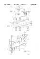
- FIG. 6there is illustrated a diagrammatic view of a typical plant that may exist at a manufacturing facility.
- the planttypically comprises a boiler 92 which has a firebox 94 disposed at the lower end thereof.
- the boiler 92interfaces with a stack 96 through a preheat chamber 98.
- Many tubes of which tube 100 is typical thereofare operable to run through the chamber 98 and enter the boiler 92.
- the tube 100then passes in a serpentine manner through the boiler 92 to an output pressure vessel 104, which is pressurized.
- the vessel 104is operable to generate steam out of an outlet 106.
- the other end of the tube 100 that enters the chamber 98is connected to a source 108 of the deionized water.
- the wateris passed through the tube 100 to the chamber 98, which picks up heat therein and then into the main boiler 92, where it is heated further. This then passes through to the vessel 104.
- the firebox 94has a heating element 116 associated therewith that is operable to receive gas through a gas line 118 and air through an air line 120. The mixture of the gas and the air allows the heating element 116 to generate heat in the firebox 94 and heat up the water in the tube 100 within the boiler 92.
- the tube 100when it exits the source 108 with the deionized water at the source, has the flow thereof measured by the flow meter 122.
- a valve 124allows control of the flow of fluid from the source 108 into the chamber 98.
- Two temperature sensors 126 and 128are provided at different locations along the tube 100 within the chamber 90 to provide temperature measurements therefor. Additionally, temperature sensors 130, 132 and 134 are provided along the tube 100 at various locations within the main boiler 92.
- a temperature sensor 136is provided for the firebox 94.
- the level of the fluid within the pressure vessel 104is measured by a level meter 142 and the pressure therein is measured by a pressure meter 146.
- a flow meter 150is provided for measuring the flow of steam out of the pressure vessel and a control valve 152 provides control of the steam exiting the pressure vessel 104.
- the heater element 116is controlled with a valve 158 on the gas line, which has the flow thereof measured by a flow meter 160.
- the flow meter on the air line 120is measured by a flow meter 162.
- a damper 163 in the stack 96is utilized to control air flow through the firebox 94.
- the sensor values s(t) of the plantare provided by the various temperature and flow measurement devices.
- the control valuesin the form of the various valves and damper positions provide the control values to the plant. Therefore, an operator can control the operation of the plant by controlling the various flow meters and other control values, some of which are not illustrated.
- the remaining inputs that are necessary in order to provide adequate control of the plant for the purpose of continuous emissions monitoringare the NOx levels. These are provided by the virtual sensor network 18 of FIG. 1. However, as described above, periodically a portable unit 170, having disposed thereon a CEM 172, is connected via a duct 174 to the stack 96 to measure the amount of NOx in the output emissions to the air.
- the CEM 172then generates a report as to the level of the NOx. If this level is within acceptable standards, then this is merely reported. However, if the level is outside of acceptable limits, this is reported to the plant operator and either changes are made or the plant is shut down. Additionally, the information generated by the CEM 172 is generated on a time base and this comprises training data. This training data, since it is on a common time base, can then be combined or merged with data associated with the sensor values and the control values, which are also on a time base, to provide new training data for the virtual sensor network 18. This can be utilized by the training system 20 to retrain the virtual sensor network 18, if necessary.
- FIG. 7there is illustrated a block diagram of the preferred embodiment for the sensor validation system 22.
- the sensor validation system 22To ensure that the overall inputs x(t) to the network 18 are "valid", it is necessary to perform some type of comparison with expected or predicted values. If it is suspected that the generated values are not accurate, then an alarm is generated to advise the plant operator or the control system of the need to calibrate the sensor or to repair the sensor, and an estimated or predicted value for that sensor value is substituted for the actual measured value of the sensor.
- an auto associative predictive neural network 180is provided which is a network having an input layer for receiving select ones of the inputs x(t) on an input 182.
- an input layerfor receiving select ones of the inputs x(t) on an input 182.
- only certain ones of the actual sensor valuesare necessary as inputs to the virtual sensor network 18 in order to provide an accurate prediction of the NOx levels that would generally be provided by the pollutant sensor 14. These are determined by performing a sensitivity analysis. This is described in U.S. patent application Ser. No. 056,197, filed Apr. 30, 1993 and entitled “Method and Apparatus for Determining the Sensitivity of Inputs to a Neural Network on Output Parameters" (Atty. Dkt. No.
- the actual inputs x(t)are input to a multiplexer 186 which is operable to select between the predicted inputs x p (t) output by the network 180, which is a predicted output, and the actual inputs x(t).
- a first cycleoccurs when the multiplexer selects the actual inputs x(t).
- the predicted inputs x p (t)are then input to a subtraction circuit 188 to determine the difference between x(t) and x p (t). This difference is input to comparator 190 for comparison with thresholds stored in a threshold memory 192.
- the one of the actual inputs to the network 180 having associated therewith the largest error as compared to the acceptable thresholdis then connected to the associated predicted output of the network 180.
- the actual inputs x(t) with the substituted or reconnected inputis then again cycled through the auto associative predictive network 180.
- the difference between the actual and the predicted valuesare again determined, compared with the thresholds, and the one of the actual inputs having the largest error is reconnected to the associated predicted input by the multiplexer 186.
- the predicted values from the network 180are input to a multiplexer 196, and the multiplexer 196 selecting for output therefrom the actual values that were determined to be acceptable and the predicted values as a substitute for the actual values that were determined to be unacceptable.
- the predicted valuesare generated by running the network with the determined unacceptable actual values replaced with the associated predicted values by the multiplexor 186.
- the output of the multiplexor 196is then input to the virtual sensor network 18.
- the predicted input values output by the auto associative predictive network 180can be provided as the input to the virtual sensor network 18. This would then not require the multiplexer 196 and, in fact, the auto associative predictive network 180 can continually monitor and replace ones of the sensor inputs that are determined to be invalid.
- the networkis comprised of an input layer of nodes 198 and an output layer of nodes 200.
- there is a single node for each of the predicted output variables x p (t)such that there are outputs x 1 p (t), x 2 p (t) . . . X A p (t).
- the input layer of nodes 198is mapped through to the output layer of nodes 200 through a hidden layer of nodes 202.
- the hidden layer of nodes 202has a plurality of interconnections with each of the nodes in the input layer of nodes and each of the output layer of nodes 200. Each of these interconnections is weighted. Further, the number of nodes in the hidden layer of nodes 202 is less than the number of nodes in either the input layer 198 or the output layer 200. This is therefore referred to as a bowtie network.
- the network 180can be trained via a back propagation training technique. This is described in D. E. Rumelhart, G. E. Hinton and R. J. Williams, "Learning Internal Representations by Propagations" in D. E. Rumelhart and J. L. McClelland, Parallel Distributive Processing, Vol. 1, 1986.
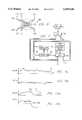
- FIGS. 9a and 9bthere are illustrated two plots depicting operation of the sensor validation system 22.
- the actual inputsare represented by X A and the predicted input is represented by X p . It can be seen that the predicted input does not exactly follow the actual input, it being noted that the actual input is actually the input to the overall system. The difference between the actual and the predicted input values is illustrated in FIG. 9b.
- FIGS. 10a and 10bthere is illustrated corresponding plots to those of FIGS. 9a and 9b with the exception that the sensor generating the actual input fails. It can be seen that up to a point 204 on the curve X a , the predicted and actual sensor values track fairly well with minimal error. However, at the point 204 the error increases dramatically, indicating that the sensor no longer provides an value that corresponds to the predicted value. This is illustrated in FIG. 10b, wherein the error increases. When the difference between X A and X p is greater than a threshold, this indicates an invalid reading. However, as noted above, only the one of the sensors having the highest error above the threshold will be selected as replacement value by the multiplexer 86 for the next cycle.
- FIG. 11there is illustrated a flowchart depicting the overall operation of the system.
- the flowchartis initiated at a start block 208 and then flows to a decision block 210.
- Decision block 210determines whether the remote CEM has been installed. If so, the program then flows to a function block 212 to measure the NOx levels with the remote CEM.
- the programthen flows to a decision block 214 to determine whether the measured NOx values, measured in function block 212, are acceptable. If not, this indicates that the virtual sensor network 18 is out of spec and that the system has either changed or the network no longer represents the system.
- the programwill then flow along an "N" path to a function block 216 to measure the system variables and then to a function block 218 to generate a training database.
- a training databaseessentially utilizes the system variables that are measured along the same time base as the measured NOx levels.
- the remote CEMwill be placed adjacent to the manufacturing facility and the pollutants measured for a predetermined amount of time, which can be measured in hours, days or weeks.
- the plant facilityitself is measuring the plant variables. These are also placed on a time base and stored.
- a training databasecan be provided for training the virtual sensor network 18. This time merging operation is described in U.S. patent application Ser. No. 07/980,664, filed Nov. 24, 1993 and entitled "Method and Apparatus for Operating a Neural Network with Missing and/or Incomplete Data".
- the virtual sensor network 18is trained, as indicated by a function block 220. This essentially generates weights, which can then be substituted for the neural network weights in the virtual sensor network 18.
- the programthen flows to a function block 222 to substitute new weights in the virtual sensor network 18. Thereafter, the program flows to a main operating portion of the program, which is initiated at a function block 224 to validate the sensors.
- the programwould flow from the decision block 218 along a "Y" path to the input of function block 224 to bypass the training step. Additionally, if the remote CEM is not present, the program would flow along an "N" path from the decision block 210 to the input of the sensor validation block 224.
- the sensor validation block 224validates the sensors and, if one is found invalid, it substitutes a predicted value for that invalid sensor.
- the programwould then flow to a function block 226 to determine if certain sensors needed to be replaced by predicted values. If so, the program would flow along a "Y" path to replace the invalid sensors with the predicted sensor value.
- the programwould then flow to a function block 232 to predict the pollutant value and then to a function block 232 to control the plant. The program would then flow back to a decision block 210. If it were determined that sensors did not need to be replaced by their predicted values, the program would flow along an "N" path from the decision block 226 to the input of function block 230.
- FIG. 12there is illustrated a function block depicting the operation of the sensor validation.
- the programis initiated at a start block 240 and then flows to a function block 242 to input the various sensor readings.
- the programthen flows to a function block 244 to run the sensor validation model and then to a decision block 246 to compare the predicted input values with the thresholds and generate an error signal when any of the predicted input values exceed the thresholds for that given variable, it being noted that there can be a threshold for each variable as to what constitutes an error for that sensor value.
- the programflows to a function block 248 to replace the largest input error with the mean value for that input. An alarm is generated at this point to warn of the failed sensor.
- the programwill then flow back the input of a function block 244.
- the programwill flow from a decision block 246 to a function block 250 to replace all detected errors with predicted sensor values and then to a function block 252 to output reconciled sensor values. The program will then flow to a return block 254.
- the internal combustion engine 260receives air on an intake port 262. This is input to a butterfly valve 264 which is basically the throttle valve that is controlled by the foot pedal on an automobile. The butterfly valve then feeds the restricted airflow to an intake manifold 266, which is input to the internal combustion engine 260.
- the fuel injection valve 268is operable to inject fuel into the intake manifold 266 in a regulated amount, which is determined by a number of factors, this being conventional.
- the internal combustion engine 260exhausts the combustion ingredients into an exhaust manifold 270.
- the exhaust manifold 270is connected to an exhaust pipe 272 which is connected to the input of a catalytic converter 274.
- the catalytic converter 274then interfaces with the tail pipe 276 to output the combustion gases.
- the exhaust manifold 270is connected through a pipe 278 to an emissions gas recirculation valve (EGR) 280.
- the EGR 280is interfaced with the intake manifold 266 through a pipe 282.
- the EGR 280is a conventional pollution control device that is operable to bleed off a small portion of the exhaust gases from the exhaust manifold 270 back into the intake manifold for recombustion thereof.
- EGR valvestypically operate at higher RPMs of the engine, as the recirculation of the exhaust gases at low RPMs causes the engine to idle roughly.
- an oxygen sensor 286is disposed in the exhaust manifold 270.
- the oxygen sensor 270basically provides for measurement of the exhaust gas ingredient concentration, typically oxygen, that exists in the exhaust manifold 270.
- These type of sensorsare utilized for air-fuel ratio control systems.
- the sensoris input to a central processing unit (CPU) 288 which controls the operation of the fuel injectors through a line 290 and the fuel supply thereto. Again, these are conventional systems.
- the CPU 288is operable to monitor a large number of parameters regarding the internal combustion engine, which parameters require some type of sensors.
- the operation of the ignitioni.e., spark advance, timing, etc.
- the manifold temperatureis provided by a manifold temperature sensor (TM) 294 and the cylinder temperature is provided by a cylinder temperature sensor (TCYL) 296.
- TMmanifold temperature sensor
- TTYLcylinder temperature sensor
- the sensors 294 and 296allow a temperature measurement to be made of each cylinder and the overall manifold.
- the back pressure in the exhaust pipe 270is provided by a pressure sensor (PEX) 298 and the pressure in the intake manifold is provided by a pressure sensor (PMAN) 300.
- PEXpressure sensor
- PMANpressure sensor
- the pressure sensor 300measures a vacuum for a conventional engine, which could be a positive pressure when the system is operated in conjunction with a turbocharger.
- the intake manifold temperatureis provided by a temperature sensor (TA) 302, which is connected to the intake manifold 266.
- the position of the butterfly valve 264is provided by a position sensor ( ⁇ th) 306.
- the temperature of the catalytic converteris measured by a temperature sensor (TCAT) 308.
- the CPU 288incorporates the full sensor system as described hereinabove and is operable to predict the emissions emitted by the internal combustion engine which, in the preferred embodiment, are primarily NOx, and either output this information in the form of a display, store it as a history or utilize it to control the operation of the engine.
- an emissions control system 308is provided, which is operable to control certain parameters of the system.
- one parameter that could be controlledis the internal threshold to the CPU 288 that determines the air-fuel ratio.
- the oxygen sensor 286operates on a threshold such that when it is above the threshold, the air-fuel mixture is changed in one direction and, when the oxygen sensor falls below the threshold, the air-fuel ratio is changed in the other direction.
- the thresholdBy changing the threshold, the average air-fuel ratio will be changed, and therefore, the actual emissions output can also be changed. This will be described in more detail hereinbelow.
- thresholdscan be loaded into the CPU 288, which thresholds can be selected in accordance with predetermined criteria. Additionally, a history can be provided of the vehicle as to the emissions generated by the engine and this stored for downloading at a later time for the purpose of monitoring the operation of the vehicle and the associated engine.
- the modelSince the emissions prediction is achieved utilizing a model of the system which utilizes the sensor outputs as inputs to provide the predicted output, the model must be initially trained. This initial training operation can be done on a "generic" engine with a "standard” emissions monitor and the then the model parameters downloaded to a standard integrated circuit which is utilized for all vehicles. This assumes that the model trained on the generic system holds true with respect to all subsequent systems and the manufacturing tolerances associated therewith. However, even if the generic model does provide a true representation of all engines manufactured for a given type of engine in combination with a standard emissions monitor, the parameters of the engine will change over time. It may therefore be necessary to update the training. This can be achieved in two ways.
- the emissionscan be measured with an emissions sensor that is external to the vehicle and not an integral part thereof and this compared to the predicted emissions output. If an error exists that is too large, the system then can be retrained. The retraining can either be a complete retraining of the model or merely an update of the training weights. In any event, this requires an actual emissions sensor to be utilized.
- the modelcan have a "bias" applied thereto to provide a slight offset. This also requires actual emissions to be monitored. The actual values are necessary to know how to adjust the bias.
- FIG. 14there is illustrated a block diagram of a system wherein an external emissions sensor 310 is utilized for training.
- the internal combustion engineis represented by a block 312, which receives inputs on a line 314 and provides measured outputs or state variables s(t) on lines 316, these comprising the inputs to the model.
- state variablesare first processed by sensor validation module 318, which was described hereinabove, and which is operable to substitute a predicted sensor output in the event of a failure of one of the sensors. This is described hereinabove with reference to FIGS. 7 and 8.
- the validated state variables s(t)'are output on lines 320 to a predictive model processor 322.
- the predictive model processor 322is operable to interface with the memory 324 for storing model parameters to process the parameters and provide a predicted output e(t) on a line 326. Additionally, the predictive model processor 322 is operable to store a time history of the predicted output in a memory 328.
- the model that is storedis a representation of the combined engine and emissions sensor. Therefore, the model will have associated therewith all aspects of both the engine and the emissions sensor. Even if the emissions sensor is inaccurate, the model is only as good as the sensor, but this inaccuracy must be incorporated into the model. This is important in that regulatory bodies require that the output measurement comply to their standards, which standards are defined by their equipment. If, for example, the emissions sensor that complied with their standards were in fact inaccurate, it would be important to predict an output with these inaccuracies. To correct these inaccuracies would not be acceptable. Therefore, the model is determined utilizing as part of the system the actual hardware sensor, which is removed during operation of the engine.
- the external emissions sensor 310is connected to the output of the internal combustion engine, which comprises a line 330 labelled y(t). This represents the output of the system. This is merely the output of the exhaust pipe.
- the emissions sensor 310is connected to the output to provide an actual output value of the emissions on a line 332. This is input to a difference device 334 to determine the difference between the output of the emissions sensor 310 and the predicted output on line 326. This generates an error E, which is input to a comparator 336.
- the comparator 336compares the error E with a predetermined threshold and then outputs a "Train" signal on a line 340. If the error exceeds the threshold, a training operation is initiated.
- the predictive model processor 322then enters into a training mode utilizing the actual emissions sensor outputs on a line 344 and the state variable inputs 320 to retrain the model. These parameters are then input to the memory 324. After training, the system will again be validated by comparing the operation of the internal combustion engine and the emissions output thereby with the predicted emissions output. Once the error has been minimized, i.e., reduced below the threshold, the system will be "validated".
- the predictive model processor 320can train the network by two methods. In the first method, it can completely regenerate model parameters from scratch utilizing a typical training algorithm. In the second method, it can merely update the model parameters, i.e., provide a minor adjustment thereto in order to reduce the error.
- the retraining processor 346is operable to receive on the input thereof the output state variables from the internal combustion engine 312 on lines 348, the actual output emissions sensor on the line 332 and the error output of the difference device 334. The retraining processor 346 then determines whether retraining is necessary, and if so, the retraining processor 346 will either update the model parameters or generate a new set of model parameters. During an update process, the old model parameters from the memory 324 are uploaded and adjusted and then downloaded back to the memory 324. In the complete training process, completely new model parameters are generated and then downloaded to the memory 324. Of course, after retraining or any modification of the model parameters 324, the system is again checked.
- backpropagationIn the training of the network, one technique that can be utilized is backpropagation, as described in D. E. Rumelhart, G. E. Hinton, and R. J. Williams, "Learning Internal Representations by Error Propagation" in D. E. Rumelhart & J. L. McClelland, Parallel Distributed Processing, Vol. 1, 1986.
- this techniqueas applied to a neural network, training is achieved by minimizing the Least Mean Square Errors with backpropagation. This utilizes the technique of steepest descents, wherein the weights W ij of a neural network and the parameters associated with the activation function are varied to minimize the error function.
- This backpropagation techniqueis essentially a common, non-linear least squares algorithm.
- z(t)specified target output for a given output pattern.
- the term y(t)contains contributions from the outputs of hidden units in a hidden layer. Because the hidden layer has a non-linear transfer function, the output of the hidden layer will be an output of the non-linear function of its input and the error E becomes a square of non-linear function weights since the hidden layer outputs are fed into the topmost output layer in a conventional three layer neural network.
- the backpropagation algorithmis described in the literature and also described in U.S. Pat. No. 5,113,483 issued May 12, 1992 and entitled "Network with Semi-Localized Non-Linear Mapping of the input Space". This patent is incorporated herein by reference.
- a neural networkIn addition to backpropagation, other techniques for training a neural network can be utilized, such as radial basis functions or Gaussian bars. Further, it is not necessary to utilize a neural network to provide a stored representation of the system. A fuzzy system (which is very similar to a radial basis function network) can also be utilized.
- FIG. 16there is illustrated a block diagram depicting the runtime operation of the internal combustion engine 312.
- the system of FIG. 16utilizes a control network 350 which is operable to receive the control input x(t) on line 314, the validated sensor outputs s(t)' on lines 320 and output updated control inputs x(t+1) on a line 352.
- the control network 350is described above with reference to FIG. 5a and can actually incorporate the model that is implemented by the predicted model processor.
- a desired or target emissions levelis input thereto.
- the line 352is input to an engine control system 354 which is operable to effect the various controls on the internal combustion engine. Any one of the controls can be manipulated to control the emissions within predetermined guidelines, these controls associated with controlling he air-fuel ratio.
- the overall systemis controlled by a runtime operating system 354 which is operable to receive the predicted output on the line 326 from the predictive model processor 322 and also receive the output of the sensor validation module 318 indicating which, if any, of the sensors have been determined to be in error. This information, in addition to the predicted emissions value output on line 326 is then utilized by the runtime operating system to either store it in the memory 328 associated with the historical information or make various decisions as to what should be done with respect to the predicted emissions information.
- Runtime thresholdsare prestored in a memory 356 and are utilized by the runtime operating system for comparison with the predicted emissions. If the predicted emissions exceed the selected one of the thresholds, some action must be taken. For example, emissions may be acceptable at one threshold in one area of the country and unacceptable in another area of the country. Further, the predicted emissions levels may also have an acceptability that is a function of other parameters, such as temperature and humidity.
- the runtime thresholdscould be selected as a function of atmospheric conditions or other criteria. However, in the preferred embodiment, it is anticipated that thresholds will be selected as a function of the locale that the engine is disposed in. Further, they could even be selected as a function of the time of day.
- a user input 358is utilized to select the thresholds or input thresholds via an input/output circuit 360.
- the input/output circuit 360is operable to interface with a display 360 and also with a communication system 362.
- the display 360can be, for example, a warning light. Further, it could be some type of display that actually outputs an analog value in the form a "gas gauge" for viewing by the driver. This would allow the driver to actually view the emissions levels as a function of his driving conditions, etc.
- the communications system 362is provided such that industrial engines at remote sites can be controlled on a periodic basis to download the stored history information in memory 328 to a central station.
- each of the communication devices 374is operable to transmit information over a wireless communication path via an antenna 376, which antenna 376 can operate in both a receive mode and a transmit mode.
- the antennas 376are operable to communicate with an antenna 378 on a command station 380.
- the protocol utilized for the transmissioncan be any type of conventional protocol. Although a wireless system is illustrated, it should be understood that a fixed wire system could be utilized.
- the networkcould have the parameters thereof offset or a bias adjust applied thereto.
- the networkcould have the parameters thereof offset or a bias adjust applied thereto.
- FIG. 18wherein the average of the plant output drifts by some amount. This situation is illustrated in FIG. 18, wherein a solid curve is illustrated representing the actual emissions output measured by an external emissions monitor and the dotted line represents the predicted output from the virtual sensor. It can be seen that there is an average error that occurs over time. This average error is determined and utilized to determine an offset, the average error defined as follows:
- o pis the output value predicted by the model.
- This bias adjustmentmust be made periodically or in an ongoing manner, utilizing moving averages.
- a first principles modelcould be utilized.
- First principle modelsare well-known and rely upon the fact that there are only a small number of controls that can be tuned or adjusted on the internal combustion engine. Typically, this tuning or control takes the form of adjusting parameters, i.e., co-efficients in the model to minimize the error that exists between the model output and the actual plant or engine output.
- This procedureis completely analogous to training a neural network model. The differences between the two training operations occur in the method that the parameters appear in the model and perhaps the way in which they are adjusted.
- First principle modelsare often simpler than neural network models in that they are often linear and have fewer adjustment parameters.
- An example of the first principle models applied to NOx emissions from an internal combustion engineis as follows:
- T cis the cylinder temperature
- T mis the manifold temperature and the average of the difference therebetween is taken over all cylinders.
- kis the adjustable parameter.
- the parameter kcan be adjusted in the same iterative manner that one adjusts the parameters in a neural network model, i.e., by gradient descent; that is, one minimizes the overall error between the model and the plant as follows: ##EQU6## via iteratively changing k according to the gradient descent equation: ##EQU7## In the present case, this is simply:
- a simple control examplewould be a situation wherein if the NOx output was high, a signal would be issued that would result in reducing the air-fuel ratio by reducing the air and increasing the fuel.
- FIG. 19there is illustrated a flowchart depicting the overall runtime control operation.
- the programwould be initiated at a start block 386 and then proceeds to a function block 388 to compare the expected emissions value to an internal runtime threshold, it being remembered that these thresholds can be selected by the user for a particular circumstance.
- the programthen flows to a decision block 390 to determine if the expected or predicted emissions exceed the threshold. If so, this indicates that some control operation or failure mechanism must be performed.
- the programwould flow to a decision block 392 to determine if a control operation is present. If so, the program would flow along a "Y" path to a function block 394 to adjust the controls in accordance with the predetermined control operation which could utilize the first principles operation as described above, or a control network.
- the programwould then flow to a decision block 396 to determine if it is possible to effect an appropriate control. In order to determine this, maximum limits are set within the operating parameters of the engine by which the controls can be modified to reduce emissions. If these control limits are exceeded, the engine operation will deteriorate, even though the emissions was appropriate. If the maximum control limit has been exceeded, the program would flow along a "Y" path to a function block 398 to set the default settings for the emissions control parameters and then to a function block 400 to store the history. If the maximum control limit had not been exceeded the controls would be accepted and the program would flow along an "N" path from decision block 396 to the function block 400. If no controls were available, the program would also flow to the function block 400 from the decision block 392 along the "N" path thereof.
- the programwould flow to a decision block 402 to determine if an alarm operation were present. This could occur in the event that the comparison made at decision block 390 required an alarm to be set or if the presence of the default setting in the function block 398 required an alarm to be set. If an alarm is to be set, the program would flow along the "Y" path from decision block 402 to a function block 404 to set the alarm, this possibly being a light on the dashboard or an audible alarm. Further, this could be the existence of an alarm communication to a central station requiring a maintenance check. The program would then flow to a return block 406.
- the programwould flow from the decision block 402 along the "N" path to the return block 406. Similarly, if the predicted emissions did not exceed the threshold, the program would flow to the return block 406 along the "N" path from the decision block 390.
- the programis initiated at a start block 410 and then proceeds to a function block 412 to measure the actual emissions.
- the programthen flows to a function block 414 to compare the measured actual emissions to the expected or predicted value output by the virtual sensor.
- the programthen flows to a decision block 416 to determine if the difference between the measured actual emissions and the predicted value exceed the threshold. If so, the program would flow along a "Y" path to a decision block 418 to determine if a training operation is to be performed. If not, the program would flow along an "N" path to a function block 420 to update a record database and then to a return block 422. Similarly, if the error did not exceed the threshold, the program would flow from the decision block 416 along the "N" path to the function block 420.
- the programwould flow from the decision block 418 along a "Y" path to a decision block 424 to determine if a full training operation is to be performed. If yes, the program would flow along a "Y" path to a function block 426 to retrain a complete model and then to a function block 428 to download the model parameters back to the memory associated with the model parameters. The program will then flow to a return block 430. If a full training operation were not to be performed, i.e., a partial training operation only, the program would then flow along an "N" path from decision block 424 to a function block 432 to upload the model parameters that were in the system and then adjust these model parameters as indicated by a function block 434. After adjustment, the program would flow to the input of the function block 428 to download the model parameters. It should be understood that the training operation can be an on-board operation utilizing the model processor or an off-board operation utilizing an external processor.
- a system for predicting emissions in order to obviate the need for an actual emissions sensor on a reciprocating engineutilizes a predictive model that is trained on various sensor outputs from the reciprocating engine with a target output of the actual emissions taken during generation of the training data set. Once trained, the system can operate without the actual emissions sensor, but represents the actual output of the emissions sensor. Periodically, the model can be checked to determine if the predicted value has deviated more than a predetermined amount from an actual measurement by performing an actual measurement with an external emissions sensor. If the measurement has deviated, the system can be indicated as out of spec or the network can be retrained.
Landscapes
- Engineering & Computer Science (AREA)
- Physics & Mathematics (AREA)
- General Physics & Mathematics (AREA)
- Artificial Intelligence (AREA)
- Automation & Control Theory (AREA)
- Health & Medical Sciences (AREA)
- Evolutionary Computation (AREA)
- Chemical & Material Sciences (AREA)
- Software Systems (AREA)
- Medical Informatics (AREA)
- Computer Vision & Pattern Recognition (AREA)
- Combustion & Propulsion (AREA)
- Life Sciences & Earth Sciences (AREA)
- Immunology (AREA)
- Medicinal Chemistry (AREA)
- Analytical Chemistry (AREA)
- Biochemistry (AREA)
- General Health & Medical Sciences (AREA)
- Food Science & Technology (AREA)
- Pathology (AREA)
- Mathematical Physics (AREA)
- Human Computer Interaction (AREA)
- Mechanical Engineering (AREA)
- General Engineering & Computer Science (AREA)
- Testing And Monitoring For Control Systems (AREA)
- Feedback Control In General (AREA)
- Alarm Systems (AREA)
- Measuring Pulse, Heart Rate, Blood Pressure Or Blood Flow (AREA)
- Testing Of Engines (AREA)
- Exhaust Gas After Treatment (AREA)
- Electrical Control Of Air Or Fuel Supplied To Internal-Combustion Engine (AREA)
- Combined Controls Of Internal Combustion Engines (AREA)
- Testing Or Calibration Of Command Recording Devices (AREA)
- Treating Waste Gases (AREA)
- Control Of Non-Electrical Variables (AREA)
- Superstructure Of Vehicle (AREA)
- Fittings On The Vehicle Exterior For Carrying Loads, And Devices For Holding Or Mounting Articles (AREA)
- Cooling, Air Intake And Gas Exhaust, And Fuel Tank Arrangements In Propulsion Units (AREA)
Abstract
Description
o(t)=f(x(t),P) (3)
(e)=(o.sub.a -o.sub.p) (7)
o.sub.p.sup.l =o.sub.p +(e) (8)
(e.sup.l)=(o.sub.a -o.sub.p.sup.l)=(o.sub.a)-(o.sub.p)-(o.sub.a)+(o.sub.p)=0(9)
NOx.sub.ppm =k(T.sub.c -T.sub.m) (10)
ΔK=ηe(T.sub.c -T.sub.M) (13)
Claims (15)
Priority Applications (16)
| Application Number | Priority Date | Filing Date | Title |
|---|---|---|---|
| US08/149,216US5539638A (en) | 1993-08-05 | 1993-11-05 | Virtual emissions monitor for automobile |
| AU73758/94AAU688353B2 (en) | 1993-08-05 | 1994-07-27 | Virtual emissions monitor for automobile |
| AU74776/94AAU677694B2 (en) | 1993-08-05 | 1994-07-27 | Virtual continuous emission monitoring system with sensor validation |
| DE69423895TDE69423895T2 (en) | 1993-08-05 | 1994-07-27 | VIRTUAL CONTINUOUS EMISSION MONITORING SYSTEM WITH VALIDITY CONFIRMATION OF THE PROBE |
| PCT/US1994/008657WO1995004878A1 (en) | 1993-08-05 | 1994-07-27 | Virtual emissions monitor for automobile |
| CA002167927ACA2167927A1 (en) | 1993-08-05 | 1994-07-27 | Virtual emissions monitor for automobile |
| EP94922772AEP0712463B1 (en) | 1993-08-05 | 1994-07-27 | Virtual emissions monitor for automobile |
| DE69418199TDE69418199T2 (en) | 1993-08-05 | 1994-07-27 | VIRTUAL EMISSION MONITORING DEVICE FOR MOTOR VEHICLES |
| JP7506469AJPH09504346A (en) | 1993-08-05 | 1994-07-27 | Virtual exhaust gas monitoring method for automobiles |
| CA002167588ACA2167588A1 (en) | 1993-08-05 | 1994-07-27 | Virtual continuous emission monitoring system with sensor validation |
| KR1019960700595AKR960704258A (en) | 1993-08-05 | 1994-07-27 | VIRTUAL CONTINUOUS EMISSION MONITORING SYSTEM WITH SENSOR VALIDATION With Sensor Effective Forecasting Network |
| EP94924530AEP0712509B1 (en) | 1993-08-05 | 1994-07-27 | Virtual continuous emission monitoring system with sensor validation |
| JP7506465AJPH09501782A (en) | 1993-08-05 | 1994-07-27 | Virtual continuous exhaust gas monitor with sensor evaluation |
| PCT/US1994/008628WO1995004957A1 (en) | 1993-08-05 | 1994-07-27 | Virtual continuous emission monitoring system with sensor validation |
| KR1019960700596AKR960704150A (en) | 1993-08-05 | 1996-02-05 | VIRTUAL EMISSIONS MONITOR FOR AUTOMOBILE |
| US08/685,072US5682317A (en) | 1993-08-05 | 1996-07-23 | Virtual emissions monitor for automobile and associated control system |
Applications Claiming Priority (2)
| Application Number | Priority Date | Filing Date | Title |
|---|---|---|---|
| US08/102,405US5386373A (en) | 1993-08-05 | 1993-08-05 | Virtual continuous emission monitoring system with sensor validation |
| US08/149,216US5539638A (en) | 1993-08-05 | 1993-11-05 | Virtual emissions monitor for automobile |
Related Parent Applications (1)
| Application Number | Title | Priority Date | Filing Date |
|---|---|---|---|
| US08/102,405Continuation-In-PartUS5386373A (en) | 1993-08-05 | 1993-08-05 | Virtual continuous emission monitoring system with sensor validation |
Related Child Applications (1)
| Application Number | Title | Priority Date | Filing Date |
|---|---|---|---|
| US08/685,072ContinuationUS5682317A (en) | 1993-08-05 | 1996-07-23 | Virtual emissions monitor for automobile and associated control system |
Publications (1)
| Publication Number | Publication Date |
|---|---|
| US5539638Atrue US5539638A (en) | 1996-07-23 |
Family
ID=26799346
Family Applications (2)
| Application Number | Title | Priority Date | Filing Date |
|---|---|---|---|
| US08/149,216Expired - LifetimeUS5539638A (en) | 1993-08-05 | 1993-11-05 | Virtual emissions monitor for automobile |
| US08/685,072Expired - LifetimeUS5682317A (en) | 1993-08-05 | 1996-07-23 | Virtual emissions monitor for automobile and associated control system |
Family Applications After (1)
| Application Number | Title | Priority Date | Filing Date |
|---|---|---|---|
| US08/685,072Expired - LifetimeUS5682317A (en) | 1993-08-05 | 1996-07-23 | Virtual emissions monitor for automobile and associated control system |
Country Status (8)
| Country | Link |
|---|---|
| US (2) | US5539638A (en) |
| EP (2) | EP0712509B1 (en) |
| JP (2) | JPH09504346A (en) |
| KR (2) | KR960704258A (en) |
| AU (2) | AU677694B2 (en) |
| CA (2) | CA2167588A1 (en) |
| DE (2) | DE69418199T2 (en) |
| WO (2) | WO1995004878A1 (en) |
Cited By (199)
| Publication number | Priority date | Publication date | Assignee | Title |
|---|---|---|---|---|
| US5675069A (en)* | 1995-03-10 | 1997-10-07 | Robert Bosch Gmbh | Circuit for processing a signal of a measuring sensor |
| US5703777A (en)* | 1994-10-20 | 1997-12-30 | Anr Pipeline Company | Parametric emissions monitoring system having operating condition deviation feedback |
| US5704011A (en)* | 1994-11-01 | 1997-12-30 | The Foxboro Company | Method and apparatus for providing multivariable nonlinear control |
| US5781871A (en)* | 1994-11-18 | 1998-07-14 | Robert Bosch Gmbh | Method of determining diagnostic threshold values for a particular motor vehicle type and electronic computing unit for a motor vehicle |
| US5832194A (en)* | 1996-02-24 | 1998-11-03 | Hella Kg Hueck & Co. | Electronic apparatus, process for its duplication, and arrangement for data transfer between two similarly constructed electronic apparatus |
| EP0877309A1 (en)* | 1997-05-07 | 1998-11-11 | Ford Global Technologies, Inc. | Virtual vehicle sensors based on neural networks trained using data generated by simulation models |
| WO1999025965A1 (en) | 1997-11-14 | 1999-05-27 | Engelhard Corporation | VEHICULAR ON-BOARD MONITORING SYSTEM SENSING COMBINED HC/NOx EMISSIONS FOR CATALYTIC CONVERTER EVALUATION |
| US5941918A (en)* | 1997-07-30 | 1999-08-24 | Engelhard Corporation | Automotive on-board monitoring system for catalytic converter evaluation |
| US5970426A (en)* | 1995-09-22 | 1999-10-19 | Rosemount Analytical Inc. | Emission monitoring system |
| WO2000017499A1 (en)* | 1998-09-24 | 2000-03-30 | Siemens Aktiengesellschaft | Method and device for catalytically reducing emission concentrations in the exhaust gas of a combustion system |
| US6071476A (en)* | 1997-11-14 | 2000-06-06 | Motorola, Inc. | Exhaust gas sensor |
| WO2001016571A1 (en)* | 1999-08-27 | 2001-03-08 | Rosemount Inc. | Prediction of error magnitude in a pressure transmitter |
| US6216083B1 (en)* | 1998-10-22 | 2001-04-10 | Yamaha Motor Co., Ltd. | System for intelligent control of an engine based on soft computing |
| US6240343B1 (en)* | 1998-12-28 | 2001-05-29 | Caterpillar Inc. | Apparatus and method for diagnosing an engine using computer based models in combination with a neural network |
| DE10010681A1 (en)* | 2000-03-04 | 2001-09-06 | Heinz J Theuerkauf | Simulating signal from electronic sensor in motor vehicle using virtual sensor in vehicle control device, based on neural network model |
| US6298718B1 (en) | 2000-03-08 | 2001-10-09 | Cummins Engine Company, Inc. | Turbocharger compressor diagnostic system |
| US20020055826A1 (en)* | 2000-03-30 | 2002-05-09 | Wegerich Stephan W. | Signal differentiation system using improved non-linear operator |
| US6405122B1 (en)* | 1997-10-14 | 2002-06-11 | Yamaha Hatsudoki Kabushiki Kaisha | Method and apparatus for estimating data for engine control |
| US6427438B1 (en)* | 1999-11-12 | 2002-08-06 | Honda Giken Kogyo Kabushiki Kaisha | Method of evaluating deteriorated state of catalytic converter for purifying exhaust gas |
| US20020133320A1 (en)* | 2001-01-19 | 2002-09-19 | Wegerich Stephan W. | Adaptive modeling of changed states in predictive condition monitoring |
| US6505517B1 (en) | 1999-07-23 | 2003-01-14 | Rosemount Inc. | High accuracy signal processing for magnetic flowmeter |
| US6519546B1 (en) | 1996-11-07 | 2003-02-11 | Rosemount Inc. | Auto correcting temperature transmitter with resistance based sensor |
| US6532392B1 (en) | 1996-03-28 | 2003-03-11 | Rosemount Inc. | Transmitter with software for determining when to initiate diagnostics |
| US20030055607A1 (en)* | 2001-06-11 | 2003-03-20 | Wegerich Stephan W. | Residual signal alert generation for condition monitoring using approximated SPRT distribution |
| US6539267B1 (en) | 1996-03-28 | 2003-03-25 | Rosemount Inc. | Device in a process system for determining statistical parameter |
| US6556939B1 (en) | 2000-11-22 | 2003-04-29 | Smartsignal Corporation | Inferential signal generator for instrumented equipment and processes |
| US20030139908A1 (en)* | 2001-04-10 | 2003-07-24 | Wegerich Stephan W. | Diagnostic systems and methods for predictive condition monitoring |
| US6601005B1 (en) | 1996-11-07 | 2003-07-29 | Rosemount Inc. | Process device diagnostics using process variable sensor signal |
| US6611775B1 (en) | 1998-12-10 | 2003-08-26 | Rosemount Inc. | Electrode leakage diagnostics in a magnetic flow meter |
| US6611735B1 (en) | 1999-11-17 | 2003-08-26 | Ethyl Corporation | Method of predicting and optimizing production |
| US6615149B1 (en) | 1998-12-10 | 2003-09-02 | Rosemount Inc. | Spectral diagnostics in a magnetic flow meter |
| US6615090B1 (en) | 1999-02-22 | 2003-09-02 | Fisher-Rosemont Systems, Inc. | Diagnostics in a process control system which uses multi-variable control techniques |
| US6629059B2 (en) | 2001-05-14 | 2003-09-30 | Fisher-Rosemount Systems, Inc. | Hand held diagnostic and communication device with automatic bus detection |
| US20030216855A1 (en)* | 2002-05-15 | 2003-11-20 | Liang Cho Y. | NOx emission-control system using a virtual sensor |
| US6697729B2 (en) | 2002-04-08 | 2004-02-24 | Cummins, Inc. | System for estimating NOx content of exhaust gas produced by an internal combustion engine |
| US6718251B2 (en) | 2002-01-29 | 2004-04-06 | Cummins, Inc. | System for controlling exhaust emissions produced by an internal combustion engine |
| US6721609B1 (en) | 2000-06-14 | 2004-04-13 | Fisher-Rosemount Systems, Inc. | Integrated optimal model predictive control in a process control system |
| US6754601B1 (en) | 1996-11-07 | 2004-06-22 | Rosemount Inc. | Diagnostics for resistive elements of process devices |
| US6772036B2 (en) | 2001-08-30 | 2004-08-03 | Fisher-Rosemount Systems, Inc. | Control system using process model |
| US6775641B2 (en) | 2000-03-09 | 2004-08-10 | Smartsignal Corporation | Generalized lensing angular similarity operator |
| US20040199324A1 (en)* | 2003-04-01 | 2004-10-07 | Xiaoqiu Li | System for diagnosing operation of a cooling system for an internal combustion engine |
| US20040230368A1 (en)* | 2003-05-14 | 2004-11-18 | Kropinski Michael A. | Method and apparatus to diagnose intake airflow |
| US6859755B2 (en) | 2001-05-14 | 2005-02-22 | Rosemount Inc. | Diagnostics for industrial process control and measurement systems |
| US20050089811A1 (en)* | 2003-10-24 | 2005-04-28 | United Dominion Industries, Inc. | Exhaust recirculating method and apparatus for a hydrocarbon fired burner |
| US20050114010A1 (en)* | 2003-11-20 | 2005-05-26 | General Electric Company | Method for controlling fuel splits to gas turbine combustor |
| US6901300B2 (en) | 2002-02-07 | 2005-05-31 | Fisher-Rosemount Systems, Inc.. | Adaptation of advanced process control blocks in response to variable process delay |
| US20050119986A1 (en)* | 2003-07-25 | 2005-06-02 | Panfilov Sergey A. | Soft computing optimizer of intelligent control system structures |
| US20050125117A1 (en)* | 1995-06-07 | 2005-06-09 | Breed David S. | Vehicular information and monitoring system and methods |
| US6907383B2 (en) | 1996-03-28 | 2005-06-14 | Rosemount Inc. | Flow diagnostic system |
| US6912889B2 (en) | 2001-02-19 | 2005-07-05 | Rosemount Analytical Inc. | Generator monitoring, control and efficiency |
| US6920799B1 (en) | 2004-04-15 | 2005-07-26 | Rosemount Inc. | Magnetic flow meter with reference electrode |
| WO2005085964A1 (en)* | 2004-03-04 | 2005-09-15 | Bayerische Motoren Werke Aktiengesellschaft | Process control system |
| US6957172B2 (en) | 2000-03-09 | 2005-10-18 | Smartsignal Corporation | Complex signal decomposition and modeling |
| US6970003B2 (en) | 2001-03-05 | 2005-11-29 | Rosemount Inc. | Electronics board life prediction of microprocessor-based transmitters |
| US7010459B2 (en) | 1999-06-25 | 2006-03-07 | Rosemount Inc. | Process device diagnostics using process variable sensor signal |
| US7018800B2 (en) | 2003-08-07 | 2006-03-28 | Rosemount Inc. | Process device with quiescent current diagnostics |
| US20060069541A1 (en)* | 2004-09-30 | 2006-03-30 | Ford Motor Company | Reuse of manufacturing process design models as part of a diagnostic system |
| US7046180B2 (en) | 2004-04-21 | 2006-05-16 | Rosemount Inc. | Analog-to-digital converter with range error detection |
| US20060102121A1 (en)* | 2004-11-12 | 2006-05-18 | Detroit Diesel Corporation | Internal EGR for an internal combustion engine |
| US7085610B2 (en) | 1996-03-28 | 2006-08-01 | Fisher-Rosemount Systems, Inc. | Root cause diagnostics |
| EP1693558A1 (en)* | 2005-02-16 | 2006-08-23 | ABB Technology AG | Method of forecasting of pollutant emissions of combustion processes |
| US20060218108A1 (en)* | 2005-03-24 | 2006-09-28 | Sergey Panfilov | System for soft computing simulation |
| US20060224547A1 (en)* | 2005-03-24 | 2006-10-05 | Ulyanov Sergey V | Efficient simulation system of quantum algorithm gates on classical computer based on fast algorithm |
| US20060229753A1 (en)* | 2005-04-08 | 2006-10-12 | Caterpillar Inc. | Probabilistic modeling system for product design |
| US20060229852A1 (en)* | 2005-04-08 | 2006-10-12 | Caterpillar Inc. | Zeta statistic process method and system |
| US20060229769A1 (en)* | 2005-04-08 | 2006-10-12 | Caterpillar Inc. | Control system and method |
| US20060230097A1 (en)* | 2005-04-08 | 2006-10-12 | Caterpillar Inc. | Process model monitoring method and system |
| US20060229854A1 (en)* | 2005-04-08 | 2006-10-12 | Caterpillar Inc. | Computer system architecture for probabilistic modeling |
| US20060242945A1 (en)* | 2005-05-02 | 2006-11-02 | Wang Yue Y | Method and apparatus for diagnosing exhaust gas aftertreatment component degradation |
| US20060293817A1 (en)* | 2005-06-23 | 2006-12-28 | Takahide Hagiwara | Intelligent electronically-controlled suspension system based on soft computing optimizer |
| US20070061144A1 (en)* | 2005-08-30 | 2007-03-15 | Caterpillar Inc. | Batch statistics process model method and system |
| US20070078529A1 (en)* | 2005-09-30 | 2007-04-05 | Fisher-Rosemount Systems, Inc. | On-line adaptive model predictive control in a process control system |
| US20070094048A1 (en)* | 2005-10-25 | 2007-04-26 | Caterpillar Inc. | Expert knowledge combination process based medical risk stratifying method and system |
| US20070118487A1 (en)* | 2005-11-18 | 2007-05-24 | Caterpillar Inc. | Product cost modeling method and system |
| US20070118338A1 (en)* | 2005-11-18 | 2007-05-24 | Caterpillar Inc. | Process model based virtual sensor and method |
| US20070149862A1 (en)* | 2005-11-29 | 2007-06-28 | Pipke Robert M | Residual-Based Monitoring of Human Health |
| US7251638B2 (en) | 2004-03-03 | 2007-07-31 | Yamaha Hatsudoki Kabushiki Kaisha | Intelligent robust control system for motorcycle using soft computing optimizer |
| US7254518B2 (en) | 1996-03-28 | 2007-08-07 | Rosemount Inc. | Pressure transmitter with diagnostics |
| US20070192078A1 (en)* | 2006-02-14 | 2007-08-16 | Edsa Micro Corporation | Systems and methods for real-time system monitoring and predictive analysis |
| US20070203810A1 (en)* | 2006-02-13 | 2007-08-30 | Caterpillar Inc. | Supply chain modeling method and system |
| US20070203864A1 (en)* | 2006-01-31 | 2007-08-30 | Caterpillar Inc. | Process model error correction method and system |
| US20070203616A1 (en)* | 2004-06-25 | 2007-08-30 | Eric Borrmann | Motor vehicle control device provided with a neuronal network |
| US20070225836A1 (en)* | 2005-03-18 | 2007-09-27 | Swanson Brian G | Predictive emissions monitoring system and method |
| US20070251218A1 (en)* | 2006-04-28 | 2007-11-01 | Driscoll James J | NOx control using a neural network |
| US20070255482A1 (en)* | 2005-01-07 | 2007-11-01 | Toyota Jidosha Kabushiki Kaisha | Evaluation Device for Control System, Validation Device Used in Evaluation Device, Method for Evaluating Control System, and Computer Program Used Therein |
| US7290450B2 (en) | 2003-07-18 | 2007-11-06 | Rosemount Inc. | Process diagnostics |
| US20070271014A1 (en)* | 1995-06-07 | 2007-11-22 | Automotive Technologies International, Inc. | Vehicle Diagnostic and Prognostic Methods and Systems |
| US7321846B1 (en) | 2006-10-05 | 2008-01-22 | Rosemount Inc. | Two-wire process control loop diagnostics |
| US20080040005A1 (en)* | 1995-06-07 | 2008-02-14 | Automotive Technologies International, Inc. | Vehicle Component Control Methods and Systems Based on Vehicle Stability |
| US20080046149A1 (en)* | 1995-06-07 | 2008-02-21 | Automotive Technologies International, Inc. | Vehicle Component Control Methods and Systems Based on Vehicle Stability |
| US20080147280A1 (en)* | 1995-06-07 | 2008-06-19 | Automotive Technologies International, Inc. | Method and apparatus for sensing a rollover |
| US20080147271A1 (en)* | 1995-06-07 | 2008-06-19 | Automotives Technologies International, Inc. | Vehicle Component Control Methods and Systems |
| US20080147265A1 (en)* | 1995-06-07 | 2008-06-19 | Automotive Technologies International, Inc. | Vehicle Diagnostic or Prognostic Message Transmission Systems and Methods |
| US20080154459A1 (en)* | 2006-12-21 | 2008-06-26 | Caterpillar Inc. | Method and system for intelligent maintenance |
| US20080154811A1 (en)* | 2006-12-21 | 2008-06-26 | Caterpillar Inc. | Method and system for verifying virtual sensors |
| US20080161989A1 (en)* | 1995-06-07 | 2008-07-03 | Automotive Technologies International, Inc. | Vehicle Diagnostic or Prognostic Message Transmission Systems and Methods |
| US20080201054A1 (en)* | 2006-09-29 | 2008-08-21 | Caterpillar Inc. | Virtual sensor based engine control system and method |
| US20080284575A1 (en)* | 1995-06-07 | 2008-11-20 | Automotive Technologies International, Inc. | Vehicle Diagnostic Techniques |
| US20080312756A1 (en)* | 2007-06-15 | 2008-12-18 | Caterpillar Inc. | Virtual sensor system and method |
| US20090018746A1 (en)* | 2004-05-06 | 2009-01-15 | Ricardo Uk Limited | Method and Apparatus For Measuring and Correcting an In-Cylinder Pressure Measurement |
| US20090037153A1 (en)* | 2007-07-30 | 2009-02-05 | Caterpillar Inc. | Product design optimization method and system |
| US20090063087A1 (en)* | 2007-08-31 | 2009-03-05 | Caterpillar Inc. | Virtual sensor based control system and method |
| US7502656B2 (en) | 1996-08-20 | 2009-03-10 | Invensys Systems, Inc. | Methods and apparatus for remote process control |
| US20090070047A1 (en)* | 2005-03-18 | 2009-03-12 | Swanson Brian G | Predictive emissions monitoring using a statistical hybrid model |
| US7523667B2 (en) | 2003-12-23 | 2009-04-28 | Rosemount Inc. | Diagnostics of impulse piping in an industrial process |
| US20090112334A1 (en)* | 2007-10-31 | 2009-04-30 | Grichnik Anthony J | Fixed-point virtual sensor control system and method |
| US20090118841A1 (en)* | 2007-11-02 | 2009-05-07 | Caterpillar Inc. | Virtual sensor network (VSN) system and method |
| US20090119065A1 (en)* | 2007-11-02 | 2009-05-07 | Caterpillar Inc. | Virtual sensor network (VSN) system and method |
| US7539597B2 (en) | 2001-04-10 | 2009-05-26 | Smartsignal Corporation | Diagnostic systems and methods for predictive condition monitoring |
| US20090165544A1 (en)* | 2007-12-31 | 2009-07-02 | Detroit Diesel Corporation | System and Method for Determining Non-Sensed Vehicle Operating Parameters |
| US20090182441A1 (en)* | 2008-01-15 | 2009-07-16 | Powitec Intelligent Technologies Gmbh | Control loop and method of creating a process model therefor |
| US7590511B2 (en) | 2007-09-25 | 2009-09-15 | Rosemount Inc. | Field device for digital process control loop diagnostics |
| US7623932B2 (en) | 1996-03-28 | 2009-11-24 | Fisher-Rosemount Systems, Inc. | Rule set for root cause diagnostics |
| US7627441B2 (en) | 2003-09-30 | 2009-12-01 | Rosemount Inc. | Process device with vibration based diagnostics |
| US20090293457A1 (en)* | 2008-05-30 | 2009-12-03 | Grichnik Anthony J | System and method for controlling NOx reactant supply |
| US20090300052A1 (en)* | 2008-05-30 | 2009-12-03 | Caterpillar Inc. | System and method for improving data coverage in modeling systems |
| US7630861B2 (en) | 1996-03-28 | 2009-12-08 | Rosemount Inc. | Dedicated process diagnostic device |
| US20100050025A1 (en)* | 2008-08-20 | 2010-02-25 | Caterpillar Inc. | Virtual sensor network (VSN) based control system and method |
| US20100083640A1 (en)* | 2008-10-06 | 2010-04-08 | Gm Global Technology Operations, Inc. | Engine-out nox virtual sensor using cylinder pressure sensor |
| US7739096B2 (en) | 2000-03-09 | 2010-06-15 | Smartsignal Corporation | System for extraction of representative data for training of adaptive process monitoring equipment |
| US20100168931A1 (en)* | 2006-04-12 | 2010-07-01 | Edsa Micro Corporation | Systems and methods for alarm filtering and management within a real-time data acquisition and monitoring environment |
| US7750642B2 (en) | 2006-09-29 | 2010-07-06 | Rosemount Inc. | Magnetic flowmeter with verification |
| US7761923B2 (en) | 2004-03-01 | 2010-07-20 | Invensys Systems, Inc. | Process control methods and apparatus for intrusion detection, protection and network hardening |
| US20100185358A1 (en)* | 2006-05-08 | 2010-07-22 | Lee Bernard | Emission monitoring device and method |
| US20100250202A1 (en)* | 2005-04-08 | 2010-09-30 | Grichnik Anthony J | Symmetric random scatter process for probabilistic modeling system for product design |
| US7831416B2 (en) | 2007-07-17 | 2010-11-09 | Caterpillar Inc | Probabilistic modeling system for product design |
| US20100305811A1 (en)* | 2007-11-28 | 2010-12-02 | Carl-Eike Hofmeister | Method and device for identifying errors in emission-relevant control devices in a vehicle |
| US20100318958A1 (en)* | 2009-06-15 | 2010-12-16 | International Business Machines Corporation | Managing componenet coupling in an object-centric process implementation |
| US7860857B2 (en) | 2006-03-30 | 2010-12-28 | Invensys Systems, Inc. | Digital data processing apparatus and methods for improving plant performance |
| US20110029250A1 (en)* | 2005-06-17 | 2011-02-03 | Venture Gain LLC | Non-Parametric Modeling Apparatus and Method for Classification, Especially of Activity State |
| US7890927B2 (en) | 1999-05-17 | 2011-02-15 | Invensys Systems, Inc. | Apparatus and method for configuring and editing a control system with live data |
| US7921734B2 (en) | 2009-05-12 | 2011-04-12 | Rosemount Inc. | System to detect poor process ground connections |
| US20110106506A1 (en)* | 2009-11-05 | 2011-05-05 | General Electric Company | PREDICTING NOx EMISSIONS |
| US7940189B2 (en) | 2005-09-29 | 2011-05-10 | Rosemount Inc. | Leak detector for process valve |
| US7949495B2 (en) | 1996-03-28 | 2011-05-24 | Rosemount, Inc. | Process variable transmitter with diagnostics |
| US7953501B2 (en) | 2006-09-25 | 2011-05-31 | Fisher-Rosemount Systems, Inc. | Industrial process control loop monitor |
| US20110216185A1 (en)* | 2010-03-02 | 2011-09-08 | INRO Technologies Limited | Method and apparatus for simulating a physical environment to facilitate vehicle operation and task completion |
| US20110218670A1 (en)* | 2010-03-05 | 2011-09-08 | INRO Technologies Limited | Method and apparatus for sensing object load engagement, transportation and disengagement by automated vehicles |
| US8090452B2 (en) | 1999-06-11 | 2012-01-03 | Invensys Systems, Inc. | Methods and apparatus for control using control devices that provide a virtual machine environment and that communicate via an IP network |
| US8112565B2 (en) | 2005-06-08 | 2012-02-07 | Fisher-Rosemount Systems, Inc. | Multi-protocol field device interface with automatic bus detection |
| US8127060B2 (en) | 2009-05-29 | 2012-02-28 | Invensys Systems, Inc | Methods and apparatus for control configuration with control objects that are fieldbus protocol-aware |
| US8157047B2 (en) | 1995-06-07 | 2012-04-17 | Automotive Technologies International, Inc. | Occupant protection systems control techniques |
| US20120095808A1 (en)* | 2010-10-15 | 2012-04-19 | Invensys Systems Inc. | System and Method for Process Predictive Simulation |
| US8209156B2 (en) | 2005-04-08 | 2012-06-26 | Caterpillar Inc. | Asymmetric random scatter process for probabilistic modeling system for product design |
| EP2413205A4 (en)* | 2009-03-27 | 2012-08-29 | Honda Motor Co Ltd | Controller for plant |
| US8275577B2 (en) | 2006-09-19 | 2012-09-25 | Smartsignal Corporation | Kernel-based method for detecting boiler tube leaks |
| US8290721B2 (en) | 1996-03-28 | 2012-10-16 | Rosemount Inc. | Flow measurement diagnostics |
| US8311774B2 (en) | 2006-12-15 | 2012-11-13 | Smartsignal Corporation | Robust distance measures for on-line monitoring |
| US20120310468A1 (en)* | 2011-06-06 | 2012-12-06 | INRO Technologies Limited | Method and apparatus for automatically calibrating vehicle parameters |
| US8364610B2 (en) | 2005-04-08 | 2013-01-29 | Caterpillar Inc. | Process modeling and optimization method and system |
| US8368640B2 (en) | 1999-05-17 | 2013-02-05 | Invensys Systems, Inc. | Process control configuration system with connection validation and configuration |
| US8463964B2 (en) | 2009-05-29 | 2013-06-11 | Invensys Systems, Inc. | Methods and apparatus for control configuration with enhanced change-tracking |
| US8589012B2 (en) | 2011-06-14 | 2013-11-19 | Crown Equipment Limited | Method and apparatus for facilitating map data processing for industrial vehicle navigation |
| US8594814B2 (en) | 2008-06-20 | 2013-11-26 | Invensys Systems, Inc. | Systems and methods for immersive interaction with actual and/or simulated facilities for process, environmental and industrial control |
| US8594923B2 (en) | 2011-06-14 | 2013-11-26 | Crown Equipment Limited | Method and apparatus for sharing map data associated with automated industrial vehicles |
| US8655588B2 (en) | 2011-05-26 | 2014-02-18 | Crown Equipment Limited | Method and apparatus for providing accurate localization for an industrial vehicle |
| US8768573B2 (en) | 2003-08-11 | 2014-07-01 | American Vehicular Sciences, LLC | Technique for ensuring safe travel of a vehicle or safety of an occupant therein |
| US8788070B2 (en) | 2006-09-26 | 2014-07-22 | Rosemount Inc. | Automatic field device service adviser |
| US8793004B2 (en) | 2011-06-15 | 2014-07-29 | Caterpillar Inc. | Virtual sensor system and method for generating output parameters |
| US8898036B2 (en) | 2007-08-06 | 2014-11-25 | Rosemount Inc. | Process variable transmitter with acceleration sensor |
| US9031824B2 (en) | 2006-07-19 | 2015-05-12 | Power Analytics Corporation | Real-time predictive systems for intelligent energy monitoring and management of electrical power networks |
| US9052240B2 (en) | 2012-06-29 | 2015-06-09 | Rosemount Inc. | Industrial process temperature transmitter with sensor stress diagnostics |
| US9056754B2 (en) | 2011-09-07 | 2015-06-16 | Crown Equipment Limited | Method and apparatus for using pre-positioned objects to localize an industrial vehicle |
| US20150176456A1 (en)* | 2013-12-23 | 2015-06-25 | Hyundai Motor Company | Method of determining correcting logic for reacting model of selective catalytic reduction catalyst, method of correcting parameters of reacting model of selective catalytic reduction catalyst and exhaust system using the same |
| US9092593B2 (en) | 2007-09-25 | 2015-07-28 | Power Analytics Corporation | Systems and methods for intuitive modeling of complex networks in a digital environment |
| US9188982B2 (en) | 2011-04-11 | 2015-11-17 | Crown Equipment Limited | Method and apparatus for efficient scheduling for multiple automated non-holonomic vehicles using a coordinated path planner |
| US9206023B2 (en) | 2011-08-26 | 2015-12-08 | Crown Equipment Limited | Method and apparatus for using unique landmarks to locate industrial vehicles at start-up |
| US9207670B2 (en) | 2011-03-21 | 2015-12-08 | Rosemount Inc. | Degrading sensor detection implemented within a transmitter |
| US20160237927A1 (en)* | 2015-02-12 | 2016-08-18 | GM Global Technology Operations LLC | Model Predictive Control Systems And Methods For Increasing Computational Efficiency |
| CN105888868A (en)* | 2015-02-12 | 2016-08-24 | 通用汽车环球科技运作有限责任公司 | Model Predictive Control Systems And Methods For Increasing Computational Efficiency |
| WO2017041983A1 (en)* | 2015-09-07 | 2017-03-16 | Jaguar Land Rover Limited | A verification module for verifying accuracy of a controller |
| US9602122B2 (en) | 2012-09-28 | 2017-03-21 | Rosemount Inc. | Process variable measurement noise diagnostic |
| US20170307215A1 (en)* | 2016-04-26 | 2017-10-26 | Cleaver-Brooks, Inc. | Boiler System and Method of Operating Same |
| EP2607861A3 (en)* | 2011-12-20 | 2017-11-29 | Honeywell International Inc. | Model based calibration of inferential sensing |
| EP2423768A3 (en)* | 2010-08-31 | 2018-01-17 | Rockwell Automation Technologies, Inc. | Sensor validation and value replacement for continuous emissions monitoring |
| US9920697B2 (en) | 2014-03-26 | 2018-03-20 | GM Global Technology Operations LLC | Engine control systems and methods for future torque request increases |
| US9938908B2 (en) | 2016-06-14 | 2018-04-10 | GM Global Technology Operations LLC | System and method for predicting a pedal position based on driver behavior and controlling one or more engine actuators based on the predicted pedal position |
| US20180137218A1 (en)* | 2016-11-11 | 2018-05-17 | General Electric Company | Systems and methods for similarity-based information augmentation |
| CN110168570A (en)* | 2016-12-29 | 2019-08-23 | 谷歌有限责任公司 | Machine learning virtual sensor process model for multiple sensors |
| US10408028B2 (en) | 2013-10-15 | 2019-09-10 | Halliburton Energy Services, Inc. | Optimization of engine emissions from equipment used in well site operations |
| CN110273738A (en)* | 2019-03-14 | 2019-09-24 | 吉林大学 | A heavy-duty engine emission diagnostic test system |
| US10489530B2 (en) | 2014-10-22 | 2019-11-26 | Siemens Aktiengesellschaft | Method for determining an emission behaviour |
| US10662765B2 (en)* | 2015-09-18 | 2020-05-26 | Schlumberger Technology Corporation | Wellsite emissions monitoring and control |
| US10769517B2 (en)* | 2016-03-05 | 2020-09-08 | Fujitsu Limited | Neural network analysis |
| CN111989625A (en)* | 2018-03-29 | 2020-11-24 | 安曼瑞士股份公司 | Emission control for asphalt mixing plant |
| US10867087B2 (en) | 2006-02-14 | 2020-12-15 | Wavetech Global, Inc. | Systems and methods for real-time DC microgrid power analytics for mission-critical power systems |
| US10962999B2 (en) | 2009-10-01 | 2021-03-30 | Wavetech Global Inc. | Microgrid model based automated real time simulation for market based electric power system optimization |
| US10972261B1 (en)* | 2019-10-18 | 2021-04-06 | Via Science, Inc. | Secure data processing |
| WO2021165406A1 (en)* | 2020-02-20 | 2021-08-26 | Evonik Operations Gmbh | Method and system for process control |
| US11113434B2 (en) | 2006-02-14 | 2021-09-07 | Power Analytics Corporation | Method for predicting arc flash energy and PPE category within a real-time monitoring system |
| US20210394772A1 (en)* | 2020-06-19 | 2021-12-23 | Ghost Locomotion Inc. | Handling input data errors in an autonomous vehicle |
| US11256597B2 (en) | 2019-11-14 | 2022-02-22 | International Business Machines Corporation | Ensemble approach to alerting to model degradation |
| US11455561B2 (en) | 2019-11-14 | 2022-09-27 | International Business Machines Corporation | Alerting to model degradation based on distribution analysis using risk tolerance ratings |
| US11537090B2 (en)* | 2016-09-07 | 2022-12-27 | Robert Bosch Gmbh | Model calculating unit and control unit for selectively calculating an RBF model, a gaussian process model and an MLP model |
| US20230065744A1 (en)* | 2021-08-26 | 2023-03-02 | Halliburton Energy Services, Inc. | Graphical user interface for abating emissions of gaseous byproducts from hydrocarbon assets |
| US11768917B2 (en) | 2019-11-14 | 2023-09-26 | International Business Machines Corporation | Systems and methods for alerting to model degradation based on distribution analysis |
| US11810013B2 (en) | 2019-11-14 | 2023-11-07 | International Business Machines Corporation | Systems and methods for alerting to model degradation based on survival analysis |
| KR102796216B1 (en)* | 2024-05-09 | 2025-04-16 | 주식회사 티오이십일콤즈 | Apparatus and method for implementing a framework for creating and operating virtual sensors |
| US12333799B2 (en) | 2018-07-20 | 2025-06-17 | Schlumberger Technology Corporation | Optimized multi-stage intermittent fugitive emission detection |
Families Citing this family (100)
| Publication number | Priority date | Publication date | Assignee | Title |
|---|---|---|---|---|
| US5539638A (en)* | 1993-08-05 | 1996-07-23 | Pavilion Technologies, Inc. | Virtual emissions monitor for automobile |
| DE19536571C2 (en)* | 1995-09-29 | 1998-09-03 | Siemens Ag | Method and device for metering the input of a reducing agent into the exhaust gas or exhaust air stream of an incineration plant |
| US6654697B1 (en) | 1996-03-28 | 2003-11-25 | Rosemount Inc. | Flow measurement with diagnostics |
| US5750886A (en)* | 1996-06-27 | 1998-05-12 | General Motors Corporation | Engine emissions analyzer with diagnostic |
| CA2276299A1 (en)* | 1996-12-31 | 1998-07-09 | Rosemount Inc. | Device in a process system for validating a control signal from a field device |
| EP0995115B1 (en)* | 1997-07-12 | 2004-05-19 | IDT Technology Limited | Device for monitoring the air quality |
| JPH1185719A (en)* | 1997-09-03 | 1999-03-30 | Matsushita Electric Ind Co Ltd | Parameter estimation device |
| JP3354088B2 (en)* | 1997-09-16 | 2002-12-09 | 本田技研工業株式会社 | Air-fuel ratio control system for exhaust system of internal combustion engine |
| JP3331159B2 (en)* | 1997-09-16 | 2002-10-07 | 本田技研工業株式会社 | Plant control equipment |
| JP3592519B2 (en)* | 1997-09-16 | 2004-11-24 | 本田技研工業株式会社 | Air-fuel ratio control device for exhaust system of internal combustion engine and control device for plant |
| JP3805098B2 (en)* | 1998-03-26 | 2006-08-02 | 株式会社日立製作所 | Engine exhaust gas purification control device |
| JP3484074B2 (en)* | 1998-05-13 | 2004-01-06 | 本田技研工業株式会社 | Plant control equipment |
| JP3484088B2 (en)* | 1998-12-17 | 2004-01-06 | 本田技研工業株式会社 | Plant control equipment |
| US6151547A (en)* | 1999-02-24 | 2000-11-21 | Engelhard Corporation | Air/fuel ratio manipulation code for optimizing dynamic emissions |
| US6353804B1 (en)* | 1999-04-09 | 2002-03-05 | General Electric Company | Method for statistically predicting equipment performance |
| JP4265704B2 (en)* | 1999-04-14 | 2009-05-20 | 本田技研工業株式会社 | Air-fuel ratio control apparatus for internal combustion engine and control apparatus for plant |
| US6336084B1 (en) | 1999-05-11 | 2002-01-01 | Ford Global Technologies, Inc. | Three-way catalyst model for an engine air-to-fuel ratio control system |
| US6519552B1 (en)* | 1999-09-15 | 2003-02-11 | Xerox Corporation | Systems and methods for a hybrid diagnostic approach of real time diagnosis of electronic systems |
| SE515570C2 (en) | 1999-10-05 | 2001-09-03 | Abb Ab | A computer-based process and system for regulating an industrial process |
| US7136860B2 (en)* | 2000-02-14 | 2006-11-14 | Overture Services, Inc. | System and method to determine the validity of an interaction on a network |
| US6760716B1 (en)* | 2000-06-08 | 2004-07-06 | Fisher-Rosemount Systems, Inc. | Adaptive predictive model in a process control system |
| US6898554B2 (en)* | 2000-06-12 | 2005-05-24 | Scientific Monitoring, Inc. | Fault detection in a physical system |
| DE60126708T2 (en)* | 2000-06-30 | 2007-10-25 | Siemens Corporate Research, Inc. | Method and system for industrial operator guidance by means of predictive alarm detection |
| US7092803B2 (en)* | 2000-08-18 | 2006-08-15 | Idsc Holdings, Llc | Remote monitoring, configuring, programming and diagnostic system and method for vehicles and vehicle components |
| JP4196535B2 (en)* | 2000-11-02 | 2008-12-17 | トヨタ自動車株式会社 | VEHICLE CONTROL DEVICE AND RECORDING MEDIUM |
| US6508241B2 (en) | 2001-01-31 | 2003-01-21 | Cummins, Inc. | Equivalence ratio-based system for controlling transient fueling in an internal combustion engine |
| DE10108181A1 (en)* | 2001-02-21 | 2002-08-29 | Bosch Gmbh Robert | Method and device for correcting a temperature signal |
| US6866610B2 (en)* | 2001-03-30 | 2005-03-15 | Toyota Jidosha Kabushiki Kaisha | Control apparatus and method for vehicle having internal combustion engine and continuously variable transmission, and control apparatus and method for internal combustion engine |
| US6535124B1 (en)* | 2001-04-03 | 2003-03-18 | Abb Automation Inc. | Method and apparatus for digital analysis and signal conditioning in a turbine generator silo combustor |
| DE10222703B4 (en)* | 2001-05-23 | 2015-06-18 | Denso Corporation | Control unit for an internal combustion engine |
| US7483867B2 (en)* | 2001-06-26 | 2009-01-27 | Intuition Intelligence, Inc. | Processing device with intuitive learning capability |
| US7155321B2 (en) | 2001-08-06 | 2006-12-26 | Idsc Holdings Llc | System, method and computer program product for remote vehicle diagnostics, monitoring, configuring and reprogramming |
| US6609051B2 (en)* | 2001-09-10 | 2003-08-19 | Daimlerchrysler Ag | Method and system for condition monitoring of vehicles |
| US6666200B2 (en)* | 2001-12-10 | 2003-12-23 | Ford Global Technologies, Llc | Method for canister purge compensation using internal model control |
| JP3686383B2 (en)* | 2002-02-22 | 2005-08-24 | 本田技研工業株式会社 | Plant control device |
| US20030162523A1 (en)* | 2002-02-27 | 2003-08-28 | Michael Kapolka | Vehicle telemetry system and method |
| FR2838185B1 (en)* | 2002-04-05 | 2004-08-06 | Commissariat Energie Atomique | DEVICE FOR CAPTURING ROTATIONAL MOVEMENTS OF A SOLID |
| US7035834B2 (en)* | 2002-05-15 | 2006-04-25 | Caterpillar Inc. | Engine control system using a cascaded neural network |
| JP3951967B2 (en)* | 2002-08-01 | 2007-08-01 | トヨタ自動車株式会社 | Automatic adapting device |
| EP1416143A1 (en)* | 2002-10-29 | 2004-05-06 | STMicroelectronics S.r.l. | Virtual sensor for the exhaust emissions of an endothermic motor and corresponding injection control system |
| JP4104425B2 (en)* | 2002-10-30 | 2008-06-18 | 本田技研工業株式会社 | Method and apparatus for predicting intake pipe pressure of internal combustion engine |
| US7242989B2 (en)* | 2003-05-30 | 2007-07-10 | Fisher-Rosemount Systems, Inc. | Apparatus and method for batch property estimation |
| US7136779B2 (en)* | 2004-05-28 | 2006-11-14 | Daimlerchrysler Ag | Method for simplified real-time diagnoses using adaptive modeling |
| US7536232B2 (en)* | 2004-08-27 | 2009-05-19 | Alstom Technology Ltd | Model predictive control of air pollution control processes |
| US7784272B2 (en)* | 2004-08-31 | 2010-08-31 | Cummins Inc. | Control system for an engine aftertreatment system |
| AT413887B (en)* | 2004-11-25 | 2006-07-15 | Avl List Gmbh | Method for confirming deposition of particulate load in particulate filter in exhaust pipe of internal combustion engine, involves considering correction factor when ideal particulate emissions are at discharge mode |
| DE112005002682B4 (en)* | 2004-11-25 | 2018-05-30 | Avl List Gmbh | Method for determining the particle emissions in the exhaust gas stream of an internal combustion engine |
| US7499777B2 (en)* | 2005-04-08 | 2009-03-03 | Caterpillar Inc. | Diagnostic and prognostic method and system |
| FR2887632B1 (en)* | 2005-06-22 | 2007-10-05 | Valeo Systemes Thermiques | DEVICE AND METHOD FOR MONITORING AND CONTROLLING AIR QUALITY, FOR MOTOR VEHICLE |
| US7231291B2 (en)* | 2005-09-15 | 2007-06-12 | Cummins, Inc. | Apparatus, system, and method for providing combined sensor and estimated feedback |
| US7415389B2 (en) | 2005-12-29 | 2008-08-19 | Honeywell International Inc. | Calibration of engine control systems |
| WO2007109082A2 (en)* | 2006-03-16 | 2007-09-27 | Applied Materials, Inc. | Methods and apparatus for improving operation of an electronic device manufacturing system |
| US7844352B2 (en)* | 2006-10-20 | 2010-11-30 | Lehigh University | Iterative matrix processor based implementation of real-time model predictive control |
| US8180622B2 (en)* | 2006-10-24 | 2012-05-15 | Power Analytics Corporation | Systems and methods for a real-time synchronized electrical power system simulator for “what-if” analysis and prediction over electrical power networks |
| US20080098725A1 (en)* | 2006-10-31 | 2008-05-01 | Caterpillar Inc. | Exhaust system having mid-reducer NOx sensor |
| US8285513B2 (en) | 2007-02-27 | 2012-10-09 | Exxonmobil Research And Engineering Company | Method and system of using inferential measurements for abnormal event detection in continuous industrial processes |
| US7810476B2 (en)* | 2007-03-06 | 2010-10-12 | Gm Global Technology Operations, Inc. | Method and apparatus for estimating exhaust temperature of an internal combustion engine |
| US20080264398A1 (en)* | 2007-04-26 | 2008-10-30 | Ford Global Technologies, Llc | Auxiliary Power Compensation During Map Testing |
| US20090222280A1 (en)* | 2008-02-29 | 2009-09-03 | Shiva Mittal | System and method for certification data management |
| US8478473B2 (en)* | 2008-07-28 | 2013-07-02 | General Electric Company | Method and systems for controlling gas turbine engine temperature |
| US8726723B2 (en) | 2010-02-23 | 2014-05-20 | Cummins Emission Solutions | Detection of aftertreatment catalyst degradation |
| JP5287912B2 (en)* | 2011-03-15 | 2013-09-11 | 株式会社デンソー | Engine control device |
| GB201105830D0 (en) | 2011-04-06 | 2011-05-18 | Lysanda Ltd | Mass estimation model |
| US9250625B2 (en) | 2011-07-19 | 2016-02-02 | Ge Intelligent Platforms, Inc. | System of sequential kernel regression modeling for forecasting and prognostics |
| US9256224B2 (en) | 2011-07-19 | 2016-02-09 | GE Intelligent Platforms, Inc | Method of sequential kernel regression modeling for forecasting and prognostics |
| US9677493B2 (en) | 2011-09-19 | 2017-06-13 | Honeywell Spol, S.R.O. | Coordinated engine and emissions control system |
| US20130111905A1 (en) | 2011-11-04 | 2013-05-09 | Honeywell Spol. S.R.O. | Integrated optimization and control of an engine and aftertreatment system |
| US9650934B2 (en) | 2011-11-04 | 2017-05-16 | Honeywell spol.s.r.o. | Engine and aftertreatment optimization system |
| US9181878B2 (en) | 2011-12-19 | 2015-11-10 | Honeywell International Inc. | Operations support systems and methods for calculating and evaluating engine emissions |
| US8977373B2 (en)* | 2011-12-28 | 2015-03-10 | Caterpillar Inc. | Systems and methods for extending physical sensor range using virtual sensors |
| DE102013207720B4 (en) | 2013-04-26 | 2019-10-17 | Fraunhofer-Gesellschaft zur Förderung der angewandten Forschung e.V. | Process for monitoring incinerators |
| EP3051367B1 (en) | 2015-01-28 | 2020-11-25 | Honeywell spol s.r.o. | An approach and system for handling constraints for measured disturbances with uncertain preview |
| EP3056706A1 (en) | 2015-02-16 | 2016-08-17 | Honeywell International Inc. | An approach for aftertreatment system modeling and model identification |
| US9593631B2 (en)* | 2015-03-24 | 2017-03-14 | General Electric Company | System and method for locating an engine event |
| WO2016175809A1 (en)* | 2015-04-30 | 2016-11-03 | Cummins Inc. | Online engine emission calibration and estimation |
| EP3091212A1 (en) | 2015-05-06 | 2016-11-09 | Honeywell International Inc. | An identification approach for internal combustion engine mean value models |
| EP3734375B1 (en) | 2015-07-31 | 2023-04-05 | Garrett Transportation I Inc. | Quadratic program solver for mpc using variable ordering |
| US10272779B2 (en) | 2015-08-05 | 2019-04-30 | Garrett Transportation I Inc. | System and approach for dynamic vehicle speed optimization |
| US9657670B2 (en) | 2015-10-02 | 2017-05-23 | GM Global Technology Operations LLC | Exhaust system temperature estimation systems and methods |
| US9644548B2 (en) | 2015-10-02 | 2017-05-09 | GM Global Technology Operations LLC | Exhaust system pressure estimation systems and methods |
| US10415492B2 (en) | 2016-01-29 | 2019-09-17 | Garrett Transportation I Inc. | Engine system with inferential sensor |
| EP3217400B1 (en)* | 2016-03-10 | 2018-11-07 | Philips Lighting Holding B.V. | Pollution estimation system |
| US10036338B2 (en) | 2016-04-26 | 2018-07-31 | Honeywell International Inc. | Condition-based powertrain control system |
| US10124750B2 (en) | 2016-04-26 | 2018-11-13 | Honeywell International Inc. | Vehicle security module system |
| CN105727722B (en)* | 2016-05-03 | 2019-01-15 | 福建省恒创环保科技有限公司 | Flue gas desulfurization, denitrification process monitoring management system |
| US11199120B2 (en) | 2016-11-29 | 2021-12-14 | Garrett Transportation I, Inc. | Inferential flow sensor |
| US11057213B2 (en) | 2017-10-13 | 2021-07-06 | Garrett Transportation I, Inc. | Authentication system for electronic control unit on a bus |
| JP6760317B2 (en)* | 2018-03-14 | 2020-09-23 | オムロン株式会社 | Learning support device |
| EP4290412A3 (en) | 2018-09-05 | 2024-01-03 | Sartorius Stedim Data Analytics AB | Computer-implemented method, computer program product and system for data analysis |
| DE102018125909A1 (en)* | 2018-10-18 | 2020-04-23 | Endress+Hauser Flowtec Ag | Determination method for determining a process variable |
| CN109633195B (en)* | 2018-12-29 | 2022-05-17 | 上海一谱仪器科技股份有限公司 | An automatic sampling system for infrared carbon and sulfur analyzer |
| WO2020180424A1 (en)* | 2019-03-04 | 2020-09-10 | Iocurrents, Inc. | Data compression and communication using machine learning |
| US11714114B2 (en)* | 2019-05-20 | 2023-08-01 | Miami University | Non-invasive diagnostic systems and methods for using the same |
| JP7231144B2 (en)* | 2019-07-17 | 2023-03-01 | 株式会社トランストロン | Engine control device and neural network program it has |
| KR102202926B1 (en)* | 2020-01-10 | 2021-01-14 | 주식회사 현대케피코 | A real time engine control method for reducing NOx in use with deep-learning |
| JP6950911B1 (en)* | 2020-07-31 | 2021-10-13 | 株式会社アイデミ— | Demand forecast program, demand forecast device, demand forecast method, demand forecast notification program, demand forecast notification device and demand forecast notification method |
| US20220205451A1 (en)* | 2020-12-31 | 2022-06-30 | Robert Bosch Gmbh | Sensing via signal to signal translation |
| US11686650B2 (en) | 2020-12-31 | 2023-06-27 | Robert Bosch Gmbh | Dynamic spatiotemporal beamforming |
| DE102022201637A1 (en) | 2022-02-17 | 2023-08-17 | Zf Friedrichshafen Ag | Computer-implemented method and system for creating a virtual clone of a sensor |
| DE102024203213A1 (en)* | 2024-04-09 | 2025-10-09 | Schaeffler Technologies AG & Co. KG | Method, control device and computer program product for on-board determination of pollutant emission masses of an internal combustion engine with an exhaust aftertreatment device |
Citations (36)
| Publication number | Priority date | Publication date | Assignee | Title |
|---|---|---|---|---|
| US3859541A (en)* | 1972-12-26 | 1975-01-07 | Nippon Soken | Electric control system for automobile exhaust emission control systems |
| US3871338A (en)* | 1972-09-28 | 1975-03-18 | Bosch Gmbh Robert | Method and apparatus to reduce noxious components in the exhaust emissions of internal combustion engines |
| US3875907A (en)* | 1972-10-19 | 1975-04-08 | Bosch Gmbh Robert | Exhaust gas composition control system for internal combustion engines, and control method |
| US3903853A (en)* | 1973-01-12 | 1975-09-09 | Bosch Gmbh Robert | Exhaust emission control system for internal combustion engines |
| US3916848A (en)* | 1973-01-12 | 1975-11-04 | Bosch Gmbh Robert | Automotive-type internal combustion engine exhaust gas emission control system |
| US3919983A (en)* | 1972-09-14 | 1975-11-18 | Bosch Gmbh Robert | Method and apparatus repetitively controlling the composition of exhaust emissions from internal combustion engines, in predetermined intervals |
| US3962866A (en)* | 1973-01-31 | 1976-06-15 | Robert Bosch G.M.B.H. | Internal combustion exhaust catalytic reactor monitoring system |
| US4007589A (en)* | 1973-01-31 | 1977-02-15 | Robert Bosch G.M.B.H. | Internal combustion exhaust catalytic reactor monitoring system |
| US4077207A (en)* | 1975-11-11 | 1978-03-07 | Nippon Soken, Inc. | Additional air control device for maintaining constant air-fuel ratio |
| US4167161A (en)* | 1976-07-09 | 1979-09-11 | Mitsubishi Jidosha Kogyo Kabushiki Kaisha | Directional auxiliary intake injection for internal combustion engine |
| US4171690A (en)* | 1976-03-08 | 1979-10-23 | Nissan Motor Company, Limited | Emission control system for internal combustion engines utilizing balance differential amplifier stage |
| US4245314A (en)* | 1978-02-27 | 1981-01-13 | The Bendix Corporation | Oxygen sensor qualifier |
| US4315243A (en)* | 1980-09-16 | 1982-02-09 | Calvert Sr Willard R | Unused fuel indicator for automotive engines employing catalytic converters |
| US4403473A (en)* | 1981-06-22 | 1983-09-13 | Caterpillar Tractor Co. | Ammonia/fuel ratio control system for reducing nitrogen oxide emissions |
| US4438497A (en)* | 1981-07-20 | 1984-03-20 | Ford Motor Company | Adaptive strategy to control internal combustion engine |
| US4528918A (en)* | 1983-04-20 | 1985-07-16 | Hitachi, Ltd. | Method of controlling combustion |
| US4548185A (en)* | 1984-09-10 | 1985-10-22 | General Motors Corporation | Engine control method and apparatus |
| US4663703A (en)* | 1985-10-02 | 1987-05-05 | Westinghouse Electric Corp. | Predictive model reference adaptive controller |
| US4789939A (en)* | 1986-11-04 | 1988-12-06 | Ford Motor Company | Adaptive air fuel control using hydrocarbon variability feedback |
| US4853862A (en)* | 1985-01-23 | 1989-08-01 | Hitachi, Ltd. | Method and apparatus for controlling air-fuel ratio in an internal combustion engine by corrective feedback control |
| US5003950A (en)* | 1988-06-15 | 1991-04-02 | Toyota Jidosha Kabushiki Kaisha | Apparatus for control and intake air amount prediction in an internal combustion engine |
| US5040117A (en)* | 1989-09-25 | 1991-08-13 | Industrial Technology Research Institute | Automatically adjusting the emissions from an idling engine |
| US5077970A (en)* | 1990-06-11 | 1992-01-07 | Ford Motor Company | Method of on-board detection of automotive catalyst degradation |
| US5138163A (en)* | 1991-09-09 | 1992-08-11 | Ford Motor Company | Direct sampling of engine emissions for instantaneous analysis |
| US5150682A (en)* | 1990-09-26 | 1992-09-29 | S.E.M.T. Pielstick | Method of monitoring emission of nitrogen oxides by an internal combustion engine |
| US5163412A (en)* | 1991-11-08 | 1992-11-17 | Neutronics Enterprises, Inc. | Pollution control system for older vehicles |
| US5177464A (en)* | 1991-09-04 | 1993-01-05 | Ford Motor Company | Catalyst monitoring using a hydrocarbon sensor |
| US5213080A (en)* | 1992-07-10 | 1993-05-25 | Gas Research Institute | Ignition timing control |
| US5220905A (en)* | 1992-07-17 | 1993-06-22 | Brad Lundahl | Reducing emissions using transport delay to adjust biased air-fuel ratio |
| US5222471A (en)* | 1992-09-18 | 1993-06-29 | Kohler Co. | Emission control system for an internal combustion engine |
| US5228335A (en)* | 1991-02-25 | 1993-07-20 | The United States Of America As Represented By The United States Environmental Protection Agency | Method and apparatus for detection of catalyst failure on-board a motor vehicle using a dual oxygen sensor and an algorithm |
| US5231939A (en)* | 1991-04-05 | 1993-08-03 | Kawasaki Jukogyo Kabushiki Kaisha | Apparatus for estimating an unburned component amount in ash in a coal-fired furnace |
| US5247445A (en)* | 1989-09-06 | 1993-09-21 | Honda Giken Kogyo Kabushiki Kaisha | Control unit of an internal combustion engine control unit utilizing a neural network to reduce deviations between exhaust gas constituents and predetermined values |
| US5271674A (en)* | 1992-12-21 | 1993-12-21 | Riley Storker Corporation | Apparatus and method for predicting ash deposition on heated surfaces of a fuel burning combustion vessel |
| US5273019A (en)* | 1990-11-26 | 1993-12-28 | General Motors Corporation | Apparatus with dynamic prediction of EGR in the intake manifold |
| US5349541A (en)* | 1992-01-23 | 1994-09-20 | Electric Power Research Institute, Inc. | Method and apparatus utilizing neural networks to predict a specified signal value within a multi-element system |
Family Cites Families (5)
| Publication number | Priority date | Publication date | Assignee | Title |
|---|---|---|---|---|
| AT388780B (en)* | 1987-09-09 | 1989-08-25 | Jenbacher Werke Ag | DEVICE FOR DETECTING IGNITION AND FLAME BREAKERS |
| DE3911145C1 (en)* | 1989-04-06 | 1990-04-26 | Daimler-Benz Aktiengesellschaft, 7000 Stuttgart, De | |
| JP2792633B2 (en)* | 1990-02-09 | 1998-09-03 | 株式会社日立製作所 | Control device |
| DE4004085A1 (en)* | 1990-02-10 | 1991-08-14 | Bosch Gmbh Robert | METHOD AND DEVICE FOR ELECTRONIC CONTROL AND / OR REGULATION OF AN INTERNAL COMBUSTION ENGINE OF A MOTOR VEHICLE |
| US5539638A (en)* | 1993-08-05 | 1996-07-23 | Pavilion Technologies, Inc. | Virtual emissions monitor for automobile |
- 1993
- 1993-11-05USUS08/149,216patent/US5539638A/ennot_activeExpired - Lifetime
- 1994
- 1994-07-27CACA002167588Apatent/CA2167588A1/ennot_activeAbandoned
- 1994-07-27EPEP94924530Apatent/EP0712509B1/ennot_activeExpired - Lifetime
- 1994-07-27JPJP7506469Apatent/JPH09504346A/enactivePending
- 1994-07-27AUAU74776/94Apatent/AU677694B2/ennot_activeCeased
- 1994-07-27WOPCT/US1994/008657patent/WO1995004878A1/enactiveIP Right Grant
- 1994-07-27CACA002167927Apatent/CA2167927A1/ennot_activeAbandoned
- 1994-07-27WOPCT/US1994/008628patent/WO1995004957A1/enactiveIP Right Grant
- 1994-07-27JPJP7506465Apatent/JPH09501782A/enactivePending
- 1994-07-27DEDE69418199Tpatent/DE69418199T2/ennot_activeExpired - Lifetime
- 1994-07-27KRKR1019960700595Apatent/KR960704258A/ennot_activeWithdrawn
- 1994-07-27DEDE69423895Tpatent/DE69423895T2/ennot_activeExpired - Lifetime
- 1994-07-27EPEP94922772Apatent/EP0712463B1/ennot_activeExpired - Lifetime
- 1994-07-27AUAU73758/94Apatent/AU688353B2/ennot_activeCeased
- 1996
- 1996-02-05KRKR1019960700596Apatent/KR960704150A/ennot_activeWithdrawn
- 1996-07-23USUS08/685,072patent/US5682317A/ennot_activeExpired - Lifetime
Patent Citations (36)
| Publication number | Priority date | Publication date | Assignee | Title |
|---|---|---|---|---|
| US3919983A (en)* | 1972-09-14 | 1975-11-18 | Bosch Gmbh Robert | Method and apparatus repetitively controlling the composition of exhaust emissions from internal combustion engines, in predetermined intervals |
| US3871338A (en)* | 1972-09-28 | 1975-03-18 | Bosch Gmbh Robert | Method and apparatus to reduce noxious components in the exhaust emissions of internal combustion engines |
| US3875907A (en)* | 1972-10-19 | 1975-04-08 | Bosch Gmbh Robert | Exhaust gas composition control system for internal combustion engines, and control method |
| US3859541A (en)* | 1972-12-26 | 1975-01-07 | Nippon Soken | Electric control system for automobile exhaust emission control systems |
| US3903853A (en)* | 1973-01-12 | 1975-09-09 | Bosch Gmbh Robert | Exhaust emission control system for internal combustion engines |
| US3916848A (en)* | 1973-01-12 | 1975-11-04 | Bosch Gmbh Robert | Automotive-type internal combustion engine exhaust gas emission control system |
| US3962866A (en)* | 1973-01-31 | 1976-06-15 | Robert Bosch G.M.B.H. | Internal combustion exhaust catalytic reactor monitoring system |
| US4007589A (en)* | 1973-01-31 | 1977-02-15 | Robert Bosch G.M.B.H. | Internal combustion exhaust catalytic reactor monitoring system |
| US4077207A (en)* | 1975-11-11 | 1978-03-07 | Nippon Soken, Inc. | Additional air control device for maintaining constant air-fuel ratio |
| US4171690A (en)* | 1976-03-08 | 1979-10-23 | Nissan Motor Company, Limited | Emission control system for internal combustion engines utilizing balance differential amplifier stage |
| US4167161A (en)* | 1976-07-09 | 1979-09-11 | Mitsubishi Jidosha Kogyo Kabushiki Kaisha | Directional auxiliary intake injection for internal combustion engine |
| US4245314A (en)* | 1978-02-27 | 1981-01-13 | The Bendix Corporation | Oxygen sensor qualifier |
| US4315243A (en)* | 1980-09-16 | 1982-02-09 | Calvert Sr Willard R | Unused fuel indicator for automotive engines employing catalytic converters |
| US4403473A (en)* | 1981-06-22 | 1983-09-13 | Caterpillar Tractor Co. | Ammonia/fuel ratio control system for reducing nitrogen oxide emissions |
| US4438497A (en)* | 1981-07-20 | 1984-03-20 | Ford Motor Company | Adaptive strategy to control internal combustion engine |
| US4528918A (en)* | 1983-04-20 | 1985-07-16 | Hitachi, Ltd. | Method of controlling combustion |
| US4548185A (en)* | 1984-09-10 | 1985-10-22 | General Motors Corporation | Engine control method and apparatus |
| US4853862A (en)* | 1985-01-23 | 1989-08-01 | Hitachi, Ltd. | Method and apparatus for controlling air-fuel ratio in an internal combustion engine by corrective feedback control |
| US4663703A (en)* | 1985-10-02 | 1987-05-05 | Westinghouse Electric Corp. | Predictive model reference adaptive controller |
| US4789939A (en)* | 1986-11-04 | 1988-12-06 | Ford Motor Company | Adaptive air fuel control using hydrocarbon variability feedback |
| US5003950A (en)* | 1988-06-15 | 1991-04-02 | Toyota Jidosha Kabushiki Kaisha | Apparatus for control and intake air amount prediction in an internal combustion engine |
| US5247445A (en)* | 1989-09-06 | 1993-09-21 | Honda Giken Kogyo Kabushiki Kaisha | Control unit of an internal combustion engine control unit utilizing a neural network to reduce deviations between exhaust gas constituents and predetermined values |
| US5040117A (en)* | 1989-09-25 | 1991-08-13 | Industrial Technology Research Institute | Automatically adjusting the emissions from an idling engine |
| US5077970A (en)* | 1990-06-11 | 1992-01-07 | Ford Motor Company | Method of on-board detection of automotive catalyst degradation |
| US5150682A (en)* | 1990-09-26 | 1992-09-29 | S.E.M.T. Pielstick | Method of monitoring emission of nitrogen oxides by an internal combustion engine |
| US5273019A (en)* | 1990-11-26 | 1993-12-28 | General Motors Corporation | Apparatus with dynamic prediction of EGR in the intake manifold |
| US5228335A (en)* | 1991-02-25 | 1993-07-20 | The United States Of America As Represented By The United States Environmental Protection Agency | Method and apparatus for detection of catalyst failure on-board a motor vehicle using a dual oxygen sensor and an algorithm |
| US5231939A (en)* | 1991-04-05 | 1993-08-03 | Kawasaki Jukogyo Kabushiki Kaisha | Apparatus for estimating an unburned component amount in ash in a coal-fired furnace |
| US5177464A (en)* | 1991-09-04 | 1993-01-05 | Ford Motor Company | Catalyst monitoring using a hydrocarbon sensor |
| US5138163A (en)* | 1991-09-09 | 1992-08-11 | Ford Motor Company | Direct sampling of engine emissions for instantaneous analysis |
| US5163412A (en)* | 1991-11-08 | 1992-11-17 | Neutronics Enterprises, Inc. | Pollution control system for older vehicles |
| US5349541A (en)* | 1992-01-23 | 1994-09-20 | Electric Power Research Institute, Inc. | Method and apparatus utilizing neural networks to predict a specified signal value within a multi-element system |
| US5213080A (en)* | 1992-07-10 | 1993-05-25 | Gas Research Institute | Ignition timing control |
| US5220905A (en)* | 1992-07-17 | 1993-06-22 | Brad Lundahl | Reducing emissions using transport delay to adjust biased air-fuel ratio |
| US5222471A (en)* | 1992-09-18 | 1993-06-29 | Kohler Co. | Emission control system for an internal combustion engine |
| US5271674A (en)* | 1992-12-21 | 1993-12-21 | Riley Storker Corporation | Apparatus and method for predicting ash deposition on heated surfaces of a fuel burning combustion vessel |
Non-Patent Citations (2)
| Title |
|---|
| Jahnke, Ph.D., James A. `Continuous Emission Monitoring`. New York: Van Nostrand Reinhold, 1993. |
| Jahnke, Ph.D., James A. Continuous Emission Monitoring . New York: Van Nostrand Reinhold, 1993.* |
Cited By (313)
| Publication number | Priority date | Publication date | Assignee | Title |
|---|---|---|---|---|
| US5703777A (en)* | 1994-10-20 | 1997-12-30 | Anr Pipeline Company | Parametric emissions monitoring system having operating condition deviation feedback |
| US5704011A (en)* | 1994-11-01 | 1997-12-30 | The Foxboro Company | Method and apparatus for providing multivariable nonlinear control |
| US5781871A (en)* | 1994-11-18 | 1998-07-14 | Robert Bosch Gmbh | Method of determining diagnostic threshold values for a particular motor vehicle type and electronic computing unit for a motor vehicle |
| US5675069A (en)* | 1995-03-10 | 1997-10-07 | Robert Bosch Gmbh | Circuit for processing a signal of a measuring sensor |
| US8024084B2 (en) | 1995-06-07 | 2011-09-20 | Automotive Technologies International, Inc. | Vehicle diagnostic techniques |
| US20080161989A1 (en)* | 1995-06-07 | 2008-07-03 | Automotive Technologies International, Inc. | Vehicle Diagnostic or Prognostic Message Transmission Systems and Methods |
| US7082359B2 (en) | 1995-06-07 | 2006-07-25 | Automotive Technologies International, Inc. | Vehicular information and monitoring system and methods |
| US20080147271A1 (en)* | 1995-06-07 | 2008-06-19 | Automotives Technologies International, Inc. | Vehicle Component Control Methods and Systems |
| US8036788B2 (en) | 1995-06-07 | 2011-10-11 | Automotive Technologies International, Inc. | Vehicle diagnostic or prognostic message transmission systems and methods |
| US20080046149A1 (en)* | 1995-06-07 | 2008-02-21 | Automotive Technologies International, Inc. | Vehicle Component Control Methods and Systems Based on Vehicle Stability |
| US20070271014A1 (en)* | 1995-06-07 | 2007-11-22 | Automotive Technologies International, Inc. | Vehicle Diagnostic and Prognostic Methods and Systems |
| US20050125117A1 (en)* | 1995-06-07 | 2005-06-09 | Breed David S. | Vehicular information and monitoring system and methods |
| US8060282B2 (en) | 1995-06-07 | 2011-11-15 | Automotive Technologies International, Inc. | Vehicle component control methods and systems based on vehicle stability |
| US8157047B2 (en) | 1995-06-07 | 2012-04-17 | Automotive Technologies International, Inc. | Occupant protection systems control techniques |
| US20080284575A1 (en)* | 1995-06-07 | 2008-11-20 | Automotive Technologies International, Inc. | Vehicle Diagnostic Techniques |
| US20080040005A1 (en)* | 1995-06-07 | 2008-02-14 | Automotive Technologies International, Inc. | Vehicle Component Control Methods and Systems Based on Vehicle Stability |
| US8229624B2 (en) | 1995-06-07 | 2012-07-24 | American Vehicular Sciences Llc | Vehicle diagnostic information generating and transmission systems and methods |
| US8019501B2 (en) | 1995-06-07 | 2011-09-13 | Automotive Technologies International, Inc. | Vehicle diagnostic and prognostic methods and systems |
| US20080147265A1 (en)* | 1995-06-07 | 2008-06-19 | Automotive Technologies International, Inc. | Vehicle Diagnostic or Prognostic Message Transmission Systems and Methods |
| US20080147280A1 (en)* | 1995-06-07 | 2008-06-19 | Automotive Technologies International, Inc. | Method and apparatus for sensing a rollover |
| US5970426A (en)* | 1995-09-22 | 1999-10-19 | Rosemount Analytical Inc. | Emission monitoring system |
| US5832194A (en)* | 1996-02-24 | 1998-11-03 | Hella Kg Hueck & Co. | Electronic apparatus, process for its duplication, and arrangement for data transfer between two similarly constructed electronic apparatus |
| US7254518B2 (en) | 1996-03-28 | 2007-08-07 | Rosemount Inc. | Pressure transmitter with diagnostics |
| US7085610B2 (en) | 1996-03-28 | 2006-08-01 | Fisher-Rosemount Systems, Inc. | Root cause diagnostics |
| US6532392B1 (en) | 1996-03-28 | 2003-03-11 | Rosemount Inc. | Transmitter with software for determining when to initiate diagnostics |
| US7949495B2 (en) | 1996-03-28 | 2011-05-24 | Rosemount, Inc. | Process variable transmitter with diagnostics |
| US6539267B1 (en) | 1996-03-28 | 2003-03-25 | Rosemount Inc. | Device in a process system for determining statistical parameter |
| US6907383B2 (en) | 1996-03-28 | 2005-06-14 | Rosemount Inc. | Flow diagnostic system |
| US8290721B2 (en) | 1996-03-28 | 2012-10-16 | Rosemount Inc. | Flow measurement diagnostics |
| US7623932B2 (en) | 1996-03-28 | 2009-11-24 | Fisher-Rosemount Systems, Inc. | Rule set for root cause diagnostics |
| US7630861B2 (en) | 1996-03-28 | 2009-12-08 | Rosemount Inc. | Dedicated process diagnostic device |
| US7979488B2 (en) | 1996-08-20 | 2011-07-12 | Invensys Systems, Inc. | Control system methods using value-based transfers |
| US8023500B2 (en) | 1996-08-20 | 2011-09-20 | Invensys Systems, Inc. | Methods for process control with change updates |
| US7739361B2 (en) | 1996-08-20 | 2010-06-15 | Thibault Richard L | Methods for remote process control with networked digital data processors and a virtual machine environment |
| US8081584B2 (en) | 1996-08-20 | 2011-12-20 | Invensys Systems, Inc. | Control system apparatus and systems using value-based transfers |
| US7502656B2 (en) | 1996-08-20 | 2009-03-10 | Invensys Systems, Inc. | Methods and apparatus for remote process control |
| US7899070B2 (en) | 1996-08-20 | 2011-03-01 | Invensys Systems, Inc. | Control system apparatus with change updates |
| US7720944B2 (en) | 1996-08-20 | 2010-05-18 | Invensys Systems, Inc. | Process control system with networked digital data processors and a virtual machine environment |
| US7882197B2 (en) | 1996-08-20 | 2011-02-01 | Invensys Systems, Inc. | Control system methods that transfer control apparatus information over IP networks in web page-less transfers |
| US6601005B1 (en) | 1996-11-07 | 2003-07-29 | Rosemount Inc. | Process device diagnostics using process variable sensor signal |
| US6519546B1 (en) | 1996-11-07 | 2003-02-11 | Rosemount Inc. | Auto correcting temperature transmitter with resistance based sensor |
| US6754601B1 (en) | 1996-11-07 | 2004-06-22 | Rosemount Inc. | Diagnostics for resistive elements of process devices |
| US6236908B1 (en) | 1997-05-07 | 2001-05-22 | Ford Global Technologies, Inc. | Virtual vehicle sensors based on neural networks trained using data generated by simulation models |
| EP0877309A1 (en)* | 1997-05-07 | 1998-11-11 | Ford Global Technologies, Inc. | Virtual vehicle sensors based on neural networks trained using data generated by simulation models |
| US5941918A (en)* | 1997-07-30 | 1999-08-24 | Engelhard Corporation | Automotive on-board monitoring system for catalytic converter evaluation |
| US6405122B1 (en)* | 1997-10-14 | 2002-06-11 | Yamaha Hatsudoki Kabushiki Kaisha | Method and apparatus for estimating data for engine control |
| WO1999025965A1 (en) | 1997-11-14 | 1999-05-27 | Engelhard Corporation | VEHICULAR ON-BOARD MONITORING SYSTEM SENSING COMBINED HC/NOx EMISSIONS FOR CATALYTIC CONVERTER EVALUATION |
| US6071476A (en)* | 1997-11-14 | 2000-06-06 | Motorola, Inc. | Exhaust gas sensor |
| WO2000017499A1 (en)* | 1998-09-24 | 2000-03-30 | Siemens Aktiengesellschaft | Method and device for catalytically reducing emission concentrations in the exhaust gas of a combustion system |
| US6594603B1 (en) | 1998-10-19 | 2003-07-15 | Rosemount Inc. | Resistive element diagnostics for process devices |
| US6216083B1 (en)* | 1998-10-22 | 2001-04-10 | Yamaha Motor Co., Ltd. | System for intelligent control of an engine based on soft computing |
| US6609060B2 (en) | 1998-10-22 | 2003-08-19 | Yamaha Hatsudoki Kabushiki Kaisha | System for intelligent control of an engine based on soft computing |
| US6615149B1 (en) | 1998-12-10 | 2003-09-02 | Rosemount Inc. | Spectral diagnostics in a magnetic flow meter |
| US6611775B1 (en) | 1998-12-10 | 2003-08-26 | Rosemount Inc. | Electrode leakage diagnostics in a magnetic flow meter |
| US6240343B1 (en)* | 1998-12-28 | 2001-05-29 | Caterpillar Inc. | Apparatus and method for diagnosing an engine using computer based models in combination with a neural network |
| US6615090B1 (en) | 1999-02-22 | 2003-09-02 | Fisher-Rosemont Systems, Inc. | Diagnostics in a process control system which uses multi-variable control techniques |
| US8368640B2 (en) | 1999-05-17 | 2013-02-05 | Invensys Systems, Inc. | Process control configuration system with connection validation and configuration |
| US8225271B2 (en) | 1999-05-17 | 2012-07-17 | Invensys Systems, Inc. | Apparatus for control systems with objects that are associated with live data |
| US7984420B2 (en) | 1999-05-17 | 2011-07-19 | Invensys Systems, Inc. | Control systems and methods with composite blocks |
| US8229579B2 (en) | 1999-05-17 | 2012-07-24 | Invensys Systems, Inc. | Control systems and methods with versioning |
| US8060222B2 (en) | 1999-05-17 | 2011-11-15 | Invensys Systems, Inc. | Control system configurator and methods with object characteristic swapping |
| US7890927B2 (en) | 1999-05-17 | 2011-02-15 | Invensys Systems, Inc. | Apparatus and method for configuring and editing a control system with live data |
| US8028275B2 (en) | 1999-05-17 | 2011-09-27 | Invensys Systems, Inc. | Control systems and methods with smart blocks |
| US8028272B2 (en) | 1999-05-17 | 2011-09-27 | Invensys Systems, Inc. | Control system configurator and methods with edit selection |
| US8090452B2 (en) | 1999-06-11 | 2012-01-03 | Invensys Systems, Inc. | Methods and apparatus for control using control devices that provide a virtual machine environment and that communicate via an IP network |
| US7010459B2 (en) | 1999-06-25 | 2006-03-07 | Rosemount Inc. | Process device diagnostics using process variable sensor signal |
| US6505517B1 (en) | 1999-07-23 | 2003-01-14 | Rosemount Inc. | High accuracy signal processing for magnetic flowmeter |
| US6701274B1 (en) | 1999-08-27 | 2004-03-02 | Rosemount Inc. | Prediction of error magnitude in a pressure transmitter |
| WO2001016571A1 (en)* | 1999-08-27 | 2001-03-08 | Rosemount Inc. | Prediction of error magnitude in a pressure transmitter |
| US6427438B1 (en)* | 1999-11-12 | 2002-08-06 | Honda Giken Kogyo Kabushiki Kaisha | Method of evaluating deteriorated state of catalytic converter for purifying exhaust gas |
| US6611735B1 (en) | 1999-11-17 | 2003-08-26 | Ethyl Corporation | Method of predicting and optimizing production |
| DE10010681A1 (en)* | 2000-03-04 | 2001-09-06 | Heinz J Theuerkauf | Simulating signal from electronic sensor in motor vehicle using virtual sensor in vehicle control device, based on neural network model |
| US6298718B1 (en) | 2000-03-08 | 2001-10-09 | Cummins Engine Company, Inc. | Turbocharger compressor diagnostic system |
| US20040260515A1 (en)* | 2000-03-09 | 2004-12-23 | Smartsignal Corporation | Generalized lensing angular similarity operator |
| US6775641B2 (en) | 2000-03-09 | 2004-08-10 | Smartsignal Corporation | Generalized lensing angular similarity operator |
| US8239170B2 (en) | 2000-03-09 | 2012-08-07 | Smartsignal Corporation | Complex signal decomposition and modeling |
| US7409320B2 (en) | 2000-03-09 | 2008-08-05 | Smartsignal Corporation | Complex signal decomposition and modeling |
| US6957172B2 (en) | 2000-03-09 | 2005-10-18 | Smartsignal Corporation | Complex signal decomposition and modeling |
| US20060025970A1 (en)* | 2000-03-09 | 2006-02-02 | Smartsignal Corporation | Complex signal decomposition and modeling |
| US7739096B2 (en) | 2000-03-09 | 2010-06-15 | Smartsignal Corporation | System for extraction of representative data for training of adaptive process monitoring equipment |
| US20020055826A1 (en)* | 2000-03-30 | 2002-05-09 | Wegerich Stephan W. | Signal differentiation system using improved non-linear operator |
| US6952662B2 (en) | 2000-03-30 | 2005-10-04 | Smartsignal Corporation | Signal differentiation system using improved non-linear operator |
| US6721609B1 (en) | 2000-06-14 | 2004-04-13 | Fisher-Rosemount Systems, Inc. | Integrated optimal model predictive control in a process control system |
| US6556939B1 (en) | 2000-11-22 | 2003-04-29 | Smartsignal Corporation | Inferential signal generator for instrumented equipment and processes |
| US6876943B2 (en) | 2000-11-22 | 2005-04-05 | Smartsignal Corporation | Inferential signal generator for instrumented equipment and processes |
| US20030158694A1 (en)* | 2000-11-22 | 2003-08-21 | Wegerich Stephen W. | Inferential signal generator for instrumented equipment and processes |
| EP1336081A4 (en)* | 2000-11-22 | 2006-03-08 | Smartsignal Corp | Inferential signal generator for instrumented equipment and processes |
| US7233886B2 (en)* | 2001-01-19 | 2007-06-19 | Smartsignal Corporation | Adaptive modeling of changed states in predictive condition monitoring |
| US20020133320A1 (en)* | 2001-01-19 | 2002-09-19 | Wegerich Stephan W. | Adaptive modeling of changed states in predictive condition monitoring |
| US6983640B1 (en) | 2001-02-19 | 2006-01-10 | Rosemount Analytical Inc. | Generator monitoring, control and efficiency |
| US20050188745A1 (en)* | 2001-02-19 | 2005-09-01 | Rosemount Analytical Inc. | Generator monitoring, control and efficiency |
| US6912889B2 (en) | 2001-02-19 | 2005-07-05 | Rosemount Analytical Inc. | Generator monitoring, control and efficiency |
| US6970003B2 (en) | 2001-03-05 | 2005-11-29 | Rosemount Inc. | Electronics board life prediction of microprocessor-based transmitters |
| US7539597B2 (en) | 2001-04-10 | 2009-05-26 | Smartsignal Corporation | Diagnostic systems and methods for predictive condition monitoring |
| US20030139908A1 (en)* | 2001-04-10 | 2003-07-24 | Wegerich Stephan W. | Diagnostic systems and methods for predictive condition monitoring |
| US6859755B2 (en) | 2001-05-14 | 2005-02-22 | Rosemount Inc. | Diagnostics for industrial process control and measurement systems |
| US6629059B2 (en) | 2001-05-14 | 2003-09-30 | Fisher-Rosemount Systems, Inc. | Hand held diagnostic and communication device with automatic bus detection |
| US20030055607A1 (en)* | 2001-06-11 | 2003-03-20 | Wegerich Stephan W. | Residual signal alert generation for condition monitoring using approximated SPRT distribution |
| US6975962B2 (en) | 2001-06-11 | 2005-12-13 | Smartsignal Corporation | Residual signal alert generation for condition monitoring using approximated SPRT distribution |
| US6772036B2 (en) | 2001-08-30 | 2004-08-03 | Fisher-Rosemount Systems, Inc. | Control system using process model |
| US6954693B2 (en) | 2002-01-29 | 2005-10-11 | Cummins, Inc. | System for controlling exhaust emissions produced by an internal combustion engine |
| US6718251B2 (en) | 2002-01-29 | 2004-04-06 | Cummins, Inc. | System for controlling exhaust emissions produced by an internal combustion engine |
| US20040186655A1 (en)* | 2002-01-29 | 2004-09-23 | Brackney Larry J. | System for controlling exhaust emissions produced by an internal combustion engine |
| US6901300B2 (en) | 2002-02-07 | 2005-05-31 | Fisher-Rosemount Systems, Inc.. | Adaptation of advanced process control blocks in response to variable process delay |
| US6697729B2 (en) | 2002-04-08 | 2004-02-24 | Cummins, Inc. | System for estimating NOx content of exhaust gas produced by an internal combustion engine |
| US20030216855A1 (en)* | 2002-05-15 | 2003-11-20 | Liang Cho Y. | NOx emission-control system using a virtual sensor |
| EP1367248A1 (en)* | 2002-05-15 | 2003-12-03 | Caterpillar Inc. | NOx emission-control system using a virtual sensor |
| US6882929B2 (en) | 2002-05-15 | 2005-04-19 | Caterpillar Inc | NOx emission-control system using a virtual sensor |
| US6925376B2 (en) | 2003-04-01 | 2005-08-02 | Cummins, Inc. | System for diagnosing operation of a cooling system for an internal combustion engine |
| US20040199324A1 (en)* | 2003-04-01 | 2004-10-07 | Xiaoqiu Li | System for diagnosing operation of a cooling system for an internal combustion engine |
| US20040230368A1 (en)* | 2003-05-14 | 2004-11-18 | Kropinski Michael A. | Method and apparatus to diagnose intake airflow |
| US7181334B2 (en)* | 2003-05-14 | 2007-02-20 | General Motors Corporation | Method and apparatus to diagnose intake airflow |
| US7290450B2 (en) | 2003-07-18 | 2007-11-06 | Rosemount Inc. | Process diagnostics |
| US7219087B2 (en) | 2003-07-25 | 2007-05-15 | Yamaha Hatsudoki Kabushiki Kaisha | Soft computing optimizer of intelligent control system structures |
| US20050119986A1 (en)* | 2003-07-25 | 2005-06-02 | Panfilov Sergey A. | Soft computing optimizer of intelligent control system structures |
| US7018800B2 (en) | 2003-08-07 | 2006-03-28 | Rosemount Inc. | Process device with quiescent current diagnostics |
| US8768573B2 (en) | 2003-08-11 | 2014-07-01 | American Vehicular Sciences, LLC | Technique for ensuring safe travel of a vehicle or safety of an occupant therein |
| US7627441B2 (en) | 2003-09-30 | 2009-12-01 | Rosemount Inc. | Process device with vibration based diagnostics |
| US20050089811A1 (en)* | 2003-10-24 | 2005-04-28 | United Dominion Industries, Inc. | Exhaust recirculating method and apparatus for a hydrocarbon fired burner |
| US7593803B2 (en) | 2003-11-20 | 2009-09-22 | General Electric Company | Method for controlling fuel splits to gas turbine combustor |
| US7246002B2 (en)* | 2003-11-20 | 2007-07-17 | General Electric Company | Method for controlling fuel splits to gas turbine combustor |
| US20050114010A1 (en)* | 2003-11-20 | 2005-05-26 | General Electric Company | Method for controlling fuel splits to gas turbine combustor |
| US7523667B2 (en) | 2003-12-23 | 2009-04-28 | Rosemount Inc. | Diagnostics of impulse piping in an industrial process |
| US7761923B2 (en) | 2004-03-01 | 2010-07-20 | Invensys Systems, Inc. | Process control methods and apparatus for intrusion detection, protection and network hardening |
| US7251638B2 (en) | 2004-03-03 | 2007-07-31 | Yamaha Hatsudoki Kabushiki Kaisha | Intelligent robust control system for motorcycle using soft computing optimizer |
| WO2005085964A1 (en)* | 2004-03-04 | 2005-09-15 | Bayerische Motoren Werke Aktiengesellschaft | Process control system |
| US6920799B1 (en) | 2004-04-15 | 2005-07-26 | Rosemount Inc. | Magnetic flow meter with reference electrode |
| US7046180B2 (en) | 2004-04-21 | 2006-05-16 | Rosemount Inc. | Analog-to-digital converter with range error detection |
| US20090018746A1 (en)* | 2004-05-06 | 2009-01-15 | Ricardo Uk Limited | Method and Apparatus For Measuring and Correcting an In-Cylinder Pressure Measurement |
| US20070203616A1 (en)* | 2004-06-25 | 2007-08-30 | Eric Borrmann | Motor vehicle control device provided with a neuronal network |
| US20060069541A1 (en)* | 2004-09-30 | 2006-03-30 | Ford Motor Company | Reuse of manufacturing process design models as part of a diagnostic system |
| US7716014B2 (en)* | 2004-09-30 | 2010-05-11 | Rockwell Automation Technologies, Inc. | Reuse of manufacturing process design models as part of a diagnostic system |
| US20060102121A1 (en)* | 2004-11-12 | 2006-05-18 | Detroit Diesel Corporation | Internal EGR for an internal combustion engine |
| US7213553B2 (en) | 2004-11-12 | 2007-05-08 | Detroit Diesel Corporation | Internal EGR for an internal combustion engine |
| US7962228B2 (en)* | 2005-01-07 | 2011-06-14 | Toyota Jidosha Kabushiki Kaisha | Evaluation device for control system, validation device used in evaluation device, method for evaluating control system, and computer program used therein |
| US20070255482A1 (en)* | 2005-01-07 | 2007-11-01 | Toyota Jidosha Kabushiki Kaisha | Evaluation Device for Control System, Validation Device Used in Evaluation Device, Method for Evaluating Control System, and Computer Program Used Therein |
| EP1693558A1 (en)* | 2005-02-16 | 2006-08-23 | ABB Technology AG | Method of forecasting of pollutant emissions of combustion processes |
| US20090076740A1 (en)* | 2005-03-18 | 2009-03-19 | Swanson Brian G | Method for generating a model representative of a process |
| US8768664B2 (en) | 2005-03-18 | 2014-07-01 | CMC Solutions, LLC. | Predictive emissions monitoring using a statistical hybrid model |
| US20090070047A1 (en)* | 2005-03-18 | 2009-03-12 | Swanson Brian G | Predictive emissions monitoring using a statistical hybrid model |
| US20070225836A1 (en)* | 2005-03-18 | 2007-09-27 | Swanson Brian G | Predictive emissions monitoring system and method |
| US7421348B2 (en) | 2005-03-18 | 2008-09-02 | Swanson Brian G | Predictive emissions monitoring method |
| US8214181B2 (en) | 2005-03-18 | 2012-07-03 | Swanson Brian G | Method for generating a model representative of a process |
| US20060224547A1 (en)* | 2005-03-24 | 2006-10-05 | Ulyanov Sergey V | Efficient simulation system of quantum algorithm gates on classical computer based on fast algorithm |
| US20060218108A1 (en)* | 2005-03-24 | 2006-09-28 | Sergey Panfilov | System for soft computing simulation |
| US7877239B2 (en) | 2005-04-08 | 2011-01-25 | Caterpillar Inc | Symmetric random scatter process for probabilistic modeling system for product design |
| US20060229852A1 (en)* | 2005-04-08 | 2006-10-12 | Caterpillar Inc. | Zeta statistic process method and system |
| US8209156B2 (en) | 2005-04-08 | 2012-06-26 | Caterpillar Inc. | Asymmetric random scatter process for probabilistic modeling system for product design |
| US20100250202A1 (en)* | 2005-04-08 | 2010-09-30 | Grichnik Anthony J | Symmetric random scatter process for probabilistic modeling system for product design |
| US20060229769A1 (en)* | 2005-04-08 | 2006-10-12 | Caterpillar Inc. | Control system and method |
| US20060229854A1 (en)* | 2005-04-08 | 2006-10-12 | Caterpillar Inc. | Computer system architecture for probabilistic modeling |
| US8364610B2 (en) | 2005-04-08 | 2013-01-29 | Caterpillar Inc. | Process modeling and optimization method and system |
| US7565333B2 (en) | 2005-04-08 | 2009-07-21 | Caterpillar Inc. | Control system and method |
| US20060230097A1 (en)* | 2005-04-08 | 2006-10-12 | Caterpillar Inc. | Process model monitoring method and system |
| US20060229753A1 (en)* | 2005-04-08 | 2006-10-12 | Caterpillar Inc. | Probabilistic modeling system for product design |
| US8215098B2 (en) | 2005-05-02 | 2012-07-10 | Cummins Inc. | Method and apparatus for diagnosing exhaust gas aftertreatment component degradation |
| US20060242945A1 (en)* | 2005-05-02 | 2006-11-02 | Wang Yue Y | Method and apparatus for diagnosing exhaust gas aftertreatment component degradation |
| US8112565B2 (en) | 2005-06-08 | 2012-02-07 | Fisher-Rosemount Systems, Inc. | Multi-protocol field device interface with automatic bus detection |
| US8478542B2 (en) | 2005-06-17 | 2013-07-02 | Venture Gain L.L.C. | Non-parametric modeling apparatus and method for classification, especially of activity state |
| US20110029250A1 (en)* | 2005-06-17 | 2011-02-03 | Venture Gain LLC | Non-Parametric Modeling Apparatus and Method for Classification, Especially of Activity State |
| US20060293817A1 (en)* | 2005-06-23 | 2006-12-28 | Takahide Hagiwara | Intelligent electronically-controlled suspension system based on soft computing optimizer |
| US20070061144A1 (en)* | 2005-08-30 | 2007-03-15 | Caterpillar Inc. | Batch statistics process model method and system |
| US7940189B2 (en) | 2005-09-29 | 2011-05-10 | Rosemount Inc. | Leak detector for process valve |
| US20090143872A1 (en)* | 2005-09-30 | 2009-06-04 | Fisher-Rosemount Systems, Inc. | On-Line Adaptive Model Predictive Control in a Process Control System |
| US20070078529A1 (en)* | 2005-09-30 | 2007-04-05 | Fisher-Rosemount Systems, Inc. | On-line adaptive model predictive control in a process control system |
| US7451004B2 (en) | 2005-09-30 | 2008-11-11 | Fisher-Rosemount Systems, Inc. | On-line adaptive model predictive control in a process control system |
| US7856281B2 (en) | 2005-09-30 | 2010-12-21 | Fisher-Rosemount Systems, Inc. | On-line adaptive model predictive control in a process control system |
| US20070094048A1 (en)* | 2005-10-25 | 2007-04-26 | Caterpillar Inc. | Expert knowledge combination process based medical risk stratifying method and system |
| US20070179769A1 (en)* | 2005-10-25 | 2007-08-02 | Caterpillar Inc. | Medical risk stratifying method and system |
| US7584166B2 (en) | 2005-10-25 | 2009-09-01 | Caterpillar Inc. | Expert knowledge combination process based medical risk stratifying method and system |
| US7487134B2 (en) | 2005-10-25 | 2009-02-03 | Caterpillar Inc. | Medical risk stratifying method and system |
| US7499842B2 (en) | 2005-11-18 | 2009-03-03 | Caterpillar Inc. | Process model based virtual sensor and method |
| US20070118487A1 (en)* | 2005-11-18 | 2007-05-24 | Caterpillar Inc. | Product cost modeling method and system |
| US20070118338A1 (en)* | 2005-11-18 | 2007-05-24 | Caterpillar Inc. | Process model based virtual sensor and method |
| US8597185B2 (en) | 2005-11-29 | 2013-12-03 | Ventura Gain LLC | Residual-based monitoring of human health |
| US8795170B2 (en) | 2005-11-29 | 2014-08-05 | Venture Gain LLC | Residual based monitoring of human health |
| US20110124982A1 (en)* | 2005-11-29 | 2011-05-26 | Venture Gain LLC | Residual-Based Monitoring of Human Health |
| US10722179B2 (en) | 2005-11-29 | 2020-07-28 | Physiq, Inc. | Residual-based monitoring of human health |
| US9743888B2 (en) | 2005-11-29 | 2017-08-29 | Venture Gain LLC | Residual-based monitoring of human health |
| US20070149862A1 (en)* | 2005-11-29 | 2007-06-28 | Pipke Robert M | Residual-Based Monitoring of Human Health |
| US20070203864A1 (en)* | 2006-01-31 | 2007-08-30 | Caterpillar Inc. | Process model error correction method and system |
| US7505949B2 (en)* | 2006-01-31 | 2009-03-17 | Caterpillar Inc. | Process model error correction method and system |
| US20070203810A1 (en)* | 2006-02-13 | 2007-08-30 | Caterpillar Inc. | Supply chain modeling method and system |
| US20100262411A1 (en)* | 2006-02-14 | 2010-10-14 | Edsa Micro Corporation | Systems and methods for real-time system monitoring and predictive analysis |
| US20070192078A1 (en)* | 2006-02-14 | 2007-08-16 | Edsa Micro Corporation | Systems and methods for real-time system monitoring and predictive analysis |
| US7826990B2 (en)* | 2006-02-14 | 2010-11-02 | Edsa Micro Corporation | Systems and methods for real-time system monitoring and predictive analysis |
| US11113434B2 (en) | 2006-02-14 | 2021-09-07 | Power Analytics Corporation | Method for predicting arc flash energy and PPE category within a real-time monitoring system |
| US8155908B2 (en) | 2006-02-14 | 2012-04-10 | Power Analytics Corporation | Systems and methods for real-time system monitoring and predictive analysis |
| US10867087B2 (en) | 2006-02-14 | 2020-12-15 | Wavetech Global, Inc. | Systems and methods for real-time DC microgrid power analytics for mission-critical power systems |
| US7860857B2 (en) | 2006-03-30 | 2010-12-28 | Invensys Systems, Inc. | Digital data processing apparatus and methods for improving plant performance |
| US8577661B2 (en) | 2006-04-12 | 2013-11-05 | Power Analytics Corporation | Systems and methods for alarm filtering and management within a real-time data acquisition and monitoring environment |
| US20100168931A1 (en)* | 2006-04-12 | 2010-07-01 | Edsa Micro Corporation | Systems and methods for alarm filtering and management within a real-time data acquisition and monitoring environment |
| US7765795B2 (en) | 2006-04-28 | 2010-08-03 | Caterpillar Inc | NOx control using a neural network |
| US20070251218A1 (en)* | 2006-04-28 | 2007-11-01 | Driscoll James J | NOx control using a neural network |
| US20100185358A1 (en)* | 2006-05-08 | 2010-07-22 | Lee Bernard | Emission monitoring device and method |
| US8515614B2 (en)* | 2006-05-08 | 2013-08-20 | Lee Bernard | Emission monitoring device and method |
| US9557723B2 (en) | 2006-07-19 | 2017-01-31 | Power Analytics Corporation | Real-time predictive systems for intelligent energy monitoring and management of electrical power networks |
| US9031824B2 (en) | 2006-07-19 | 2015-05-12 | Power Analytics Corporation | Real-time predictive systems for intelligent energy monitoring and management of electrical power networks |
| US8275577B2 (en) | 2006-09-19 | 2012-09-25 | Smartsignal Corporation | Kernel-based method for detecting boiler tube leaks |
| US7953501B2 (en) | 2006-09-25 | 2011-05-31 | Fisher-Rosemount Systems, Inc. | Industrial process control loop monitor |
| US8788070B2 (en) | 2006-09-26 | 2014-07-22 | Rosemount Inc. | Automatic field device service adviser |
| US8478506B2 (en) | 2006-09-29 | 2013-07-02 | Caterpillar Inc. | Virtual sensor based engine control system and method |
| US7750642B2 (en) | 2006-09-29 | 2010-07-06 | Rosemount Inc. | Magnetic flowmeter with verification |
| US20080201054A1 (en)* | 2006-09-29 | 2008-08-21 | Caterpillar Inc. | Virtual sensor based engine control system and method |
| US7321846B1 (en) | 2006-10-05 | 2008-01-22 | Rosemount Inc. | Two-wire process control loop diagnostics |
| US8311774B2 (en) | 2006-12-15 | 2012-11-13 | Smartsignal Corporation | Robust distance measures for on-line monitoring |
| US7483774B2 (en) | 2006-12-21 | 2009-01-27 | Caterpillar Inc. | Method and system for intelligent maintenance |
| US20080154459A1 (en)* | 2006-12-21 | 2008-06-26 | Caterpillar Inc. | Method and system for intelligent maintenance |
| US20080154811A1 (en)* | 2006-12-21 | 2008-06-26 | Caterpillar Inc. | Method and system for verifying virtual sensors |
| US20080312756A1 (en)* | 2007-06-15 | 2008-12-18 | Caterpillar Inc. | Virtual sensor system and method |
| US7787969B2 (en) | 2007-06-15 | 2010-08-31 | Caterpillar Inc | Virtual sensor system and method |
| US7831416B2 (en) | 2007-07-17 | 2010-11-09 | Caterpillar Inc | Probabilistic modeling system for product design |
| US20090037153A1 (en)* | 2007-07-30 | 2009-02-05 | Caterpillar Inc. | Product design optimization method and system |
| US7788070B2 (en) | 2007-07-30 | 2010-08-31 | Caterpillar Inc. | Product design optimization method and system |
| US8898036B2 (en) | 2007-08-06 | 2014-11-25 | Rosemount Inc. | Process variable transmitter with acceleration sensor |
| US20090063087A1 (en)* | 2007-08-31 | 2009-03-05 | Caterpillar Inc. | Virtual sensor based control system and method |
| US7542879B2 (en) | 2007-08-31 | 2009-06-02 | Caterpillar Inc. | Virtual sensor based control system and method |
| US7590511B2 (en) | 2007-09-25 | 2009-09-15 | Rosemount Inc. | Field device for digital process control loop diagnostics |
| US9092593B2 (en) | 2007-09-25 | 2015-07-28 | Power Analytics Corporation | Systems and methods for intuitive modeling of complex networks in a digital environment |
| US7593804B2 (en) | 2007-10-31 | 2009-09-22 | Caterpillar Inc. | Fixed-point virtual sensor control system and method |
| US20090112334A1 (en)* | 2007-10-31 | 2009-04-30 | Grichnik Anthony J | Fixed-point virtual sensor control system and method |
| US8224468B2 (en)* | 2007-11-02 | 2012-07-17 | Caterpillar Inc. | Calibration certificate for virtual sensor network (VSN) |
| US8036764B2 (en)* | 2007-11-02 | 2011-10-11 | Caterpillar Inc. | Virtual sensor network (VSN) system and method |
| US20090118841A1 (en)* | 2007-11-02 | 2009-05-07 | Caterpillar Inc. | Virtual sensor network (VSN) system and method |
| US20090119065A1 (en)* | 2007-11-02 | 2009-05-07 | Caterpillar Inc. | Virtual sensor network (VSN) system and method |
| US20100305811A1 (en)* | 2007-11-28 | 2010-12-02 | Carl-Eike Hofmeister | Method and device for identifying errors in emission-relevant control devices in a vehicle |
| US9181891B2 (en)* | 2007-11-28 | 2015-11-10 | Continental Automotive Gmbh | Method and device for identifying errors in emission-relevant control devices in a vehicle |
| US7658098B2 (en) | 2007-12-31 | 2010-02-09 | Min Sun | Method for controlling vehicle emissions |
| US20090165544A1 (en)* | 2007-12-31 | 2009-07-02 | Detroit Diesel Corporation | System and Method for Determining Non-Sensed Vehicle Operating Parameters |
| US20090182441A1 (en)* | 2008-01-15 | 2009-07-16 | Powitec Intelligent Technologies Gmbh | Control loop and method of creating a process model therefor |
| US20090293457A1 (en)* | 2008-05-30 | 2009-12-03 | Grichnik Anthony J | System and method for controlling NOx reactant supply |
| US8086640B2 (en) | 2008-05-30 | 2011-12-27 | Caterpillar Inc. | System and method for improving data coverage in modeling systems |
| US20090300052A1 (en)* | 2008-05-30 | 2009-12-03 | Caterpillar Inc. | System and method for improving data coverage in modeling systems |
| US8594814B2 (en) | 2008-06-20 | 2013-11-26 | Invensys Systems, Inc. | Systems and methods for immersive interaction with actual and/or simulated facilities for process, environmental and industrial control |
| US20100050025A1 (en)* | 2008-08-20 | 2010-02-25 | Caterpillar Inc. | Virtual sensor network (VSN) based control system and method |
| US7917333B2 (en) | 2008-08-20 | 2011-03-29 | Caterpillar Inc. | Virtual sensor network (VSN) based control system and method |
| US20100083640A1 (en)* | 2008-10-06 | 2010-04-08 | Gm Global Technology Operations, Inc. | Engine-out nox virtual sensor using cylinder pressure sensor |
| US8301356B2 (en)* | 2008-10-06 | 2012-10-30 | GM Global Technology Operations LLC | Engine out NOx virtual sensor using cylinder pressure sensor |
| EP2413205A4 (en)* | 2009-03-27 | 2012-08-29 | Honda Motor Co Ltd | Controller for plant |
| US8965664B2 (en) | 2009-03-27 | 2015-02-24 | Honda Motor Co., Ltd. | Controller for plant |
| US7921734B2 (en) | 2009-05-12 | 2011-04-12 | Rosemount Inc. | System to detect poor process ground connections |
| US8127060B2 (en) | 2009-05-29 | 2012-02-28 | Invensys Systems, Inc | Methods and apparatus for control configuration with control objects that are fieldbus protocol-aware |
| US8463964B2 (en) | 2009-05-29 | 2013-06-11 | Invensys Systems, Inc. | Methods and apparatus for control configuration with enhanced change-tracking |
| US20100318958A1 (en)* | 2009-06-15 | 2010-12-16 | International Business Machines Corporation | Managing componenet coupling in an object-centric process implementation |
| US8682630B2 (en)* | 2009-06-15 | 2014-03-25 | International Business Machines Corporation | Managing component coupling in an object-centric process implementation |
| US10962999B2 (en) | 2009-10-01 | 2021-03-30 | Wavetech Global Inc. | Microgrid model based automated real time simulation for market based electric power system optimization |
| US20110106506A1 (en)* | 2009-11-05 | 2011-05-05 | General Electric Company | PREDICTING NOx EMISSIONS |
| US8244505B2 (en)* | 2009-11-05 | 2012-08-14 | General Electric Company | Predicting NOx emissions |
| US20110216185A1 (en)* | 2010-03-02 | 2011-09-08 | INRO Technologies Limited | Method and apparatus for simulating a physical environment to facilitate vehicle operation and task completion |
| US8508590B2 (en) | 2010-03-02 | 2013-08-13 | Crown Equipment Limited | Method and apparatus for simulating a physical environment to facilitate vehicle operation and task completion |
| US20110218670A1 (en)* | 2010-03-05 | 2011-09-08 | INRO Technologies Limited | Method and apparatus for sensing object load engagement, transportation and disengagement by automated vehicles |
| US8538577B2 (en) | 2010-03-05 | 2013-09-17 | Crown Equipment Limited | Method and apparatus for sensing object load engagement, transportation and disengagement by automated vehicles |
| EP2423768A3 (en)* | 2010-08-31 | 2018-01-17 | Rockwell Automation Technologies, Inc. | Sensor validation and value replacement for continuous emissions monitoring |
| US20120095808A1 (en)* | 2010-10-15 | 2012-04-19 | Invensys Systems Inc. | System and Method for Process Predictive Simulation |
| US9207670B2 (en) | 2011-03-21 | 2015-12-08 | Rosemount Inc. | Degrading sensor detection implemented within a transmitter |
| US9958873B2 (en) | 2011-04-11 | 2018-05-01 | Crown Equipment Corporation | System for efficient scheduling for multiple automated non-holonomic vehicles using a coordinated path planner |
| US9188982B2 (en) | 2011-04-11 | 2015-11-17 | Crown Equipment Limited | Method and apparatus for efficient scheduling for multiple automated non-holonomic vehicles using a coordinated path planner |
| US8655588B2 (en) | 2011-05-26 | 2014-02-18 | Crown Equipment Limited | Method and apparatus for providing accurate localization for an industrial vehicle |
| US8548671B2 (en)* | 2011-06-06 | 2013-10-01 | Crown Equipment Limited | Method and apparatus for automatically calibrating vehicle parameters |
| US20120310468A1 (en)* | 2011-06-06 | 2012-12-06 | INRO Technologies Limited | Method and apparatus for automatically calibrating vehicle parameters |
| US8589012B2 (en) | 2011-06-14 | 2013-11-19 | Crown Equipment Limited | Method and apparatus for facilitating map data processing for industrial vehicle navigation |
| US8594923B2 (en) | 2011-06-14 | 2013-11-26 | Crown Equipment Limited | Method and apparatus for sharing map data associated with automated industrial vehicles |
| US8793004B2 (en) | 2011-06-15 | 2014-07-29 | Caterpillar Inc. | Virtual sensor system and method for generating output parameters |
| US10611613B2 (en) | 2011-08-26 | 2020-04-07 | Crown Equipment Corporation | Systems and methods for pose development using retrieved position of a pallet or product load to be picked up |
| US9580285B2 (en) | 2011-08-26 | 2017-02-28 | Crown Equipment Corporation | Method and apparatus for using unique landmarks to locate industrial vehicles at start-up |
| US9206023B2 (en) | 2011-08-26 | 2015-12-08 | Crown Equipment Limited | Method and apparatus for using unique landmarks to locate industrial vehicles at start-up |
| US9056754B2 (en) | 2011-09-07 | 2015-06-16 | Crown Equipment Limited | Method and apparatus for using pre-positioned objects to localize an industrial vehicle |
| EP2607861A3 (en)* | 2011-12-20 | 2017-11-29 | Honeywell International Inc. | Model based calibration of inferential sensing |
| US9052240B2 (en) | 2012-06-29 | 2015-06-09 | Rosemount Inc. | Industrial process temperature transmitter with sensor stress diagnostics |
| US9602122B2 (en) | 2012-09-28 | 2017-03-21 | Rosemount Inc. | Process variable measurement noise diagnostic |
| US10408028B2 (en) | 2013-10-15 | 2019-09-10 | Halliburton Energy Services, Inc. | Optimization of engine emissions from equipment used in well site operations |
| US10087805B2 (en)* | 2013-12-23 | 2018-10-02 | Hyundai Motor Company | Method of determining correcting logic for reacting model of selective catalytic reduction catalyst, method of correcting parameters of reacting model of selective catalytic reduction catalyst and exhaust system using the same |
| US20150176456A1 (en)* | 2013-12-23 | 2015-06-25 | Hyundai Motor Company | Method of determining correcting logic for reacting model of selective catalytic reduction catalyst, method of correcting parameters of reacting model of selective catalytic reduction catalyst and exhaust system using the same |
| US9920697B2 (en) | 2014-03-26 | 2018-03-20 | GM Global Technology Operations LLC | Engine control systems and methods for future torque request increases |
| US10489530B2 (en) | 2014-10-22 | 2019-11-26 | Siemens Aktiengesellschaft | Method for determining an emission behaviour |
| CN105888869B (en)* | 2015-02-12 | 2018-12-25 | 通用汽车环球科技运作有限责任公司 | For improving the model predictive control system and method for computational efficiency |
| CN105888868B (en)* | 2015-02-12 | 2018-12-25 | 通用汽车环球科技运作有限责任公司 | For improving the model predictive control system and method for computational efficiency |
| US20160237927A1 (en)* | 2015-02-12 | 2016-08-18 | GM Global Technology Operations LLC | Model Predictive Control Systems And Methods For Increasing Computational Efficiency |
| CN105888868A (en)* | 2015-02-12 | 2016-08-24 | 通用汽车环球科技运作有限责任公司 | Model Predictive Control Systems And Methods For Increasing Computational Efficiency |
| CN105888869A (en)* | 2015-02-12 | 2016-08-24 | 通用汽车环球科技运作有限责任公司 | Model predictive control system and method for increasing computational efficiency |
| US9784198B2 (en)* | 2015-02-12 | 2017-10-10 | GM Global Technology Operations LLC | Model predictive control systems and methods for increasing computational efficiency |
| WO2017041983A1 (en)* | 2015-09-07 | 2017-03-16 | Jaguar Land Rover Limited | A verification module for verifying accuracy of a controller |
| CN108027610B (en)* | 2015-09-07 | 2022-02-15 | 捷豹路虎有限公司 | Verification module for verifying accuracy of controller |
| CN108027610A (en)* | 2015-09-07 | 2018-05-11 | 捷豹路虎有限公司 | Authentication module for the accuracy of access control device |
| US20180274466A1 (en)* | 2015-09-07 | 2018-09-27 | Jaguar Land Rover Limited | A verification module for verifying accuracy of a controller |
| US10513996B2 (en) | 2015-09-07 | 2019-12-24 | Jaguar Land Rover Limited | Verification module for verifying accuracy of a controller |
| US10662765B2 (en)* | 2015-09-18 | 2020-05-26 | Schlumberger Technology Corporation | Wellsite emissions monitoring and control |
| US10769517B2 (en)* | 2016-03-05 | 2020-09-08 | Fujitsu Limited | Neural network analysis |
| US20170307215A1 (en)* | 2016-04-26 | 2017-10-26 | Cleaver-Brooks, Inc. | Boiler System and Method of Operating Same |
| US10690344B2 (en)* | 2016-04-26 | 2020-06-23 | Cleaver-Brooks, Inc. | Boiler system and method of operating same |
| US9938908B2 (en) | 2016-06-14 | 2018-04-10 | GM Global Technology Operations LLC | System and method for predicting a pedal position based on driver behavior and controlling one or more engine actuators based on the predicted pedal position |
| US11537090B2 (en)* | 2016-09-07 | 2022-12-27 | Robert Bosch Gmbh | Model calculating unit and control unit for selectively calculating an RBF model, a gaussian process model and an MLP model |
| US20180137218A1 (en)* | 2016-11-11 | 2018-05-17 | General Electric Company | Systems and methods for similarity-based information augmentation |
| CN110168570A (en)* | 2016-12-29 | 2019-08-23 | 谷歌有限责任公司 | Machine learning virtual sensor process model for multiple sensors |
| CN110168570B (en)* | 2016-12-29 | 2023-08-18 | 谷歌有限责任公司 | Devices for refining and/or predicting sensor output |
| CN111989625B (en)* | 2018-03-29 | 2025-07-11 | 安曼瑞士股份公司 | Emission Control at Asphalt Mixing Plants |
| CN111989625A (en)* | 2018-03-29 | 2020-11-24 | 安曼瑞士股份公司 | Emission control for asphalt mixing plant |
| US12333799B2 (en) | 2018-07-20 | 2025-06-17 | Schlumberger Technology Corporation | Optimized multi-stage intermittent fugitive emission detection |
| CN110273738A (en)* | 2019-03-14 | 2019-09-24 | 吉林大学 | A heavy-duty engine emission diagnostic test system |
| CN110273738B (en)* | 2019-03-14 | 2023-06-02 | 吉林大学 | A heavy-duty engine emission diagnostic test system |
| US10972261B1 (en)* | 2019-10-18 | 2021-04-06 | Via Science, Inc. | Secure data processing |
| US11256597B2 (en) | 2019-11-14 | 2022-02-22 | International Business Machines Corporation | Ensemble approach to alerting to model degradation |
| US11455561B2 (en) | 2019-11-14 | 2022-09-27 | International Business Machines Corporation | Alerting to model degradation based on distribution analysis using risk tolerance ratings |
| US11810013B2 (en) | 2019-11-14 | 2023-11-07 | International Business Machines Corporation | Systems and methods for alerting to model degradation based on survival analysis |
| US11768917B2 (en) | 2019-11-14 | 2023-09-26 | International Business Machines Corporation | Systems and methods for alerting to model degradation based on distribution analysis |
| WO2021165406A1 (en)* | 2020-02-20 | 2021-08-26 | Evonik Operations Gmbh | Method and system for process control |
| US20230100001A1 (en)* | 2020-02-20 | 2023-03-30 | Evonik Operations Gmbh | Method and system for process control |
| CN115136079A (en)* | 2020-02-20 | 2022-09-30 | 赢创运营有限公司 | Method and system for process control |
| US11691637B2 (en)* | 2020-06-19 | 2023-07-04 | Ghost Autonomy Inc. | Handling input data errors in an autonomous vehicle |
| US20210394772A1 (en)* | 2020-06-19 | 2021-12-23 | Ghost Locomotion Inc. | Handling input data errors in an autonomous vehicle |
| US12377866B1 (en) | 2020-06-19 | 2025-08-05 | Applied Intuition, Inc. | Processing predicted input data in an autonomous vehicle |
| US20230065744A1 (en)* | 2021-08-26 | 2023-03-02 | Halliburton Energy Services, Inc. | Graphical user interface for abating emissions of gaseous byproducts from hydrocarbon assets |
| KR102796216B1 (en)* | 2024-05-09 | 2025-04-16 | 주식회사 티오이십일콤즈 | Apparatus and method for implementing a framework for creating and operating virtual sensors |
Also Published As
| Publication number | Publication date |
|---|---|
| KR960704150A (en) | 1996-08-31 |
| EP0712509B1 (en) | 2000-04-05 |
| AU7477694A (en) | 1995-02-28 |
| JPH09504346A (en) | 1997-04-28 |
| DE69418199T2 (en) | 1999-12-30 |
| US5682317A (en) | 1997-10-28 |
| DE69423895D1 (en) | 2000-05-11 |
| EP0712509A1 (en) | 1996-05-22 |
| CA2167927A1 (en) | 1995-02-16 |
| EP0712463B1 (en) | 1999-04-28 |
| AU688353B2 (en) | 1998-03-12 |
| KR960704258A (en) | 1996-08-31 |
| AU7375894A (en) | 1995-02-28 |
| DE69423895T2 (en) | 2000-12-07 |
| WO1995004878A1 (en) | 1995-02-16 |
| CA2167588A1 (en) | 1995-02-16 |
| WO1995004957A1 (en) | 1995-02-16 |
| DE69418199D1 (en) | 1999-06-02 |
| AU677694B2 (en) | 1997-05-01 |
| EP0712463A1 (en) | 1996-05-22 |
| JPH09501782A (en) | 1997-02-18 |
Similar Documents
| Publication | Publication Date | Title |
|---|---|---|
| US5539638A (en) | Virtual emissions monitor for automobile | |
| US5386373A (en) | Virtual continuous emission monitoring system with sensor validation | |
| US5970426A (en) | Emission monitoring system | |
| JP4319461B2 (en) | NOx emission control system using virtual sensor | |
| CN111612254B (en) | Road motor vehicle exhaust emission prediction method based on improved attention bidirectional long-short term memory network | |
| US6192352B1 (en) | Artificial neural network and fuzzy logic based boiler tube leak detection systems | |
| CA2601446C (en) | Predictive emissions monitoring system and method | |
| CN101331504A (en) | Virtual sensor system and method based on process model | |
| JP2010537192A (en) | System and method for virtual sensing based on empirical ensemble of gas emissions | |
| Dong et al. | Emission monitoring using multivariate soft sensors | |
| CN115034129A (en) | NOx emission concentration soft measurement method for thermal power plant denitration device | |
| CN111882230B (en) | An online monitoring method of dioxin emissions based on neural network | |
| Lu et al. | A fuzzy system for automotive fault diagnosis: Fast rule generation and self-tuning | |
| Ekinci et al. | Model based diagnosis of oxygen sensors | |
| JP3999467B2 (en) | Combustion vibration prediction device | |
| KR20240069911A (en) | Flue Gas Analyzer Monitoring System Using Virtual Sensor Dualization for Reheating Furnace | |
| KR102830189B1 (en) | Virtual sensor-based air quality diagnosis system | |
| US11377110B2 (en) | Machine learning device | |
| CN119084158A (en) | A micro-turbine combustion control method based on neural network | |
| JP2022076257A (en) | Machine learning system, vehicle, and server | |
| CN116628578A (en) | Environment parameter detection and harmful gas intelligent purification method and system for Internet of things | |
| Wang | Inferential Models and Software Sensors |
Legal Events
| Date | Code | Title | Description |
|---|---|---|---|
| AS | Assignment | Owner name:PAVILION TECHNOLOGIES, INC., TEXAS Free format text:ASSIGNMENT OF ASSIGNORS INTEREST;ASSIGNORS:KELLER, JAMES D.;HAVENER, JOHN P.;GODBOLE, DEVENDRA B.;AND OTHERS;REEL/FRAME:006935/0138 Effective date:19931209 | |
| STCF | Information on status: patent grant | Free format text:PATENTED CASE | |
| CC | Certificate of correction | ||
| AS | Assignment | Owner name:SILICON VALLEY BANK, CALIFORNIA Free format text:SECURITY AGREEMENT;ASSIGNOR:PAVILION TECHNOLOGIES, INC.;REEL/FRAME:010405/0041 Effective date:19990723 | |
| FPAY | Fee payment | Year of fee payment:4 | |
| AS | Assignment | Owner name:PAVILION TECHNOLOGIES, INC., TEXAS Free format text:RELEASE OF SECURITY INTERESTS AND LIENS;ASSIGNORS:WALKER, LEE;VICKERS, JENNIFER;REEL/FRAME:011944/0930 Effective date:20001229 | |
| AS | Assignment | Owner name:SILICON VALLEY BANK, CALIFORNIA Free format text:SECURITY INTEREST;ASSIGNOR:PAVILION TECHNOLOGIES, INC.;REEL/FRAME:012252/0160 Effective date:19990723 | |
| FEPP | Fee payment procedure | Free format text:PAT HOLDER NO LONGER CLAIMS SMALL ENTITY STATUS, ENTITY STATUS SET TO UNDISCOUNTED (ORIGINAL EVENT CODE: STOL); ENTITY STATUS OF PATENT OWNER: LARGE ENTITY | |
| REFU | Refund | Free format text:REFUND - PAYMENT OF MAINTENANCE FEE, 8TH YR, SMALL ENTITY (ORIGINAL EVENT CODE: R2552); ENTITY STATUS OF PATENT OWNER: LARGE ENTITY | |
| FPAY | Fee payment | Year of fee payment:8 | |
| AS | Assignment | Owner name:SILICON VALLEY BANK, CALIFORNIA Free format text:SECURITY INTEREST;ASSIGNOR:PAVILION TECHNOLOGIES, INC.;REEL/FRAME:017240/0396 Effective date:20051102 | |
| FPAY | Fee payment | Year of fee payment:12 | |
| AS | Assignment | Owner name:PAVILION TECHNOLOGIES, INC., TEXAS Free format text:RELEASE;ASSIGNOR:SILICON VALLEY BANK;REEL/FRAME:020599/0608 Effective date:20080220 Owner name:PAVILION TECHNOLOGIES, INC., TEXAS Free format text:RELEASE;ASSIGNOR:SILICON VALLEY BANK;REEL/FRAME:020599/0644 Effective date:20080220 | |
| AS | Assignment | Owner name:ROCKWELL AUTOMATION PAVILION, INC., TEXAS Free format text:CHANGE OF NAME;ASSIGNOR:PAVILION TECHNOLOGIES, INC.;REEL/FRAME:024741/0984 Effective date:20071109 | |
| AS | Assignment | Owner name:ROCKWELL AUTOMATION, INC., WISCONSIN Free format text:MERGER;ASSIGNOR:ROCKWELL AUTOMATION PAVILION, INC.;REEL/FRAME:024755/0492 Effective date:20080124 | |
| AS | Assignment | Owner name:ROCKWELL AUTOMATION TECHNOLOGIES, INC., OHIO Free format text:ASSIGNMENT OF ASSIGNORS INTEREST;ASSIGNOR:ROCKWELL AUTOMATION, INC.;REEL/FRAME:024767/0350 Effective date:20100730 |