US5539621A - Network communication unit with client and resource node array double layer ICs on printed board with connectors on housing - Google Patents
Network communication unit with client and resource node array double layer ICs on printed board with connectors on housingDownload PDFInfo
- Publication number
- US5539621A US5539621AUS08/493,917US49391795AUS5539621AUS 5539621 AUS5539621 AUS 5539621AUS 49391795 AUS49391795 AUS 49391795AUS 5539621 AUS5539621 AUS 5539621A
- Authority
- US
- United States
- Prior art keywords
- client
- node
- nodes
- resource
- array
- Prior art date
- Legal status (The legal status is an assumption and is not a legal conclusion. Google has not performed a legal analysis and makes no representation as to the accuracy of the status listed.)
- Expired - Fee Related
Links
Images


Classifications
- G—PHYSICS
- G06—COMPUTING OR CALCULATING; COUNTING
- G06F—ELECTRIC DIGITAL DATA PROCESSING
- G06F13/00—Interconnection of, or transfer of information or other signals between, memories, input/output devices or central processing units
- G06F13/38—Information transfer, e.g. on bus
- G06F13/40—Bus structure
- G06F13/4004—Coupling between buses
- H—ELECTRICITY
- H04—ELECTRIC COMMUNICATION TECHNIQUE
- H04L—TRANSMISSION OF DIGITAL INFORMATION, e.g. TELEGRAPHIC COMMUNICATION
- H04L45/00—Routing or path finding of packets in data switching networks
- H—ELECTRICITY
- H04—ELECTRIC COMMUNICATION TECHNIQUE
- H04L—TRANSMISSION OF DIGITAL INFORMATION, e.g. TELEGRAPHIC COMMUNICATION
- H04L45/00—Routing or path finding of packets in data switching networks
- H04L45/42—Centralised routing
- H—ELECTRICITY
- H04—ELECTRIC COMMUNICATION TECHNIQUE
- H04L—TRANSMISSION OF DIGITAL INFORMATION, e.g. TELEGRAPHIC COMMUNICATION
- H04L65/00—Network arrangements, protocols or services for supporting real-time applications in data packet communication
- H04L65/60—Network streaming of media packets
- H04L65/61—Network streaming of media packets for supporting one-way streaming services, e.g. Internet radio
- H04L65/612—Network streaming of media packets for supporting one-way streaming services, e.g. Internet radio for unicast
- H—ELECTRICITY
- H04—ELECTRIC COMMUNICATION TECHNIQUE
- H04N—PICTORIAL COMMUNICATION, e.g. TELEVISION
- H04N21/00—Selective content distribution, e.g. interactive television or video on demand [VOD]
- H04N21/20—Servers specifically adapted for the distribution of content, e.g. VOD servers; Operations thereof
- H04N21/21—Server components or server architectures
- H—ELECTRICITY
- H04—ELECTRIC COMMUNICATION TECHNIQUE
- H04N—PICTORIAL COMMUNICATION, e.g. TELEVISION
- H04N21/00—Selective content distribution, e.g. interactive television or video on demand [VOD]
- H04N21/20—Servers specifically adapted for the distribution of content, e.g. VOD servers; Operations thereof
- H04N21/23—Processing of content or additional data; Elementary server operations; Server middleware
- H—ELECTRICITY
- H04—ELECTRIC COMMUNICATION TECHNIQUE
- H04N—PICTORIAL COMMUNICATION, e.g. TELEVISION
- H04N7/00—Television systems
- H04N7/16—Analogue secrecy systems; Analogue subscription systems
- H04N7/173—Analogue secrecy systems; Analogue subscription systems with two-way working, e.g. subscriber sending a programme selection signal
- H04N7/17309—Transmission or handling of upstream communications
- H04N7/17336—Handling of requests in head-ends
Definitions
- This inventionis in the area of computerized network communication systems, and pertains more specifically to massively parallel network architecture.
- large client-server computer network systemsexhibit topology having a single file server that acts as the center of the system's operations.
- the file-serveris usually based on a microprocessor, and is dedicated to handling large data manipulation and flow as requested by a number of clients.
- Clients, or client nodesmay be a number of different electronic devices including but not limited to: desktop workstations, personal computers, mainframe or minicomputers, telecommunication equipment and dumb terminals.
- System resourcesare typically provided by large electronic storage devices associated with the file server. These resources include data, application programs for clients, and the network operating system.
- the file serveroperating according to the network operating system, performs traffic management functions and provides security for the data.
- the file serveralso performs information retrieval and may do computations or specific record searches within a database.
- Client nodes and file servers in computerized networkssuch as Ethernet, ARCnet and AppleTalk must be connected via a transmission medium, commonly some form of cabling.
- the physical layout (topology) of a large client-server networkroutes all client requests to the file server.
- Conventional bus systemslimit the number of direct connections.
- To maintain an acceptable degree of connectivitysuch networks typically employ a hub or concentrator connection as a subsystem.
- the hubserves as a junction box for connected nodes and passes the data between client and file server by a separate dedicated network trunk.
- Large network systemsmay have layered hubs to provide connectivity to more nodes while still using a single file server.
- the file serveris limited by the bus connection to a conventional network during periods of heavy client use.
- data throughput to and from clientssaturates, and system performance is limited.
- conventional networkshave incorporated second level servers that perform limited functions of the primary server and eliminate waiting by clients in some cases.
- datais stored separate from the primary server and later, at a convenient time, such as once a day or perhaps as often as once an hour, the secondary server downloads to the primary file server. In these systems, real time operation is not possible.
- the bus systems for both the second-level servers as well as the primary server saturate, and system-wide performanceis again limited.
- a communication internetwork for connecting client stations with resourcescomprising a client array of communication nodes each connectable by data transfer link to one or more client stations, and a resource array of communication nodes having the same number of nodes as the client array, each resource node connectable by data transfer link to one or more resources.
- each node in each arrayis connected by data transfer link to just one node in the opposite array, and to just four nodes in the same array.
- the unique topographywhich may be arranged as nested toroids, provides a minimum of interconnection for the maximization of alternative communication pathways resulting.
- Data transfer linkingmay be accomplished in a variety of ways, depending on the use of the network. In closely coupled networks, parallel buses are used between nodes, and in more remote connections serial links may be preferred. Optical fiber data transfer links are also provided where advantageous and economic.
- an apparatusis provided with an enclosure having external connectors interfaced to internal nodes, with the internal nodes implemented as single-chip devices, packaged and mounted to printed circuit boards.
- FIG. 1is a diagrammatical illustration of a massively parallel network architecture according to an embodiment of the invention.
- FIG. 2Ais an isometric drawing of a massively parallel network device according to an embodiment of the invention.
- FIG. 2Bis an isometric drawing of a portion of the network device of FIG. 2A.
- FIG. 3is a plan view block diagram of a microprocessor node according to an embodiment of the invention.
- FIG. 4is a two-dimensional view section through a massively-parallel network according to an embodiment of the invention.
- FIG. 5is a diagram of a data stream representing video data comprising a movie.
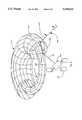
- FIG. 6is an isometric illustration of a massively parallel network according to an embodiment of the invention, configured as nested tori.
- FIG. 1is a diagrammatical illustration of a massively parallel network architecture according to an embodiment of the present invention.
- One matrix 21Acomprises sixteen interconnected client nodes (CN).
- Another matrix 21Bcomprises sixteen resource nodes (RN).
- CNclient nodes
- RNresource nodes
- the illustrated four-by-four matricesare exemplary, and those with skill in the art will recognize that the matrix dimensions may vary. In many applications of massively parallel networks according to the present invention, the matrices will be much larger.
- each client node and resource nodeby a matrix location CN(x,y) and RN(x,y) where x is a row number and y is a column number.
- the row and column numbersare labeled by numbers in parentheses.
- node 15has a matrix position 21A(1,1) and node 16 has a matrix position 21A(1,2).
- node 17occupies position 21B(1,1).
- matrix 21Afunctions as a client array and matrix 21B functions as a resource array.
- the distinctionis by the nature of connections to the nodes in each array.
- the nodes in the client arrayconnect by communication links to client networks.
- Two such networks 23A and 23B having client stations such as stations 27are shown connected to node 15 and to node 18.
- These client networksmay be configured as any one of many local area network configurations known in the art, or remote network configurations implemented by such as telephone links. There are many known arrangements for connecting such client groups.
- each client station in the client arrayconnects to a client network. Also, there is no requirement that each client network be of the same form and nature.
- matrix 21Bfunctions as a resource array.
- Resource nodesare connected by communication link to resource devices.
- One such connection 25Alinks resource node 17 at position 21B(1,1) to a hub 26A leading to resources shown as generic disk drives 28.
- a similar connection 25Bis shown linking resource node 14 at position 21B(1,4) to a hub 26B connected to other generic resources 28.
- each resource nodeis linked to a single resource, and in a full implementation, each resource node may be connected to a hub connecting several resources.
- the system in this embodimentis massively parallel by virtue of the communication links between nodes.
- the nodes in each row in each array in this exampleare connected serially in a ring.
- node (1,1)is linked to node (1,2), which is linked to node (1,3), which is linked in turn to node (1,4).
- Node (1,4)is linked back to node (1,1), so the four nodes are linked in a ring 22.
- nodes (2,1), (2,2), (2,3) and (2,4)are connected in ring 24, and so on.
- each columnis also serially ring connected in the same manner as described above for rows.
- nodes (1,1), (2,1), (3,1), and (4,1)are connected in ring 30.
- the nodes of column 2are ring connected in ring 32, and the nodes of column 3 and column 4 are similarly ring connected.
- each node in the resource arraybeing linked to each adjacent node in its row position and in its column position.
- each nodeis connected by communication link to four other nodes in the array.
- each client nodeis connected to a resource node.
- the connectionis by matrix position.
- client node 15 at position 21A(1,1)is linked to resource node 17 at position 21B(1,1) by link 19.
- a similar link(not shown) is established between 21A(1,2) and 21B(1,2), between 21A(1,3) and 21B(1,3), and so on.
- the communication flexibility of the system shownmay be illustrated by following a request for data from any client station 27 on network 23A linked to client node 15 at position 21A(1,1).
- the data requestis for data stored at a resource device 28 on link 25B connected to resource node 14 at position 21B(4,1).
- the data requestmay be routed via any one of five branches, each of four to an adjacent client node, or to resource node 17 at position 21B(1,1) via link 19.
- the requestis routed directly to the resource array via link 19, as might be preferable in a low-demand state.
- resource node 17there are four choices for routing, one link to each of the four adjacent resource nodes.
- the fifth link, to resources on link 25A,is not an option, because the request is for data available only on link 25B.
- the most direct route, assuming the next node is not busy,is directly from resource node 17 to resource node 14, which is an adjacent node in ring 30. In considering alternative routing, the very large number of choices is immediately apparent.
- FIG. 2Ais an isometric view of a massively parallel network system substantially according to the arrangement described above with reference to FIG. 1.
- System 31comprises two printed circuit boards (PCBs) 45 and 47, and each PCB comprises a matrix of integrated circuits (ICs) as nodes linked by communication links substantially as shown for the nodes of the arrays of FIG. 1.
- PCB 45is a client array and PCB 47 is a resource array.
- Each IC node on each PCBcomprises a microprocessor.
- PCB 45 in this embodimentcomprises 16 ICs in a 4 ⁇ 4 matrix
- PCB 47comprises 16 ICs in a 4 ⁇ 4 matrix, just as in FIG. 1.
- IC 41is located, for example, on client array PCB 45 at matrix position 45(4,2)
- IC 43is located on resource array 47 at matrix position 47(3,1).
- the PCBsare supported in a case 36, and each IC node on each PCB has a dedicated bus port with a connector positioned in a wall of case 36.
- IC 43, a resource node on PCB 47links to resource port 35 via resource bus 39.
- System 31may also comprises support circuitry for a conventional computerized system such as, but not limited to, a BIOS system and power supply. These elements are not shown in FIG. 2A.
- system 31also comprises circuitry to monitor each port for information management purposes such as determining the nature of the connection. For example, installed SCSI and/or Ethernet equipment. Also, it is not strictly required that there be a dedicated port for each IC node on both matrices. A lesser number of ports may be provided, with some ports serving more than a single node in the massively parallel architecture.
- FIG. 2Bis a largely diagrammatical isometric illustration of a portion of each of PCBs 45 and 47 in the embodiment shown in FIG. 2A.
- Client node 51 on PCB 45communicates via links 44 to the four adjacent nodes 48A, 48B, 48C and 48D.
- the links in one directionare a part of the row ring connection previously described, and the links in the other direction are a part of the column ring connection previously described.
- Resource node 53 on PCB 47communicates via links 46 to the four adjacent nodes 50A, 50B, 50C and 50D. Again the links in one direction are a part of the row ring connection previously described, and the links in the other direction are a part of the column ring connection previously described.
- Links 44 and 46, and other links between nodes not shownmay be any one of a wide variety of known communication connection types, including, but not limited to parallel, serial and optical digital and/or analog transmission links.
- the necessary hardware and firmware for managing the communication at each nodeis a part of the circuitry at each node, and depends on the nature of the links.
- the modulation and demodulation circuitry for converting digital data to and from the serial protocolis a part of the circuitry at each node.
- the nodesare described as single ICs, this structure is preferable and not required. each node could as well be implemented in two or more ICs with connective traces and structure.
- nodes 51 and 53are an associated pair in the matrix geometry (see description of matrices above). That is, nodes 51 and 53 have the same (x,y) address on different arrays. Accordingly, these two nodes are connected by another communication link 42. Moreover, a client LAN 55 is connected to client node 51, and a resource link 57 is connected to resource node 53. Similar links, not shown, are made to the other resource nodes and client nodes in FIG. 2B. Although it is not required, in the preferred embodiment described, arrangement of the nodes in square matrix arrays on PCBs, and alignment of the PCBs, brings associated nodes in proximity for connection.
- FIG. 3is a block diagram plan view of client node 51 according to a preferred embodiment of the present invention.
- the same drawingmay represent resource node 53 and other nodes in either matrix.
- a nodeis a client node or a resource node by nature of connection to resources or clients, rather than by particular physical structure.
- Node 51comprises a CPU 81, a memory unit 83 and routing bridge circuitry 85.
- the memory unitis random access memory (RAM). It will be apparent to those with skill in the art that other types of electronic memory may be used as well.
- Control routines stored in memory 83are accessed and operated by CPU 81 to manage data flow and logical functions for the local node. Outputs from CPU 81 configure bridge circuitry 85 for routing requests and data in the network. In node 41, CPU 81 is linked to RAM 83 by bus 87 and to bridge 85 by bus 89. A third bus 88 in this embodiment links bridge circuitry 85 with memory 83. In one embodiment, bus 88 has an extra wide bandwidth.
- Links 44are links to adjacent nodes on the same PCB as described above.
- Link 55is the link to a client LAN in this example via an outside connector
- link 57is the link to an associated node in the resource array. In the case of a resource node, link 57 would be the link to a resource or a resource hub.
- An advantage of RAM at each nodeis that control routines may be accessed and updated, and orchestrated from outside computer equipment to provide for optimum operation.
- An important purpose of the massively parallel architectureis to provide resources from numerous points to client at numerous other points while minimizing delay and maximizing data flow rate. This is accomplished by providing a very large number of alternative paths (massive interconnection) for requests and data, and by providing intelligent nodes for routing the data and requests through the massively parallel architecture in an efficient manner.
- each nodehas a microprocessor, thus machine intelligence, together with stored instructions and information for accomplishing efficient routing. It will be apparent to one with skill in the art that there are many alternative schemes for routing that may be used, and that the control routines might take any of a large number of forms.
- each nodeis provided with a map of clients and resources, detailing to which nodes the clients and resources directly connect. Moreover, in this embodiment, each node is "aware" of its own position in the network architecture.
- the essential nature of much information to be routed through such a networkis analog.
- such networksare useful for routing television (video) programs from storage (resources) to clients on a network.
- the essential nature of the network and the nodesis digital.
- datamay be transmitted between nodes, such as parallel bus and serial link, the data is managed digitally at each node.
- FIG. 4is a two-dimensional slice through a massively parallel network in an embodiment of the present invention, dedicated to providing TV movies to clients.
- the same diagrammay represent a massively parallel network for many other applications.
- Ring 119represents a portion of a client array
- ring 121represents a portion of a resource array.
- the portion represented, in the terms of the above descriptions,could be either a single row or a single column in each array. Connections in each array in the third dimension are not shown for simplicity.
- client nodesare labeled C1, C2, . . . C7
- resource nodesare labeled R1, R2, . . . R7
- a client network 123is connected to client node C5 and has a client 125 as a station on the network.
- a resourceis represented as a hard-disk drive 127 connected to resource node R6.
- other client networksmay be connected to the client nodes C1-C7, and other client nodes not shown.
- Separate resources and clientscan be connected in network fashion to nodes preferably only up to the ability of the transmission protocol on the client networks and resource branches to handle full load transfer without delay.
- client 125requests a movie stored at resource disk 127.
- Each client stationhas digital intelligence substantially configured like the node illustrated in FIG. 3, and described above. That is, each station has a microprocessor, a memory, sending and receiving circuitry for the client network, and control routines executable by the microprocessor to compose and transmit requests and to receive and process requested data.
- Client 125has a schedule of movies available, and an input apparatus for making a selection.
- the digital system at the client stationmay consult a lookup table and assign a resource code to the transmission, or all selection transmissions may be sent to an account manager.
- One or more of the resource nodes, or even client nodes,may be assigned the task of account managing for the system.
- resource node R4is account manager 129.
- the account managerhas control routines for accounting and scheduling in addition to routing routines, and has location information for clients and resources on the massively parallel network.
- all the resources and clientsare mapped at the single manager, and regular maintenance updates for changes in resources and clients (new clients subscribe, some discontinue the service, new movies become available, older movies may be discontinued).
- the clientmakes a selection, and the client station codes the data and transmits it on the client LAN to client node C5.
- the coded dataincludes one or more bits addressing the account manager, one or more bits identifying the client, and bits identifying the movie title requested. There may be other information, such as a particular time for transmission, or special information pertaining to charges, etc.
- the general process at client node C5, and at other nodes as well,is that incoming transmissions are immediately stored in the node memory, along with priority association for re-transmission. Beyond C5 there is a wide choice of available paths to account manager 129.
- the necessary intelligence for routingis stored at each client and resource node. For example, from C5, there are two apparently equal "best choices" to R4 (account manager 129). One is to R5, then to R4. The other is to C4, then to R4. There may be some reason in particular implementations why one of these two choices is "best", in which case that path will carry the first priority. If there is no such, one or the other may be first priority arbitrarily.
- the means of routingis "run and shoot"; that is, the node having data for retransmission has test routines for testing the available alternatives by priority, and, on finding a path open, passes the transmission on to a next node.
- the destination codedetermines which of five connections (three are shown) is on the shortest, or best, path, and the CPU tests that connection. If the node at the other end is not busy, the request is immediately retransmitted and deleted from memory.
- R5-R4is the highest priority path from C5 to R4, the CPU at C5 will first poll R5. If R5 is available, retransmission takes place; if it is not, the next node in priority is tested, and so forth, until the stored data for retransmission, in this case, client 125's request for a movie, is sent on.
- each requestis a short burst, typically a single data word of 16 or 32 bits, requiring only a very short transmission duration.
- transmission of informationlike a movie, the situation is somewhat different, as is described in more detail below.
- routingmay be prioritized and determined. Substantially all are based on priority and testing of some sort.
- client 125's request for a moviearrives at account manager 129, the request is processed. Client 125's account is charged for the particular movie time requested, and the updated account is then available for whatever billing cycle is in use.
- the account manageralso associates the material (movie) requested with the resource location, and initiates the process of sending the movie data to client 125's station.
- the transmission of a command packet issued by the account manager to resource 127 via resource node R6 to cause the requested movie data to be transmitted to client 125is similar to the transmission of the original request from client 125 to the account manager.
- the necessary information packetis rather small, requiring such as destination (node R6), movie ID on resource 127, time of transmission, and so forth.
- the routing of this command packetis accomplished by priority and testing, as described above. At R6 the command packet is stored and processed.
- FIG. 5represents the total data length of a movie in transfer time of length DS.
- the total data stringis stored in sectors, each providing, when processed, for example, 1 minute of viewing time of the movie.
- a movie of three hours lengththen, would be stored and processed in 180 sectors S1, S2 . . . , S180.
- Initial sectors S1, S2, S3, S4,are indicated in FIG. 5.
- Each sectoralthough it represents a full minute of viewing time, can be transmitted in perhaps milliseconds as digital data from node to node in the massively parallel network, depending on the characteristics of the data paths and modes of transmission.
- Node R6having received the command packet from the account manager, executes the commands according to stored control routines.
- Node R6retrieves a first sector (S1), stores that sector in its local memory, and transmits it on toward client 125 in the same manner as described above for routing requests and command packets.
- R6continues to retrieve, store, and delete until it has sent along all of the sectors for the movie, after which it may (or may not) issue an acknowledgement to the account manager, depending on the vagaries of the particular protocol and application.
- each nodehas as many as four connections in the same array (resource or client), and one each to the opposite array, and either a resource trunk or a client LAN connection, there is no guarantee that consecutive sectors will follow a common path from resource 127 to client 125. Unless the loading is low, it is not likely. There is no need, however, for all of the sectors of the movie to follow one another in sequential fashion or even to arrive in order.
- Each sector transmitted through the maze of the massively parallel networkis coded (sector #, destination, etc.), and as each sector arrives at client LAN station 125, it is recorded in memory according to prearranged addresses.
- the moviemay begin, by converting the available data to video signals and transmitting the signals to the TV display. In most cases this is a CRT video tube, but that is not a requirement.
- LCDliquid crystal display
- ELDelectrowetting diode
- FIG. 6is a massively parallel network according to an embodiment of the invention wherein the resource array and the client array are configured as nested tori.
- the outer torusis a client array 11 and the inner torus is a resource array 13.
- Each intersection on client array 11 and resource array 13is a node in the massively parallel network.
- the position of the client array and resource arraymay be reversed.
- the torus representation geometricallyis equivalent to matrix array like that presented in FIG. 1.
- FIG. 6is meant to illustrate the toroidal nature of the interconnecting geometry, ad no attempt has been made to match nodes by position or number.
- FIG. 6a portion of the outer torus (client array) is shown cut away to illustrate the inner torus (resource array).
- a single client node 101is shown connected to a single resource node 103 and to a client LAN 107 having at least one client station 108.
- Each client nodeis connected in two rings, one around the major diameter of the torus, and the other around the minor diameter, as is each resource node on the opposite torus array.
- Resource node 103is connected to a resource hub 109 having at least one resource 110.
- the nested torus arrangementis illustrative and not limiting.
- the same connectivityis illustrated in the matrix arrays of FIG. 1, wherein the node at the end of each row is connected back to the first node in the row, and the node at the bottom of each column is connected back to the node at the top of the column.
- the toriare configured as PCBs locally to fit inside a case 111 similar to the case illustrated and described with reference to FIG. 2A.
- Case 111would have the required number of I/O ports equal to the total number of client nodes and resource nodes.
- the massively parallel network architecturemay be applied as a large transaction system in real time.
- a banking systemmay be implemented by allocating client nodes to different local bank branches with dedicated communication trunks to tellers' workstations and ATM machines. ATM limits could be relaxed because each customer's balance may be updated quickly throughout the system.
- Massively parallel network architectureallows for flexibility in data resource configuration and allows for a large number of branch banks to maintain current transaction status.
- the resource array and the client arraymight both be local, perhaps as shown in FIG. 2A, or in some other local arrangement.
- therwould be communication trunks from the local client nodes going to the different branch or ATM locations.
- the client nodesmight be remotely located at the branch or ATM.
- massively parallel network architecturecould manage large data flow in a paperless company.
- a large businessmay have as many as 100 fax lines, each capable of generating a page of fax containing approximately 30 kilobits about every fifteen seconds.
- some client nodesmay service several users' fax requests and some resource nodes may be dedicated to fax modems, attached telephone lines and media storage devices for storing faxes.
- a businesscan effectively manage fax flow, reducing the need for a large number of fax machines and telephone lines.
- a massively parallel systemmay be re-configured at times of system expansion.
- a system-wide hashing control routinecould redistribute resource locations according to results of tracked transactions to provide for optimal performance.
- massively parallel network architecture according to the inventioncan provide effective, real-time access for a large number of users.
- microprocessors of many sorts and manufacturemay be used.
- the variability of programmed control routinesis very great, and the means of prioritizing and routing is similarly variable within the spirit and scope of the invention.
Landscapes
- Engineering & Computer Science (AREA)
- Signal Processing (AREA)
- Multimedia (AREA)
- Computer Networks & Wireless Communication (AREA)
- General Engineering & Computer Science (AREA)
- Theoretical Computer Science (AREA)
- Computer Hardware Design (AREA)
- Physics & Mathematics (AREA)
- General Physics & Mathematics (AREA)
- Multi Processors (AREA)
- Computer And Data Communications (AREA)
Abstract
Description
Claims (7)
Priority Applications (1)
| Application Number | Priority Date | Filing Date | Title |
|---|---|---|---|
| US08/493,917US5539621A (en) | 1994-01-14 | 1995-06-23 | Network communication unit with client and resource node array double layer ICs on printed board with connectors on housing |
Applications Claiming Priority (2)
| Application Number | Priority Date | Filing Date | Title |
|---|---|---|---|
| US08/182,282US5515510A (en) | 1994-01-14 | 1994-01-14 | Communications internetwork system connecting a client node array to a resource array |
| US08/493,917US5539621A (en) | 1994-01-14 | 1995-06-23 | Network communication unit with client and resource node array double layer ICs on printed board with connectors on housing |
Related Parent Applications (1)
| Application Number | Title | Priority Date | Filing Date |
|---|---|---|---|
| US08/182,282DivisionUS5515510A (en) | 1994-01-14 | 1994-01-14 | Communications internetwork system connecting a client node array to a resource array |
Publications (1)
| Publication Number | Publication Date |
|---|---|
| US5539621Atrue US5539621A (en) | 1996-07-23 |
Family
ID=22667800
Family Applications (2)
| Application Number | Title | Priority Date | Filing Date |
|---|---|---|---|
| US08/182,282Expired - LifetimeUS5515510A (en) | 1994-01-14 | 1994-01-14 | Communications internetwork system connecting a client node array to a resource array |
| US08/493,917Expired - Fee RelatedUS5539621A (en) | 1994-01-14 | 1995-06-23 | Network communication unit with client and resource node array double layer ICs on printed board with connectors on housing |
Family Applications Before (1)
| Application Number | Title | Priority Date | Filing Date |
|---|---|---|---|
| US08/182,282Expired - LifetimeUS5515510A (en) | 1994-01-14 | 1994-01-14 | Communications internetwork system connecting a client node array to a resource array |
Country Status (2)
| Country | Link |
|---|---|
| US (2) | US5515510A (en) |
| WO (1) | WO1995019673A1 (en) |
Cited By (22)
| Publication number | Priority date | Publication date | Assignee | Title |
|---|---|---|---|---|
| US5703759A (en)* | 1995-12-07 | 1997-12-30 | Xilinx, Inc. | Multi-chip electrically reconfigurable module with predominantly extra-package inter-chip connections |
| US5892932A (en)* | 1995-11-21 | 1999-04-06 | Fore Systems, Inc. | Reprogrammable switching apparatus and method |
| US5898827A (en)* | 1996-09-27 | 1999-04-27 | Hewlett-Packard Co. | Routing methods for a multinode SCI computer system |
| US5913028A (en)* | 1995-10-06 | 1999-06-15 | Xpoint Technologies, Inc. | Client/server data traffic delivery system and method |
| US5918021A (en)* | 1996-06-03 | 1999-06-29 | Intel Corporation | System and method for dynamic distribution of data packets through multiple channels |
| US5991809A (en)* | 1996-07-25 | 1999-11-23 | Clearway Technologies, Llc | Web serving system that coordinates multiple servers to optimize file transfers |
| US6167477A (en)* | 1998-06-15 | 2000-12-26 | Sun Microsystems, Inc. | Computer system bridge employing a resource control mechanism with programmable registers to control resource allocation |
| US6185598B1 (en) | 1998-02-10 | 2001-02-06 | Digital Island, Inc. | Optimized network resource location |
| US6490725B2 (en) | 1994-01-14 | 2002-12-03 | Elonex I.P. Holdings, Ltd. | Transmitting notification of new video clips of interest from servers in wide area network |
| US7054935B2 (en) | 1998-02-10 | 2006-05-30 | Savvis Communications Corporation | Internet content delivery network |
| US20080065544A1 (en)* | 1996-05-10 | 2008-03-13 | Barcelou David M | Automated transaction machine |
| US7373644B2 (en) | 2001-10-02 | 2008-05-13 | Level 3 Communications, Llc | Automated server replication |
| US7822871B2 (en) | 2001-09-28 | 2010-10-26 | Level 3 Communications, Llc | Configurable adaptive global traffic control and management |
| US7860964B2 (en) | 2001-09-28 | 2010-12-28 | Level 3 Communications, Llc | Policy-based content delivery network selection |
| US7949779B2 (en) | 1998-02-10 | 2011-05-24 | Level 3 Communications, Llc | Controlling subscriber information rates in a content delivery network |
| US7953888B2 (en) | 1999-06-18 | 2011-05-31 | Level 3 Communications, Llc | On-demand overlay routing for computer-based communication networks |
| US8543901B1 (en) | 1999-11-01 | 2013-09-24 | Level 3 Communications, Llc | Verification of content stored in a network |
| US8924466B2 (en) | 2002-02-14 | 2014-12-30 | Level 3 Communications, Llc | Server handoff in content delivery network |
| US8930538B2 (en) | 2008-04-04 | 2015-01-06 | Level 3 Communications, Llc | Handling long-tail content in a content delivery network (CDN) |
| US9021112B2 (en) | 2001-10-18 | 2015-04-28 | Level 3 Communications, Llc | Content request routing and load balancing for content distribution networks |
| US9762692B2 (en) | 2008-04-04 | 2017-09-12 | Level 3 Communications, Llc | Handling long-tail content in a content delivery network (CDN) |
| US10924573B2 (en) | 2008-04-04 | 2021-02-16 | Level 3 Communications, Llc | Handling long-tail content in a content delivery network (CDN) |
Families Citing this family (28)
| Publication number | Priority date | Publication date | Assignee | Title |
|---|---|---|---|---|
| US5724517A (en)* | 1994-09-27 | 1998-03-03 | International Business Machines Corporation | Method for generating a topology map for a serial bus |
| JPH08223195A (en)* | 1994-11-22 | 1996-08-30 | At & T Corp | Local area hub network allowing expansion of port number andmethod of expanding its port number |
| US7035914B1 (en) | 1996-01-26 | 2006-04-25 | Simpleair Holdings, Inc. | System and method for transmission of data |
| US5818448A (en)* | 1996-07-02 | 1998-10-06 | Sun Microsystems, Inc. | Apparatus and method for identifying server computer aggregation topologies |
| KR100270354B1 (en)* | 1996-11-20 | 2000-11-01 | 정선종 | Relay server of heterogeneous manganese and real-time relay method |
| US6144992A (en)* | 1997-05-09 | 2000-11-07 | Altiris, Inc. | Method and system for client/server and peer-to-peer disk imaging |
| US7177867B2 (en)* | 2000-10-23 | 2007-02-13 | Sri International | Method and apparatus for providing scalable resource discovery |
| CN1311376C (en)* | 2001-02-24 | 2007-04-18 | 国际商业机器公司 | Novel massively parallel super computer |
| US7266596B2 (en)* | 2001-04-18 | 2007-09-04 | International Business Machines Corporation | Dynamic storage space linking |
| US20020191601A1 (en)* | 2001-06-15 | 2002-12-19 | Alcatel, Societe Anonyme | On-chip communication architecture and method |
| US7027413B2 (en)* | 2001-09-28 | 2006-04-11 | Sun Microsystems, Inc. | Discovery of nodes in an interconnection fabric |
| US20050076336A1 (en)* | 2003-10-03 | 2005-04-07 | Nortel Networks Limited | Method and apparatus for scheduling resources on a switched underlay network |
| US9386327B2 (en)* | 2006-05-24 | 2016-07-05 | Time Warner Cable Enterprises Llc | Secondary content insertion apparatus and methods |
| US8280982B2 (en) | 2006-05-24 | 2012-10-02 | Time Warner Cable Inc. | Personal content server apparatus and methods |
| US8024762B2 (en) | 2006-06-13 | 2011-09-20 | Time Warner Cable Inc. | Methods and apparatus for providing virtual content over a network |
| US8352302B2 (en)* | 2007-07-17 | 2013-01-08 | At&T Intellectual Property I, L.P. | Methods, systems, and computer-readable media for determining a plurality of turfs from where to reallocate a workforce to a given turf |
| US8341547B2 (en)* | 2007-07-17 | 2012-12-25 | At&T Intellectual Property I, L.P. | Methods, systems, and computer-readable media for providing contact information at turf level |
| US8069072B2 (en)* | 2007-07-17 | 2011-11-29 | At&T Intellectual Property I, Lp | Methods, systems, and computer-readable media for providing an indication of hightime |
| US20090024438A1 (en)* | 2007-07-17 | 2009-01-22 | Robert Ingman | Methods, Systems, and Computer-Readable Media for Providing Workforce To Load Information |
| US8060401B2 (en)* | 2007-07-17 | 2011-11-15 | At&T Intellectual Property I, Lp | Methods, systems, and computer-readable media for providing an indication of a schedule conflict |
| US8380744B2 (en)* | 2007-07-17 | 2013-02-19 | At&T Intellectual Property I, L.P. | Methods, systems, and computer-readable media for generating a report indicating job availability |
| US8239232B2 (en) | 2007-07-17 | 2012-08-07 | At&T Intellectual Property I, L.P. | Methods, systems, and computer-readable media for providing commitments information relative to a turf |
| US20090024437A1 (en)* | 2007-07-17 | 2009-01-22 | Robert Ingman | Methods, Systems, and Computer-Readable Media for Providing A Ratio of Tasks Per Technician |
| US8249905B2 (en)* | 2007-07-17 | 2012-08-21 | At&T Intellectual Property I, Lp | Methods, systems, and computer-readable media for providing future job information |
| US20110264530A1 (en) | 2010-04-23 | 2011-10-27 | Bryan Santangelo | Apparatus and methods for dynamic secondary content and data insertion and delivery |
| US20140282786A1 (en) | 2013-03-12 | 2014-09-18 | Time Warner Cable Enterprises Llc | Methods and apparatus for providing and uploading content to personalized network storage |
| US10586023B2 (en) | 2016-04-21 | 2020-03-10 | Time Warner Cable Enterprises Llc | Methods and apparatus for secondary content management and fraud prevention |
| US11403849B2 (en) | 2019-09-25 | 2022-08-02 | Charter Communications Operating, Llc | Methods and apparatus for characterization of digital content |
Citations (6)
| Publication number | Priority date | Publication date | Assignee | Title |
|---|---|---|---|---|
| US4672373A (en)* | 1983-12-23 | 1987-06-09 | Hitachi, Ltd. | Communication network system |
| US4830623A (en)* | 1988-02-10 | 1989-05-16 | Rogers Corporation | Connector arrangement for electrically interconnecting first and second arrays of pad-type contacts |
| US5175733A (en)* | 1990-12-27 | 1992-12-29 | Intel Corporation | Adaptive message routing for multi-dimensional networks |
| US5341504A (en)* | 1983-12-28 | 1994-08-23 | Hitachi, Ltd. | Multi-dimensional structured computer system |
| US5426563A (en)* | 1992-08-05 | 1995-06-20 | Fujitsu Limited | Three-dimensional multichip module |
| US5495397A (en)* | 1993-04-27 | 1996-02-27 | International Business Machines Corporation | Three dimensional package and architecture for high performance computer |
Family Cites Families (6)
| Publication number | Priority date | Publication date | Assignee | Title |
|---|---|---|---|---|
| JPS5544429B2 (en)* | 1973-05-11 | 1980-11-12 | ||
| US4901205A (en)* | 1988-09-02 | 1990-02-13 | Ncr Corporation | Housing for electronic components |
| US5167035A (en)* | 1988-09-08 | 1992-11-24 | Digital Equipment Corporation | Transferring messages between nodes in a network |
| US5134690A (en)* | 1989-06-26 | 1992-07-28 | Samatham Maheswara R | Augumented multiprocessor networks |
| US4991000A (en)* | 1989-08-31 | 1991-02-05 | Bone Robert L | Vertically interconnected integrated circuit chip system |
| ES2028554A6 (en)* | 1990-11-05 | 1992-07-01 | Telefonica Nacional Espana Co | Telecommunications packet switching system |
- 1994
- 1994-01-14USUS08/182,282patent/US5515510A/ennot_activeExpired - Lifetime
- 1995
- 1995-01-13WOPCT/US1995/000672patent/WO1995019673A1/enactiveApplication Filing
- 1995-06-23USUS08/493,917patent/US5539621A/ennot_activeExpired - Fee Related
Patent Citations (6)
| Publication number | Priority date | Publication date | Assignee | Title |
|---|---|---|---|---|
| US4672373A (en)* | 1983-12-23 | 1987-06-09 | Hitachi, Ltd. | Communication network system |
| US5341504A (en)* | 1983-12-28 | 1994-08-23 | Hitachi, Ltd. | Multi-dimensional structured computer system |
| US4830623A (en)* | 1988-02-10 | 1989-05-16 | Rogers Corporation | Connector arrangement for electrically interconnecting first and second arrays of pad-type contacts |
| US5175733A (en)* | 1990-12-27 | 1992-12-29 | Intel Corporation | Adaptive message routing for multi-dimensional networks |
| US5426563A (en)* | 1992-08-05 | 1995-06-20 | Fujitsu Limited | Three-dimensional multichip module |
| US5495397A (en)* | 1993-04-27 | 1996-02-27 | International Business Machines Corporation | Three dimensional package and architecture for high performance computer |
Cited By (69)
| Publication number | Priority date | Publication date | Assignee | Title |
|---|---|---|---|---|
| US6490725B2 (en) | 1994-01-14 | 2002-12-03 | Elonex I.P. Holdings, Ltd. | Transmitting notification of new video clips of interest from servers in wide area network |
| US5913028A (en)* | 1995-10-06 | 1999-06-15 | Xpoint Technologies, Inc. | Client/server data traffic delivery system and method |
| US5892932A (en)* | 1995-11-21 | 1999-04-06 | Fore Systems, Inc. | Reprogrammable switching apparatus and method |
| US5703759A (en)* | 1995-12-07 | 1997-12-30 | Xilinx, Inc. | Multi-chip electrically reconfigurable module with predominantly extra-package inter-chip connections |
| US8600887B2 (en) | 1996-05-10 | 2013-12-03 | Transaction Holdings Ltd., Llc | Automated transaction machine |
| US8632007B2 (en) | 1996-05-10 | 2014-01-21 | Transaction Holdings Ltd., Llc | Automated transaction machine |
| US8708231B2 (en) | 1996-05-10 | 2014-04-29 | Transaction Holdings Ltd, LLC | Automated transaction machine |
| US8600890B2 (en) | 1996-05-10 | 2013-12-03 | Transaction Holdings Ltd., Llc | Automated transaction machine |
| US8600889B2 (en) | 1996-05-10 | 2013-12-03 | Transaction Holdings Ltd. Llc | Automated transaction machine |
| US8600888B2 (en) | 1996-05-10 | 2013-12-03 | Transaction Holdings Ltd., Llc | Automated transaction machine |
| US8583522B2 (en) | 1996-05-10 | 2013-11-12 | Transaction Holdings Ltd., Llc | Automated transaction machine |
| US8571952B2 (en) | 1996-05-10 | 2013-10-29 | Transaction Holdings Ltd., Llc | Automated transaction machine |
| US8560451B2 (en) | 1996-05-10 | 2013-10-15 | Transaction Holdings Ltd., Llc | Automated transaction machine |
| US8554677B2 (en) | 1996-05-10 | 2013-10-08 | Transaction Holdings Ltd., Llc | Automated transaction machine |
| US8543507B2 (en) | 1996-05-10 | 2013-09-24 | Transactions Holdings Ltd., LLC | Automated transaction machine |
| US20080067235A1 (en)* | 1996-05-10 | 2008-03-20 | Barcelou David M | Automated transaction machine |
| US20080065545A1 (en)* | 1996-05-10 | 2008-03-13 | Barcelou David M | Automated transaction machine |
| US20080065544A1 (en)* | 1996-05-10 | 2008-03-13 | Barcelou David M | Automated transaction machine |
| US20080061131A1 (en)* | 1996-05-10 | 2008-03-13 | Barcelou David M | Automated transaction machine |
| US20080065543A1 (en)* | 1996-05-10 | 2008-03-13 | Barcelou David M | Automated transaction machine |
| US20080065539A1 (en)* | 1996-05-10 | 2008-03-13 | Barcelou David M | Automated transaction machine |
| US20080065542A1 (en)* | 1996-05-10 | 2008-03-13 | Barcelou David M | Automated transaction machine |
| US20080065536A1 (en)* | 1996-05-10 | 2008-03-13 | Barcelou David M | Automated transaction machine |
| US20080065541A1 (en)* | 1996-05-10 | 2008-03-13 | Barcelou David M | Automated transaction machine |
| US5918021A (en)* | 1996-06-03 | 1999-06-29 | Intel Corporation | System and method for dynamic distribution of data packets through multiple channels |
| US6718393B1 (en) | 1996-06-03 | 2004-04-06 | Intel Corporation | System and method for dynamic distribution of data traffic load through multiple channels |
| US5991809A (en)* | 1996-07-25 | 1999-11-23 | Clearway Technologies, Llc | Web serving system that coordinates multiple servers to optimize file transfers |
| US6915329B2 (en) | 1996-07-25 | 2005-07-05 | Xcelera | Web serving system |
| US6480893B2 (en) | 1996-07-25 | 2002-11-12 | Clearway Acquisition, Inc. | Web serving system |
| US6370580B2 (en) | 1996-07-25 | 2002-04-09 | Clearway Acquisition, Inc. | Web serving system that coordinates multiple servers to optimize file transfers |
| US20050038851A1 (en)* | 1996-07-25 | 2005-02-17 | Xcelera, A Delaware Corporation | Web serving system |
| US8019869B2 (en) | 1996-07-25 | 2011-09-13 | Xcelera Inc. | Web serving system |
| US5898827A (en)* | 1996-09-27 | 1999-04-27 | Hewlett-Packard Co. | Routing methods for a multinode SCI computer system |
| US8296396B2 (en) | 1998-02-10 | 2012-10-23 | Level 3 Communications, Llc | Delivering resources to clients in a distributed computing environment with rendezvous based on load balancing and network conditions |
| US8281035B2 (en) | 1998-02-10 | 2012-10-02 | Level 3 Communications, Llc | Optimized network resource location |
| US8291046B2 (en) | 1998-02-10 | 2012-10-16 | Level 3 Communications, Llc | Shared content delivery infrastructure with rendezvous based on load balancing and network conditions |
| US8060613B2 (en) | 1998-02-10 | 2011-11-15 | Level 3 Communications, Llc | Resource invalidation in a content delivery network |
| US8468245B2 (en) | 1998-02-10 | 2013-06-18 | Level 3 Communications, Llc | Delivering resources to clients in a distributed computing environment |
| US8572210B2 (en) | 1998-02-10 | 2013-10-29 | Level 3 Communications, Llc | Shared content delivery infrastructure and method of generating a web page |
| US8478903B2 (en) | 1998-02-10 | 2013-07-02 | Level 3 Communications, Llc | Shared content delivery infrastructure |
| US8683076B2 (en) | 1998-02-10 | 2014-03-25 | Level 3 Communications, Llc | Method of generating a web page |
| US8473613B2 (en) | 1998-02-10 | 2013-06-25 | Level 3 Communications, Llc | Transparent redirection of resource requests |
| US7949779B2 (en) | 1998-02-10 | 2011-05-24 | Level 3 Communications, Llc | Controlling subscriber information rates in a content delivery network |
| US6654807B2 (en) | 1998-02-10 | 2003-11-25 | Cable & Wireless Internet Services, Inc. | Internet content delivery network |
| US7945693B2 (en) | 1998-02-10 | 2011-05-17 | Level 3 Communications, Llc | Controlling subscriber information rates in a content delivery network |
| US7054935B2 (en) | 1998-02-10 | 2006-05-30 | Savvis Communications Corporation | Internet content delivery network |
| US8572208B2 (en) | 1998-02-10 | 2013-10-29 | Level 3 Communications, Llc | Shared content delivery infrastructure |
| US6185598B1 (en) | 1998-02-10 | 2001-02-06 | Digital Island, Inc. | Optimized network resource location |
| WO1999066416A3 (en)* | 1998-06-15 | 2001-12-13 | Sun Microsystems Inc | Resource control in a computer system |
| US6167477A (en)* | 1998-06-15 | 2000-12-26 | Sun Microsystems, Inc. | Computer system bridge employing a resource control mechanism with programmable registers to control resource allocation |
| US8599697B2 (en) | 1999-06-18 | 2013-12-03 | Level 3 Communications, Llc | Overlay network |
| US7953888B2 (en) | 1999-06-18 | 2011-05-31 | Level 3 Communications, Llc | On-demand overlay routing for computer-based communication networks |
| US8543901B1 (en) | 1999-11-01 | 2013-09-24 | Level 3 Communications, Llc | Verification of content stored in a network |
| US7822871B2 (en) | 2001-09-28 | 2010-10-26 | Level 3 Communications, Llc | Configurable adaptive global traffic control and management |
| US9203636B2 (en) | 2001-09-28 | 2015-12-01 | Level 3 Communications, Llc | Distributing requests across multiple content delivery networks based on subscriber policy |
| US8645517B2 (en) | 2001-09-28 | 2014-02-04 | Level 3 Communications, Llc | Policy-based content delivery network selection |
| US7860964B2 (en) | 2001-09-28 | 2010-12-28 | Level 3 Communications, Llc | Policy-based content delivery network selection |
| US7373644B2 (en) | 2001-10-02 | 2008-05-13 | Level 3 Communications, Llc | Automated server replication |
| US10771541B2 (en) | 2001-10-02 | 2020-09-08 | Level 3 Communications, Llc | Automated management of content servers based on change in demand |
| US9338227B2 (en) | 2001-10-02 | 2016-05-10 | Level 3 Communications, Llc | Automated management of content servers based on change in demand |
| US9021112B2 (en) | 2001-10-18 | 2015-04-28 | Level 3 Communications, Llc | Content request routing and load balancing for content distribution networks |
| US9167036B2 (en) | 2002-02-14 | 2015-10-20 | Level 3 Communications, Llc | Managed object replication and delivery |
| US9992279B2 (en) | 2002-02-14 | 2018-06-05 | Level 3 Communications, Llc | Managed object replication and delivery |
| US8924466B2 (en) | 2002-02-14 | 2014-12-30 | Level 3 Communications, Llc | Server handoff in content delivery network |
| US10979499B2 (en) | 2002-02-14 | 2021-04-13 | Level 3 Communications, Llc | Managed object replication and delivery |
| US8930538B2 (en) | 2008-04-04 | 2015-01-06 | Level 3 Communications, Llc | Handling long-tail content in a content delivery network (CDN) |
| US9762692B2 (en) | 2008-04-04 | 2017-09-12 | Level 3 Communications, Llc | Handling long-tail content in a content delivery network (CDN) |
| US10218806B2 (en) | 2008-04-04 | 2019-02-26 | Level 3 Communications, Llc | Handling long-tail content in a content delivery network (CDN) |
| US10924573B2 (en) | 2008-04-04 | 2021-02-16 | Level 3 Communications, Llc | Handling long-tail content in a content delivery network (CDN) |
Also Published As
| Publication number | Publication date |
|---|---|
| WO1995019673A1 (en) | 1995-07-20 |
| US5515510A (en) | 1996-05-07 |
Similar Documents
| Publication | Publication Date | Title |
|---|---|---|
| US5539621A (en) | Network communication unit with client and resource node array double layer ICs on printed board with connectors on housing | |
| US6163795A (en) | Server for notifying items of interest and delivering locally accessed video in a WAN to client stations on demand | |
| US7661019B2 (en) | Method and apparatus for seamless management for disaster recovery | |
| US5602991A (en) | System for managing system for managing networked computer applications | |
| US6061349A (en) | System and method for implementing multiple IP addresses on multiple ports | |
| US20020040389A1 (en) | System and method for remotely-managed content distribution network | |
| RU96116124A (en) | DEVICE FOR MANAGING NETWORKED COMPUTER SYSTEMS AND METHOD FOR ITS IMPLEMENTATION | |
| Pierce | How far can data loops go? | |
| US20050154841A1 (en) | Data storage system for a multi-client network and method of managing such system | |
| US20030079016A1 (en) | Using NAS appliance to build a non-conventional distributed video server | |
| US20030194073A1 (en) | Telecommunication resource allocation system and method | |
| WO2000002365A1 (en) | Systems and methods for utilizing a communications network for providing mobile users access to legacy systems | |
| Sundstrom et al. | SNA: Current requirements and direction | |
| FI108594B (en) | A method for routing information within a telephone network access control network | |
| JP2638441B2 (en) | Relay file transfer method | |
| Malabarba | WHY A DATA BASE MACHINE? | |
| EP1413113B1 (en) | Routing of peer-to-peer messages in a communication network | |
| KR100650003B1 (en) | Data communication load balancing control program and data load balancing control method | |
| JPH06152615A (en) | Data transfer method in local area network having plural transmission lines | |
| JP3025126B2 (en) | Network line setting information management method | |
| Antenucci et al. | System Configurations and Data Communications | |
| Hunt et al. | Movements Information Network (MINET) Testbed Design Study | |
| JPH0591130A (en) | Mail transfer system in host interlocking type facsimile store and forward exchange system | |
| JPH04269051A (en) | System for setting plural lines | |
| IES970203A2 (en) | A transaction processing system |
Legal Events
| Date | Code | Title | Description |
|---|---|---|---|
| AS | Assignment | Owner name:ELONEX IP HOLDINGS LTD., ENGLAND Free format text:ASSIGNMENT OF ASSIGNORS INTEREST;ASSIGNOR:ELONEX TECHNOLOGIES, INC.;REEL/FRAME:007934/0541 Effective date:19960501 Owner name:ELONEX TECHNOLOGIES, INC., CALIFORNIA Free format text:ASSIGNMENT OF ASSIGNORS INTEREST;ASSIGNOR:KIKINIS, DAN;REEL/FRAME:007934/0263 Effective date:19960110 | |
| FEPP | Fee payment procedure | Free format text:PAT HLDR NO LONGER CLAIMS SMALL ENT STAT AS SMALL BUSINESS (ORIGINAL EVENT CODE: LSM2); ENTITY STATUS OF PATENT OWNER: LARGE ENTITY | |
| FPAY | Fee payment | Year of fee payment:4 | |
| REMI | Maintenance fee reminder mailed | ||
| LAPS | Lapse for failure to pay maintenance fees | ||
| FP | Lapsed due to failure to pay maintenance fee | Effective date:20040723 | |
| AS | Assignment | Owner name:PDACO LTD., NOT PROVIDED Free format text:ASSIGNMENT OF ASSIGNORS INTEREST;ASSIGNOR:ELONEX IP HOLDINGS, LTD.;REEL/FRAME:019704/0349 Effective date:20070804 | |
| AS | Assignment | Owner name:ELONEX TECHNOLOGIES, INC., CALIFORNIA Free format text:CORRECTIVE ASSIGNMENT TO CORRECT THE 08/194,282 S/B 08/194,242 08/208,539 S/B 08/209,539 08/181,282 S/B 08/182,282 08/419,022 S/B 08/419,021 PREVIOUSLY RECORDED ON REEL 007934 FRAME 0263. ASSIGNOR(S) HEREBY CONFIRMS THE INCORRECT APPLICATION NUMBERS: 08/194,282; 08/208,539; 08/181,282; 08/419,022(ALL OTHER APP. NO. ARE CORRECT);ASSIGNOR:KIKINIS, DAN;REEL/FRAME:025160/0958 Effective date:19960110 | |
| STCH | Information on status: patent discontinuation | Free format text:PATENT EXPIRED DUE TO NONPAYMENT OF MAINTENANCE FEES UNDER 37 CFR 1.362 |