US5539422A - Head mounted display system - Google Patents
Head mounted display systemDownload PDFInfo
- Publication number
- US5539422A US5539422AUS08/045,919US4591993AUS5539422AUS 5539422 AUS5539422 AUS 5539422AUS 4591993 AUS4591993 AUS 4591993AUS 5539422 AUS5539422 AUS 5539422A
- Authority
- US
- United States
- Prior art keywords
- display system
- optical element
- head mounted
- recited
- mounted display
- Prior art date
- Legal status (The legal status is an assumption and is not a legal conclusion. Google has not performed a legal analysis and makes no representation as to the accuracy of the status listed.)
- Expired - Fee Related
Links
Images


Classifications
- G—PHYSICS
- G02—OPTICS
- G02B—OPTICAL ELEMENTS, SYSTEMS OR APPARATUS
- G02B27/00—Optical systems or apparatus not provided for by any of the groups G02B1/00 - G02B26/00, G02B30/00
- G02B27/01—Head-up displays
- G02B27/017—Head mounted
- G02B27/0172—Head mounted characterised by optical features
- G—PHYSICS
- G02—OPTICS
- G02B—OPTICAL ELEMENTS, SYSTEMS OR APPARATUS
- G02B27/00—Optical systems or apparatus not provided for by any of the groups G02B1/00 - G02B26/00, G02B30/00
- G02B27/01—Head-up displays
- G02B27/017—Head mounted
- G02B27/0176—Head mounted characterised by mechanical features
- G—PHYSICS
- G02—OPTICS
- G02B—OPTICAL ELEMENTS, SYSTEMS OR APPARATUS
- G02B27/00—Optical systems or apparatus not provided for by any of the groups G02B1/00 - G02B26/00, G02B30/00
- G02B27/01—Head-up displays
- G02B27/0101—Head-up displays characterised by optical features
- G02B2027/011—Head-up displays characterised by optical features comprising device for correcting geometrical aberrations, distortion
- G—PHYSICS
- G02—OPTICS
- G02B—OPTICAL ELEMENTS, SYSTEMS OR APPARATUS
- G02B27/00—Optical systems or apparatus not provided for by any of the groups G02B1/00 - G02B26/00, G02B30/00
- G02B27/01—Head-up displays
- G02B27/0101—Head-up displays characterised by optical features
- G02B2027/0112—Head-up displays characterised by optical features comprising device for genereting colour display
- G02B2027/0116—Head-up displays characterised by optical features comprising device for genereting colour display comprising devices for correcting chromatic aberration
- G—PHYSICS
- G02—OPTICS
- G02B—OPTICAL ELEMENTS, SYSTEMS OR APPARATUS
- G02B27/00—Optical systems or apparatus not provided for by any of the groups G02B1/00 - G02B26/00, G02B30/00
- G02B27/01—Head-up displays
- G02B27/0101—Head-up displays characterised by optical features
- G02B2027/0143—Head-up displays characterised by optical features the two eyes not being equipped with identical nor symmetrical optical devices
- G—PHYSICS
- G02—OPTICS
- G02B—OPTICAL ELEMENTS, SYSTEMS OR APPARATUS
- G02B27/00—Optical systems or apparatus not provided for by any of the groups G02B1/00 - G02B26/00, G02B30/00
- G02B27/01—Head-up displays
- G02B27/0149—Head-up displays characterised by mechanical features
- G02B2027/0154—Head-up displays characterised by mechanical features with movable elements
- G02B2027/0158—Head-up displays characterised by mechanical features with movable elements with adjustable nose pad
- G—PHYSICS
- G02—OPTICS
- G02B—OPTICAL ELEMENTS, SYSTEMS OR APPARATUS
- G02B27/00—Optical systems or apparatus not provided for by any of the groups G02B1/00 - G02B26/00, G02B30/00
- G02B27/01—Head-up displays
- G02B27/0149—Head-up displays characterised by mechanical features
- G02B2027/0154—Head-up displays characterised by mechanical features with movable elements
- G02B2027/0159—Head-up displays characterised by mechanical features with movable elements with mechanical means other than scaning means for positioning the whole image
- G—PHYSICS
- G02—OPTICS
- G02B—OPTICAL ELEMENTS, SYSTEMS OR APPARATUS
- G02B27/00—Optical systems or apparatus not provided for by any of the groups G02B1/00 - G02B26/00, G02B30/00
- G02B27/01—Head-up displays
- G02B27/017—Head mounted
- G02B2027/0178—Eyeglass type
- G—PHYSICS
- G02—OPTICS
- G02B—OPTICAL ELEMENTS, SYSTEMS OR APPARATUS
- G02B27/00—Optical systems or apparatus not provided for by any of the groups G02B1/00 - G02B26/00, G02B30/00
- G02B27/01—Head-up displays
- G02B27/017—Head mounted
- G—PHYSICS
- G02—OPTICS
- G02B—OPTICAL ELEMENTS, SYSTEMS OR APPARATUS
- G02B5/00—Optical elements other than lenses
- G02B5/04—Prisms
- G—PHYSICS
- G02—OPTICS
- G02B—OPTICAL ELEMENTS, SYSTEMS OR APPARATUS
- G02B5/00—Optical elements other than lenses
- G02B5/08—Mirrors
- G02B5/10—Mirrors with curved faces
Definitions
- the present inventionis directed to a head mounted display system and more particularly to an optical element for use in such a system, the optical element having an entrance surface for receiving video information from a display, an exit surface wherein a user views the video image directly through the exit surface and a reflective surface for reflecting the video image from the entrance surface to the exit surface.
- the entrance surface, reflective surface, and exit surface of the optical elementare shaped to generate a virtual image of the displayed video image that is magnified, has an apparent location a distance from the user and is substantially free from distortion, astigmatism and chromatic aberrations.
- a head-up displaymay be mounted on a helmet worn by a pilot in order to project an image in the pilot's direct line of sight and at infinity to aid the pilot in carrying out a military operation.
- Such systemstypically include a cathode ray tube, CRT, that is mounted on the pilot's helmet where the CRT receives video information via heavy cables that are coupled to video display generating equipment that is fixedly mounted on the aircraft. Because these systems are cumbersome, bulky and heavy, they are not suitable for consumer type applications.
- known head mounted display systemstypically utilize components such as a display and a number of optical elements that are mounted in a fixed relation to one another.
- Such systemstypically can only accommodate a small range of head sizes. Manufacturing head mounted display systems with various fixed configurations so as to accommodate different head sizes is extremely expensive; however, if the system cannot accommodate a wide range of head sizes, the system is not suitable for consumer use since the head size among consumers varies greatly. Further, the large number of optical elements utilized in these systems adds to the cost of any one fixed configuration.
- One known display system as shown in U.S. Pat. No. 5,162,828has an optical system that includes only a single mirror.
- the mirrorreceives information directly from the display wherein the mirror is shaped to have a toroidal, parabolic or zernike polynomial reflecting surface so as to project an enlarged image at an apparent distance from the user that is greater than the actual optical path between the display, mirror and user's eye.
- This optical systemis low cost because it utilizes a single optical element, the mirror. Further, the mirror provides a good quality virtual image for many applications.
- the mirrorincludes only a single optical surface, it is difficult to shape that surface so as to minimize distortion and astigmatism.
- the head mounted display system of the present inventionincludes an optical element that has a plurality of optical surfaces.
- the optical surfacesare shaped so as to provide a virtual image of a displayed video image wherein the virtual image is magnified; has an apparent location a distance from the user that is substantially greater than the length of the actual path between the display, optical element and user's eye; and is substantially free from distortion, astigmatism and chromatic aberrations.
- the head-up display system of the present inventionis suitable for displaying video information including movies and text with high resolution and overall quality.
- the optical elementincludes an entrance surface that receives the video image from the display, an exit surface wherein the user views the video image directly through the exit surface and a reflective surface for reflecting the video image from the entrance surface to the exit surface.
- These surfacesare shaped so as to provide the magnified virtual image at a distance from the user and to substantially reduce distortions and astigmatism, as compared to a single toroidal mirror, while also minimizing chromatic aberrations.
- each-of the entrance, reflective and exit surfacesis curved so as to contribute to the magnification of the displayed video image.
- the entrance and exit surfacesare curved and in still a further embodiment only the exit surface is curved.
- the optical elementmay be formed as a solid block of one material.
- the optical elementmay also be formed as a solid block comprised of two or more materials forming an achromat.
- the optical elementmay be hollow or air filled.
- the hollow optical elementmay include a mounting member on which an entrance lens, reflector and exit lens are bonded so as to form a single, integral optical element.
- an adjustable mountingis provided for the optical element to allow the user to increase or decrease the distance between the entrance surface of the optical element and the display.
- the optical elementis also movable in a generally horizontal direction to allow the optical element to accommodate users having different interpupillary distances.
- FIG. 1is a front perspective view of the head mounted display system of the present invention taken from the side;
- FIG. 2is a front view of the head mounted display system depicted in FIG. 1;
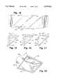
- FIG. 3is an exploded perspective view illustrating the frame cover and lens holder shown in FIG. 1;
- FIG. 4is a bottom perspective view of the lens holder depicted in FIG. 3;
- FIG. 5is a bottom view of the lens holder depicted in FIG. 3;
- FIG. 6is a bottom perspective view of the frame cover depicted in FIG. 3;
- FIG. 7is a front view of a lens depicted in FIG. 1;
- FIG. 8Ais a perspective view of one embodiment of an optical element in accordance with the present invention.
- FIG. 8Bis a perspective view of a support for the optical element shown in FIG. 8A;
- FIG. 9is a back view of the support depicted in FIG. 8B;
- FIG. 10is a cross sectional view of the support taken along lines C--C of FIG. 9;
- FIG. 11is a cross sectional view of a support taken along lines A--A of FIG. 9;
- FIG. 12is a cross sectional view of a support taken along lines B--B of FIG. 9;
- FIG. 13is a ray tracing of the optical system
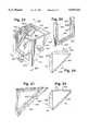
- FIG. 14is a perspective view of a modified optical element that is movable with respect to a support for varying the focal length of the optical system;
- FIG. 15is a perspective view of a modified support for the optical element illustrated in FIG. 14;
- FIG. 16is a front view of the modified support of FIG. 15;
- FIG. 17is a back cross sectional view of the support shown in FIGS. 15 and 16;
- FIG. 18is a front view of a lens modified so as to accommodate the support shown in FIGS. 15-17;
- FIG. 19is a cross section of a further embodiment of an optical element in accordance with the present invention.
- FIG. 20is a cross section of still another embodiment of an optical element in accordance with the present invention.
- FIG. 21is a cross section of a first embodiment of a hollow optical element in accordance with the present invention.
- FIG. 22is a back view of the optical element depicted in FIG. 21 with only a partial view of the reflector being illustrated;
- FIG. 23is a perspective view of a second embodiment of a hollow optical element in accordance with the present invention.
- FIG. 24is a cross sectional view illustrating the lenses and reflectors of one embodiment of the hollow optical element depicted in FIG. 23;
- FIG. 25is a cross sectional view of the lenses and reflector of a second embodiment of the hollow optical element depicted in FIG. 23;
- FIG. 26is a cross sectional view taken along lines of the mounting fixture depicted in FIG. 23 taken along lines A--A;
- FIG. 27is a cross sectional view of the mounting fixture depicted in FIG. 23 taken along lines B--B;
- FIG. 28is a perspective view of a nose bridge mounted in a nose bridge support
- FIG. 29is a side view of the nose bridge and nose bridge support depicted in FIG. 28;
- FIG. 30is a front view of the nose bridge depicted in FIG. 28;
- FIG. 31is a bottom view of a hinge depicted in FIG. 1;
- FIG. 32is a cross sectional view of the hinge taken along lines A--A of FIG. 31;
- FIG. 33is a cross sectional view of the hinge taken along lines B--B of FIG. 31;
- FIG. 34is a perspective top view of the temple and earpiece retainer depicted in FIG. 1;
- FIG. 35is a top view of the temple and earpiece retainer depicted in FIG. 34.
- FIG. 36is a side view of the temple and earpiece retainer depicted in FIG. 34.
- the head mounted display system 10 of the present invention as shown in FIG. 1includes a frame generally designated 12.
- the frame 12includes a lens or transparency 14, a lens holder 16, a top cover 18, right and left temples 20 and 21 and a nose piece 24.
- the frame 12supports a display 26 that may be formed of a miniature liquid crystal video display with or without a diffuser, diffractive grating, filter or lens.
- the displaymay be extremely small such as on the order of 0.6 inches by 0.9 inches but capable of generating a high resolution video image such as a T.V. image or computer generated image.
- the display 26is mounted over an aperture 84 in the lens holder 16 so that the information depicted on the display 26 can be reflected by a single optical element 28.
- the optical element 28has three distinct surfaces, an entrance surface S1 that receives video information from the display 26, an exit surface S3 wherein the user views the video image directly through the exit surface and a reflective surface S2 that reflects the video image from the entrance surface to the exit surface.
- the optical surfaces S1, S2 and S3 of the element 28are shaped to generate a magnified virtual image of the displayed information at an apparent location a distance from the user that is substantially greater than the actual distance between the display 26, the reflective surface S2, and the user's eye.
- the optical element 28may generate a virtual image the size of which along a diagonal is between 10 inches at an apparent distance from the user of 2 feet and 80 inches at an apparent distance of 15 feet.
- the optical elementis also shaped, as discussed in detail below, to minimize distortion, astigmatism and chromatic aberrations so as to provide a virtual image of high quality and resolution.
- the head mounted display system 10is modular in nature such that various components of the system 10 can be removed and replaced and/or adjusted so as to accommodate various users as well as various applications of the head mounted display system.
- the optical element 28is pivotally mounted in a support 30 so as to allow the optical path defined by the display 26, the optical element 28, and an eye of the user to be adjusted relative to a first axis which is the axis of rotation or axis about which the element 28 pivots.
- the support 30 and thus the optical element 28may also be moved in a generally horizontal direction towards and away from the nose piece 24 to accommodate users having different interpupillary distances.
- the optical element 28may also be adjustably mounted on the support 30 in a generally vertical direction so that a user can adjust the distance between the entrance surface of the optical element 28 and the display 26 to increase or decrease the apparent distance of the virtual image from the user.
- This spacing adjustmentallows a user who normally wears glasses or contact lenses to adjust the optical system to fit his personal accommodation power when the user is not wearing his glasses or contact lenses. Thus such a user can adjust the system so that he can see the image without his glasses or contact lenses.
- the nose piece 24is also movably mounted relative to the lens holder 16 so as to allow the distance between a bottom surface 32 of the lens holder 16 and the user's nose to be varied to adjust the optical path defined by the relative positions of the display 26, optical element 28, and the user's eye relative to a second, generally vertical axis.
- the nose piece 24is further completely removable from the frame 12 so that the head mounted display system 10 may be worn by a user wearing conventional glasses. More particularly, when worn by a person wearing glasses, the lens holder 16 rests on the frame of the glasses so that the nose piece of the glasses is in the same general position as the nose piece 24 would have been in if it had not been removed. Therefore, it is the nose piece of the conventional glasses that supports the frame 12 on the user when the nose piece 24 is removed.
- the support 30may be removed from the lens 14 so as to allow the optical system to be replaced. Further, because the support 30 is removably mounted on the lens 14, the lens 14 may be replaced without the need to replace the support 30 and optical element 28. More particularly, the lens 14 is removably mounted in a recess of the lens holder 16 so as to allow the lens 14 to be removed therefrom.
- This featureallows lenses or transparencies having various light transmissive or optical qualities to be mounted in the lens holder 16 and to be used with a single optical element 28 and support 30. For example, for indoor use, it is generally desirable to have a lens that is clear whereas for use outdoors, a tinted lens might be preferable.
- the use of a darker lenswill offer the user the perception of a brighter display; the ability to match the display illumination level with his external view or to use the display optic with his nondominant eye.
- the lens 14 and support 30are removable, the different lenses may be used with the same lens holder 16, support 30, and optical element 28 so as to make the head mounted display system 10 flexible and accommodate various applications.
- Each of the temples 20 and 21includes a respective hinge 34, 35 that exerts a force on the temples 20, 21 to direct the temples inward so that they hug the user's head.
- the hingesare removable so that hinges of various flexibility can be employed with the system 10 to allow the system to be worn more comfortably by users having large differences in head sizes.
- the system 10may include one or more earphones 38, 39. Each of the earphones 38, 39 is connected to a circuit contained within the cavity formed by the lens holder 16 and top cover 18 via wires 40, 41 and electrical connectors that fit into respective electrical jacks disposed on a bottom surface of the lens holder 16, as discussed below.
- the wires 40, 41are retained adjacent to the temples 20, 21 by hooks formed integrally with the hinges 34, 35.
- the wires 40, 41are removable from the hooks of the hinges 34, 35 and the earphone connectors are removable from the jacks in the lens holder 16 so as to enable the earphones 38, 39 to be removed from the display system 10 and replaced.
- the earphone retainers 36, 37are removably mounted on the respective temples 20, 21 so that they may also be removed from the system 10.
- the removable earphone retainers and earphonesallows a user to utilize different earphones that are connectable with the earphone jacks of the system 10.
- the top cover 18 and lens holder 16are shown in detail in FIGS. 3-6.
- the top cover 18has a top profile with a crescent-like shape and a generally flat top surface 40.
- a slight housing extension 46is formed in the top surface 44 to accommodate the display 26.
- An inner surface 48 of the top coveris formed with a rectangular recess 50 therein so as to receive an upwardly extending member 231 of the nose piece 24, as described in detail below, such that an outer surface of the nose piece member 231 received in the recess 50 is flush with the inner surface 48 of the top cover.
- a generally arcuate opening 52is formed in an end 54 of the top cover 18 to accommodate an electrical connector that mates to an electrical connector carried on an end of a single wire that couples video, audio, and power from a portable interface unit to the display 26 and circuitry contained in the housing formed by the top cover 18 and lens holder 16.
- the circuitry contained in the housing formed by the top cover 18 and lens holder 16 as well as the portable interface unitare disclosed in detail in U.S. patent application Ser. No. 07/793,155, filed Nov. 6, 1992, entitled PORTABLE VIDEO DISPLAY SYSTEM, and assigned to the Assignee of the present invention, and in U.S. patent application Ser. No. 07/986,422, filed Dec. 4, 1992 entitled HEAD MOUNTED VIDEO DISPLAY SYSTEM WITH PORTABLE VIDEO INTERFACE UNIT, and also assigned to the Assignee of the present invention.
- Each of these applicationsis incorporated herein by reference.
- a recess 56is also formed in an outer sidewall 58 of the top cover 18 so as to accommodate a brightness control knob or other control input for the display system. However, if desired, the brightness control input may be disposed on the portable interface unit.
- the top cover 18includes four symmetrically disposed hooks, only three of which, 60, 61, and 62, are shown to secure the top cover 18 to the lens holder 16.
- the hooks 60 and 61extend downwardly from an inner sidewall 64 of the top cover 18 such that an outer surface 66 of the hooks 60, 61 is flush with the surface 48 of the top cover.
- Each of the hooks 60, 61, and 62is formed with a protrusion 68 that extends in towards the cavity 70 of the top cover 18.
- the two hooks 62symmetrically disposed on an outer sidewall 72 of the top cover are such that the lower edge of the hooks 74 is flush with a lower edge 76 of the sidewall 72.
- the lens holder 16has a generally crescent-shape so that the outer walls of the lens holder 16 conform to the outer walls of the top cover 18.
- the lens holder 16supports on a top surface 80 thereof the display 26 and lower and upper printed circuit boards, not shown. More particularly, the top surface 80 is formed with a slight recess 82 therein that is generally square or rectangular in shape to mount the display 26.
- the recessis formed with a centrally located, generally rectangular aperture 84 over which is placed the face of the display 26 so that the displayed information can be received by the mirror 28.
- a number of short ribssuch as 86, 87, and 88 extend upwardly from the top surface 80 of the lens holder 16 so as to support a lower printed circuit board thereon.
- the lower printed circuit boardincludes at least one hole through which a boss 90 extends when the lower printed circuit board is mounted on the lens holder 16.
- the boss 90, a second boss 91, and a pair of large ribs 92 and 94are symmetrically disposed about the top surface 80 of the lens holder 16 so as to support the upper printed circuit board.
- the upper printed circuit boardincludes a pair of holes that are smaller in diameter than the diameter of the respective bosses 90, 91, but which are large enough to receive therein pins 95 and 96 extending upwardly from respective bosses 90, 91.
- the boardWhen the upper printed circuit board is mounted on the lens holder 16, the board rests on the ribs 92, 94, as well as on the upper surfaces of the respective bosses 90, 91 with the pins 95, 96 extending through the holes in the upper printed circuit board.
- the lens holder 16includes an indentation 100 that is formed in an innerwall 102 thereof, such that the indentation 100 is aligned with the recess 50 of the top cover 18 when the top cover 18 is mounted on the lens holder 16.
- the indentation 100forms an aperture through which a flange 246 on the nose piece 24 extends so as to mount the nose piece 24 on the frame 12.
- a pair of upwardly extending ribs 104 and 106, having an arcuate upper surface,are disposed in an end 108 of the lens holder 16 so as to be aligned with the arcuate opening 52 formed in the top cover 18 when the top cover 18 is mounted on the lens holder 16.
- the ribs 104 and 106support the electrical connector that mates with the connector coupled to the end of the single wire providing the video, audio, and power from the portable interface unit to the display 26 and lower and upper printed circuit boards.
- the lens holder 16has a generally flat bottom surface 110 with a longitudinally extending recess 112 formed therein.
- the recess 112extends substantially the length of the front of the lens holder so as to be able to receive therein the upper edge of the frame of a pair of conventional glasses when the nose piece 24 is removed from the display system 10. More particularly, when the display system 10 is worn by a user also wearing a pair of glasses, the surface 116 of the recess 112 rests on the upper edge of the frame of the glasses so that the display system 10 is supported by the glasses frame, and in particular, by the nose piece of the glasses.
- the recess 112is positioned in the bottom surface 110 of the lens holder 16 so that when supported on a pair of glasses, the nose piece of the glasses is in substantially the same position that the nose piece 24 would be if not removed from the frame 12. It is noted that although the recess 112 is shown extending to the outer sidewall 114 of the lens holder 16, it need not extend so far, but only enough to receive the upper edge of a frame of a pair of glasses wherein at least a portion of the recess 112 is between an innerwall 118 and/or the inner sidewall 102 of the lens holder 16 and the aperture 84 for the display 26.
- a hollow box-shaped member 120is formed in a central location on the bottom surface 110 of the lens holder 16, and in particular, in the recess 112 adjacent to the outer sidewall 114 of the holder 16 so as to receive a member 244 of the nose piece 24, as described in detail below. More particularly, the box member 120 includes an aperture 122 formed between a pair of sidewalls 124 and 125 where the aperture 122 is aligned with the indentation 100.
- one flange 244 of the nose piece 24extends through the aperture 122 into the box member 120, whereas a second flange 246 extends through the aperture formed by the indentation 100 into the cavity or housing formed by the top cover 18 and lens holder 16, so as to removably mount the nose piece 24 on the frame 12.
- a pair of earphone jack mounting members 130 and 131are integrally formed on the bottom surface 110 of the lens cover 116 adjacent respective ends 108 and 132 of the lens holder 16.
- the earphone jack mounting members 130, 132extend downwardly from the bottom surface 110 of the lens holder 16, and each member 130, 131 includes a respective aperture 134, 136 so as to allow an earphone connector to be inserted therethrough for connection with the jack mounted in the members 130, 131.
- the ends 108 and 132 of the lens holder 16are also formed with respective T-shaped apertures therein, 138 and 140, so as to receive and movably mount the respective T-shaped ends of the respective hinges 34 and 35, as discussed in detail below.
- the outer sidewall 114 of the lens holder 16is formed with a longitudinally extending recess 142 that extends substantially the length of the outer sidewall 114 between an inner surface 144 of the outer wall 114 and an innerwall 146, wherein the recess 142 receives the lens or transparency 14 of the frame 12.
- Five ribsare symmetrically disposed in the recess 142 formed between the outer wall 114 and innerwall 146 so as to engage hooks formed on the lens 14 in order to maintain the lens 14 in place on the frame 12.
- the lens 14 as shown in FIG. 7includes, adjacent an upper edge 160 thereof, five L-shaped indentations 161-165 so as to form five hook members 166-170 in the lens
- the hook members 166-170are symmetrically disposed along the upper edge 160 of the lens 14 and are spaced in accordance with the spacing of the ribs 150, 151, 152, 156, and 158, so as to engage an upper surface of the ribs to mount the lens 14 on the lens holder 16.
- the hook members 166-170 of the lens 14all extend in the same direction so that the lens may be mounted on the lens holder 16 by sliding the lens 14 in the recess 142 to the left, or by reversing the lens 14 and sliding the lens in the recess 142 to the right.
- the lens 14may be mounted with a mirror mounting surface generally designated 180 on the right side or the left side of the display system.
- the lens mounting surface 180includes a pair of upwardly extending slots 182 and 184 that receive therein respective sidewalls of the mirror support 30.
- the mirror mounting surface 180 of the lens 14includes a slot 186 that extends horizontally between the upwardly extending slots 182 and 184. The horizontally extending slot 186 receives a protrusion formed on the mirror support 30, as described in detail below, so as to maintain the mirror support 30 securely on the lens 14.
- the lens 14may be formed of a lightweight plastic, or the like, that is flexible or bendable so that the lens, when mounted in the recess 142, conforms to the arcuate shape of the recess, as shown in FIG. 1. Further, the lens 14 may be formed with different diopters so as to accommodate people that are slightly near-sighted or far-sighted for example. Although the lens 14 is shown in FIG. 7 as a single lens, the lens 14 may be split into two lenses, one covering the right side of the display system, and the other covering the left side of the display system, if desired. The lens 14 may also be tinted for outdoor use, for example, or the lens 14 may be clear for indoor use. Because the lens is removably mounted on the lens holder 16, the lens 14 can easily be changed to suit a particular application of the display system 10.
- the optical element 28 in accordance with one embodiment of the present inventionincludes an entrance surface S1 for receiving the video image directly from the display 26.
- a reflective surface S2reflects the video image from the entrance surface S1 to the exit surface S3 of the optical element 28.
- the reflective surface S2may reflect by total internal reflection or by applying a reflective coating to the surface.
- the exit surface S3faces the user's eye when the optical element 28 is positioned correctly on the head mounted display system 10 to allow the user to view the video image directly through the exit surface S3.
- the reflective surface S2is curved so as to contribute to the total magnifying power of the optical element 28.
- the reflective surface S2may be, for example, a concave spherical surface with a radius of curvature approximately 252 mm.
- the entrance surface S1is made cylindrical so as to introduce an astigmatism that cancels the astigmatism introduced by the reflective surface S2.
- the cylindrical entrance surface S1is convex and has a radius of curvature of approximately 62 mm. As shown in FIG. 13, the axis of a hypothetical cylinder having the surface S1 would extend generally parallel to the line 310 with the radius of curvature extending from that axis to the surface S1.
- the exit surface S3 of the optical elementis formed so as to principally control the field of view, i.e., the size of the virtual image that is projected by the optical element 28 at a given focal length.
- the exit surface S3also controls the location of the virtual image with respect to the user.
- the exit surface S3is convex spherical with a radius of curvature of 54.6 mm.
- FIG. 13Aillustrates a ray tracing of the optical element 28 generated by a software package "Beam 4 Optical Ray Tracer” by Stellar Software and using techniques described in the text "Elements of Modern Optical Design", 1985, Donald C. O'Shea, published by John Wiley and Sons, Inc.
- This ray tracingis helpful to more completely describe the configuration of each of the surfaces S1, S2, and S3.
- the entrance surface S1is a cylindrical surface having a radius of curvature of 62 mm.
- the entrance surface S1has a pitch of -7° so that the line 310 in FIG. 13 that extends through the vertex 312, is 7° in the clockwise direction from a line that is parallel to the X axis and that also extends through the vertex 312. If one looks at the entrance surface S1 from the position of the display 26, the surface S1 is approximately 13 mm high and 25.4 mm wide.
- the reflective surface S2is a spherical surface having a radius of curvature of 252 mm.
- the reflective surface S2has a pitch of 37.9523° so that the line 316 of the surface S2 extending through the vertex 314 is 37.9523° in a counterclockwise direction from a line parallel to the X axis and that also extends through the vertex 314. If one looks at the back of the reflective surface S2 towards the direction of the display 26, the reflective surface S2 is 25.4 mm wide and 16.8 mm high.
- the spherical exit surface S3has a radius of curvature of 54.6 mm, as described above.
- the exit surface S3has a pitch of 83.5° so that the line 320 of S3 extending through the vertex 318 is approximately 83.5° in the counterclockwise direction from a line that is parallel to the X axis and that also extends through the vertex 318. If one looks towards the surface S1, as if the optical element 28 were installed in the head mounted display system 10, the surface S3 is approximately 25.4 mm wide and 13.4 mm high.
- FIG. 13the display 26 is tipped 7° in the counterclockwise direction with respect to the depicted X axis.
- a 75° angle of viewis provided by the optical system shown in FIG. 13. The angle of view represents the angle between a line extending from zero on the X axis to the vertex 314 of surface S2 and a second line extending from the vertex 314 to the vertex of the cornea.
- the optical element 28 shown in FIG. 8A for the head up display system 10essentially eliminates distortion, astigmatism and chromatic aberrations perceived by a user in viewing a video image such as a movie. More particularly the normalized longitudinal axial chromatic aberration, L CH , of the image on the retina of an emmetropic eye generated by the element 28 is less than 58 microns and preferably less than 29 microns. L CH may be thought of as the depth of the chromatic aberration.
- the transverse axial chromatic aberration, T cof the image on the retina of an emmetropic eye generated by the element 28 is less than 28 microns and is preferably less than 14 microns. T c may be thought of as the height of the chromatic aberration.
- the distortion of the image on the retina of an emmetropic eye generated by the optical element in the Z - X planeis -0.053 and in the Z - Y plane is +0.04 where the X, Y and Z planes are not as shown in the ray tracing of FIG. 13 but are defined in accordance with typical optical convention such that the Z axis is generally parallel to the axis labeled X in FIG. 13 and the Y axis is generally parallel to the axis labeled Z in FIG. 13.
- the distortion in the Z - X planemay be made approximately equal to the distortion in the Z - Y plane and less than 1% by configuring the surface S1 as a toric as opposed to a cylindrical surface. Further, by configuring the surface S1 as a toroidal surface, the field of curvature of the image in the X - Y plane may be made approximately equal to the field of curvature in the Z - X plane and each radius approaching infinity.
- the optical element 28 shown in FIG. 8A and thus described,will generate a virtual image that appears to be approximately 48 inches wide and 32 inches high at a location that is approximately 10 feet from the user. It is noted that the size of the virtual image at a given distance from the user may be increased by adding more magnifying power to one or more of the three surfaces S1, S2, and S3 of the optical element; however, chromatic aberrations may result with increases in the magnifying power of the surfaces.
- the optical element 28is formed of a solid block of material such as an acrylic, PMMA (poly-methylmethacrylate) which has a low chromatic dispersion.
- the optical element 28may be machined to provide the desired curvatures of surfaces S1, S2 and S3.
- the optical element 28may be formed by injection molding.
- a knob 208extends from each side 210 of the optical element 28 so as to allow the element 28 to be mounted in the support 30, described below.
- the support 30 for the optical element 28 of FIG. 8Ais shown in detail in FIGS. 8B-10.
- the support in this embodimentincludes a frontwall 190 that extends across the support 30 between a pair of sidewalls 192, 194.
- a backwall 196also extends between the sidewalls 192, 194.
- the backwall 196is spaced from the frontwall to form a recess 198 therebetween so that the mirror support mounting portion 180 of the lens 14 can be received in the recess 198.
- the frontwall 190includes a longitudinally extending protrusion or hook that extends from the back surface of the frontwall towards the backwall 196.
- the support 30also includes a pair of arms 202 and 204 that extend from opposite sides of the backwall 196 in a direction away from the frontwall 190.
- Each of the arms 202, 204includes an aperture 206 for receiving therein respective knobs 208 on opposite sides 210 of the optical element, so as to removably mount the optical element 28 in the support 30. It is noted that this mounting of the optical element 28 in the support 30 allows the optical element 28 to be rotated about an axis that extends generally through the center of the knobs 208, so that a user can adjust the optical path defined by the display 26, the optical element 28, and the user's eye.
- the support 30is shaped with a varying cross section such that the arm 202 extends inwardly towards the user's face from the backwall 196, a greater distance than the arm 204. Therefore, when the optical element 28 is mounted in the aperture 206 of the respective arms 202 and 204, the optical element 28 is in a position such as shown by the dotted line 206 of FIG. 10, wherein the axis of the element 28 extending between the centers of the knobs 208 is not parallel to the backwall 196 of the support 30, but is at an angle thereto. However, this mounting does allow the axis 212 of the optical element 28 to be generally parallel to the user's face for easy viewing. Because the support 30 can be removed from the lens 14, the lens 14 may be changed so as to accommodate the various environments in which the display system 10 is used without the need for replacing the optical element 28 and support 30 also.
- the optical element 28includes, on each of its sides 340, a plurality of tiny apertures or detents 342 that are aligned in a row that extends generally parallel to the edge of the exit surface S3 abutting the sidewall 340.
- Each aperture on one sidewall 340 of the optical element 28has an associated aperture on the opposite sidewall of the optical element 28 to form a pair of apertures that are in the same horizontal plane such as the aperture pair 341.
- the support 30 for the optical element shown in FIG. 14is also modified as shown in FIGS. 15-17.
- the modified support 30does not include the apertures 206 in the arms 202 and 204, but includes solid arms 346 and 348.
- Each of the arms 346 and 348includes a small cone-shaped protrusion 350, 352 that extends inwardly from the respective arm 346, 348 towards the optical element 28.
- the modified optical element 28 of FIG. 14is mounted on the modified support 30 of FIGS. 15-17 by inserting the protrusions 350, 352 into a pair of horizontally-aligned apertures 342.
- the modified optical element 28may have a plastic finger tab 344 mounted thereon such that the tab 344 extends downwardly from the optical element 28.
- the usercan adjust the distance between the entrance surface S1 and the display 26 by pulling down on the finger tab 344 or by pushing up thereon so as to cause the protrusions 350, 352 to engage different pairs of horizontally-aligned apertures 342.
- the apertures 342 in the modified optical element 28allow the distance between the entrance surface S1 and the display 26 to be adjusted over a range of 5 mm.
- This focal length adjustmentallows the location of the virtual image to be varied with the apparent distance of the virtual image from the user ranging from 2 feet to 40 feet. It is noted that although the focal length, i.e.
- the distance from S3 to the apparent location of the imageremains approximately 50 mm, as the optical element is moved vertically closer to the display, the user's eye adjusts to perceive the image as moving closer.
- the exit ray anglei.e. the angle of the rays leaving S3 changes so that the focal length of the whole system including the display, the optical element 28 and the lens of the user's eye changes.
- the modified optical element 28is moved towards and away from the display 26 so as to vary the apparent distance of the virtual image from the user, the size of the virtual image increases/decreases as the apparent distance of the virtual image from the user is increased/decreased.
- the apertures 342may be formed on the optical element 28 as shown or on a portion of the finger tab 344. In the latter instance the upper sidewalls 345 of the tab 344 would be enlarged to extend past the position of the apertures shown in FIG. 14. This modification would enable apertures formed on the finger tab sidewalls 345 to be located at the same distance from the exit surface S3, as shown in FIG. 14. Further, instead of individual apertures 342, a longitudinal groove may be formed in the optical element or finger tab sidewall at the same distance from the exit surface, as shown for the apertures 342. This longitudinal groove would allow infinite vertical adjustments within a given range to be made. In this embodiment the protrusions 350, 352 of the modified support 30 of FIG. 16 would preferably be wedge-shaped.
- the wedge-shaped protrusions and arms 348 and 350 of the support 30would exert a spring force on the optical element to maintain the element 28 in position on the support 30, but they would allow the optical element to be moved closer or further away from the display 26 to vary the apparent location of the virtual image from the user, as discussed above.
- the modified support 30 shown in FIGS. 15-17may be mounted on a modified lens 14, as shown in FIG. 18, so as to allow the user to move the modified support 30 and optical element 28 horizontally towards and away from the nose piece 24.
- This horizontal movementallows the head mounted display system 10 to accommodate users having very different interpupillary distances.
- the modified lens 14includes a horizontally-extending slot or indentation 360.
- a longitudinal, i.e., horizontally-extending, protrusion 361extends from the back surface 365 of the front wall 363 of the modified support 30. This protrusion extends into the slot or indentation 360 of the modified lens to allow the support 30 of FIGS. 16-17 to be guided along the slot 360 towards and away from the nose piece 24.
- the lens bottom 367moves through respective slots 369 in the arms 346 and 348 of the modified support 30.
- the optical element 28floods the eye with the ray bundle representing the virtual image such that the diameter of the ray bundle is greater than the diameter of the user's pupil, fine horizontal adjustments to the optical element 28 to account for variations in the interpupillary distance between various users need not be made.
- the adjustment for variations in the interpupillary distance provided by the slot 360 in the modified lens 40provides a gross adjustment to enable the head mounted display system 10 to accommodate people with large variations in their interpupillary distance.
- the optical elements 28 shown in FIG. 8A and FIG. 14are made of a single material, such as PMMA.
- the optical element 28can be modified, however, to be made of two or more different materials so as to provide an achromatic optical element. More particularly, as shown in FIG. 19, the exit surface S3 is formed on a thin positive lens 370 of a material having a low index of refraction, for example 1.49, and an ABBE value of 61.93, such as for PMMA.
- the remaining bulk 372 of the optical elementmay be formed of a material having a higher index of refraction, for example 1.585, and an ABBE value of 31.0 such as for polystyrene.
- the optical element 28can be formed into a chromatic doublet contributing minimal chromatic aberrations.
- the entrance and exit surfaces S1 and S3may both be formed on a respective thin, positive lens 380, 381 made of PMMA.
- the lenses 380 and 381may then be bonded to a negative lens 382 of polystyrene to form the optical element 28 with minimal chromatic aberrations.
- the lenses 380, 381 and 382may be made of three different materials to form a Cooke triplet.
- FIGS. 21 and 22illustrate another embodiment of the optical element 28 in accordance with the present invention.
- the optical element 28is hollow, the element having an air-filled cavity 400.
- the optical element 28 shown in FIGS. 21-22is formed in two parts 402 and 414.
- a first part generally designated 402includes a thin lens portion 404 on which the entrance surface S1 of the optical element 28 is formed.
- the part 402also includes a second lens portion 406 on which the exit surface S3 is formed.
- the part 402 of the optical elementalso includes a pair of sidewalls 408 and 410 that are integrally formed with the lens portions 404 and 406. As shown in FIG.
- a ledge 412is formed at the back of the part 402 so as to provide a mounting surface for a mirror 414 that forms the reflective surface S2. Because the walls of the lens portions 404 and 406 are very thin, the part 402 may be easily formed by injection molding techniques.
- the optical element 28 shown in FIG. 21can be such that the entrance lens portion 404 and the exit lens portions 406 are made of two different materials to form an achromat. Further, either or both of the individual lens portions 404 and 406 can be formed of two different materials such that the individual lens portion 404, 406 is an achromat.
- the surfaces S1, S2, and S3 of the optical elements shown in FIGS. 19-23may be formed such that the entrance surface S1 is a cylindrical or toroidal surface and the reflective surface S2 and exit surface S3 are spherical surfaces, as described above.
- the reflective surface S2may be made flat and the refractive surfaces S1 and S3 may be made spherical with increased magnification powers to account for the loss of magnification resulting from the surface S2 being made flat.
- the entrance surface S1may be made flat, as well as the reflective surface S2, wherein the exit surface S3 is the only curved surface of the optical element.
- FIGS. 23-27illustrate a further embodiment of the hollow optical element 28 in accordance with the present invention.
- This hollow optical element 28includes an entrance lens 452 or 456 on which the entrance surface S1 is formed.
- the optical element 28 shown in FIG. 23also includes an exit lens 454 or 458 on which the exit surface S3 is formed.
- the entrance lens 452, 456; exit lens 454, 458; and a reflector 453are fixedly supported in a mounting fixture 460 so as to form a single integral optical element 28.
- the mounting fixture 460includes a front portion 461 having a pair of sidewalls 464 and 465 with a bottom wall 468 extending between the sidewalls. It is noted that although the sidewalls 464 and 465 are generally triangular and extend across the entire sides of the optical element 28, the bottom wall 468 is relatively small so that it merely forms a base for a slot 463 in which the exit lens 454, 458 is positioned and a base for a slot 486 into which the bottom portion 470 of the reflector 453 is positioned. More particularly, the slot 463 for the exit lens is formed between a pair of U-shaped outer and inner ribs 460 and 462.
- the top surface 466 of the U-shaped inner rib 462does not extend to the height of the outer rib 460 so that a ledge portion 466 is formed on the inner rib 462.
- the ledge 466supports the periphery of the entrance lens 452, 456 when mounted on the fixture 460.
- the portion 480 of the fixture 460 in which the mirror 453 is mountedis U-shaped (in a manner similarly to the front portion 461 of the fixture 460) with inner and outer ribs 482 and 484 formed therein.
- the portion 480 of the fixture 460is at a predetermined angle with respect to the front portion 461 of the optical element 28 so as to fix the angle between the reflective surface S2 and the exit surface S3.
- the ribs 482 and 484 of the reflector mounting portion 480are spaced so as to provide a slot 486 therebetween wherein the ribs 482 and 484 engage three peripheral sides of the reflector 453.
- the entrance lensis positioned on the ledge 466 wherein a ledge 466 may extend from the front of the optical element to the back thereof on each of the sidewalls 464 and 465. Alternatively only partial ledge supports need be provided.
- the reflector 453is preferably a flat reflector; whereas both the entrance lens 452 and the exit lens 454 are curved so as to form spherical lenses or the like that each contribute to the magnification power of the optical element 28.
- the entrance lens 456may be formed of a flat piece of glass and the exit lens may be curved so as to include all of the magnification power of the optical element 28.
- each of the sidewalls 464may be provided with a knob 465 for mounting in the support 30 of FIG. 8B.
- the sidewalls 464may be provided with apertures 342 so that the element of FIG. 23 may be mounted in the modified support 30 shown in FIGS. 15-17.
- the nose piece 24includes a nose bridge 220 that is made of a relatively soft, flexible material for supporting the display system 10 on the user's nose when the user is not wearing a conventional pair of glasses.
- the nose piece 24also includes a flange 224 that extends upwardly from a base 226 of the nose bridge 220 where the flange 224 is preferably formed of a relatively rigid plastic.
- the flange 224 on a front surface thereofincludes a number of protrusions 227-229 to allow the nose piece 24 to be adjustably mounted in a nose piece holder 230.
- the nose piece holder 230includes an upwardly extending, generally rectangularly-shaped and hollow member 231 for receiving the flange 224.
- the nose bridge holder member 231includes apertures 232, 233, and 234 that are vertically aligned so as to receive respective vertically aligned protrusions 227, 228, and 229 on the flange 224 when the nose piece 24 is in a fully retracted position.
- the flange 224is moved downward in the member 231 of the nose bridge holder so that the protrusions 227 and 228 extend through the apertures 233 and 234.
- the flange 224is moved downwardly so that the protrusion 227 is received in the aperture 234.
- the nose bridge 220is at its greatest distance from the lens holder 16.
- This adjustable mounting for the nose bridge 220allows the distance between the lens holder 16 that supports the display 26 and the user's nose to be varied to adjust the optical path defined by the relative position of the display 26, the optical element 28, and the user's eye to be adjusted relative to a generally vertical axis defined by the apertures 232-234.
- This featurethus allows the display system 10 to more easily accommodate users having different head sizes and head configurations so that the display system 10 may be easily worn and the image of the displayed information be easily viewed via the optical element 28.
- the nose bridge 220may, or may not, be completely removable from the nose bridge holder 230.
- the nose bridge holder 230includes a base member 240 that extends at generally right angles from the upwardly extending member 231, the base member 240 having an aperture 242 therein so as to allow the flange 224 of the nose bridge to be received therein and extend upwardly into the member 231.
- the base 240further includes a flange 244 extending outwardly therefrom.
- the upstanding member 231 of the nose bridge holder 230also includes a flange 246 that extends at generally right angles from the upstanding member 231 and generally parallel to the flange 244 of the base 240.
- the flange 244 on the base 240 of the nose bridge holder 230is inserted into the aperture 122 formed on the bottom surface 116 of the lens holder.
- the flange 246 extending from the upstanding member 231 of the nose bridge holder 230is inserted into the aperture formed by the indentation 100 of the lens holder and the rectangular recess 50 of the top cover 18 so that the flange 246 extends into the housing formed by the lens holder 16 and the top cover 18.
- the base member 240is formed with a lip or hook portion 250 to engage a wall defining the aperture 122 of the box 120.
- the nose piece 24may be removably mounted on the frame 12 of the display system 10. The nose piece 24 is easily removed to allow the display system 16 to be worn with a pair of conventional glasses, as described in detail above.
- FIG. 31An example of a hinge suitable for the hinges 34, 35 of the temples 20, 21, is depicted in FIG. 31.
- the hinge 34, 35has an elongated body that is curved inwardly towards the user's head when the hinge is mounted on the lens holder 16.
- the body 250includes a generally T-shaped mounting member 252 that is receivable in a T-shaped aperture 138, 140 so as to removably mount the hinge on the lens holder 16.
- the body 250 of the hinge 34, 35 at an opposite end of the member 252has an additional generally T-shaped mounting member 254 that is received in an aperture 272 of the temple 20, 21 so as to secure the hinge 34, 35 to the remainder of the temple bar.
- the hinge body 250also includes a number of outwardly extending ribs 256-261.
- Alternate ribs 256, 258 and 260include a pair of generally parallel extending rib fingers 262 and 264, extending from the respective rib body so as to form an aperture 266 between the fingers 262 and 264 in order to maintain the wire 40, 41 of the earphone 38, 39 therein.
- Alternate ribs 257, 259, and 261have only a single rib finger 268 extending therefrom so as to guide the wire 40, 41, but not retain it.
- the rib fingers 262 and 264 of each of the ribs 256, 258, and 260are flexible so that the wire 40, 41 of the earphone may be easily inserted therein and removed therefrom.
- the temple bar 270 of the temples 20, 21is shown in FIGS. 34-36.
- the temple bar 270includes an aperture 272 formed in an end 274 thereof so as to receive the generally T-shaped end 254 of the hinge 34, 35 to mount the temple 270 on the hinge 34, 35.
- the temple bar 270includes a longitudinally extending groove 276 that is formed in an upper surface of the temple bar so as to guide a mounting member 278 of a ring earphone retainer 36, 37.
- the temple bar 270also includes a second groove, not shown, that extends longitudinally along a bottom surface 280 of the temple so as to receive portions 282 and 283 of the ring retainer 36, 37 therein.
- the grooves 276guide the ring retainer 36, 37 along the length of the temple bar 270 so that the position of the ring retainer 36, 37 along the temple bar 270 may be adjusted. Further, the mounting members 278, 282, and 283 of the ring earphone retainers 36, 37 allow the retainer to be removably mounted on the temple bar 270. If a user of the display system 10 desires to use speakers or earphones different than the earphones 38, 39, the earphones 38, 39 can be removed, as described above. Similarly, the earphone ring retainers 36, 37 may be snapped off the temple bar 270 to remove them from the display system 10. Other earphones or booms that may be used with the display system 10 preferably have a mounting member that is receivable in the grooves 276 of the temple bar 270 to allow the earphone, speaker or boom to be mounted on the frame 12 of the system 10.
- an optical element 28, in accordance with the present inventionmay also be used in a binocular or stereoscopic head-up display system. Further, the distance of the virtual image from the user could be varied by moving the display instead of the optical element 28.
- Many other modifications and variations of the present inventionare possible in view of the above teachings, as will be apparent to one of ordinary skill in the art. Therefore it is to be understood that, within the scope of the appended claims, the invention may be practiced otherwise than as described hereinabove.
Landscapes
- Physics & Mathematics (AREA)
- General Physics & Mathematics (AREA)
- Optics & Photonics (AREA)
- Instrument Panels (AREA)
- Devices For Indicating Variable Information By Combining Individual Elements (AREA)
- Apparatus For Radiation Diagnosis (AREA)
- Control Of Indicators Other Than Cathode Ray Tubes (AREA)
- Road Signs Or Road Markings (AREA)
- Fittings On The Vehicle Exterior For Carrying Loads, And Devices For Holding Or Mounting Articles (AREA)
Abstract
Description
Claims (66)
Priority Applications (11)
| Application Number | Priority Date | Filing Date | Title |
|---|---|---|---|
| US08/045,919US5539422A (en) | 1993-04-12 | 1993-04-12 | Head mounted display system |
| JP52321894AJP3917174B2 (en) | 1993-04-12 | 1994-03-29 | Head mounted display system |
| EP94913320AEP0694196B1 (en) | 1993-04-12 | 1994-03-29 | A head mounted display system |
| AU65531/94AAU6553194A (en) | 1993-04-12 | 1994-03-29 | A head mounted display system |
| DE69427398TDE69427398T2 (en) | 1993-04-12 | 1994-03-29 | DISPLAY SYSTEM ON THE HEAD |
| DK94913320TDK0694196T3 (en) | 1993-04-12 | 1994-03-29 | Upside down display system |
| PCT/US1994/003410WO1994024658A1 (en) | 1993-04-12 | 1994-03-29 | A head mounted display system |
| CA002160244ACA2160244A1 (en) | 1993-04-12 | 1994-03-29 | A head mounted display system |
| AT94913320TATE201934T1 (en) | 1993-04-12 | 1994-03-29 | HEADWEAR DISPLAY SYSTEM |
| ES94913320TES2159301T3 (en) | 1993-04-12 | 1994-03-29 | A VISUALIZER SYSTEM FOR MOUNTING ON THE HEAD. |
| JP2006304540AJP2007094422A (en) | 1993-04-12 | 2006-11-09 | Head mounted display system |
Applications Claiming Priority (1)
| Application Number | Priority Date | Filing Date | Title |
|---|---|---|---|
| US08/045,919US5539422A (en) | 1993-04-12 | 1993-04-12 | Head mounted display system |
Publications (1)
| Publication Number | Publication Date |
|---|---|
| US5539422Atrue US5539422A (en) | 1996-07-23 |
Family
ID=21940546
Family Applications (1)
| Application Number | Title | Priority Date | Filing Date |
|---|---|---|---|
| US08/045,919Expired - Fee RelatedUS5539422A (en) | 1993-04-12 | 1993-04-12 | Head mounted display system |
Country Status (10)
| Country | Link |
|---|---|
| US (1) | US5539422A (en) |
| EP (1) | EP0694196B1 (en) |
| JP (2) | JP3917174B2 (en) |
| AT (1) | ATE201934T1 (en) |
| AU (1) | AU6553194A (en) |
| CA (1) | CA2160244A1 (en) |
| DE (1) | DE69427398T2 (en) |
| DK (1) | DK0694196T3 (en) |
| ES (1) | ES2159301T3 (en) |
| WO (1) | WO1994024658A1 (en) |
Cited By (186)
| Publication number | Priority date | Publication date | Assignee | Title |
|---|---|---|---|---|
| US5742373A (en)* | 1995-10-13 | 1998-04-21 | Massachusetts Institute Of Technology | Color microdisplays and methods of manufacturing same |
| US5768024A (en)* | 1994-11-25 | 1998-06-16 | Olympus Optical Co., Ltd. | Image display apparatus |
| US5771124A (en)* | 1996-07-02 | 1998-06-23 | Siliscape | Compact display system with two stage magnification and immersed beam splitter |
| US5838498A (en)* | 1994-12-21 | 1998-11-17 | Siliscape, Inc. | Miniature synthesized virtual image electronic display |
| US5867134A (en)* | 1995-08-25 | 1999-02-02 | Alvelda; Phillip | VLSI visual display |
| US5870068A (en)* | 1994-12-21 | 1999-02-09 | Siliscape, Inc. | Twice folded compound magnified virtual image electronic display |
| WO1999020172A1 (en) | 1997-10-16 | 1999-04-29 | Odyssey Optical Systems, Llc | Portable fundus viewing system for an undilated eye |
| US5912769A (en)* | 1995-07-03 | 1999-06-15 | Canon Kabushiki Kaisha | Optical element, combination optical element, and observation system using such optical elements |
| US5949388A (en)* | 1995-03-03 | 1999-09-07 | Olympus Optical Co., Ltd. | Head-mounted video display |
| US5982553A (en) | 1997-03-20 | 1999-11-09 | Silicon Light Machines | Display device incorporating one-dimensional grating light-valve array |
| US6088102A (en) | 1997-10-31 | 2000-07-11 | Silicon Light Machines | Display apparatus including grating light-valve array and interferometric optical system |
| US6097542A (en)* | 1996-10-16 | 2000-08-01 | Olympus Optical Co., Ltd. | Optical system having reflecting surface of non-rotationally symmetric surface configuration |
| US6097354A (en)* | 1997-05-27 | 2000-08-01 | Olympus Optical Co., Ltd. | Image display apparatus |
| US6101036A (en) | 1998-06-23 | 2000-08-08 | Silicon Light Machines | Embossed diffraction grating alone and in combination with changeable image display |
| US6130770A (en) | 1998-06-23 | 2000-10-10 | Silicon Light Machines | Electron gun activated grating light valve |
| US6151167A (en)* | 1998-08-05 | 2000-11-21 | Microvision, Inc. | Scanned display with dual signal fiber transmission |
| US6215579B1 (en) | 1998-06-24 | 2001-04-10 | Silicon Light Machines | Method and apparatus for modulating an incident light beam for forming a two-dimensional image |
| US6271808B1 (en) | 1998-06-05 | 2001-08-07 | Silicon Light Machines | Stereo head mounted display using a single display device |
| US6310728B1 (en) | 1998-06-19 | 2001-10-30 | Canon Kabushiki Kaisha | Image viewing apparatus |
| WO2001027684A3 (en)* | 1999-10-09 | 2001-11-22 | Optimize Inc | Eyeglass-mount display having personalized fit module |
| US6330121B1 (en)* | 1997-11-17 | 2001-12-11 | Olympus Optical Co., Ltd. | Optical prism, display element support and optical assembly using the same |
| US20020019296A1 (en)* | 1998-06-24 | 2002-02-14 | Viztec, Inc., A Delaware Corporation | Wearable device |
| US6351252B1 (en)* | 1998-04-10 | 2002-02-26 | Olympus Optical Co., Ltd. | Head-mounted picture display device |
| US6394601B1 (en)* | 2000-07-17 | 2002-05-28 | David S. Bettinger | Spectacle-mounted micro display ocular |
| US6396461B1 (en) | 1998-08-05 | 2002-05-28 | Microvision, Inc. | Personal display with vision tracking |
| US6404557B2 (en) | 1999-09-10 | 2002-06-11 | Inviso, Inc. | Display illumination system |
| US20020080496A1 (en)* | 2000-12-23 | 2002-06-27 | Michael Kaschke | Stereoscopic display system having a single display |
| US6474808B1 (en)* | 1999-11-29 | 2002-11-05 | David S. Bettinger | Spectacle-mounted ocular display apparatus |
| US6490095B2 (en) | 2000-03-23 | 2002-12-03 | Canon Kabushiki Kaisha | Image display apparatus |
| US20030030597A1 (en)* | 2001-08-13 | 2003-02-13 | Geist Richard Edwin | Virtual display apparatus for mobile activities |
| US6552854B2 (en) | 2000-04-28 | 2003-04-22 | Canon Kabushiki Kaisha | Image display apparatus and optical system |
| US20030107816A1 (en)* | 2001-11-14 | 2003-06-12 | Akinari Takagi | Display optical system, image display apparatus, image taking optical system, and image taking apparatus |
| US6583772B1 (en) | 1998-08-05 | 2003-06-24 | Microvision, Inc. | Linked scanner imaging system and method |
| US6594085B2 (en) | 2000-04-28 | 2003-07-15 | Canon Kabushiki Kaisha | Image display apparatus and optical system |
| US20030184868A1 (en)* | 2001-05-07 | 2003-10-02 | Geist Richard Edwin | Head-mounted virtual display apparatus with a near-eye light deflecting element in the peripheral field of view |
| US20030197943A1 (en)* | 2001-11-14 | 2003-10-23 | Shoichi Yamazaki | Optical system, image display apparatus, and image taking apparatus |
| US20030204578A1 (en)* | 2002-04-26 | 2003-10-30 | Michael Yip | Method and apparatus for restoring the configuration of a network device |
| US20030236838A1 (en)* | 2002-04-09 | 2003-12-25 | Ouchi Norman Ken | Shared and private node workflow system |
| US6707591B2 (en) | 2001-04-10 | 2004-03-16 | Silicon Light Machines | Angled illumination for a single order light modulator based projection system |
| US6712480B1 (en) | 2002-09-27 | 2004-03-30 | Silicon Light Machines | Controlled curvature of stressed micro-structures |
| US6714337B1 (en) | 2002-06-28 | 2004-03-30 | Silicon Light Machines | Method and device for modulating a light beam and having an improved gamma response |
| US6728023B1 (en) | 2002-05-28 | 2004-04-27 | Silicon Light Machines | Optical device arrays with optimized image resolution |
| US6747781B2 (en) | 2001-06-25 | 2004-06-08 | Silicon Light Machines, Inc. | Method, apparatus, and diffuser for reducing laser speckle |
| US6764875B2 (en) | 1998-07-29 | 2004-07-20 | Silicon Light Machines | Method of and apparatus for sealing an hermetic lid to a semiconductor die |
| US6767751B2 (en) | 2002-05-28 | 2004-07-27 | Silicon Light Machines, Inc. | Integrated driver process flow |
| US20040155186A1 (en)* | 1998-08-05 | 2004-08-12 | Microvision, Inc. | Scanned beam display |
| US6782205B2 (en) | 2001-06-25 | 2004-08-24 | Silicon Light Machines | Method and apparatus for dynamic equalization in wavelength division multiplexing |
| US20040178970A1 (en)* | 2002-12-10 | 2004-09-16 | Ingineo Sas | Face-mounted apparatus having spectacles and a video display integrated into the spectacles |
| US6800238B1 (en) | 2002-01-15 | 2004-10-05 | Silicon Light Machines, Inc. | Method for domain patterning in low coercive field ferroelectrics |
| US6801354B1 (en) | 2002-08-20 | 2004-10-05 | Silicon Light Machines, Inc. | 2-D diffraction grating for substantially eliminating polarization dependent losses |
| US6806997B1 (en) | 2003-02-28 | 2004-10-19 | Silicon Light Machines, Inc. | Patterned diffractive light modulator ribbon for PDL reduction |
| US6813059B2 (en) | 2002-06-28 | 2004-11-02 | Silicon Light Machines, Inc. | Reduced formation of asperities in contact micro-structures |
| US6814442B2 (en) | 2000-04-28 | 2004-11-09 | Canon Kabushiki Kaisha | Image display apparatus and optical system |
| US6822797B1 (en) | 2002-05-31 | 2004-11-23 | Silicon Light Machines, Inc. | Light modulator structure for producing high-contrast operation using zero-order light |
| US6829258B1 (en) | 2002-06-26 | 2004-12-07 | Silicon Light Machines, Inc. | Rapidly tunable external cavity laser |
| US6829077B1 (en) | 2003-02-28 | 2004-12-07 | Silicon Light Machines, Inc. | Diffractive light modulator with dynamically rotatable diffraction plane |
| US6829092B2 (en) | 2001-08-15 | 2004-12-07 | Silicon Light Machines, Inc. | Blazed grating light valve |
| US6865346B1 (en) | 2001-06-05 | 2005-03-08 | Silicon Light Machines Corporation | Fiber optic transceiver |
| US6872984B1 (en) | 1998-07-29 | 2005-03-29 | Silicon Light Machines Corporation | Method of sealing a hermetic lid to a semiconductor die at an angle |
| US6908201B2 (en) | 2002-06-28 | 2005-06-21 | Silicon Light Machines Corporation | Micro-support structures |
| US6922272B1 (en) | 2003-02-14 | 2005-07-26 | Silicon Light Machines Corporation | Method and apparatus for leveling thermal stress variations in multi-layer MEMS devices |
| US6922273B1 (en) | 2003-02-28 | 2005-07-26 | Silicon Light Machines Corporation | PDL mitigation structure for diffractive MEMS and gratings |
| US6927891B1 (en) | 2002-12-23 | 2005-08-09 | Silicon Light Machines Corporation | Tilt-able grating plane for improved crosstalk in 1×N blaze switches |
| US6928207B1 (en) | 2002-12-12 | 2005-08-09 | Silicon Light Machines Corporation | Apparatus for selectively blocking WDM channels |
| US6934070B1 (en) | 2002-12-18 | 2005-08-23 | Silicon Light Machines Corporation | Chirped optical MEM device |
| US6937221B2 (en) | 1998-08-05 | 2005-08-30 | Microvision, Inc. | Scanned beam display |
| US6947613B1 (en) | 2003-02-11 | 2005-09-20 | Silicon Light Machines Corporation | Wavelength selective switch and equalizer |
| US20050206583A1 (en)* | 1996-10-02 | 2005-09-22 | Lemelson Jerome H | Selectively controllable heads-up display system |
| US6956995B1 (en) | 2001-11-09 | 2005-10-18 | Silicon Light Machines Corporation | Optical communication arrangement |
| US6956878B1 (en) | 2000-02-07 | 2005-10-18 | Silicon Light Machines Corporation | Method and apparatus for reducing laser speckle using polarization averaging |
| FR2872587A1 (en)* | 2004-07-02 | 2006-01-06 | Essilor Int | OPHTHALMIC DISPLAY HAVING A DEVICE FOR ADJUSTING THE USER'S PUPILLARY DISTANCE |
| US6987600B1 (en) | 2002-12-17 | 2006-01-17 | Silicon Light Machines Corporation | Arbitrary phase profile for better equalization in dynamic gain equalizer |
| US6991953B1 (en) | 2001-09-13 | 2006-01-31 | Silicon Light Machines Corporation | Microelectronic mechanical system and methods |
| US7027202B1 (en) | 2003-02-28 | 2006-04-11 | Silicon Light Machines Corp | Silicon substrate as a light modulator sacrificial layer |
| US20060081793A1 (en)* | 2004-01-26 | 2006-04-20 | Microvision, Inc. | Head-worn video display with viewing screen |
| US7042611B1 (en) | 2003-03-03 | 2006-05-09 | Silicon Light Machines Corporation | Pre-deflected bias ribbons |
| US7054515B1 (en) | 2002-05-30 | 2006-05-30 | Silicon Light Machines Corporation | Diffractive light modulator-based dynamic equalizer with integrated spectral monitor |
| US7057819B1 (en) | 2002-12-17 | 2006-06-06 | Silicon Light Machines Corporation | High contrast tilting ribbon blazed grating |
| US7057795B2 (en) | 2002-08-20 | 2006-06-06 | Silicon Light Machines Corporation | Micro-structures with individually addressable ribbon pairs |
| US7068372B1 (en) | 2003-01-28 | 2006-06-27 | Silicon Light Machines Corporation | MEMS interferometer-based reconfigurable optical add-and-drop multiplexor |
| EP1669792A3 (en)* | 2000-12-15 | 2006-07-05 | Samsung Electronics Co., Ltd. | Wearable display system comprising a waveguide |
| US20060250696A1 (en)* | 2005-05-03 | 2006-11-09 | Mcguire James P | Head mounted display devices |
| US7158096B1 (en)* | 1999-06-21 | 2007-01-02 | The Microoptical Corporation | Compact, head-mountable display device with suspended eyepiece assembly |
| US7177081B2 (en) | 2001-03-08 | 2007-02-13 | Silicon Light Machines Corporation | High contrast grating light valve type device |
| US20070141538A1 (en)* | 2005-07-08 | 2007-06-21 | Quinn Edward W | Simulator utilizing a high resolution visual display |
| US20070165016A1 (en)* | 2003-06-20 | 2007-07-19 | Microvision, Inc. | Apparatus, system, and method for capturing an image with a scanned beam of light |
| US7253960B2 (en) | 1994-06-13 | 2007-08-07 | Canon Kabushiki Kaisha | Head-up display device with rotationally asymmetric curved surface |
| US7286764B1 (en) | 2003-02-03 | 2007-10-23 | Silicon Light Machines Corporation | Reconfigurable modulator-based optical add-and-drop multiplexer |
| US7391973B1 (en) | 2003-02-28 | 2008-06-24 | Silicon Light Machines Corporation | Two-stage gain equalizer |
| US20080247620A1 (en)* | 2007-04-02 | 2008-10-09 | Lewis Conrad W | Apparatus and Method for Augmenting Sight |
| US7542209B2 (en) | 2004-09-01 | 2009-06-02 | Optical Research Associates | Compact head mounted display devices with tilted/decentered lens element |
| US20090180194A1 (en)* | 2005-09-27 | 2009-07-16 | Konica Minolta Holdings, Inc. | Head mounted display |
| US7586686B1 (en) | 2006-04-14 | 2009-09-08 | Oasys Technology Llc | Eyepiece for head mounted display system and method of fabrication |
| US20100265163A1 (en)* | 2008-09-04 | 2010-10-21 | Jerome Legerton | System and apparatus for display panels |
| US20110043644A1 (en)* | 2008-04-02 | 2011-02-24 | Esight Corp. | Apparatus and Method for a Dynamic "Region of Interest" in a Display System |
| US20110043760A1 (en)* | 2009-08-21 | 2011-02-24 | Hahn Andrew M | Fixed optical system having an adjustable target |
| EP2317366A2 (en) | 2009-11-03 | 2011-05-04 | Honeywell International Inc. | System for providing a pilot of an aircraft with a visual depiction of a terrain |
| US20110102558A1 (en)* | 2006-10-05 | 2011-05-05 | Renaud Moliton | Display device for stereoscopic display |
| EP2360452A2 (en) | 2010-02-11 | 2011-08-24 | Honeywell International Inc. | Methods and systems for displaying a symbol representative of an aircraft in flight |
| EP2388711A2 (en) | 2010-04-26 | 2011-11-23 | Honeywell International, Inc. | System and method for translating an english language message into another language |
| US8284506B2 (en) | 2008-10-21 | 2012-10-09 | Gentex Corporation | Apparatus and method for making and assembling a multi-lens optical device |
| US8294994B1 (en) | 2011-08-12 | 2012-10-23 | Google Inc. | Image waveguide having non-parallel surfaces |
| US8471967B2 (en) | 2011-07-15 | 2013-06-25 | Google Inc. | Eyepiece for near-to-eye display with multi-reflectors |
| US8472119B1 (en) | 2011-08-12 | 2013-06-25 | Google Inc. | Image waveguide having a bend |
| US20130169683A1 (en)* | 2011-08-30 | 2013-07-04 | Kathryn Stone Perez | Head mounted display with iris scan profiling |
| US8503087B1 (en) | 2010-11-02 | 2013-08-06 | Google Inc. | Structured optical surface |
| USD690761S1 (en)* | 2012-02-23 | 2013-10-01 | Chaofu Kelvin He | Glasses having light-emitting diode illumination |
| US8576143B1 (en) | 2010-12-20 | 2013-11-05 | Google Inc. | Head mounted display with deformation sensors |
| US8582209B1 (en) | 2010-11-03 | 2013-11-12 | Google Inc. | Curved near-to-eye display |
| US20130322683A1 (en)* | 2012-05-30 | 2013-12-05 | Joel Jacobs | Customized head-mounted display device |
| US20130318776A1 (en)* | 2012-05-30 | 2013-12-05 | Joel Jacobs | Customized head-mounted display device |
| US20130321925A1 (en)* | 2012-05-30 | 2013-12-05 | Joel Jacobs | Customized head-mounted display device |
| US8666212B1 (en) | 2011-04-28 | 2014-03-04 | Google Inc. | Head mounted display using a fused fiber bundle |
| US8699842B2 (en) | 2011-05-27 | 2014-04-15 | Google Inc. | Image relay waveguide and method of producing same |
| US20140104706A1 (en)* | 2012-10-12 | 2014-04-17 | Go!Foton Holdings, Inc. | Method of manufacture of a concave lens assembly, and a concave lens assembly |
| US8743464B1 (en) | 2010-11-03 | 2014-06-03 | Google Inc. | Waveguide with embedded mirrors |
| US8749886B2 (en) | 2012-03-21 | 2014-06-10 | Google Inc. | Wide-angle wide band polarizing beam splitter |
| US8760765B2 (en) | 2012-03-19 | 2014-06-24 | Google Inc. | Optical beam tilt for offset head mounted display |
| US8760762B1 (en) | 2011-08-12 | 2014-06-24 | Google Inc. | Image waveguide utilizing two mirrored or polarized surfaces |
| US8767305B2 (en) | 2011-08-02 | 2014-07-01 | Google Inc. | Method and apparatus for a near-to-eye display |
| US8786686B1 (en) | 2011-09-16 | 2014-07-22 | Google Inc. | Head mounted display eyepiece with integrated depth sensing |
| US8817379B2 (en) | 2011-07-12 | 2014-08-26 | Google Inc. | Whole image scanning mirror display system |
| USD712451S1 (en) | 2012-09-25 | 2014-09-02 | Google Inc. | Removably attachable lens |
| US8848289B2 (en) | 2012-03-15 | 2014-09-30 | Google Inc. | Near-to-eye display with diffractive lens |
| US8867139B2 (en) | 2012-11-30 | 2014-10-21 | Google Inc. | Dual axis internal optical beam tilt for eyepiece of an HMD |
| US8867131B1 (en) | 2012-03-06 | 2014-10-21 | Google Inc. | Hybrid polarizing beam splitter |
| US8873148B1 (en) | 2011-12-12 | 2014-10-28 | Google Inc. | Eyepiece having total internal reflection based light folding |
| US20140340285A1 (en)* | 2013-05-15 | 2014-11-20 | Seiko Epson Corporation | Virtual image display apparatus |
| USD718305S1 (en) | 2012-03-22 | 2014-11-25 | Google Inc. | Wearable display device |
| US20140362180A1 (en)* | 2013-06-11 | 2014-12-11 | Sony Computer Entertainment Europe Limited | Handling different input signals |
| USD721758S1 (en) | 2013-02-19 | 2015-01-27 | Google Inc. | Removably attachable lens |
| US9013793B2 (en) | 2011-09-21 | 2015-04-21 | Google Inc. | Lightweight eyepiece for head mounted display |
| USD727317S1 (en) | 2011-10-24 | 2015-04-21 | Google Inc. | Wearable display device |
| US20150109576A1 (en)* | 2013-10-19 | 2015-04-23 | Valve Corporation | Device for measuring interpupillary distance in a head-mounted display unit |
| US9025252B2 (en) | 2011-08-30 | 2015-05-05 | Microsoft Technology Licensing, Llc | Adjustment of a mixed reality display for inter-pupillary distance alignment |
| US20150168730A1 (en)* | 2008-03-13 | 2015-06-18 | Elbit Systems Ltd. | Wearable optical display system for unobstructed viewing |
| US9069115B2 (en) | 2013-04-25 | 2015-06-30 | Google Inc. | Edge configurations for reducing artifacts in eyepieces |
| US9075249B2 (en) | 2012-03-07 | 2015-07-07 | Google Inc. | Eyeglass frame with input and output functionality |
| US9087471B2 (en) | 2011-11-04 | 2015-07-21 | Google Inc. | Adaptive brightness control of head mounted display |
| US9104024B2 (en) | 2013-10-29 | 2015-08-11 | Shearwater Research Inc. | Heads-up display with an achromatic lens for use in underwater applications |
| US9116337B1 (en) | 2012-03-21 | 2015-08-25 | Google Inc. | Increasing effective eyebox size of an HMD |
| US9128284B2 (en) | 2013-02-18 | 2015-09-08 | Google Inc. | Device mountable lens component |
| US9134548B1 (en) | 2012-09-28 | 2015-09-15 | Google Inc. | Retention member for a lens system |
| CN105068252A (en)* | 2015-09-07 | 2015-11-18 | 东南大学 | Multi-parameter adjustable binocular augmented reality experimental device |
| US9194995B2 (en) | 2011-12-07 | 2015-11-24 | Google Inc. | Compact illumination module for head mounted display |
| US9213163B2 (en) | 2011-08-30 | 2015-12-15 | Microsoft Technology Licensing, Llc | Aligning inter-pupillary distance in a near-eye display system |
| USD746817S1 (en) | 2014-01-28 | 2016-01-05 | Google Inc. | Glasses frame |
| USD747315S1 (en) | 2014-01-28 | 2016-01-12 | Google Inc. | Glasses frame |
| US9239415B2 (en) | 2012-03-08 | 2016-01-19 | Google Inc. | Near-to-eye display with an integrated out-looking camera |
| US9285591B1 (en) | 2014-08-29 | 2016-03-15 | Google Inc. | Compact architecture for near-to-eye display system |
| US9329388B1 (en) | 2011-04-28 | 2016-05-03 | Google Inc. | Heads-up display for a large transparent substrate |
| WO2016081664A1 (en)* | 2014-11-18 | 2016-05-26 | Meta Company | Wide field of view head mounted display apparatuses, methods and systems |
| US9366871B2 (en) | 2014-10-24 | 2016-06-14 | Emagin Corporation | Microdisplay based immersive headset |
| US9366869B2 (en) | 2014-11-10 | 2016-06-14 | Google Inc. | Thin curved eyepiece for see-through head wearable display |
| US9389422B1 (en) | 2013-12-23 | 2016-07-12 | Google Inc. | Eyepiece for head wearable display using partial and total internal reflections |
| US9395544B2 (en) | 2014-03-13 | 2016-07-19 | Google Inc. | Eyepiece with switchable reflector for head wearable display |
| US9436009B1 (en)* | 2013-06-28 | 2016-09-06 | Google Inc. | Modular accessories for head-mountable device |
| US9459455B2 (en) | 2013-12-19 | 2016-10-04 | Google Inc. | See-through eyepiece for head wearable display |
| US9519092B1 (en) | 2012-03-21 | 2016-12-13 | Google Inc. | Display method |
| US9545188B2 (en) | 2010-12-02 | 2017-01-17 | Ultradent Products, Inc. | System and method of viewing and tracking stereoscopic video images |
| US9690100B1 (en) | 2011-09-22 | 2017-06-27 | Sprint Communications Company L.P. | Wireless communication system with a liquid crystal display embedded in an optical lens |
| US20170235147A1 (en)* | 2016-02-15 | 2017-08-17 | Seiko Epson Corporation | Head-mount type image display device |
| US9851569B2 (en)* | 2015-11-06 | 2017-12-26 | Microsoft Technology Licensing, Llc | Mounting apparatus for head-mounted display device |
| US9915823B1 (en) | 2014-05-06 | 2018-03-13 | Google Llc | Lightguide optical combiner for head wearable display |
| US10003726B2 (en) | 2016-03-25 | 2018-06-19 | Microsoft Technology Licensing, Llc | Illumination module for near eye-to-eye display system |
| US10021351B2 (en) | 2012-06-01 | 2018-07-10 | Ultradent Products, Inc. | Stereoscopic video imaging |
| US20180213212A1 (en)* | 2015-12-11 | 2018-07-26 | Shenzhen Ned Optics Co., Ltd. | Head-mounted display |
| US10048498B2 (en) | 2016-03-25 | 2018-08-14 | Microsoft Technology Licensing, Llc | Illumination module |
| US10120194B2 (en) | 2016-01-22 | 2018-11-06 | Corning Incorporated | Wide field personal display |
| US10146054B2 (en) | 2015-07-06 | 2018-12-04 | Google Llc | Adding prescriptive correction to eyepieces for see-through head wearable displays |
| US10162180B2 (en) | 2015-06-04 | 2018-12-25 | Google Llc | Efficient thin curved eyepiece for see-through head wearable display |
| CN109814262A (en)* | 2019-01-22 | 2019-05-28 | 深圳市数泽科技有限公司 | A kind of miniscope imaging optical system and the equipment for having VR/AR function |
| CN110456507A (en)* | 2019-07-05 | 2019-11-15 | 梅文彬 | A display device and system |
| CN110967841A (en)* | 2019-12-20 | 2020-04-07 | 歌尔科技有限公司 | Adjustable lens module and head-mounted equipment |
| US10631733B2 (en) | 2017-03-13 | 2020-04-28 | Go!Foton Holdings, Inc. | Lens combination for an optical probe and assembly thereof |
| US10642051B2 (en)* | 2018-01-26 | 2020-05-05 | Seiko Epson Corporation | Virtual-image display device and nose pad for virtual-image display device |
| US10838203B2 (en)* | 2018-07-17 | 2020-11-17 | Apple Inc. | Adjustable electronic device system with facial mapping |
| US10921597B2 (en) | 2018-08-22 | 2021-02-16 | Shearwater Research Inc. | Heads-up display for use in underwater applications |
| US10976551B2 (en) | 2017-08-30 | 2021-04-13 | Corning Incorporated | Wide field personal display device |
| US11137612B2 (en) | 2018-09-12 | 2021-10-05 | Apple Inc. | Electronic device with adjustable support structures |
| US11256094B2 (en) | 2008-03-13 | 2022-02-22 | Everysight Ltd. | Wearable optical display system for unobstructed viewing |
| US11402635B1 (en)* | 2018-05-24 | 2022-08-02 | Facebook Technologies, Llc | Systems and methods for measuring visual refractive error |
| US11513349B2 (en)* | 2008-03-13 | 2022-11-29 | Everysight Ltd. | Optical see-through (OST) near-eye display (NED) system integrating ophthalmic correction |
| US11590313B2 (en) | 2019-03-25 | 2023-02-28 | Bose Corporation | Smart relaxation mask |
| US11633565B2 (en) | 2019-07-12 | 2023-04-25 | Bose Corporation | Light diffusers for smart relaxation masks |
| US11860444B2 (en) | 2020-04-15 | 2024-01-02 | Apple Inc. | Electronic devices with covering structures |
Families Citing this family (12)
| Publication number | Priority date | Publication date | Assignee | Title |
|---|---|---|---|---|
| DE4400925C2 (en)* | 1994-01-14 | 1996-10-02 | Haensel Otto Gmbh | Storage for items |
| US5796374A (en)* | 1996-03-08 | 1998-08-18 | Virtual Vision, Inc. | Support for a head mounted display system |
| DE19724139C1 (en)* | 1997-06-07 | 1999-03-04 | Jurca Optoelektronik Gmbh | Electronic glasses |
| US6034653A (en)* | 1997-08-01 | 2000-03-07 | Colorado Microdisplay, Inc. | Head-set display device |
| FR2793118B1 (en)* | 1999-05-07 | 2003-06-13 | Sextant Avionique | OPTICAL DEVICE FOR HELMET |
| US6942340B2 (en)* | 2003-12-18 | 2005-09-13 | Greenhouse International Llc | Optical apparatus |
| JP5363389B2 (en)* | 2010-03-24 | 2013-12-11 | オリンパス株式会社 | Head-mounted image display device |
| JP5363390B2 (en)* | 2010-03-24 | 2013-12-11 | オリンパス株式会社 | Head-mounted image display device |
| JP5682054B2 (en)* | 2010-09-03 | 2015-03-11 | 矢崎総業株式会社 | Head-up display |
| CA2815452C (en)* | 2010-10-21 | 2019-03-12 | Gregory A. Harrison | Methods and systems for creating free space reflective optical surfaces |
| TWI519818B (en)* | 2014-05-28 | 2016-02-01 | 中強光電股份有限公司 | Optical lens and virtual image display module |
| TWI870411B (en)* | 2019-06-04 | 2025-01-21 | 以色列商魯姆斯有限公司 | Binocular type head mounted display system with adjustable interpupillary distance mechanism |
Citations (9)
| Publication number | Priority date | Publication date | Assignee | Title |
|---|---|---|---|---|
| US3738733A (en)* | 1970-10-09 | 1973-06-12 | Pilkington Perkin Elmer Ltd | Optical display systems |
| US4600721A (en)* | 1984-04-12 | 1986-07-15 | Ludwig Heumann & Co., Gmbh | Pharmaceutical preparation |
| US4634246A (en)* | 1985-04-01 | 1987-01-06 | Minnesota Mining And Manufacturing Company | Automatic focus for overhead projector |
| US4838647A (en)* | 1986-11-28 | 1989-06-13 | Societe Francaise D'equipements Pour La Navigation Aerienne (S.F.E.N.A) | Display device with a dissociable structure, particularly for aircraft |
| US4869575A (en)* | 1986-05-12 | 1989-09-26 | Iota Instrumentation Company | Headwear-mounted periscopic display device |
| JPH0497193A (en)* | 1990-08-10 | 1992-03-30 | Yazaki Corp | Vehicle display device |
| US5162828A (en)* | 1986-09-25 | 1992-11-10 | Furness Thomas A | Display system for a head mounted viewing transparency |
| US5170190A (en)* | 1990-06-18 | 1992-12-08 | Berke Joseph J | Water sportsman's face mask for viewing objects above and below the line of vision |
| US5172100A (en)* | 1990-05-17 | 1992-12-15 | Yazaki Corporation | Automotive display apparatus |
Family Cites Families (1)
| Publication number | Priority date | Publication date | Assignee | Title |
|---|---|---|---|---|
| FR2542459B1 (en)* | 1983-03-07 | 1987-01-30 | Thomson Csf | HIGH HEAD SIGHT |
- 1993
- 1993-04-12USUS08/045,919patent/US5539422A/ennot_activeExpired - Fee Related
- 1994
- 1994-03-29ESES94913320Tpatent/ES2159301T3/ennot_activeExpired - Lifetime
- 1994-03-29ATAT94913320Tpatent/ATE201934T1/ennot_activeIP Right Cessation
- 1994-03-29JPJP52321894Apatent/JP3917174B2/ennot_activeExpired - Fee Related
- 1994-03-29DEDE69427398Tpatent/DE69427398T2/ennot_activeExpired - Fee Related
- 1994-03-29EPEP94913320Apatent/EP0694196B1/ennot_activeExpired - Lifetime
- 1994-03-29WOPCT/US1994/003410patent/WO1994024658A1/enactiveIP Right Grant
- 1994-03-29CACA002160244Apatent/CA2160244A1/ennot_activeAbandoned
- 1994-03-29AUAU65531/94Apatent/AU6553194A/ennot_activeAbandoned
- 1994-03-29DKDK94913320Tpatent/DK0694196T3/enactive
- 2006
- 2006-11-09JPJP2006304540Apatent/JP2007094422A/enactivePending
Patent Citations (9)
| Publication number | Priority date | Publication date | Assignee | Title |
|---|---|---|---|---|
| US3738733A (en)* | 1970-10-09 | 1973-06-12 | Pilkington Perkin Elmer Ltd | Optical display systems |
| US4600721A (en)* | 1984-04-12 | 1986-07-15 | Ludwig Heumann & Co., Gmbh | Pharmaceutical preparation |
| US4634246A (en)* | 1985-04-01 | 1987-01-06 | Minnesota Mining And Manufacturing Company | Automatic focus for overhead projector |
| US4869575A (en)* | 1986-05-12 | 1989-09-26 | Iota Instrumentation Company | Headwear-mounted periscopic display device |
| US5162828A (en)* | 1986-09-25 | 1992-11-10 | Furness Thomas A | Display system for a head mounted viewing transparency |
| US4838647A (en)* | 1986-11-28 | 1989-06-13 | Societe Francaise D'equipements Pour La Navigation Aerienne (S.F.E.N.A) | Display device with a dissociable structure, particularly for aircraft |
| US5172100A (en)* | 1990-05-17 | 1992-12-15 | Yazaki Corporation | Automotive display apparatus |
| US5170190A (en)* | 1990-06-18 | 1992-12-08 | Berke Joseph J | Water sportsman's face mask for viewing objects above and below the line of vision |
| JPH0497193A (en)* | 1990-08-10 | 1992-03-30 | Yazaki Corp | Vehicle display device |
Cited By (270)
| Publication number | Priority date | Publication date | Assignee | Title |
|---|---|---|---|---|
| US20080094719A1 (en)* | 1994-06-13 | 2008-04-24 | Canon Kabushiki Kaisha | Display device |
| US7567385B2 (en) | 1994-06-13 | 2009-07-28 | Canon Kabushiki Kaisha | Head-up display device with curved optical surface having total reflection |
| US7253960B2 (en) | 1994-06-13 | 2007-08-07 | Canon Kabushiki Kaisha | Head-up display device with rotationally asymmetric curved surface |
| US7538950B2 (en) | 1994-06-13 | 2009-05-26 | Canon Kabushiki Kaisha | Display device |
| US7262919B1 (en) | 1994-06-13 | 2007-08-28 | Canon Kabushiki Kaisha | Head-up display device with curved optical surface having total reflection |
| US7505207B2 (en) | 1994-06-13 | 2009-03-17 | Canon Kabushiki Kaisha | Display device |
| US7345822B1 (en) | 1994-06-13 | 2008-03-18 | Canon Kabushiki Kaisha | Head-up display device with curved optical surface having total reflection |
| US7495836B2 (en) | 1994-06-13 | 2009-02-24 | Canon Kabushiki Kaisha | Display device |
| US7355795B1 (en) | 1994-06-13 | 2008-04-08 | Canon Kabushiki Kaisha | Head-up display device with curved optical surface having total reflection |
| US5768024A (en)* | 1994-11-25 | 1998-06-16 | Olympus Optical Co., Ltd. | Image display apparatus |
| US5838498A (en)* | 1994-12-21 | 1998-11-17 | Siliscape, Inc. | Miniature synthesized virtual image electronic display |
| US5973845A (en)* | 1994-12-21 | 1999-10-26 | Hildebrand; Alfred P. | Miniature synthesized virtual image electronic display |
| US6603443B1 (en) | 1994-12-21 | 2003-08-05 | Three-Five Systems, Inc. | Compact display system controlled by eye position sensory system |
| US5905478A (en)* | 1994-12-21 | 1999-05-18 | Siliscape, Inc. | Twice folded compound magnified virtual image electronic display |
| US5870068A (en)* | 1994-12-21 | 1999-02-09 | Siliscape, Inc. | Twice folded compound magnified virtual image electronic display |
| US5949388A (en)* | 1995-03-03 | 1999-09-07 | Olympus Optical Co., Ltd. | Head-mounted video display |
| US6049429A (en)* | 1995-07-03 | 2000-04-11 | Canon Kabushiki Kaisha | Optical element combination optical element and observation system using such optical elements |
| US5912769A (en)* | 1995-07-03 | 1999-06-15 | Canon Kabushiki Kaisha | Optical element, combination optical element, and observation system using such optical elements |
| US6222508B1 (en) | 1995-08-25 | 2001-04-24 | Massachusetts Institute Of Technology | VLSI visual display |
| US5867134A (en)* | 1995-08-25 | 1999-02-02 | Alvelda; Phillip | VLSI visual display |
| US5742373A (en)* | 1995-10-13 | 1998-04-21 | Massachusetts Institute Of Technology | Color microdisplays and methods of manufacturing same |
| US5771124A (en)* | 1996-07-02 | 1998-06-23 | Siliscape | Compact display system with two stage magnification and immersed beam splitter |
| US6055110A (en)* | 1996-07-02 | 2000-04-25 | Inviso, Inc. | Compact display system controlled by eye position sensor system |
| US5959781A (en)* | 1996-07-02 | 1999-09-28 | Inviso | Optical method employing total internal reflection |
| US6433935B2 (en) | 1996-07-02 | 2002-08-13 | Three-Five Systems, Inc. | Display illumination system |
| US20050206583A1 (en)* | 1996-10-02 | 2005-09-22 | Lemelson Jerome H | Selectively controllable heads-up display system |
| US6097542A (en)* | 1996-10-16 | 2000-08-01 | Olympus Optical Co., Ltd. | Optical system having reflecting surface of non-rotationally symmetric surface configuration |
| US5982553A (en) | 1997-03-20 | 1999-11-09 | Silicon Light Machines | Display device incorporating one-dimensional grating light-valve array |
| US6097354A (en)* | 1997-05-27 | 2000-08-01 | Olympus Optical Co., Ltd. | Image display apparatus |
| WO1999020172A1 (en) | 1997-10-16 | 1999-04-29 | Odyssey Optical Systems, Llc | Portable fundus viewing system for an undilated eye |
| EP1022979A4 (en)* | 1997-10-16 | 2004-04-07 | Odyssey Optical Systems Llc | Portable fundus viewing system for an undilated eye |
| US6088102A (en) | 1997-10-31 | 2000-07-11 | Silicon Light Machines | Display apparatus including grating light-valve array and interferometric optical system |
| US6330121B1 (en)* | 1997-11-17 | 2001-12-11 | Olympus Optical Co., Ltd. | Optical prism, display element support and optical assembly using the same |
| US6829112B2 (en) | 1997-11-17 | 2004-12-07 | Olympus Corporation | Optical prism, display element support and optical assembly using the same |
| US20050083591A1 (en)* | 1997-11-17 | 2005-04-21 | Olympus Corporation | Optical prism, display element support and optical assembly using the same |
| US7119971B2 (en) | 1997-11-17 | 2006-10-10 | Olympus Corporation | Optical prism, display element support and optical assembly using the same |
| US6351252B1 (en)* | 1998-04-10 | 2002-02-26 | Olympus Optical Co., Ltd. | Head-mounted picture display device |
| US6271808B1 (en) | 1998-06-05 | 2001-08-07 | Silicon Light Machines | Stereo head mounted display using a single display device |
| US6310728B1 (en) | 1998-06-19 | 2001-10-30 | Canon Kabushiki Kaisha | Image viewing apparatus |
| US6101036A (en) | 1998-06-23 | 2000-08-08 | Silicon Light Machines | Embossed diffraction grating alone and in combination with changeable image display |
| US6130770A (en) | 1998-06-23 | 2000-10-10 | Silicon Light Machines | Electron gun activated grating light valve |
| US6215579B1 (en) | 1998-06-24 | 2001-04-10 | Silicon Light Machines | Method and apparatus for modulating an incident light beam for forming a two-dimensional image |
| US20020019296A1 (en)* | 1998-06-24 | 2002-02-14 | Viztec, Inc., A Delaware Corporation | Wearable device |
| US7229385B2 (en)* | 1998-06-24 | 2007-06-12 | Samsung Electronics Co., Ltd. | Wearable device |
| US6764875B2 (en) | 1998-07-29 | 2004-07-20 | Silicon Light Machines | Method of and apparatus for sealing an hermetic lid to a semiconductor die |
| US6872984B1 (en) | 1998-07-29 | 2005-03-29 | Silicon Light Machines Corporation | Method of sealing a hermetic lid to a semiconductor die at an angle |
| US6937221B2 (en) | 1998-08-05 | 2005-08-30 | Microvision, Inc. | Scanned beam display |
| US6151167A (en)* | 1998-08-05 | 2000-11-21 | Microvision, Inc. | Scanned display with dual signal fiber transmission |
| US7190329B2 (en) | 1998-08-05 | 2007-03-13 | Microvision, Inc. | Apparatus for remotely imaging a region |
| US20040085261A1 (en)* | 1998-08-05 | 2004-05-06 | Microvision, Inc. | Linked scanner imaging system and method |
| US20040155186A1 (en)* | 1998-08-05 | 2004-08-12 | Microvision, Inc. | Scanned beam display |
| US6583772B1 (en) | 1998-08-05 | 2003-06-24 | Microvision, Inc. | Linked scanner imaging system and method |
| US6396461B1 (en) | 1998-08-05 | 2002-05-28 | Microvision, Inc. | Personal display with vision tracking |
| US7158096B1 (en)* | 1999-06-21 | 2007-01-02 | The Microoptical Corporation | Compact, head-mountable display device with suspended eyepiece assembly |
| US6404557B2 (en) | 1999-09-10 | 2002-06-11 | Inviso, Inc. | Display illumination system |
| US6480174B1 (en) | 1999-10-09 | 2002-11-12 | Optimize Incorporated | Eyeglass-mount display having personalized fit module |
| WO2001027684A3 (en)* | 1999-10-09 | 2001-11-22 | Optimize Inc | Eyeglass-mount display having personalized fit module |
| US6474808B1 (en)* | 1999-11-29 | 2002-11-05 | David S. Bettinger | Spectacle-mounted ocular display apparatus |
| US6956878B1 (en) | 2000-02-07 | 2005-10-18 | Silicon Light Machines Corporation | Method and apparatus for reducing laser speckle using polarization averaging |
| US6490095B2 (en) | 2000-03-23 | 2002-12-03 | Canon Kabushiki Kaisha | Image display apparatus |
| US6552854B2 (en) | 2000-04-28 | 2003-04-22 | Canon Kabushiki Kaisha | Image display apparatus and optical system |
| US6814442B2 (en) | 2000-04-28 | 2004-11-09 | Canon Kabushiki Kaisha | Image display apparatus and optical system |
| US6594085B2 (en) | 2000-04-28 | 2003-07-15 | Canon Kabushiki Kaisha | Image display apparatus and optical system |
| US6394601B1 (en)* | 2000-07-17 | 2002-05-28 | David S. Bettinger | Spectacle-mounted micro display ocular |
| EP1669792A3 (en)* | 2000-12-15 | 2006-07-05 | Samsung Electronics Co., Ltd. | Wearable display system comprising a waveguide |
| US20020080496A1 (en)* | 2000-12-23 | 2002-06-27 | Michael Kaschke | Stereoscopic display system having a single display |
| US6943955B2 (en)* | 2000-12-23 | 2005-09-13 | Carl-Zeiss-Stiftung | Stereoscopic display system having a single display |
| US7177081B2 (en) | 2001-03-08 | 2007-02-13 | Silicon Light Machines Corporation | High contrast grating light valve type device |
| US6707591B2 (en) | 2001-04-10 | 2004-03-16 | Silicon Light Machines | Angled illumination for a single order light modulator based projection system |
| US6771423B2 (en)* | 2001-05-07 | 2004-08-03 | Richard Geist | Head-mounted virtual display apparatus with a near-eye light deflecting element in the peripheral field of view |
| US20030184868A1 (en)* | 2001-05-07 | 2003-10-02 | Geist Richard Edwin | Head-mounted virtual display apparatus with a near-eye light deflecting element in the peripheral field of view |
| US6865346B1 (en) | 2001-06-05 | 2005-03-08 | Silicon Light Machines Corporation | Fiber optic transceiver |
| US6782205B2 (en) | 2001-06-25 | 2004-08-24 | Silicon Light Machines | Method and apparatus for dynamic equalization in wavelength division multiplexing |
| US6747781B2 (en) | 2001-06-25 | 2004-06-08 | Silicon Light Machines, Inc. | Method, apparatus, and diffuser for reducing laser speckle |
| US20030030597A1 (en)* | 2001-08-13 | 2003-02-13 | Geist Richard Edwin | Virtual display apparatus for mobile activities |
| US6829092B2 (en) | 2001-08-15 | 2004-12-07 | Silicon Light Machines, Inc. | Blazed grating light valve |
| US7049164B2 (en) | 2001-09-13 | 2006-05-23 | Silicon Light Machines Corporation | Microelectronic mechanical system and methods |
| US6991953B1 (en) | 2001-09-13 | 2006-01-31 | Silicon Light Machines Corporation | Microelectronic mechanical system and methods |
| US6956995B1 (en) | 2001-11-09 | 2005-10-18 | Silicon Light Machines Corporation | Optical communication arrangement |
| US20030107816A1 (en)* | 2001-11-14 | 2003-06-12 | Akinari Takagi | Display optical system, image display apparatus, image taking optical system, and image taking apparatus |
| US20030197943A1 (en)* | 2001-11-14 | 2003-10-23 | Shoichi Yamazaki | Optical system, image display apparatus, and image taking apparatus |
| US7446943B2 (en) | 2001-11-14 | 2008-11-04 | Canon Kabushiki Kaisha | Display optical system, image display apparatus, image taking optical system, and image taking apparatus |
| US20060126188A1 (en)* | 2001-11-14 | 2006-06-15 | Akinari Takagi | Display optical system, image display apparatus, imae taking optical system, and image taking apparatus |
| US7012756B2 (en) | 2001-11-14 | 2006-03-14 | Canon Kabushiki Kaisha | Display optical system, image display apparatus, image taking optical system, and image taking apparatus |
| US7019909B2 (en) | 2001-11-14 | 2006-03-28 | Canon Kabushiki Kaisha | Optical system, image display apparatus, and image taking apparatus |
| US6800238B1 (en) | 2002-01-15 | 2004-10-05 | Silicon Light Machines, Inc. | Method for domain patterning in low coercive field ferroelectrics |
| US20030236838A1 (en)* | 2002-04-09 | 2003-12-25 | Ouchi Norman Ken | Shared and private node workflow system |
| US20030204578A1 (en)* | 2002-04-26 | 2003-10-30 | Michael Yip | Method and apparatus for restoring the configuration of a network device |
| US6728023B1 (en) | 2002-05-28 | 2004-04-27 | Silicon Light Machines | Optical device arrays with optimized image resolution |
| US6767751B2 (en) | 2002-05-28 | 2004-07-27 | Silicon Light Machines, Inc. | Integrated driver process flow |
| US7054515B1 (en) | 2002-05-30 | 2006-05-30 | Silicon Light Machines Corporation | Diffractive light modulator-based dynamic equalizer with integrated spectral monitor |
| US6822797B1 (en) | 2002-05-31 | 2004-11-23 | Silicon Light Machines, Inc. | Light modulator structure for producing high-contrast operation using zero-order light |
| US6829258B1 (en) | 2002-06-26 | 2004-12-07 | Silicon Light Machines, Inc. | Rapidly tunable external cavity laser |
| US6714337B1 (en) | 2002-06-28 | 2004-03-30 | Silicon Light Machines | Method and device for modulating a light beam and having an improved gamma response |
| US6908201B2 (en) | 2002-06-28 | 2005-06-21 | Silicon Light Machines Corporation | Micro-support structures |
| US6813059B2 (en) | 2002-06-28 | 2004-11-02 | Silicon Light Machines, Inc. | Reduced formation of asperities in contact micro-structures |
| US6801354B1 (en) | 2002-08-20 | 2004-10-05 | Silicon Light Machines, Inc. | 2-D diffraction grating for substantially eliminating polarization dependent losses |
| US7057795B2 (en) | 2002-08-20 | 2006-06-06 | Silicon Light Machines Corporation | Micro-structures with individually addressable ribbon pairs |
| US6712480B1 (en) | 2002-09-27 | 2004-03-30 | Silicon Light Machines | Controlled curvature of stressed micro-structures |
| US20040178970A1 (en)* | 2002-12-10 | 2004-09-16 | Ingineo Sas | Face-mounted apparatus having spectacles and a video display integrated into the spectacles |
| US6928207B1 (en) | 2002-12-12 | 2005-08-09 | Silicon Light Machines Corporation | Apparatus for selectively blocking WDM channels |
| US6987600B1 (en) | 2002-12-17 | 2006-01-17 | Silicon Light Machines Corporation | Arbitrary phase profile for better equalization in dynamic gain equalizer |
| US7057819B1 (en) | 2002-12-17 | 2006-06-06 | Silicon Light Machines Corporation | High contrast tilting ribbon blazed grating |
| US6934070B1 (en) | 2002-12-18 | 2005-08-23 | Silicon Light Machines Corporation | Chirped optical MEM device |
| US6927891B1 (en) | 2002-12-23 | 2005-08-09 | Silicon Light Machines Corporation | Tilt-able grating plane for improved crosstalk in 1×N blaze switches |
| US7068372B1 (en) | 2003-01-28 | 2006-06-27 | Silicon Light Machines Corporation | MEMS interferometer-based reconfigurable optical add-and-drop multiplexor |
| US7286764B1 (en) | 2003-02-03 | 2007-10-23 | Silicon Light Machines Corporation | Reconfigurable modulator-based optical add-and-drop multiplexer |
| US6947613B1 (en) | 2003-02-11 | 2005-09-20 | Silicon Light Machines Corporation | Wavelength selective switch and equalizer |
| US6922272B1 (en) | 2003-02-14 | 2005-07-26 | Silicon Light Machines Corporation | Method and apparatus for leveling thermal stress variations in multi-layer MEMS devices |
| US6922273B1 (en) | 2003-02-28 | 2005-07-26 | Silicon Light Machines Corporation | PDL mitigation structure for diffractive MEMS and gratings |
| US7027202B1 (en) | 2003-02-28 | 2006-04-11 | Silicon Light Machines Corp | Silicon substrate as a light modulator sacrificial layer |
| US6829077B1 (en) | 2003-02-28 | 2004-12-07 | Silicon Light Machines, Inc. | Diffractive light modulator with dynamically rotatable diffraction plane |
| US6806997B1 (en) | 2003-02-28 | 2004-10-19 | Silicon Light Machines, Inc. | Patterned diffractive light modulator ribbon for PDL reduction |
| US7391973B1 (en) | 2003-02-28 | 2008-06-24 | Silicon Light Machines Corporation | Two-stage gain equalizer |
| US7042611B1 (en) | 2003-03-03 | 2006-05-09 | Silicon Light Machines Corporation | Pre-deflected bias ribbons |
| US7982765B2 (en) | 2003-06-20 | 2011-07-19 | Microvision, Inc. | Apparatus, system, and method for capturing an image with a scanned beam of light |
| US20070165016A1 (en)* | 2003-06-20 | 2007-07-19 | Microvision, Inc. | Apparatus, system, and method for capturing an image with a scanned beam of light |
| US20060081793A1 (en)* | 2004-01-26 | 2006-04-20 | Microvision, Inc. | Head-worn video display with viewing screen |
| FR2872587A1 (en)* | 2004-07-02 | 2006-01-06 | Essilor Int | OPHTHALMIC DISPLAY HAVING A DEVICE FOR ADJUSTING THE USER'S PUPILLARY DISTANCE |
| WO2006030137A1 (en)* | 2004-07-02 | 2006-03-23 | ESSILOR INTERNATIONAL, Cie Générale d'Optique | Ophthalmic display comprising a device for adjustment to the user's pupil spacing |
| US20080049339A1 (en)* | 2004-07-02 | 2008-02-28 | Renaud Moliton | Ohthalmological Display Including A Device For Adjusting To The Users's Pupil Spacing |
| US7791806B2 (en) | 2004-07-02 | 2010-09-07 | Essilor Int'l (Compagnie Generale d'Optique) | Ophthalmological display including a device for adjusting to the user's pupil spacing |
| US7542209B2 (en) | 2004-09-01 | 2009-06-02 | Optical Research Associates | Compact head mounted display devices with tilted/decentered lens element |
| US7450310B2 (en) | 2005-05-03 | 2008-11-11 | Optical Research Associates | Head mounted display devices |
| US20060250696A1 (en)* | 2005-05-03 | 2006-11-09 | Mcguire James P | Head mounted display devices |
| US20070141538A1 (en)* | 2005-07-08 | 2007-06-21 | Quinn Edward W | Simulator utilizing a high resolution visual display |
| US7869128B2 (en) | 2005-09-27 | 2011-01-11 | Konica Minolta Holdings, Inc. | Head mounted display |
| US20090180194A1 (en)* | 2005-09-27 | 2009-07-16 | Konica Minolta Holdings, Inc. | Head mounted display |
| US7586686B1 (en) | 2006-04-14 | 2009-09-08 | Oasys Technology Llc | Eyepiece for head mounted display system and method of fabrication |
| US20110102558A1 (en)* | 2006-10-05 | 2011-05-05 | Renaud Moliton | Display device for stereoscopic display |
| US8896675B2 (en)* | 2006-10-05 | 2014-11-25 | Essilor International (Compagnie Generale D'optique) | Display system for stereoscopic viewing implementing software for optimization of the system |
| US20080247620A1 (en)* | 2007-04-02 | 2008-10-09 | Lewis Conrad W | Apparatus and Method for Augmenting Sight |
| US8135227B2 (en) | 2007-04-02 | 2012-03-13 | Esight Corp. | Apparatus and method for augmenting sight |
| US20150168730A1 (en)* | 2008-03-13 | 2015-06-18 | Elbit Systems Ltd. | Wearable optical display system for unobstructed viewing |
| US11513349B2 (en)* | 2008-03-13 | 2022-11-29 | Everysight Ltd. | Optical see-through (OST) near-eye display (NED) system integrating ophthalmic correction |
| US11256094B2 (en) | 2008-03-13 | 2022-02-22 | Everysight Ltd. | Wearable optical display system for unobstructed viewing |
| US10488660B2 (en)* | 2008-03-13 | 2019-11-26 | Everysight Ltd. | Wearable optical display system for unobstructed viewing |
| US20110043644A1 (en)* | 2008-04-02 | 2011-02-24 | Esight Corp. | Apparatus and Method for a Dynamic "Region of Interest" in a Display System |
| US9618748B2 (en) | 2008-04-02 | 2017-04-11 | Esight Corp. | Apparatus and method for a dynamic “region of interest” in a display system |
| US8786520B2 (en)* | 2008-09-04 | 2014-07-22 | Innovega, Inc. | System and apparatus for display panels |
| US20100265163A1 (en)* | 2008-09-04 | 2010-10-21 | Jerome Legerton | System and apparatus for display panels |
| US8284506B2 (en) | 2008-10-21 | 2012-10-09 | Gentex Corporation | Apparatus and method for making and assembling a multi-lens optical device |
| US8474977B2 (en) | 2009-08-21 | 2013-07-02 | Alcon Research, Ltd. | Fixed optical system having an adjustable target |
| CN102573688B (en)* | 2009-08-21 | 2015-07-29 | 爱尔康研究有限公司 | There is the fixed optical system of adjustable target |
| US20110043760A1 (en)* | 2009-08-21 | 2011-02-24 | Hahn Andrew M | Fixed optical system having an adjustable target |
| WO2011022595A1 (en)* | 2009-08-21 | 2011-02-24 | Alcon Research, Ltd. | Fixed optical system having an adjustable target |
| CN102573688A (en)* | 2009-08-21 | 2012-07-11 | 爱尔康研究有限公司 | Fixed optical system having an adjustable target |
| EP2317366A2 (en) | 2009-11-03 | 2011-05-04 | Honeywell International Inc. | System for providing a pilot of an aircraft with a visual depiction of a terrain |
| EP2360452A2 (en) | 2010-02-11 | 2011-08-24 | Honeywell International Inc. | Methods and systems for displaying a symbol representative of an aircraft in flight |
| EP2388711A2 (en) | 2010-04-26 | 2011-11-23 | Honeywell International, Inc. | System and method for translating an english language message into another language |
| US8503087B1 (en) | 2010-11-02 | 2013-08-06 | Google Inc. | Structured optical surface |
| US8582209B1 (en) | 2010-11-03 | 2013-11-12 | Google Inc. | Curved near-to-eye display |
| US8743464B1 (en) | 2010-11-03 | 2014-06-03 | Google Inc. | Waveguide with embedded mirrors |
| US10716460B2 (en) | 2010-12-02 | 2020-07-21 | Ultradent Products, Inc. | Stereoscopic video imaging and tracking system |
| US10154775B2 (en) | 2010-12-02 | 2018-12-18 | Ultradent Products, Inc. | Stereoscopic video imaging and tracking system |
| US9545188B2 (en) | 2010-12-02 | 2017-01-17 | Ultradent Products, Inc. | System and method of viewing and tracking stereoscopic video images |
| US8576143B1 (en) | 2010-12-20 | 2013-11-05 | Google Inc. | Head mounted display with deformation sensors |
| US8666212B1 (en) | 2011-04-28 | 2014-03-04 | Google Inc. | Head mounted display using a fused fiber bundle |
| US9329388B1 (en) | 2011-04-28 | 2016-05-03 | Google Inc. | Heads-up display for a large transparent substrate |
| US8699842B2 (en) | 2011-05-27 | 2014-04-15 | Google Inc. | Image relay waveguide and method of producing same |
| US8817379B2 (en) | 2011-07-12 | 2014-08-26 | Google Inc. | Whole image scanning mirror display system |
| US8471967B2 (en) | 2011-07-15 | 2013-06-25 | Google Inc. | Eyepiece for near-to-eye display with multi-reflectors |
| US8767305B2 (en) | 2011-08-02 | 2014-07-01 | Google Inc. | Method and apparatus for a near-to-eye display |
| US8760762B1 (en) | 2011-08-12 | 2014-06-24 | Google Inc. | Image waveguide utilizing two mirrored or polarized surfaces |
| US8294994B1 (en) | 2011-08-12 | 2012-10-23 | Google Inc. | Image waveguide having non-parallel surfaces |
| US8472119B1 (en) | 2011-08-12 | 2013-06-25 | Google Inc. | Image waveguide having a bend |
| US20130169683A1 (en)* | 2011-08-30 | 2013-07-04 | Kathryn Stone Perez | Head mounted display with iris scan profiling |
| US9213163B2 (en) | 2011-08-30 | 2015-12-15 | Microsoft Technology Licensing, Llc | Aligning inter-pupillary distance in a near-eye display system |
| US9202443B2 (en)* | 2011-08-30 | 2015-12-01 | Microsoft Technology Licensing, Llc | Improving display performance with iris scan profiling |
| US9025252B2 (en) | 2011-08-30 | 2015-05-05 | Microsoft Technology Licensing, Llc | Adjustment of a mixed reality display for inter-pupillary distance alignment |
| US8786686B1 (en) | 2011-09-16 | 2014-07-22 | Google Inc. | Head mounted display eyepiece with integrated depth sensing |
| US9013793B2 (en) | 2011-09-21 | 2015-04-21 | Google Inc. | Lightweight eyepiece for head mounted display |
| US9690100B1 (en) | 2011-09-22 | 2017-06-27 | Sprint Communications Company L.P. | Wireless communication system with a liquid crystal display embedded in an optical lens |
| USD727317S1 (en) | 2011-10-24 | 2015-04-21 | Google Inc. | Wearable display device |
| US9087471B2 (en) | 2011-11-04 | 2015-07-21 | Google Inc. | Adaptive brightness control of head mounted display |
| US9194995B2 (en) | 2011-12-07 | 2015-11-24 | Google Inc. | Compact illumination module for head mounted display |
| US8873148B1 (en) | 2011-12-12 | 2014-10-28 | Google Inc. | Eyepiece having total internal reflection based light folding |
| USD690761S1 (en)* | 2012-02-23 | 2013-10-01 | Chaofu Kelvin He | Glasses having light-emitting diode illumination |
| US8867131B1 (en) | 2012-03-06 | 2014-10-21 | Google Inc. | Hybrid polarizing beam splitter |
| US9075249B2 (en) | 2012-03-07 | 2015-07-07 | Google Inc. | Eyeglass frame with input and output functionality |
| US9429772B1 (en) | 2012-03-07 | 2016-08-30 | Google Inc. | Eyeglass frame with input and output functionality |
| US9239415B2 (en) | 2012-03-08 | 2016-01-19 | Google Inc. | Near-to-eye display with an integrated out-looking camera |
| US8848289B2 (en) | 2012-03-15 | 2014-09-30 | Google Inc. | Near-to-eye display with diffractive lens |
| US8760765B2 (en) | 2012-03-19 | 2014-06-24 | Google Inc. | Optical beam tilt for offset head mounted display |
| US9851565B1 (en) | 2012-03-21 | 2017-12-26 | Google Inc. | Increasing effective eyebox size of an HMD |
| US8749886B2 (en) | 2012-03-21 | 2014-06-10 | Google Inc. | Wide-angle wide band polarizing beam splitter |
| US9116337B1 (en) | 2012-03-21 | 2015-08-25 | Google Inc. | Increasing effective eyebox size of an HMD |
| US9519092B1 (en) | 2012-03-21 | 2016-12-13 | Google Inc. | Display method |
| USD724082S1 (en) | 2012-03-22 | 2015-03-10 | Google Inc. | Wearable display device |
| USD724083S1 (en) | 2012-03-22 | 2015-03-10 | Google Inc. | Wearable display device |
| USD718305S1 (en) | 2012-03-22 | 2014-11-25 | Google Inc. | Wearable display device |
| US20130318776A1 (en)* | 2012-05-30 | 2013-12-05 | Joel Jacobs | Customized head-mounted display device |
| US20130322683A1 (en)* | 2012-05-30 | 2013-12-05 | Joel Jacobs | Customized head-mounted display device |
| US9001427B2 (en)* | 2012-05-30 | 2015-04-07 | Microsoft Technology Licensing, Llc | Customized head-mounted display device |
| US9146397B2 (en)* | 2012-05-30 | 2015-09-29 | Microsoft Technology Licensing, Llc | Customized see-through, electronic display device |
| US20130321925A1 (en)* | 2012-05-30 | 2013-12-05 | Joel Jacobs | Customized head-mounted display device |
| US9817476B2 (en) | 2012-05-30 | 2017-11-14 | Microsoft Technology Licensing, Llc | Customized near-eye electronic display device |
| US11856178B2 (en) | 2012-06-01 | 2023-12-26 | Ultradent Products, Inc. | Stereoscopic video imaging |
| US10021351B2 (en) | 2012-06-01 | 2018-07-10 | Ultradent Products, Inc. | Stereoscopic video imaging |
| USD732531S1 (en) | 2012-09-25 | 2015-06-23 | Google Inc. | Removably attachable lens |
| USD732026S1 (en) | 2012-09-25 | 2015-06-16 | Google Inc. | Removably attachable lens |
| USD712451S1 (en) | 2012-09-25 | 2014-09-02 | Google Inc. | Removably attachable lens |
| US9134548B1 (en) | 2012-09-28 | 2015-09-15 | Google Inc. | Retention member for a lens system |
| US20140104706A1 (en)* | 2012-10-12 | 2014-04-17 | Go!Foton Holdings, Inc. | Method of manufacture of a concave lens assembly, and a concave lens assembly |
| US9069122B2 (en)* | 2012-10-12 | 2015-06-30 | Go!Foton Holdings, Inc. | Concave lens assembly |
| US8867139B2 (en) | 2012-11-30 | 2014-10-21 | Google Inc. | Dual axis internal optical beam tilt for eyepiece of an HMD |
| US9733477B2 (en) | 2012-11-30 | 2017-08-15 | Google Inc. | Dual axis internal optical beam tilt for eyepiece of an HMD |
| US9128284B2 (en) | 2013-02-18 | 2015-09-08 | Google Inc. | Device mountable lens component |
| USD721758S1 (en) | 2013-02-19 | 2015-01-27 | Google Inc. | Removably attachable lens |
| USD732027S1 (en) | 2013-02-19 | 2015-06-16 | Google Inc. | Removably attachable lens |
| US9069115B2 (en) | 2013-04-25 | 2015-06-30 | Google Inc. | Edge configurations for reducing artifacts in eyepieces |
| US20140340285A1 (en)* | 2013-05-15 | 2014-11-20 | Seiko Epson Corporation | Virtual image display apparatus |
| US9341851B2 (en)* | 2013-05-15 | 2016-05-17 | Seiko Epson Corporation | Virtual image display apparatus |
| US10095032B2 (en)* | 2013-06-11 | 2018-10-09 | Sony Interactive Entertainment Europe Limited | Handling different input signals |
| US20140362180A1 (en)* | 2013-06-11 | 2014-12-11 | Sony Computer Entertainment Europe Limited | Handling different input signals |
| US10191289B2 (en)* | 2013-06-28 | 2019-01-29 | Google Llc | Modular accessories for head-mountable device |
| US9436009B1 (en)* | 2013-06-28 | 2016-09-06 | Google Inc. | Modular accessories for head-mountable device |
| US20160349520A1 (en)* | 2013-06-28 | 2016-12-01 | Google Inc. | Modular accessories for head-mountable device |
| US20150109576A1 (en)* | 2013-10-19 | 2015-04-23 | Valve Corporation | Device for measuring interpupillary distance in a head-mounted display unit |
| US9398847B2 (en)* | 2013-10-19 | 2016-07-26 | Valve Corporation | Device for measuring interpupillary distance in a head-mounted display unit |
| US9104024B2 (en) | 2013-10-29 | 2015-08-11 | Shearwater Research Inc. | Heads-up display with an achromatic lens for use in underwater applications |
| US9459455B2 (en) | 2013-12-19 | 2016-10-04 | Google Inc. | See-through eyepiece for head wearable display |
| US9671614B2 (en) | 2013-12-19 | 2017-06-06 | Google Inc. | See-through eyepiece for head wearable display |
| US9389422B1 (en) | 2013-12-23 | 2016-07-12 | Google Inc. | Eyepiece for head wearable display using partial and total internal reflections |
| USD746817S1 (en) | 2014-01-28 | 2016-01-05 | Google Inc. | Glasses frame |
| USD747315S1 (en) | 2014-01-28 | 2016-01-12 | Google Inc. | Glasses frame |
| USD749582S1 (en) | 2014-01-28 | 2016-02-16 | Google Inc. | Glasses frame |
| USD750075S1 (en) | 2014-01-28 | 2016-02-23 | Google Inc. | Glasses frame |
| USD749581S1 (en) | 2014-01-28 | 2016-02-16 | Google Inc. | Glasses frame |
| USD749584S1 (en) | 2014-01-28 | 2016-02-16 | Google Inc. | Glasses frame |
| USD749585S1 (en) | 2014-01-28 | 2016-02-16 | Google Inc. | Glasses frame |
| US9395544B2 (en) | 2014-03-13 | 2016-07-19 | Google Inc. | Eyepiece with switchable reflector for head wearable display |
| US9915823B1 (en) | 2014-05-06 | 2018-03-13 | Google Llc | Lightguide optical combiner for head wearable display |
| US9285591B1 (en) | 2014-08-29 | 2016-03-15 | Google Inc. | Compact architecture for near-to-eye display system |
| US11256102B2 (en) | 2014-10-24 | 2022-02-22 | Emagin Corporation | Microdisplay based immersive headset |
| US9366871B2 (en) | 2014-10-24 | 2016-06-14 | Emagin Corporation | Microdisplay based immersive headset |
| US10345602B2 (en) | 2014-10-24 | 2019-07-09 | Sun Pharmaceutical Industries Limited | Microdisplay based immersive headset |
| US10578879B2 (en) | 2014-10-24 | 2020-03-03 | Emagin Corporation | Microdisplay based immersive headset |
| US9733481B2 (en) | 2014-10-24 | 2017-08-15 | Emagin Corporation | Microdisplay based immersive headset |
| US9366869B2 (en) | 2014-11-10 | 2016-06-14 | Google Inc. | Thin curved eyepiece for see-through head wearable display |
| US10057968B2 (en) | 2014-11-18 | 2018-08-21 | Meta Company | Wide field of view head mounted display apparatuses, methods and systems |
| WO2016081664A1 (en)* | 2014-11-18 | 2016-05-26 | Meta Company | Wide field of view head mounted display apparatuses, methods and systems |
| US10162180B2 (en) | 2015-06-04 | 2018-12-25 | Google Llc | Efficient thin curved eyepiece for see-through head wearable display |
| US10146054B2 (en) | 2015-07-06 | 2018-12-04 | Google Llc | Adding prescriptive correction to eyepieces for see-through head wearable displays |
| CN105068252A (en)* | 2015-09-07 | 2015-11-18 | 东南大学 | Multi-parameter adjustable binocular augmented reality experimental device |
| US9851569B2 (en)* | 2015-11-06 | 2017-12-26 | Microsoft Technology Licensing, Llc | Mounting apparatus for head-mounted display device |
| US10419745B2 (en)* | 2015-12-11 | 2019-09-17 | Shenzhen Ned Optics Co., Ltd. | Mechanism for head mounted display that simultaneously adjusts diopter and interpupillary distances using a single knob assembly |
| US20180213212A1 (en)* | 2015-12-11 | 2018-07-26 | Shenzhen Ned Optics Co., Ltd. | Head-mounted display |
| US10120194B2 (en) | 2016-01-22 | 2018-11-06 | Corning Incorporated | Wide field personal display |
| US10649210B2 (en) | 2016-01-22 | 2020-05-12 | Corning Incorporated | Wide field personal display |
| US10025104B2 (en)* | 2016-02-15 | 2018-07-17 | Seiko Epson Corporation | Head-mount type image display device |
| US20170235147A1 (en)* | 2016-02-15 | 2017-08-17 | Seiko Epson Corporation | Head-mount type image display device |
| US10048498B2 (en) | 2016-03-25 | 2018-08-14 | Microsoft Technology Licensing, Llc | Illumination module |
| US10003726B2 (en) | 2016-03-25 | 2018-06-19 | Microsoft Technology Licensing, Llc | Illumination module for near eye-to-eye display system |
| US11432725B2 (en) | 2017-03-13 | 2022-09-06 | Go!Foton Holdings, Inc. | Optical probe and assembly thereof having specific optical component adhesive configuration |
| US10631733B2 (en) | 2017-03-13 | 2020-04-28 | Go!Foton Holdings, Inc. | Lens combination for an optical probe and assembly thereof |
| US10976551B2 (en) | 2017-08-30 | 2021-04-13 | Corning Incorporated | Wide field personal display device |
| US10642051B2 (en)* | 2018-01-26 | 2020-05-05 | Seiko Epson Corporation | Virtual-image display device and nose pad for virtual-image display device |
| US11402635B1 (en)* | 2018-05-24 | 2022-08-02 | Facebook Technologies, Llc | Systems and methods for measuring visual refractive error |
| US11150474B2 (en) | 2018-07-17 | 2021-10-19 | Apple Inc. | Adjustable electronic device system with facial mapping |
| US10838203B2 (en)* | 2018-07-17 | 2020-11-17 | Apple Inc. | Adjustable electronic device system with facial mapping |
| US10921597B2 (en) | 2018-08-22 | 2021-02-16 | Shearwater Research Inc. | Heads-up display for use in underwater applications |
| US11137612B2 (en) | 2018-09-12 | 2021-10-05 | Apple Inc. | Electronic device with adjustable support structures |
| CN109814262A (en)* | 2019-01-22 | 2019-05-28 | 深圳市数泽科技有限公司 | A kind of miniscope imaging optical system and the equipment for having VR/AR function |
| US11590313B2 (en) | 2019-03-25 | 2023-02-28 | Bose Corporation | Smart relaxation mask |
| CN110456507A (en)* | 2019-07-05 | 2019-11-15 | 梅文彬 | A display device and system |
| US11633565B2 (en) | 2019-07-12 | 2023-04-25 | Bose Corporation | Light diffusers for smart relaxation masks |
| CN110967841B (en)* | 2019-12-20 | 2021-03-09 | 歌尔光学科技有限公司 | Adjustable lens module and head-mounted device |
| CN110967841A (en)* | 2019-12-20 | 2020-04-07 | 歌尔科技有限公司 | Adjustable lens module and head-mounted equipment |
| US11860444B2 (en) | 2020-04-15 | 2024-01-02 | Apple Inc. | Electronic devices with covering structures |
Also Published As
| Publication number | Publication date |
|---|---|
| WO1994024658A1 (en) | 1994-10-27 |
| JPH08509075A (en) | 1996-09-24 |
| DK0694196T3 (en) | 2001-08-27 |
| EP0694196B1 (en) | 2001-06-06 |
| ES2159301T3 (en) | 2001-10-01 |
| EP0694196A1 (en) | 1996-01-31 |
| DE69427398T2 (en) | 2002-05-02 |
| ATE201934T1 (en) | 2001-06-15 |
| EP0694196A4 (en) | 1996-04-10 |
| JP2007094422A (en) | 2007-04-12 |
| JP3917174B2 (en) | 2007-05-23 |
| DE69427398D1 (en) | 2001-07-12 |
| CA2160244A1 (en) | 1994-10-27 |
| AU6553194A (en) | 1994-11-08 |
Similar Documents
| Publication | Publication Date | Title |
|---|---|---|
| US5539422A (en) | Head mounted display system | |
| US6157291A (en) | Head mounted display system | |
| US7145726B2 (en) | Head-mounted virtual display apparatus for mobile activities | |
| US6771423B2 (en) | Head-mounted virtual display apparatus with a near-eye light deflecting element in the peripheral field of view | |
| US5812100A (en) | Image display apparatus | |
| US20030030597A1 (en) | Virtual display apparatus for mobile activities | |
| US7499217B2 (en) | Imaging systems for eyeglass-based display devices | |
| US4806011A (en) | Spectacle-mounted ocular display apparatus | |
| US8079713B2 (en) | Near eye display system | |
| US5790311A (en) | Ocular optics system having at least four reflections occurring between curved surfaces | |
| US6144347A (en) | Head-mounted image display apparatus | |
| US6185045B1 (en) | Image display apparatus with mechanism for modifying the appearance of the periphery of a display device | |
| EP0045656B1 (en) | Vision enhancing system | |
| EP0592318B1 (en) | Head-mounted image display apparatus | |
| CA2173248C (en) | Head mounted display system with aspheric optics | |
| JP7392433B2 (en) | head mounted display device | |
| JPH0836143A (en) | Head mounted display device | |
| WO1997025646A1 (en) | Head mounted display system with solid block optical element having internal reflective surfaces | |
| CN216792591U (en) | Optical waveguide assembly and near-eye display device | |
| US20250306372A1 (en) | Asymmetric binocular near-eye display | |
| CN208654444U (en) | A kind of binocular optical mirror | |
| CN118192080A (en) | Optical lens group for augmented reality display, virtual image imaging device using same and near-eye display | |
| KR20250055714A (en) | Double-sided aspherical lens for virtual reality device and virtual reality device having same | |
| JP2011215190A (en) | Parallax reduction spectacle frame for short distance video, image appreciation, reading, and high magnification binocular magnifier observation |
Legal Events
| Date | Code | Title | Description |
|---|---|---|---|
| AS | Assignment | Owner name:VIRTUAL VISION, INC., WASHINGTON Free format text:ASSIGNMENT OF ASSIGNORS INTEREST;ASSIGNORS:HEACOCK, GREGORY LEE;JOHNSTON, KYLE STUART;LOCK, TOMAS EDVARD;AND OTHERS;REEL/FRAME:006879/0991;SIGNING DATES FROM 19930513 TO 19930517 | |
| AS | Assignment | Owner name:VISION NEWCO, INC., OHIO Free format text:ASSIGNMENT OF ASSIGNORS INTEREST;ASSIGNOR:VIRTUAL VISION, INC.;REEL/FRAME:007686/0633 Effective date:19950728 | |
| FEPP | Fee payment procedure | Free format text:PAYOR NUMBER ASSIGNED (ORIGINAL EVENT CODE: ASPN); ENTITY STATUS OF PATENT OWNER: SMALL ENTITY | |
| FPAY | Fee payment | Year of fee payment:4 | |
| AS | Assignment | Owner name:VERSUS SUPPORT SERVICES INC., NEW YORK Free format text:SECURITY INTEREST;ASSIGNOR:EMAGIN CORPORATION;REEL/FRAME:012454/0893 Effective date:20011121 | |
| AS | Assignment | Owner name:ALLIGATOR HOLDINGS, INC., NEW YORK Free format text:ASSIGNMENT OF SECURITY INTEREST;ASSIGNOR:VERUS SUPPORT SERVICES INC.;REEL/FRAME:012991/0057 Effective date:20020620 | |
| AS | Assignment | Owner name:ALLIGATOR HOLDINGS, INC., NEW YORK Free format text:SECURITY INTEREST;ASSIGNOR:VIRTUAL VISION, INC.;REEL/FRAME:013011/0455 Effective date:20020620 | |
| FEPP | Fee payment procedure | Free format text:PAT HOLDER CLAIMS SMALL ENTITY STATUS, ENTITY STATUS SET TO SMALL (ORIGINAL EVENT CODE: LTOS); ENTITY STATUS OF PATENT OWNER: SMALL ENTITY | |
| AS | Assignment | Owner name:ALLIGATOR HOLDINGS, INC., NEW YORK Free format text:SECURITY INTEREST;ASSIGNOR:VIRTUAL VISION, INC.;REEL/FRAME:013998/0792 Effective date:20030422 | |
| FPAY | Fee payment | Year of fee payment:8 | |
| AS | Assignment | Owner name:VIRTUAL VISION, INC., WASHINGTON Free format text:RELEASE BY SECURED PARTY;ASSIGNOR:ALLIGATOR HOLDINGS, INC.;REEL/FRAME:017858/0075 Effective date:20060630 | |
| AS | Assignment | Owner name:ALEXANDRA GLOBAL MASTER FUND LTD.,NEW YORK Free format text:SECURITY AGREEMENT;ASSIGNOR:EMAGIN CORPORATION;REEL/FRAME:017982/0743 Effective date:20060721 Owner name:ALEXANDRA GLOBAL MASTER FUND LTD., NEW YORK Free format text:SECURITY AGREEMENT;ASSIGNOR:EMAGIN CORPORATION;REEL/FRAME:017982/0743 Effective date:20060721 | |
| AS | Assignment | Owner name:MORIAH CAPITAL, L.P., NEW YORK Free format text:SECURITY AGREEMENT;ASSIGNOR:EMAGIN CORPORATION;REEL/FRAME:020098/0610 Effective date:20070807 Owner name:MORIAH CAPITAL, L.P.,NEW YORK Free format text:SECURITY AGREEMENT;ASSIGNOR:EMAGIN CORPORATION;REEL/FRAME:020098/0610 Effective date:20070807 | |
| REMI | Maintenance fee reminder mailed | ||
| LAPS | Lapse for failure to pay maintenance fees | ||
| STCH | Information on status: patent discontinuation | Free format text:PATENT EXPIRED DUE TO NONPAYMENT OF MAINTENANCE FEES UNDER 37 CFR 1.362 | |
| FP | Lapsed due to failure to pay maintenance fee | Effective date:20080723 | |
| AS | Assignment | Owner name:EMAGIN CORPORATION, NEW YORK Free format text:RELEASE BY SECURED PARTY;ASSIGNOR:MORIAH CAPITAL, L.P.;REEL/FRAME:025169/0107 Effective date:20101018 | |
| AS | Assignment | Owner name:EMAGIN CORPORATION, NEW YORK Free format text:RELEASE OF SECURITY INTEREST;ASSIGNOR:ALEXANDRA GLOBAL MASTER FUND LTD.;REEL/FRAME:033417/0309 Effective date:20140722 |