US5539397A - Driving control system for vehicle - Google Patents
Driving control system for vehicleDownload PDFInfo
- Publication number
- US5539397A US5539397AUS08/213,682US21368294AUS5539397AUS 5539397 AUS5539397 AUS 5539397AUS 21368294 AUS21368294 AUS 21368294AUS 5539397 AUS5539397 AUS 5539397A
- Authority
- US
- United States
- Prior art keywords
- vehicle
- vehicle speed
- passable
- road
- turning radius
- Prior art date
- Legal status (The legal status is an assumption and is not a legal conclusion. Google has not performed a legal analysis and makes no representation as to the accuracy of the status listed.)
- Expired - Lifetime
Links
Images


Classifications
- G—PHYSICS
- G01—MEASURING; TESTING
- G01C—MEASURING DISTANCES, LEVELS OR BEARINGS; SURVEYING; NAVIGATION; GYROSCOPIC INSTRUMENTS; PHOTOGRAMMETRY OR VIDEOGRAMMETRY
- G01C21/00—Navigation; Navigational instruments not provided for in groups G01C1/00 - G01C19/00
- G01C21/26—Navigation; Navigational instruments not provided for in groups G01C1/00 - G01C19/00 specially adapted for navigation in a road network
- G01C21/28—Navigation; Navigational instruments not provided for in groups G01C1/00 - G01C19/00 specially adapted for navigation in a road network with correlation of data from several navigational instruments
- G01C21/30—Map- or contour-matching
- G—PHYSICS
- G08—SIGNALLING
- G08G—TRAFFIC CONTROL SYSTEMS
- G08G1/00—Traffic control systems for road vehicles
- G08G1/09—Arrangements for giving variable traffic instructions
- G08G1/0962—Arrangements for giving variable traffic instructions having an indicator mounted inside the vehicle, e.g. giving voice messages
- G08G1/0967—Systems involving transmission of highway information, e.g. weather, speed limits
- G08G1/096708—Systems involving transmission of highway information, e.g. weather, speed limits where the received information might be used to generate an automatic action on the vehicle control
- G08G1/096725—Systems involving transmission of highway information, e.g. weather, speed limits where the received information might be used to generate an automatic action on the vehicle control where the received information generates an automatic action on the vehicle control
- G—PHYSICS
- G08—SIGNALLING
- G08G—TRAFFIC CONTROL SYSTEMS
- G08G1/00—Traffic control systems for road vehicles
- G08G1/09—Arrangements for giving variable traffic instructions
- G08G1/0962—Arrangements for giving variable traffic instructions having an indicator mounted inside the vehicle, e.g. giving voice messages
- G08G1/0967—Systems involving transmission of highway information, e.g. weather, speed limits
- G08G1/096733—Systems involving transmission of highway information, e.g. weather, speed limits where a selection of the information might take place
- G08G1/096758—Systems involving transmission of highway information, e.g. weather, speed limits where a selection of the information might take place where no selection takes place on the transmitted or the received information
- G—PHYSICS
- G08—SIGNALLING
- G08G—TRAFFIC CONTROL SYSTEMS
- G08G1/00—Traffic control systems for road vehicles
- G08G1/09—Arrangements for giving variable traffic instructions
- G08G1/0962—Arrangements for giving variable traffic instructions having an indicator mounted inside the vehicle, e.g. giving voice messages
- G08G1/0967—Systems involving transmission of highway information, e.g. weather, speed limits
- G08G1/096766—Systems involving transmission of highway information, e.g. weather, speed limits where the system is characterised by the origin of the information transmission
- G08G1/096791—Systems involving transmission of highway information, e.g. weather, speed limits where the system is characterised by the origin of the information transmission where the origin of the information is another vehicle
Definitions
- the present inventionrelates to a driving control system for a vehicle, which enables a vehicle to pass through a corner or the like on a road at an appropriate vehicle speed by utilizing a so-called navigation system including a map information output means for outputting a map, and a vehicle position detecting means for detecting a vehicle position on the map.
- Such driving information display apparatusis capable of not only displaying a map and a vehicle position on a display surface, but also detecting a corner through which the vehicle cannot pass at a current vehicle speed over a given section in a traveling direction of the vehicle on the basis of the travel distance and the radius of curvature of the corner on a road on the map; calculating an appropriate vehicle speed at which the vehicle can properly pass through such corner, and displaying such information to attract a driver's attention.
- the accuracy of the appropriate vehicle speedis largely dependent upon the accuracy of calculation of the radius of curvature of a corner on a road, i.e., the accuracy of the map provided by the navigation system.
- the accuracy of the map provided by the known navigation systemis insufficient for correctly calculating the radius of curvature of the corner.
- the above known techniquesuffers from a problem that the calculation of the radius of curvature of the corner is complicated and, hence, a calculating device of a large capacity is required.
- a driving control system for a vehiclecomprising a map information output means for outputting a map, a vehicle position detecting means for detecting a vehicle position of a subject vehicle on the map, a vehicle speed detecting means for detecting a vehicle speed, a passable area determining means for determining a passable area on the map which is safely passable by the vehicle based on the detected vehicle speed, a passability/impassability judging means for deciding that the vehicle is safely passable through a portion or corner of a road which is in front of the vehicle position in a traveling direction of the vehicle when a road is included in the passable area on a map, and all of the discussed components being operatively interconnected.
- the passable area on the mapis determined on the basis of the vehicle speed; and the road section which is in front of the vehicle position is compared with the passable area, and when the road is included in the passable area, it is decided that the vehicle is passable through the road section. Therefore, it is possible to properly judge whether or not the vehicle is passable through the road section by a simple calculation without a complicated and poor-accuracy calculation of the radius of curvature of a road.
- a driving control system for a vehiclecomprising a map information output means for outputting a map, a vehicle position detecting means for detecting a vehicle position of a subject vehicle on the map, a maximum turnable radius determining means for determining, on the basis of a road portion which is in front of the vehicle position in a traveling direction on the map, a maximum turnable radius required for the vehicle to safely pass through the road portion, a passable vehicle speed calculating means for calculating a passable vehicle speed based on the maximum turnable radius, and all of the discussed components being operatively interconnected.
- the maximum turnable radius required for the vehicle to pass through the road section which is in front of the vehicle position in the traveling direction on the mapis determined, and the passable vehicle speed is calculated on the basis of the maximum turnable radius. Therefore, it is possible to determine a passable vehicle speed by a simple calculation without calculation of the radius of curvature of a complex road.
- a driving control system for a vehiclecomprising a map information output means for outputting a map, a vehicle position detecting means for detecting a vehicle position of a subject vehicle on the map, a vehicle speed detecting means for detecting a vehicle speed, a judging-section determining means for establishing a first section having a predetermined range and a second section having a range narrower than said predetermined range on a road in front of the vehicle position in a traveling direction, a judgment-execution determining means for judging whether or not the vehicle is safely passable through a road in the first section on the basis of the detected vehicle speed and a curved condition of the road on the map, and for determining, on the basis of such judgment, whether or not the judgment of the passability or impassability of the vehicle through a road in the second section should be conducted, a passability/impassability judging means for judging whether or not the vehicle is safely passable through the road in the second
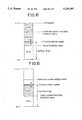
- FIGS. 1 and 8illustrate a driving control system for a vehicle according to a first embodiment of the present invention, wherein
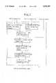
- FIG. 1is a block diagram illustrating the entire arrangement
- FIG. 2is a block diagram of a control section
- FIG. 3is a flow sheet illustrating the operation
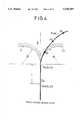
- FIG. 4is a diagram for explaining the operation at a low vehicle speed
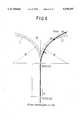
- FIG. 5is a diagram for explaining the operation at a high vehicle speed
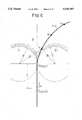
- FIG. 6is a diagram for explaining the operation when a road is within a passable area
- FIG. 7is a diagram for explaining the operation when a road is out of the passable area.
- FIG. 8is a diagram for explaining a method for determining a passable vehicle speed.
- FIGS. 9 to 20illustrate a driving control system for a vehicle according to a second embodiment of the present invention, wherein
- FIG. 9is a block diagram illustrating the entire arrangement
- FIG. 10(a), 10(b)are jointly a diagram for explaining the outline of the operation
- FIGS. 11 to 13are a flow than illustrating the operation
- FIG. 14is a diagram for explaining a method for determining a detection area
- FIG. 15is a diagram for explaining another method for determining a detection area
- FIG. 16is a diagram for explaining a method for calculating a target vehicle speed
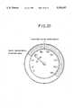
- FIG. 17is a schematic view of an instrument panel
- FIG. 18is a diagram illustrating one embodiment of an alarm means
- FIG. 19is a diagram illustrating another embodiment of an alarm means.
- FIG. 20is a diagram illustrating a further embodiment of an alarm means.
- reference character NVis a navigation system for an automobile, which includes therein a well-known inertia navigating device 1, a map information output means 2 1 using an IC card or CD-ROM, and a control section 3 for various calculations which will be described hereinafter.
- the inertia navigating device 1receives signals from a vehicle speed detecting means 6 1 and a yaw rate detecting means 7 1 in addition to a vehicle position information, a road information, a traffic information and the like from a satellite communication device 4 1 or a proximity communication device 5 1 .
- the navigation device 1calculates a current position of a subject vehicle, or a path to a goal, on the basis of the signals and road data from the map information output means 2 1 , and displays them on CRT 9 1 through a man-machine interface 8.
- the control section 3performs various calculations, which will be described hereinafter, in real time on the basis of outputs from the map information output means 2 1 and the vehicle speed detecting means 6 1 .
- Reference character D 1is a vehicle speed control unit which includes therein an image forming means 11, an alarm means 12 1 and a vehicle speed regulating means 13 1 .
- the image forming means 11includes, for example, a head-up display, and displays a road map, a vehicle position, a corner-passable vehicle speed or the like.
- the alarm means 12 1includes an acoustical means such as a buzzer or chime and gives an alarm to a driver to reduce the travel speed.
- the vehicle speed regulating means 13 1includes a brake device or an automatic cruise device and regulates the vehicle speed, so that the vehicle can pass through a corner.
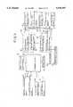
- the control section 3 of the navigation system NVincludes a minimum turnable radius calculating means M1 for calculating a minimum turnable radius R of a vehicle on the basis of a vehicle speed V 0 ; a temporary or transient vehicle-position calculating means M2 for calculating a temporary or transient vehicle position P 1 which is in front of the vehicle position P 0 in the traveling direction by using a vehicle speed V 0 and the vehicle position P 0 ; a passable area determining means M3 for determining a vehicle-passable area A from the minimum turnable radius R of the vehicle and the temporary vehicle position P 1 ; a passability/impassability judging means M4 for judging whether or not the vehicle is passable through a corner, from road position data N and the vehicle-passable area A; a maximum turning-radius calculating means M5 for calculating a maximum turning-radius R' such that the position data N is included in the passable area A if the vehicle can not pass the corner; a passable vehicle-speed calculating
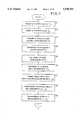
- a current position P 0 (X 0 , Y 0 ) of the subject vehicleis detected by the inertia navigating device 1 of the navigation system NV (at a step S1), and a current vehicle speed V 0 is detected by the vehicle speed detecting means 6 1 (at a step S2).
- a preread distance Lis calculated on the basis of the vehicle speed V 0 (at a step S3), and the temporary vehicle position calculating means M2 calculates a temporary vehicle position P 1 (X 1 , Y 1 )from the vehicle position P 0 (X 0 , Y 0 )and the preread distance L (at a step S4).
- the temporary vehicle position P 1 (X 1 , Y 1 )is a reference position in which it is judged whether or not the vehicle is passable through the corner, and the passable vehicle speed V MAX enabling the vehicle to pass through the corner is determined.
- the preread distance Lis determined at a larger value, as the vehicle speed V 0 is larger, so that a sufficient speed-reduction distance can be insured when the current vehicle speed V 0 is too large such that the vehicle is impassable through a corner which is in front of the temporary vehicle position P 1 (X 1 , Y 1 ).
- the minimum turnable radius calculating means M1searches, on the map, a minimum turnable radius R on the basis of the vehicle speed V 0 (at a step S5).
- This minimum turnable radius Ris larger at a larger vehicle speed V 0 and smaller at a smaller vehicle speed V 0 .
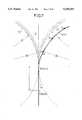
- a passable area Ais determined by the passable area determining means M3. More specifically, two same-radius circular arcs C 1 and C 2 having a radius equal to the minimum turnable radius R are defined so as to contact with each other at the temporary vehicle position P 1 (X 1 , Y 1 ), and the passable area A is established outside the two circular arcs C 1 and C 2 (at a step S6).
- the minimum turnable radius Ris smaller when the vehicle speed V 0 is smaller, as shown in FIG. 4, and hence, the passable area A is wider.
- the minimum turnable radius Ris larger when the vehicle speed V 0 is larger, as shown in FIG. 5, and hence, the passable area A is narrower.
- the node points Nare present in the passable area A as shown in FIG. 4, it is decided that the vehicle is passable through the corner at the current vehicle speed V 0 .
- the node points Nare out of the passable area A as shown in FIG. 5, it is decided that the vehicle is impassable through the corner at the current vehicle speed V 0 .
- the node pointsare established at closer distances spaced apart from one another, as a road has a smaller radius of curvature.
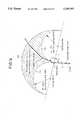
- Whether the node points N are inside or outside the passable area Ais judged in the passability/impassability judging means M4 in a following manner: If both of distances B 1 and B 2 between the centers of the two circular arcs C 1 and C 2 having the radius R and the node point N are larger than a radius R, as shown in FIG. 6, it is decided that the node point N is inside the passable area A, and the vehicle is passable through the node point N at the current vehicle speed V 0 . On the other hand, if one of the distances B 1 and B 2 (e.g., B 2 ) between the centers of the two circular arcs C 1 and C 2 having the radius R and the node point N is smaller than a radius R, as shown in FIG. 7, it is decided that the node point N is outside the passable area A, and the vehicle is impassable through the node point N at the current vehicle speed V 0 .
- the distances B 1 and B 2e.g., B 2
- a maximum turning radius R' required for the vehicle to pass the corneris calculated in the maximum turning radius calculating means M5 (at a step S8).
- the maximum turning radius R'is determined as a radius R' of circular arcs C 1 ' and C 2 ' inside which all the node points are not present (see FIG. 8). Therefore, if the vehicle speed is reduced down to a speed at which the vehicle can be turned with the maximum turning radius R', the vehicle can pass through the corner.
- a vehicle speed V 1 at which the vehicle can be turned with the maximum turning radius R'is calculated in the passable vehicle-speed calculating means M6 (at a step S9), and such vehicle speed V 1 is determined as a passable vehicle speed V MAX (at a step S10).
- the processingis advanced to the step S10, at which the current vehicle speed V 0 , as it is, is determined as the passable vehicle speed V MAX .
- the current vehicle speed V 0is compared with the passable vehicle speed V MAX , i.e., if the vehicle is impassable through the corner, the vehicle speed V 0 is adjusted by the vehicle speed regulating means 13 1 of the vehicle control unit D 1 ,so that it is reduced to a level equal to or less than the passable vehicle speed V MAX , until the vehicle reaches the temporary vehicle position P 1 (at a step S12). This enables the vehicle to reliably pass through the corner.
- the alarm means 12 1can be used in combination. More specifically, when the current vehicle speed V 0 is, for example, within 1.2 times the passable vehicle speed V MAX , the alarm means 12 1 may be operated to provide only an alarm. When the vehicle speed V 0 reaches at least 1.2 times the passable vehicle speed V MAX , the vehicle speed regulating means 13 1 may be operated to reduce the vehicle speed.
- the vehicleis enabled to pass through the corner at a proper vehicle speed by performing the reduction of the vehicle speed by the alarm means 12 1 and/or the vehicle speed regulating means 13 1 .
- the preread distance L and the minimum turnable radius Rare determined on the basis of the vehicle speed V 0 , they can be corrected on the basis of operational conditions such as the weight of a vehicle body and the like and/or driving environments such as a frictional coefficient of a road and the like. For example, when the weight of a vehicle body is large and the frictional coefficient of a road is small, if the preread distance L is set at a large value, and the minimum turnable radius R is set at a large value, a more proper judgment and control can be performed.
- step S11 of the flow chart in FIG. 3i.e., if the vehicle is passable through the corner at the current vehicle speed V 0 , it is possible to deter:mine that the vehicle can pass through the corner, no matter how many km/hr the speed may be reduced from the current vehicle speed V 0 .
- the passable vehicle speeds V MAX changed momentarilycan be stored in a memory while being sequentially renewed over a predetermined time, and the current vehicle speed V 0 can be compared with the maximum value of the stored passable vehicle speeds V MAX .
- FIGS. 9 to 16A driving control system for a vehicle according to a second embodiment of the present invention will now be described in connection with FIGS. 9 to 16.
- reference character 22is a navigation system for an automobile.
- a map information output device 2 2 using an IC card or CD-ROMis connected to the navigation system 22.
- Various information from a satellite communication device 4 2 and a proximity communication device 5 2 and signals from a vehicle speed detecting means 6 2 and a yaw rate detecting means 7 2are supplied to the navigation system 22.
- a display means 9 2 including CRTis connected to the navigation system 22. A path to a goal and a vehicle position on a map are displayed on the display means 9 2 .
- Map data and information such as the vehicle positionare supplied from the navigation system 22 to a vehicle speed control unit D 2 .
- the vehicle positionis detected by a vehicle position detecting means such as an inertia navigating device. Signals are supplied to the vehicle speed control unit D 2 from the vehicle speed detecting means 6 2 , a road surface condition detecting means 14 for detecting a frictional coefficient of a road, a road gradient detecting means 15 for detecting an inclination (up- and down-grades and the degrees thereof) of a road, a rainfall detecting means 16 used in an automatic wiper device or the like, and a peripheral-light detecting means 17 used in an auto-light device or the like.
- a vehicle position detecting meanssuch as an inertia navigating device.
- Signalsare supplied to the vehicle speed control unit D 2 from the vehicle speed detecting means 6 2 , a road surface condition detecting means 14 for detecting a frictional coefficient of a road, a road gradient detecting means 15 for detecting an inclination
- an alarm means 12 2 and a speed-reducing means 13 2 as a vehicle speed regulating meansare connected to the vehicle speed control unit D 2 .
- the alarm means 12 2may be a means for giving a visual alarm using a light emitting diode or the like which will be described hereinafter.
- the speed-reduction means 13 2is comprised of a throttle actuator connected to an engine control ECU for adjusting the throttle opening degree, and a brake actuator connected to a brake control ECU for actuating a brake device.
- the vehicle speed control unit D 2includes a judging-section determining means 18 for determining an investigating section L 1 , an alarming section L 2 and a speed-reducing; section L 3 ; a judgment-execution determining means 19 for determining whether or not a judgment of passability/impassability in the alarm section L 2 and the speed-reduction section L 3 should be carried out on the basis of the decision that it is possible; or impossible for the vehicle to pass through a road in the investigating section L 1 ; an alarming-execution determining means 20 for operating the alarm means 12 2 on the basis of the decision that it is possible or impossible for the vehicle to pass the road in the alarming section L 2 ; and a speed-reducing-execution determining means 21 for actuating the speed-reducing means 13 2 on the basis of the decision that it is possible or impossible for the vehicle to pass through the road in the speed-reducing section L 3 .
- the vehicle speed control unit D 2calculates each of signals from the navigation system 22, the vehicle speed detecting means 6 2 , the road surface condition detecting means 14, the rainfall detecting means 16 and the peripheral-light detecting means 17; operates the alarm means 12 2 to give an alarm to a driver, and actuates the speed-reduction means 13 2 to automatically reduce the speed of the vehicle.
- Coordinates N of a plurality of node points on a road which indicate a travel path for the subject vehicle, and coordinates P 0 of a current position of the vehicleare included in map data supplied from the navigation system 22 to the vehicle speed control unit D 2 .
- An investigating section L 1 , an alarming section L 2 and a speed-reducing section L 3 each having a predetermined length determined in accordance with the vehicle speedare established on a road forward in a traveling direction on the basis of a vehicle position P 0 .
- a node point lying at a front end of the investigating section L 1 farthest from the subject vehicleis determined as a first temporary vehicle position Pn; a node point lying at a front end of the intermediate alarming section L 2 is determined as a second temporary vehicle position Pk, and a node point lying at a front end of the speed-reducing section L 3 nearest to the subject vehicle is determined as a third temporary vehicle position Pj.
- the investigating section L 1constitutes a first section in this embodiment, and the alarming section L 2 and the speed-reducing section L 3 together constitute a second section in this embodiment.
- the alarm means 12 2is actuated to suggest the driver to conduct the reduction of speed, and it is judged whether or not the vehicle is passable through the speed-reducing section L 3 (i.e., between the current position P 0 and the third temporary vehicle position Pj) at the current vehicle speed. If it is decided that there is a hindrance to the passage, the speed-reduction means 13 2 is actuated to automatically reduce the speed of the vehicle.
- a road surface condition correcting factor K 1is calculated on the basis of a road surface frictional coefficient detected by the road surface condition detecting means 14; a road gradient correcting factor K 2 is calculated from a road gradient detected by the road gradient detecting means 15; a rainfall correcting factor K 3 is calculated from a rainfall condition detected by the rainfall detecting means 16; and a peripheral-light correcting factor K 4 is calculated from a brightness detected by the peripheral-light detecting means 17 (steps Q3 to Q6).
- These correcting factors K 1 to K 4are determined, for example, by a map-searching.
- a first set lateral acceleration a 1 for determining a first detection area A 1 for judging whether or not an alarming is required, and a second set lateral acceleration ⁇ 2 for determining a second detection area A 2 for judging whether or not a reduction of speed is required,are determined (at a step Q7).
- the first and second set lateral accelerations ⁇ 1 and ⁇ 2are intended to define a limit value of lateral acceleration when the vehicle passes through a node point on a road, and they are determined so that ⁇ 2 > ⁇ 1 is established.
- the first and second set lateral accelerations ⁇ 1 and ⁇ 2are determined, their values are corrected on the basis of the road surface condition correcting factor K 1 , the road gradient correcting factor K 2 , the rainfall correcting factor K 3 and the peripheral-light correcting factor K 4 . More specifically, when the vehicle is in a condition in which it is difficult for the vehicle to sharply turn such as when the road surface frictional coefficient is small, when the road has a downgrade, when it is raining, or when the environment is dark, the values of the first and second set lateral accelerations ⁇ 1 and ⁇ 2 are corrected to small values.
- a first set deceleration ⁇ 1 for determining the investigating section L 1 and the alarming section L 2 , and a second set deceleration ⁇ 2 for determining the speed-reducing section L 3are determined (at a step Q8).
- Each of the first and second set decelerations ⁇ 1 and ⁇ 2is a deceleration required to sufficiently reduce the speed of the vehicle within a predetermined time, until the vehicle reaches the second temporary vehicle position Pk or the third vehicle position Pj from the current position P 0 .
- the first and second set decelerations ⁇ 1 and ⁇ 2are determined, their values are corrected on the basis of the road surface condition correcting factor K 1 , the road gradient correcting factor K 2 , the rainfall correcting factor K 3 and the peripheral-light correcting factor K 4 . More specifically, when the vehicle is in a condition in which it is difficult to rapidly reduce the speed of the vehicle, such as when the road surface frictional coefficient is small, when the road has a downgrade, when it is raining, or when the environment is dark, the values of the first and second set decelerations ⁇ 1 and ⁇ 2 are corrected to small values.
- the road surface condition, the road gradient, the rainfall condition and the environment conditionare taken into consideration in the present embodiment. But in addition to such factors, a driver condition may also be taken into consideration.
- a driver's fatigued condition or a driver's drowsiness conditioncan be judged from the monitored movements of driver's eyeballs and eyelids, or from a driver's monitored heart rate, a driver's monitored respiratory rate or the like, and on the basis thereof, the first and second set lateral accelerations ⁇ 1 and ⁇ 2 and the first and second set decelerations ⁇ 1 and ⁇ 2 can be corrected to values for safety, respectively.
- a first set time t 1 which the vehicle requires to reach the second temporary vehicle position Pk from the current position P 0 , and a second set time t 2 which the vehicle requires to reach the third temporary vehicle position Pj from the current position P 0are determined (at a step Q9).
- This investigating section L 1corresponds to a distance required to stop the vehicle when the speed-reduction from the vehicle speed V 0 is conducted with the first set deceleration ⁇ 1 .
- This alarming section L 2corresponds to a distance through which the vehicle travels within the first set time, when the speed-reduction from the vehicle speed V 0 is conducted with the first set deceleration ⁇ 1 .
- This speed-reducing section L 3corresponds to a distance through which the vehicle travels within the second set time t 2 , when the speed-reduction from the vehicle speed V 0 is conducted with the second set deceleration ⁇ 2 .
- crank or the junctionis not detected at the step Q15 and the corner is not detected at the step Q16, or if the right-turning or left-turning is not conducted at such intersection or the like at the step Q17 and the corner is not detected at the step Q16 even if the intersection, the crank and/or the junction are/is detected at the step Q15, i.e., if the road within the investigating section L 1 in which the vehicle travels is a straight road, it is decided that the vehicle is passable through the investigating section L 1 without giving an alarm and without conducting the speed-reduction, and the system operation returns to the start of a program.
- step Q15If the intersection, the crank and/or the junction is detected at the step Q15 and the right-turning or the left-turning is conducted at such intersection or the like at the step Q17, or if the corner is detected at the step Q16, i.e., if the road within the investigating section L 1 in which the vehicle travels is not a straight road, it is decided that it can be required to give an alarm and conduct the speed-reduction, moving to a step Q18 in the flow chart portion shown in FIG. 13.
- FIG. 14illustrates a method for determining the first detection area A 1 .
- a line cbisecting an angle formed by two lines: a line segment a connecting the node point within the alarming section L 2 and a forward node point and a line segment b connecting the node point and a rearward node point is described.
- a minimum turning radius R 1is calculated on the basis of the current vehicle speed V 0 and the first set lateral acceleration ⁇ 1 according to an expression, R 1 V 0 2 / ⁇ 1 .
- two circular arcs C 1 and C 2having a turning center on the bisecting line c and passing the node point are described.
- an obliquely-lined area surrounded by a circular arc C 3 of a radius 2R 1 about the node point and by the two circular arcs C 1 and C 2is determined as the first detection area A 1 .
- FIG. 15illustrates another method for determining the first detection area A 1 .
- a point of intersection between a line d for vertically bisecting a line segment a connecting the node point within the alarming section L 2 and a forward node point and a line segment e bisecting a line segment b connecting the node point and a rearward node pointis first determined.
- a straight line f connecting such point of intersection and the node pointis described.
- the minimum turning radius R 1 of the first detection area A 1 determined in the above mannercorresponds to a minimum turning radius at which the vehicle can be turned at a lateral acceleration equal to or less than the first set lateral acceleration ⁇ 1 , when the vehicle enters the node point at the current vehicle speed V 0 . Therefore, if the forward node point is inside the first detection area A 1 , the vehicle is passable through the node point at a lateral acceleration equal to or less than the first set lateral acceleration ⁇ 1 . On the other hand, if the forward node point is outside the first detection area A 1 , the vehicle is impassable through the node point at a lateral acceleration equal to or less than the first set lateral acceleration ⁇ 1 .
- the alarm means 12 2is actuated to alarm the driver to conduct the speed-reduction, and this alarming is stopped after a lapse of the first set time t 1 (at steps Q22 and Q23).
- the alarm means 12 2will be described in detail hereinafter.
- a second detection area A 2is established for each node point within the speed-reducing section L 3 (at a step Q24).
- the minimum turning radius R 2 of the second detection area A 2is smaller than the minimum turning radius R 1 of the first detection area A 1 (R 2 ⁇ R 1 ).
- the minimum turning radius R 2 of the second detection area A 2 established in the above mannercorresponds to a minimum turning radius at which the vehicle can be turned at a lateral acceleration equal to or less than the second set lateral acceleration ⁇ 2 , when the vehicle enters the node point at the current vehicle speed V 0 . If the forward node point is inside the second detection area A 2 , the vehicle is passable through the node point at a lateral acceleration equal to or less than the second set lateral acceleration ⁇ 2 . On the other hand, if the forward node point is outside the second detection area A 2 , the vehicle is impassable through the node point at a lateral acceleration equal to or less than the second set lateral acceleration ⁇ 2 .
- step Q25If the forward node point is outside the second detection area A 2 (at a step Q25), it is decided that the vehicle is impassable through the speed-reducing area L 3 at the current vehicle speed V 0 , and the speed-reducing means 13 2 is actuated to automatically conduct the speed-reduction which is stopped after a lapse of the second set time t 2 (steps Q26 and Q27).
- the inventionprovides a reduction in size of a calculating means used therein and also increases the speed of other calculations made thereby.
- a fine control of the vehicle speedcan be performed from the alarming to the speed-reduction in accordance with the approaching condition of the vehicle to a corner or the like.
- the time of operation of the alarm means 12 2 and the time of operation of the speed-reducing means 13 2have been defined by the first and second set times t 1 and t 2 previously set in the above embodiment, but they can be determined in other manners such as the following:
- a first target vehicle speed V 1 as a vehicle speed permitting the vehicle to pass through such node pointis calculated and stored in a memory.
- a second target vehicle speed V 2as a vehicle speed permitting the vehicle to pass through such node point is calculated in the same manner as that shown in FIG. 8.
- a first target vehicle speed V 1is calculated in the manner described above for all the node points within the alarming section L 2 , and is stored in the memory. Then, a deceleration required to reduce the current vehicle speed V 0 to the first target vehicle speed V 1 before the vehicle reaches each node point is calculated. When such deceleration exceeds the first set deceleration ⁇ 1 , the alarm means 12 2 is actuated. Likewise, the second target vehicle speed V 2 is calculated for all the node points within the speed-reducing section L 3 , and is stored in the memory. When a deceleration required to reduce the current vehicle speed V 0 to the second target vehicle speed V 2 before the vehicle reaches each node point, exceeds the second set deceleration ⁇ 2 , the speed-reducing means is actuated.
- the alarm means 12 2 including a light-emitting diodeis formed into a lengthwise long bar and mounted at an easily visible place between a speedometer 23 and a tachometer 24 mounted in an instrument panel.
- the alarm means 12 2includes a "blue” region, a "yellow” region and a “red” region provided in sequence from the bottom to the top.
- the boundary between the "blue” region and the “yellow” regioncorresponds to an alarm threshold value at which the alarm means 12 2 is operated
- the boundary between the "yellow” region and the “red” regioncorresponds to an automatic speed-reduction threshold value at which the speed-reducing means 13 2 is operated.
- Each of the alarm threshold value and the automatic speed-reduction threshold valueis determined as a fixed value which is not dependent on the curvature of a corner in this embodiment, but they can be varied depending upon, for example, a road surface condition and a driver's skill.
- a region of the alarm means 12 2 from a lower end to a current vehicle speedis lit by an increase in vehicle speed, and when the vehicle speed exceeds the alarm threshold value, a portion of the "yellow” region between the alarm threshold value and the current value is lit, so that the degree of excess of the current vehicle speed can be easily recognized in accordance with the area of the lit portion. If the vehicle speed is further excessive to exceed the automatic speed-reduction threshold value, a portion of the "red" region between the automatic speed-reduction threshold value and the current vehicle speed is lit together with the entire "yellow” region, so that the degree of excess of the current vehicle speed can be easily recognized in accordance with the area of the lit portion.
- FIG. 19illustrates another embodiment of an alarm means 12 2 .
- this alarm means 12 2a region from its lower end to a current vehicle speed is lit by an increase in vehicle speed. In the lit region, a portion below an alarm (speed-reduction) threshold value is lit “blue", and a portion above the alarm (speed-reduction) threshold value is lit “red”.
- the alarm (speed-reduction) threshold valueis varied vertically depending on the curvature of a corner.
- FIG. 20illustrates a further embodiment of an alarm means 12 2 .
- an outer peripheral portion around a dial of a speedometer 23is formed of a light-emitting diode.
- a portion indicating a higher speed than the alarm (speed-reduction) threshold value(a variable value dependent upon the curvature of a corner) is lit as a "red" region. Therefore, the excess amount of the vehicle speed can be visually recognized by a distance between the position of a pointer indicating a current speed and a starting end of the "red” region. If the starting end of the lit "red" region is moved toward a lower-speed side as the vehicle approaches an entrance of a corner, it is possible to permit the driver to further effectively recognize the emergence degree.
- an alarmcan be reliably given by giving a visual alarm by lighting of the light-emitting diode, even when an auditorily handicapped driver is driving the vehicle, or even when the sound volume of an audio device is too large to provide a sufficient effect by an alarm means such as a chime or a buzzer.
Landscapes
- Physics & Mathematics (AREA)
- General Physics & Mathematics (AREA)
- Engineering & Computer Science (AREA)
- Radar, Positioning & Navigation (AREA)
- Remote Sensing (AREA)
- Life Sciences & Earth Sciences (AREA)
- Atmospheric Sciences (AREA)
- Automation & Control Theory (AREA)
- Traffic Control Systems (AREA)
- Navigation (AREA)
- Control Of Driving Devices And Active Controlling Of Vehicle (AREA)
Abstract
Description
1. Field of the Invention
The present invention relates to a driving control system for a vehicle, which enables a vehicle to pass through a corner or the like on a road at an appropriate vehicle speed by utilizing a so-called navigation system including a map information output means for outputting a map, and a vehicle position detecting means for detecting a vehicle position on the map.
2. Description of Relevant Art
There is a conventionally known driving information display apparatus utilizing a navigation system, as described, for example, in Japanese Patent Application Laid-open No. 89298/85.
Such driving information display apparatus is capable of not only displaying a map and a vehicle position on a display surface, but also detecting a corner through which the vehicle cannot pass at a current vehicle speed over a given section in a traveling direction of the vehicle on the basis of the travel distance and the radius of curvature of the corner on a road on the map; calculating an appropriate vehicle speed at which the vehicle can properly pass through such corner, and displaying such information to attract a driver's attention.
In the above known technique, the accuracy of the appropriate vehicle speed is largely dependent upon the accuracy of calculation of the radius of curvature of a corner on a road, i.e., the accuracy of the map provided by the navigation system. However, the accuracy of the map provided by the known navigation system is insufficient for correctly calculating the radius of curvature of the corner. Moreover, the above known technique suffers from a problem that the calculation of the radius of curvature of the corner is complicated and, hence, a calculating device of a large capacity is required.
It is an object of the present invention to provide a control system which enables the travel of a vehicle to be properly controlled by accurately judging whether or not it is possible for the vehicle to pass through a corner on a road without calculation of the radius of curvature of the corner, and accurately determining a vehicle speed at which the vehicle can safely pass through the corner.
To achieve the above object, according to a first aspect and feature of the present invention, there is provided a driving control system for a vehicle, comprising a map information output means for outputting a map, a vehicle position detecting means for detecting a vehicle position of a subject vehicle on the map, a vehicle speed detecting means for detecting a vehicle speed, a passable area determining means for determining a passable area on the map which is safely passable by the vehicle based on the detected vehicle speed, a passability/impassability judging means for deciding that the vehicle is safely passable through a portion or corner of a road which is in front of the vehicle position in a traveling direction of the vehicle when a road is included in the passable area on a map, and all of the discussed components being operatively interconnected.
With the above-described system, the passable area on the map is determined on the basis of the vehicle speed; and the road section which is in front of the vehicle position is compared with the passable area, and when the road is included in the passable area, it is decided that the vehicle is passable through the road section. Therefore, it is possible to properly judge whether or not the vehicle is passable through the road section by a simple calculation without a complicated and poor-accuracy calculation of the radius of curvature of a road.
In addition, according to a second aspect and feature of the present invention, there is provided a driving control system for a vehicle, comprising a map information output means for outputting a map, a vehicle position detecting means for detecting a vehicle position of a subject vehicle on the map, a maximum turnable radius determining means for determining, on the basis of a road portion which is in front of the vehicle position in a traveling direction on the map, a maximum turnable radius required for the vehicle to safely pass through the road portion, a passable vehicle speed calculating means for calculating a passable vehicle speed based on the maximum turnable radius, and all of the discussed components being operatively interconnected.
With the above-described system, the maximum turnable radius required for the vehicle to pass through the road section which is in front of the vehicle position in the traveling direction on the map is determined, and the passable vehicle speed is calculated on the basis of the maximum turnable radius. Therefore, it is possible to determine a passable vehicle speed by a simple calculation without calculation of the radius of curvature of a complex road.
Further, according to a third aspect and feature of the present invention, there is provided a driving control system for a vehicle, comprising a map information output means for outputting a map, a vehicle position detecting means for detecting a vehicle position of a subject vehicle on the map, a vehicle speed detecting means for detecting a vehicle speed, a judging-section determining means for establishing a first section having a predetermined range and a second section having a range narrower than said predetermined range on a road in front of the vehicle position in a traveling direction, a judgment-execution determining means for judging whether or not the vehicle is safely passable through a road in the first section on the basis of the detected vehicle speed and a curved condition of the road on the map, and for determining, on the basis of such judgment, whether or not the judgment of the passability or impassability of the vehicle through a road in the second section should be conducted, a passability/impassability judging means for judging whether or not the vehicle is safely passable through the road in the second section based on the detected vehicle speed and the curved condition of the road on the map, when it is decided by the judgment-execution determining means that the judgment of the passability or impassability of the vehicle through the road in the second section should be conducted, providing at least one of a means for an alarm and a vehicle speed adjustment based on the judgment of whether or not the vehicle is passable through the road in the second section, and all of the discussed components being operatively interconnected.
With the above-described system, for example, when the vehicle is traveling on a road having a long straight portion which provides no hindrance to the vehicle's passage thereover, as does a freeway, it is not necessary to conduct the judgment of whether or not the vehicle is passable through the road in the second section and, hence, it is possible to reduce the calculation quantity which must be made by the system. This makes it possible to provide a reduction in size of the calculating device and, in its turn, of the entire control unit and to improve the speed of another or subsequent calculation by the system.
The above and other objects, features and advantages will become apparent from the following description of preferred embodiments, taken in conjunction with the accompanying drawings.
FIGS. 1 and 8 illustrate a driving control system for a vehicle according to a first embodiment of the present invention, wherein
FIG. 1 is a block diagram illustrating the entire arrangement;
FIG. 2 is a block diagram of a control section;
FIG. 3 is a flow sheet illustrating the operation;
FIG. 4 is a diagram for explaining the operation at a low vehicle speed;
FIG. 5 is a diagram for explaining the operation at a high vehicle speed;
FIG. 6 is a diagram for explaining the operation when a road is within a passable area;
FIG. 7 is a diagram for explaining the operation when a road is out of the passable area; and
FIG. 8 is a diagram for explaining a method for determining a passable vehicle speed.
FIGS. 9 to 20 illustrate a driving control system for a vehicle according to a second embodiment of the present invention, wherein
FIG. 9 is a block diagram illustrating the entire arrangement;
FIG. 10(a), 10(b) are jointly a diagram for explaining the outline of the operation;
FIGS. 11 to 13 are a flow than illustrating the operation;
FIG. 14 is a diagram for explaining a method for determining a detection area;
FIG. 15 is a diagram for explaining another method for determining a detection area;
FIG. 16 is a diagram for explaining a method for calculating a target vehicle speed;
FIG. 17 is a schematic view of an instrument panel;
FIG. 18 is a diagram illustrating one embodiment of an alarm means;
FIG. 19 is a diagram illustrating another embodiment of an alarm means; and
FIG. 20 is a diagram illustrating a further embodiment of an alarm means.
A driving control system for a vehicle according to a first embodiment of the present invention will now be described in connection with FIGS. 1 to 8.
Referring to FIG. 1, reference character NV is a navigation system for an automobile, which includes therein a well-knowninertia navigating device 1, a map information output means 21 using an IC card or CD-ROM, and acontrol section 3 for various calculations which will be described hereinafter. Theinertia navigating device 1 receives signals from a vehicle speed detecting means 61 and a yaw rate detecting means 71 in addition to a vehicle position information, a road information, a traffic information and the like from a satellite communication device 41 or aproximity communication device 51. Then thenavigation device 1 calculates a current position of a subject vehicle, or a path to a goal, on the basis of the signals and road data from the map information output means 21, and displays them onCRT 91 through a man-machine interface 8. Thecontrol section 3 performs various calculations, which will be described hereinafter, in real time on the basis of outputs from the map information output means 21 and the vehicle speed detecting means 61.
Reference character D1 is a vehicle speed control unit which includes therein animage forming means 11, an alarm means 121 and a vehicle speed regulating means 131. Theimage forming means 11 includes, for example, a head-up display, and displays a road map, a vehicle position, a corner-passable vehicle speed or the like. The alarm means 121 includes an acoustical means such as a buzzer or chime and gives an alarm to a driver to reduce the travel speed. The vehicle speed regulating means 131 includes a brake device or an automatic cruise device and regulates the vehicle speed, so that the vehicle can pass through a corner.
As shown in FIG. 2, thecontrol section 3 of the navigation system NV includes a minimum turnable radius calculating means M1 for calculating a minimum turnable radius R of a vehicle on the basis of a vehicle speed V0 ; a temporary or transient vehicle-position calculating means M2 for calculating a temporary or transient vehicle position P1 which is in front of the vehicle position P0 in the traveling direction by using a vehicle speed V0 and the vehicle position P0 ; a passable area determining means M3 for determining a vehicle-passable area A from the minimum turnable radius R of the vehicle and the temporary vehicle position P1 ; a passability/impassability judging means M4 for judging whether or not the vehicle is passable through a corner, from road position data N and the vehicle-passable area A; a maximum turning-radius calculating means M5 for calculating a maximum turning-radius R' such that the position data N is included in the passable area A if the vehicle can not pass the corner; a passable vehicle-speed calculating means M6 for calculating a passable vehicle-speed VMAX on the basis of the maximum turning-radius R'; and a comparing means M7 for comparing the passable vehicle-speed VMAX with the vehicle speed V0. The vehicle speed control unit D1 is controlled on the basis of an output from the comparing means M7.
The operation of the driving control system according to the present invention having the above-described construction will be described below with reference to a flow chart in FIG. 3.
First, a current position P0 (X0, Y0) of the subject vehicle is detected by theinertia navigating device 1 of the navigation system NV (at a step S1), and a current vehicle speed V0 is detected by the vehicle speed detecting means 61 (at a step S2). Then, a preread distance L is calculated on the basis of the vehicle speed V0 (at a step S3), and the temporary vehicle position calculating means M2 calculates a temporary vehicle position P1 (X1, Y1)from the vehicle position P0 (X0, Y0)and the preread distance L (at a step S4). As shown in FIGS. 4 and 5, the temporary vehicle position P1 (X1, Y1)is a reference position in which it is judged whether or not the vehicle is passable through the corner, and the passable vehicle speed VMAX enabling the vehicle to pass through the corner is determined. The preread distance L is determined at a larger value, as the vehicle speed V0 is larger, so that a sufficient speed-reduction distance can be insured when the current vehicle speed V0 is too large such that the vehicle is impassable through a corner which is in front of the temporary vehicle position P1 (X1, Y1).
Then, the minimum turnable radius calculating means M1 searches, on the map, a minimum turnable radius R on the basis of the vehicle speed V0 (at a step S5). This minimum turnable radius R is larger at a larger vehicle speed V0 and smaller at a smaller vehicle speed V0.
Subsequently, a passable area A is determined by the passable area determining means M3. More specifically, two same-radius circular arcs C1 and C2 having a radius equal to the minimum turnable radius R are defined so as to contact with each other at the temporary vehicle position P1 (X1, Y1), and the passable area A is established outside the two circular arcs C1 and C2 (at a step S6). The minimum turnable radius R is smaller when the vehicle speed V0 is smaller, as shown in FIG. 4, and hence, the passable area A is wider. On the other hand, the minimum turnable radius R is larger when the vehicle speed V0 is larger, as shown in FIG. 5, and hence, the passable area A is narrower.
Then, the map information output means 21 establishes a plurality of node points N=N1, N2, N3, . . . on a road on the basis of the road position data read from the IC card or the CD-ROM, and the passability/impassability judging means M4 judges whether or not these node points are present in the passable area A (at a step S7). When the node points N are present in the passable area A as shown in FIG. 4, it is decided that the vehicle is passable through the corner at the current vehicle speed V0. On the other hand, when the node points N are out of the passable area A as shown in FIG. 5, it is decided that the vehicle is impassable through the corner at the current vehicle speed V0. The node points are established at closer distances spaced apart from one another, as a road has a smaller radius of curvature.
Whether the node points N are inside or outside the passable area A is judged in the passability/impassability judging means M4 in a following manner: If both of distances B1 and B2 between the centers of the two circular arcs C1 and C2 having the radius R and the node point N are larger than a radius R, as shown in FIG. 6, it is decided that the node point N is inside the passable area A, and the vehicle is passable through the node point N at the current vehicle speed V0. On the other hand, if one of the distances B1 and B2 (e.g., B2) between the centers of the two circular arcs C1 and C2 having the radius R and the node point N is smaller than a radius R, as shown in FIG. 7, it is decided that the node point N is outside the passable area A, and the vehicle is impassable through the node point N at the current vehicle speed V0.
Even if, for example, the node points N1 and N3 are inside the passable area A, if the node point N2 is outside the passable area A, as shown in FIG. 8, the vehicle is impassable through the node point N at the current vehicle speed V0. Therefore, to permit the vehicle to pass through the corner at the current vehicle speed V0, it is required that all the node points N are inside the passable area A.
When it is decided at the step S7 that the vehicle is impassable through the corner, a maximum turning radius R' required for the vehicle to pass the corner is calculated in the maximum turning radius calculating means M5 (at a step S8). The maximum turning radius R' is determined as a radius R' of circular arcs C1 ' and C2 ' inside which all the node points are not present (see FIG. 8). Therefore, if the vehicle speed is reduced down to a speed at which the vehicle can be turned with the maximum turning radius R', the vehicle can pass through the corner.
A vehicle speed V1 at which the vehicle can be turned with the maximum turning radius R' is calculated in the passable vehicle-speed calculating means M6 (at a step S9), and such vehicle speed V1 is determined as a passable vehicle speed VMAX (at a step S10). When it is decided at the step S7 that the vehicle is passable through corner, the processing is advanced to the step S10, at which the current vehicle speed V0, as it is, is determined as the passable vehicle speed VMAX. The current vehicle speed V0 is compared with the passable vehicle speed VMAX, i.e., if the vehicle is impassable through the corner, the vehicle speed V0 is adjusted by the vehicle speed regulating means 131 of the vehicle control unit D1,so that it is reduced to a level equal to or less than the passable vehicle speed VMAX, until the vehicle reaches the temporary vehicle position P1 (at a step S12). This enables the vehicle to reliably pass through the corner.
It should be noted that in reducing the vehicle speed V0 to a level equal to or less than the passable vehicle speed VMAX, the alarm means 121 can be used in combination. More specifically, when the current vehicle speed V0 is, for example, within 1.2 times the passable vehicle speed VMAX, the alarm means 121 may be operated to provide only an alarm. When the vehicle speed V0 reaches at least 1.2 times the passable vehicle speed VMAX, the vehicle speed regulating means 131 may be operated to reduce the vehicle speed.
Without carrying out the complicated and low-accuracy calculation of a radius of curvature of a corner, it is judged whether or not the vehicle is passable through the corner. When the vehicle is impassable through the corner at the current vehicle speed, the vehicle is enabled to pass through the corner at a proper vehicle speed by performing the reduction of the vehicle speed by the alarm means 121 and/or the vehicle speed regulating means 131.
In the driving control system for the vehicle according to the first embodiment, when the preread distance L and the minimum turnable radius R are determined on the basis of the vehicle speed V0, they can be corrected on the basis of operational conditions such as the weight of a vehicle body and the like and/or driving environments such as a frictional coefficient of a road and the like. For example, when the weight of a vehicle body is large and the frictional coefficient of a road is small, if the preread distance L is set at a large value, and the minimum turnable radius R is set at a large value, a more proper judgment and control can be performed.
If a "NO" determination is made at the step S11 of the flow chart in FIG. 3, i.e., if the vehicle is passable through the corner at the current vehicle speed V0, it is possible to deter:mine that the vehicle can pass through the corner, no matter how many km/hr the speed may be reduced from the current vehicle speed V0.
Further, the passable vehicle speeds VMAX changed momentarily can be stored in a memory while being sequentially renewed over a predetermined time, and the current vehicle speed V0 can be compared with the maximum value of the stored passable vehicle speeds VMAX.
A driving control system for a vehicle according to a second embodiment of the present invention will now be described in connection with FIGS. 9 to 16.
In FIG. 9,reference character 22 is a navigation system for an automobile. A mapinformation output device 22 using an IC card or CD-ROM is connected to thenavigation system 22. Various information from a satellite communication device 42 and aproximity communication device 52 and signals from a vehicle speed detecting means 62 and a yaw rate detecting means 72 are supplied to thenavigation system 22. A display means 92 including CRT is connected to thenavigation system 22. A path to a goal and a vehicle position on a map are displayed on the display means 92.
Map data and information such as the vehicle position are supplied from thenavigation system 22 to a vehicle speed control unit D2. The vehicle position is detected by a vehicle position detecting means such as an inertia navigating device. Signals are supplied to the vehicle speed control unit D2 from the vehicle speed detecting means 62, a road surface condition detecting means 14 for detecting a frictional coefficient of a road, a road gradient detecting means 15 for detecting an inclination (up- and down-grades and the degrees thereof) of a road, a rainfall detecting means 16 used in an automatic wiper device or the like, and a peripheral-light detecting means 17 used in an auto-light device or the like.
Further, an alarm means 122 and a speed-reducing means 132 as a vehicle speed regulating means are connected to the vehicle speed control unit D2. In addition to a means for giving an acoustic alarm using a chime or a buzzer, the alarm means 122 may be a means for giving a visual alarm using a light emitting diode or the like which will be described hereinafter. The speed-reduction means 132 is comprised of a throttle actuator connected to an engine control ECU for adjusting the throttle opening degree, and a brake actuator connected to a brake control ECU for actuating a brake device.
The vehicle speed control unit D2 includes a judging-section determining means 18 for determining an investigating section L1, an alarming section L2 and a speed-reducing; section L3 ; a judgment-execution determining means 19 for determining whether or not a judgment of passability/impassability in the alarm section L2 and the speed-reduction section L3 should be carried out on the basis of the decision that it is possible; or impossible for the vehicle to pass through a road in the investigating section L1 ; an alarming-execution determining means 20 for operating the alarm means 122 on the basis of the decision that it is possible or impossible for the vehicle to pass the road in the alarming section L2 ; and a speed-reducing-execution determining means 21 for actuating the speed-reducing means 132 on the basis of the decision that it is possible or impossible for the vehicle to pass through the road in the speed-reducing section L3. The vehicle speed control unit D2 calculates each of signals from the navigation system 22, the vehicle speed detecting means 62, the road surface condition detecting means 14, the rainfall detecting means 16 and the peripheral-light detecting means 17; operates the alarm means 122 to give an alarm to a driver, and actuates the speed-reduction means 132 to automatically reduce the speed of the vehicle.
The outline of the vehicle speed alarm and the vehicle speed control will be described below in connection with FIGS. 10(a), 10(b).
Coordinates N of a plurality of node points on a road which indicate a travel path for the subject vehicle, and coordinates P0 of a current position of the vehicle are included in map data supplied from thenavigation system 22 to the vehicle speed control unit D2. An investigating section L1, an alarming section L2 and a speed-reducing section L3 each having a predetermined length determined in accordance with the vehicle speed are established on a road forward in a traveling direction on the basis of a vehicle position P0. A node point lying at a front end of the investigating section L1 farthest from the subject vehicle is determined as a first temporary vehicle position Pn; a node point lying at a front end of the intermediate alarming section L2 is determined as a second temporary vehicle position Pk, and a node point lying at a front end of the speed-reducing section L3 nearest to the subject vehicle is determined as a third temporary vehicle position Pj. The investigating section L1 constitutes a first section in this embodiment, and the alarming section L2 and the speed-reducing section L3 together constitute a second section in this embodiment.
If a road within the investigating section L1 (i.e., between the current position P0 and the first temporary vehicle position Pn) is a straight road, it is decided that there is no hindrance or problem for the passage of the vehicle through the investigating section L1, and the subsequent controls are not conducted. If there is a corner, an intersection, a crank, a junction or the like within the investigating section L1, then it is judged whether or not the vehicle is passable through a road in the alarming section L2 (i.e., between the current point P0 and the second temporary vehicle position Pk) at a current vehicle speed. If it is decided that there is a hindrance, the alarm means 122 is actuated to suggest the driver to conduct the reduction of speed, and it is judged whether or not the vehicle is passable through the speed-reducing section L3 (i.e., between the current position P0 and the third temporary vehicle position Pj) at the current vehicle speed. If it is decided that there is a hindrance to the passage, the speed-reduction means 132 is actuated to automatically reduce the speed of the vehicle.
The above-described operation will be further described below in detail with reference to a flow chart shown in FIGS. 11 to 13.
First, in the flow chart portion shown in FIG. 11, coordinates P0 of current position on a map are read into the judging-section determining means 18 from thenavigation system 22, and a current vehicle speed V0 is read into the judging-section determining means 18 from the vehicle speed detecting means 62 (at steps Q1 and Q2). In the judging-section determining means 18, a road surface condition correcting factor K1 is calculated on the basis of a road surface frictional coefficient detected by the road surfacecondition detecting means 14; a road gradient correcting factor K2 is calculated from a road gradient detected by the roadgradient detecting means 15; a rainfall correcting factor K3 is calculated from a rainfall condition detected by therainfall detecting means 16; and a peripheral-light correcting factor K4 is calculated from a brightness detected by the peripheral-light detecting means 17 (steps Q3 to Q6). These correcting factors K1 to K4 are determined, for example, by a map-searching.
Then, a first set lateral acceleration a1 for determining a first detection area A1 for judging whether or not an alarming is required, and a second set lateral acceleration α2 for determining a second detection area A2 for judging whether or not a reduction of speed is required, are determined (at a step Q7). The first and second set lateral accelerations α1 and α2 are intended to define a limit value of lateral acceleration when the vehicle passes through a node point on a road, and they are determined so that α2 >α1 is established.
When the first and second set lateral accelerations α1 and α2 are determined, their values are corrected on the basis of the road surface condition correcting factor K1, the road gradient correcting factor K2, the rainfall correcting factor K3 and the peripheral-light correcting factor K4. More specifically, when the vehicle is in a condition in which it is difficult for the vehicle to sharply turn such as when the road surface frictional coefficient is small, when the road has a downgrade, when it is raining, or when the environment is dark, the values of the first and second set lateral accelerations α1 and α2 are corrected to small values.
Subsequently, a first set deceleration β1 for determining the investigating section L1 and the alarming section L2, and a second set deceleration β2 for determining the speed-reducing section L3 are determined (at a step Q8). Each of the first and second set decelerations β1 and β2 is a deceleration required to sufficiently reduce the speed of the vehicle within a predetermined time, until the vehicle reaches the second temporary vehicle position Pk or the third vehicle position Pj from the current position P0.
When the first and second set decelerations β1 and β2 are determined, their values are corrected on the basis of the road surface condition correcting factor K1, the road gradient correcting factor K2, the rainfall correcting factor K3 and the peripheral-light correcting factor K4. More specifically, when the vehicle is in a condition in which it is difficult to rapidly reduce the speed of the vehicle, such as when the road surface frictional coefficient is small, when the road has a downgrade, when it is raining, or when the environment is dark, the values of the first and second set decelerations β1 and β2 are corrected to small values.
In determining the first and second set lateral accelerations α1 and α2 and the first and second set decelerations β1 and β2, the road surface condition, the road gradient, the rainfall condition and the environment condition are taken into consideration in the present embodiment. But in addition to such factors, a driver condition may also be taken into consideration. More specifically, a driver's fatigued condition or a driver's drowsiness condition can be judged from the monitored movements of driver's eyeballs and eyelids, or from a driver's monitored heart rate, a driver's monitored respiratory rate or the like, and on the basis thereof, the first and second set lateral accelerations α1 and α2 and the first and second set decelerations β1 and β2 can be corrected to values for safety, respectively.
Then, a first set time t1 which the vehicle requires to reach the second temporary vehicle position Pk from the current position P0, and a second set time t2 which the vehicle requires to reach the third temporary vehicle position Pj from the current position P0 are determined (at a step Q9).
Advancing to the flow chart portion shown in FIG. 12, an investigating section L1 is calculated on the basis of the current vehicle speed V0 and the first set deceleration β1 (at a step Q10) according to an expression, L1 =V02 /(2β1). This investigating section L1 corresponds to a distance required to stop the vehicle when the speed-reduction from the vehicle speed V0 is conducted with the first set deceleration β1.
An alarming section L2 is calculated on the basis of the current vehicle speed V0, the first set deceleration β1 and the first set time t1 according to an expression, L2 =V0 t1 -(β1 ×t12)/2 (at a step Q11). This alarming section L2 corresponds to a distance through which the vehicle travels within the first set time, when the speed-reduction from the vehicle speed V0 is conducted with the first set deceleration β1.
A speed-reducing section L3 is calculated on the basis of the current vehicle speed V0, the second set deceleration β2 and the second set time t2 according to an expression, L3 =V0 t2 -(β2 ×t22)/2 (at a step Q12). This speed-reducing section L3 corresponds to a distance through which the vehicle travels within the second set time t2, when the speed-reduction from the vehicle speed V0 is conducted with the second set deceleration β2.
Then, in the judgment-execution determining means 19, coordinates P0, N1 to Nn of node points included in the investigating section L1 are extracted, and a turn of a corner, an intersection, a crank, a junction or the like within the investigating section L1 is detected (at steps Q13 and Q14).
If the intersection, the crank or the junction is not detected at the step Q15 and the corner is not detected at the step Q16, or if the right-turning or left-turning is not conducted at such intersection or the like at the step Q17 and the corner is not detected at the step Q16 even if the intersection, the crank and/or the junction are/is detected at the step Q15, i.e., if the road within the investigating section L1 in which the vehicle travels is a straight road, it is decided that the vehicle is passable through the investigating section L1 without giving an alarm and without conducting the speed-reduction, and the system operation returns to the start of a program.
If the intersection, the crank and/or the junction is detected at the step Q15 and the right-turning or the left-turning is conducted at such intersection or the like at the step Q17, or if the corner is detected at the step Q16, i.e., if the road within the investigating section L1 in which the vehicle travels is not a straight road, it is decided that it can be required to give an alarm and conduct the speed-reduction, moving to a step Q18 in the flow chart portion shown in FIG. 13.
Moving to the flow chart portion shown in FIG. 13, in the alarming-execution determining means 20, coordinates Nj+1 to Nk of node points within the alarming section L2 are extracted, and coordinates P0, N1 to N-j of node points within the speed-reducing section L3 are extracted (at steps Q18 and Q19). Then, a first detection area A1 is established for each node point within the alarming section L2.
FIG. 14 illustrates a method for determining the first detection area A1. According to this method, first, a line c bisecting an angle formed by two lines: a line segment a connecting the node point within the alarming section L2 and a forward node point and a line segment b connecting the node point and a rearward node point is described. A minimum turning radius R1 is calculated on the basis of the current vehicle speed V0 and the first set lateral acceleration α1 according to an expression, R1 V02 /α1. And two circular arcs C1 and C2 having a turning center on the bisecting line c and passing the node point are described. Then, an obliquely-lined area surrounded by a circular arc C3 of a radius 2R1 about the node point and by the two circular arcs C1 and C2 is determined as the first detection area A1.
FIG. 15 illustrates another method for determining the first detection area A1. According to this method, a point of intersection between a line d for vertically bisecting a line segment a connecting the node point within the alarming section L2 and a forward node point and a line segment e bisecting a line segment b connecting the node point and a rearward node point is first determined. And a straight line f connecting such point of intersection and the node point is described. A minimum turning radius R1 is calculated on the basis of the current vehicle speed V0 and the first set lateral acceleration a1 according to an expression, R1 =V02 /α1. And two circular arcs C1 and C2 having a turning center on the straight line f and passing the node point are described. Then, an obliquely lined area surrounded by a circular arc C3 of a radius 2R1 about the node point and by the two circular arcs C1 and C2 is determined as the first detection area A1.
The minimum turning radius R1 of the first detection area A1 determined in the above manner corresponds to a minimum turning radius at which the vehicle can be turned at a lateral acceleration equal to or less than the first set lateral acceleration α1, when the vehicle enters the node point at the current vehicle speed V0. Therefore, if the forward node point is inside the first detection area A1, the vehicle is passable through the node point at a lateral acceleration equal to or less than the first set lateral acceleration α1. On the other hand, if the forward node point is outside the first detection area A1, the vehicle is impassable through the node point at a lateral acceleration equal to or less than the first set lateral acceleration α1.
If the forward node point is outside the first detection area A1 (at step Q21), it is decided that the vehicle is impassable through the alarming section L2 at the current vehicle speed V0, and the alarm means 122 is actuated to alarm the driver to conduct the speed-reduction, and this alarming is stopped after a lapse of the first set time t1 (at steps Q22 and Q23). The alarm means 122 will be described in detail hereinafter.
Then, in the speed-reducingexecution determining means 21, a second detection area A2 is established for each node point within the speed-reducing section L3 (at a step Q24). The establishment of this second detection area A2 is carried out in substantially the same manner as the establishment of the first detection area A1 which has been described above in connection with FIGS. 14 and 15. But there is a difference in only a respect that a minimum turning radius R2 is calculated on the basis of the second set lateral acceleration α2 (α2 >α1)according to an expression, R2 =V02 /α2. Thus, the minimum turning radius R2 of the second detection area A2 is smaller than the minimum turning radius R1 of the first detection area A1 (R2 <R1).
The minimum turning radius R2 of the second detection area A2 established in the above manner corresponds to a minimum turning radius at which the vehicle can be turned at a lateral acceleration equal to or less than the second set lateral acceleration α2 , when the vehicle enters the node point at the current vehicle speed V0. If the forward node point is inside the second detection area A2, the vehicle is passable through the node point at a lateral acceleration equal to or less than the second set lateral acceleration α2. On the other hand, if the forward node point is outside the second detection area A2, the vehicle is impassable through the node point at a lateral acceleration equal to or less than the second set lateral acceleration α2.
If the forward node point is outside the second detection area A2 (at a step Q25), it is decided that the vehicle is impassable through the speed-reducing area L3 at the current vehicle speed V0, and the speed-reducing means 132 is actuated to automatically conduct the speed-reduction which is stopped after a lapse of the second set time t2 (steps Q26 and Q27).
As described above, it is first judged whether or not there is a corner or the like in the investigating section L1, and if there is no corner and the like, the judgment whether or not the vehicle is passable through the alarming section L2 and the speed-reducing section L3 is discontinued. Therefore, if the vehicle travels on a road having a long continued straight portion without any hindrance to the vehicle's passage thereover, such as a freeway, an unnecessary calculation can be prevented from being conducted. Accordingly, the invention provides a reduction in size of a calculating means used therein and also increases the speed of other calculations made thereby. Moreover, by conducting the alarming and the speed-reduction functions on the basis of the decision that the vehicle is passable or impassable through the alarming section L2 and the speed-reducing section L3, a fine control of the vehicle speed can be performed from the alarming to the speed-reduction in accordance with the approaching condition of the vehicle to a corner or the like.
The time of operation of the alarm means 122 and the time of operation of the speed-reducing means 132 have been defined by the first and second set times t1 and t2 previously set in the above embodiment, but they can be determined in other manners such as the following:
If it is decided that the vehicle is impassable through a predetermined node point within the alarming section L2 at a current vehicle speed V0, a first target vehicle speed V1 as a vehicle speed permitting the vehicle to pass through such node point is calculated and stored in a memory.
FIG. 16 illustrates a method for determining the first target vehicle speed V1. If a forward node point is outside a first detection area A1 established at a node point, a circular arc C4 extending through the node point and the forward node point and having a phantom turning center on the straight line c (see FIG. 14) or a straight line f (see FIG. 15) is described, and a first target vehicle speed V1 is calculated on the basis of a radius R1 ' of of this circular are C4 and the first set lateral acceleration α1 according to an expression, V1 =(α1 ×R1 ')1/2.
If a driver operates the brake in response to an alarm, thereby causing the vehicle speed V0 to be reduced to the first target vehicle speed V1 stored in the memory, the operation of the alarm means 122 is discontinued. This memory value is eliminated when the vehicle speed V0 has reached the first target vehicle speed V1, or when the vehicle has reached the node point.
Likewise, if it is decided that the vehicle is impassable through a predetermined node point within the speed-reducing section L3 at a current vehicle speed V0, a second target vehicle speed V2 as a vehicle speed permitting the vehicle to pass through such node point is calculated in the same manner as that shown in FIG. 8. In this case, the second target vehicle speed V2 is calculated on the basis of the second set lateral acceleration α2 according to an expression, V2 =(α2 ×R2 ')1/2.
If the vehicle speed V0 is reduced to the second target vehicle speed V2 stored in the memory by an automatic reduction of speed, the operation of the speed-reducing means 132 is discontinued. This memory value is eliminated when the vehicle speed V0 has reached the second target vehicle speed V2, or when the vehicle has reached the node point.
Further, the judgment of whether or not the alarming means 122 and the speed-reducing; means 132 should be actuated can be carried out in the following manner:
A first target vehicle speed V1 is calculated in the manner described above for all the node points within the alarming section L2, and is stored in the memory. Then, a deceleration required to reduce the current vehicle speed V0 to the first target vehicle speed V1 before the vehicle reaches each node point is calculated. When such deceleration exceeds the first set deceleration β1, the alarm means 122 is actuated. Likewise, the second target vehicle speed V2 is calculated for all the node points within the speed-reducing section L3, and is stored in the memory. When a deceleration required to reduce the current vehicle speed V0 to the second target vehicle speed V2 before the vehicle reaches each node point, exceeds the second set deceleration β2, the speed-reducing means is actuated.
The specified construction of the alarm means 122 will be described below.
As shown in FIG. 17, the alarm means 122 including a light-emitting diode is formed into a lengthwise long bar and mounted at an easily visible place between aspeedometer 23 and atachometer 24 mounted in an instrument panel.
As shown in FIG. 18, the alarm means 122 includes a "blue" region, a "yellow" region and a "red" region provided in sequence from the bottom to the top. The boundary between the "blue" region and the "yellow" region corresponds to an alarm threshold value at which the alarm means 122 is operated, and the boundary between the "yellow" region and the "red" region corresponds to an automatic speed-reduction threshold value at which the speed-reducing means 132 is operated. Each of the alarm threshold value and the automatic speed-reduction threshold value is determined as a fixed value which is not dependent on the curvature of a corner in this embodiment, but they can be varied depending upon, for example, a road surface condition and a driver's skill.
A region of the alarm means 122 from a lower end to a current vehicle speed is lit by an increase in vehicle speed, and when the vehicle speed exceeds the alarm threshold value, a portion of the "yellow" region between the alarm threshold value and the current value is lit, so that the degree of excess of the current vehicle speed can be easily recognized in accordance with the area of the lit portion. If the vehicle speed is further excessive to exceed the automatic speed-reduction threshold value, a portion of the "red" region between the automatic speed-reduction threshold value and the current vehicle speed is lit together with the entire "yellow" region, so that the degree of excess of the current vehicle speed can be easily recognized in accordance with the area of the lit portion.
FIG. 19 illustrates another embodiment of an alarm means 122. In this alarm means 122, a region from its lower end to a current vehicle speed is lit by an increase in vehicle speed. In the lit region, a portion below an alarm (speed-reduction) threshold value is lit "blue", and a portion above the alarm (speed-reduction) threshold value is lit "red". The alarm (speed-reduction) threshold value is varied vertically depending on the curvature of a corner.
If the vehicle speed is equal to or less than the alarm (speed-reduction) threshold value, only a "blue" region is lit, and if the vehicle speed exceeds the alarm (speed-reduction) threshold value, the degree of excess of the current vehicle speed is easily recognized by the area of a "red" region lit in accordance with the excess.
FIG. 20 illustrates a further embodiment of an alarm means 122. In this alarm means 122, an outer peripheral portion around a dial of aspeedometer 23 is formed of a light-emitting diode. A portion indicating a higher speed than the alarm (speed-reduction) threshold value (a variable value dependent upon the curvature of a corner) is lit as a "red" region. Therefore, the excess amount of the vehicle speed can be visually recognized by a distance between the position of a pointer indicating a current speed and a starting end of the "red" region. If the starting end of the lit "red" region is moved toward a lower-speed side as the vehicle approaches an entrance of a corner, it is possible to permit the driver to further effectively recognize the emergence degree.
As described above, an alarm can be reliably given by giving a visual alarm by lighting of the light-emitting diode, even when an auditorily handicapped driver is driving the vehicle, or even when the sound volume of an audio device is too large to provide a sufficient effect by an alarm means such as a chime or a buzzer.
When it is required to give an alarm because the vehicle speed is excessive, it is possible to permit a driver to further reliably recognize an alarm not only by lighting the alarm means 122, but also by simultaneously lighting all indicators on the instrument panel such as thespeedometer 23, thetachometer 24 and a lamp indicating the operation of a winker or blinker.
Although the embodiments of the present invention have been described in detail, it will be understood that the present invention is not limited to these embodiments, and various modifications can be made without departing from the spirit and scope of the invention defined in claims.
Claims (20)
1. A driving control system for a vehicle, comprising:
a map information output means for outputting a map;
a vehicle position detecting means for detecting a vehicle position of a subject vehicle on the map;
a vehicle speed detecting means for detecting a vehicle speed;
a passable area determining means for determining a turning radius of the vehicle based on the detected vehicle speed and determining a passable area on the map which is safely passable by the vehicle based on the determined turning radius;
a passability/impassability judging means for deciding that the vehicle is safely passable within dimensions of an oncoming portion of road which is in front of the vehicle position in a traveling direction when the road portion is included in the passable area of the map; and
said map information output means, said vehicle position detecting means, said vehicle speed detecting means, said passable area determining means, and said passability/impassability judging means being operatively interconnected.
2. A driving control system for a vehicle according to claim 1, wherein said passable area determining means calculates as said turning radius a minimum turnable radius that said vehicle can follow at said detected vehicle speed.
3. A driving control system for a vehicle according to claim 2, wherein said passable area determining means calculates said minimum turnable radius with an increased value as the vehicle speed is increased.
4. A driving control system for a vehicle according to claim 2, wherein said passable area determining means defines two circular arcs having said minimum turnable radius so as to contact with each other at the vehicle position on the map, and determines the passable area outside said two circular arcs.
5. A driving control system for a vehicle according to claim 3, wherein said passable area determining means defines two circular arcs having said minimum turnable radius so as to contact with each other at the vehicle position on the map, and determines the passable area outside said two circular arcs.
6. A driving control system for a vehicle according to claim 1, wherein said passable area further based determining means determines said passable area on at least one of an operational condition of the vehicle and a driving environment of the vehicle.
7. A driving control system for a vehicle according to claim 1, further including a temporary vehicle position calculating means operatively connected to said map information output means, said vehicle position detecting means and said vehicle speed detecting means, for calculating a temporary vehicle position at a forward distance from an actual vehicle position on the basis of the detected vehicle speed, said passable area being determined based on said temporary vehicle position.
8. A driving control system for a vehicle according to claim 7, wherein said temporary vehicle position calculating means calculates the temporary vehicle position at a forward distance, which is set longer as the vehicle speed is larger.
9. A driving control system for a vehicle according to claim 1, wherein said passability/impassability judging means grasps said road as a set of position data of the road, and judges whether or not the vehicle is safely passable through the portion of road by whether or not said position data are included in data indicating said passable area.
10. A driving control system for a vehicle according to claim 1, further including a maximum turning radius determining means operatively connected to said map information output means, said vehicle position detecting means and said vehicle speed detecting means, for determining, based on a portion of road which is in front of the vehicle position in a traveling direction, a maximum vehicle-turning radius required for the vehicle to safely pass through said portion of road, when it is decided in the passability/impassability judging means that the road in front of the vehicle position is not included in said passable area and that the vehicle is impassable through said portion of road, and a passable vehicle speed calculating means operatively connected to said maximum turning radius determining means for calculating a passable vehicle speed on the basis of the maximum turning radius.
11. A driving control system according to claim 7, wherein said temporary vehicle position is intermediate said actual vehicle position and said passable area.
12. A driving control system for a vehicle according to claim 1, wherein said passable area determining means determines a total passable area on the map.
13. A driving control system for a vehicle, comprising:
a map information output means for outputting a map;
a vehicle position detecting means for detecting a vehicle position of a subject vehicle on the map;
a vehicle speed detecting means for detecting a vehicle speed;
a turning radius determining means for determining a turning radius of the vehicle based on said detected vehicle speed;
a maximum turning radius determining means for determining, on the basis of a portion of road which is in front of the vehicle position in a traveling direction on the map, a maximum vehicle-turning radius required for the vehicle to safely pass through said road portion;
a passable vehicle speed calculating means for calculating a passable vehicle speed at which the vehicle is safely passable within dimensions of said road portion based on the determined maximum turning radius and the determined turning radius; and
said map information output means, said vehicle position detecting means, said vehicle speed detecting means, said turning radius determining means, said maximum turning radius determining means, and said passable vehicle speed calculating means being operatively interconnected.
14. A driving control system for a vehicle according to claim 13, wherein said map information output means determines a plurality of node points on said portion of road, and said maximum turning radius determining means sets a vehicle-turning radius required for the vehicle to pass through all the node points to the maximum turning radius.
15. A driving control system for a vehicle according to claim 13, further including a comparing means for comparing the detected vehicle speed with said calculated passable vehicle speed; and means for providing at least one of an alarm and a vehicle speed adjustment when the vehicle speed exceeds said passable vehicle speed; and
said vehicle speed detecting means, said comparing means and said providing means being operatively interconnected with each other and with said map information output means, said vehicle position detecting means, said maximum turning radius determining means, and said passable vehicle speed calculating means.
16. A driving control system for a vehicle according to claim 14, further including a comparing means for comparing the detected vehicle speed with said calculated passable vehicle speed; and means for providing at least one of an alarm and a vehicle speed adjustment when the vehicle speed exceeds said passable vehicle speed; and said vehicle speed detecting means, said comparing means, and said providing means being operatively interconnected with each other and with said map information output means, said vehicle position detecting means, said maximum turning radius determining means, and said passable vehicle speed calculating means.
17. A driving control system for a vehicle according to claim 13, wherein said turning radius determining means determines as said turning radius a minimum turning radius that said vehicle can follow at said detected vehicle speed.
18. A driving control system for a vehicle, comprising:
a map information output means for outputting a map;
a vehicle position detecting means for detecting a vehicle position of a subject vehicle on the map;
a vehicle speed detecting means for detecting a vehicle speed;
a turning radius determining means for determining a turning radius of the vehicle based on said detected vehicle speed:
a judging-section determining means for establishing a first section having a predetermined range and a second section having a range narrower than said predetermined range on a road in front of the vehicle position in a traveling direction;
a judgment-execution determining means for judging whether or not the vehicle is safely passable through a road in the first section on the basis of the detected vehicle speed and a curved condition of the road on the map, and for determining, based on said judgment, whether or not a judgment of a passability or impassability of the vehicle through a road in the second section should be conducted;
a passability/impassability judging means for judging whether or not the vehicle is safely passable within dimensions of the road in the second section based on the detected vehicle speed, the determined turning radius and the curved condition of the road on the map, when it is decided by the judgment-execution determining means that the judgment of the passability or impassability of the vehicle through the road in the second section should be conducted;
means for providing at least one of an alarm and a vehicle speed adjustment based on said judgment of whether or not the vehicle is passable through the road in the second section; and
said information output means, said vehicle position detecting means, said vehicle speed detecting means, said turning radius determining means, said judging-section determining means, said judgment-execution determining means, said passability/impassability judging means, and said providing means being operatively interconnected.
19. A driving control system for a vehicle according to claim 18, wherein said second section includes an alarming section and a speed-reducing section having a range narrower than said alarming section, and said passability/impassability judging means includes an alarming-execution determining means for determining that an alarm should be actuated on the basis of the judgment of whether or not the vehicle may pass through a road in said alarming section, and a vehicle speed adjusting execution determining means for determining that an adjustment of the vehicle speed should be conducted on the basis of whether or not the vehicle may pass through a road in said speed-reducing section.
20. A driving control system for a vehicle according to claim 18, wherein said turning radius determining means determines as said turning radius a minimum turning radius that said vehicle can follow at said detected vehicle speed.
Applications Claiming Priority (4)
| Application Number | Priority Date | Filing Date | Title |
|---|---|---|---|
| JP6817093AJP3366043B2 (en) | 1993-03-26 | 1993-03-26 | Vehicle passing speed setting device |
| JP5-068170 | 1993-03-26 | ||
| JP27425493AJP3169198B2 (en) | 1993-11-02 | 1993-11-02 | Vehicle speed control method |
| JP5-274254 | 1993-11-02 |
Publications (1)
| Publication Number | Publication Date |
|---|---|
| US5539397Atrue US5539397A (en) | 1996-07-23 |
Family
ID=26409396
Family Applications (1)
| Application Number | Title | Priority Date | Filing Date |
|---|---|---|---|
| US08/213,682Expired - LifetimeUS5539397A (en) | 1993-03-26 | 1994-03-16 | Driving control system for vehicle |
Country Status (3)
| Country | Link |
|---|---|
| US (1) | US5539397A (en) |
| DE (1) | DE4408745C2 (en) |
| GB (1) | GB2276452B (en) |
Cited By (171)
| Publication number | Priority date | Publication date | Assignee | Title |
|---|---|---|---|---|
| WO1996038319A3 (en)* | 1995-05-22 | 1997-02-06 | Donnelly Corp | Rearview vision system for vehicle including panoramic view |
| US5661650A (en)* | 1994-02-23 | 1997-08-26 | Honda Giken Kogyo Kabushiki Kaisha | System for controlling a vehicle relative to a judged shape of a travel road |
| US5684703A (en)* | 1994-09-01 | 1997-11-04 | Aisin Aw Co., Ltd. | Vehicle navigation apparatus with variable speed disc drive |
| US5703780A (en)* | 1995-01-20 | 1997-12-30 | Mitsubishi Denki Kabushiki Kaisha | Navigation system |
| US5748476A (en)* | 1994-11-22 | 1998-05-05 | Honda Giken Kogyo Kabushiki Kaisha | Vehicle control system |
| US5796350A (en)* | 1996-03-13 | 1998-08-18 | Toyota Jidosha Kabushiki Kaisha | Automobile screen control apparatus |
| US5878361A (en)* | 1995-03-23 | 1999-03-02 | Honda Giken Kogyo Kabushiki Kaisha | Vehicle steering control system including corrections for map position and inter-vehicle distance |
| WO1999014700A1 (en)* | 1997-09-17 | 1999-03-25 | Magellan Dis Inc. | Method of providing a textual description of a remote vehicle location |
| US5893894A (en)* | 1996-02-23 | 1999-04-13 | Kabushikikaisha Equos Research | Apparatus for controlling an automatic transmission of an automobile and method thereof |
| US5900819A (en)* | 1998-04-21 | 1999-05-04 | Meritor Heavy Vehicle Systems, Llc | Drowsy driver detection system |
| US5978731A (en)* | 1996-11-12 | 1999-11-02 | Honda Giken Kogyo Kabushiki Kaisha | Vehicle control system |
| EP0940654A4 (en)* | 1996-11-25 | 2000-03-08 | Toyota Motor Co Ltd | NAVIGATION DEVICE FOR VEHICLE AND PREPARATION OF ROAD CONFIGURATION DATA USED WITH THIS DEVICE |
| US6067497A (en)* | 1996-11-12 | 2000-05-23 | Honda Giken Kogyo Kabushiki Kaisha | Vehicle control system for controlling vehicle based on road shape |
| US6092005A (en)* | 1996-07-15 | 2000-07-18 | Toyota Jidosha Kabushiki Kaisha | Vehicle driving condition prediction device and warning device |
| US6125324A (en)* | 1997-04-09 | 2000-09-26 | Honda Giken Kogyo Kabushiki Kaisha | Vehicle control apparatus |
| US6138084A (en)* | 1997-06-12 | 2000-10-24 | Fuji Jukogyo Kabushiki Kaisha | Radius of curvature detecting apparatus and the method thereof |
| US6141621A (en)* | 1996-08-02 | 2000-10-31 | Magellan Dis, Inc. | Method of providing a textual description of a remote vehicle location |
| US6141617A (en)* | 1997-04-09 | 2000-10-31 | Honda Giken Kogyo Kabushiki Kaisha | Vehicle control apparatus |
| US6161071A (en)* | 1999-03-12 | 2000-12-12 | Navigation Technologies Corporation | Method and system for an in-vehicle computing architecture |
| US6163741A (en)* | 1997-04-08 | 2000-12-19 | Honda Giken Kogyo Kabushiki Kaisha | System for determining passability of vehicle |
| US6169952B1 (en) | 1997-04-08 | 2001-01-02 | Honda Giken Kogyo Kabushiki Kaisha | System for determining passability of vehicle |
| US6170600B1 (en)* | 1996-09-05 | 2001-01-09 | Honda Giken Kogyo Kabushiki Kaisha | Automatic power steering system |
| US6208927B1 (en)* | 1997-09-10 | 2001-03-27 | Fuji Jukogyo Kabushiki Kaisha | Vehicle maneuvering control device |
| US6230097B1 (en)* | 1998-08-31 | 2001-05-08 | Trimble Navigation Limited | Accurate vehicle navigation |
| US6405128B1 (en) | 1999-12-20 | 2002-06-11 | Navigation Technologies Corp. | Method and system for providing an electronic horizon in an advanced driver assistance system architecture |
| US6415226B1 (en)* | 1999-12-20 | 2002-07-02 | Navigation Technologies Corp. | Method and system for providing safe routes using a navigation system |
| US6421601B2 (en)* | 2000-04-28 | 2002-07-16 | Honda Giken Kogyo Kabushiki Kaisha | Vehicle safety running apparatus |
| US6498620B2 (en) | 1993-02-26 | 2002-12-24 | Donnelly Corporation | Vision system for a vehicle including an image capture device and a display system having a long focal length |
| US20030033082A1 (en)* | 2001-08-13 | 2003-02-13 | Pioneer Corporation | Navigation system and navigation method for movable body, program storage device and computer data signal embodied in carrier wave |
| US6546331B2 (en)* | 2000-09-27 | 2003-04-08 | Bayerische Motoren Werke Aktiengesellschaft | Method for longitudinally controlling a vehicle in which information from a navigation system is recorded |
| US6725145B1 (en)* | 1999-09-14 | 2004-04-20 | Fuji Jukogyo Kabushiki Kaisha | Curve approach control apparatus |
| US6891563B2 (en) | 1996-05-22 | 2005-05-10 | Donnelly Corporation | Vehicular vision system |
| US20050216188A1 (en)* | 2004-03-24 | 2005-09-29 | Xanavi Informatics Corporations | On-vehicle information terminal, abridged map generating apparatus, abridged map display method and display apparatus |
| US20050225477A1 (en)* | 2002-07-15 | 2005-10-13 | Shan Cong | Road curvature estimation system |
| EP1669642A1 (en)* | 2004-12-13 | 2006-06-14 | LG Electronics Inc. | Mobile communication terminal having a gear-shifting information providing function and method of gear-shifting information using the same |
| WO2005062984A3 (en)* | 2003-12-24 | 2007-02-22 | Automotive Systems Lab | Road curvature estimation system |
| US20070191997A1 (en)* | 2006-02-13 | 2007-08-16 | Denso Corporation | Vehicle control system |
| US7311406B2 (en) | 1993-02-26 | 2007-12-25 | Donnelly Corporation | Image sensing system for a vehicle |
| US7388182B2 (en) | 1993-02-26 | 2008-06-17 | Donnelly Corporation | Image sensing system for controlling an accessory or headlight of a vehicle |
| US7526103B2 (en) | 2004-04-15 | 2009-04-28 | Donnelly Corporation | Imaging system for vehicle |
| US20090194358A1 (en)* | 2008-02-05 | 2009-08-06 | Crown Equipment Corporation | Materials handling vehicle with a module capable of changing a steerable wheel to control handle position ratio |
| US7655894B2 (en) | 1996-03-25 | 2010-02-02 | Donnelly Corporation | Vehicular image sensing system |
| US20100212994A1 (en)* | 2009-02-21 | 2010-08-26 | Jcb Landpower Limited | Hybrid Steering System |
| US7815326B2 (en) | 2002-06-06 | 2010-10-19 | Donnelly Corporation | Interior rearview mirror system |
| US7826123B2 (en) | 2002-09-20 | 2010-11-02 | Donnelly Corporation | Vehicular interior electrochromic rearview mirror assembly |
| US7832882B2 (en) | 2002-06-06 | 2010-11-16 | Donnelly Corporation | Information mirror system |
| US7859737B2 (en) | 2002-09-20 | 2010-12-28 | Donnelly Corporation | Interior rearview mirror system for a vehicle |
| US7864399B2 (en) | 2002-09-20 | 2011-01-04 | Donnelly Corporation | Reflective mirror assembly |
| US7888629B2 (en) | 1998-01-07 | 2011-02-15 | Donnelly Corporation | Vehicular accessory mounting system with a forwardly-viewing camera |
| US7898398B2 (en) | 1997-08-25 | 2011-03-01 | Donnelly Corporation | Interior mirror system |
| US7906756B2 (en) | 2002-05-03 | 2011-03-15 | Donnelly Corporation | Vehicle rearview mirror system |
| US7914188B2 (en) | 1997-08-25 | 2011-03-29 | Donnelly Corporation | Interior rearview mirror system for a vehicle |
| US7916009B2 (en) | 1998-01-07 | 2011-03-29 | Donnelly Corporation | Accessory mounting system suitable for use in a vehicle |
| US7926960B2 (en) | 1999-11-24 | 2011-04-19 | Donnelly Corporation | Interior rearview mirror system for vehicle |
| US7972045B2 (en) | 2006-08-11 | 2011-07-05 | Donnelly Corporation | Automatic headlamp control system |
| US20110172917A1 (en)* | 2010-01-11 | 2011-07-14 | Hrvoje Muzina | Adjusting a level of map detail displayed on a personal navigation device according to detected speed |
| US8000894B2 (en) | 2000-03-02 | 2011-08-16 | Donnelly Corporation | Vehicular wireless communication system |
| US8017898B2 (en) | 2007-08-17 | 2011-09-13 | Magna Electronics Inc. | Vehicular imaging system in an automatic headlamp control system |
| US8019505B2 (en) | 2003-10-14 | 2011-09-13 | Donnelly Corporation | Vehicle information display |
| US8049640B2 (en) | 2003-05-19 | 2011-11-01 | Donnelly Corporation | Mirror assembly for vehicle |
| US8063759B2 (en) | 1993-02-26 | 2011-11-22 | Donnelly Corporation | Vehicle vision system |
| US8070332B2 (en) | 2007-07-12 | 2011-12-06 | Magna Electronics Inc. | Automatic lighting system with adaptive function |
| US8083386B2 (en) | 2001-01-23 | 2011-12-27 | Donnelly Corporation | Interior rearview mirror assembly with display device |
| US8164817B2 (en) | 1994-05-05 | 2012-04-24 | Donnelly Corporation | Method of forming a mirrored bent cut glass shape for vehicular exterior rearview mirror assembly |
| US8179236B2 (en) | 2000-03-02 | 2012-05-15 | Donnelly Corporation | Video mirror system suitable for use in a vehicle |
| US8179586B2 (en) | 2003-10-02 | 2012-05-15 | Donnelly Corporation | Rearview mirror assembly for vehicle |
| US8189871B2 (en) | 2004-09-30 | 2012-05-29 | Donnelly Corporation | Vision system for vehicle |
| US8217830B2 (en) | 2007-01-25 | 2012-07-10 | Magna Electronics Inc. | Forward facing sensing system for a vehicle |
| US8288711B2 (en) | 1998-01-07 | 2012-10-16 | Donnelly Corporation | Interior rearview mirror system with forwardly-viewing camera and a control |
| US8294975B2 (en) | 1997-08-25 | 2012-10-23 | Donnelly Corporation | Automotive rearview mirror assembly |
| US20120277955A1 (en)* | 2009-12-28 | 2012-11-01 | Yoshiaki Irie | Driving assistance device |
| US8362885B2 (en) | 2000-03-31 | 2013-01-29 | Donnelly Corporation | Vehicular rearview mirror system |
| US20130035827A1 (en)* | 2003-08-11 | 2013-02-07 | American Vehicular Sciences Llc | Technique for ensuring safe travel of a vehicle or safety of an occupant therein |
| US8376595B2 (en) | 2009-05-15 | 2013-02-19 | Magna Electronics, Inc. | Automatic headlamp control |
| US8427288B2 (en) | 2000-03-02 | 2013-04-23 | Donnelly Corporation | Rear vision system for a vehicle |
| US8446470B2 (en) | 2007-10-04 | 2013-05-21 | Magna Electronics, Inc. | Combined RGB and IR imaging sensor |
| US8451107B2 (en) | 2007-09-11 | 2013-05-28 | Magna Electronics, Inc. | Imaging system for vehicle |
| US8503062B2 (en) | 2005-05-16 | 2013-08-06 | Donnelly Corporation | Rearview mirror element assembly for vehicle |
| US8508383B2 (en) | 2008-03-31 | 2013-08-13 | Magna Mirrors of America, Inc | Interior rearview mirror system |
| US8511841B2 (en) | 1994-05-05 | 2013-08-20 | Donnelly Corporation | Vehicular blind spot indicator mirror |
| US8525703B2 (en) | 1998-04-08 | 2013-09-03 | Donnelly Corporation | Interior rearview mirror system |
| US8554475B2 (en) | 2007-10-01 | 2013-10-08 | Mitac International Corporation | Static and dynamic contours |
| US8653959B2 (en) | 2001-01-23 | 2014-02-18 | Donnelly Corporation | Video mirror system for a vehicle |
| US8665079B2 (en) | 2002-05-03 | 2014-03-04 | Magna Electronics Inc. | Vision system for vehicle |
| US8694224B2 (en) | 2012-03-01 | 2014-04-08 | Magna Electronics Inc. | Vehicle yaw rate correction |
| CN104024075A (en)* | 2011-12-20 | 2014-09-03 | 丰田自动车株式会社 | Vehicle control device |
| US8874317B2 (en) | 2009-07-27 | 2014-10-28 | Magna Electronics Inc. | Parking assist system |
| US8890955B2 (en) | 2010-02-10 | 2014-11-18 | Magna Mirrors Of America, Inc. | Adaptable wireless vehicle vision system based on wireless communication error |
| US8908039B2 (en) | 2000-03-02 | 2014-12-09 | Donnelly Corporation | Vehicular video mirror system |
| US9014904B2 (en) | 2004-12-23 | 2015-04-21 | Magna Electronics Inc. | Driver assistance system for vehicle |
| US9019091B2 (en) | 1999-11-24 | 2015-04-28 | Donnelly Corporation | Interior rearview mirror system |
| US9041806B2 (en) | 2009-09-01 | 2015-05-26 | Magna Electronics Inc. | Imaging and display system for vehicle |
| US9085261B2 (en) | 2011-01-26 | 2015-07-21 | Magna Electronics Inc. | Rear vision system with trailer angle detection |
| US9090234B2 (en) | 2012-11-19 | 2015-07-28 | Magna Electronics Inc. | Braking control system for vehicle |
| US9092986B2 (en) | 2013-02-04 | 2015-07-28 | Magna Electronics Inc. | Vehicular vision system |
| US9117123B2 (en) | 2010-07-05 | 2015-08-25 | Magna Electronics Inc. | Vehicular rear view camera display system with lifecheck function |
| US9126525B2 (en) | 2009-02-27 | 2015-09-08 | Magna Electronics Inc. | Alert system for vehicle |
| US9146898B2 (en) | 2011-10-27 | 2015-09-29 | Magna Electronics Inc. | Driver assist system with algorithm switching |
| US9153132B2 (en)* | 2014-03-04 | 2015-10-06 | Nissan North America, Inc. | On-board vehicle control system and method for determining whether a value is within an area of interest for extraneous warning suppression |
| US9180908B2 (en) | 2010-11-19 | 2015-11-10 | Magna Electronics Inc. | Lane keeping system and lane centering system |
| US9191574B2 (en) | 2001-07-31 | 2015-11-17 | Magna Electronics Inc. | Vehicular vision system |
| US9194943B2 (en) | 2011-04-12 | 2015-11-24 | Magna Electronics Inc. | Step filter for estimating distance in a time-of-flight ranging system |
| US20150336585A1 (en)* | 2012-12-20 | 2015-11-26 | Daimler Ag | Method for Determining a Target Curve Incline of a Motor Vehicle During Traveling of a Curved Roadway Section |
| US9205776B2 (en) | 2013-05-21 | 2015-12-08 | Magna Electronics Inc. | Vehicle vision system using kinematic model of vehicle motion |
| US9245448B2 (en) | 2001-07-31 | 2016-01-26 | Magna Electronics Inc. | Driver assistance system for a vehicle |
| US9264672B2 (en) | 2010-12-22 | 2016-02-16 | Magna Mirrors Of America, Inc. | Vision display system for vehicle |
| US9260095B2 (en) | 2013-06-19 | 2016-02-16 | Magna Electronics Inc. | Vehicle vision system with collision mitigation |
| US9327693B2 (en) | 2013-04-10 | 2016-05-03 | Magna Electronics Inc. | Rear collision avoidance system for vehicle |
| US9340227B2 (en) | 2012-08-14 | 2016-05-17 | Magna Electronics Inc. | Vehicle lane keep assist system |
| US9357208B2 (en) | 2011-04-25 | 2016-05-31 | Magna Electronics Inc. | Method and system for dynamically calibrating vehicular cameras |
| US20160185293A1 (en)* | 2013-05-10 | 2016-06-30 | Magna Electronics Inc. | Vehicle vision system |
| US9446713B2 (en) | 2012-09-26 | 2016-09-20 | Magna Electronics Inc. | Trailer angle detection system |
| US9481301B2 (en) | 2012-12-05 | 2016-11-01 | Magna Electronics Inc. | Vehicle vision system utilizing camera synchronization |
| US9487235B2 (en) | 2014-04-10 | 2016-11-08 | Magna Electronics Inc. | Vehicle control system with adaptive wheel angle correction |
| US9487144B2 (en) | 2008-10-16 | 2016-11-08 | Magna Mirrors Of America, Inc. | Interior mirror assembly with display |
| US9491451B2 (en) | 2011-11-15 | 2016-11-08 | Magna Electronics Inc. | Calibration system and method for vehicular surround vision system |
| US9491450B2 (en) | 2011-08-01 | 2016-11-08 | Magna Electronic Inc. | Vehicle camera alignment system |
| US9495876B2 (en) | 2009-07-27 | 2016-11-15 | Magna Electronics Inc. | Vehicular camera with on-board microcontroller |
| US9499139B2 (en) | 2013-12-05 | 2016-11-22 | Magna Electronics Inc. | Vehicle monitoring system |
| US9509957B2 (en) | 2008-07-24 | 2016-11-29 | Magna Electronics Inc. | Vehicle imaging system |
| US9508014B2 (en) | 2013-05-06 | 2016-11-29 | Magna Electronics Inc. | Vehicular multi-camera vision system |
| US9547795B2 (en) | 2011-04-25 | 2017-01-17 | Magna Electronics Inc. | Image processing method for detecting objects using relative motion |
| US9558409B2 (en) | 2012-09-26 | 2017-01-31 | Magna Electronics Inc. | Vehicle vision system with trailer angle detection |
| US9563951B2 (en) | 2013-05-21 | 2017-02-07 | Magna Electronics Inc. | Vehicle vision system with targetless camera calibration |
| US9619716B2 (en) | 2013-08-12 | 2017-04-11 | Magna Electronics Inc. | Vehicle vision system with image classification |
| US9623878B2 (en) | 2014-04-02 | 2017-04-18 | Magna Electronics Inc. | Personalized driver assistance system for vehicle |
| US9681062B2 (en) | 2011-09-26 | 2017-06-13 | Magna Electronics Inc. | Vehicle camera image quality improvement in poor visibility conditions by contrast amplification |
| US9723272B2 (en) | 2012-10-05 | 2017-08-01 | Magna Electronics Inc. | Multi-camera image stitching calibration system |
| US9743002B2 (en) | 2012-11-19 | 2017-08-22 | Magna Electronics Inc. | Vehicle vision system with enhanced display functions |
| US9751465B2 (en) | 2012-04-16 | 2017-09-05 | Magna Electronics Inc. | Vehicle vision system with reduced image color data processing by use of dithering |
| US9762880B2 (en) | 2011-12-09 | 2017-09-12 | Magna Electronics Inc. | Vehicle vision system with customized display |
| US9761142B2 (en) | 2012-09-04 | 2017-09-12 | Magna Electronics Inc. | Driver assistant system using influence mapping for conflict avoidance path determination |
| US9834153B2 (en) | 2011-04-25 | 2017-12-05 | Magna Electronics Inc. | Method and system for dynamically calibrating vehicular cameras |
| US9900490B2 (en) | 2011-09-21 | 2018-02-20 | Magna Electronics Inc. | Vehicle vision system using image data transmission and power supply via a coaxial cable |
| US9900522B2 (en) | 2010-12-01 | 2018-02-20 | Magna Electronics Inc. | System and method of establishing a multi-camera image using pixel remapping |
| US9916660B2 (en) | 2015-01-16 | 2018-03-13 | Magna Electronics Inc. | Vehicle vision system with calibration algorithm |
| US9988047B2 (en) | 2013-12-12 | 2018-06-05 | Magna Electronics Inc. | Vehicle control system with traffic driving control |
| US10025994B2 (en) | 2012-12-04 | 2018-07-17 | Magna Electronics Inc. | Vehicle vision system utilizing corner detection |
| US10027930B2 (en) | 2013-03-29 | 2018-07-17 | Magna Electronics Inc. | Spectral filtering for vehicular driver assistance systems |
| US10055651B2 (en) | 2016-03-08 | 2018-08-21 | Magna Electronics Inc. | Vehicle vision system with enhanced lane tracking |
| US10071687B2 (en) | 2011-11-28 | 2018-09-11 | Magna Electronics Inc. | Vision system for vehicle |
| US10078789B2 (en) | 2015-07-17 | 2018-09-18 | Magna Electronics Inc. | Vehicle parking assist system with vision-based parking space detection |
| US10086870B2 (en) | 2015-08-18 | 2018-10-02 | Magna Electronics Inc. | Trailer parking assist system for vehicle |
| US10089537B2 (en) | 2012-05-18 | 2018-10-02 | Magna Electronics Inc. | Vehicle vision system with front and rear camera integration |
| US10132971B2 (en) | 2016-03-04 | 2018-11-20 | Magna Electronics Inc. | Vehicle camera with multiple spectral filters |
| US10160382B2 (en) | 2014-02-04 | 2018-12-25 | Magna Electronics Inc. | Trailer backup assist system |
| US10160437B2 (en) | 2016-02-29 | 2018-12-25 | Magna Electronics Inc. | Vehicle control system with reverse assist |
| US10179543B2 (en) | 2013-02-27 | 2019-01-15 | Magna Electronics Inc. | Multi-camera dynamic top view vision system |
| US10214206B2 (en) | 2015-07-13 | 2019-02-26 | Magna Electronics Inc. | Parking assist system for vehicle |
| US10222224B2 (en) | 2013-06-24 | 2019-03-05 | Magna Electronics Inc. | System for locating a parking space based on a previously parked space |
| US10232797B2 (en) | 2013-04-29 | 2019-03-19 | Magna Electronics Inc. | Rear vision system for vehicle with dual purpose signal lines |
| US10326969B2 (en) | 2013-08-12 | 2019-06-18 | Magna Electronics Inc. | Vehicle vision system with reduction of temporal noise in images |
| US10328932B2 (en) | 2014-06-02 | 2019-06-25 | Magna Electronics Inc. | Parking assist system with annotated map generation |
| US10457209B2 (en) | 2012-02-22 | 2019-10-29 | Magna Electronics Inc. | Vehicle vision system with multi-paned view |
| US10493916B2 (en) | 2012-02-22 | 2019-12-03 | Magna Electronics Inc. | Vehicle camera system with image manipulation |
| US10523904B2 (en) | 2013-02-04 | 2019-12-31 | Magna Electronics Inc. | Vehicle data recording system |
| US10567705B2 (en) | 2013-06-10 | 2020-02-18 | Magna Electronics Inc. | Coaxial cable with bidirectional data transmission |
| US10607094B2 (en) | 2017-02-06 | 2020-03-31 | Magna Electronics Inc. | Vehicle vision system with traffic sign recognition |
| US10609335B2 (en) | 2012-03-23 | 2020-03-31 | Magna Electronics Inc. | Vehicle vision system with accelerated object confirmation |
| US10793067B2 (en) | 2011-07-26 | 2020-10-06 | Magna Electronics Inc. | Imaging system for vehicle |
| US10819943B2 (en) | 2015-05-07 | 2020-10-27 | Magna Electronics Inc. | Vehicle vision system with incident recording function |
| US10875403B2 (en) | 2015-10-27 | 2020-12-29 | Magna Electronics Inc. | Vehicle vision system with enhanced night vision |
| US10946799B2 (en) | 2015-04-21 | 2021-03-16 | Magna Electronics Inc. | Vehicle vision system with overlay calibration |
| US11277558B2 (en) | 2016-02-01 | 2022-03-15 | Magna Electronics Inc. | Vehicle vision system with master-slave camera configuration |
| US11400919B2 (en) | 2016-03-02 | 2022-08-02 | Magna Electronics Inc. | Vehicle vision system with autonomous parking function |
| US11433809B2 (en) | 2016-02-02 | 2022-09-06 | Magna Electronics Inc. | Vehicle vision system with smart camera video output |
| US20230065761A1 (en)* | 2021-08-24 | 2023-03-02 | Toyota Jidosha Kabushiki Kaisha | Remote driver support method, remote driver support system, and storage medium |
| US11968639B2 (en) | 2020-11-11 | 2024-04-23 | Magna Electronics Inc. | Vehicular control system with synchronized communication between control units |
| US12115915B2 (en) | 2015-12-17 | 2024-10-15 | Magna Electronics Inc. | Vehicle vision system with electrical noise filtering circuitry |
| CN119360251A (en)* | 2024-12-23 | 2025-01-24 | 成都赛力斯科技有限公司 | Map correction method, device, computer equipment and storage medium |
| US12263791B2 (en) | 2012-12-07 | 2025-04-01 | Magna Electronics Inc. | Vehicular driver monitoring system with camera having micro lens array |
Families Citing this family (10)
| Publication number | Priority date | Publication date | Assignee | Title |
|---|---|---|---|---|
| US5850193A (en)* | 1995-03-30 | 1998-12-15 | Sumitomo Electric Industries, Ltd. | Apparatus for assisting driver in carefully driving |
| US5752207A (en)* | 1995-09-29 | 1998-05-12 | Caterpillar Inc. | Method and apparatus for determining a path for a machine between a predetermined route and a final position |
| JPH09114367A (en)* | 1995-10-24 | 1997-05-02 | Mitsubishi Electric Corp | In-vehicle drive controller |
| DE19638511A1 (en)* | 1996-09-20 | 1998-03-26 | Porsche Ag | Speed and spacing control system for road vehicles |
| GB2333838A (en)* | 1998-01-28 | 1999-08-04 | Rover Group | Method and apparatus for navigating a surface vehicle |
| US6272416B1 (en)* | 1998-02-10 | 2001-08-07 | Nissan Motor Co., Ltd. | Vehicle drive force control device |
| DE10051745A1 (en)* | 2000-10-18 | 2002-05-16 | Bosch Gmbh Robert | Method for estimating the curvature of a path section |
| SE0104245D0 (en) | 2001-12-17 | 2001-12-17 | Scania Cv Abp | A method for a vehicle |
| JP4325535B2 (en)* | 2004-10-28 | 2009-09-02 | 株式会社デンソー | Forward road information transmission system |
| JP4639997B2 (en)* | 2005-02-18 | 2011-02-23 | トヨタ自動車株式会社 | Vehicle deceleration control device |
Citations (10)
| Publication number | Priority date | Publication date | Assignee | Title |
|---|---|---|---|---|
| US4882689A (en)* | 1987-02-10 | 1989-11-21 | Yazaki Corporation | Navigation system using angular rate sensor |
| DE4201142A1 (en)* | 1991-01-18 | 1992-08-20 | Mazda Motor | Vehicle speed controller for vehicle with navigation system |
| US5146219A (en)* | 1987-01-10 | 1992-09-08 | Robert Bosch Gmbh | Device for the output of safety-related road information in locating and navigating systems of land vehicles |
| EP0543543A1 (en)* | 1991-11-18 | 1993-05-26 | Sumitomo Electric Industries, Limited | Location detecting apparatus with overspeed predicting means |
| DE4205979A1 (en)* | 1992-02-27 | 1993-09-02 | Bosch Gmbh Robert | NAVIGATION DEVICE FOR AGRICULTURAL VEHICLES |
| US5270708A (en)* | 1991-04-08 | 1993-12-14 | Nissan Motor Co., Ltd. | Accident information providing system for automotive vehicle |
| US5280632A (en)* | 1990-11-26 | 1994-01-18 | Hyundai Electronics Industries Co., Ltd. | Method of transmitting and receiving warning broadcast signals during drive in dangerous area, and system thereof |
| DE9317406U1 (en)* | 1993-11-13 | 1994-01-27 | FORBO-RESOPAL GmbH, 64823 Groß-Umstadt | Laminated sheet |
| US5315295A (en)* | 1991-01-18 | 1994-05-24 | Mazda Motor Corporation | Vehicle speed control system |
| US5420580A (en)* | 1992-12-29 | 1995-05-30 | University Of South Florida | Roadway hazard warning system and method |
Family Cites Families (1)
| Publication number | Priority date | Publication date | Assignee | Title |
|---|---|---|---|---|
| JPH0689298A (en)* | 1992-09-09 | 1994-03-29 | Chubu Nippon Denki Software Kk | Composite processing system for financial data and taxational data |
- 1994
- 1994-03-15DEDE4408745Apatent/DE4408745C2/ennot_activeExpired - Fee Related
- 1994-03-16USUS08/213,682patent/US5539397A/ennot_activeExpired - Lifetime
- 1994-03-25GBGB9406025Apatent/GB2276452B/ennot_activeExpired - Fee Related
Patent Citations (10)
| Publication number | Priority date | Publication date | Assignee | Title |
|---|---|---|---|---|
| US5146219A (en)* | 1987-01-10 | 1992-09-08 | Robert Bosch Gmbh | Device for the output of safety-related road information in locating and navigating systems of land vehicles |
| US4882689A (en)* | 1987-02-10 | 1989-11-21 | Yazaki Corporation | Navigation system using angular rate sensor |
| US5280632A (en)* | 1990-11-26 | 1994-01-18 | Hyundai Electronics Industries Co., Ltd. | Method of transmitting and receiving warning broadcast signals during drive in dangerous area, and system thereof |
| DE4201142A1 (en)* | 1991-01-18 | 1992-08-20 | Mazda Motor | Vehicle speed controller for vehicle with navigation system |
| US5315295A (en)* | 1991-01-18 | 1994-05-24 | Mazda Motor Corporation | Vehicle speed control system |
| US5270708A (en)* | 1991-04-08 | 1993-12-14 | Nissan Motor Co., Ltd. | Accident information providing system for automotive vehicle |
| EP0543543A1 (en)* | 1991-11-18 | 1993-05-26 | Sumitomo Electric Industries, Limited | Location detecting apparatus with overspeed predicting means |
| DE4205979A1 (en)* | 1992-02-27 | 1993-09-02 | Bosch Gmbh Robert | NAVIGATION DEVICE FOR AGRICULTURAL VEHICLES |
| US5420580A (en)* | 1992-12-29 | 1995-05-30 | University Of South Florida | Roadway hazard warning system and method |
| DE9317406U1 (en)* | 1993-11-13 | 1994-01-27 | FORBO-RESOPAL GmbH, 64823 Groß-Umstadt | Laminated sheet |
Cited By (604)
| Publication number | Priority date | Publication date | Assignee | Title |
|---|---|---|---|---|
| US7325934B2 (en) | 1993-02-26 | 2008-02-05 | Donnelly Corporation | Image sensing system for a vehicle |
| US7311406B2 (en) | 1993-02-26 | 2007-12-25 | Donnelly Corporation | Image sensing system for a vehicle |
| US8917169B2 (en) | 1993-02-26 | 2014-12-23 | Magna Electronics Inc. | Vehicular vision system |
| US6498620B2 (en) | 1993-02-26 | 2002-12-24 | Donnelly Corporation | Vision system for a vehicle including an image capture device and a display system having a long focal length |
| US8063759B2 (en) | 1993-02-26 | 2011-11-22 | Donnelly Corporation | Vehicle vision system |
| US8599001B2 (en) | 1993-02-26 | 2013-12-03 | Magna Electronics Inc. | Vehicular vision system |
| US8314689B2 (en) | 1993-02-26 | 2012-11-20 | Donnelly Corporation | Vehicular vision system |
| US7325935B2 (en) | 1993-02-26 | 2008-02-05 | Donnelly Corporation | Image sensing system for a vehicle |
| US7859565B2 (en) | 1993-02-26 | 2010-12-28 | Donnelly Corporation | Vision system for a vehicle including image processor |
| US8203440B2 (en) | 1993-02-26 | 2012-06-19 | Donnelly Corporation | Vehicular vision system |
| US7344261B2 (en) | 1993-02-26 | 2008-03-18 | Donnelly Corporation | Vehicular vision system |
| US7459664B2 (en) | 1993-02-26 | 2008-12-02 | Donnelly Corporation | Image sensing system for a vehicle |
| US7425076B2 (en) | 1993-02-26 | 2008-09-16 | Donnelly Corporation | Vision system for a vehicle |
| US7423248B2 (en) | 1993-02-26 | 2008-09-09 | Donnelly Corporation | Automatic exterior light control for a vehicle |
| US7402786B2 (en) | 1993-02-26 | 2008-07-22 | Donnelly Corporation | Vehicle headlight control using imaging sensor with spectral filtering |
| US7388182B2 (en) | 1993-02-26 | 2008-06-17 | Donnelly Corporation | Image sensing system for controlling an accessory or headlight of a vehicle |
| US7380948B2 (en) | 1993-02-26 | 2008-06-03 | Donnelly Corporation | Image sensing system for a vehicle |
| US5661650A (en)* | 1994-02-23 | 1997-08-26 | Honda Giken Kogyo Kabushiki Kaisha | System for controlling a vehicle relative to a judged shape of a travel road |
| US8511841B2 (en) | 1994-05-05 | 2013-08-20 | Donnelly Corporation | Vehicular blind spot indicator mirror |
| US8164817B2 (en) | 1994-05-05 | 2012-04-24 | Donnelly Corporation | Method of forming a mirrored bent cut glass shape for vehicular exterior rearview mirror assembly |
| US5684703A (en)* | 1994-09-01 | 1997-11-04 | Aisin Aw Co., Ltd. | Vehicle navigation apparatus with variable speed disc drive |
| US5748476A (en)* | 1994-11-22 | 1998-05-05 | Honda Giken Kogyo Kabushiki Kaisha | Vehicle control system |
| US5703780A (en)* | 1995-01-20 | 1997-12-30 | Mitsubishi Denki Kabushiki Kaisha | Navigation system |
| US5878361A (en)* | 1995-03-23 | 1999-03-02 | Honda Giken Kogyo Kabushiki Kaisha | Vehicle steering control system including corrections for map position and inter-vehicle distance |
| US8559093B2 (en) | 1995-04-27 | 2013-10-15 | Donnelly Corporation | Electrochromic mirror reflective element for vehicular rearview mirror assembly |
| US8462204B2 (en) | 1995-05-22 | 2013-06-11 | Donnelly Corporation | Vehicular vision system |
| WO1996038319A3 (en)* | 1995-05-22 | 1997-02-06 | Donnelly Corp | Rearview vision system for vehicle including panoramic view |
| US5893894A (en)* | 1996-02-23 | 1999-04-13 | Kabushikikaisha Equos Research | Apparatus for controlling an automatic transmission of an automobile and method thereof |
| US5796350A (en)* | 1996-03-13 | 1998-08-18 | Toyota Jidosha Kabushiki Kaisha | Automobile screen control apparatus |
| US8492698B2 (en) | 1996-03-25 | 2013-07-23 | Donnelly Corporation | Driver assistance system for a vehicle |
| US8222588B2 (en) | 1996-03-25 | 2012-07-17 | Donnelly Corporation | Vehicular image sensing system |
| US8324552B2 (en) | 1996-03-25 | 2012-12-04 | Donnelly Corporation | Vehicular image sensing system |
| US8993951B2 (en) | 1996-03-25 | 2015-03-31 | Magna Electronics Inc. | Driver assistance system for a vehicle |
| US7655894B2 (en) | 1996-03-25 | 2010-02-02 | Donnelly Corporation | Vehicular image sensing system |
| US7994462B2 (en) | 1996-03-25 | 2011-08-09 | Donnelly Corporation | Vehicular image sensing system |
| US8637801B2 (en) | 1996-03-25 | 2014-01-28 | Magna Electronics Inc. | Driver assistance system for a vehicle |
| US8481910B2 (en) | 1996-03-25 | 2013-07-09 | Donnelly Corporation | Vehicular image sensing system |
| US6891563B2 (en) | 1996-05-22 | 2005-05-10 | Donnelly Corporation | Vehicular vision system |
| US8842176B2 (en) | 1996-05-22 | 2014-09-23 | Donnelly Corporation | Automatic vehicle exterior light control |
| US7561181B2 (en) | 1996-05-22 | 2009-07-14 | Donnelly Corporation | Vehicular vision system |
| US9131120B2 (en) | 1996-05-22 | 2015-09-08 | Magna Electronics Inc. | Multi-camera vision system for a vehicle |
| US8643724B2 (en) | 1996-05-22 | 2014-02-04 | Magna Electronics Inc. | Multi-camera vision system for a vehicle |
| US6092014A (en)* | 1996-07-15 | 2000-07-18 | Toyota Jidosha Kabushiki Kaisha | Vehicle driving condition prediction device, warning device using the prediction device, and recording medium for storing data for prediction |
| US6092005A (en)* | 1996-07-15 | 2000-07-18 | Toyota Jidosha Kabushiki Kaisha | Vehicle driving condition prediction device and warning device |
| US6141621A (en)* | 1996-08-02 | 2000-10-31 | Magellan Dis, Inc. | Method of providing a textual description of a remote vehicle location |
| US6170600B1 (en)* | 1996-09-05 | 2001-01-09 | Honda Giken Kogyo Kabushiki Kaisha | Automatic power steering system |
| US5978731A (en)* | 1996-11-12 | 1999-11-02 | Honda Giken Kogyo Kabushiki Kaisha | Vehicle control system |
| US6067497A (en)* | 1996-11-12 | 2000-05-23 | Honda Giken Kogyo Kabushiki Kaisha | Vehicle control system for controlling vehicle based on road shape |
| EP0940654A4 (en)* | 1996-11-25 | 2000-03-08 | Toyota Motor Co Ltd | NAVIGATION DEVICE FOR VEHICLE AND PREPARATION OF ROAD CONFIGURATION DATA USED WITH THIS DEVICE |
| US6268825B1 (en) | 1996-11-25 | 2001-07-31 | Toyota Jidosha Kabushiki Kaisha | Navigation device for vehicle and preparation of road shape data used therefor |
| US6169952B1 (en) | 1997-04-08 | 2001-01-02 | Honda Giken Kogyo Kabushiki Kaisha | System for determining passability of vehicle |
| US6163741A (en)* | 1997-04-08 | 2000-12-19 | Honda Giken Kogyo Kabushiki Kaisha | System for determining passability of vehicle |
| US6141617A (en)* | 1997-04-09 | 2000-10-31 | Honda Giken Kogyo Kabushiki Kaisha | Vehicle control apparatus |
| US6125324A (en)* | 1997-04-09 | 2000-09-26 | Honda Giken Kogyo Kabushiki Kaisha | Vehicle control apparatus |
| US6138084A (en)* | 1997-06-12 | 2000-10-24 | Fuji Jukogyo Kabushiki Kaisha | Radius of curvature detecting apparatus and the method thereof |
| US7914188B2 (en) | 1997-08-25 | 2011-03-29 | Donnelly Corporation | Interior rearview mirror system for a vehicle |
| US8294975B2 (en) | 1997-08-25 | 2012-10-23 | Donnelly Corporation | Automotive rearview mirror assembly |
| US8610992B2 (en) | 1997-08-25 | 2013-12-17 | Donnelly Corporation | Variable transmission window |
| US8779910B2 (en) | 1997-08-25 | 2014-07-15 | Donnelly Corporation | Interior rearview mirror system |
| US7898398B2 (en) | 1997-08-25 | 2011-03-01 | Donnelly Corporation | Interior mirror system |
| US8267559B2 (en) | 1997-08-25 | 2012-09-18 | Donnelly Corporation | Interior rearview mirror assembly for a vehicle |
| US8100568B2 (en) | 1997-08-25 | 2012-01-24 | Donnelly Corporation | Interior rearview mirror system for a vehicle |
| US8309907B2 (en) | 1997-08-25 | 2012-11-13 | Donnelly Corporation | Accessory system suitable for use in a vehicle and accommodating a rain sensor |
| US8063753B2 (en) | 1997-08-25 | 2011-11-22 | Donnelly Corporation | Interior rearview mirror system |
| US6208927B1 (en)* | 1997-09-10 | 2001-03-27 | Fuji Jukogyo Kabushiki Kaisha | Vehicle maneuvering control device |
| WO1999014700A1 (en)* | 1997-09-17 | 1999-03-25 | Magellan Dis Inc. | Method of providing a textual description of a remote vehicle location |
| US7994471B2 (en) | 1998-01-07 | 2011-08-09 | Donnelly Corporation | Interior rearview mirror system with forwardly-viewing camera |
| US8288711B2 (en) | 1998-01-07 | 2012-10-16 | Donnelly Corporation | Interior rearview mirror system with forwardly-viewing camera and a control |
| US8325028B2 (en) | 1998-01-07 | 2012-12-04 | Donnelly Corporation | Interior rearview mirror system |
| US8094002B2 (en) | 1998-01-07 | 2012-01-10 | Donnelly Corporation | Interior rearview mirror system |
| US8134117B2 (en) | 1998-01-07 | 2012-03-13 | Donnelly Corporation | Vehicular having a camera, a rain sensor and a single-ball interior electrochromic mirror assembly attached at an attachment element |
| US7916009B2 (en) | 1998-01-07 | 2011-03-29 | Donnelly Corporation | Accessory mounting system suitable for use in a vehicle |
| US7888629B2 (en) | 1998-01-07 | 2011-02-15 | Donnelly Corporation | Vehicular accessory mounting system with a forwardly-viewing camera |
| US8525703B2 (en) | 1998-04-08 | 2013-09-03 | Donnelly Corporation | Interior rearview mirror system |
| US9481306B2 (en) | 1998-04-08 | 2016-11-01 | Donnelly Corporation | Automotive communication system |
| US9221399B2 (en) | 1998-04-08 | 2015-12-29 | Magna Mirrors Of America, Inc. | Automotive communication system |
| US8884788B2 (en) | 1998-04-08 | 2014-11-11 | Donnelly Corporation | Automotive communication system |
| US5900819A (en)* | 1998-04-21 | 1999-05-04 | Meritor Heavy Vehicle Systems, Llc | Drowsy driver detection system |
| US6230097B1 (en)* | 1998-08-31 | 2001-05-08 | Trimble Navigation Limited | Accurate vehicle navigation |
| US6353785B1 (en) | 1999-03-12 | 2002-03-05 | Navagation Technologies Corp. | Method and system for an in-vehicle computer architecture |
| US6161071A (en)* | 1999-03-12 | 2000-12-12 | Navigation Technologies Corporation | Method and system for an in-vehicle computing architecture |
| US6577937B1 (en) | 1999-03-12 | 2003-06-10 | Navigation Technologies Corp. | Method and system for an in-vehicle computing architecture |
| US6675081B2 (en) | 1999-03-12 | 2004-01-06 | Navigation Technologies Corp. | Method and system for an in-vehicle computing architecture |
| US9436880B2 (en) | 1999-08-12 | 2016-09-06 | Magna Electronics Inc. | Vehicle vision system |
| US8629768B2 (en) | 1999-08-12 | 2014-01-14 | Donnelly Corporation | Vehicle vision system |
| US8203443B2 (en) | 1999-08-12 | 2012-06-19 | Donnelly Corporation | Vehicle vision system |
| US6725145B1 (en)* | 1999-09-14 | 2004-04-20 | Fuji Jukogyo Kabushiki Kaisha | Curve approach control apparatus |
| US7926960B2 (en) | 1999-11-24 | 2011-04-19 | Donnelly Corporation | Interior rearview mirror system for vehicle |
| US10144355B2 (en) | 1999-11-24 | 2018-12-04 | Donnelly Corporation | Interior rearview mirror system for vehicle |
| US9278654B2 (en) | 1999-11-24 | 2016-03-08 | Donnelly Corporation | Interior rearview mirror system for vehicle |
| US9376061B2 (en) | 1999-11-24 | 2016-06-28 | Donnelly Corporation | Accessory system of a vehicle |
| US9019091B2 (en) | 1999-11-24 | 2015-04-28 | Donnelly Corporation | Interior rearview mirror system |
| US8162493B2 (en) | 1999-11-24 | 2012-04-24 | Donnelly Corporation | Interior rearview mirror assembly for vehicle |
| US6405128B1 (en) | 1999-12-20 | 2002-06-11 | Navigation Technologies Corp. | Method and system for providing an electronic horizon in an advanced driver assistance system architecture |
| US6735515B2 (en) | 1999-12-20 | 2004-05-11 | Navigation Technologies Corp. | Method and system for providing an electronic horizon in an advanced driver assistance system architecture |
| US6415226B1 (en)* | 1999-12-20 | 2002-07-02 | Navigation Technologies Corp. | Method and system for providing safe routes using a navigation system |
| US10239457B2 (en) | 2000-03-02 | 2019-03-26 | Magna Electronics Inc. | Vehicular vision system |
| US8676491B2 (en) | 2000-03-02 | 2014-03-18 | Magna Electronics Inc. | Driver assist system for vehicle |
| US8000894B2 (en) | 2000-03-02 | 2011-08-16 | Donnelly Corporation | Vehicular wireless communication system |
| US9315151B2 (en) | 2000-03-02 | 2016-04-19 | Magna Electronics Inc. | Driver assist system for vehicle |
| US8427288B2 (en) | 2000-03-02 | 2013-04-23 | Donnelly Corporation | Rear vision system for a vehicle |
| US8543330B2 (en) | 2000-03-02 | 2013-09-24 | Donnelly Corporation | Driver assist system for vehicle |
| US10131280B2 (en) | 2000-03-02 | 2018-11-20 | Donnelly Corporation | Vehicular video mirror system |
| US8121787B2 (en) | 2000-03-02 | 2012-02-21 | Donnelly Corporation | Vehicular video mirror system |
| US10053013B2 (en) | 2000-03-02 | 2018-08-21 | Magna Electronics Inc. | Vision system for vehicle |
| US9809171B2 (en) | 2000-03-02 | 2017-11-07 | Magna Electronics Inc. | Vision system for vehicle |
| US8908039B2 (en) | 2000-03-02 | 2014-12-09 | Donnelly Corporation | Vehicular video mirror system |
| US8271187B2 (en) | 2000-03-02 | 2012-09-18 | Donnelly Corporation | Vehicular video mirror system |
| US9014966B2 (en) | 2000-03-02 | 2015-04-21 | Magna Electronics Inc. | Driver assist system for vehicle |
| US9809168B2 (en) | 2000-03-02 | 2017-11-07 | Magna Electronics Inc. | Driver assist system for vehicle |
| US9783114B2 (en) | 2000-03-02 | 2017-10-10 | Donnelly Corporation | Vehicular video mirror system |
| US8179236B2 (en) | 2000-03-02 | 2012-05-15 | Donnelly Corporation | Video mirror system suitable for use in a vehicle |
| US10179545B2 (en) | 2000-03-02 | 2019-01-15 | Magna Electronics Inc. | Park-aid system for vehicle |
| US8362885B2 (en) | 2000-03-31 | 2013-01-29 | Donnelly Corporation | Vehicular rearview mirror system |
| US8686840B2 (en) | 2000-03-31 | 2014-04-01 | Magna Electronics Inc. | Accessory system for a vehicle |
| US9783125B2 (en) | 2000-03-31 | 2017-10-10 | Magna Electronics Inc. | Accessory system for a vehicle |
| US6421601B2 (en)* | 2000-04-28 | 2002-07-16 | Honda Giken Kogyo Kabushiki Kaisha | Vehicle safety running apparatus |
| US6546331B2 (en)* | 2000-09-27 | 2003-04-08 | Bayerische Motoren Werke Aktiengesellschaft | Method for longitudinally controlling a vehicle in which information from a navigation system is recorded |
| US8083386B2 (en) | 2001-01-23 | 2011-12-27 | Donnelly Corporation | Interior rearview mirror assembly with display device |
| US9694749B2 (en) | 2001-01-23 | 2017-07-04 | Magna Electronics Inc. | Trailer hitching aid system for vehicle |
| US8654433B2 (en) | 2001-01-23 | 2014-02-18 | Magna Mirrors Of America, Inc. | Rearview mirror assembly for vehicle |
| US9352623B2 (en) | 2001-01-23 | 2016-05-31 | Magna Electronics Inc. | Trailer hitching aid system for vehicle |
| US8653959B2 (en) | 2001-01-23 | 2014-02-18 | Donnelly Corporation | Video mirror system for a vehicle |
| US10272839B2 (en) | 2001-01-23 | 2019-04-30 | Magna Electronics Inc. | Rear seat occupant monitoring system for vehicle |
| US9656608B2 (en) | 2001-07-31 | 2017-05-23 | Magna Electronics Inc. | Driver assist system for vehicle |
| US9245448B2 (en) | 2001-07-31 | 2016-01-26 | Magna Electronics Inc. | Driver assistance system for a vehicle |
| US10611306B2 (en) | 2001-07-31 | 2020-04-07 | Magna Electronics Inc. | Video processor module for vehicle |
| US9834142B2 (en) | 2001-07-31 | 2017-12-05 | Magna Electronics Inc. | Driving assist system for vehicle |
| US9376060B2 (en) | 2001-07-31 | 2016-06-28 | Magna Electronics Inc. | Driver assist system for vehicle |
| US10046702B2 (en) | 2001-07-31 | 2018-08-14 | Magna Electronics Inc. | Control system for vehicle |
| US9463744B2 (en) | 2001-07-31 | 2016-10-11 | Magna Electronics Inc. | Driver assistance system for a vehicle |
| US9191574B2 (en) | 2001-07-31 | 2015-11-17 | Magna Electronics Inc. | Vehicular vision system |
| US10099610B2 (en) | 2001-07-31 | 2018-10-16 | Magna Electronics Inc. | Driver assistance system for a vehicle |
| US10406980B2 (en) | 2001-07-31 | 2019-09-10 | Magna Electronics Inc. | Vehicular lane change system |
| EP1298417A1 (en)* | 2001-08-13 | 2003-04-02 | Pioneer Corporation | Navigation system and navigation method for moveable body, and computer program |
| US20030033082A1 (en)* | 2001-08-13 | 2003-02-13 | Pioneer Corporation | Navigation system and navigation method for movable body, program storage device and computer data signal embodied in carrier wave |
| US7146272B2 (en) | 2001-08-13 | 2006-12-05 | Pioneer Corporation | Navigation system and navigation method for movable body, program storage device and computer data signal embodied in carrier wave |
| US9643605B2 (en) | 2002-05-03 | 2017-05-09 | Magna Electronics Inc. | Vision system for vehicle |
| US8304711B2 (en) | 2002-05-03 | 2012-11-06 | Donnelly Corporation | Vehicle rearview mirror system |
| US11203340B2 (en) | 2002-05-03 | 2021-12-21 | Magna Electronics Inc. | Vehicular vision system using side-viewing camera |
| US8665079B2 (en) | 2002-05-03 | 2014-03-04 | Magna Electronics Inc. | Vision system for vehicle |
| US9171217B2 (en) | 2002-05-03 | 2015-10-27 | Magna Electronics Inc. | Vision system for vehicle |
| US10351135B2 (en) | 2002-05-03 | 2019-07-16 | Magna Electronics Inc. | Vehicular control system using cameras and radar sensor |
| US10118618B2 (en) | 2002-05-03 | 2018-11-06 | Magna Electronics Inc. | Vehicular control system using cameras and radar sensor |
| US9555803B2 (en) | 2002-05-03 | 2017-01-31 | Magna Electronics Inc. | Driver assistance system for vehicle |
| US7906756B2 (en) | 2002-05-03 | 2011-03-15 | Donnelly Corporation | Vehicle rearview mirror system |
| US10683008B2 (en) | 2002-05-03 | 2020-06-16 | Magna Electronics Inc. | Vehicular driving assist system using forward-viewing camera |
| US9834216B2 (en) | 2002-05-03 | 2017-12-05 | Magna Electronics Inc. | Vehicular control system using cameras and radar sensor |
| US8106347B2 (en) | 2002-05-03 | 2012-01-31 | Donnelly Corporation | Vehicle rearview mirror system |
| US7832882B2 (en) | 2002-06-06 | 2010-11-16 | Donnelly Corporation | Information mirror system |
| US8465163B2 (en) | 2002-06-06 | 2013-06-18 | Donnelly Corporation | Interior rearview mirror system |
| US8465162B2 (en) | 2002-06-06 | 2013-06-18 | Donnelly Corporation | Vehicular interior rearview mirror system |
| US7918570B2 (en) | 2002-06-06 | 2011-04-05 | Donnelly Corporation | Vehicular interior rearview information mirror system |
| US8047667B2 (en) | 2002-06-06 | 2011-11-01 | Donnelly Corporation | Vehicular interior rearview mirror system |
| US8608327B2 (en) | 2002-06-06 | 2013-12-17 | Donnelly Corporation | Automatic compass system for vehicle |
| US8177376B2 (en) | 2002-06-06 | 2012-05-15 | Donnelly Corporation | Vehicular interior rearview mirror system |
| US8282226B2 (en) | 2002-06-06 | 2012-10-09 | Donnelly Corporation | Interior rearview mirror system |
| US7815326B2 (en) | 2002-06-06 | 2010-10-19 | Donnelly Corporation | Interior rearview mirror system |
| US7626533B2 (en) | 2002-07-15 | 2009-12-01 | Automotive Systems Laboratory, Inc. | Road curvature estimation system |
| US20050225477A1 (en)* | 2002-07-15 | 2005-10-13 | Shan Cong | Road curvature estimation system |
| US7522091B2 (en) | 2002-07-15 | 2009-04-21 | Automotive Systems Laboratory, Inc. | Road curvature estimation system |
| US20080183419A1 (en)* | 2002-07-15 | 2008-07-31 | Automotive Systems Laboratory, Inc. | Road curvature estimation system |
| US8335032B2 (en) | 2002-09-20 | 2012-12-18 | Donnelly Corporation | Reflective mirror assembly |
| US7826123B2 (en) | 2002-09-20 | 2010-11-02 | Donnelly Corporation | Vehicular interior electrochromic rearview mirror assembly |
| US7859737B2 (en) | 2002-09-20 | 2010-12-28 | Donnelly Corporation | Interior rearview mirror system for a vehicle |
| US7864399B2 (en) | 2002-09-20 | 2011-01-04 | Donnelly Corporation | Reflective mirror assembly |
| US8277059B2 (en) | 2002-09-20 | 2012-10-02 | Donnelly Corporation | Vehicular electrochromic interior rearview mirror assembly |
| US9341914B2 (en) | 2002-09-20 | 2016-05-17 | Donnelly Corporation | Variable reflectance mirror reflective element for exterior mirror assembly |
| US8506096B2 (en) | 2002-09-20 | 2013-08-13 | Donnelly Corporation | Variable reflectance mirror reflective element for exterior mirror assembly |
| US10661716B2 (en) | 2002-09-20 | 2020-05-26 | Donnelly Corporation | Vehicular exterior electrically variable reflectance mirror reflective element assembly |
| US10029616B2 (en) | 2002-09-20 | 2018-07-24 | Donnelly Corporation | Rearview mirror assembly for vehicle |
| US8727547B2 (en) | 2002-09-20 | 2014-05-20 | Donnelly Corporation | Variable reflectance mirror reflective element for exterior mirror assembly |
| US8400704B2 (en) | 2002-09-20 | 2013-03-19 | Donnelly Corporation | Interior rearview mirror system for a vehicle |
| US10538202B2 (en) | 2002-09-20 | 2020-01-21 | Donnelly Corporation | Method of manufacturing variable reflectance mirror reflective element for exterior mirror assembly |
| US9545883B2 (en) | 2002-09-20 | 2017-01-17 | Donnelly Corporation | Exterior rearview mirror assembly |
| US9878670B2 (en) | 2002-09-20 | 2018-01-30 | Donnelly Corporation | Variable reflectance mirror reflective element for exterior mirror assembly |
| US10363875B2 (en) | 2002-09-20 | 2019-07-30 | Donnelly Corportion | Vehicular exterior electrically variable reflectance mirror reflective element assembly |
| US9073491B2 (en) | 2002-09-20 | 2015-07-07 | Donnelly Corporation | Exterior rearview mirror assembly |
| US9090211B2 (en) | 2002-09-20 | 2015-07-28 | Donnelly Corporation | Variable reflectance mirror reflective element for exterior mirror assembly |
| US8797627B2 (en) | 2002-09-20 | 2014-08-05 | Donnelly Corporation | Exterior rearview mirror assembly |
| US8228588B2 (en) | 2002-09-20 | 2012-07-24 | Donnelly Corporation | Interior rearview mirror information display system for a vehicle |
| US10166927B2 (en) | 2003-05-19 | 2019-01-01 | Donnelly Corporation | Rearview mirror assembly for vehicle |
| US9557584B2 (en) | 2003-05-19 | 2017-01-31 | Donnelly Corporation | Rearview mirror assembly for vehicle |
| US9783115B2 (en) | 2003-05-19 | 2017-10-10 | Donnelly Corporation | Rearview mirror assembly for vehicle |
| US8508384B2 (en) | 2003-05-19 | 2013-08-13 | Donnelly Corporation | Rearview mirror assembly for vehicle |
| US10829052B2 (en) | 2003-05-19 | 2020-11-10 | Donnelly Corporation | Rearview mirror assembly for vehicle |
| US8049640B2 (en) | 2003-05-19 | 2011-11-01 | Donnelly Corporation | Mirror assembly for vehicle |
| US10449903B2 (en) | 2003-05-19 | 2019-10-22 | Donnelly Corporation | Rearview mirror assembly for vehicle |
| US11433816B2 (en) | 2003-05-19 | 2022-09-06 | Magna Mirrors Of America, Inc. | Vehicular interior rearview mirror assembly with cap portion |
| US8325055B2 (en) | 2003-05-19 | 2012-12-04 | Donnelly Corporation | Mirror assembly for vehicle |
| US20130035827A1 (en)* | 2003-08-11 | 2013-02-07 | American Vehicular Sciences Llc | Technique for ensuring safe travel of a vehicle or safety of an occupant therein |
| US8768573B2 (en)* | 2003-08-11 | 2014-07-01 | American Vehicular Sciences, LLC | Technique for ensuring safe travel of a vehicle or safety of an occupant therein |
| US8379289B2 (en) | 2003-10-02 | 2013-02-19 | Donnelly Corporation | Rearview mirror assembly for vehicle |
| US8179586B2 (en) | 2003-10-02 | 2012-05-15 | Donnelly Corporation | Rearview mirror assembly for vehicle |
| US8705161B2 (en) | 2003-10-02 | 2014-04-22 | Donnelly Corporation | Method of manufacturing a reflective element for a vehicular rearview mirror assembly |
| US8886401B2 (en) | 2003-10-14 | 2014-11-11 | Donnelly Corporation | Driver assistance system for a vehicle |
| US8170748B1 (en) | 2003-10-14 | 2012-05-01 | Donnelly Corporation | Vehicle information display system |
| US8095260B1 (en) | 2003-10-14 | 2012-01-10 | Donnelly Corporation | Vehicle information display |
| US8577549B2 (en) | 2003-10-14 | 2013-11-05 | Donnelly Corporation | Information display system for a vehicle |
| US8019505B2 (en) | 2003-10-14 | 2011-09-13 | Donnelly Corporation | Vehicle information display |
| US8355839B2 (en) | 2003-10-14 | 2013-01-15 | Donnelly Corporation | Vehicle vision system with night vision function |
| WO2005062984A3 (en)* | 2003-12-24 | 2007-02-22 | Automotive Systems Lab | Road curvature estimation system |
| US20050216188A1 (en)* | 2004-03-24 | 2005-09-29 | Xanavi Informatics Corporations | On-vehicle information terminal, abridged map generating apparatus, abridged map display method and display apparatus |
| US7668650B2 (en)* | 2004-03-24 | 2010-02-23 | Xanavi Informatics Corporation | On-vehicle information terminal, abridged map generating apparatus, abridged map display method and display apparatus |
| US10462426B2 (en) | 2004-04-15 | 2019-10-29 | Magna Electronics Inc. | Vehicular control system |
| US7616781B2 (en) | 2004-04-15 | 2009-11-10 | Donnelly Corporation | Driver assistance system for vehicle |
| US9609289B2 (en) | 2004-04-15 | 2017-03-28 | Magna Electronics Inc. | Vision system for vehicle |
| US11503253B2 (en) | 2004-04-15 | 2022-11-15 | Magna Electronics Inc. | Vehicular control system with traffic lane detection |
| US8325986B2 (en) | 2004-04-15 | 2012-12-04 | Donnelly Corporation | Imaging system for vehicle |
| US9428192B2 (en) | 2004-04-15 | 2016-08-30 | Magna Electronics Inc. | Vision system for vehicle |
| US8818042B2 (en) | 2004-04-15 | 2014-08-26 | Magna Electronics Inc. | Driver assistance system for vehicle |
| US9008369B2 (en) | 2004-04-15 | 2015-04-14 | Magna Electronics Inc. | Vision system for vehicle |
| US10187615B1 (en) | 2004-04-15 | 2019-01-22 | Magna Electronics Inc. | Vehicular control system |
| US9948904B2 (en) | 2004-04-15 | 2018-04-17 | Magna Electronics Inc. | Vision system for vehicle |
| US7526103B2 (en) | 2004-04-15 | 2009-04-28 | Donnelly Corporation | Imaging system for vehicle |
| US8090153B2 (en) | 2004-04-15 | 2012-01-03 | Donnelly Corporation | Imaging system for vehicle |
| US9736435B2 (en) | 2004-04-15 | 2017-08-15 | Magna Electronics Inc. | Vision system for vehicle |
| US8593521B2 (en) | 2004-04-15 | 2013-11-26 | Magna Electronics Inc. | Imaging system for vehicle |
| US10015452B1 (en) | 2004-04-15 | 2018-07-03 | Magna Electronics Inc. | Vehicular control system |
| US11847836B2 (en) | 2004-04-15 | 2023-12-19 | Magna Electronics Inc. | Vehicular control system with road curvature determination |
| US10306190B1 (en) | 2004-04-15 | 2019-05-28 | Magna Electronics Inc. | Vehicular control system |
| US10110860B1 (en) | 2004-04-15 | 2018-10-23 | Magna Electronics Inc. | Vehicular control system |
| US7792329B2 (en) | 2004-04-15 | 2010-09-07 | Donnelly Corporation | Imaging system for vehicle |
| US7873187B2 (en) | 2004-04-15 | 2011-01-18 | Donnelly Corporation | Driver assistance system for vehicle |
| US9191634B2 (en) | 2004-04-15 | 2015-11-17 | Magna Electronics Inc. | Vision system for vehicle |
| US7949152B2 (en) | 2004-04-15 | 2011-05-24 | Donnelly Corporation | Driver assistance system for vehicle |
| US10735695B2 (en) | 2004-04-15 | 2020-08-04 | Magna Electronics Inc. | Vehicular control system with traffic lane detection |
| US10623704B2 (en) | 2004-09-30 | 2020-04-14 | Donnelly Corporation | Driver assistance system for vehicle |
| US8977008B2 (en) | 2004-09-30 | 2015-03-10 | Donnelly Corporation | Driver assistance system for vehicle |
| US8189871B2 (en) | 2004-09-30 | 2012-05-29 | Donnelly Corporation | Vision system for vehicle |
| US8483439B2 (en) | 2004-09-30 | 2013-07-09 | Donnelly Corporation | Vision system for vehicle |
| US8282253B2 (en) | 2004-11-22 | 2012-10-09 | Donnelly Corporation | Mirror reflective element sub-assembly for exterior rearview mirror of a vehicle |
| US20060129297A1 (en)* | 2004-12-13 | 2006-06-15 | Lg Electronics Inc. | Mobile communication terminal having a gear-shifting information providing function and method of providing gear-shifting information using the same |
| EP1669642A1 (en)* | 2004-12-13 | 2006-06-14 | LG Electronics Inc. | Mobile communication terminal having a gear-shifting information providing function and method of gear-shifting information using the same |
| US11308720B2 (en) | 2004-12-23 | 2022-04-19 | Magna Electronics Inc. | Vehicular imaging system |
| US9014904B2 (en) | 2004-12-23 | 2015-04-21 | Magna Electronics Inc. | Driver assistance system for vehicle |
| US9940528B2 (en) | 2004-12-23 | 2018-04-10 | Magna Electronics Inc. | Driver assistance system for vehicle |
| US12118806B2 (en) | 2004-12-23 | 2024-10-15 | Magna Electronics Inc. | Vehicular imaging system |
| US9193303B2 (en) | 2004-12-23 | 2015-11-24 | Magna Electronics Inc. | Driver assistance system for vehicle |
| US10509972B2 (en) | 2004-12-23 | 2019-12-17 | Magna Electronics Inc. | Vehicular vision system |
| US8503062B2 (en) | 2005-05-16 | 2013-08-06 | Donnelly Corporation | Rearview mirror element assembly for vehicle |
| US11072288B2 (en) | 2005-09-14 | 2021-07-27 | Magna Mirrors Of America, Inc. | Vehicular exterior rearview mirror assembly with blind spot indicator element |
| US10829053B2 (en) | 2005-09-14 | 2020-11-10 | Magna Mirrors Of America, Inc. | Vehicular exterior rearview mirror assembly with blind spot indicator |
| US9758102B1 (en) | 2005-09-14 | 2017-09-12 | Magna Mirrors Of America, Inc. | Mirror reflective element sub-assembly for exterior rearview mirror of a vehicle |
| US8833987B2 (en) | 2005-09-14 | 2014-09-16 | Donnelly Corporation | Mirror reflective element sub-assembly for exterior rearview mirror of a vehicle |
| US10150417B2 (en) | 2005-09-14 | 2018-12-11 | Magna Mirrors Of America, Inc. | Mirror reflective element sub-assembly for exterior rearview mirror of a vehicle |
| US9045091B2 (en) | 2005-09-14 | 2015-06-02 | Donnelly Corporation | Mirror reflective element sub-assembly for exterior rearview mirror of a vehicle |
| US11285879B2 (en) | 2005-09-14 | 2022-03-29 | Magna Mirrors Of America, Inc. | Vehicular exterior rearview mirror assembly with blind spot indicator element |
| US10308186B2 (en) | 2005-09-14 | 2019-06-04 | Magna Mirrors Of America, Inc. | Vehicular exterior rearview mirror assembly with blind spot indicator |
| US9694753B2 (en) | 2005-09-14 | 2017-07-04 | Magna Mirrors Of America, Inc. | Mirror reflective element sub-assembly for exterior rearview mirror of a vehicle |
| US11124121B2 (en) | 2005-11-01 | 2021-09-21 | Magna Electronics Inc. | Vehicular vision system |
| US11970113B2 (en) | 2005-11-01 | 2024-04-30 | Magna Electronics Inc. | Vehicular vision system |
| CN101020453B (en)* | 2006-02-13 | 2010-05-19 | 株式会社电装 | Vehicle control system |
| US7433772B2 (en)* | 2006-02-13 | 2008-10-07 | Denso Corporation | Target speed control system for a vehicle |
| US20070191997A1 (en)* | 2006-02-13 | 2007-08-16 | Denso Corporation | Vehicle control system |
| US7972045B2 (en) | 2006-08-11 | 2011-07-05 | Donnelly Corporation | Automatic headlamp control system |
| US10787116B2 (en) | 2006-08-11 | 2020-09-29 | Magna Electronics Inc. | Adaptive forward lighting system for vehicle comprising a control that adjusts the headlamp beam in response to processing of image data captured by a camera |
| US11396257B2 (en) | 2006-08-11 | 2022-07-26 | Magna Electronics Inc. | Vehicular forward viewing image capture system |
| US9440535B2 (en) | 2006-08-11 | 2016-09-13 | Magna Electronics Inc. | Vision system for vehicle |
| US11951900B2 (en) | 2006-08-11 | 2024-04-09 | Magna Electronics Inc. | Vehicular forward viewing image capture system |
| US8636393B2 (en) | 2006-08-11 | 2014-01-28 | Magna Electronics Inc. | Driver assistance system for vehicle |
| US11623559B2 (en) | 2006-08-11 | 2023-04-11 | Magna Electronics Inc. | Vehicular forward viewing image capture system |
| US8434919B2 (en) | 2006-08-11 | 2013-05-07 | Donnelly Corporation | Adaptive forward lighting system for vehicle |
| US11148583B2 (en) | 2006-08-11 | 2021-10-19 | Magna Electronics Inc. | Vehicular forward viewing image capture system |
| US10071676B2 (en) | 2006-08-11 | 2018-09-11 | Magna Electronics Inc. | Vision system for vehicle |
| US8162518B2 (en) | 2006-08-11 | 2012-04-24 | Donnelly Corporation | Adaptive forward lighting system for vehicle |
| US11815594B2 (en) | 2007-01-25 | 2023-11-14 | Magna Electronics Inc. | Vehicular forward-sensing system |
| US9244165B1 (en) | 2007-01-25 | 2016-01-26 | Magna Electronics Inc. | Forward facing sensing system for vehicle |
| US9335411B1 (en) | 2007-01-25 | 2016-05-10 | Magna Electronics Inc. | Forward facing sensing system for vehicle |
| US9507021B2 (en) | 2007-01-25 | 2016-11-29 | Magna Electronics Inc. | Forward facing sensing system for vehicle |
| US10107905B2 (en) | 2007-01-25 | 2018-10-23 | Magna Electronics Inc. | Forward facing sensing system for vehicle |
| US8217830B2 (en) | 2007-01-25 | 2012-07-10 | Magna Electronics Inc. | Forward facing sensing system for a vehicle |
| US10670713B2 (en) | 2007-01-25 | 2020-06-02 | Magna Electronics Inc. | Forward sensing system for vehicle |
| US8614640B2 (en) | 2007-01-25 | 2013-12-24 | Magna Electronics Inc. | Forward facing sensing system for vehicle |
| US8294608B1 (en) | 2007-01-25 | 2012-10-23 | Magna Electronics, Inc. | Forward facing sensing system for vehicle |
| US9140789B2 (en) | 2007-01-25 | 2015-09-22 | Magna Electronics Inc. | Forward facing sensing system for vehicle |
| US10877147B2 (en) | 2007-01-25 | 2020-12-29 | Magna Electronics Inc. | Forward sensing system for vehicle |
| US11506782B2 (en) | 2007-01-25 | 2022-11-22 | Magna Electronics Inc. | Vehicular forward-sensing system |
| US8814401B2 (en) | 2007-07-12 | 2014-08-26 | Magna Electronics Inc. | Vehicular vision system |
| US8070332B2 (en) | 2007-07-12 | 2011-12-06 | Magna Electronics Inc. | Automatic lighting system with adaptive function |
| US10086747B2 (en) | 2007-07-12 | 2018-10-02 | Magna Electronics Inc. | Driver assistance system for vehicle |
| US10807515B2 (en) | 2007-07-12 | 2020-10-20 | Magna Electronics Inc. | Vehicular adaptive headlighting system |
| US8142059B2 (en) | 2007-07-12 | 2012-03-27 | Magna Electronics Inc. | Automatic lighting system |
| US9972100B2 (en) | 2007-08-17 | 2018-05-15 | Magna Electronics Inc. | Vehicular imaging system comprising an imaging device with a single image sensor and image processor for determining a totally blocked state or partially blocked state of the single image sensor as well as an automatic correction for misalignment of the imaging device |
| US9018577B2 (en) | 2007-08-17 | 2015-04-28 | Magna Electronics Inc. | Vehicular imaging system with camera misalignment correction and capturing image data at different resolution levels dependent on distance to object in field of view |
| US11328447B2 (en) | 2007-08-17 | 2022-05-10 | Magna Electronics Inc. | Method of blockage determination and misalignment correction for vehicular vision system |
| US11908166B2 (en) | 2007-08-17 | 2024-02-20 | Magna Electronics Inc. | Vehicular imaging system with misalignment correction of camera |
| US8017898B2 (en) | 2007-08-17 | 2011-09-13 | Magna Electronics Inc. | Vehicular imaging system in an automatic headlamp control system |
| US10726578B2 (en) | 2007-08-17 | 2020-07-28 | Magna Electronics Inc. | Vehicular imaging system with blockage determination and misalignment correction |
| US9796332B2 (en) | 2007-09-11 | 2017-10-24 | Magna Electronics Inc. | Imaging system for vehicle |
| US8451107B2 (en) | 2007-09-11 | 2013-05-28 | Magna Electronics, Inc. | Imaging system for vehicle |
| US10766417B2 (en) | 2007-09-11 | 2020-09-08 | Magna Electronics Inc. | Imaging system for vehicle |
| US11613209B2 (en) | 2007-09-11 | 2023-03-28 | Magna Electronics Inc. | System and method for guiding reversing of a vehicle toward a trailer hitch |
| US8554475B2 (en) | 2007-10-01 | 2013-10-08 | Mitac International Corporation | Static and dynamic contours |
| US8446470B2 (en) | 2007-10-04 | 2013-05-21 | Magna Electronics, Inc. | Combined RGB and IR imaging sensor |
| US8908040B2 (en) | 2007-10-04 | 2014-12-09 | Magna Electronics Inc. | Imaging system for vehicle |
| US10003755B2 (en) | 2007-10-04 | 2018-06-19 | Magna Electronics Inc. | Imaging system for vehicle |
| US10616507B2 (en) | 2007-10-04 | 2020-04-07 | Magna Electronics Inc. | Imaging system for vehicle |
| US11165975B2 (en) | 2007-10-04 | 2021-11-02 | Magna Electronics Inc. | Imaging system for vehicle |
| US20090194358A1 (en)* | 2008-02-05 | 2009-08-06 | Crown Equipment Corporation | Materials handling vehicle with a module capable of changing a steerable wheel to control handle position ratio |
| US8172033B2 (en) | 2008-02-05 | 2012-05-08 | Crown Equipment Corporation | Materials handling vehicle with a module capable of changing a steerable wheel to control handle position ratio |
| US8412431B2 (en) | 2008-02-05 | 2013-04-02 | Crown Equipment Corporation | Materials handling vehicle having a control apparatus for determining an acceleration value |
| US8718890B2 (en) | 2008-02-05 | 2014-05-06 | Crown Equipment Corporation | Materials handling vehicle having a control apparatus for determining an acceleration value |
| US20090198416A1 (en)* | 2008-02-05 | 2009-08-06 | Crown Equipment Corporation | Materials handling vehicle having a control apparatus for determining an acceleration value |
| US9421963B2 (en) | 2008-02-05 | 2016-08-23 | Crown Equipment Corporation | Materials handling vehicle having a control apparatus for determining an acceleration value |
| US10175477B2 (en) | 2008-03-31 | 2019-01-08 | Magna Mirrors Of America, Inc. | Display system for vehicle |
| US8508383B2 (en) | 2008-03-31 | 2013-08-13 | Magna Mirrors of America, Inc | Interior rearview mirror system |
| US9509957B2 (en) | 2008-07-24 | 2016-11-29 | Magna Electronics Inc. | Vehicle imaging system |
| US11091105B2 (en) | 2008-07-24 | 2021-08-17 | Magna Electronics Inc. | Vehicle vision system |
| US12005845B2 (en) | 2008-07-24 | 2024-06-11 | Magna Electronics Inc. | Vehicular control system |
| US12054098B2 (en) | 2008-10-16 | 2024-08-06 | Magna Mirrors Of America, Inc. | Vehicular video camera display system |
| US11021107B2 (en) | 2008-10-16 | 2021-06-01 | Magna Mirrors Of America, Inc. | Vehicular interior rearview mirror system with display |
| US9487144B2 (en) | 2008-10-16 | 2016-11-08 | Magna Mirrors Of America, Inc. | Interior mirror assembly with display |
| US10583782B2 (en) | 2008-10-16 | 2020-03-10 | Magna Mirrors Of America, Inc. | Interior mirror assembly with display |
| US12391183B2 (en) | 2008-10-16 | 2025-08-19 | Magna Mirrors Of America, Inc. | Vehicular video camera display system |
| US11807164B2 (en) | 2008-10-16 | 2023-11-07 | Magna Mirrors Of America, Inc. | Vehicular video camera display system |
| US11577652B2 (en) | 2008-10-16 | 2023-02-14 | Magna Mirrors Of America, Inc. | Vehicular video camera display system |
| US20100212994A1 (en)* | 2009-02-21 | 2010-08-26 | Jcb Landpower Limited | Hybrid Steering System |
| US8245811B2 (en)* | 2009-02-21 | 2012-08-21 | Jcb Landpower Limited | Hybrid steering system |
| US12165420B2 (en) | 2009-02-27 | 2024-12-10 | Magna Electronics Inc. | Vehicular control system |
| US9126525B2 (en) | 2009-02-27 | 2015-09-08 | Magna Electronics Inc. | Alert system for vehicle |
| US9911050B2 (en) | 2009-02-27 | 2018-03-06 | Magna Electronics Inc. | Driver active safety control system for vehicle |
| US12087061B2 (en) | 2009-02-27 | 2024-09-10 | Magna Electronics Inc. | Vehicular control system |
| US11288888B2 (en) | 2009-02-27 | 2022-03-29 | Magna Electronics Inc. | Vehicular control system |
| US11763573B2 (en) | 2009-02-27 | 2023-09-19 | Magna Electronics Inc. | Vehicular control system |
| US10839233B2 (en) | 2009-02-27 | 2020-11-17 | Magna Electronics Inc. | Vehicular control system |
| US10005394B2 (en) | 2009-05-15 | 2018-06-26 | Magna Electronics Inc. | Driver assistance system for vehicle |
| US12139063B2 (en) | 2009-05-15 | 2024-11-12 | Magna Electronics Inc. | Vehicular vision system with construction zone recognition |
| US9187028B2 (en) | 2009-05-15 | 2015-11-17 | Magna Electronics Inc. | Driver assistance system for vehicle |
| US11511668B2 (en) | 2009-05-15 | 2022-11-29 | Magna Electronics Inc. | Vehicular driver assistance system with construction zone recognition |
| US10744940B2 (en) | 2009-05-15 | 2020-08-18 | Magna Electronics Inc. | Vehicular control system with temperature input |
| US8376595B2 (en) | 2009-05-15 | 2013-02-19 | Magna Electronics, Inc. | Automatic headlamp control |
| US8874317B2 (en) | 2009-07-27 | 2014-10-28 | Magna Electronics Inc. | Parking assist system |
| US10875526B2 (en) | 2009-07-27 | 2020-12-29 | Magna Electronics Inc. | Vehicular vision system |
| US9457717B2 (en) | 2009-07-27 | 2016-10-04 | Magna Electronics Inc. | Parking assist system |
| US10106155B2 (en) | 2009-07-27 | 2018-10-23 | Magna Electronics Inc. | Vehicular camera with on-board microcontroller |
| US11518377B2 (en) | 2009-07-27 | 2022-12-06 | Magna Electronics Inc. | Vehicular vision system |
| US9495876B2 (en) | 2009-07-27 | 2016-11-15 | Magna Electronics Inc. | Vehicular camera with on-board microcontroller |
| US10569804B2 (en) | 2009-07-27 | 2020-02-25 | Magna Electronics Inc. | Parking assist system |
| US9868463B2 (en) | 2009-07-27 | 2018-01-16 | Magna Electronics Inc. | Parking assist system |
| US9789821B2 (en) | 2009-09-01 | 2017-10-17 | Magna Electronics Inc. | Imaging and display system for vehicle |
| US10053012B2 (en) | 2009-09-01 | 2018-08-21 | Magna Electronics Inc. | Imaging and display system for vehicle |
| US10875455B2 (en) | 2009-09-01 | 2020-12-29 | Magna Electronics Inc. | Vehicular vision system |
| US12296750B2 (en) | 2009-09-01 | 2025-05-13 | Magna Electronics Inc. | Vehicular vision system |
| US11794651B2 (en) | 2009-09-01 | 2023-10-24 | Magna Electronics Inc. | Vehicular vision system |
| US9041806B2 (en) | 2009-09-01 | 2015-05-26 | Magna Electronics Inc. | Imaging and display system for vehicle |
| US10300856B2 (en) | 2009-09-01 | 2019-05-28 | Magna Electronics Inc. | Vehicular display system |
| US11285877B2 (en) | 2009-09-01 | 2022-03-29 | Magna Electronics Inc. | Vehicular vision system |
| US20120277955A1 (en)* | 2009-12-28 | 2012-11-01 | Yoshiaki Irie | Driving assistance device |
| US20110172917A1 (en)* | 2010-01-11 | 2011-07-14 | Hrvoje Muzina | Adjusting a level of map detail displayed on a personal navigation device according to detected speed |
| US8386173B2 (en)* | 2010-01-11 | 2013-02-26 | Mitac International Corp. | Adjusting a level of map detail displayed on a personal navigation device according to detected speed |
| US8890955B2 (en) | 2010-02-10 | 2014-11-18 | Magna Mirrors Of America, Inc. | Adaptable wireless vehicle vision system based on wireless communication error |
| US9117123B2 (en) | 2010-07-05 | 2015-08-25 | Magna Electronics Inc. | Vehicular rear view camera display system with lifecheck function |
| US11198434B2 (en) | 2010-11-19 | 2021-12-14 | Magna Electronics Inc. | Vehicular lane centering system |
| US9180908B2 (en) | 2010-11-19 | 2015-11-10 | Magna Electronics Inc. | Lane keeping system and lane centering system |
| US11753007B2 (en) | 2010-11-19 | 2023-09-12 | Magna Electronics Inc. | Vehicular lane centering system |
| US10427679B2 (en) | 2010-11-19 | 2019-10-01 | Magna Electronics Inc. | Lane keeping system and lane centering system |
| US9758163B2 (en) | 2010-11-19 | 2017-09-12 | Magna Electronics Inc. | Lane keeping system and lane centering system |
| US10868974B2 (en) | 2010-12-01 | 2020-12-15 | Magna Electronics Inc. | Method for determining alignment of vehicular cameras |
| US9900522B2 (en) | 2010-12-01 | 2018-02-20 | Magna Electronics Inc. | System and method of establishing a multi-camera image using pixel remapping |
| US11553140B2 (en) | 2010-12-01 | 2023-01-10 | Magna Electronics Inc. | Vehicular vision system with multiple cameras |
| US12244957B2 (en) | 2010-12-01 | 2025-03-04 | Magna Electronics Inc. | Vehicular vision system with multiple cameras |
| US11155211B2 (en) | 2010-12-22 | 2021-10-26 | Magna Electronics Inc. | Vehicular multi-camera surround view system with video display |
| US9469250B2 (en) | 2010-12-22 | 2016-10-18 | Magna Electronics Inc. | Vision display system for vehicle |
| US10814785B2 (en) | 2010-12-22 | 2020-10-27 | Magna Electronics Inc. | Vehicular rear backup vision system with video display |
| US10589678B1 (en) | 2010-12-22 | 2020-03-17 | Magna Electronics Inc. | Vehicular rear backup vision system with video display |
| US12017588B2 (en) | 2010-12-22 | 2024-06-25 | Magna Electronics Inc. | Vehicular rear backup system with video display |
| US10144352B2 (en) | 2010-12-22 | 2018-12-04 | Magna Electronics Inc. | Vision display system for vehicle |
| US9264672B2 (en) | 2010-12-22 | 2016-02-16 | Magna Mirrors Of America, Inc. | Vision display system for vehicle |
| US9731653B2 (en) | 2010-12-22 | 2017-08-15 | Magna Electronics Inc. | Vision display system for vehicle |
| US11548444B2 (en) | 2010-12-22 | 2023-01-10 | Magna Electronics Inc. | Vehicular multi-camera surround view system with video display |
| US10486597B1 (en) | 2010-12-22 | 2019-11-26 | Magna Electronics Inc. | Vehicular vision system with rear backup video display |
| US9598014B2 (en) | 2010-12-22 | 2017-03-21 | Magna Electronics Inc. | Vision display system for vehicle |
| US11708026B2 (en) | 2010-12-22 | 2023-07-25 | Magna Electronics Inc. | Vehicular rear backup system with video display |
| US10336255B2 (en) | 2010-12-22 | 2019-07-02 | Magna Electronics Inc. | Vehicular vision system with rear backup video display |
| US11820424B2 (en) | 2011-01-26 | 2023-11-21 | Magna Electronics Inc. | Trailering assist system with trailer angle detection |
| US9085261B2 (en) | 2011-01-26 | 2015-07-21 | Magna Electronics Inc. | Rear vision system with trailer angle detection |
| US10858042B2 (en) | 2011-01-26 | 2020-12-08 | Magna Electronics Inc. | Trailering assist system with trailer angle detection |
| US9950738B2 (en) | 2011-01-26 | 2018-04-24 | Magna Electronics Inc. | Trailering assist system with trailer angle detection |
| US9194943B2 (en) | 2011-04-12 | 2015-11-24 | Magna Electronics Inc. | Step filter for estimating distance in a time-of-flight ranging system |
| US10288724B2 (en) | 2011-04-12 | 2019-05-14 | Magna Electronics Inc. | System and method for estimating distance between a mobile unit and a vehicle using a TOF system |
| US10043082B2 (en) | 2011-04-25 | 2018-08-07 | Magna Electronics Inc. | Image processing method for detecting objects using relative motion |
| US9357208B2 (en) | 2011-04-25 | 2016-05-31 | Magna Electronics Inc. | Method and system for dynamically calibrating vehicular cameras |
| US9547795B2 (en) | 2011-04-25 | 2017-01-17 | Magna Electronics Inc. | Image processing method for detecting objects using relative motion |
| US10202077B2 (en) | 2011-04-25 | 2019-02-12 | Magna Electronics Inc. | Method for dynamically calibrating vehicular cameras |
| US10654423B2 (en) | 2011-04-25 | 2020-05-19 | Magna Electronics Inc. | Method and system for dynamically ascertaining alignment of vehicular cameras |
| US10452931B2 (en) | 2011-04-25 | 2019-10-22 | Magna Electronics Inc. | Processing method for distinguishing a three dimensional object from a two dimensional object using a vehicular system |
| US10640041B2 (en) | 2011-04-25 | 2020-05-05 | Magna Electronics Inc. | Method for dynamically calibrating vehicular cameras |
| US11554717B2 (en) | 2011-04-25 | 2023-01-17 | Magna Electronics Inc. | Vehicular vision system that dynamically calibrates a vehicular camera |
| US11007934B2 (en) | 2011-04-25 | 2021-05-18 | Magna Electronics Inc. | Method for dynamically calibrating a vehicular camera |
| US10919458B2 (en) | 2011-04-25 | 2021-02-16 | Magna Electronics Inc. | Method and system for calibrating vehicular cameras |
| US9834153B2 (en) | 2011-04-25 | 2017-12-05 | Magna Electronics Inc. | Method and system for dynamically calibrating vehicular cameras |
| US10793067B2 (en) | 2011-07-26 | 2020-10-06 | Magna Electronics Inc. | Imaging system for vehicle |
| US11285873B2 (en) | 2011-07-26 | 2022-03-29 | Magna Electronics Inc. | Method for generating surround view images derived from image data captured by cameras of a vehicular surround view vision system |
| US9491450B2 (en) | 2011-08-01 | 2016-11-08 | Magna Electronic Inc. | Vehicle camera alignment system |
| US9900490B2 (en) | 2011-09-21 | 2018-02-20 | Magna Electronics Inc. | Vehicle vision system using image data transmission and power supply via a coaxial cable |
| US11877054B2 (en) | 2011-09-21 | 2024-01-16 | Magna Electronics Inc. | Vehicular vision system using image data transmission and power supply via a coaxial cable |
| US11201994B2 (en) | 2011-09-21 | 2021-12-14 | Magna Electronics Inc. | Vehicular multi-camera surround view system using image data transmission and power supply via coaxial cables |
| US10284764B2 (en) | 2011-09-21 | 2019-05-07 | Magna Electronics Inc. | Vehicle vision using image data transmission and power supply via a coaxial cable |
| US12143712B2 (en) | 2011-09-21 | 2024-11-12 | Magna Electronics Inc. | Vehicular vision system using image data transmission and power supply via a coaxial cable |
| US10567633B2 (en) | 2011-09-21 | 2020-02-18 | Magna Electronics Inc. | Vehicle vision system using image data transmission and power supply via a coaxial cable |
| US10827108B2 (en) | 2011-09-21 | 2020-11-03 | Magna Electronics Inc. | Vehicular vision system using image data transmission and power supply via a coaxial cable |
| US11638070B2 (en) | 2011-09-21 | 2023-04-25 | Magna Electronics Inc. | Vehicular vision system using image data transmission and power supply via a coaxial cable |
| US9774790B1 (en) | 2011-09-26 | 2017-09-26 | Magna Electronics Inc. | Method for enhancing vehicle camera image quality |
| US10257432B2 (en) | 2011-09-26 | 2019-04-09 | Magna Electronics Inc. | Method for enhancing vehicle camera image quality |
| US9681062B2 (en) | 2011-09-26 | 2017-06-13 | Magna Electronics Inc. | Vehicle camera image quality improvement in poor visibility conditions by contrast amplification |
| US9146898B2 (en) | 2011-10-27 | 2015-09-29 | Magna Electronics Inc. | Driver assist system with algorithm switching |
| US9919705B2 (en) | 2011-10-27 | 2018-03-20 | Magna Electronics Inc. | Driver assist system with image processing and wireless communication |
| US11279343B2 (en) | 2011-10-27 | 2022-03-22 | Magna Electronics Inc. | Vehicular control system with image processing and wireless communication |
| US11673546B2 (en) | 2011-10-27 | 2023-06-13 | Magna Electronics Inc. | Vehicular control system with image processing and wireless communication |
| US12065136B2 (en) | 2011-10-27 | 2024-08-20 | Magna Electronics Inc. | Vehicular control system with image processing and wireless communication |
| US9491451B2 (en) | 2011-11-15 | 2016-11-08 | Magna Electronics Inc. | Calibration system and method for vehicular surround vision system |
| US10264249B2 (en) | 2011-11-15 | 2019-04-16 | Magna Electronics Inc. | Calibration system and method for vehicular surround vision system |
| US11634073B2 (en) | 2011-11-28 | 2023-04-25 | Magna Electronics Inc. | Multi-camera vehicular vision system |
| US12100166B2 (en) | 2011-11-28 | 2024-09-24 | Magna Electronics Inc. | Vehicular vision system |
| US11142123B2 (en) | 2011-11-28 | 2021-10-12 | Magna Electronics Inc. | Multi-camera vehicular vision system |
| US10099614B2 (en) | 2011-11-28 | 2018-10-16 | Magna Electronics Inc. | Vision system for vehicle |
| US10640040B2 (en) | 2011-11-28 | 2020-05-05 | Magna Electronics Inc. | Vision system for vehicle |
| US11787338B2 (en) | 2011-11-28 | 2023-10-17 | Magna Electronics Inc. | Vehicular vision system |
| US11305691B2 (en) | 2011-11-28 | 2022-04-19 | Magna Electronics Inc. | Vehicular vision system |
| US10071687B2 (en) | 2011-11-28 | 2018-09-11 | Magna Electronics Inc. | Vision system for vehicle |
| US10542244B2 (en) | 2011-12-09 | 2020-01-21 | Magna Electronics Inc. | Vehicle vision system with customized display |
| US11689703B2 (en) | 2011-12-09 | 2023-06-27 | Magna Electronics Inc. | Vehicular vision system with customized display |
| US10129518B2 (en) | 2011-12-09 | 2018-11-13 | Magna Electronics Inc. | Vehicle vision system with customized display |
| US11082678B2 (en) | 2011-12-09 | 2021-08-03 | Magna Electronics Inc. | Vehicular vision system with customized display |
| US9762880B2 (en) | 2011-12-09 | 2017-09-12 | Magna Electronics Inc. | Vehicle vision system with customized display |
| US9073549B2 (en)* | 2011-12-20 | 2015-07-07 | Toyota Jidosha Kabushiki Kaisha | Vehicle control apparatus |
| US20150006045A1 (en)* | 2011-12-20 | 2015-01-01 | Toyota Jidosha Kabushiki Kaisha | Vehicle control apparatus |
| CN104024075A (en)* | 2011-12-20 | 2014-09-03 | 丰田自动车株式会社 | Vehicle control device |
| US11007937B2 (en) | 2012-02-22 | 2021-05-18 | Magna Electronics Inc. | Vehicular display system with multi-paned image display |
| US10926702B2 (en) | 2012-02-22 | 2021-02-23 | Magna Electronics Inc. | Vehicle camera system with image manipulation |
| US11577645B2 (en) | 2012-02-22 | 2023-02-14 | Magna Electronics Inc. | Vehicular vision system with image manipulation |
| US11607995B2 (en) | 2012-02-22 | 2023-03-21 | Magna Electronics Inc. | Vehicular display system with multi-paned image display |
| US10493916B2 (en) | 2012-02-22 | 2019-12-03 | Magna Electronics Inc. | Vehicle camera system with image manipulation |
| US10457209B2 (en) | 2012-02-22 | 2019-10-29 | Magna Electronics Inc. | Vehicle vision system with multi-paned view |
| US8849495B2 (en) | 2012-03-01 | 2014-09-30 | Magna Electronics Inc. | Vehicle vision system with yaw rate determination |
| US9346468B2 (en) | 2012-03-01 | 2016-05-24 | Magna Electronics Inc. | Vehicle vision system with yaw rate determination |
| US10127738B2 (en) | 2012-03-01 | 2018-11-13 | Magna Electronics Inc. | Method for vehicular control |
| US9715769B2 (en) | 2012-03-01 | 2017-07-25 | Magna Electronics Inc. | Process for determining state of a vehicle |
| US9916699B2 (en) | 2012-03-01 | 2018-03-13 | Magna Electronics Inc. | Process for determining state of a vehicle |
| US8694224B2 (en) | 2012-03-01 | 2014-04-08 | Magna Electronics Inc. | Vehicle yaw rate correction |
| US11184585B2 (en) | 2012-03-23 | 2021-11-23 | Magna Electronics Inc. | Vehicular vision system with accelerated determination of an object of interest |
| US10609335B2 (en) | 2012-03-23 | 2020-03-31 | Magna Electronics Inc. | Vehicle vision system with accelerated object confirmation |
| US11627286B2 (en) | 2012-03-23 | 2023-04-11 | Magna Electronics Inc. | Vehicular vision system with accelerated determination of another vehicle |
| US10911721B2 (en) | 2012-03-23 | 2021-02-02 | Magna Electronics Inc. | Vehicle vision system with accelerated determination of an object of interest |
| US9751465B2 (en) | 2012-04-16 | 2017-09-05 | Magna Electronics Inc. | Vehicle vision system with reduced image color data processing by use of dithering |
| US10434944B2 (en) | 2012-04-16 | 2019-10-08 | Magna Electronics Inc. | Vehicle vision system with reduced image color data processing by use of dithering |
| US11769335B2 (en) | 2012-05-18 | 2023-09-26 | Magna Electronics Inc. | Vehicular rear backup system |
| US10089537B2 (en) | 2012-05-18 | 2018-10-02 | Magna Electronics Inc. | Vehicle vision system with front and rear camera integration |
| US12100225B2 (en) | 2012-05-18 | 2024-09-24 | Magna Electronics Inc. | Vehicular vision system |
| US11308718B2 (en) | 2012-05-18 | 2022-04-19 | Magna Electronics Inc. | Vehicular vision system |
| US10922563B2 (en) | 2012-05-18 | 2021-02-16 | Magna Electronics Inc. | Vehicular control system |
| US11508160B2 (en) | 2012-05-18 | 2022-11-22 | Magna Electronics Inc. | Vehicular vision system |
| US10515279B2 (en) | 2012-05-18 | 2019-12-24 | Magna Electronics Inc. | Vehicle vision system with front and rear camera integration |
| US9340227B2 (en) | 2012-08-14 | 2016-05-17 | Magna Electronics Inc. | Vehicle lane keep assist system |
| US10115310B2 (en) | 2012-09-04 | 2018-10-30 | Magna Electronics Inc. | Driver assistant system using influence mapping for conflict avoidance path determination |
| US11663917B2 (en) | 2012-09-04 | 2023-05-30 | Magna Electronics Inc. | Vehicular control system using influence mapping for conflict avoidance path determination |
| US9761142B2 (en) | 2012-09-04 | 2017-09-12 | Magna Electronics Inc. | Driver assistant system using influence mapping for conflict avoidance path determination |
| US10733892B2 (en) | 2012-09-04 | 2020-08-04 | Magna Electronics Inc. | Driver assistant system using influence mapping for conflict avoidance path determination |
| US9558409B2 (en) | 2012-09-26 | 2017-01-31 | Magna Electronics Inc. | Vehicle vision system with trailer angle detection |
| US9802542B2 (en) | 2012-09-26 | 2017-10-31 | Magna Electronics Inc. | Trailer angle detection system calibration |
| US9779313B2 (en) | 2012-09-26 | 2017-10-03 | Magna Electronics Inc. | Vehicle vision system with trailer angle detection |
| US11410431B2 (en) | 2012-09-26 | 2022-08-09 | Magna Electronics Inc. | Vehicular control system with trailering assist function |
| US9446713B2 (en) | 2012-09-26 | 2016-09-20 | Magna Electronics Inc. | Trailer angle detection system |
| US10586119B2 (en) | 2012-09-26 | 2020-03-10 | Magna Electronics Inc. | Vehicular control system with trailering assist function |
| US10300855B2 (en) | 2012-09-26 | 2019-05-28 | Magna Electronics Inc. | Trailer driving assist system |
| US10909393B2 (en) | 2012-09-26 | 2021-02-02 | Magna Electronics Inc. | Vehicular control system with trailering assist function |
| US10089541B2 (en) | 2012-09-26 | 2018-10-02 | Magna Electronics Inc. | Vehicular control system with trailering assist function |
| US10904489B2 (en) | 2012-10-05 | 2021-01-26 | Magna Electronics Inc. | Multi-camera calibration method for a vehicle moving along a vehicle assembly line |
| US10284818B2 (en) | 2012-10-05 | 2019-05-07 | Magna Electronics Inc. | Multi-camera image stitching calibration system |
| US11265514B2 (en) | 2012-10-05 | 2022-03-01 | Magna Electronics Inc. | Multi-camera calibration method for a vehicle moving along a vehicle assembly line |
| US9723272B2 (en) | 2012-10-05 | 2017-08-01 | Magna Electronics Inc. | Multi-camera image stitching calibration system |
| US10104298B2 (en) | 2012-11-19 | 2018-10-16 | Magna Electronics Inc. | Vehicle vision system with enhanced display functions |
| US9743002B2 (en) | 2012-11-19 | 2017-08-22 | Magna Electronics Inc. | Vehicle vision system with enhanced display functions |
| US10321064B2 (en) | 2012-11-19 | 2019-06-11 | Magna Electronics Inc. | Vehicular vision system with enhanced display functions |
| US9481344B2 (en) | 2012-11-19 | 2016-11-01 | Magna Electronics Inc. | Braking control system for vehicle |
| US9090234B2 (en) | 2012-11-19 | 2015-07-28 | Magna Electronics Inc. | Braking control system for vehicle |
| US10023161B2 (en) | 2012-11-19 | 2018-07-17 | Magna Electronics Inc. | Braking control system for vehicle |
| US10025994B2 (en) | 2012-12-04 | 2018-07-17 | Magna Electronics Inc. | Vehicle vision system utilizing corner detection |
| US10873682B2 (en) | 2012-12-05 | 2020-12-22 | Magna Electronics Inc. | Method of synchronizing multiple vehicular cameras with an ECU |
| US10560610B2 (en) | 2012-12-05 | 2020-02-11 | Magna Electronics Inc. | Method of synchronizing multiple vehicular cameras with an ECU |
| US10171709B2 (en) | 2012-12-05 | 2019-01-01 | Magna Electronics Inc. | Vehicle vision system utilizing multiple cameras and ethernet links |
| US9481301B2 (en) | 2012-12-05 | 2016-11-01 | Magna Electronics Inc. | Vehicle vision system utilizing camera synchronization |
| US9912841B2 (en) | 2012-12-05 | 2018-03-06 | Magna Electronics Inc. | Vehicle vision system utilizing camera synchronization |
| US12263791B2 (en) | 2012-12-07 | 2025-04-01 | Magna Electronics Inc. | Vehicular driver monitoring system with camera having micro lens array |
| US9694812B2 (en)* | 2012-12-20 | 2017-07-04 | Daimler Ag | Method for determining a target curve incline of a motor vehicle during traveling of a curved roadway section |
| US20150336585A1 (en)* | 2012-12-20 | 2015-11-26 | Daimler Ag | Method for Determining a Target Curve Incline of a Motor Vehicle During Traveling of a Curved Roadway Section |
| US9318020B2 (en) | 2013-02-04 | 2016-04-19 | Magna Electronics Inc. | Vehicular collision mitigation system |
| US11012668B2 (en) | 2013-02-04 | 2021-05-18 | Magna Electronics Inc. | Vehicular security system that limits vehicle access responsive to signal jamming detection |
| US10803744B2 (en) | 2013-02-04 | 2020-10-13 | Magna Electronics Inc. | Vehicular collision mitigation system |
| US10497262B2 (en) | 2013-02-04 | 2019-12-03 | Magna Electronics Inc. | Vehicular collision mitigation system |
| US9092986B2 (en) | 2013-02-04 | 2015-07-28 | Magna Electronics Inc. | Vehicular vision system |
| US9563809B2 (en) | 2013-02-04 | 2017-02-07 | Magna Electronics Inc. | Vehicular vision system |
| US10523904B2 (en) | 2013-02-04 | 2019-12-31 | Magna Electronics Inc. | Vehicle data recording system |
| US9824285B2 (en) | 2013-02-04 | 2017-11-21 | Magna Electronics Inc. | Vehicular control system |
| US11798419B2 (en) | 2013-02-04 | 2023-10-24 | Magna Electronics Inc. | Vehicular collision mitigation system |
| US10179543B2 (en) | 2013-02-27 | 2019-01-15 | Magna Electronics Inc. | Multi-camera dynamic top view vision system |
| US11572015B2 (en) | 2013-02-27 | 2023-02-07 | Magna Electronics Inc. | Multi-camera vehicular vision system with graphic overlay |
| US10780827B2 (en) | 2013-02-27 | 2020-09-22 | Magna Electronics Inc. | Method for stitching images captured by multiple vehicular cameras |
| US11192500B2 (en) | 2013-02-27 | 2021-12-07 | Magna Electronics Inc. | Method for stitching image data captured by multiple vehicular cameras |
| US10486596B2 (en) | 2013-02-27 | 2019-11-26 | Magna Electronics Inc. | Multi-camera dynamic top view vision system |
| US10027930B2 (en) | 2013-03-29 | 2018-07-17 | Magna Electronics Inc. | Spectral filtering for vehicular driver assistance systems |
| US10207705B2 (en) | 2013-04-10 | 2019-02-19 | Magna Electronics Inc. | Collision avoidance system for vehicle |
| US9327693B2 (en) | 2013-04-10 | 2016-05-03 | Magna Electronics Inc. | Rear collision avoidance system for vehicle |
| US9802609B2 (en) | 2013-04-10 | 2017-10-31 | Magna Electronics Inc. | Collision avoidance system for vehicle |
| US11718291B2 (en) | 2013-04-10 | 2023-08-08 | Magna Electronics Inc. | Vehicular collision avoidance system |
| US9545921B2 (en) | 2013-04-10 | 2017-01-17 | Magna Electronics Inc. | Collision avoidance system for vehicle |
| US10875527B2 (en) | 2013-04-10 | 2020-12-29 | Magna Electronics Inc. | Collision avoidance system for vehicle |
| US11485358B2 (en) | 2013-04-10 | 2022-11-01 | Magna Electronics Inc. | Vehicular collision avoidance system |
| US12077153B2 (en) | 2013-04-10 | 2024-09-03 | Magna Electronics Inc. | Vehicular control system with multiple exterior viewing cameras |
| US10232797B2 (en) | 2013-04-29 | 2019-03-19 | Magna Electronics Inc. | Rear vision system for vehicle with dual purpose signal lines |
| US11616910B2 (en) | 2013-05-06 | 2023-03-28 | Magna Electronics Inc. | Vehicular vision system with video display |
| US9508014B2 (en) | 2013-05-06 | 2016-11-29 | Magna Electronics Inc. | Vehicular multi-camera vision system |
| US9769381B2 (en) | 2013-05-06 | 2017-09-19 | Magna Electronics Inc. | Vehicular multi-camera vision system |
| US10057489B2 (en) | 2013-05-06 | 2018-08-21 | Magna Electronics Inc. | Vehicular multi-camera vision system |
| US11050934B2 (en) | 2013-05-06 | 2021-06-29 | Magna Electronics Inc. | Method for displaying video images for a vehicular vision system |
| US10574885B2 (en) | 2013-05-06 | 2020-02-25 | Magna Electronics Inc. | Method for displaying video images for a vehicular vision system |
| US10875453B2 (en) | 2013-05-10 | 2020-12-29 | Magna Electronics Inc. | Vehicular vision system |
| US9738224B2 (en)* | 2013-05-10 | 2017-08-22 | Magna Electronics Inc. | Vehicle vision system |
| US11560092B2 (en) | 2013-05-10 | 2023-01-24 | Magna Electronics Inc. | Vehicular vision system |
| US10286843B2 (en) | 2013-05-10 | 2019-05-14 | Magna Electronics Inc. | Vehicle vision system |
| US11827152B2 (en) | 2013-05-10 | 2023-11-28 | Magna Electronics Inc. | Vehicular vision system |
| US12093455B2 (en) | 2013-05-10 | 2024-09-17 | Magna Electronics Inc. | Vehicular vision system |
| US20160185293A1 (en)* | 2013-05-10 | 2016-06-30 | Magna Electronics Inc. | Vehicle vision system |
| US12436611B2 (en) | 2013-05-10 | 2025-10-07 | Magna Electronics Inc. | Vehicular vision system |
| US11447070B2 (en) | 2013-05-21 | 2022-09-20 | Magna Electronics Inc. | Method for determining misalignment of a vehicular camera |
| US9563951B2 (en) | 2013-05-21 | 2017-02-07 | Magna Electronics Inc. | Vehicle vision system with targetless camera calibration |
| US11109018B2 (en) | 2013-05-21 | 2021-08-31 | Magna Electronics Inc. | Targetless vehicular camera misalignment correction method |
| US11919449B2 (en) | 2013-05-21 | 2024-03-05 | Magna Electronics Inc. | Targetless vehicular camera calibration system |
| US9205776B2 (en) | 2013-05-21 | 2015-12-08 | Magna Electronics Inc. | Vehicle vision system using kinematic model of vehicle motion |
| US10266115B2 (en) | 2013-05-21 | 2019-04-23 | Magna Electronics Inc. | Vehicle vision system using kinematic model of vehicle motion |
| US9979957B2 (en) | 2013-05-21 | 2018-05-22 | Magna Electronics Inc. | Vehicle vision system with targetless camera calibration |
| US10567748B2 (en) | 2013-05-21 | 2020-02-18 | Magna Electronics Inc. | Targetless vehicular camera calibration method |
| US9701246B2 (en) | 2013-05-21 | 2017-07-11 | Magna Electronics Inc. | Vehicle vision system using kinematic model of vehicle motion |
| US11597319B2 (en) | 2013-05-21 | 2023-03-07 | Magna Electronics Inc. | Targetless vehicular camera calibration system |
| US11794647B2 (en) | 2013-05-21 | 2023-10-24 | Magna Electronics Inc. | Vehicular vision system having a plurality of cameras |
| US10780826B2 (en) | 2013-05-21 | 2020-09-22 | Magna Electronics Inc. | Method for determining misalignment of a vehicular camera |
| US11533452B2 (en) | 2013-06-10 | 2022-12-20 | Magna Electronics Inc. | Vehicular multi-camera vision system using coaxial cables with bidirectional data transmission |
| US11290679B2 (en) | 2013-06-10 | 2022-03-29 | Magna Electronics Inc. | Vehicular multi-camera vision system using coaxial cables with bidirectional data transmission |
| US11025859B2 (en) | 2013-06-10 | 2021-06-01 | Magna Electronics Inc. | Vehicular multi-camera vision system using coaxial cables with bidirectional data transmission |
| US11792360B2 (en) | 2013-06-10 | 2023-10-17 | Magna Electronics Inc. | Vehicular vision system using cable with bidirectional data transmission |
| US12244963B2 (en) | 2013-06-10 | 2025-03-04 | Magna Electronics Inc. | Vehicular vision system |
| US10567705B2 (en) | 2013-06-10 | 2020-02-18 | Magna Electronics Inc. | Coaxial cable with bidirectional data transmission |
| US10692380B2 (en) | 2013-06-19 | 2020-06-23 | Magna Electronics Inc. | Vehicle vision system with collision mitigation |
| US9824587B2 (en) | 2013-06-19 | 2017-11-21 | Magna Electronics Inc. | Vehicle vision system with collision mitigation |
| US9260095B2 (en) | 2013-06-19 | 2016-02-16 | Magna Electronics Inc. | Vehicle vision system with collision mitigation |
| US10718624B2 (en) | 2013-06-24 | 2020-07-21 | Magna Electronics Inc. | Vehicular parking assist system that determines a parking space based in part on previously parked spaces |
| US10222224B2 (en) | 2013-06-24 | 2019-03-05 | Magna Electronics Inc. | System for locating a parking space based on a previously parked space |
| US10326969B2 (en) | 2013-08-12 | 2019-06-18 | Magna Electronics Inc. | Vehicle vision system with reduction of temporal noise in images |
| US9619716B2 (en) | 2013-08-12 | 2017-04-11 | Magna Electronics Inc. | Vehicle vision system with image classification |
| US10137892B2 (en) | 2013-12-05 | 2018-11-27 | Magna Electronics Inc. | Vehicle monitoring system |
| US11618441B2 (en) | 2013-12-05 | 2023-04-04 | Magna Electronics Inc. | Vehicular control system with remote processor |
| US12214781B2 (en) | 2013-12-05 | 2025-02-04 | Magna Electronics Inc. | Vehicular central monitoring system with central server |
| US9499139B2 (en) | 2013-12-05 | 2016-11-22 | Magna Electronics Inc. | Vehicle monitoring system |
| US10870427B2 (en) | 2013-12-05 | 2020-12-22 | Magna Electronics Inc. | Vehicular control system with remote processor |
| US9988047B2 (en) | 2013-12-12 | 2018-06-05 | Magna Electronics Inc. | Vehicle control system with traffic driving control |
| US10688993B2 (en) | 2013-12-12 | 2020-06-23 | Magna Electronics Inc. | Vehicle control system with traffic driving control |
| US10160382B2 (en) | 2014-02-04 | 2018-12-25 | Magna Electronics Inc. | Trailer backup assist system |
| US10493917B2 (en) | 2014-02-04 | 2019-12-03 | Magna Electronics Inc. | Vehicular trailer backup assist system |
| US9153132B2 (en)* | 2014-03-04 | 2015-10-06 | Nissan North America, Inc. | On-board vehicle control system and method for determining whether a value is within an area of interest for extraneous warning suppression |
| US9406231B2 (en) | 2014-03-04 | 2016-08-02 | Nissan North America, Inc. | On-board vehicle control system and method for determining whether a value is within an area of interest for extraneous warning suppression |
| US11130487B2 (en) | 2014-04-02 | 2021-09-28 | Magna Electronics Inc. | Method for controlling a vehicle in accordance with parameters preferred by an identified driver |
| US9950707B2 (en) | 2014-04-02 | 2018-04-24 | Magna Electronics Inc. | Method for controlling a vehicle in accordance with parameters preferred by an identified driver |
| US11565690B2 (en) | 2014-04-02 | 2023-01-31 | Magna Electronics Inc. | Vehicular driving assistance system that controls a vehicle in accordance with parameters preferred by an identified driver |
| US9623878B2 (en) | 2014-04-02 | 2017-04-18 | Magna Electronics Inc. | Personalized driver assistance system for vehicle |
| US12208789B2 (en) | 2014-04-02 | 2025-01-28 | Magna Electronics Inc. | Vehicular personalized adaptive cruise control system that controls a vehicle in accordance with parameters for an identified driver |
| US10202147B2 (en) | 2014-04-10 | 2019-02-12 | Magna Electronics Inc. | Vehicle control system with adaptive wheel angle correction |
| US9487235B2 (en) | 2014-04-10 | 2016-11-08 | Magna Electronics Inc. | Vehicle control system with adaptive wheel angle correction |
| US10994774B2 (en) | 2014-04-10 | 2021-05-04 | Magna Electronics Inc. | Vehicular control system with steering adjustment |
| US10328932B2 (en) | 2014-06-02 | 2019-06-25 | Magna Electronics Inc. | Parking assist system with annotated map generation |
| US12403894B2 (en) | 2014-06-02 | 2025-09-02 | Magna Electronics Inc. | Vehicular automated parking system |
| US11318928B2 (en) | 2014-06-02 | 2022-05-03 | Magna Electronics Inc. | Vehicular automated parking system |
| US9916660B2 (en) | 2015-01-16 | 2018-03-13 | Magna Electronics Inc. | Vehicle vision system with calibration algorithm |
| US10235775B2 (en) | 2015-01-16 | 2019-03-19 | Magna Electronics Inc. | Vehicle vision system with calibration algorithm |
| US11535154B2 (en) | 2015-04-21 | 2022-12-27 | Magna Electronics Inc. | Method for calibrating a vehicular vision system |
| US10946799B2 (en) | 2015-04-21 | 2021-03-16 | Magna Electronics Inc. | Vehicle vision system with overlay calibration |
| US11483514B2 (en) | 2015-05-07 | 2022-10-25 | Magna Electronics Inc. | Vehicular vision system with incident recording function |
| US12010455B2 (en) | 2015-05-07 | 2024-06-11 | Magna Electronics Inc. | Vehicular vision system with incident recording function |
| US10819943B2 (en) | 2015-05-07 | 2020-10-27 | Magna Electronics Inc. | Vehicle vision system with incident recording function |
| US10214206B2 (en) | 2015-07-13 | 2019-02-26 | Magna Electronics Inc. | Parking assist system for vehicle |
| US11104327B2 (en) | 2015-07-13 | 2021-08-31 | Magna Electronics Inc. | Method for automated parking of a vehicle |
| US10078789B2 (en) | 2015-07-17 | 2018-09-18 | Magna Electronics Inc. | Vehicle parking assist system with vision-based parking space detection |
| US11673605B2 (en) | 2015-08-18 | 2023-06-13 | Magna Electronics Inc. | Vehicular driving assist system |
| US10870449B2 (en) | 2015-08-18 | 2020-12-22 | Magna Electronics Inc. | Vehicular trailering system |
| US10086870B2 (en) | 2015-08-18 | 2018-10-02 | Magna Electronics Inc. | Trailer parking assist system for vehicle |
| US10875403B2 (en) | 2015-10-27 | 2020-12-29 | Magna Electronics Inc. | Vehicle vision system with enhanced night vision |
| US12115915B2 (en) | 2015-12-17 | 2024-10-15 | Magna Electronics Inc. | Vehicle vision system with electrical noise filtering circuitry |
| US11277558B2 (en) | 2016-02-01 | 2022-03-15 | Magna Electronics Inc. | Vehicle vision system with master-slave camera configuration |
| US11708025B2 (en) | 2016-02-02 | 2023-07-25 | Magna Electronics Inc. | Vehicle vision system with smart camera video output |
| US11433809B2 (en) | 2016-02-02 | 2022-09-06 | Magna Electronics Inc. | Vehicle vision system with smart camera video output |
| US10160437B2 (en) | 2016-02-29 | 2018-12-25 | Magna Electronics Inc. | Vehicle control system with reverse assist |
| US10773707B2 (en) | 2016-02-29 | 2020-09-15 | Magna Electronics Inc. | Vehicle control system with reverse assist |
| US11400919B2 (en) | 2016-03-02 | 2022-08-02 | Magna Electronics Inc. | Vehicle vision system with autonomous parking function |
| US10132971B2 (en) | 2016-03-04 | 2018-11-20 | Magna Electronics Inc. | Vehicle camera with multiple spectral filters |
| US10055651B2 (en) | 2016-03-08 | 2018-08-21 | Magna Electronics Inc. | Vehicle vision system with enhanced lane tracking |
| US11288890B2 (en) | 2016-03-08 | 2022-03-29 | Magna Electronics Inc. | Vehicular driving assist system |
| US12367687B2 (en) | 2016-03-08 | 2025-07-22 | Magna Electronics Inc. | Vehicular lane keeping system |
| US10685243B2 (en) | 2016-03-08 | 2020-06-16 | Magna Electronics Inc. | Vehicular driver assist system |
| US11756316B2 (en) | 2016-03-08 | 2023-09-12 | Magna Electronics Inc. | Vehicular lane keeping system |
| US10607094B2 (en) | 2017-02-06 | 2020-03-31 | Magna Electronics Inc. | Vehicle vision system with traffic sign recognition |
| US12309726B2 (en) | 2020-11-11 | 2025-05-20 | Magna Electronics Inc. | Vehicular control system with synchronized communication between control units |
| US11968639B2 (en) | 2020-11-11 | 2024-04-23 | Magna Electronics Inc. | Vehicular control system with synchronized communication between control units |
| US20230065761A1 (en)* | 2021-08-24 | 2023-03-02 | Toyota Jidosha Kabushiki Kaisha | Remote driver support method, remote driver support system, and storage medium |
| CN119360251A (en)* | 2024-12-23 | 2025-01-24 | 成都赛力斯科技有限公司 | Map correction method, device, computer equipment and storage medium |
Also Published As
| Publication number | Publication date |
|---|---|
| GB2276452A8 (en) | |
| DE4408745C2 (en) | 1997-02-27 |
| GB2276452B (en) | 1996-12-11 |
| DE4408745A1 (en) | 1994-09-29 |
| GB9406025D0 (en) | 1994-05-11 |
| GB2276452A (en) | 1994-09-28 |
Similar Documents
| Publication | Publication Date | Title |
|---|---|---|
| US5539397A (en) | Driving control system for vehicle | |
| US11685393B2 (en) | Vehicle automated driving system | |
| JP7416176B2 (en) | display device | |
| US5748476A (en) | Vehicle control system | |
| JP3223220B2 (en) | Vehicle intercommunication device | |
| JP4696339B2 (en) | Vehicle control device | |
| US20190248287A1 (en) | Display device | |
| US5465089A (en) | Method and apparatus for guidance of road condition | |
| US8886364B2 (en) | Method and apparatus for determining traveling condition of vehicle | |
| CN110281930A (en) | Controller of vehicle, vehicle, control method for vehicle and storage medium | |
| JP3400584B2 (en) | In-vehicle display device | |
| US20050071082A1 (en) | Route guidance apparatus, method and program | |
| US9457806B2 (en) | Vehicular acceleration suppression device and vehicular acceleration suppression method | |
| US20150291031A1 (en) | Vehicular Acceleration Suppression Device and Vehicular Acceleration Suppression Method | |
| JP3024478B2 (en) | Constant speed cruise control device including navigation device | |
| US11643008B2 (en) | Display device and display method for display device | |
| JP7409265B2 (en) | In-vehicle display device, method and program | |
| JP2000025538A (en) | Travel control device for vehicles | |
| JPH09178506A (en) | Vehicle guidance system | |
| JPH06281471A (en) | Passing through propriety judging device for vehicle and possible passing-through speed setting device | |
| JP3169198B2 (en) | Vehicle speed control method | |
| US20250292685A1 (en) | Control apparatus, control method thereof, and storage medium | |
| US20250289420A1 (en) | Control apparatus, control method thereof, and storage medium | |
| JP7104649B2 (en) | Vehicle control systems, vehicle control methods, and programs | |
| CN118683532A (en) | Travel Controls |
Legal Events
| Date | Code | Title | Description |
|---|---|---|---|
| AS | Assignment | Owner name:HONDA GIKEN KOGYO KABUSHIKI KAISHA, JAPAN Free format text:ASSIGNMENT OF ASSIGNORS INTEREST;ASSIGNORS:ASANUMA, NOBUYOSHI;SEKINE, HIROSHI;TSUCHIYA, YOSHIKAZU;AND OTHERS;REEL/FRAME:007033/0050;SIGNING DATES FROM 19940324 TO 19940603 | |
| STCF | Information on status: patent grant | Free format text:PATENTED CASE | |
| FEPP | Fee payment procedure | Free format text:PAYOR NUMBER ASSIGNED (ORIGINAL EVENT CODE: ASPN); ENTITY STATUS OF PATENT OWNER: LARGE ENTITY | |
| CC | Certificate of correction | ||
| FPAY | Fee payment | Year of fee payment:4 | |
| FPAY | Fee payment | Year of fee payment:8 | |
| FPAY | Fee payment | Year of fee payment:12 |