US5539323A - Sensor for articles such as wafers on end effector - Google Patents
Sensor for articles such as wafers on end effectorDownload PDFInfo
- Publication number
- US5539323A US5539323AUS08/058,421US5842193AUS5539323AUS 5539323 AUS5539323 AUS 5539323AUS 5842193 AUS5842193 AUS 5842193AUS 5539323 AUS5539323 AUS 5539323A
- Authority
- US
- United States
- Prior art keywords
- capacitance
- plate
- frequency
- article
- oscillator
- Prior art date
- Legal status (The legal status is an assumption and is not a legal conclusion. Google has not performed a legal analysis and makes no representation as to the accuracy of the status listed.)
- Expired - Lifetime
Links
- 235000012431wafersNutrition0.000titledescription10
- 239000012636effectorSubstances0.000titledescription3
- 239000004020conductorSubstances0.000claimsdescription13
- 230000010355oscillationEffects0.000claimsdescription12
- 239000003990capacitorSubstances0.000claimsdescription9
- 230000003362replicative effectEffects0.000claimsdescription2
- 230000003750conditioning effectEffects0.000claims5
- 230000035945sensitivityEffects0.000claims2
- 230000004913activationEffects0.000claims1
- 238000013459approachMethods0.000claims1
- 238000005259measurementMethods0.000abstract1
- XUIMIQQOPSSXEZ-UHFFFAOYSA-NSiliconChemical compound[Si]XUIMIQQOPSSXEZ-UHFFFAOYSA-N0.000description6
- 229910052710siliconInorganic materials0.000description6
- 239000010703siliconSubstances0.000description6
- 239000004065semiconductorSubstances0.000description4
- 239000000463materialSubstances0.000description3
- 238000010586diagramMethods0.000description2
- 239000011521glassSubstances0.000description2
- 238000004519manufacturing processMethods0.000description2
- 239000000758substrateSubstances0.000description2
- JBRZTFJDHDCESZ-UHFFFAOYSA-NAsGaChemical compound[As]#[Ga]JBRZTFJDHDCESZ-UHFFFAOYSA-N0.000description1
- 229910001218Gallium arsenideInorganic materials0.000description1
- 238000006243chemical reactionMethods0.000description1
- 230000000694effectsEffects0.000description1
- 238000003384imaging methodMethods0.000description1
- 239000011159matrix materialSubstances0.000description1
- 238000004806packaging method and processMethods0.000description1
- 230000035515penetrationEffects0.000description1
- 238000007493shaping processMethods0.000description1
Images


Classifications
- G—PHYSICS
- G01—MEASURING; TESTING
- G01R—MEASURING ELECTRIC VARIABLES; MEASURING MAGNETIC VARIABLES
- G01R27/00—Arrangements for measuring resistance, reactance, impedance, or electric characteristics derived therefrom
- G01R27/02—Measuring real or complex resistance, reactance, impedance, or other two-pole characteristics derived therefrom, e.g. time constant
- G01R27/26—Measuring inductance or capacitance; Measuring quality factor, e.g. by using the resonance method; Measuring loss factor; Measuring dielectric constants ; Measuring impedance or related variables
- G—PHYSICS
- G01—MEASURING; TESTING
- G01D—MEASURING NOT SPECIALLY ADAPTED FOR A SPECIFIC VARIABLE; ARRANGEMENTS FOR MEASURING TWO OR MORE VARIABLES NOT COVERED IN A SINGLE OTHER SUBCLASS; TARIFF METERING APPARATUS; MEASURING OR TESTING NOT OTHERWISE PROVIDED FOR
- G01D5/00—Mechanical means for transferring the output of a sensing member; Means for converting the output of a sensing member to another variable where the form or nature of the sensing member does not constrain the means for converting; Transducers not specially adapted for a specific variable
- G01D5/12—Mechanical means for transferring the output of a sensing member; Means for converting the output of a sensing member to another variable where the form or nature of the sensing member does not constrain the means for converting; Transducers not specially adapted for a specific variable using electric or magnetic means
- G01D5/14—Mechanical means for transferring the output of a sensing member; Means for converting the output of a sensing member to another variable where the form or nature of the sensing member does not constrain the means for converting; Transducers not specially adapted for a specific variable using electric or magnetic means influencing the magnitude of a current or voltage
- G01D5/24—Mechanical means for transferring the output of a sensing member; Means for converting the output of a sensing member to another variable where the form or nature of the sensing member does not constrain the means for converting; Transducers not specially adapted for a specific variable using electric or magnetic means influencing the magnitude of a current or voltage by varying capacitance
- G01D5/2405—Mechanical means for transferring the output of a sensing member; Means for converting the output of a sensing member to another variable where the form or nature of the sensing member does not constrain the means for converting; Transducers not specially adapted for a specific variable using electric or magnetic means influencing the magnitude of a current or voltage by varying capacitance by varying dielectric
- G—PHYSICS
- G01—MEASURING; TESTING
- G01V—GEOPHYSICS; GRAVITATIONAL MEASUREMENTS; DETECTING MASSES OR OBJECTS; TAGS
- G01V9/00—Prospecting or detecting by methods not provided for in groups G01V1/00 - G01V8/00
Definitions
- the apparatus of the present inventionrelates generally to material transfer devices.
- the material transferredmight include, but not be limited to, semiconductor wafers, such as silicon and Gallium Arsenide, semiconductor packaging substrates, such as High Density Interconnects, semiconductor manufacturing process imaging plates, such as masks or reticles, and large area display panels, such as Active Matrix LCD substrates.
- U.S. Pat. Nos. 4,666,366 and 4,909,701disclose wafer transfer handling apparatus having an articulated arm assembly which extends and retracts in a "froglike" motion to transfer an object such as a wafer between a plurality of locations.
- Two articulated armsare operatively coupled such that when one arm is driven by a motor the articulated arms extend and retract in a "froglike” or “frogkick” type of motion.
- a platformis coupled to the arms and has the object to be transferred disposed thereon.
- the present inventioncomprehends a device for detecting the presence of an article at a specified location by measuring a change in capacitance which is caused by the placement of the article at the specified location.
- the change in capacitanceis measured by generating electrical oscillations in a circuit which includes the capacitance whose change is to be measured in such a manner that the change in capacitance causes a change in the frequency of the oscillations.
- the change in frequencyis then converted to a change in voltage displayed by a voltage meter.
- FIG. 1is an isometric view of the capacitance sensor of the invention, showing the positioning of the plates employed;
- FIG. 2is an edge view of the capacitance sensor of FIG. 1;
- FIG. 3is a circuit diagram showing the circuitry of the capacitance sensor of the invention and the triaxial cable which connects the plates of FIGS. 1 and 2 to the circuit elements;
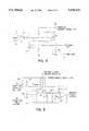
- FIGS. 4 and 5constitute a circuit diagram showing a circuit alternate to that of FIG. 3, wherein the "front end" oscillator circuit shown in FIG. 4 is essentially the same as that of FIG. 3, and the circuit shown in FIG. 5 acts as a signal conditioner.
- the device of the inventionis a capacitive sensor which is capable of non-contact sensing of a silicon wafer, a glass mask plate, or any other material which will change the capacity of two adjacent coplanar capacitor plates when brought into close proximity.
- the essential parts of the deviceare (1) an oscillator, the frequency of which is tuned by the sensor capacity, (2) a voltage follower of low output impedance, which drives (3) a triaxial cable comprising two shields and center conductor, and (4) a frequency-to-voltage converter or other appropriate output circuit.
- the sensor of the inventionincludes a ground plate 1, a sensing plate 2 and a shield plate 3.
- the ground plate 1is connected to the outer shield 4 of a triaxial cable 5 by a first lead 6.
- the sensing plate 2is connected to the center conductor 7 of the triaxial cable 5 by a second lead 8.
- the shield plate 3is connected to the inner shield 9 of the triaxial cable 5 by a third lead 10.
- the device 11 to be sensed, when present,is in close proximity to the groundplate 1 and the sensing plate 2. As shown in FIGS.
- the ground plate 1forms a support plate having an aperture and defining a plane upon which to support an article, such as a silicon wafer or a glass mask plate;
- the sensing plate 2forms a sensor plate in said aperture close to but spaced below said plane, whereby a portion of the capacitance between said sensor plate and said support plate is created by the mutual geometry of said sensor plate and said support plate and whereby said capacitance is increased when an article is placed on said support plate;
- the shield plate 3forms a driven shield placed so as to shield said sensor plate from any other major capacitance between said sensor plate and said support plate.
- the frequency of the oscillator of the inventionis determined by a suitable resistor-capacitor (RC) circuit, and the circuitry of the oscillator and the voltage follower of the invention makes use of operational amplifiers (op-amps).
- resistor and capacitor componentscan be made to tight stability, because modern operational amplifiers provide broad-band high gain and low output impedance, and because a triaxial cable allows the driving of the inner shield thereof by a voltage follower into a fixed capacitance to the outer (ground) shield of the triaxial cable, the capacitance of the sensor head can be made a majority of the total tuning capacitance, and the frequency change with an approaching device to be sensed becomes large.
- FIG. 3One embodiment of the circuitry of the invention is shown in FIG. 3, wherein bias networks, waveform shaping, and similar ancillary circuits are not shown.
- a saw-tooth wave formis generated by an inverter circuit 12 having a resistive feedback 13 and an input capacitance to ground.
- the input capacitanceis formed by the sensing plate 2, which is connected to the op-amp input (i.e. the input of the inverter circuit 12), and the shield plate 3 is connected to the inner shield 9.
- connectionare: the center conductor 7 of the triaxial cable 5 is connected to the sensing plate 2 by the second lead 8, and the outer (ground) shield 4 of the triaxial cable 5 is connected to the ground plate 1 and to the a-c ground of the op-amp.
- the inner shield 9 of the triaxial cable 5may be extended to shield the sensing plate 2 from ground.
- the inverter circuit 12 of FIG. 3having said resistive feedback 13 and said input capacitance to ground, forms an oscillator having an input connected to said sensor plate and having a frequency which is a function of said capacitance.
- the inner shield 9which cancels the cable capacitance by being driven by a voltage follower 14. While the capacitance of the cable from inner shield to center conductor may be tens of picofarads, if, because of the voltage-follower, there is no voltage difference between the two conductors, there will also be no current, and the effect will be negligible on the oscillation which is at a high impedance node. Simultaneously the capacitance of the inner shield to the outer shield will be driven by the low impedance of the voltage follower and the current required will not significantly distort the inner shield voltage waveform.
- said standard frequency-to-voltage converter 15 and said voltage meterform means for measuring said frequency.
- the circuitry, sensor, and triaxial cable shown in FIG. 3may all be within the vacuum chamber which encloses the end effector. If so, in addition to the ground lead, two conductors are required which must pass through the wall of the vacuum chamber: one is the conductor for the power delivered to the oscillator and voltage follower, and the other is the conductor for the square-wave voltage output which is delivered to the frequency-to-voltage converter.
- the number of conductors thus requiredmay be reduced to one by means of a circuit such as the signal conditioner shown in FIG. 5, which replaces the frequency-to-voltage converter 15 shown in FIG. 3.
- the rest of the circuit of FIG. 3(which may be designated a "front end" oscillator) is slightly modified as shown in FIG. 4.
- the signal conditioner therein shownincludes an input op-amp 21 the minus input whereof receives a current signal and the output whereof delivers a reconstituted square-wave voltage.
- Power input 22 from a suitable power supplyis delivered to the hot lead A of the front-end oscillator via a resistor 23.
- the power input 22is connected to ground through a resistor 24 and a zener voltage-reference diode 25 operating in the zener mode at a voltage of, e.g. 3 volts, and the plus input of the input op-amp 21 is connected to the junction of the resistor 24 and zener diode 25.
- the power for the op-amp 21is provided by the power supply input 22.
- a feedback resistor R senseis connected between the output and the minus input of the input op-amp 21.
- the ground of the signal conditioner of FIG. 5is connected to the ground of the "front end" oscillator of FIG. 4.
- the square wave voltage oscillationdrives the load resistor R L and this signal may be used directly, as hereinbefore described, as the input to a frequency-to-voltage converter such as that shown at 15 in FIG. 3.
- the current through the load resistoris provided by the power input, such that the current provided by the power supply through the signal conditioner will be, typically, 5 ma greater for a "high" half-wave of oscillation than for a "low” half-wave.
- the input circuit of the conditionerwill sense the change and the input op-amp 21 will generate a current through R sense to keep the op amp minus input at virtual ground.
- the voltage ( ⁇ I times R sense )is the reconstituted oscillation.
- the potentiometer 29allows threshold setting for switching outputs. Alternate circuits will give an analog output.
- the current through the resistor 23remains at the average current delivered to the "front end" oscillator of FIG. 4 from the power supply input 22 of the signal conditioner of FIG. 5. Any tendency for this current to change as a result of the aforementioned changes in the current through the load resistor R L will result in a tendency for the voltage at the minus input to the op-amp 21 to change. However, the latter tendency is immediately corrected by the feedback of the op-amp 21 through the resistor R sense . As a result, any change in current through the load resistor R L appears as a change in current through the feedback resistor R sense , while the current through the resistor 23 remains the average current from the power supply input 22.
- the output voltage of the op-amp 21In order to cause this change in current through the feedback resistor R sense the output voltage of the op-amp 21 must change in such a way as to reconsititute the original square wave voltage output from the op-amp 12 of FIG. 4. This voltage output is converted to a pulse by the capacitance 26, which thus acts as a differentiator.
- the capacitance 26When the square wave voltage output rises from low to high, a positive pulse travels through the diode 28 to the minus input of the op-amp 30, which acts as an integrating amplifier. The resulting negative feedback pulse charges the feedback capacitance 31.
- the square wave voltage output from op-amp 21falls from high to low, the charged capacitance 26 discharges through the diode 27.
- the charge temporarily stored in the capacitance 31is constantly bled off through the resistor 32, and the amount of this current is proportional to the frequency with which the capacitance 31 is charged.
- the voltage output of the op-amp 30is proportional to the frequency of the square-wave signal, and the op-amp acts as an integrating amplifier.
- a circuit in the signal conditionerconverts the varying current into a voltage wave replicating the original oscillation of the front end circuit.
- a further circuitconverts the frequency square wave into an analog voltage proportional to the frequency or to an on/off switch signal.
Landscapes
- Physics & Mathematics (AREA)
- General Physics & Mathematics (AREA)
- Life Sciences & Earth Sciences (AREA)
- General Life Sciences & Earth Sciences (AREA)
- Geophysics (AREA)
- Measurement Of Length, Angles, Or The Like Using Electric Or Magnetic Means (AREA)
- Measurement Of Resistance Or Impedance (AREA)
- Measurement Of Mechanical Vibrations Or Ultrasonic Waves (AREA)
Abstract
Description
Claims (8)
Priority Applications (6)
| Application Number | Priority Date | Filing Date | Title |
|---|---|---|---|
| US08/058,421US5539323A (en) | 1993-05-07 | 1993-05-07 | Sensor for articles such as wafers on end effector |
| KR1019950704979AKR960702619A (en) | 1993-05-07 | 1994-04-28 | Detectors for wafers on the end effector |
| CN94192160ACN1124060A (en) | 1993-05-07 | 1994-04-28 | Sensor for articles on an end effector |
| EP94915430AEP0697113A1 (en) | 1993-05-07 | 1994-04-28 | Sensor for articles on an end effector |
| JP52547494AJP3372254B2 (en) | 1993-05-07 | 1994-04-28 | Article sensor on end effector |
| PCT/US1994/004672WO1994027158A1 (en) | 1993-05-07 | 1994-04-28 | Sensor for articles on an end effector |
Applications Claiming Priority (1)
| Application Number | Priority Date | Filing Date | Title |
|---|---|---|---|
| US08/058,421US5539323A (en) | 1993-05-07 | 1993-05-07 | Sensor for articles such as wafers on end effector |
Publications (1)
| Publication Number | Publication Date |
|---|---|
| US5539323Atrue US5539323A (en) | 1996-07-23 |
Family
ID=22016714
Family Applications (1)
| Application Number | Title | Priority Date | Filing Date |
|---|---|---|---|
| US08/058,421Expired - LifetimeUS5539323A (en) | 1993-05-07 | 1993-05-07 | Sensor for articles such as wafers on end effector |
Country Status (6)
| Country | Link |
|---|---|
| US (1) | US5539323A (en) |
| EP (1) | EP0697113A1 (en) |
| JP (1) | JP3372254B2 (en) |
| KR (1) | KR960702619A (en) |
| CN (1) | CN1124060A (en) |
| WO (1) | WO1994027158A1 (en) |
Cited By (82)
| Publication number | Priority date | Publication date | Assignee | Title |
|---|---|---|---|---|
| US5948986A (en)* | 1997-12-26 | 1999-09-07 | Applied Materials, Inc. | Monitoring of wafer presence and position in semiconductor processing operations |
| US5980194A (en)* | 1996-07-15 | 1999-11-09 | Applied Materials, Inc. | Wafer position error detection and correction system |
| US6075375A (en)* | 1997-06-11 | 2000-06-13 | Applied Materials, Inc. | Apparatus for wafer detection |
| US6215640B1 (en) | 1998-12-10 | 2001-04-10 | Applied Materials, Inc. | Apparatus and method for actively controlling surface potential of an electrostatic chuck |
| US6257045B1 (en) | 1997-10-10 | 2001-07-10 | Applied Komatsu Technology, Inc. | Automated substrate processing systems and methods |
| US6291773B1 (en)* | 1995-02-17 | 2001-09-18 | Bently Nevada Corporation | Apparatus and method for precluding fluid wicking |
| US6385503B2 (en)* | 1997-06-17 | 2002-05-07 | U.S. Philips Corporation | Reactor for the processing of wafers, with a protection device |
| US6395977B1 (en)* | 1997-01-30 | 2002-05-28 | Matsushita Electric Industrial Co., Ltd. | Method and cable for connecting electronic equipment to another electronic equipment |
| US6411108B1 (en) | 1999-11-05 | 2002-06-25 | Sensor Technologies, Inc. | Noncontact signal analyzer |
| WO2003007345A1 (en)* | 2001-07-13 | 2003-01-23 | Tru-Si Technologies, Inc. | Article holders with sensors detecting a type of article held by the holder |
| US6545483B1 (en) | 2001-08-29 | 2003-04-08 | Sensor Technologies, Inc. | Analyzer sensor |
| US6610932B2 (en) | 1999-03-01 | 2003-08-26 | Bently Neveda, Llc | Cable and method for precluding fluid wicking |
| US20040012363A1 (en)* | 2002-03-20 | 2004-01-22 | Fsi International, Inc. | Systems and methods incorporating an end effector with a rotatable and/or pivotable body and/or an optical sensor having a light path that extends along a length of the end effector |
| US20040183499A1 (en)* | 2003-02-12 | 2004-09-23 | Fanuc Ltd. | Inverter unit grounding method and inverter unit |
| US6911873B2 (en)* | 2003-06-24 | 2005-06-28 | Stmicroelectronics, Inc. | Detection circuit and method for an oscillator |
| WO2005060653A3 (en)* | 2003-12-18 | 2005-12-01 | Du Pont | Inductive probe having a looped sensing element or a terminated transmission line sensing element and methods and system for using the same |
| EP1602892A1 (en)* | 2004-06-03 | 2005-12-07 | General Electric Company | A non-contact capacitive sensor and cable with dual layer active shield |
| US20060139035A1 (en)* | 2004-04-16 | 2006-06-29 | General Electric Company | Capacitive sensor for non-contacting gap and dielectric medium measurement |
| US20060181284A1 (en)* | 2002-07-30 | 2006-08-17 | Volker Fraedrich | Method and apparatus for the location and indication of cable splices and cable faults |
| US20060220740A1 (en)* | 2005-03-31 | 2006-10-05 | Agilent Technologies, Inc. | Apparatus for current measuring and a resistor |
| US7138813B2 (en) | 1999-06-30 | 2006-11-21 | Cascade Microtech, Inc. | Probe station thermal chuck with shielding for capacitive current |
| US7138810B2 (en) | 2002-11-08 | 2006-11-21 | Cascade Microtech, Inc. | Probe station with low noise characteristics |
| US7164279B2 (en) | 1995-04-14 | 2007-01-16 | Cascade Microtech, Inc. | System for evaluating probing networks |
| US7176705B2 (en) | 2004-06-07 | 2007-02-13 | Cascade Microtech, Inc. | Thermal optical chuck |
| US7187188B2 (en) | 2003-12-24 | 2007-03-06 | Cascade Microtech, Inc. | Chuck with integrated wafer support |
| US7190181B2 (en) | 1997-06-06 | 2007-03-13 | Cascade Microtech, Inc. | Probe station having multiple enclosures |
| US7221172B2 (en) | 2003-05-06 | 2007-05-22 | Cascade Microtech, Inc. | Switched suspended conductor and connection |
| US7221146B2 (en) | 2002-12-13 | 2007-05-22 | Cascade Microtech, Inc. | Guarded tub enclosure |
| EP1793207A1 (en)* | 2005-12-02 | 2007-06-06 | Vibro-Meter Sa | Eddy current sensor and sensor coil for the same |
| US7235986B1 (en)* | 2002-10-21 | 2007-06-26 | Victor Iannello | Capacitive position sensing system with resonant amplification |
| US7250779B2 (en) | 2002-11-25 | 2007-07-31 | Cascade Microtech, Inc. | Probe station with low inductance path |
| US7250626B2 (en) | 2003-10-22 | 2007-07-31 | Cascade Microtech, Inc. | Probe testing structure |
| US7268533B2 (en) | 2001-08-31 | 2007-09-11 | Cascade Microtech, Inc. | Optical testing device |
| US7304488B2 (en) | 2002-05-23 | 2007-12-04 | Cascade Microtech, Inc. | Shielded probe for high-frequency testing of a device under test |
| US7314997B1 (en)* | 2005-07-18 | 2008-01-01 | Yazaki North America, Inc. | High speed data communication link using triaxial cable |
| US7330041B2 (en) | 2004-06-14 | 2008-02-12 | Cascade Microtech, Inc. | Localizing a temperature of a device for testing |
| US7330023B2 (en) | 1992-06-11 | 2008-02-12 | Cascade Microtech, Inc. | Wafer probe station having a skirting component |
| US7348787B2 (en) | 1992-06-11 | 2008-03-25 | Cascade Microtech, Inc. | Wafer probe station having environment control enclosure |
| US7352168B2 (en) | 2000-09-05 | 2008-04-01 | Cascade Microtech, Inc. | Chuck for holding a device under test |
| US7355420B2 (en) | 2001-08-21 | 2008-04-08 | Cascade Microtech, Inc. | Membrane probing system |
| US7368925B2 (en) | 2002-01-25 | 2008-05-06 | Cascade Microtech, Inc. | Probe station with two platens |
| US7368927B2 (en) | 2004-07-07 | 2008-05-06 | Cascade Microtech, Inc. | Probe head having a membrane suspended probe |
| US7403028B2 (en) | 2006-06-12 | 2008-07-22 | Cascade Microtech, Inc. | Test structure and probe for differential signals |
| US7403025B2 (en) | 2000-02-25 | 2008-07-22 | Cascade Microtech, Inc. | Membrane probing system |
| US7417446B2 (en) | 2002-11-13 | 2008-08-26 | Cascade Microtech, Inc. | Probe for combined signals |
| US7420381B2 (en) | 2004-09-13 | 2008-09-02 | Cascade Microtech, Inc. | Double sided probing structures |
| US7443186B2 (en) | 2006-06-12 | 2008-10-28 | Cascade Microtech, Inc. | On-wafer test structures for differential signals |
| US7449899B2 (en) | 2005-06-08 | 2008-11-11 | Cascade Microtech, Inc. | Probe for high frequency signals |
| US7456646B2 (en) | 2000-12-04 | 2008-11-25 | Cascade Microtech, Inc. | Wafer probe |
| US20080297159A1 (en)* | 2004-09-10 | 2008-12-04 | Mehrdad Mehdizadeh | Sensing Apparatus for Detecting an Interface Between First and Second Strata of Materials |
| US7492172B2 (en) | 2003-05-23 | 2009-02-17 | Cascade Microtech, Inc. | Chuck for holding a device under test |
| US7498829B2 (en) | 2003-05-23 | 2009-03-03 | Cascade Microtech, Inc. | Shielded probe for testing a device under test |
| US7504842B2 (en) | 1997-05-28 | 2009-03-17 | Cascade Microtech, Inc. | Probe holder for testing of a test device |
| US7533462B2 (en) | 1999-06-04 | 2009-05-19 | Cascade Microtech, Inc. | Method of constructing a membrane probe |
| US7535247B2 (en) | 2005-01-31 | 2009-05-19 | Cascade Microtech, Inc. | Interface for testing semiconductors |
| US7538561B2 (en) | 2004-09-10 | 2009-05-26 | E. I. Du Pont De Nemours And Company | Method for detecting an interface between first and second strata of materials |
| US7541821B2 (en) | 1996-08-08 | 2009-06-02 | Cascade Microtech, Inc. | Membrane probing system with local contact scrub |
| US7554322B2 (en) | 2000-09-05 | 2009-06-30 | Cascade Microtech, Inc. | Probe station |
| US7568946B1 (en)* | 2007-01-16 | 2009-08-04 | Keithley Instruments, Inc. | Triaxial cable with a resistive inner shield |
| US20090261678A1 (en)* | 2008-04-17 | 2009-10-22 | Sortore Christopher K | High-Speed Permanent Magnet Motor and Generator with Low-Loss Metal Rotor |
| US7609077B2 (en) | 2006-06-09 | 2009-10-27 | Cascade Microtech, Inc. | Differential signal probe with integral balun |
| US7619419B2 (en) | 2005-06-13 | 2009-11-17 | Cascade Microtech, Inc. | Wideband active-passive differential signal probe |
| US7656172B2 (en) | 2005-01-31 | 2010-02-02 | Cascade Microtech, Inc. | System for testing semiconductors |
| US7681312B2 (en) | 1998-07-14 | 2010-03-23 | Cascade Microtech, Inc. | Membrane probing system |
| US7723999B2 (en) | 2006-06-12 | 2010-05-25 | Cascade Microtech, Inc. | Calibration structures for differential signal probing |
| US7759953B2 (en) | 2003-12-24 | 2010-07-20 | Cascade Microtech, Inc. | Active wafer probe |
| US7764072B2 (en) | 2006-06-12 | 2010-07-27 | Cascade Microtech, Inc. | Differential signal probing system |
| US20110012618A1 (en)* | 2009-07-15 | 2011-01-20 | Maxim Integrated Products, Inc. | Method and apparatus for sensing capacitance value and converting it into digital format |
| US7876114B2 (en) | 2007-08-08 | 2011-01-25 | Cascade Microtech, Inc. | Differential waveguide probe |
| US7888957B2 (en) | 2008-10-06 | 2011-02-15 | Cascade Microtech, Inc. | Probing apparatus with impedance optimized interface |
| WO2011080308A1 (en)* | 2009-12-31 | 2011-07-07 | Mapper Lithography Ip B.V. | Capacitive sensing system |
| US20110267088A1 (en)* | 2008-08-07 | 2011-11-03 | Rosenberger Hochfrequenztechnik Gmbh & Co. Kg | Contactless loop probe |
| US20120224945A1 (en)* | 2011-03-02 | 2012-09-06 | Tokyo Electron Limited | Substrate holder positioning method and substrate processing system |
| US8319503B2 (en) | 2008-11-24 | 2012-11-27 | Cascade Microtech, Inc. | Test apparatus for measuring a characteristic of a device under test |
| US8330311B2 (en) | 2008-04-18 | 2012-12-11 | Dresser-Rand Company | Magnetic thrust bearing with integrated electronics |
| US8410806B2 (en) | 2008-11-21 | 2013-04-02 | Cascade Microtech, Inc. | Replaceable coupon for a probing apparatus |
| US20140085199A1 (en)* | 2008-07-28 | 2014-03-27 | Samsung Electronics Co., Ltd. | Mobile terminal having touch screen and method for displaying cursor thereof |
| US8987959B2 (en) | 2010-06-23 | 2015-03-24 | Dresser-Rand Company | Split magnetic thrust bearing |
| US9583991B2 (en) | 2009-06-24 | 2017-02-28 | Synchrony, Inc. | Systems, devices, and/or methods for managing magnetic bearings |
| CN108736434A (en)* | 2018-08-10 | 2018-11-02 | 中航建设集团成套装备股份有限公司 | A kind of cable T-type connect-disconnect plug |
| US10950369B1 (en)* | 2020-07-20 | 2021-03-16 | Dell Products L.P. | Inverted cable design for high-speed, low loss signal transmission |
| US20250164659A1 (en)* | 2023-11-17 | 2025-05-22 | Pixart Imaging Inc. | Capacitive sensing system using active shielding and operating method thereof |
Families Citing this family (9)
| Publication number | Priority date | Publication date | Assignee | Title |
|---|---|---|---|---|
| JP2002062105A (en)* | 2000-08-23 | 2002-02-28 | Sunx Ltd | Head-separated-type sensor, capacitance-type sensor, and wafer detecting device |
| JP4531469B2 (en)* | 2004-07-15 | 2010-08-25 | 株式会社フジクラ | Capacitive proximity sensor |
| EP1875156A2 (en)* | 2005-04-27 | 2008-01-09 | Roho, Inc. | Proximity sensor |
| US9644995B2 (en)* | 2011-06-30 | 2017-05-09 | Mapper Lithography Ip B.V. | Current measurement system |
| US9983228B2 (en)* | 2014-09-24 | 2018-05-29 | Keithley Instruments, Llc | Triaxial DC-AC connection system |
| JP2018137189A (en)* | 2017-02-24 | 2018-08-30 | 株式会社シンテックホズミ | Proximity sensor |
| US10890990B2 (en)* | 2017-09-25 | 2021-01-12 | Google Llc | Rotation input device for a capacitive sense cord |
| CN112924771A (en)* | 2019-12-06 | 2021-06-08 | 基思利仪器有限责任公司 | Triaxial power and control system and method |
| WO2025047692A1 (en)* | 2023-08-28 | 2025-03-06 | アルプスアルパイン株式会社 | Capacitive sensor, sensor sheet, sensor unit, detection circuit, and capacitance detection device |
Citations (16)
| Publication number | Priority date | Publication date | Assignee | Title |
|---|---|---|---|---|
| US3626287A (en)* | 1969-02-10 | 1971-12-07 | C G I Corp | System for responding to changes in capacitance of a sensing capacitor |
| US3870948A (en)* | 1972-09-05 | 1975-03-11 | Acme Cleveland Corp | Proximity circuit with active device feedback |
| US3883826A (en)* | 1971-07-15 | 1975-05-13 | Ici Ltd | Adjustable frequency oscillator with regenerative feedback and a coupling unit including a differential amplifier for adjusting the feedback |
| US4067225A (en)* | 1977-03-21 | 1978-01-10 | Mechanical Technology Incorporated | Capacitance type non-contact displacement and vibration measuring device and method of maintaining calibration |
| US4176555A (en)* | 1978-08-07 | 1979-12-04 | Mechanical Technology Incorporated | Signal amplifier system for controlled carrier signal measuring sensor/transducer of the variable impedance type |
| US4347741A (en)* | 1980-07-17 | 1982-09-07 | Endress & Hauser, Inc. | Control system for a capacitive level sensor |
| US4666366A (en)* | 1983-02-14 | 1987-05-19 | Canon Kabushiki Kaisha | Articulated arm transfer device |
| US4743837A (en)* | 1985-12-13 | 1988-05-10 | Flowtec Ag | Circuit for measuring capacitance by charging and discharging capacitor under test and its shield |
| US4763063A (en)* | 1985-07-26 | 1988-08-09 | Allied-Signal Inc. | Compact digital pressure sensor circuitry |
| US4794320A (en)* | 1987-08-10 | 1988-12-27 | Moore Products Co. | Multi-frequency capacitance sensor |
| US4909701A (en)* | 1983-02-14 | 1990-03-20 | Brooks Automation Inc. | Articulated arm transfer device |
| US4918376A (en)* | 1989-03-07 | 1990-04-17 | Ade Corporation | A.C. capacitive gauging system |
| US5021740A (en)* | 1989-03-07 | 1991-06-04 | The Boeing Company | Method and apparatus for measuring the distance between a body and a capacitance probe |
| US5045797A (en)* | 1986-10-14 | 1991-09-03 | Drexelbrook Controls, Inc. | Continuous condition sensing system determining liquid level by admittance measurement |
| US5148126A (en)* | 1991-12-13 | 1992-09-15 | Sentech Corporation | Capacitance sensor circuit and method for measuring capacitance and small changes in capacitance |
| US5363051A (en)* | 1992-11-23 | 1994-11-08 | The United States Of America As Represented By The Administrator Of The National Aeronautics And Space Administration | Steering capaciflector sensor |
Family Cites Families (1)
| Publication number | Priority date | Publication date | Assignee | Title |
|---|---|---|---|---|
| US5166679A (en)* | 1991-06-06 | 1992-11-24 | The United States Of America As Represented By The Administrator Of The National Aeronautics & Space Administration | Driven shielding capacitive proximity sensor |
- 1993
- 1993-05-07USUS08/058,421patent/US5539323A/ennot_activeExpired - Lifetime
- 1994
- 1994-04-28WOPCT/US1994/004672patent/WO1994027158A1/ennot_activeApplication Discontinuation
- 1994-04-28EPEP94915430Apatent/EP0697113A1/ennot_activeWithdrawn
- 1994-04-28KRKR1019950704979Apatent/KR960702619A/ennot_activeWithdrawn
- 1994-04-28CNCN94192160Apatent/CN1124060A/enactivePending
- 1994-04-28JPJP52547494Apatent/JP3372254B2/ennot_activeExpired - Fee Related
Patent Citations (16)
| Publication number | Priority date | Publication date | Assignee | Title |
|---|---|---|---|---|
| US3626287A (en)* | 1969-02-10 | 1971-12-07 | C G I Corp | System for responding to changes in capacitance of a sensing capacitor |
| US3883826A (en)* | 1971-07-15 | 1975-05-13 | Ici Ltd | Adjustable frequency oscillator with regenerative feedback and a coupling unit including a differential amplifier for adjusting the feedback |
| US3870948A (en)* | 1972-09-05 | 1975-03-11 | Acme Cleveland Corp | Proximity circuit with active device feedback |
| US4067225A (en)* | 1977-03-21 | 1978-01-10 | Mechanical Technology Incorporated | Capacitance type non-contact displacement and vibration measuring device and method of maintaining calibration |
| US4176555A (en)* | 1978-08-07 | 1979-12-04 | Mechanical Technology Incorporated | Signal amplifier system for controlled carrier signal measuring sensor/transducer of the variable impedance type |
| US4347741A (en)* | 1980-07-17 | 1982-09-07 | Endress & Hauser, Inc. | Control system for a capacitive level sensor |
| US4666366A (en)* | 1983-02-14 | 1987-05-19 | Canon Kabushiki Kaisha | Articulated arm transfer device |
| US4909701A (en)* | 1983-02-14 | 1990-03-20 | Brooks Automation Inc. | Articulated arm transfer device |
| US4763063A (en)* | 1985-07-26 | 1988-08-09 | Allied-Signal Inc. | Compact digital pressure sensor circuitry |
| US4743837A (en)* | 1985-12-13 | 1988-05-10 | Flowtec Ag | Circuit for measuring capacitance by charging and discharging capacitor under test and its shield |
| US5045797A (en)* | 1986-10-14 | 1991-09-03 | Drexelbrook Controls, Inc. | Continuous condition sensing system determining liquid level by admittance measurement |
| US4794320A (en)* | 1987-08-10 | 1988-12-27 | Moore Products Co. | Multi-frequency capacitance sensor |
| US4918376A (en)* | 1989-03-07 | 1990-04-17 | Ade Corporation | A.C. capacitive gauging system |
| US5021740A (en)* | 1989-03-07 | 1991-06-04 | The Boeing Company | Method and apparatus for measuring the distance between a body and a capacitance probe |
| US5148126A (en)* | 1991-12-13 | 1992-09-15 | Sentech Corporation | Capacitance sensor circuit and method for measuring capacitance and small changes in capacitance |
| US5363051A (en)* | 1992-11-23 | 1994-11-08 | The United States Of America As Represented By The Administrator Of The National Aeronautics And Space Administration | Steering capaciflector sensor |
Cited By (151)
| Publication number | Priority date | Publication date | Assignee | Title |
|---|---|---|---|---|
| US7348787B2 (en) | 1992-06-11 | 2008-03-25 | Cascade Microtech, Inc. | Wafer probe station having environment control enclosure |
| US7595632B2 (en) | 1992-06-11 | 2009-09-29 | Cascade Microtech, Inc. | Wafer probe station having environment control enclosure |
| US7589518B2 (en) | 1992-06-11 | 2009-09-15 | Cascade Microtech, Inc. | Wafer probe station having a skirting component |
| US7330023B2 (en) | 1992-06-11 | 2008-02-12 | Cascade Microtech, Inc. | Wafer probe station having a skirting component |
| US7492147B2 (en) | 1992-06-11 | 2009-02-17 | Cascade Microtech, Inc. | Wafer probe station having a skirting component |
| US6291773B1 (en)* | 1995-02-17 | 2001-09-18 | Bently Nevada Corporation | Apparatus and method for precluding fluid wicking |
| US7164279B2 (en) | 1995-04-14 | 2007-01-16 | Cascade Microtech, Inc. | System for evaluating probing networks |
| US7321233B2 (en) | 1995-04-14 | 2008-01-22 | Cascade Microtech, Inc. | System for evaluating probing networks |
| US5980194A (en)* | 1996-07-15 | 1999-11-09 | Applied Materials, Inc. | Wafer position error detection and correction system |
| US7541821B2 (en) | 1996-08-08 | 2009-06-02 | Cascade Microtech, Inc. | Membrane probing system with local contact scrub |
| US7893704B2 (en) | 1996-08-08 | 2011-02-22 | Cascade Microtech, Inc. | Membrane probing structure with laterally scrubbing contacts |
| US6395977B1 (en)* | 1997-01-30 | 2002-05-28 | Matsushita Electric Industrial Co., Ltd. | Method and cable for connecting electronic equipment to another electronic equipment |
| US6686538B2 (en) | 1997-01-30 | 2004-02-03 | Matsushita Electric Industrial Co., Ltd. | Method for connecting electronic devices and connecting cable |
| US7504842B2 (en) | 1997-05-28 | 2009-03-17 | Cascade Microtech, Inc. | Probe holder for testing of a test device |
| US7436170B2 (en) | 1997-06-06 | 2008-10-14 | Cascade Microtech, Inc. | Probe station having multiple enclosures |
| US7626379B2 (en) | 1997-06-06 | 2009-12-01 | Cascade Microtech, Inc. | Probe station having multiple enclosures |
| US7190181B2 (en) | 1997-06-06 | 2007-03-13 | Cascade Microtech, Inc. | Probe station having multiple enclosures |
| US6377060B1 (en) | 1997-06-11 | 2002-04-23 | Applied Materials, Inc. | Method and apparatus for wafer detection |
| US6075375A (en)* | 1997-06-11 | 2000-06-13 | Applied Materials, Inc. | Apparatus for wafer detection |
| US6385503B2 (en)* | 1997-06-17 | 2002-05-07 | U.S. Philips Corporation | Reactor for the processing of wafers, with a protection device |
| US6257045B1 (en) | 1997-10-10 | 2001-07-10 | Applied Komatsu Technology, Inc. | Automated substrate processing systems and methods |
| US5948986A (en)* | 1997-12-26 | 1999-09-07 | Applied Materials, Inc. | Monitoring of wafer presence and position in semiconductor processing operations |
| US7681312B2 (en) | 1998-07-14 | 2010-03-23 | Cascade Microtech, Inc. | Membrane probing system |
| US7761986B2 (en) | 1998-07-14 | 2010-07-27 | Cascade Microtech, Inc. | Membrane probing method using improved contact |
| US8451017B2 (en) | 1998-07-14 | 2013-05-28 | Cascade Microtech, Inc. | Membrane probing method using improved contact |
| US6215640B1 (en) | 1998-12-10 | 2001-04-10 | Applied Materials, Inc. | Apparatus and method for actively controlling surface potential of an electrostatic chuck |
| US6610932B2 (en) | 1999-03-01 | 2003-08-26 | Bently Neveda, Llc | Cable and method for precluding fluid wicking |
| US7533462B2 (en) | 1999-06-04 | 2009-05-19 | Cascade Microtech, Inc. | Method of constructing a membrane probe |
| US7292057B2 (en) | 1999-06-30 | 2007-11-06 | Cascade Microtech, Inc. | Probe station thermal chuck with shielding for capacitive current |
| US7616017B2 (en) | 1999-06-30 | 2009-11-10 | Cascade Microtech, Inc. | Probe station thermal chuck with shielding for capacitive current |
| US7138813B2 (en) | 1999-06-30 | 2006-11-21 | Cascade Microtech, Inc. | Probe station thermal chuck with shielding for capacitive current |
| US6411108B1 (en) | 1999-11-05 | 2002-06-25 | Sensor Technologies, Inc. | Noncontact signal analyzer |
| US7403025B2 (en) | 2000-02-25 | 2008-07-22 | Cascade Microtech, Inc. | Membrane probing system |
| US7352168B2 (en) | 2000-09-05 | 2008-04-01 | Cascade Microtech, Inc. | Chuck for holding a device under test |
| US7688062B2 (en) | 2000-09-05 | 2010-03-30 | Cascade Microtech, Inc. | Probe station |
| US7514915B2 (en) | 2000-09-05 | 2009-04-07 | Cascade Microtech, Inc. | Chuck for holding a device under test |
| US7501810B2 (en) | 2000-09-05 | 2009-03-10 | Cascade Microtech, Inc. | Chuck for holding a device under test |
| US7554322B2 (en) | 2000-09-05 | 2009-06-30 | Cascade Microtech, Inc. | Probe station |
| US7518358B2 (en) | 2000-09-05 | 2009-04-14 | Cascade Microtech, Inc. | Chuck for holding a device under test |
| US7969173B2 (en) | 2000-09-05 | 2011-06-28 | Cascade Microtech, Inc. | Chuck for holding a device under test |
| US7423419B2 (en) | 2000-09-05 | 2008-09-09 | Cascade Microtech, Inc. | Chuck for holding a device under test |
| US7495461B2 (en) | 2000-12-04 | 2009-02-24 | Cascade Microtech, Inc. | Wafer probe |
| US7761983B2 (en) | 2000-12-04 | 2010-07-27 | Cascade Microtech, Inc. | Method of assembling a wafer probe |
| US7688097B2 (en) | 2000-12-04 | 2010-03-30 | Cascade Microtech, Inc. | Wafer probe |
| US7456646B2 (en) | 2000-12-04 | 2008-11-25 | Cascade Microtech, Inc. | Wafer probe |
| WO2003007345A1 (en)* | 2001-07-13 | 2003-01-23 | Tru-Si Technologies, Inc. | Article holders with sensors detecting a type of article held by the holder |
| US6615113B2 (en) | 2001-07-13 | 2003-09-02 | Tru-Si Technologies, Inc. | Articles holders with sensors detecting a type of article held by the holder |
| US7027894B2 (en) | 2001-07-13 | 2006-04-11 | Tru-Si Technologies, Inc. | Article holders with sensors detecting a type of article held by the holder |
| US6665583B2 (en) | 2001-07-13 | 2003-12-16 | Tru-Si Technologies, Inc. | Article holders with sensors detecting a type of article held by the holder |
| US20040049318A1 (en)* | 2001-07-13 | 2004-03-11 | Kretz Frank E. | Article holders with sensors detecting a type of article held by the holder |
| US7492175B2 (en) | 2001-08-21 | 2009-02-17 | Cascade Microtech, Inc. | Membrane probing system |
| US7355420B2 (en) | 2001-08-21 | 2008-04-08 | Cascade Microtech, Inc. | Membrane probing system |
| US6545483B1 (en) | 2001-08-29 | 2003-04-08 | Sensor Technologies, Inc. | Analyzer sensor |
| US7268533B2 (en) | 2001-08-31 | 2007-09-11 | Cascade Microtech, Inc. | Optical testing device |
| US7368925B2 (en) | 2002-01-25 | 2008-05-06 | Cascade Microtech, Inc. | Probe station with two platens |
| US20040012363A1 (en)* | 2002-03-20 | 2004-01-22 | Fsi International, Inc. | Systems and methods incorporating an end effector with a rotatable and/or pivotable body and/or an optical sensor having a light path that extends along a length of the end effector |
| US6822413B2 (en) | 2002-03-20 | 2004-11-23 | Fsi International, Inc. | Systems and methods incorporating an end effector with a rotatable and/or pivotable body and/or an optical sensor having a light path that extends along a length of the end effector |
| US7436194B2 (en) | 2002-05-23 | 2008-10-14 | Cascade Microtech, Inc. | Shielded probe with low contact resistance for testing a device under test |
| US7518387B2 (en) | 2002-05-23 | 2009-04-14 | Cascade Microtech, Inc. | Shielded probe for testing a device under test |
| US7489149B2 (en) | 2002-05-23 | 2009-02-10 | Cascade Microtech, Inc. | Shielded probe for testing a device under test |
| US7304488B2 (en) | 2002-05-23 | 2007-12-04 | Cascade Microtech, Inc. | Shielded probe for high-frequency testing of a device under test |
| US7482823B2 (en) | 2002-05-23 | 2009-01-27 | Cascade Microtech, Inc. | Shielded probe for testing a device under test |
| US20060181284A1 (en)* | 2002-07-30 | 2006-08-17 | Volker Fraedrich | Method and apparatus for the location and indication of cable splices and cable faults |
| US7443172B2 (en)* | 2002-07-30 | 2008-10-28 | Hagenuk Kmt Kabelmesstechnik Gmbh | Method and apparatus for the location and indication of cable splices and cable faults |
| US7235986B1 (en)* | 2002-10-21 | 2007-06-26 | Victor Iannello | Capacitive position sensing system with resonant amplification |
| US7138810B2 (en) | 2002-11-08 | 2006-11-21 | Cascade Microtech, Inc. | Probe station with low noise characteristics |
| US7295025B2 (en) | 2002-11-08 | 2007-11-13 | Cascade Microtech, Inc. | Probe station with low noise characteristics |
| US7550984B2 (en) | 2002-11-08 | 2009-06-23 | Cascade Microtech, Inc. | Probe station with low noise characteristics |
| US7453276B2 (en) | 2002-11-13 | 2008-11-18 | Cascade Microtech, Inc. | Probe for combined signals |
| US7417446B2 (en) | 2002-11-13 | 2008-08-26 | Cascade Microtech, Inc. | Probe for combined signals |
| US7250779B2 (en) | 2002-11-25 | 2007-07-31 | Cascade Microtech, Inc. | Probe station with low inductance path |
| US7498828B2 (en) | 2002-11-25 | 2009-03-03 | Cascade Microtech, Inc. | Probe station with low inductance path |
| US7221146B2 (en) | 2002-12-13 | 2007-05-22 | Cascade Microtech, Inc. | Guarded tub enclosure |
| US7639003B2 (en) | 2002-12-13 | 2009-12-29 | Cascade Microtech, Inc. | Guarded tub enclosure |
| US20040183499A1 (en)* | 2003-02-12 | 2004-09-23 | Fanuc Ltd. | Inverter unit grounding method and inverter unit |
| US7173395B2 (en)* | 2003-02-12 | 2007-02-06 | Fanuc Ltd | Inverter unit grounding method and inverter unit |
| US7221172B2 (en) | 2003-05-06 | 2007-05-22 | Cascade Microtech, Inc. | Switched suspended conductor and connection |
| US7468609B2 (en) | 2003-05-06 | 2008-12-23 | Cascade Microtech, Inc. | Switched suspended conductor and connection |
| US7492172B2 (en) | 2003-05-23 | 2009-02-17 | Cascade Microtech, Inc. | Chuck for holding a device under test |
| US7498829B2 (en) | 2003-05-23 | 2009-03-03 | Cascade Microtech, Inc. | Shielded probe for testing a device under test |
| US7898273B2 (en) | 2003-05-23 | 2011-03-01 | Cascade Microtech, Inc. | Probe for testing a device under test |
| US7501842B2 (en) | 2003-05-23 | 2009-03-10 | Cascade Microtech, Inc. | Shielded probe for testing a device under test |
| US7876115B2 (en) | 2003-05-23 | 2011-01-25 | Cascade Microtech, Inc. | Chuck for holding a device under test |
| US6911873B2 (en)* | 2003-06-24 | 2005-06-28 | Stmicroelectronics, Inc. | Detection circuit and method for an oscillator |
| US7250626B2 (en) | 2003-10-22 | 2007-07-31 | Cascade Microtech, Inc. | Probe testing structure |
| US8069491B2 (en) | 2003-10-22 | 2011-11-29 | Cascade Microtech, Inc. | Probe testing structure |
| WO2005060653A3 (en)* | 2003-12-18 | 2005-12-01 | Du Pont | Inductive probe having a looped sensing element or a terminated transmission line sensing element and methods and system for using the same |
| US7759953B2 (en) | 2003-12-24 | 2010-07-20 | Cascade Microtech, Inc. | Active wafer probe |
| US7362115B2 (en) | 2003-12-24 | 2008-04-22 | Cascade Microtech, Inc. | Chuck with integrated wafer support |
| US7187188B2 (en) | 2003-12-24 | 2007-03-06 | Cascade Microtech, Inc. | Chuck with integrated wafer support |
| US7688091B2 (en) | 2003-12-24 | 2010-03-30 | Cascade Microtech, Inc. | Chuck with integrated wafer support |
| US7084643B2 (en)* | 2004-04-16 | 2006-08-01 | General Electric Company | Capacitive sensor for non-contacting gap and dielectric medium measurement |
| CN100460804C (en)* | 2004-04-16 | 2009-02-11 | 通用电气公司 | A capacitive sensor and method for non-contacting gap and dielectric medium measurement |
| US20060139035A1 (en)* | 2004-04-16 | 2006-06-29 | General Electric Company | Capacitive sensor for non-contacting gap and dielectric medium measurement |
| EP1602892A1 (en)* | 2004-06-03 | 2005-12-07 | General Electric Company | A non-contact capacitive sensor and cable with dual layer active shield |
| US20050270041A1 (en)* | 2004-06-03 | 2005-12-08 | General Electric Company | Non-contact capacitive sensor and cable with dual layer active shield |
| US6989679B2 (en)* | 2004-06-03 | 2006-01-24 | General Electric Company | Non-contact capacitive sensor and cable with dual layer active shield |
| US7504823B2 (en) | 2004-06-07 | 2009-03-17 | Cascade Microtech, Inc. | Thermal optical chuck |
| US7176705B2 (en) | 2004-06-07 | 2007-02-13 | Cascade Microtech, Inc. | Thermal optical chuck |
| US7330041B2 (en) | 2004-06-14 | 2008-02-12 | Cascade Microtech, Inc. | Localizing a temperature of a device for testing |
| US7368927B2 (en) | 2004-07-07 | 2008-05-06 | Cascade Microtech, Inc. | Probe head having a membrane suspended probe |
| US7514944B2 (en) | 2004-07-07 | 2009-04-07 | Cascade Microtech, Inc. | Probe head having a membrane suspended probe |
| US20080297159A1 (en)* | 2004-09-10 | 2008-12-04 | Mehrdad Mehdizadeh | Sensing Apparatus for Detecting an Interface Between First and Second Strata of Materials |
| US7538561B2 (en) | 2004-09-10 | 2009-05-26 | E. I. Du Pont De Nemours And Company | Method for detecting an interface between first and second strata of materials |
| US7420381B2 (en) | 2004-09-13 | 2008-09-02 | Cascade Microtech, Inc. | Double sided probing structures |
| US8013623B2 (en) | 2004-09-13 | 2011-09-06 | Cascade Microtech, Inc. | Double sided probing structures |
| US7898281B2 (en) | 2005-01-31 | 2011-03-01 | Cascade Mircotech, Inc. | Interface for testing semiconductors |
| US7940069B2 (en) | 2005-01-31 | 2011-05-10 | Cascade Microtech, Inc. | System for testing semiconductors |
| US7656172B2 (en) | 2005-01-31 | 2010-02-02 | Cascade Microtech, Inc. | System for testing semiconductors |
| US7535247B2 (en) | 2005-01-31 | 2009-05-19 | Cascade Microtech, Inc. | Interface for testing semiconductors |
| US20060220740A1 (en)* | 2005-03-31 | 2006-10-05 | Agilent Technologies, Inc. | Apparatus for current measuring and a resistor |
| US7449899B2 (en) | 2005-06-08 | 2008-11-11 | Cascade Microtech, Inc. | Probe for high frequency signals |
| US7619419B2 (en) | 2005-06-13 | 2009-11-17 | Cascade Microtech, Inc. | Wideband active-passive differential signal probe |
| US7314997B1 (en)* | 2005-07-18 | 2008-01-01 | Yazaki North America, Inc. | High speed data communication link using triaxial cable |
| US7336069B2 (en) | 2005-12-02 | 2008-02-26 | Vibro-Meter Sa | Eddy current sensor and sensor coil for the same |
| US20070229065A1 (en)* | 2005-12-02 | 2007-10-04 | Jacques Perriard | Eddy current sensor and sensor coil for the same |
| EP1793207A1 (en)* | 2005-12-02 | 2007-06-06 | Vibro-Meter Sa | Eddy current sensor and sensor coil for the same |
| US7609077B2 (en) | 2006-06-09 | 2009-10-27 | Cascade Microtech, Inc. | Differential signal probe with integral balun |
| US7723999B2 (en) | 2006-06-12 | 2010-05-25 | Cascade Microtech, Inc. | Calibration structures for differential signal probing |
| US7750652B2 (en) | 2006-06-12 | 2010-07-06 | Cascade Microtech, Inc. | Test structure and probe for differential signals |
| US7443186B2 (en) | 2006-06-12 | 2008-10-28 | Cascade Microtech, Inc. | On-wafer test structures for differential signals |
| US7403028B2 (en) | 2006-06-12 | 2008-07-22 | Cascade Microtech, Inc. | Test structure and probe for differential signals |
| US7764072B2 (en) | 2006-06-12 | 2010-07-27 | Cascade Microtech, Inc. | Differential signal probing system |
| US7568946B1 (en)* | 2007-01-16 | 2009-08-04 | Keithley Instruments, Inc. | Triaxial cable with a resistive inner shield |
| US7876114B2 (en) | 2007-08-08 | 2011-01-25 | Cascade Microtech, Inc. | Differential waveguide probe |
| US20090261678A1 (en)* | 2008-04-17 | 2009-10-22 | Sortore Christopher K | High-Speed Permanent Magnet Motor and Generator with Low-Loss Metal Rotor |
| US8698367B2 (en) | 2008-04-17 | 2014-04-15 | Synchrony, Inc. | High-speed permanent magnet motor and generator with low-loss metal rotor |
| US8330311B2 (en) | 2008-04-18 | 2012-12-11 | Dresser-Rand Company | Magnetic thrust bearing with integrated electronics |
| US20140085199A1 (en)* | 2008-07-28 | 2014-03-27 | Samsung Electronics Co., Ltd. | Mobile terminal having touch screen and method for displaying cursor thereof |
| US20110267088A1 (en)* | 2008-08-07 | 2011-11-03 | Rosenberger Hochfrequenztechnik Gmbh & Co. Kg | Contactless loop probe |
| US8963570B2 (en)* | 2008-08-07 | 2015-02-24 | Rosenberger Hochfrequenztechnik Gmbh & Co. Kg | Contactless loop probe |
| US7888957B2 (en) | 2008-10-06 | 2011-02-15 | Cascade Microtech, Inc. | Probing apparatus with impedance optimized interface |
| US9429638B2 (en) | 2008-11-21 | 2016-08-30 | Cascade Microtech, Inc. | Method of replacing an existing contact of a wafer probing assembly |
| US8410806B2 (en) | 2008-11-21 | 2013-04-02 | Cascade Microtech, Inc. | Replaceable coupon for a probing apparatus |
| US10267848B2 (en) | 2008-11-21 | 2019-04-23 | Formfactor Beaverton, Inc. | Method of electrically contacting a bond pad of a device under test with a probe |
| US8319503B2 (en) | 2008-11-24 | 2012-11-27 | Cascade Microtech, Inc. | Test apparatus for measuring a characteristic of a device under test |
| US9583991B2 (en) | 2009-06-24 | 2017-02-28 | Synchrony, Inc. | Systems, devices, and/or methods for managing magnetic bearings |
| US9151640B2 (en) | 2009-07-15 | 2015-10-06 | Maxim Integrated Products, Inc. | Method and apparatus for sensing capacitance value and converting it into digital format |
| US20110012618A1 (en)* | 2009-07-15 | 2011-01-20 | Maxim Integrated Products, Inc. | Method and apparatus for sensing capacitance value and converting it into digital format |
| US8188754B2 (en)* | 2009-07-15 | 2012-05-29 | Maxim Integrated Products, Inc. | Method and apparatus for sensing capacitance value and converting it into digital format |
| US9459298B2 (en) | 2009-07-15 | 2016-10-04 | Maxim Integrated Products, Inc. | Method and apparatus for sensing capacitance value and converting it into digital format |
| WO2011080308A1 (en)* | 2009-12-31 | 2011-07-07 | Mapper Lithography Ip B.V. | Capacitive sensing system |
| US20110193574A1 (en)* | 2009-12-31 | 2011-08-11 | Mapper Lithography Ip B.V. | Capacitive sensing system |
| US8570055B2 (en) | 2009-12-31 | 2013-10-29 | Mapper Lithography Ip B.V. | Capacitive sensing system |
| US8987959B2 (en) | 2010-06-23 | 2015-03-24 | Dresser-Rand Company | Split magnetic thrust bearing |
| US9299599B2 (en) | 2011-03-02 | 2016-03-29 | Tokyo Electron Limited | Thermal processing apparatus for thermal processing substrate and positioning method of positioning substrate transfer position |
| US20120224945A1 (en)* | 2011-03-02 | 2012-09-06 | Tokyo Electron Limited | Substrate holder positioning method and substrate processing system |
| US8755935B2 (en)* | 2011-03-02 | 2014-06-17 | Tokyo Electron Limited | Substrate holder positioning method and substrate processing system |
| CN108736434A (en)* | 2018-08-10 | 2018-11-02 | 中航建设集团成套装备股份有限公司 | A kind of cable T-type connect-disconnect plug |
| US10950369B1 (en)* | 2020-07-20 | 2021-03-16 | Dell Products L.P. | Inverted cable design for high-speed, low loss signal transmission |
| US20250164659A1 (en)* | 2023-11-17 | 2025-05-22 | Pixart Imaging Inc. | Capacitive sensing system using active shielding and operating method thereof |
Also Published As
| Publication number | Publication date |
|---|---|
| KR960702619A (en) | 1996-04-27 |
| EP0697113A1 (en) | 1996-02-21 |
| WO1994027158A1 (en) | 1994-11-24 |
| CN1124060A (en) | 1996-06-05 |
| JPH08510093A (en) | 1996-10-22 |
| JP3372254B2 (en) | 2003-01-27 |
Similar Documents
| Publication | Publication Date | Title |
|---|---|---|
| US5539323A (en) | Sensor for articles such as wafers on end effector | |
| US5442347A (en) | Double-driven shield capacitive type proximity sensor | |
| US7161360B2 (en) | Electrostatic capacitance sensor, electrostatic capacitance sensor component, object mounting body and object mounting apparatus | |
| RU96107790A (en) | SCREENED CAPACITY SENSOR | |
| US4656871A (en) | Capacitor sensor and method | |
| US4191195A (en) | Coupling circuit with driven guard | |
| EP0398728A3 (en) | Ceramic resonance type electrostatic sensor apparatus | |
| CA1054695A (en) | Article presence sensor | |
| JPH0545373A (en) | Acceleration sensor | |
| EP0168489A1 (en) | Capacitive transducer and method | |
| JP4198306B2 (en) | Capacitive sensor, semiconductor manufacturing apparatus, and liquid crystal display element manufacturing apparatus | |
| US4176555A (en) | Signal amplifier system for controlled carrier signal measuring sensor/transducer of the variable impedance type | |
| US6486681B1 (en) | Measuring circuit for a capacitive sensor for distance measurement and/or space monitoring | |
| JPH0729467A (en) | Electrostatic capacity type proximity sensor | |
| EP0357002A2 (en) | Pyroelectric infrared sensor | |
| Ko et al. | Capacitive pressure transducers with integrated circuits | |
| Kudoh et al. | An integrated miniature capacitive pressure sensor | |
| US5886528A (en) | Electrostatic voltage metering apparatus | |
| Kolesar et al. | Tactile integrated circuit sensor realized with a piezoelectric polymer | |
| US4353254A (en) | Control circuit for electro-static accelerometer | |
| US3775678A (en) | Impedance comparing circuit with ground referenced readout and stray capacitance insensitivity | |
| US5600251A (en) | Surface electric potential sensor drive and induction noise cancellation circuit | |
| EP0269128B1 (en) | Method for accurate suction/removal detection and suction/transfer apparatus for practicing the same | |
| US6549058B1 (en) | Signal processing circuits for multiplication or division of analog signals and optical triangulation distance measurement system and method incorporating same | |
| SE8003555L (en) | TRYCKAVKENNARE |
Legal Events
| Date | Code | Title | Description |
|---|---|---|---|
| AS | Assignment | Owner name:BROOKS AUTOMATION, INC., MASSACHUSETTS Free format text:ASSIGNMENT OF ASSIGNORS INTEREST;ASSIGNOR:DAVIS, JAMES C., JR.;REEL/FRAME:006553/0963 Effective date:19930505 | |
| STPP | Information on status: patent application and granting procedure in general | Free format text:APPLICATION UNDERGOING PREEXAM PROCESSING | |
| AS | Assignment | Owner name:BROOKS AUTOMATION, INC., MASSACHUSETTS Free format text:MERGER;ASSIGNOR:BROOKS AUTOMATION, INC.;REEL/FRAME:007272/0321 Effective date:19941208 | |
| FEPP | Fee payment procedure | Free format text:PAT HLDR NO LONGER CLAIMS SMALL ENT STAT AS SMALL BUSINESS (ORIGINAL EVENT CODE: LSM2); ENTITY STATUS OF PATENT OWNER: LARGE ENTITY | |
| FPAY | Fee payment | Year of fee payment:4 | |
| FEPP | Fee payment procedure | Free format text:PAYOR NUMBER ASSIGNED (ORIGINAL EVENT CODE: ASPN); ENTITY STATUS OF PATENT OWNER: LARGE ENTITY | |
| FPAY | Fee payment | Year of fee payment:8 | |
| FPAY | Fee payment | Year of fee payment:12 | |
| REMI | Maintenance fee reminder mailed | ||
| FEPP | Fee payment procedure | Free format text:PAYOR NUMBER ASSIGNED (ORIGINAL EVENT CODE: ASPN); ENTITY STATUS OF PATENT OWNER: LARGE ENTITY Free format text:PAYER NUMBER DE-ASSIGNED (ORIGINAL EVENT CODE: RMPN); ENTITY STATUS OF PATENT OWNER: LARGE ENTITY |