US5538437A - Connector assembly for IC card - Google Patents
Connector assembly for IC cardDownload PDFInfo
- Publication number
- US5538437A US5538437AUS08/398,026US39802695AUS5538437AUS 5538437 AUS5538437 AUS 5538437AUS 39802695 AUS39802695 AUS 39802695AUS 5538437 AUS5538437 AUS 5538437A
- Authority
- US
- United States
- Prior art keywords
- housing
- connector assembly
- cam shaft
- set forth
- actuator
- Prior art date
- Legal status (The legal status is an assumption and is not a legal conclusion. Google has not performed a legal analysis and makes no representation as to the accuracy of the status listed.)
- Expired - Lifetime
Links
- 239000004020conductorSubstances0.000claimsdescription11
- 230000013011matingEffects0.000claimsdescription5
- 230000004048modificationEffects0.000description2
- 238000012986modificationMethods0.000description2
- 239000012815thermoplastic materialSubstances0.000description2
- 230000000903blocking effectEffects0.000description1
- 230000000295complement effectEffects0.000description1
- 230000008878couplingEffects0.000description1
- 238000010168coupling processMethods0.000description1
- 238000005859coupling reactionMethods0.000description1
- 230000005484gravityEffects0.000description1
- 239000002184metalSubstances0.000description1
- 238000007747platingMethods0.000description1
- 230000000717retained effectEffects0.000description1
- 229910000679solderInorganic materials0.000description1
Images


Classifications
- H—ELECTRICITY
- H01—ELECTRIC ELEMENTS
- H01R—ELECTRICALLY-CONDUCTIVE CONNECTIONS; STRUCTURAL ASSOCIATIONS OF A PLURALITY OF MUTUALLY-INSULATED ELECTRICAL CONNECTING ELEMENTS; COUPLING DEVICES; CURRENT COLLECTORS
- H01R13/00—Details of coupling devices of the kinds covered by groups H01R12/70 or H01R24/00 - H01R33/00
- H01R13/64—Means for preventing incorrect coupling
- H—ELECTRICITY
- H01—ELECTRIC ELEMENTS
- H01R—ELECTRICALLY-CONDUCTIVE CONNECTIONS; STRUCTURAL ASSOCIATIONS OF A PLURALITY OF MUTUALLY-INSULATED ELECTRICAL CONNECTING ELEMENTS; COUPLING DEVICES; CURRENT COLLECTORS
- H01R13/00—Details of coupling devices of the kinds covered by groups H01R12/70 or H01R24/00 - H01R33/00
- H01R13/62—Means for facilitating engagement or disengagement of coupling parts or for holding them in engagement
- H01R13/627—Snap or like fastening
- H01R13/6275—Latching arms not integral with the housing
- H—ELECTRICITY
- H01—ELECTRIC ELEMENTS
- H01R—ELECTRICALLY-CONDUCTIVE CONNECTIONS; STRUCTURAL ASSOCIATIONS OF A PLURALITY OF MUTUALLY-INSULATED ELECTRICAL CONNECTING ELEMENTS; COUPLING DEVICES; CURRENT COLLECTORS
- H01R13/00—Details of coupling devices of the kinds covered by groups H01R12/70 or H01R24/00 - H01R33/00
- H01R13/62—Means for facilitating engagement or disengagement of coupling parts or for holding them in engagement
- H01R13/639—Additional means for holding or locking coupling parts together, after engagement, e.g. separate keylock, retainer strap
- H—ELECTRICITY
- H01—ELECTRIC ELEMENTS
- H01R—ELECTRICALLY-CONDUCTIVE CONNECTIONS; STRUCTURAL ASSOCIATIONS OF A PLURALITY OF MUTUALLY-INSULATED ELECTRICAL CONNECTING ELEMENTS; COUPLING DEVICES; CURRENT COLLECTORS
- H01R13/00—Details of coupling devices of the kinds covered by groups H01R12/70 or H01R24/00 - H01R33/00
- H01R13/62—Means for facilitating engagement or disengagement of coupling parts or for holding them in engagement
- H01R13/629—Additional means for facilitating engagement or disengagement of coupling parts, e.g. aligning or guiding means, levers, gas pressure electrical locking indicators, manufacturing tolerances
- H—ELECTRICITY
- H01—ELECTRIC ELEMENTS
- H01R—ELECTRICALLY-CONDUCTIVE CONNECTIONS; STRUCTURAL ASSOCIATIONS OF A PLURALITY OF MUTUALLY-INSULATED ELECTRICAL CONNECTING ELEMENTS; COUPLING DEVICES; CURRENT COLLECTORS
- H01R2201/00—Connectors or connections adapted for particular applications
- H01R2201/06—Connectors or connections adapted for particular applications for computer periphery
- Y—GENERAL TAGGING OF NEW TECHNOLOGICAL DEVELOPMENTS; GENERAL TAGGING OF CROSS-SECTIONAL TECHNOLOGIES SPANNING OVER SEVERAL SECTIONS OF THE IPC; TECHNICAL SUBJECTS COVERED BY FORMER USPC CROSS-REFERENCE ART COLLECTIONS [XRACs] AND DIGESTS
- Y10—TECHNICAL SUBJECTS COVERED BY FORMER USPC
- Y10S—TECHNICAL SUBJECTS COVERED BY FORMER USPC CROSS-REFERENCE ART COLLECTIONS [XRACs] AND DIGESTS
- Y10S439/00—Electrical connectors
- Y10S439/953—Electrical connectors with latch rod to be retainingly received by opening of mating connector
Definitions
- the present inventionrelates generally to an electrical connector assembly and, more particularly, to such an assembly that is connected to an input/output connector mounted at the rear end of an IC (integrated circuit) card.
- ICintegrated circuit
- a connector assemblywhich is connectable to an input/output connector of an IC card.
- the cardmay be a PCMCIA card of the type that is mounted in a port in the side of a lap-top computer.
- a latching mechanismis provided, including a pair of spaced latch arms extending forwardly from the assembly, with a slidable rod that, when moved to a forward position between the latch arms, prevents the arms from being disconnected from the input/output connector of the IC card. When the rod is retracted to a rear position in the connector assembly, the latch arms are allowed to collapse, thereby permitting the connector assembly to be disconnected from the IC card.
- the latching mechanism of such prior connector assemblyrelies on the travel distance of the rod to lock and unlock the assembly to the corresponding input/output connector of the IC card.
- the overall profile, or length, of the connector assemblyis dictated by the length of the rod, and the distance required to slide the rod between its locked and unlocked position.
- the length or profile of the connector assemblyis somewhat greater than is desired by some users.
- an electrical connector assemblyof the general type described above, except that the latching mechanism of the assembly includes a rotatable cam shaft having its forward end located between the latching arms of the assembly.
- An actuatorpreferably in the form of a rotatable knob, is fixed to the rear of the cam shaft to rotate the shaft.
- the cam shaftis rotatable from one position, wherein the cam shaft is located to prevent release of the connector assembly from the input/output connector of the IC card to which it is connected, to a second position which allows the latching arms to deflect inwardly so that the latching mechanism may be released to permit disconnection of the connector assembly from the input/output connector of the IC card. Since the actuator is movable in a plane transverse to the direction of the latch arms, the length of the connector assembly may be shortened to provide a short profile assembly.
- the cable that is connected to the housing of the connector assemblyenters the housing at one side thereof, which not only allows a short profile, but also permits the cable to run rearwardly from the side of the lap-top computer with which the assembly is used.
- This arrangementis more convenient for the user than having the cable extend laterally outwardly from the side of the computer where the cable can become entangled with other cables or objects.
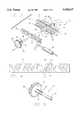
- FIG. 1is an isometric view of a lap-top computer having an IC card mounted therein, with the connector assembly of the inventions/connected to the card.
- FIG. 2is an exploded isometric view of the connector assembly and the rear portion of an IC card with which the connector assembly mates.
- FIG. 3is an exploded isometric view showing components of the connector assembly shown in FIG. 2, with a cable having conductors connected to a printed circuit board used in the assembly.
- FIG. 4is a plan view of the printed circuit board shown in FIG. 3.
- FIG. 5is an enlarged, isometric view of the cam shaft and actuator used in the connector assembly.
- FIG. 6is a front elevation view of the connector assembly of FIG. 2.
- FIG. 7is a bottom view of the connector assembly of FIG. 2, including a sectional view of a portion of the input/output connector used in the IC card.
- FIG. 8is a rear elevation view of the connector assembly of FIG. 2.
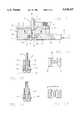
- FIG. 9is a partial, horizontal sectional view taken along line 9--9 FIG. 8.
- FIG. 10is a vertical sectional view taken along line 10--10 of FIG. 7 showing the cam shaft of the invention in its locked position.
- FIG. 11is a transverse sectional view taken along line 11--11 of FIG. 7, showing the cam shaft of the invention in its locked position.
- FIGS. 12 and 13are sectional views similar to FIGS. 10 and 11, but showing the cam shaft in its unlocked position.
- FIG. 14is a vertical sectional view taken along line 14--14 of FIG. 9.
- FIG. 15is a bottom view of an alternative embodiment of the connector assembly of the invention.
- FIG. 16is a rear elevation view of the connector assembly illustrated in FIG. 15.
- FIG. 1a lap-top computer 10 having a port 12 opening at its side, in which an IC card 14 is mounted.
- a cable assembly, generally designated 16comprises the connector assembly 18 of the present invention, and a cable 20.
- the connector assemblyis shown connected to the exposed end of the IC card 12.
- FIG. 2shows the connector assembly 18 positioned to mate with the rear portion 22 of the IC card 14.
- the connector assemblycomprises an insulative housing 24 having a forward end 26, a rear end 28, and opposite sides 30 and 32.
- An extension 34is formed on the side 32 through which the cable 20 enters the housing 24.
- the connector assemblyincludes a plug header 36, a printed circuit board 38, and a cam shaft 40.
- the header 36comprises an insulative body 42 formed with four plug parts 44, 46, 48, and 50.
- a row of pin contacts 52are mounted in the connector body 42. The mating ends of the contacts extend into the respective plug parts 44-50.
- the IC card 14includes an insulative rectangular frame 54 having a receptacle connector 56 located at the rear portion 22 of the frame.
- the receptacle connector 56is formed with recesses 58, 60, 62, and 64 that slidably receive the plug parts 44-50 of the connector assembly 18 when the assembly is connected to the receptacle connector at the rear of the IC card.
- Socket contacts (not shown) mounted in the connector 56extend into the recesses 58-64. The socket contacts engage the pin contacts 52 when the connector assembly 18 is mated with the receptacle connector 56.
- Metal covers 66 and 68are mounted on opposite sides of the frame 54 to enclose a printed circuit board (not shown) mounted within the card.
- the connector assembly 18includes a latching mechanism, generally designated 70, for latching and locking the plug header 36 of the connector assembly to the receptacle connector 56 of the IC card.
- the latching assemblyincludes two resilient latch arms 72 and 74 that extend forwardly from the body 42 of the plug header between the two plug parts 46 and 48.
- the latch armsare integrally formed with the body 42 to reduce the number of parts required to form the assembly.
- the latch armsare designed to be received in a central recess 76 in the receptacle connector 56 of the IC card.
- the latch armsare deflected together as they are pushed into the recess 76.
- Outwardly extending projections 78are formed at the forward ends of the arms.
- the armsspring outwardly to their normal position, whereupon the projections 78 on the arms engage rearwardly-facing shoulders 80 formed at the rear of the walls of the central recess 76.
- the forward ends of the latch arms 72 and 74are shown in phantom, in a latched position within the recess 76. The arms resist rearward movement of the connector assembly 18 but, by themselves, do not lock the connector assembly to the IC card.
- the latching mechanism 70also includes the cam shaft 40.
- the cam shaft 40includes a forward cam portion 80 and a rear detent portion 82.
- the forward cam portion 80has an elliptical-shaped cross-section.
- Four longitudinally extending detent ribs 84are formed on the rear portion 82 of the cam shaft. The ribs are offset from each other by an angle of 90°. Two of the ribs are aligned with the major axis of the elliptical-shaped cam portion 80 of the shaft 40, while the other two ribs are aligned with the minor axis of the elliptical-shaped cam portion.
- An actuator 86is integrally formed on the cam shaft 40 spaced behind the detent ribs 84.
- the actuatoris in the form of a circular knob or disc that has serrations 88 on its outer surface to facilitate manual operation of the actuator.
- the cam shaft 40includes a short rear stub portion 90 that extends rearwardly from the rear face 92 of the actuator.
- the cam shaft 40 with the actuator 86 thereonis a one-piece molded part.
- a boss 94extends rearwardly from the central part of the body 42 of the plug header 36.
- the bosshas a central bore 96 which rotatably receives the forward cam portion 80 of the cam shaft.
- the printed circuit board 38is mounted vertically in the connector housing 24, flush with the rear face 98 of the body 42 of the plug header.
- the printed circuit boardis provided with a row of plated-through holes 100 that are aligned with the contacts 52 in the plug header.
- the plated-through holesare electrically connected to conductive pads 102 on the board by traces 104.
- the boss 94 on the rear of the plug header 36has three flat upwardly-facing surfaces 106, and a semi-cylindrical lower surface 108.
- the printed circuit board 38is formed with a central aperture 110 having a configuration complementary to the outer surface of the boss 94 so as to slidably receive the boss in only one position of the printed circuit board when the board is mounted flush against the rear face of the plug header.
- the tails 110 at the rear of the contacts 52 in the plug headerextend a short distance through the plated-through holes in the printed circuit board, as seen in FIG. 9.
- the tailsPreferably the tails have a press-fit connection with the plating in the holes. Solder may also be added to the rear ends of the tails to enhance the electrical connection.
- the conductors 112(only three being shown for purposes of simplicity) of the cable 20 are soldered at their ends to respective conductive pads 102 on the printed circuit board.
- the contacts 52 in the plug header 36are electrically connected to the conductors 112 of the cable via the plated-through holes 100, conductive traces 104, and the conductive pads 102 on the printed circuit board.
- the housing 24 of the connector assembly 18includes a pre-mold section 120 and an over-mold section 122.
- the pre-mold sectionmay be formed of a slightly resilient thermoplastic material, while the over-mold section is preferably formed of a more flexible type thermoplastic material, which allows the extension 34 of the housing to function as a strain relief for the cable.
- a vertical slot 124is formed in a central portion 126 of the over-mold section 122 of the connector housing. The slot opens at the upper surface 128 and lower surface 130 of the housing.
- the cam shaft 40is mounted in the connector housing with the actuator 86 positioned in the slot 124. The diameter of the actuator 86 is such that the periphery of the actuator extends outwardly beyond the upper surface 128 and lower surface 130 of the housing a short distance, sufficient to allow the user to rotate the actuator with his fingers.
- the rear stub portion 90 of the cam shaftis rotatable in a bore 132 that opens into the slot 124 in the over-mold section 122.
- that portion of the rear detent portion 82 of the cam shaft formed with the detent ribs 84is located in a bore 134 formed in the pre-mold section 120 of the connector housing.
- Four grooves 136are formed in the wall of the bore 134 displaced 90° with respect to each other. The grooves are shaped to receive the detent ribs 84 on the cam shaft.
- FIGS. 10 and 11 of the drawingsshow the cam shaft in a locked position, wherein the forward elliptical-shaped cam portion 80 of the shaft is positioned with its major axis lying in a horizontal plane, thereby blocking the latch arms 72 and 74 of the latching mechanism from being deflected toward each other.
- the connector assembly 18cannot be disconnected from the receptacle connector 56 of the IC card.
- the cam shaft 40is rotated 90° from the position shown in FIGS. 10 and 11, to the position shown in FIGS. 12 and 13.
- the elliptical-shaped forward cam portion 18 of the cam shaftis then positioned with its major axis extending in a vertical plane, thereby providing a space between the cam shaft and the latch arms.
- the latch arms 72 and 74 of the latching mechanismwill be deflected toward each other so that the connector assembly can be disconnected from the receptacle connector of the IC card.
- the connector assembly of the inventionmay have a relatively short profile.
- the short profile of the connectoris enhanced by the fact that the actuator 86 for the cam shaft extends rearwardly no further than the rear end 28 of the connector housing 24, and the printed circuit board 38 is mounted vertically within the housing 24.
- FIGS. 15 and 16An alternative embodiment of the invention is shown in FIGS. 15 and 16.
- the actuator 86is disposed behind the rear end 28 of the connector housing. This arrangement results in some sacrifice in the length of the connector assembly in the longitudinal extent of the assembly.
- the rotatable cam shaftis shown to be operated by an integral actuator 86, it will be appreciated that the cam shaft could also be oscillated over a 90° angle by a push button slidable on the connector housing parallel to the plane P shown in FIG. 7, with a suitable pin and slot interconnection arrangement between the shaft and the push button (not shown).
- the connector assembly of the present inventionhas the advantage that it has a relatively short profile, and requires only a minimum number of parts. Further, since the cable 20 is connected at the side of the housing of the connector assembly, rather than at the rear, the cable will extend in a rearward direction out of the way of the user when the connector assembly is coupled to an IC card mounted in the side of a computer, as seen in FIG. 1.
- the connector assemblymay be used in any orientation with respect to gravity.
Landscapes
- Details Of Connecting Devices For Male And Female Coupling (AREA)
- Coupling Device And Connection With Printed Circuit (AREA)
Abstract
Description
Claims (18)
Priority Applications (7)
| Application Number | Priority Date | Filing Date | Title |
|---|---|---|---|
| US08/398,026US5538437A (en) | 1995-03-03 | 1995-03-03 | Connector assembly for IC card |
| CA002168399ACA2168399C (en) | 1995-03-03 | 1996-01-30 | Connector assembly for ic card |
| TW085101202ATW437124B (en) | 1995-03-03 | 1996-01-31 | Connector assembly for IC card |
| EP96102865AEP0730323B1 (en) | 1995-03-03 | 1996-03-01 | Connector assembly for IC card |
| CN96104223ACN1098546C (en) | 1995-03-03 | 1996-03-01 | Connector assembly for IC card |
| DE69624160TDE69624160T2 (en) | 1995-03-03 | 1996-03-01 | Connector arrangement for integrated circuit card |
| JP8046072AJP2880681B2 (en) | 1995-03-03 | 1996-03-04 | Connector device |
Applications Claiming Priority (1)
| Application Number | Priority Date | Filing Date | Title |
|---|---|---|---|
| US08/398,026US5538437A (en) | 1995-03-03 | 1995-03-03 | Connector assembly for IC card |
Publications (1)
| Publication Number | Publication Date |
|---|---|
| US5538437Atrue US5538437A (en) | 1996-07-23 |
Family
ID=23573695
Family Applications (1)
| Application Number | Title | Priority Date | Filing Date |
|---|---|---|---|
| US08/398,026Expired - LifetimeUS5538437A (en) | 1995-03-03 | 1995-03-03 | Connector assembly for IC card |
Country Status (7)
| Country | Link |
|---|---|
| US (1) | US5538437A (en) |
| EP (1) | EP0730323B1 (en) |
| JP (1) | JP2880681B2 (en) |
| CN (1) | CN1098546C (en) |
| CA (1) | CA2168399C (en) |
| DE (1) | DE69624160T2 (en) |
| TW (1) | TW437124B (en) |
Cited By (35)
| Publication number | Priority date | Publication date | Assignee | Title |
|---|---|---|---|---|
| WO1997044867A1 (en)* | 1996-05-24 | 1997-11-27 | Itt Manufacturing Enterprises, Inc. | Smart card computer adaptor |
| EP0880106A3 (en)* | 1997-05-21 | 2000-07-05 | Itt Manufacturing Enterprises, Inc. | Smart card adaptor latch |
| US6146180A (en)* | 1999-11-12 | 2000-11-14 | Itt Manufacturing Enterprises, Inc. | Connector latch with integrated auxiliary contacts |
| EP1111728A3 (en)* | 1999-12-21 | 2001-12-12 | Japan Aviation Electronics Industry Limited | Connector with an improved guide portion for guiding connection of the connector and an object to be connected thereto |
| USD455401S1 (en) | 2000-09-21 | 2002-04-09 | Sony Computer Entertainment Inc. | Electric connector |
| EP1137115A3 (en)* | 2000-01-25 | 2002-04-10 | AMPHENOL-TUCHEL ELECTRONICS GmbH | Electrical plug |
| US6446863B1 (en)* | 1999-07-09 | 2002-09-10 | Fujitsu Limited | Electronic apparatus with a card detachably inserted |
| US6598279B1 (en) | 1998-08-21 | 2003-07-29 | Micron Technology, Inc. | Multiple connection socket assembly for semiconductor fabrication equipment and methods employing same |
| US20030203672A1 (en)* | 2002-04-24 | 2003-10-30 | Tafoya Anthony S. | Retainer bracket for connectors |
| US20040242061A1 (en)* | 2003-01-15 | 2004-12-02 | Gledhill Dale C. | Connection box stabilizer |
| WO2004114470A1 (en)* | 2003-06-26 | 2004-12-29 | Benq Mobile Gmbh & Co. Ohg | Plug assembly for producing an electrical and mechanical connection |
| US6840800B2 (en)* | 2001-10-10 | 2005-01-11 | Quixemble, Inc. | Deflecting securement anchor for electrical fixtures |
| US6908324B1 (en)* | 2000-09-08 | 2005-06-21 | 3Com Corporation | Connector scheme to allow physical orientation of a computer peripheral |
| US20050181665A1 (en)* | 2001-03-06 | 2005-08-18 | Kidman Brent L. | Connection box stabilizer |
| US7074070B1 (en)* | 2005-06-17 | 2006-07-11 | Cheng Uei Precision Industry Co., Ltd. | Connector assembly with latch mechanism |
| US20060246764A1 (en)* | 2004-02-25 | 2006-11-02 | Hon Hai Precision Ind. Co., Ltd. | Cable assembly having locking member |
| EP1833126A2 (en) | 2006-03-09 | 2007-09-12 | Phoenix Contact GmbH & Co. KG | Connecting plug |
| US7306482B1 (en) | 2001-03-06 | 2007-12-11 | Cheetah Usa Corp. | Electrical connection box |
| EP2115826A2 (en)* | 2007-02-23 | 2009-11-11 | Fci | Electrical connector |
| EP1981127A3 (en)* | 2007-04-11 | 2009-12-23 | Weidmüller Interface GmbH & Co. KG | Connector, in particular for circuit boards |
| WO2010110855A1 (en)* | 2009-03-24 | 2010-09-30 | Tyco Electronics Corporation | Connector assembly with a latch |
| US20100291788A1 (en)* | 2009-05-14 | 2010-11-18 | Hon Hai Precision Industry Co., Ltd. | Electrical connector with latch |
| US20110189880A1 (en)* | 2010-02-01 | 2011-08-04 | Sonion A/S | assembly comprising a male and a female plug member, a male plug member and a female plug member |
| US8029301B2 (en) | 2005-01-11 | 2011-10-04 | Cheetah Usa Corp. | Wide safety strap for electrical fixtures |
| EP2302740A4 (en)* | 2008-12-17 | 2011-11-23 | Hytera Comm Corp Ltd | Connector |
| US8109785B2 (en) | 2001-03-06 | 2012-02-07 | Cheetah Usa Corp. | Connection box assembly method |
| US8299359B2 (en) | 2006-07-18 | 2012-10-30 | Leviton Manufacturing Company, Inc. | Wiring device and cover plate snap-on assembly |
| US20140302694A1 (en)* | 2011-11-23 | 2014-10-09 | 3M Innovative Properties Company | Latching Connector Assembly |
| US20150126075A1 (en)* | 2013-11-05 | 2015-05-07 | Bellwether Electronic Corp. | Power plug and power receptacle |
| US20160240975A1 (en)* | 2013-11-05 | 2016-08-18 | Bellwether Electronic Corp. | Power plug, power receptacle and power connector assembly |
| US9735502B2 (en) | 2013-12-13 | 2017-08-15 | Hewlett Packard Enterprise Development Lp | Connector with a retainer assembly |
| US20190089094A1 (en)* | 2017-09-18 | 2019-03-21 | Boston Warehouse | Electro-mechanical coupler for artificial tree sections |
| US11171438B2 (en)* | 2020-04-09 | 2021-11-09 | Energy Services LLC | Unitized cable plug array for mobile power generation equipment |
| US20210408727A1 (en)* | 2020-06-28 | 2021-12-30 | Amphenol Commercial Products (Chengdu) Co., Ltd. | Electrical connector and method for mating and unmating the same |
| EP4325672A1 (en)* | 2022-08-16 | 2024-02-21 | Franz Binder GmbH + Co. Elektrische Bauelemente KG | Electrical connector and connector system |
Families Citing this family (1)
| Publication number | Priority date | Publication date | Assignee | Title |
|---|---|---|---|---|
| JP3269029B2 (en)* | 1998-06-16 | 2002-03-25 | エスエムケイ株式会社 | Connector lock structure |
Citations (21)
| Publication number | Priority date | Publication date | Assignee | Title |
|---|---|---|---|---|
| US2654872A (en)* | 1951-09-21 | 1953-10-06 | Raytheon Mfg Co | Electrical connector |
| US3501735A (en)* | 1968-06-21 | 1970-03-17 | Westinghouse Electric Corp | Latchable electrical connector assemblage |
| US3587037A (en)* | 1968-10-25 | 1971-06-22 | Itt | Low insertion force connector assembly |
| US3646501A (en)* | 1968-10-24 | 1972-02-29 | Nokia Oy Ab | Connecting plug for a current supply rail arrangement intended particularly for lighting purposes and small-sized electrical motors |
| US3848222A (en)* | 1973-07-18 | 1974-11-12 | Amp Inc | Zero entry connector system |
| US3977749A (en)* | 1975-01-29 | 1976-08-31 | International Telephone And Telegraph Corporation | Electronic packaging assembly |
| US4083619A (en)* | 1977-06-20 | 1978-04-11 | Automation Industries, Inc. | Electrical connector |
| US4265503A (en)* | 1979-12-20 | 1981-05-05 | Automation Industries, Inc. | Aircraft/pylon multi-contact electrical connector |
| US4362348A (en)* | 1980-07-03 | 1982-12-07 | Automation Industries, Inc. | EMI: X-Ray protected multi-contact connector |
| US4504101A (en)* | 1983-08-29 | 1985-03-12 | Gte Automatic Electric Inc. | Low insertion force connection arrangement |
| US4505527A (en)* | 1983-08-29 | 1985-03-19 | Gte Automatic Electric Inc. | Low insertion force connection arrangement |
| US4591219A (en)* | 1983-08-29 | 1986-05-27 | Gte Communication Systems Corporation | Low insertion force connection arrangement |
| US4591217A (en)* | 1983-08-29 | 1986-05-27 | Gte Communication Systems Corporation | Low insertion force connection arrangement |
| US4591619A (en)* | 1981-12-11 | 1986-05-27 | Denki Kagaku Kogyo Kabushiki Kaisha | Process for producing an iminated copolymer |
| US4597620A (en)* | 1984-02-13 | 1986-07-01 | J. B. Nottingham & Co., Inc. | Electrical connector and method of using it |
| US4695111A (en)* | 1986-04-10 | 1987-09-22 | Amp Incorporated | Zero insertion force connector having wiping action |
| US4810206A (en)* | 1986-11-25 | 1989-03-07 | Kings Electronics Co., Inc. | Locking electrical connector |
| US4838808A (en)* | 1987-07-17 | 1989-06-13 | Amp Incorporated | Shielded electrical connector and latch mechanism therefor |
| US5368496A (en)* | 1993-12-10 | 1994-11-29 | Tetrad Corporation | Connector assembly having control lever actuation |
| US5387110A (en)* | 1993-11-12 | 1995-02-07 | International Business Machines Corporation | Reversible dual media adapter cable |
| US5411402A (en)* | 1993-12-17 | 1995-05-02 | Itt Corporation | Connector assembly for IC card |
Family Cites Families (6)
| Publication number | Priority date | Publication date | Assignee | Title |
|---|---|---|---|---|
| JPH0357028Y2 (en)* | 1985-04-26 | 1991-12-25 | ||
| US4998842A (en)* | 1990-04-30 | 1991-03-12 | The United States Of America As Represented By The Administrator Of The National Aeronautics And Space Administration | Overcenter collet space station truss fastener |
| US5186567A (en)* | 1992-01-15 | 1993-02-16 | The United States Of America As Represented By The Administrator Of The National Aeronautics And Space Administration | Quick-connect fasteners for assembling devices in space |
| JPH05190231A (en)* | 1992-01-16 | 1993-07-30 | Fujitsu Ltd | Fitting/removing structure of connector housing |
| JP2576461Y2 (en)* | 1992-09-28 | 1998-07-09 | 双葉電子工業株式会社 | Connection cord connector |
| US5439310A (en)* | 1993-05-25 | 1995-08-08 | The United States Of America As Represented By United States National Aeronautics And Space Administration | Connector systems for structures |
- 1995
- 1995-03-03USUS08/398,026patent/US5538437A/ennot_activeExpired - Lifetime
- 1996
- 1996-01-30CACA002168399Apatent/CA2168399C/ennot_activeExpired - Lifetime
- 1996-01-31TWTW085101202Apatent/TW437124B/ennot_activeIP Right Cessation
- 1996-03-01DEDE69624160Tpatent/DE69624160T2/ennot_activeExpired - Lifetime
- 1996-03-01CNCN96104223Apatent/CN1098546C/ennot_activeExpired - Lifetime
- 1996-03-01EPEP96102865Apatent/EP0730323B1/ennot_activeExpired - Lifetime
- 1996-03-04JPJP8046072Apatent/JP2880681B2/ennot_activeExpired - Fee Related
Patent Citations (21)
| Publication number | Priority date | Publication date | Assignee | Title |
|---|---|---|---|---|
| US2654872A (en)* | 1951-09-21 | 1953-10-06 | Raytheon Mfg Co | Electrical connector |
| US3501735A (en)* | 1968-06-21 | 1970-03-17 | Westinghouse Electric Corp | Latchable electrical connector assemblage |
| US3646501A (en)* | 1968-10-24 | 1972-02-29 | Nokia Oy Ab | Connecting plug for a current supply rail arrangement intended particularly for lighting purposes and small-sized electrical motors |
| US3587037A (en)* | 1968-10-25 | 1971-06-22 | Itt | Low insertion force connector assembly |
| US3848222A (en)* | 1973-07-18 | 1974-11-12 | Amp Inc | Zero entry connector system |
| US3977749A (en)* | 1975-01-29 | 1976-08-31 | International Telephone And Telegraph Corporation | Electronic packaging assembly |
| US4083619A (en)* | 1977-06-20 | 1978-04-11 | Automation Industries, Inc. | Electrical connector |
| US4265503A (en)* | 1979-12-20 | 1981-05-05 | Automation Industries, Inc. | Aircraft/pylon multi-contact electrical connector |
| US4362348A (en)* | 1980-07-03 | 1982-12-07 | Automation Industries, Inc. | EMI: X-Ray protected multi-contact connector |
| US4591619A (en)* | 1981-12-11 | 1986-05-27 | Denki Kagaku Kogyo Kabushiki Kaisha | Process for producing an iminated copolymer |
| US4505527A (en)* | 1983-08-29 | 1985-03-19 | Gte Automatic Electric Inc. | Low insertion force connection arrangement |
| US4591219A (en)* | 1983-08-29 | 1986-05-27 | Gte Communication Systems Corporation | Low insertion force connection arrangement |
| US4591217A (en)* | 1983-08-29 | 1986-05-27 | Gte Communication Systems Corporation | Low insertion force connection arrangement |
| US4504101A (en)* | 1983-08-29 | 1985-03-12 | Gte Automatic Electric Inc. | Low insertion force connection arrangement |
| US4597620A (en)* | 1984-02-13 | 1986-07-01 | J. B. Nottingham & Co., Inc. | Electrical connector and method of using it |
| US4695111A (en)* | 1986-04-10 | 1987-09-22 | Amp Incorporated | Zero insertion force connector having wiping action |
| US4810206A (en)* | 1986-11-25 | 1989-03-07 | Kings Electronics Co., Inc. | Locking electrical connector |
| US4838808A (en)* | 1987-07-17 | 1989-06-13 | Amp Incorporated | Shielded electrical connector and latch mechanism therefor |
| US5387110A (en)* | 1993-11-12 | 1995-02-07 | International Business Machines Corporation | Reversible dual media adapter cable |
| US5368496A (en)* | 1993-12-10 | 1994-11-29 | Tetrad Corporation | Connector assembly having control lever actuation |
| US5411402A (en)* | 1993-12-17 | 1995-05-02 | Itt Corporation | Connector assembly for IC card |
Cited By (52)
| Publication number | Priority date | Publication date | Assignee | Title |
|---|---|---|---|---|
| CN100355156C (en)* | 1996-05-24 | 2007-12-12 | Itt制造企业公司 | Smart card computer adaptor |
| WO1997044867A1 (en)* | 1996-05-24 | 1997-11-27 | Itt Manufacturing Enterprises, Inc. | Smart card computer adaptor |
| EP0880106A3 (en)* | 1997-05-21 | 2000-07-05 | Itt Manufacturing Enterprises, Inc. | Smart card adaptor latch |
| US6149450A (en)* | 1997-05-21 | 2000-11-21 | Itt Manufacturing Enterprises, Inc. | Smart card adapter latch |
| US6598279B1 (en) | 1998-08-21 | 2003-07-29 | Micron Technology, Inc. | Multiple connection socket assembly for semiconductor fabrication equipment and methods employing same |
| US6446863B1 (en)* | 1999-07-09 | 2002-09-10 | Fujitsu Limited | Electronic apparatus with a card detachably inserted |
| US6146180A (en)* | 1999-11-12 | 2000-11-14 | Itt Manufacturing Enterprises, Inc. | Connector latch with integrated auxiliary contacts |
| EP1111728A3 (en)* | 1999-12-21 | 2001-12-12 | Japan Aviation Electronics Industry Limited | Connector with an improved guide portion for guiding connection of the connector and an object to be connected thereto |
| EP1137115A3 (en)* | 2000-01-25 | 2002-04-10 | AMPHENOL-TUCHEL ELECTRONICS GmbH | Electrical plug |
| US6908324B1 (en)* | 2000-09-08 | 2005-06-21 | 3Com Corporation | Connector scheme to allow physical orientation of a computer peripheral |
| USD455401S1 (en) | 2000-09-21 | 2002-04-09 | Sony Computer Entertainment Inc. | Electric connector |
| US7306482B1 (en) | 2001-03-06 | 2007-12-11 | Cheetah Usa Corp. | Electrical connection box |
| US7083467B2 (en) | 2001-03-06 | 2006-08-01 | Quixemble, Inc. | Connection box stabilizer |
| US8109785B2 (en) | 2001-03-06 | 2012-02-07 | Cheetah Usa Corp. | Connection box assembly method |
| US20050181665A1 (en)* | 2001-03-06 | 2005-08-18 | Kidman Brent L. | Connection box stabilizer |
| US6840800B2 (en)* | 2001-10-10 | 2005-01-11 | Quixemble, Inc. | Deflecting securement anchor for electrical fixtures |
| US6802722B2 (en)* | 2002-04-24 | 2004-10-12 | Honeywell International Inc. | Retainer bracket for connectors |
| US20030203672A1 (en)* | 2002-04-24 | 2003-10-30 | Tafoya Anthony S. | Retainer bracket for connectors |
| US7049511B2 (en) | 2003-01-15 | 2006-05-23 | Quixemble, Inc. | Connection box stabilizer |
| US20040242061A1 (en)* | 2003-01-15 | 2004-12-02 | Gledhill Dale C. | Connection box stabilizer |
| WO2004114470A1 (en)* | 2003-06-26 | 2004-12-29 | Benq Mobile Gmbh & Co. Ohg | Plug assembly for producing an electrical and mechanical connection |
| US20060246764A1 (en)* | 2004-02-25 | 2006-11-02 | Hon Hai Precision Ind. Co., Ltd. | Cable assembly having locking member |
| US7264496B2 (en)* | 2004-02-25 | 2007-09-04 | Hon Hai Precision Ind. Co., Ltd. | Cable assembly having locking member on opposite sides thereof |
| US8029301B2 (en) | 2005-01-11 | 2011-10-04 | Cheetah Usa Corp. | Wide safety strap for electrical fixtures |
| US7074070B1 (en)* | 2005-06-17 | 2006-07-11 | Cheng Uei Precision Industry Co., Ltd. | Connector assembly with latch mechanism |
| EP1833126A2 (en) | 2006-03-09 | 2007-09-12 | Phoenix Contact GmbH & Co. KG | Connecting plug |
| EP1833126A3 (en)* | 2006-03-09 | 2008-11-05 | Phoenix Contact GmbH & Co. KG | Connecting plug |
| US8299359B2 (en) | 2006-07-18 | 2012-10-30 | Leviton Manufacturing Company, Inc. | Wiring device and cover plate snap-on assembly |
| EP2115826A2 (en)* | 2007-02-23 | 2009-11-11 | Fci | Electrical connector |
| EP1981127A3 (en)* | 2007-04-11 | 2009-12-23 | Weidmüller Interface GmbH & Co. KG | Connector, in particular for circuit boards |
| EP2302740A4 (en)* | 2008-12-17 | 2011-11-23 | Hytera Comm Corp Ltd | Connector |
| US7972164B2 (en) | 2009-03-24 | 2011-07-05 | Tyco Electronics Corporation | Connector assembly with a latch |
| US20100248553A1 (en)* | 2009-03-24 | 2010-09-30 | Alan Bucher | Connector assembly with a latch |
| CN102369637A (en)* | 2009-03-24 | 2012-03-07 | 泰科电子公司 | Connector assembly with latch |
| WO2010110855A1 (en)* | 2009-03-24 | 2010-09-30 | Tyco Electronics Corporation | Connector assembly with a latch |
| KR101257617B1 (en)* | 2009-03-24 | 2013-04-29 | 타이코 일렉트로닉스 코포레이션 | Connector assembly with a latch |
| US8007305B2 (en)* | 2009-05-14 | 2011-08-30 | Hon Hai Precision Ind. Co., Ltd. | Electrical connector with latch |
| US20100291788A1 (en)* | 2009-05-14 | 2010-11-18 | Hon Hai Precision Industry Co., Ltd. | Electrical connector with latch |
| US20110189880A1 (en)* | 2010-02-01 | 2011-08-04 | Sonion A/S | assembly comprising a male and a female plug member, a male plug member and a female plug member |
| US8313336B2 (en)* | 2010-02-01 | 2012-11-20 | Sonion A/S | Assembly comprising a male and a female plug member, a male plug member and a female plug member |
| US20140302694A1 (en)* | 2011-11-23 | 2014-10-09 | 3M Innovative Properties Company | Latching Connector Assembly |
| US9595787B2 (en)* | 2011-11-23 | 2017-03-14 | 3M Innovative Properties Company | Latching connector assembly |
| US20150126075A1 (en)* | 2013-11-05 | 2015-05-07 | Bellwether Electronic Corp. | Power plug and power receptacle |
| US20160240975A1 (en)* | 2013-11-05 | 2016-08-18 | Bellwether Electronic Corp. | Power plug, power receptacle and power connector assembly |
| US9614329B2 (en)* | 2013-11-05 | 2017-04-04 | Bellwether Electronic Corp | Power plug, power receptacle and power connector assembly |
| US9735502B2 (en) | 2013-12-13 | 2017-08-15 | Hewlett Packard Enterprise Development Lp | Connector with a retainer assembly |
| US20190089094A1 (en)* | 2017-09-18 | 2019-03-21 | Boston Warehouse | Electro-mechanical coupler for artificial tree sections |
| US10498074B2 (en)* | 2017-09-18 | 2019-12-03 | Boston Warehouse | Electro-mechanical coupler for artificial tree sections |
| US11171438B2 (en)* | 2020-04-09 | 2021-11-09 | Energy Services LLC | Unitized cable plug array for mobile power generation equipment |
| US20210408727A1 (en)* | 2020-06-28 | 2021-12-30 | Amphenol Commercial Products (Chengdu) Co., Ltd. | Electrical connector and method for mating and unmating the same |
| US11777256B2 (en)* | 2020-06-28 | 2023-10-03 | Amphenol Commercial Products (Chengdu) Co., Ltd. | Electrical connector and method for mating and unmating the same |
| EP4325672A1 (en)* | 2022-08-16 | 2024-02-21 | Franz Binder GmbH + Co. Elektrische Bauelemente KG | Electrical connector and connector system |
Also Published As
| Publication number | Publication date |
|---|---|
| EP0730323A2 (en) | 1996-09-04 |
| TW437124B (en) | 2001-05-28 |
| JPH097691A (en) | 1997-01-10 |
| CN1135053A (en) | 1996-11-06 |
| EP0730323B1 (en) | 2002-10-09 |
| JP2880681B2 (en) | 1999-04-12 |
| DE69624160D1 (en) | 2002-11-14 |
| DE69624160T2 (en) | 2003-06-18 |
| CN1098546C (en) | 2003-01-08 |
| CA2168399A1 (en) | 1996-09-04 |
| EP0730323A3 (en) | 1997-08-13 |
| CA2168399C (en) | 2000-01-04 |
Similar Documents
| Publication | Publication Date | Title |
|---|---|---|
| US5538437A (en) | Connector assembly for IC card | |
| EP0305101B1 (en) | Connector system having combined latch and polerization member | |
| CN108429075B (en) | Connector with coupling device for stabilizing latch | |
| EP0734599B1 (en) | Connector assembly for ic card | |
| US6517372B1 (en) | Quick release shock/vibration connector assembly | |
| US6280227B1 (en) | Electrical connector with locking mechanism and metal spring | |
| WO1986000473A1 (en) | Printed circuit board header having coaxial sockets therein and matable coaxial plug housing | |
| EP0630080B1 (en) | Circuit board mountable modular phone jack | |
| US6866533B2 (en) | Cable connector assembly having pull tab | |
| US5468156A (en) | Locking system for interconnection of daughter board and mother board assemblies | |
| US5273453A (en) | Electrical connector with positive latch | |
| EP0929125B1 (en) | Connector latch with tubular hinge | |
| EP0880106B1 (en) | Smart card adaptor latch | |
| CA2179372C (en) | Latch for ic card connector | |
| US20210075158A1 (en) | Plug connector | |
| EP0646993B1 (en) | Electrical connector assembly with cam lever lock mechanism | |
| US6663428B1 (en) | Electrical connector with improved grounding terminal arrangement | |
| US5683264A (en) | PCMCI cable connector with latching indicator | |
| US7845960B2 (en) | Electrical connector for receiving an electrical card assembly | |
| US6957975B2 (en) | Plug connector housing with locking mechanism and plug connector having such housing | |
| JP4074022B2 (en) | Shield connector | |
| US4838807A (en) | Electrical connector latching mechanism | |
| JPH0360315A (en) | Latch for electric connector | |
| HK1000406B (en) | Connector system having combined latch and polerization member |
Legal Events
| Date | Code | Title | Description |
|---|---|---|---|
| AS | Assignment | Owner name:ITT INDUSTRIES, INC., NEW YORK Free format text:ASSIGNMENT OF ASSIGNORS INTEREST;ASSIGNORS:BATES, CHARLES LINSDAY, III;BETHURUM, GARY CAIN;REEL/FRAME:007374/0798 Effective date:19950227 | |
| STCF | Information on status: patent grant | Free format text:PATENTED CASE | |
| FEPP | Fee payment procedure | Free format text:PAYOR NUMBER ASSIGNED (ORIGINAL EVENT CODE: ASPN); ENTITY STATUS OF PATENT OWNER: LARGE ENTITY | |
| FPAY | Fee payment | Year of fee payment:4 | |
| AS | Assignment | Owner name:ITT MANUFACTURING ENTERPRISES, INC., DELAWARE Free format text:ASSIGNMENT OF ASSIGNORS INTEREST;ASSIGNOR:ITT INDUSTRIES, INC.;REEL/FRAME:010859/0033 Effective date:20000404 | |
| FPAY | Fee payment | Year of fee payment:8 | |
| AS | Assignment | Owner name:LENOVO (SINGAPORE) PTE LTD.,SINGAPORE Free format text:ASSIGNMENT OF ASSIGNORS INTEREST;ASSIGNOR:INTERNATIONAL BUSINESS MACHINES CORPORATION;REEL/FRAME:016891/0507 Effective date:20050520 Owner name:LENOVO (SINGAPORE) PTE LTD., SINGAPORE Free format text:ASSIGNMENT OF ASSIGNORS INTEREST;ASSIGNOR:INTERNATIONAL BUSINESS MACHINES CORPORATION;REEL/FRAME:016891/0507 Effective date:20050520 | |
| FPAY | Fee payment | Year of fee payment:12 | |
| REMI | Maintenance fee reminder mailed | ||
| AS | Assignment | Owner name:LENOVO PC INTERNATIONAL, HONG KONG Free format text:NUNC PRO TUNC ASSIGNMENT;ASSIGNOR:LENOVO (SINGAPORE) PTE LTD.;REEL/FRAME:037160/0001 Effective date:20130401 |