US5538405A - Peristaltic pulse pumping systems and methods - Google Patents
Peristaltic pulse pumping systems and methodsDownload PDFInfo
- Publication number
- US5538405A US5538405AUS08/269,933US26993394AUS5538405AUS 5538405 AUS5538405 AUS 5538405AUS 26993394 AUS26993394 AUS 26993394AUS 5538405 AUS5538405 AUS 5538405A
- Authority
- US
- United States
- Prior art keywords
- cassette
- rotor
- processing
- valve
- tubing
- Prior art date
- Legal status (The legal status is an assumption and is not a legal conclusion. Google has not performed a legal analysis and makes no representation as to the accuracy of the status listed.)
- Expired - Lifetime
Links
- 230000002572peristaltic effectEffects0.000titleclaimsabstractdescription18
- 238000005086pumpingMethods0.000titleclaimsabstractdescription13
- 238000000034methodMethods0.000titleabstractdescription20
- 238000012545processingMethods0.000description68
- 239000007788liquidSubstances0.000description44
- 239000012530fluidSubstances0.000description43
- 210000003743erythrocyteAnatomy0.000description17
- 210000004623platelet-rich plasmaAnatomy0.000description16
- 210000001113umbilicusAnatomy0.000description13
- 210000004369bloodAnatomy0.000description11
- 239000008280bloodSubstances0.000description11
- 238000010276constructionMethods0.000description9
- 239000003146anticoagulant agentSubstances0.000description8
- 229940127219anticoagulant drugDrugs0.000description8
- 229920003023plasticPolymers0.000description8
- 239000004033plasticSubstances0.000description8
- 230000000712assemblyEffects0.000description7
- 238000000429assemblyMethods0.000description7
- 210000001772blood plateletAnatomy0.000description7
- 238000000926separation methodMethods0.000description7
- 239000000463materialSubstances0.000description5
- FAPWRFPIFSIZLT-UHFFFAOYSA-MSodium chlorideChemical compound[Na+].[Cl-]FAPWRFPIFSIZLT-UHFFFAOYSA-M0.000description4
- 230000001413cellular effectEffects0.000description4
- 239000011780sodium chlorideSubstances0.000description4
- 239000012503blood componentSubstances0.000description3
- 230000012953feeding on blood of other organismEffects0.000description3
- 239000012528membraneSubstances0.000description3
- 230000002093peripheral effectEffects0.000description3
- 210000002381plasmaAnatomy0.000description3
- 238000010926purgeMethods0.000description3
- 230000001225therapeutic effectEffects0.000description3
- 238000013459approachMethods0.000description2
- 239000000306componentSubstances0.000description2
- 230000006870functionEffects0.000description2
- 210000000265leukocyteAnatomy0.000description2
- 230000037452primingEffects0.000description2
- 238000003672processing methodMethods0.000description2
- 239000000243solutionSubstances0.000description2
- 238000003466weldingMethods0.000description2
- 206010018910HaemolysisDiseases0.000description1
- 239000006057Non-nutritive feed additiveSubstances0.000description1
- 239000010836blood and blood productSubstances0.000description1
- 229940125691blood productDrugs0.000description1
- 238000005119centrifugationMethods0.000description1
- 238000006243chemical reactionMethods0.000description1
- 239000000428dustSubstances0.000description1
- 238000001914filtrationMethods0.000description1
- 230000008588hemolysisEffects0.000description1
- 238000002347injectionMethods0.000description1
- 239000007924injectionSubstances0.000description1
- 230000007774longtermEffects0.000description1
- 238000012423maintenanceMethods0.000description1
- 238000012544monitoring processMethods0.000description1
- 229920000915polyvinyl chloridePolymers0.000description1
- 239000004800polyvinyl chlorideSubstances0.000description1
- 230000003134recirculating effectEffects0.000description1
- 238000007789sealingMethods0.000description1
- 239000000725suspensionSubstances0.000description1
- 239000003634thrombocyte concentrateSubstances0.000description1
Images


Classifications
- F—MECHANICAL ENGINEERING; LIGHTING; HEATING; WEAPONS; BLASTING
- F04—POSITIVE - DISPLACEMENT MACHINES FOR LIQUIDS; PUMPS FOR LIQUIDS OR ELASTIC FLUIDS
- F04B—POSITIVE-DISPLACEMENT MACHINES FOR LIQUIDS; PUMPS
- F04B43/00—Machines, pumps, or pumping installations having flexible working members
- F04B43/0009—Special features
- F04B43/0081—Special features systems, control, safety measures
- A—HUMAN NECESSITIES
- A61—MEDICAL OR VETERINARY SCIENCE; HYGIENE
- A61M—DEVICES FOR INTRODUCING MEDIA INTO, OR ONTO, THE BODY; DEVICES FOR TRANSDUCING BODY MEDIA OR FOR TAKING MEDIA FROM THE BODY; DEVICES FOR PRODUCING OR ENDING SLEEP OR STUPOR
- A61M1/00—Suction or pumping devices for medical purposes; Devices for carrying-off, for treatment of, or for carrying-over, body-liquids; Drainage systems
- A61M1/14—Dialysis systems; Artificial kidneys; Blood oxygenators ; Reciprocating systems for treatment of body fluids, e.g. single needle systems for hemofiltration or pheresis
- A61M1/30—Single needle dialysis ; Reciprocating systems, alternately withdrawing blood from and returning it to the patient, e.g. single-lumen-needle dialysis or single needle systems for hemofiltration or pheresis
- A61M1/301—Details
- A61M1/302—Details having a reservoir for withdrawn untreated blood
- A—HUMAN NECESSITIES
- A61—MEDICAL OR VETERINARY SCIENCE; HYGIENE
- A61M—DEVICES FOR INTRODUCING MEDIA INTO, OR ONTO, THE BODY; DEVICES FOR TRANSDUCING BODY MEDIA OR FOR TAKING MEDIA FROM THE BODY; DEVICES FOR PRODUCING OR ENDING SLEEP OR STUPOR
- A61M1/00—Suction or pumping devices for medical purposes; Devices for carrying-off, for treatment of, or for carrying-over, body-liquids; Drainage systems
- A61M1/14—Dialysis systems; Artificial kidneys; Blood oxygenators ; Reciprocating systems for treatment of body fluids, e.g. single needle systems for hemofiltration or pheresis
- A61M1/30—Single needle dialysis ; Reciprocating systems, alternately withdrawing blood from and returning it to the patient, e.g. single-lumen-needle dialysis or single needle systems for hemofiltration or pheresis
- A61M1/301—Details
- A61M1/303—Details having a reservoir for treated blood to be returned
- A—HUMAN NECESSITIES
- A61—MEDICAL OR VETERINARY SCIENCE; HYGIENE
- A61M—DEVICES FOR INTRODUCING MEDIA INTO, OR ONTO, THE BODY; DEVICES FOR TRANSDUCING BODY MEDIA OR FOR TAKING MEDIA FROM THE BODY; DEVICES FOR PRODUCING OR ENDING SLEEP OR STUPOR
- A61M1/00—Suction or pumping devices for medical purposes; Devices for carrying-off, for treatment of, or for carrying-over, body-liquids; Drainage systems
- A61M1/36—Other treatment of blood in a by-pass of the natural circulatory system, e.g. temperature adaptation, irradiation ; Extra-corporeal blood circuits
- A61M1/3621—Extra-corporeal blood circuits
- A61M1/3622—Extra-corporeal blood circuits with a cassette forming partially or totally the blood circuit
- A61M1/36222—Details related to the interface between cassette and machine
- A61M1/362227—Details related to the interface between cassette and machine the interface providing means for actuating on functional elements of the cassette, e.g. plungers
- A—HUMAN NECESSITIES
- A61—MEDICAL OR VETERINARY SCIENCE; HYGIENE
- A61M—DEVICES FOR INTRODUCING MEDIA INTO, OR ONTO, THE BODY; DEVICES FOR TRANSDUCING BODY MEDIA OR FOR TAKING MEDIA FROM THE BODY; DEVICES FOR PRODUCING OR ENDING SLEEP OR STUPOR
- A61M1/00—Suction or pumping devices for medical purposes; Devices for carrying-off, for treatment of, or for carrying-over, body-liquids; Drainage systems
- A61M1/36—Other treatment of blood in a by-pass of the natural circulatory system, e.g. temperature adaptation, irradiation ; Extra-corporeal blood circuits
- A61M1/3621—Extra-corporeal blood circuits
- A61M1/3622—Extra-corporeal blood circuits with a cassette forming partially or totally the blood circuit
- A61M1/36224—Extra-corporeal blood circuits with a cassette forming partially or totally the blood circuit with sensing means or components thereof
- A—HUMAN NECESSITIES
- A61—MEDICAL OR VETERINARY SCIENCE; HYGIENE
- A61M—DEVICES FOR INTRODUCING MEDIA INTO, OR ONTO, THE BODY; DEVICES FOR TRANSDUCING BODY MEDIA OR FOR TAKING MEDIA FROM THE BODY; DEVICES FOR PRODUCING OR ENDING SLEEP OR STUPOR
- A61M1/00—Suction or pumping devices for medical purposes; Devices for carrying-off, for treatment of, or for carrying-over, body-liquids; Drainage systems
- A61M1/36—Other treatment of blood in a by-pass of the natural circulatory system, e.g. temperature adaptation, irradiation ; Extra-corporeal blood circuits
- A61M1/3621—Extra-corporeal blood circuits
- A61M1/3622—Extra-corporeal blood circuits with a cassette forming partially or totally the blood circuit
- A61M1/36225—Extra-corporeal blood circuits with a cassette forming partially or totally the blood circuit with blood pumping means or components thereof
- A—HUMAN NECESSITIES
- A61—MEDICAL OR VETERINARY SCIENCE; HYGIENE
- A61M—DEVICES FOR INTRODUCING MEDIA INTO, OR ONTO, THE BODY; DEVICES FOR TRANSDUCING BODY MEDIA OR FOR TAKING MEDIA FROM THE BODY; DEVICES FOR PRODUCING OR ENDING SLEEP OR STUPOR
- A61M1/00—Suction or pumping devices for medical purposes; Devices for carrying-off, for treatment of, or for carrying-over, body-liquids; Drainage systems
- A61M1/36—Other treatment of blood in a by-pass of the natural circulatory system, e.g. temperature adaptation, irradiation ; Extra-corporeal blood circuits
- A61M1/3621—Extra-corporeal blood circuits
- A61M1/3622—Extra-corporeal blood circuits with a cassette forming partially or totally the blood circuit
- A61M1/36226—Constructional details of cassettes, e.g. specific details on material or shape
- A61M1/362265—Details of valves
- A—HUMAN NECESSITIES
- A61—MEDICAL OR VETERINARY SCIENCE; HYGIENE
- A61M—DEVICES FOR INTRODUCING MEDIA INTO, OR ONTO, THE BODY; DEVICES FOR TRANSDUCING BODY MEDIA OR FOR TAKING MEDIA FROM THE BODY; DEVICES FOR PRODUCING OR ENDING SLEEP OR STUPOR
- A61M1/00—Suction or pumping devices for medical purposes; Devices for carrying-off, for treatment of, or for carrying-over, body-liquids; Drainage systems
- A61M1/36—Other treatment of blood in a by-pass of the natural circulatory system, e.g. temperature adaptation, irradiation ; Extra-corporeal blood circuits
- A61M1/3693—Other treatment of blood in a by-pass of the natural circulatory system, e.g. temperature adaptation, irradiation ; Extra-corporeal blood circuits using separation based on different densities of components, e.g. centrifuging
- A61M1/3696—Other treatment of blood in a by-pass of the natural circulatory system, e.g. temperature adaptation, irradiation ; Extra-corporeal blood circuits using separation based on different densities of components, e.g. centrifuging with means for adding or withdrawing liquid substances during the centrifugation, e.g. continuous centrifugation
- F—MECHANICAL ENGINEERING; LIGHTING; HEATING; WEAPONS; BLASTING
- F04—POSITIVE - DISPLACEMENT MACHINES FOR LIQUIDS; PUMPS FOR LIQUIDS OR ELASTIC FLUIDS
- F04B—POSITIVE-DISPLACEMENT MACHINES FOR LIQUIDS; PUMPS
- F04B43/00—Machines, pumps, or pumping installations having flexible working members
- F04B43/12—Machines, pumps, or pumping installations having flexible working members having peristaltic action
- F04B43/1253—Machines, pumps, or pumping installations having flexible working members having peristaltic action by using two or more rollers as squeezing elements, the rollers moving on an arc of a circle during squeezing
- A—HUMAN NECESSITIES
- A61—MEDICAL OR VETERINARY SCIENCE; HYGIENE
- A61M—DEVICES FOR INTRODUCING MEDIA INTO, OR ONTO, THE BODY; DEVICES FOR TRANSDUCING BODY MEDIA OR FOR TAKING MEDIA FROM THE BODY; DEVICES FOR PRODUCING OR ENDING SLEEP OR STUPOR
- A61M1/00—Suction or pumping devices for medical purposes; Devices for carrying-off, for treatment of, or for carrying-over, body-liquids; Drainage systems
- A61M1/36—Other treatment of blood in a by-pass of the natural circulatory system, e.g. temperature adaptation, irradiation ; Extra-corporeal blood circuits
- A61M1/3621—Extra-corporeal blood circuits
- A61M1/3622—Extra-corporeal blood circuits with a cassette forming partially or totally the blood circuit
- A61M1/36222—Details related to the interface between cassette and machine
- A—HUMAN NECESSITIES
- A61—MEDICAL OR VETERINARY SCIENCE; HYGIENE
- A61M—DEVICES FOR INTRODUCING MEDIA INTO, OR ONTO, THE BODY; DEVICES FOR TRANSDUCING BODY MEDIA OR FOR TAKING MEDIA FROM THE BODY; DEVICES FOR PRODUCING OR ENDING SLEEP OR STUPOR
- A61M1/00—Suction or pumping devices for medical purposes; Devices for carrying-off, for treatment of, or for carrying-over, body-liquids; Drainage systems
- A61M1/36—Other treatment of blood in a by-pass of the natural circulatory system, e.g. temperature adaptation, irradiation ; Extra-corporeal blood circuits
- A61M1/3621—Extra-corporeal blood circuits
- A61M1/3622—Extra-corporeal blood circuits with a cassette forming partially or totally the blood circuit
- A61M1/36226—Constructional details of cassettes, e.g. specific details on material or shape
- A61M1/362261—Constructional details of cassettes, e.g. specific details on material or shape at least one cassette surface or portion thereof being flexible, e.g. the cassette having a rigid base portion with preformed channels and being covered with a foil
- A—HUMAN NECESSITIES
- A61—MEDICAL OR VETERINARY SCIENCE; HYGIENE
- A61M—DEVICES FOR INTRODUCING MEDIA INTO, OR ONTO, THE BODY; DEVICES FOR TRANSDUCING BODY MEDIA OR FOR TAKING MEDIA FROM THE BODY; DEVICES FOR PRODUCING OR ENDING SLEEP OR STUPOR
- A61M1/00—Suction or pumping devices for medical purposes; Devices for carrying-off, for treatment of, or for carrying-over, body-liquids; Drainage systems
- A61M1/36—Other treatment of blood in a by-pass of the natural circulatory system, e.g. temperature adaptation, irradiation ; Extra-corporeal blood circuits
- A61M1/3621—Extra-corporeal blood circuits
- A61M1/3622—Extra-corporeal blood circuits with a cassette forming partially or totally the blood circuit
- A61M1/36226—Constructional details of cassettes, e.g. specific details on material or shape
- A61M1/362266—Means for adding solutions or substances to the blood
- A—HUMAN NECESSITIES
- A61—MEDICAL OR VETERINARY SCIENCE; HYGIENE
- A61M—DEVICES FOR INTRODUCING MEDIA INTO, OR ONTO, THE BODY; DEVICES FOR TRANSDUCING BODY MEDIA OR FOR TAKING MEDIA FROM THE BODY; DEVICES FOR PRODUCING OR ENDING SLEEP OR STUPOR
- A61M2205/00—General characteristics of the apparatus
- A61M2205/12—General characteristics of the apparatus with interchangeable cassettes forming partially or totally the fluid circuit
- F—MECHANICAL ENGINEERING; LIGHTING; HEATING; WEAPONS; BLASTING
- F04—POSITIVE - DISPLACEMENT MACHINES FOR LIQUIDS; PUMPS FOR LIQUIDS OR ELASTIC FLUIDS
- F04B—POSITIVE-DISPLACEMENT MACHINES FOR LIQUIDS; PUMPS
- F04B2203/00—Motor parameters
- F04B2203/02—Motor parameters of rotating electric motors
- F04B2203/0209—Rotational speed
Definitions
- the inventionrelates to blood processing systems and apparatus.
- One approachis to provide dedicated pumps, some to meet high flow volume requirements, and others to meet low flow volume requirements.
- a principal objective of the inventionis to meet both high and low flow requirements with a single pump.
- the inventionmakes possible the operation of the same peristaltic pump to provide both high and low flow conditions in a relatively inexpensive and straightforward way.
- the pumping apparatuscomprises a peristaltic pumping element that includes a pump rotor carrying a rotor and a drive mechanism for rotating the rotor.
- the apparatus and methodcontrol power to the drive mechanism to establish, during a preestablished first time period, a selected first angular velocity.
- the apparatus and methodsequentially establish during a preestablished second time period immediately following the first time period a second angular velocity different than the first angular velocity.
- the pump rotorrevolves less than one complete revolution.
- the second angular velocityis zero so that rotation of the pump rotor ceases.
- the apparatus and methodsequentially operate the drive mechanism in a continuous mode and in an intermittent mode.
- the apparatus and methodcontrol power to the drive mechanism to continuously rotate the pump rotor to provide a first selected flow rate.
- the apparatus and methodprovide a second selected flow rate less than the first selected flow rate by controlling power to the drive mechanism to establish, during a preestablished first time period, a selected first angular velocity and sequentially establishing during a preestablished second time period immediately following the first time period a second angular velocity different than the first angular velocity.
- FIG. 1is a perspective view of a centrifugal assembly that embodies the features of the invention
- FIG. 2is an exploded perspective view of a disposable fluid processing assembly usable in association with the centrifuge assembly shown in FIG. 1;
- FIG. 3is a perspective view of a centrifugal processing system that the centrifuge assembly shown in FIG. 1 and the fluid processing assembly shown in FIG. 2 comprise when associated for use;
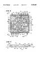
- FIG. 4is an exploded perspective view of a fluid control cassette that the fluid processing assembly shown in FIG. 2 incorporates, looking at the back side of the cassette body;
- FIG. 5is a perspective view of the front side of the cassette body shown in FIG. 4;
- FIG. 6is a plan view of the fluid circuits and interconnecting valve and sensing stations that the cassette body shown in FIG. 4 carries, looking at the back side of the cassette body;
- FIG. 7is a side view of the cassette body, taken generally along line 7--7 in FIG. 6;
- FIG. 8is an enlarged side section view of a representative valve station located within the cassette body shown in FIG. 4;
- FIG. 9is a plan view, taken on the back side of the cassette body, of the cassette shown in FIG. 4, with the tubing loops attached and ready for use;
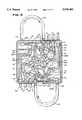
- FIG. 10is a diagrammatic view of a representative single needle fluid processing assembly usable in association with the centrifuge assembly shown in FIG. 1;
- FIG. 11is a side elevation view of the centrifuge assembly shown in FIG. 1, with the fluid processing assembly mounted for use, and with portions broken away to show the compartment that houses the associated centrifuge;
- FIG. 12is a perspective view of the compartment with the door opened to gain access to the centrifuge
- FIG. 13is a perspective view of the cassette holding stations located on the sloped front panel of the centrifuge assembly, just above the associated centrifuge shown in FIG. 11;
- FIG. 14is a perspective view of the pump and valve modules on one cassette holding station, with the splash guard lifted to show the associated valve assemblies and pressure sensors;
- FIG. 15is a perspective view of a cassette, carried within the tray, positioned for placement on the cassette holding station shown in FIG. 14;
- FIG. 16is enlarged perspective view of the one pump module with the pump tubing installed.
- FIG. 17is an elevated side section view showing the interior of an associated pump module.
- FIGS. 1 to 3show a centrifugal processing system 10 that embodies the features of the invention.
- the system 10can be used for processing various fluids.
- the system 10is particularly well suited for processing whole blood and other suspensions of biological cellular materials. Accordingly, the illustrated embodiment shows the system 10 used for this purpose.
- the system 10includes a centrifuge assembly 12 (see FIG. 1) and a fluid processing assembly 14 (see FIG. 2) used in association with the centrifuge assembly (see FIG. 3).
- the centrifuge assembly 12is intended to be a durable equipment item capable of long term, maintenance free use.
- the fluid processing assembly 14is intended to be a single use, disposable item loaded on the centrifuge assembly 12 at time of use (as FIG. 2 shows).
- the operatorremoves the fluid processing assembly 14 from the centrifuge assembly 12 upon the completing the procedure and discards it.
- FIG. 2shows an exploded view of the disposable processing assembly 14 that is usable in association with the centrifuge assembly.
- the assembly 14includes a processing chamber 16.
- the centrifuge assembly 12rotates the processing chamber 16 to centrifugally separate blood components.
- the construction of the processing chamber 16can vary.
- the processing assembly 14includes an array of flexible tubing that forms a fluid circuit 18.
- the fluid circuit 18conveys liquids to and from the processing chamber 16.
- the fluid circuit 18includes a number of containers 20.
- the containers 20fit on hangers on the centrifuge assembly 12 (see FIG. 2) to dispense and receive liquids during processing.
- the fluid circuit 18includes one or more in line cassettes 22.
- FIG. 2shows three cassettes, designated 22A; 22B; and 22C.
- the cassettes 22A/B/Ccentralize the valving and pumping functions to carry out the selected procedure.
- a portion of the fluid circuit 18 leading between the cassettes 22 and the processing chamber 16is bundled together to form an umbilicus 24.
- the umbilicus 24links the rotating parts of the processing assembly 14 (principally the processing chamber 16) with the nonrotating, stationary part of the processing assembly 14 (principally the cassettes 22 and containers 20).
- the umbilicus 24links the rotating and stationary parts of the processing assembly 14 without using rotating seals.
- the fluid circuit 18preconnects the processing chamber 16, the containers 20, and the cassettes 22.
- the assembly 14thereby forms an integral, sterile unit.
- the entire processing assembly 14is packaged for use within an organizer tray 26.
- the tray 26holds the processing chamber 16, the containers 20, the cassettes 22, and fluid circuit 18 in an orderly, compact package before use.
- the organizer tray 26mounts on the centrifuge assembly 12. After processing, the tray 26 receives the processing assembly 14 for disposal.
- FIGS. 4 to 9show the details of the preferred construction.
- the cassette 22includes an injection molded body 110 that is compartmentalized by an interior wall 534 to present a front side 112 (see FIG. 5) and a back side 114 (see FIG. 4).
- the front side 112is the side of the cassette 22 that, in use, faces toward the centrifuge assembly 12.
- a flexible diaphragm 116overlies the front side 112 of the cassette 22.
- a generally rigid back panel 118overlies the back side 114 of the cassette.
- the cassette 22, interior wall 534, and back panel 118are preferably made of a rigid medical grade plastic material.
- the diaphragm 116is preferably made of a flexible sheet of medical grade plastic.
- the diaphragm 116 and back panel 118are sealed about their peripheries to the peripheral edges of the front and back sides 112/114 of the cassette 22.
- FIGS. 4 and 5also best show, the front and back sides 112/114 of the cassette 22 contain preformed cavities.
- the cavitiesform an array of valve stations V N and an array of pressure sensing stations S N .
- the cavitiesform an array of channels or paths F N for conveying liquids.
- the valve stations V Ncommunicate with the liquid paths F N to interconnect them in a predetermined manner.
- the sensing stations S Nalso communicate with the liquid paths F N to sense pressures in selected regions.
- the cassette 22provides nineteen liquid paths F1 to F19, ten valve stations V1 to V10, and four sensing stations S1 to S4.
- valve and sensing stations V1/V10 and S1/S4resemble shallow wells open on the front cassette side 112 (see FIG. 5). As FIGS. 7 and 8 best show, upstanding edges 120 rise from the interior wall 534 and peripherally surround the stations V1/V10 and S1/S4.
- valve stations V1/V10are closed by the interior wall 534 on the back side 114 of the cassette 22, except that each valve station V N includes a pair of through holes or ports 122A and 122B in the interior wall 534 (see FIGS. 5 and 8).
- the ports 122A/Beach open into selected different liquid paths F N and F N , (see FIG. 8) on the back side 114 of the cassette 22.
- One of the ports 122Ais surrounded by a seating ring 124, while the other is not (see FIG. 8).
- the sensing stations S1/S4are likewise closed by the interior wall 534 on the back side 114 of the cassette 22, except that each sensing station V N includes three through holes or ports 126A/B/C in the interior wall 534 (see FIG. 5).
- the ports 126A/B/Copen into selected liquid paths F N on the back side 114 of the cassette 24. These ports 126 A/B/C channel liquid flow among the selected liquid paths F N through the associated sensing station.
- the flexible diaphragm 116 overlying the front side 112 of the cassette 22is sealed by ultrasonic welding to the upstanding peripheral edges 120 of the valve and sensing stations V1/V10 and S1/S4. This isolates the valve stations V1/V10 and sensing stations S1/S4 from each other and the rest of the system.
- the flexible diaphragm 116can be seated against the upstanding edges 120 by an external positive force applied by the centrifuge assembly 12 against the diaphragm 116 (as shown by the F1-arrows in FIG. 8).
- the positive force F1like the ultrasonic weld, peripherally seals the valve and sensing stations V1/V10 and S1/S10.
- the localized application of additional positive force upon the intermediate region of the diaphragm 116 overlying a valve station V1/V10serves to flex the diaphragm 116 into the valve station.
- the diaphragm 116seats against the ring 124 (as shown by phantom lines in FIG. 8) to seal the associated valve port 122A. This closes the valve station to liquid flow.
- the diameter and depth of the valve stationsare selected so that the flexing required to seat the diaphragm 116 does not exceed the elastic limits of the diaphragm material. In this way, the plastic memory of the plastic material alone is sufficient to unseat the diaphragm 116 in the absence of the force F2.
- the centrifuge assembly 12selectively applies localized positive force F2 to the diaphragm 116 for closing the valve ports 122A.
- upstanding edges 128rise from the interior wall 534 and peripherally surround the channels F1/F19, which are open on the back side 114 of the cassette 22.
- the liquid paths F1/F19are closed by the interior wall 534 on the front side 112 of the cassette 22, except for the ports 122A/B of the valve stations V1/V10 and the ports 126A/B/C of the sensing stations S1/S4 (see FIG. 6).
- the rigid panel 118 overlying the back side 114 of the cassette 22is sealed by ultrasonic welding to the upstanding peripheral edges 128, sealing the liquid paths F1/F19 from each other and the rest of the system 10.
- ten premolded tube connectors T1 to T10extend out along opposite side edges 130A/B of the cassette 22.
- the tube connectorsare arranged five on one side edge 130A (T1 to T5) and five on the other side edge 130B (T6 to T10).
- the other side edges 132A/B of the cassette 22are free of tube connectors. This ordered orientation of the tube connectors T1/T10 along only two side edges 130A/B of the cassette 22 provides a centralized, compact unit for mounted on the centrifuge assembly 12 (as FIG. 3 shows).
- the first through fifth tube connectors T1 to T5communicate with interior liquid paths F1 to F5, respectively.
- the sixth through tenth tube connectors T6 to T10communicate with interior liquid paths F6 to F10, respectively.
- These liquid paths F1 to F10constitute the primary liquid paths of the cassette 22, through which liquid enters or exits the cassette 22.
- the remaining interior liquid paths F11 to F19 of the cassette 22constitute branch paths that link the primary liquid paths F1 to F10 to each other through the valve stations V1 to V10 and sensing stations S1/S4.
- valve station V3controls liquid flow between primary liquid path F1 and branch fluid path F11.
- Valve station V2controls liquid flow between primary liquid path F2 and branch path F19.
- Valve station V1controls liquid flow between primary liquid path F3 and branch path F15.
- Sensing station S1links primary flow path F4 with branch paths F15 and F16.
- Sensing station S2links primary flow path F5 with branch paths F17 and F18.
- valve station V10controls liquid flow between primary liquid path F8 and branch fluid path F14.
- Valve station V9controls liquid flow between primary liquid path F9 and branch path F19.
- Valve station V8controls liquid flow between primary liquid path F10 and branch path F18.
- Sensing station S3links primary flow path F6 with branch paths F11 and F12.
- Sensing station S4links primary flow path F7 with branch paths F13 and F14.
- branch paths F16, F12, F17, and F13communicate with branch path F19 through valve stations V4, V5, V6, and V7, respectively.
- branch path F19serves as a central hub for conveying liquid between the primary fluid paths F1 to F5 on one side 130A of the cassette 22 and the primary fluid paths F6 to F10 on the other side 130B of the cassette 22.
- the branch paths F16 and F17feed the central hub F19 from the side 130A of the cassette 22, while the branch paths F12 and F13 feed the central hub F19 from the other side 130B of the cassette 22.
- an upstanding, generally elliptical ridge 532occupies the mid-portion of the central hub F19.
- the ridge 532helps to channel fluid within the hub F19 to the respective branch paths communicating with it.
- the ridge 532also reduces the overall fluid volume of the hub F19 to facilitate liquid conveyance within it.
- external tubing loop 134connects tube connector T4 with tube connector T5 on the side edge 130A.
- external tubing loop 136connections tube connector T7 with tube connector T6 on the other side edge 130B.
- the tube loops 134 and 136engage peristaltic pump rotors on the centrifuge assembly 12 to convey liquid into the cassette 22 and from the cassette 22.
- the tube connectors T1/T2 and T9/T10extend from their respective side edges 130A/B in a sloping direction toward the front side 112 of the cassette 22.
- the angle ⁇ that the sloped tube connector T1/T2 and T9/T10 make with the plane of the front side 112 of the cassette 22is about 10 degrees.
- the angled relationship of the tube connectors T1/T2 and T9/T10facilitates loading the associated tubing loops 134 and 136 on the peristaltic pump rotors.
- the remaining tube connectors T3 to T8 on the cassette 22are connected with the flexible tubing of the fluid circuit 18.
- FIG. 11shows a representative a single needle platelet collection system 28 (FIGS. 2 and 3 also show the single needle system 28 in association with the tray 26 and centrifuge assembly 12).
- the system 28includes the processing chamber 16 and containers 20 interconnected by the fluid circuit 18 carried by the organizer tray 26.
- the fluid circuit 18 for the system 28includes the three centralized pumping and valving cassettes, identified as 22A; 22B; and 22C.
- the umbilicus 24links the rotating and non-rotating components in each system 28 and 30.
- the processing chamber 16can be variously constructed. For example, it can be constructed like the double bag processing chambers shown in Cullis et al. U.S. Pat. No. 4,146,172.
- the processing chamber 16 in each system 28 and 30is formed as an elongated flexible tube made of a flexible, biocompatible plastic material such as plasticized medical grade polyvinyl chloride.
- the chamber 16includes a first stage compartment 34 and a second stage compartment 36.
- the first stage compartment 34receives whole blood (WB). When subjected to centrifugal forces, the first stage compartment 34 separates the WB into red blood cells (RBC) and platelet rich plasma (PRP).
- RBCred blood cells
- PRPplatelet rich plasma
- the second stage compartment 36receives PRP from the first stage compartment 32. When subjected to centrifugal forces, the second stage compartment 36 separates the PRP into concentrated platelets (PC) and platelet-poor plasma (PPP).
- PCconcentrated platelets
- PPPplatelet-poor plasma
- the fluid circuit 18includes five tubing branches 38/40/42/44/46 that communicate directly with the processing chamber 16. Three tubing branches 38/40/42 serve the first stage compartment 34. Two tubing branches 44/46 serve the second stage compartment 36.
- the tubing branch 40carries WB into the first stage compartment 34 for processing.
- the tubing branch 38carries separated PRP from the first stage compartment 34.
- the tubing branch third port 42carries separated RBC from the first stage compartment 34.
- the tubing branch 46carries PRP separated in the first compartment 34 into the second compartment 36 for further processing.
- the tubing branch 44carries separated PPP from the second stage compartment 36.
- the separated PCremains in the second stage compartment 36 for later resuspension and collection.
- the cassettes 22A/B/Cserve to segregate the flow paths of various categories of fluids and blood components from each other during processing.
- the cassette 22Aprincipally handles the flow of fluids containing red blood cells, either as WB or as RBC.
- the cassette 22Bprincipally handles the flow of cellular-free fluids, either as PPP or anticoagulant.
- the cassette 22Cprincipally handles the flow of fluids containing platelets, either as PRP or PC.
- the fluid circuit 18 for the single needle system 28includes a tubing branch 32 that carries a phlebotomy needle 48 for drawing WB from a donor.
- a tubing branch 33joins the tubing branch 32 and leads to the cassette 22A.
- a tubing branch 100carries an anticoagulant solution from a container 98 into the tubing branch cassette 22B (via a drip chamber 102). The anticoagulant flows from cassette 22B through tubing branch 92 for addition to the WB before processing.
- a tubing branch 56leads from the cassette 22A to convey anti-coagulated WB to a reservoir container 58.
- tubing branch 60leads from the cassette 22A to convey anti-coagulated WB into the umbilicus 24 via a drip chamber 64 and tubing branch 62.
- the umbilicus 24joins tubing branch 40, which carries the anti-coagulated WB into the first stage chamber 34 for separation into RBC and PRP.
- the tubing branch 42carries the separated RBC from the first stage chamber 34 through the umbilicus 24.
- the umbilicus 24joins the tubing branches 64, 66, and 68, which lead to a reservoir container 70 for RBC.
- a tubing branch 72joins tubing branch 68 to carry RBC from the reservoir container 70 to the cassette 22A.
- the tubing branch 74leads from the cassette 22A to carry RBC to the tubing branch 32, which leads to the phlebotomy needle 48.
- the cassette 22Athereby directs the flow of anti-coagulated WB from the donor into the first stage compartment 34.
- the cassette 22Aalso directs the flow of separated RBC from the first stage compartment 34 back to the donor.
- the single needle system 28collects through the cassette 22A a predetermined volume of anti-coagulated WB in the reservoir container 58 (through tubing branches 32/33/56), while conveying the rest of the anti-coagulated WB continuously to the first stage compartment 34 for separation (through tubing branches 32/33/60/62/40).
- the system 28also continuously collects the separated RBC in the reservoir container 70 (through tubing branches 42/64/66/68).
- the system 28continuously conveys through the cassette 22A anti-coagulated WB from the reservoir container 58 into the first stage compartment 34 for separation (through tubing branches 56/60/62/40). At the same time, the system 28 returns through the cassette 22A the RBC collected in the reservoir container 70 to the donor (through tubing branches 68/72/74/32) as well as those RBC being then separated in the first stage compartment 34 (via tubing branches 64 and 66, joining tubing branch 68).
- This two cycle sequence through the cassette 22Aassures that anti-coagulated WB is continuously conveyed to the first stage compartment for separation, either from the donor (during the draw cycle) or from the WB reservoir container 58 (during the return cycle).
- the tubing branch 86carries separated PRP from the first stage compartment 34 through the umbilicus 24 to the cassette 22C.
- tubing branch 80leads to the umbilicus 24, which joins tubing branch 46, which takes the PRP into the second stage compartment 36 for further separation into PPP and PC.
- the tubing branch 80carries an in line filter 82.
- the filter 82removes leukocytes from the PRP before it enters the second stage compartment 36 for separation.
- the tubing branch 44carries PPP from the second stage compartment 36 through the umbilicus 24 and to tubing branch 76, which leads to the cassette 22B.
- Tubing branch 88carries the PPP from the cassette 22B to a reservoir container 90.
- a portion of the PPP collected in the reservoir container 90is returned to the donor with the RBC during the return cycle.
- This portion of PPPis conveyed from the reservoir container 90 through tubing branch 66 via the cassette 22B to tubing branch 72, which joins the tubing branch 33 via cassette 22A.
- PPP then being separated in the second stage compartment 36is returned to the donor through tubing branches 85 and 76 to the tubing branch 66 via the cassette 22B.
- Another portion of the PPP collected in the reservoir container 90is used to resuspend PC in the second stage compartment 36 after separation ends.
- This portion of PPPis conveyed from the reservoir container 90 through tubing branch 88 via the cassette 22B, back through tubing branch 76, the umbilicus 24, and tubing branch 44 into the second stage compartment 36.
- the PPPresuspends PC accumulated in the compartment 36.
- the tubing branch 46conveys resuspended PC from the compartment 36, through the umbilicus 24 to tubing branch 86, which joins the cassette 22C.
- Tubing branch 94conveys resuspended PC from the cassette 22C to collection containers 96.
- PPPwhich carries most of the anticoagulant added during processing
- the PPPcan serve as an anti-coagulated "keep open” fluid, to keep the phlebotomy needle 48 open during lulls in processing.
- the PPPcan also be used as a "final flush” fluid, to purge the tubing branches after processing.
- the PPP remaining in the reservoir container 90 after processingcan be stored for therapeutic purposes.
- Container 50holds a saline priming solution, which is used to purge air from the system 28 before processing.
- Tubing branch 52carries the saline from the container 50 (via the drip chamber 54) to cassette 22A.
- the salineis conveyed from the cassette 22A into the processing chamber 16 via tubing branches 60 and 62, and from there to the rest of the system 28 along the tubing branches already described.
- the centrifuge assembly 12(see FIGS. 1 and 11) carries the operating elements essential for a diverse number of blood processing procedures under the direction of an onboard controller.
- the centrifuge assembly 12is housed with a wheeled cabinet 228, which the user can easily move from place to place. It should be appreciated that, due to its compact form, the centrifuge assembly 12 also could be made and operated as a tabletop unit.
- the centrifuge assembly 12includes a centrifuge 230 (see FIG. 11 mounted for rotation inside a compartment 232 of the cabinet 228.
- the compartment 232has a fold-open door 234, which the user opens (see FIG. 12) to gain access to the centrifuge 230 to load and unload the processing chamber 16 of the fluid circuit 18.
- centrifuge 230Specific details of the construction of the centrifuge 230 are not essential to an understanding of the invention and can be found in copending U.S. patent application Ser. No. 08/176,425, filed Dec. 22, 1993 and entitled "Centrifuge with Pivot Out, Easy Load Processing Chamber,” which is incorporated herein by reference.
- the centrifuge assembly 12also includes three cassette control stations 236 A/B/C (see FIG. 13), one for each cassette 22 A/B/C.
- the cassette control stations 236 A/B/Care located side by side on a sloped outside panel 238 of the cabinet 228.
- the outside panel 238also carries the shut-off clamps 240, hemolysis sensor 244A, and air detector 244B associated with the centrifuge assembly 12 (see FIG. 13).
- the centrifuge assembly 12includes a processing controller 246.
- the controller 246governs the operation of the centrifuge assembly 12.
- the processing controller 246preferably includes an integrated input/output terminal 248 (also seen on FIG. 1), which receives and display information relating to the processing procedure.
- each control station 236A/B/Cholds one cassettes 22A/B/C (see FIG. 15).
- the control stationare all constructed alike, so the details of only one station 236A will be provided. In use, the station holds the cassette 22A.
- the control station 236A(see FIGS. 14 and 15) includes a cassette holder 250.
- the holder 250receives and grips the cassette 22A along two opposed sides 132A and B in the desired operating position on the control station 236A (as FIG. 3 shows).
- the holder 250urges the diaphragm 116 on the front cassette side 112 into intimate contact with a valve module 252 on the control station 236 A.
- the valve module 252acts in concert with the valve stations V1/V10 and sensing stations S1/S2/S3/S4 in the cassette 22A.
- the control stationalso includes a peristaltic pump module 254.
- a peristaltic pump module 254When the cassette 22A is gripped by the holder 250, the tubing loops 134 and 136 make operative engagement with the pump module 254.
- the controller 246governs the operation of holder 250 on each control station 236A/B/C to grip the cassettes 22A/B/C upon receipt of a preselected command signal. The controller 246 then proceeds to govern the operation of the valve module 252 and pump module 254 on each control station 236A/B/C to convey liquids through the cassettes 22A/B/C to achieve the processing objectives of the system 10.
- valve module 252 on each control station 236A/B/Ccontains an array of valve assemblies 286 located between the gripping elements 256.
- the force F1 that the gripping elements 256 exert(see FIG. 8), hold the diaphragm 116 of the cassette 22A in intimate contact against the valve assemblies 286.
- a thin elastomeric membrane 288is stretched across the valve assembly 286, serving as a splash guard.
- the splash guard membrane 288keeps liquids and dust out of the valve assembly 286.
- the splash guard membrane 288can be periodically wiped clean when cassettes are exchanged.
- the valve assembly 286includes ten valve actuating pistons PA1 to PA10 and four pressure sensing transducers PS1 to PS4.
- the valve actuators PA1 to PA10 and the pressure sensing transducers PS1 to PS4are mutually arranged to form a mirror image of the valve stations V1 to V10 and sensing stations S1 to S4 on the front side 112 of the cassette 22A.
- valve actuators PA1 to PA10align with the cassette valve stations V1 to V10.
- the pressure sensing transducers PS1 to PS4mutually align with the cassette sensing stations S1 to S4.
- Each valve actuator PA1 to PA10comprises an electrically actuated solenoid piston 290.
- Each piston 290is independently movable between an extended position and a retracted position.
- the piston 290When in its extended position, the piston 290 presses against the region of the diaphragm 116 that overlies the associated valve station V1/V10 (exerting the force F2 shown in FIG. 8). In this position, the piston 290 flexes the diaphragm 116 into the associated valve station to seat the diaphragm 116 against the ring 124, and thereby seal the associated valve port 122A. This closes the valve station to liquid flow.
- the piston 290When in its retracted position, the piston 290 does not apply force against the diaphragm 116. As before described, the plastic memory of the diaphragm 116 unseats it from the valve ring 124 (as FIG. 8 shows), and thereby opens the valve station to liquid flow.
- the pressure sensing transducers PS1 to PS4sense liquid pressures in the sensing stations S1 to S4. The sensed pressures are transmitted to the controller 246 as part of its overall system monitoring function.
- each cassette pumping module 254includes a pair of peristaltic rotor assemblies 292.
- the rotor assemblies 292face each other at opposite ends of the valve assembly 286.
- a rear wall 294extends about half way around the back side of each rotor assembly 292 (see FIGS. 14 and 15).
- the space between the rear wall 294 and the rotor assembly 292forms a pump race 296.
- the tubing loops 134 and 136extend into the pump race 296 (as FIG. 16 shows).
- the tube connectors T4/T5 and T6/T7 from which the loops 134 and 136 extendslope in the direction the pump rotor assemblies 292 to orient the loops 134 and 136 relative to the race 296 while loading the cassette 22A onto the station 236A.
- each rotor assembly 292includes a rotor 298 that carries a pair of diametrically spaced rollers 300.
- the rollers 300in succession compress the associated tubing loop 134/136 against the rear wall 294 of the pump race 296 (as FIG. 43 shows). This well known peristaltic pumping action urges fluid through the associated loop 134/136.
- a small brushless direct current motor 326drives each peristaltic pump rotor 298.
- a gear assembly 328couples the motor 326 to the associated rotor 298.
- each pump rotor assembly 292 just describedmeasures about 2.7 inches in diameter and about 6.5 inches in overall length, including the motor 326.
- the pump rotor assembly 292needs to operate at both relatively high flow rates (between 10 ml/min and 170 ml/min) and relatively low flow rates (i.e., less than 10 ml/min).
- the high flow ratesare needed, for example, to supply WB to the processing chamber 26 (typically at about 50 ml/min) and to circulate saline and/or PPP to purge the tubing branches after processing (typically at about 100 ml/min, or higher).
- Relatively low flow ratesare needed, for example, when conveying anticoagulant through tubing branch 100 (in the single needle system shown in FIG. 10). This is because a wide range of donor reactions can occur if too much anticoagulant is added, as this anticoagulant is ultimately returned to the donor with the reinfused plasma.
- Relatively low flow ratesare also needed, for example, when recirculating a portion of the PRP from the first stage compartment 34 back to the WB entering the compartment (through tubing branch 34 to the drip chamber 64 in the single needle system shown in FIG. 10).
- the controller 246operates the pump rotor assembly 292 in two modes.
- the firstis a continuous mode, in which the pump rotor rotates continuously at an angular velocity selected to achieve the desired flow rate.
- the minimum continuous flow rate that the pump rotor assembly 292 maintains in the first modeis about 10 ml/min.
- the maximum continuous flow ratecan be as high as about 170 ml/min.
- the controller 246When flow rates below the minimum continuous flow rate are required, the controller 246 operates the pump rotor assembly 292 in an intermittent, or pulse, mode. In the pulse mode, the controller 246 controls power to the brushless motor 326 to achieve desired first angular velocity for a first selected time period, followed in succession by at least one additional time period during which power is controlled to achieve a second angular velocity different than the first angular velocity.
- the selected second angular velocitycan be greater than or less than the first angular velocity.
- the second angular velocitycan also be in an opposite direction than the first angular velocity, if desired to pulse fluid back and forth.
- the second angular velocityis at or near zero, so that rotation of the pump rotor 298 actually or essentially stops for the second time period.
- the controller 246successive controls power to achieve a third angular velocity that is above zero and is preferably equal to the first angular velocity, for a third time period, followed in succession by a fourth time period during which rotation of the rotor 298 actually or essentially stops, and so on.
- the controller 292achieves intermittent periods of rotation of the rotor 298, spaced by intervals in which the rotor 298 stops rotating.
- the controller 292can operate the pump rotor assembly 292 in a range of low flow rates well below the minimum continuous flow rate.
- the effective flow rate R EFF of the pump rotor assembly 292 (in ml/min)when operated in the pulse modecan be expressed as follows: ##EQU1## where: T ON is the time interval (in seconds) that the rotor 298 rotates,
- T OFFis the time interval (in seconds) that the rotor 298 does not rotate
- RPMis the rotor speed during rotation (in revolutions per minute)
- kis the pump flow constant of the particular pump rotor assembly (in ml/revolution).
- the controller 246sets a desired RPM and turns the pump motor 326 on and off in sequential pulses timed to achieve the desired flow rate. Typically, during each period in which the rotor 298 is turned on, the rotor 298 rotates less than one complete revolution. By pulsing in this manner, the controller 246 achieves flow rates that are well below the minimum continuous flow rate of the pump rotor assembly 292.
- the controller 292sets the desired RPM to achieve the minimum continuous flow rate (which, in the illustrated embodiment is 10 ml/min).
- the timing of the pulsesfalls within the range of between about 0.3 second to 2.7 seconds.
- the controller 246provides effective flow rates of between about 1.0 and 9 ml/min.
- the controller 246includes a look up table in non-volatile memory that correlates, based upon empirical data that takes into account the particular pump flow constant and the selected RPM, the desired pumping rate with pulse on and pulse off time periods.
- a representative look up table, based upon a minimum continuous RPM of 10 ml/min,is shown below:
- the just described implementationis best achieved when the pump rotor assembly 292 has a relatively high torque.
- the rotor 298achieves the desired angular velocity in a short period of time when power is applied, while at the same time stopping rotation in a short period of time when power is interrupted.
- the controllercould apply continuous power to a direct current stepper motor while changing the commutation patterns to electrically lock and unlock the rotor.
- the controllercould employ a mechanical brake in combination with the interruption of power to quickly stop rotation of the rotor when desired.
Landscapes
- Health & Medical Sciences (AREA)
- Heart & Thoracic Surgery (AREA)
- Vascular Medicine (AREA)
- Engineering & Computer Science (AREA)
- Life Sciences & Earth Sciences (AREA)
- Veterinary Medicine (AREA)
- Biomedical Technology (AREA)
- Hematology (AREA)
- Anesthesiology (AREA)
- Animal Behavior & Ethology (AREA)
- General Health & Medical Sciences (AREA)
- Public Health (AREA)
- Cardiology (AREA)
- Urology & Nephrology (AREA)
- Emergency Medicine (AREA)
- Mechanical Engineering (AREA)
- General Engineering & Computer Science (AREA)
- External Artificial Organs (AREA)
- Reciprocating Pumps (AREA)
Abstract
Description
______________________________________ Command R.sub.EFF T.sub.ON T.sub.OFF (in ml/min) (in secs.) (in secs.) ______________________________________ 1 0.3 2.7 2 0.3 1.2 3 0.3 0.7 4 0.4 0.6 5 0.5 0.5 6 0.6 0.4 7 0.7 0.3 8 1.2 0.3 9 2.7 0.3 ______________________________________
Claims (1)
Priority Applications (10)
| Application Number | Priority Date | Filing Date | Title |
|---|---|---|---|
| US08/269,933US5538405A (en) | 1994-07-01 | 1994-07-01 | Peristaltic pulse pumping systems and methods |
| AU14495/95AAU679319B2 (en) | 1994-07-01 | 1995-01-09 | Peristaltic pulse pumping systems and methods |
| EP95906180AEP0719386B1 (en) | 1994-07-01 | 1995-01-09 | Peristaltic pulse pumping systems |
| DE69512504TDE69512504T2 (en) | 1994-07-01 | 1995-01-09 | PUMP SYSTEMS WITH PERISTALTIC PUMPS |
| BR9506009ABR9506009A (en) | 1994-07-01 | 1995-01-09 | Peristaltic pumping apparatus blood processing system and process to separate blood in a system |
| CA002169257ACA2169257C (en) | 1994-07-01 | 1995-01-09 | Peristaltic pulse pumping systems and methods |
| MX9600798AMX9600798A (en) | 1994-07-01 | 1995-01-09 | Peristaltic pulse pumping systems and methods. |
| JP8503855AJPH09502783A (en) | 1994-07-01 | 1995-01-09 | Peristaltic pulse pumping system and method |
| PCT/US1995/000273WO1996001371A1 (en) | 1994-07-01 | 1995-01-09 | Peristaltic pulse pumping systems and methods |
| SG1996003933ASG48943A1 (en) | 1994-07-01 | 1995-01-09 | Peristaltic pulse pumping system and methods |
Applications Claiming Priority (1)
| Application Number | Priority Date | Filing Date | Title |
|---|---|---|---|
| US08/269,933US5538405A (en) | 1994-07-01 | 1994-07-01 | Peristaltic pulse pumping systems and methods |
Publications (1)
| Publication Number | Publication Date |
|---|---|
| US5538405Atrue US5538405A (en) | 1996-07-23 |
Family
ID=23029219
Family Applications (1)
| Application Number | Title | Priority Date | Filing Date |
|---|---|---|---|
| US08/269,933Expired - LifetimeUS5538405A (en) | 1994-07-01 | 1994-07-01 | Peristaltic pulse pumping systems and methods |
Country Status (10)
| Country | Link |
|---|---|
| US (1) | US5538405A (en) |
| EP (1) | EP0719386B1 (en) |
| JP (1) | JPH09502783A (en) |
| AU (1) | AU679319B2 (en) |
| BR (1) | BR9506009A (en) |
| CA (1) | CA2169257C (en) |
| DE (1) | DE69512504T2 (en) |
| MX (1) | MX9600798A (en) |
| SG (1) | SG48943A1 (en) |
| WO (1) | WO1996001371A1 (en) |
Cited By (57)
| Publication number | Priority date | Publication date | Assignee | Title |
|---|---|---|---|---|
| US5947689A (en)* | 1997-05-07 | 1999-09-07 | Scilog, Inc. | Automated, quantitative, system for filtration of liquids having a pump controller |
| US5993420A (en) | 1995-03-06 | 1999-11-30 | Sabratek Corporation | Cassette for an infusion pump |
| US6234773B1 (en) | 1994-12-06 | 2001-05-22 | B-Braun Medical, Inc. | Linear peristaltic pump with reshaping fingers interdigitated with pumping elements |
| US6393338B1 (en)* | 2000-03-17 | 2002-05-21 | Tadeusz Kemnitz | Apparatus and control method for accurate rotary peristaltic pump filling |
| US6527745B1 (en) | 1999-10-06 | 2003-03-04 | Nidek Co., Ltd. | Irrigation-aspiration apparatus |
| US6537244B2 (en) | 1999-01-19 | 2003-03-25 | Assistive Technology Products, Inc. | Methods and apparatus for delivering fluids |
| US20030181305A1 (en)* | 2002-03-04 | 2003-09-25 | Briggs Dennis A. | Method and apparatus for the continuous separation of biological fluids into components |
| US6636010B1 (en) | 2001-10-01 | 2003-10-21 | Zevex, Inc. | Precision dosage apparatus, system and method |
| US20030220599A1 (en)* | 2002-05-24 | 2003-11-27 | Lundtveit Loren M. | One-piece tip protector and organizer |
| WO2003106266A1 (en)* | 2002-06-14 | 2003-12-24 | Scilog, Inc. | Single-use manifold for automated, aseptic transfer of soulutions in bioprocessing applications |
| US20040124157A1 (en)* | 2002-03-04 | 2004-07-01 | Dennis Briggs | Apparatus for the continuous separation of biological fluids into components and method of using same |
| WO2004083640A3 (en)* | 2003-03-18 | 2005-01-06 | Jms Co Ltd | Roller pump |
| US20050101937A1 (en)* | 2003-11-06 | 2005-05-12 | Nova-Tech Engineering, Inc. | Apparatus and method for nasal delivery of compositions to birds |
| EP1485617A4 (en)* | 2002-02-21 | 2006-03-08 | Terumo Cardiovascular Sys | Dynamic brake with backlash control for peristaltic pump |
| US20060140799A1 (en)* | 2003-03-13 | 2006-06-29 | Chf Solutions Inc. | Self-loading peristaltic pump for extracorporeal blood circuit |
| US20070213654A1 (en)* | 2002-05-24 | 2007-09-13 | Baxter International Inc. | Method of making a peritoneal dialysis therapy machine |
| US20080058727A1 (en)* | 2006-07-17 | 2008-03-06 | Domash David M | Connector to cassette interface system |
| US20080058712A1 (en)* | 2006-08-31 | 2008-03-06 | Plahey Kulwinder S | Peritoneal dialysis machine with dual voltage heater circuit and method of operation |
| US7476209B2 (en) | 2004-12-21 | 2009-01-13 | Therakos, Inc. | Method and apparatus for collecting a blood component and performing a photopheresis treatment |
| US7479123B2 (en) | 2002-03-04 | 2009-01-20 | Therakos, Inc. | Method for collecting a desired blood component and performing a photopheresis treatment |
| US20090087328A1 (en)* | 2005-11-28 | 2009-04-02 | Faulkner Donald G | Pulse generating device |
| US7934912B2 (en) | 2007-09-27 | 2011-05-03 | Curlin Medical Inc | Peristaltic pump assembly with cassette and mounting pin arrangement |
| US7935074B2 (en) | 2005-02-28 | 2011-05-03 | Fresenius Medical Care Holdings, Inc. | Cassette system for peritoneal dialysis machine |
| US20110186143A1 (en)* | 2010-02-03 | 2011-08-04 | Seiko Epson Corporation | Fluid transporter |
| US8062008B2 (en) | 2007-09-27 | 2011-11-22 | Curlin Medical Inc. | Peristaltic pump and removable cassette therefor |
| US8083503B2 (en) | 2007-09-27 | 2011-12-27 | Curlin Medical Inc. | Peristaltic pump assembly and regulator therefor |
| WO2012027312A1 (en) | 2010-08-24 | 2012-03-01 | Fenwal, Inc. | Methods and systems for anticoagulating blood |
| US8142653B2 (en) | 2002-06-04 | 2012-03-27 | Fresenius Medical Care Deutschland Gmbh | Medical fluid cassettes and related systems |
| US8192401B2 (en) | 2009-03-20 | 2012-06-05 | Fresenius Medical Care Holdings, Inc. | Medical fluid pump systems and related components and methods |
| USD668675S1 (en)* | 2010-09-17 | 2012-10-09 | Molon Motor And Coil Corporation | Peristaltic pump rotor |
| USD672455S1 (en) | 2010-10-01 | 2012-12-11 | Zevex, Inc. | Fluid delivery cassette |
| US8539672B2 (en) | 2010-10-01 | 2013-09-24 | Zevex, Inc. | Method for improving accuracy in a peristaltic pump system based on tubing material properties |
| US8692167B2 (en) | 2010-12-09 | 2014-04-08 | Fresenius Medical Care Deutschland Gmbh | Medical device heaters and methods |
| US8720913B2 (en) | 2009-08-11 | 2014-05-13 | Fresenius Medical Care Holdings, Inc. | Portable peritoneal dialysis carts and related systems |
| US8752436B2 (en) | 2010-10-01 | 2014-06-17 | Zevex, Inc. | Pressure sensor seal and method of use |
| EP1517717B1 (en)* | 2002-05-24 | 2014-11-26 | Baxter International Inc. | Hardware systems, methods and apparatuses for an automated dialysis machine |
| US8911414B2 (en) | 2010-10-01 | 2014-12-16 | Zevex, Inc. | Anti free-flow occluder and priming actuator pad |
| US8932032B2 (en) | 2005-07-13 | 2015-01-13 | Fresenius Medical Care Holdings, Inc. | Diaphragm pump and pumping systems |
| US9004886B2 (en) | 2010-10-01 | 2015-04-14 | Zevex, Inc. | Pressure monitoring system for infusion pumps |
| US9011114B2 (en) | 2011-03-09 | 2015-04-21 | Fresenius Medical Care Holdings, Inc. | Medical fluid delivery sets and related systems and methods |
| US9180240B2 (en) | 2011-04-21 | 2015-11-10 | Fresenius Medical Care Holdings, Inc. | Medical fluid pumping systems and related devices and methods |
| US9186449B2 (en) | 2011-11-01 | 2015-11-17 | Fresenius Medical Care Holdings, Inc. | Dialysis machine support assemblies and related systems and methods |
| US9421314B2 (en) | 2009-07-15 | 2016-08-23 | Fresenius Medical Care Holdings, Inc. | Medical fluid cassettes and related systems and methods |
| USD767118S1 (en)* | 2015-05-13 | 2016-09-20 | MAQUET CARDIOPULMONARY GmbH | Roller pump |
| USD768289S1 (en)* | 2015-05-13 | 2016-10-04 | MAQUET CARDIOPULMONARY GmbH | Dual roller pump assembly |
| USD768290S1 (en)* | 2015-05-13 | 2016-10-04 | MAQUET CARDIOPULMONARY GmbH | Roller pump |
| USD768847S1 (en)* | 2015-05-13 | 2016-10-11 | MAQUET CARDIOPULMONARY GmbH | Roller pump |
| US9500188B2 (en) | 2012-06-11 | 2016-11-22 | Fresenius Medical Care Holdings, Inc. | Medical fluid cassettes and related systems and methods |
| US9561323B2 (en) | 2013-03-14 | 2017-02-07 | Fresenius Medical Care Holdings, Inc. | Medical fluid cassette leak detection methods and devices |
| US9610392B2 (en) | 2012-06-08 | 2017-04-04 | Fresenius Medical Care Holdings, Inc. | Medical fluid cassettes and related systems and methods |
| US9694125B2 (en) | 2010-12-20 | 2017-07-04 | Fresenius Medical Care Holdings, Inc. | Medical fluid cassettes and related systems and methods |
| US9700844B2 (en) | 2002-06-14 | 2017-07-11 | Parker-Hannifin Corporation | Single-use manifolds for automated, aseptic handling of solutions in bioprocessing applications |
| USD801521S1 (en)* | 2015-05-13 | 2017-10-31 | MAQUET CARDIOPULMONARY GmbH | Roller pump |
| US10117985B2 (en) | 2013-08-21 | 2018-11-06 | Fresenius Medical Care Holdings, Inc. | Determining a volume of medical fluid pumped into or out of a medical fluid cassette |
| WO2020139693A1 (en)* | 2018-12-28 | 2020-07-02 | Avent, Inc. | Peristaltic pump assembly and system |
| USRE49221E1 (en) | 2002-06-14 | 2022-09-27 | Parker Intangibles, Llc | Single-use manifolds for automated, aseptic handling of solutions in bioprocessing applications |
| US11668295B2 (en) | 2018-12-28 | 2023-06-06 | Avent, Inc. | Pump head for a peristaltic pump |
Families Citing this family (6)
| Publication number | Priority date | Publication date | Assignee | Title |
|---|---|---|---|---|
| US6554789B1 (en)* | 1997-02-14 | 2003-04-29 | Nxstage Medical, Inc. | Layered fluid circuit assemblies and methods for making them |
| CN100344874C (en)* | 2003-01-28 | 2007-10-24 | 清华大学 | Fluid transmission method and minisize peristaltic pump for realizing the same |
| US8034018B2 (en)* | 2007-12-20 | 2011-10-11 | Bausch & Lomb Incorporated | Surgical system having means for stopping vacuum pump |
| IT1392231B1 (en)* | 2008-10-09 | 2012-02-22 | Ragazzini S R L | MANAGEMENT METHOD |
| ITVR20120034A1 (en)* | 2012-03-02 | 2013-09-03 | Tecres Spa | UNIVERSAL INFUSER DEVICE FOR MEDICINAL AND SIMILAR LIQUIDS, AND METHOD FOR CONTROL OF MEDICINAL AND SIMILAR DISTRIBUTION DISPOSAL. |
| CN112842233A (en)* | 2015-04-03 | 2021-05-28 | 席勒斯科技有限公司 | Surgical fluid management system |
Citations (20)
| Publication number | Priority date | Publication date | Assignee | Title |
|---|---|---|---|---|
| US3938909A (en)* | 1973-04-06 | 1976-02-17 | Willock Charles B | Single needle alternating flow blood pump system |
| US4108575A (en)* | 1975-08-09 | 1978-08-22 | Dr. Eduard Fresenius Chemisch-Pharmazeutische Industrie K.G. | Obtaining desired flow rate from roller pump despite varying the hose means |
| US4210409A (en)* | 1978-05-19 | 1980-07-01 | Child Laboratories Inc. | Solenoid operating pump |
| US4221543A (en)* | 1977-11-07 | 1980-09-09 | Renal Systems, Inc. | Bloom pump system |
| US4365728A (en)* | 1978-03-13 | 1982-12-28 | Pilot Man-Nen-Hitsu Kabushiki Kaisha | Liquid discharge apparatus |
| US4468219A (en)* | 1983-12-20 | 1984-08-28 | International Business Machines Corporation | Pump flow rate compensation system |
| US4492531A (en)* | 1982-04-30 | 1985-01-08 | Kuraray Co., Ltd. | Apparatus for producing a controlled pulsed liquid flow |
| US4496342A (en)* | 1981-03-20 | 1985-01-29 | Surgical Design Corporation | Surge prevention system for an ophthalmic instrument |
| US4498850A (en)* | 1980-04-28 | 1985-02-12 | Gena Perlov | Method and device for fluid transfer |
| US4549860A (en)* | 1983-04-04 | 1985-10-29 | Yakich Sam S | Blood pump improvements |
| US4662829A (en)* | 1984-01-05 | 1987-05-05 | C. R. Bard, Inc. | Pulsatile pump |
| US4735726A (en)* | 1981-07-22 | 1988-04-05 | E. I. Du Pont De Nemours And Company | Plasmapheresis by reciprocatory pulsatile filtration |
| US4755168A (en)* | 1987-01-27 | 1988-07-05 | Pat Romanelli | Medical drainage pump with irrigation |
| US4910682A (en)* | 1984-12-14 | 1990-03-20 | Cole-Parmer Instrument Company | Method of calibrating and determining the rotational and fluid delivery velocities of a peristaltic fluid pump |
| US4969808A (en)* | 1988-11-24 | 1990-11-13 | Oval Engineering Co., Ltd. | Elastic tubing pump |
| US5024347A (en)* | 1988-06-08 | 1991-06-18 | Baldwin Brian E | Adjustably controllable accuracy-enhancing pump arrangement and method |
| US5083908A (en)* | 1989-03-24 | 1992-01-28 | Asulab S.A. | Miniature peristaltic pump |
| US5098261A (en)* | 1990-05-04 | 1992-03-24 | Brandel Corporation | Peristaltic pump and method for adjustable flow regulation |
| US5125891A (en)* | 1987-04-27 | 1992-06-30 | Site Microsurgical Systems, Inc. | Disposable vacuum/peristaltic pump cassette system |
| US5195960A (en)* | 1987-04-27 | 1993-03-23 | Site Microsurgical Systems, Inc. | Disposable vacuum/peristaltic pump cassette system |
- 1994
- 1994-07-01USUS08/269,933patent/US5538405A/ennot_activeExpired - Lifetime
- 1995
- 1995-01-09JPJP8503855Apatent/JPH09502783A/enactivePending
- 1995-01-09EPEP95906180Apatent/EP0719386B1/ennot_activeExpired - Lifetime
- 1995-01-09CACA002169257Apatent/CA2169257C/ennot_activeExpired - Lifetime
- 1995-01-09DEDE69512504Tpatent/DE69512504T2/ennot_activeExpired - Lifetime
- 1995-01-09BRBR9506009Apatent/BR9506009A/ennot_activeIP Right Cessation
- 1995-01-09MXMX9600798Apatent/MX9600798A/enunknown
- 1995-01-09WOPCT/US1995/000273patent/WO1996001371A1/enactiveIP Right Grant
- 1995-01-09SGSG1996003933Apatent/SG48943A1/enunknown
- 1995-01-09AUAU14495/95Apatent/AU679319B2/ennot_activeExpired
Patent Citations (22)
| Publication number | Priority date | Publication date | Assignee | Title |
|---|---|---|---|---|
| US3938909A (en)* | 1973-04-06 | 1976-02-17 | Willock Charles B | Single needle alternating flow blood pump system |
| US4108575A (en)* | 1975-08-09 | 1978-08-22 | Dr. Eduard Fresenius Chemisch-Pharmazeutische Industrie K.G. | Obtaining desired flow rate from roller pump despite varying the hose means |
| US4221543A (en)* | 1977-11-07 | 1980-09-09 | Renal Systems, Inc. | Bloom pump system |
| US4365728A (en)* | 1978-03-13 | 1982-12-28 | Pilot Man-Nen-Hitsu Kabushiki Kaisha | Liquid discharge apparatus |
| US4210409A (en)* | 1978-05-19 | 1980-07-01 | Child Laboratories Inc. | Solenoid operating pump |
| US4498850A (en)* | 1980-04-28 | 1985-02-12 | Gena Perlov | Method and device for fluid transfer |
| US4697989A (en)* | 1980-04-28 | 1987-10-06 | Gena Perlov | Electrodynamic peristaltic fluid transfer device and method |
| US4496342A (en)* | 1981-03-20 | 1985-01-29 | Surgical Design Corporation | Surge prevention system for an ophthalmic instrument |
| US4735726A (en)* | 1981-07-22 | 1988-04-05 | E. I. Du Pont De Nemours And Company | Plasmapheresis by reciprocatory pulsatile filtration |
| US4492531A (en)* | 1982-04-30 | 1985-01-08 | Kuraray Co., Ltd. | Apparatus for producing a controlled pulsed liquid flow |
| US4549860A (en)* | 1983-04-04 | 1985-10-29 | Yakich Sam S | Blood pump improvements |
| US4468219A (en)* | 1983-12-20 | 1984-08-28 | International Business Machines Corporation | Pump flow rate compensation system |
| US4662829A (en)* | 1984-01-05 | 1987-05-05 | C. R. Bard, Inc. | Pulsatile pump |
| US4910682A (en)* | 1984-12-14 | 1990-03-20 | Cole-Parmer Instrument Company | Method of calibrating and determining the rotational and fluid delivery velocities of a peristaltic fluid pump |
| US4755168A (en)* | 1987-01-27 | 1988-07-05 | Pat Romanelli | Medical drainage pump with irrigation |
| US5125891A (en)* | 1987-04-27 | 1992-06-30 | Site Microsurgical Systems, Inc. | Disposable vacuum/peristaltic pump cassette system |
| US5195960A (en)* | 1987-04-27 | 1993-03-23 | Site Microsurgical Systems, Inc. | Disposable vacuum/peristaltic pump cassette system |
| US5024347A (en)* | 1988-06-08 | 1991-06-18 | Baldwin Brian E | Adjustably controllable accuracy-enhancing pump arrangement and method |
| US5024347B1 (en)* | 1988-06-08 | 1995-05-23 | Baxa Corp | Adjustably controllable accuracy-enhancing pump arrangement and method |
| US4969808A (en)* | 1988-11-24 | 1990-11-13 | Oval Engineering Co., Ltd. | Elastic tubing pump |
| US5083908A (en)* | 1989-03-24 | 1992-01-28 | Asulab S.A. | Miniature peristaltic pump |
| US5098261A (en)* | 1990-05-04 | 1992-03-24 | Brandel Corporation | Peristaltic pump and method for adjustable flow regulation |
Cited By (105)
| Publication number | Priority date | Publication date | Assignee | Title |
|---|---|---|---|---|
| US6234773B1 (en) | 1994-12-06 | 2001-05-22 | B-Braun Medical, Inc. | Linear peristaltic pump with reshaping fingers interdigitated with pumping elements |
| US5993420A (en) | 1995-03-06 | 1999-11-30 | Sabratek Corporation | Cassette for an infusion pump |
| US5947689A (en)* | 1997-05-07 | 1999-09-07 | Scilog, Inc. | Automated, quantitative, system for filtration of liquids having a pump controller |
| US6752779B2 (en) | 1999-01-19 | 2004-06-22 | Assistive Technology Products, Inc. | Methods and apparatus for delivering fluids |
| US6537244B2 (en) | 1999-01-19 | 2003-03-25 | Assistive Technology Products, Inc. | Methods and apparatus for delivering fluids |
| US6527745B1 (en) | 1999-10-06 | 2003-03-04 | Nidek Co., Ltd. | Irrigation-aspiration apparatus |
| US6393338B1 (en)* | 2000-03-17 | 2002-05-21 | Tadeusz Kemnitz | Apparatus and control method for accurate rotary peristaltic pump filling |
| US6636010B1 (en) | 2001-10-01 | 2003-10-21 | Zevex, Inc. | Precision dosage apparatus, system and method |
| EP1485617A4 (en)* | 2002-02-21 | 2006-03-08 | Terumo Cardiovascular Sys | Dynamic brake with backlash control for peristaltic pump |
| US10556055B2 (en) | 2002-03-04 | 2020-02-11 | Mallinckrodt Hospital Products IP Limited | Method for collecting a desired blood component and performing a photopheresis treatment |
| US7186230B2 (en) | 2002-03-04 | 2007-03-06 | Therakos, Inc | Method and apparatus for the continuous separation of biological fluids into components |
| US20040124157A1 (en)* | 2002-03-04 | 2004-07-01 | Dennis Briggs | Apparatus for the continuous separation of biological fluids into components and method of using same |
| US7914477B2 (en) | 2002-03-04 | 2011-03-29 | Therakos, Inc. | Apparatus for the continuous separation of biological fluids into components and method of using same |
| US7850634B2 (en) | 2002-03-04 | 2010-12-14 | Therakos, Inc. | Method for collecting a desired blood component and performing a photopheresis treatment |
| US7503889B2 (en) | 2002-03-04 | 2009-03-17 | Dennis Briggs | Apparatus for the continuous separation of biological fluids into components and method of using same |
| US7479123B2 (en) | 2002-03-04 | 2009-01-20 | Therakos, Inc. | Method for collecting a desired blood component and performing a photopheresis treatment |
| US9238097B2 (en) | 2002-03-04 | 2016-01-19 | Therakos, Inc. | Method for collecting a desired blood component and performing a photopheresis treatment |
| US20030181305A1 (en)* | 2002-03-04 | 2003-09-25 | Briggs Dennis A. | Method and apparatus for the continuous separation of biological fluids into components |
| US7211037B2 (en) | 2002-03-04 | 2007-05-01 | Therakos, Inc. | Apparatus for the continuous separation of biological fluids into components and method of using same |
| US20030220599A1 (en)* | 2002-05-24 | 2003-11-27 | Lundtveit Loren M. | One-piece tip protector and organizer |
| US8298170B2 (en) | 2002-05-24 | 2012-10-30 | Baxter International Inc. | Method of making a peritoneal dialysis therapy machine |
| US7115228B2 (en)* | 2002-05-24 | 2006-10-03 | Baxter International Inc. | One-piece tip protector and organizer |
| US20070213654A1 (en)* | 2002-05-24 | 2007-09-13 | Baxter International Inc. | Method of making a peritoneal dialysis therapy machine |
| EP1517717B1 (en)* | 2002-05-24 | 2014-11-26 | Baxter International Inc. | Hardware systems, methods and apparatuses for an automated dialysis machine |
| US9101709B2 (en) | 2002-06-04 | 2015-08-11 | Fresenius Medical Care Deutschland Gmbh | Dialysis fluid cassettes and related systems and methods |
| US8435408B2 (en) | 2002-06-04 | 2013-05-07 | Fresenius Medical Care Deutschland Gmbh | Medical fluid cassettes and related systems |
| US8721883B2 (en) | 2002-06-04 | 2014-05-13 | Fresenius Medical Care Deutschland Gmbh | Medical fluid cassettes and related systems |
| US8377293B2 (en) | 2002-06-04 | 2013-02-19 | Fresenius Medical Care Deutschland Gmbh | Dialysis fluid cassettes and related systems and methods |
| US10471194B2 (en) | 2002-06-04 | 2019-11-12 | Fresenius Medical Care Deutschland Gmbh | Dialysis systems and related methods |
| US8366921B2 (en) | 2002-06-04 | 2013-02-05 | Fresenius Medical Care Deutschland Gmbh | Dialysis systems and related methods |
| US8142653B2 (en) | 2002-06-04 | 2012-03-27 | Fresenius Medical Care Deutschland Gmbh | Medical fluid cassettes and related systems |
| US8926835B2 (en) | 2002-06-04 | 2015-01-06 | Fresenius Medical Care Deustschland Gmbh | Dialysis systems and related methods |
| US9827359B2 (en) | 2002-06-04 | 2017-11-28 | Fresenius Medical Care Deutschland Gmbh | Dialysis systems and related methods |
| US7052603B2 (en) | 2002-06-14 | 2006-05-30 | Scilog, Inc. | Single-use manifold for automated, aseptic transfer of soulutions in bioprocessing applications |
| WO2003106266A1 (en)* | 2002-06-14 | 2003-12-24 | Scilog, Inc. | Single-use manifold for automated, aseptic transfer of soulutions in bioprocessing applications |
| USRE49221E1 (en) | 2002-06-14 | 2022-09-27 | Parker Intangibles, Llc | Single-use manifolds for automated, aseptic handling of solutions in bioprocessing applications |
| US9700844B2 (en) | 2002-06-14 | 2017-07-11 | Parker-Hannifin Corporation | Single-use manifolds for automated, aseptic handling of solutions in bioprocessing applications |
| US20040155066A1 (en)* | 2002-06-14 | 2004-08-12 | Schick Karl G. | Single-use manifold for automated, aseptic transfer of soulutions in bioprocessing applications |
| US7547200B2 (en)* | 2003-03-13 | 2009-06-16 | Chf Solutions Inc. | Self-loading peristaltic pump for extracorporeal blood circuit |
| US20060140799A1 (en)* | 2003-03-13 | 2006-06-29 | Chf Solutions Inc. | Self-loading peristaltic pump for extracorporeal blood circuit |
| WO2004083640A3 (en)* | 2003-03-18 | 2005-01-06 | Jms Co Ltd | Roller pump |
| US20060251532A1 (en)* | 2003-03-18 | 2006-11-09 | Junya Fujii | Roller pump |
| US8499721B2 (en) | 2003-11-06 | 2013-08-06 | Nova-Tech Engineering, Inc. | Apparatus and method for nasal delivery of compositions to birds |
| US20050101937A1 (en)* | 2003-11-06 | 2005-05-12 | Nova-Tech Engineering, Inc. | Apparatus and method for nasal delivery of compositions to birds |
| US7476209B2 (en) | 2004-12-21 | 2009-01-13 | Therakos, Inc. | Method and apparatus for collecting a blood component and performing a photopheresis treatment |
| US8784359B2 (en) | 2005-02-28 | 2014-07-22 | Fresenius Medical Care Holdings, Inc. | Cassette system for peritoneal dialysis machine |
| US7935074B2 (en) | 2005-02-28 | 2011-05-03 | Fresenius Medical Care Holdings, Inc. | Cassette system for peritoneal dialysis machine |
| US8932032B2 (en) | 2005-07-13 | 2015-01-13 | Fresenius Medical Care Holdings, Inc. | Diaphragm pump and pumping systems |
| US11384748B2 (en) | 2005-07-13 | 2022-07-12 | Baxter International Inc. | Blood treatment system having pulsatile blood intake |
| US10578098B2 (en) | 2005-07-13 | 2020-03-03 | Baxter International Inc. | Medical fluid delivery device actuated via motive fluid |
| US12392335B2 (en) | 2005-07-13 | 2025-08-19 | Baxter International Inc. | Medical fluid pumping system having backflow prevention |
| US10670005B2 (en) | 2005-07-13 | 2020-06-02 | Baxter International Inc. | Diaphragm pumps and pumping systems |
| US10590924B2 (en) | 2005-07-13 | 2020-03-17 | Baxter International Inc. | Medical fluid pumping system including pump and machine chassis mounting regime |
| US20090087328A1 (en)* | 2005-11-28 | 2009-04-02 | Faulkner Donald G | Pulse generating device |
| US20080058727A1 (en)* | 2006-07-17 | 2008-03-06 | Domash David M | Connector to cassette interface system |
| US7484769B2 (en)* | 2006-07-17 | 2009-02-03 | Alcon, Inc. | Connector to cassette interface system |
| US20080058712A1 (en)* | 2006-08-31 | 2008-03-06 | Plahey Kulwinder S | Peritoneal dialysis machine with dual voltage heater circuit and method of operation |
| US8083503B2 (en) | 2007-09-27 | 2011-12-27 | Curlin Medical Inc. | Peristaltic pump assembly and regulator therefor |
| US7934912B2 (en) | 2007-09-27 | 2011-05-03 | Curlin Medical Inc | Peristaltic pump assembly with cassette and mounting pin arrangement |
| US8062008B2 (en) | 2007-09-27 | 2011-11-22 | Curlin Medical Inc. | Peristaltic pump and removable cassette therefor |
| US8986254B2 (en) | 2009-03-20 | 2015-03-24 | Fresenius Medical Care Holdings, Inc. | Medical fluid pump systems and related components and methods |
| US8192401B2 (en) | 2009-03-20 | 2012-06-05 | Fresenius Medical Care Holdings, Inc. | Medical fluid pump systems and related components and methods |
| US10507276B2 (en) | 2009-07-15 | 2019-12-17 | Fresenius Medical Care Holdings, Inc. | Medical fluid cassettes and related systems and methods |
| US9421314B2 (en) | 2009-07-15 | 2016-08-23 | Fresenius Medical Care Holdings, Inc. | Medical fluid cassettes and related systems and methods |
| US8720913B2 (en) | 2009-08-11 | 2014-05-13 | Fresenius Medical Care Holdings, Inc. | Portable peritoneal dialysis carts and related systems |
| US20110186143A1 (en)* | 2010-02-03 | 2011-08-04 | Seiko Epson Corporation | Fluid transporter |
| EP2353627A3 (en)* | 2010-02-03 | 2011-10-12 | Seiko Epson Corporation | Peristaltic fluid pump with detachable cassette |
| US9603989B2 (en) | 2010-08-24 | 2017-03-28 | Fenwal, Inc. | Methods for anticoagulating blood |
| US10058645B2 (en) | 2010-08-24 | 2018-08-28 | Fenwal, Inc. | Systems for anticoagulating blood |
| WO2012027312A1 (en) | 2010-08-24 | 2012-03-01 | Fenwal, Inc. | Methods and systems for anticoagulating blood |
| USD668675S1 (en)* | 2010-09-17 | 2012-10-09 | Molon Motor And Coil Corporation | Peristaltic pump rotor |
| US8539672B2 (en) | 2010-10-01 | 2013-09-24 | Zevex, Inc. | Method for improving accuracy in a peristaltic pump system based on tubing material properties |
| USD672455S1 (en) | 2010-10-01 | 2012-12-11 | Zevex, Inc. | Fluid delivery cassette |
| US8752436B2 (en) | 2010-10-01 | 2014-06-17 | Zevex, Inc. | Pressure sensor seal and method of use |
| US9004886B2 (en) | 2010-10-01 | 2015-04-14 | Zevex, Inc. | Pressure monitoring system for infusion pumps |
| US8911414B2 (en) | 2010-10-01 | 2014-12-16 | Zevex, Inc. | Anti free-flow occluder and priming actuator pad |
| US9555181B2 (en) | 2010-12-09 | 2017-01-31 | Fresenius Medical Care Deutschland Gmbh | Medical device heaters and methods |
| US8692167B2 (en) | 2010-12-09 | 2014-04-08 | Fresenius Medical Care Deutschland Gmbh | Medical device heaters and methods |
| US9867921B2 (en) | 2010-12-09 | 2018-01-16 | Fresenius Medical Care Deutschland Gmbh | Medical device heaters and methods |
| US9694125B2 (en) | 2010-12-20 | 2017-07-04 | Fresenius Medical Care Holdings, Inc. | Medical fluid cassettes and related systems and methods |
| US9624915B2 (en) | 2011-03-09 | 2017-04-18 | Fresenius Medical Care Holdings, Inc. | Medical fluid delivery sets and related systems and methods |
| US9011114B2 (en) | 2011-03-09 | 2015-04-21 | Fresenius Medical Care Holdings, Inc. | Medical fluid delivery sets and related systems and methods |
| US10143791B2 (en) | 2011-04-21 | 2018-12-04 | Fresenius Medical Care Holdings, Inc. | Medical fluid pumping systems and related devices and methods |
| US9180240B2 (en) | 2011-04-21 | 2015-11-10 | Fresenius Medical Care Holdings, Inc. | Medical fluid pumping systems and related devices and methods |
| US10850020B2 (en) | 2011-11-01 | 2020-12-01 | Fresenius Medical Care Holdings, Inc. | Dialysis machine support assemblies and related systems and methods |
| US10086124B2 (en) | 2011-11-01 | 2018-10-02 | Fresenius Medical Care Holdings, Inc. | Dialysis machine support assemblies and related systems and methods |
| US9186449B2 (en) | 2011-11-01 | 2015-11-17 | Fresenius Medical Care Holdings, Inc. | Dialysis machine support assemblies and related systems and methods |
| US9610392B2 (en) | 2012-06-08 | 2017-04-04 | Fresenius Medical Care Holdings, Inc. | Medical fluid cassettes and related systems and methods |
| US10463777B2 (en) | 2012-06-08 | 2019-11-05 | Fresenius Medical Care Holdings, Inc. | Medical fluid cassettes and related systems and methods |
| US11478578B2 (en) | 2012-06-08 | 2022-10-25 | Fresenius Medical Care Holdings, Inc. | Medical fluid cassettes and related systems and methods |
| US9500188B2 (en) | 2012-06-11 | 2016-11-22 | Fresenius Medical Care Holdings, Inc. | Medical fluid cassettes and related systems and methods |
| US11262270B2 (en) | 2013-03-14 | 2022-03-01 | Fresenius Medical Care Holdings, Inc. | Medical fluid cassette leak detection methods and devices |
| US12061135B2 (en) | 2013-03-14 | 2024-08-13 | Fresenius Medical Care Holdings, Inc. | Medical fluid cassette leak detection methods and devices |
| US10539481B2 (en) | 2013-03-14 | 2020-01-21 | Fresenius Medical Care Holdings, Inc. | Medical fluid cassette leak detection methods and devices |
| US9561323B2 (en) | 2013-03-14 | 2017-02-07 | Fresenius Medical Care Holdings, Inc. | Medical fluid cassette leak detection methods and devices |
| US11291753B2 (en) | 2013-08-21 | 2022-04-05 | Fresenius Medical Care Holdings, Inc. | Determining a volume of medical fluid pumped into or out of a medical fluid cassette |
| US10117985B2 (en) | 2013-08-21 | 2018-11-06 | Fresenius Medical Care Holdings, Inc. | Determining a volume of medical fluid pumped into or out of a medical fluid cassette |
| USD768290S1 (en)* | 2015-05-13 | 2016-10-04 | MAQUET CARDIOPULMONARY GmbH | Roller pump |
| USD768289S1 (en)* | 2015-05-13 | 2016-10-04 | MAQUET CARDIOPULMONARY GmbH | Dual roller pump assembly |
| USD768847S1 (en)* | 2015-05-13 | 2016-10-11 | MAQUET CARDIOPULMONARY GmbH | Roller pump |
| USD801521S1 (en)* | 2015-05-13 | 2017-10-31 | MAQUET CARDIOPULMONARY GmbH | Roller pump |
| USD767118S1 (en)* | 2015-05-13 | 2016-09-20 | MAQUET CARDIOPULMONARY GmbH | Roller pump |
| WO2020139693A1 (en)* | 2018-12-28 | 2020-07-02 | Avent, Inc. | Peristaltic pump assembly and system |
| US11668295B2 (en) | 2018-12-28 | 2023-06-06 | Avent, Inc. | Pump head for a peristaltic pump |
| US11690665B2 (en) | 2018-12-28 | 2023-07-04 | Avent, Inc | Peristaltic pump assembly and system |
Also Published As
| Publication number | Publication date |
|---|---|
| CA2169257C (en) | 2003-10-07 |
| AU1449595A (en) | 1996-01-25 |
| EP0719386A4 (en) | 1996-12-04 |
| EP0719386B1 (en) | 1999-09-29 |
| SG48943A1 (en) | 1998-05-18 |
| EP0719386A1 (en) | 1996-07-03 |
| BR9506009A (en) | 1997-08-19 |
| AU679319B2 (en) | 1997-06-26 |
| DE69512504D1 (en) | 1999-11-04 |
| MX9600798A (en) | 1997-06-28 |
| CA2169257A1 (en) | 1996-01-18 |
| JPH09502783A (en) | 1997-03-18 |
| WO1996001371A1 (en) | 1996-01-18 |
| DE69512504T2 (en) | 2000-05-18 |
Similar Documents
| Publication | Publication Date | Title |
|---|---|---|
| US5538405A (en) | Peristaltic pulse pumping systems and methods | |
| AU2002330191B2 (en) | Blood processing systems and methods that employ an in-line leukofilter mounted in a restraining fixture | |
| US7357897B2 (en) | Blood processing systems and methods that alternate flow of blood component and additive solution through an in-line leukofilter | |
| JP4461380B2 (en) | Blood processing system and blood processing method for recovering plasma free of or essentially free of cellular blood components | |
| EP0893603B1 (en) | Blood processing systems using a peristaltic pump module with valve and sensing station for operating a peristaltic pump tube cassette | |
| JP3970331B2 (en) | Integrated cassette for valving, pumping and controlling fluid movement | |
| AU2002332008A1 (en) | Blood processing systems and methods that alternate flow of blood component and additive solution through an in-line leukofilter | |
| JP2004517680A (en) | Cassette with integrated separation device | |
| WO1998022163A9 (en) | Intergrated cassette for valving, pumping and controlling movement of fluids | |
| JP2004144080A (en) | Self-loading peristaltic pump tube cassette | |
| US20020077582A1 (en) | Blood processing systems and methods that assess and respond to real or potential vein occlusion conditions | |
| US20020094927A1 (en) | Blood separation systems and methods with umbilicus-driven blood separation chambers | |
| US20020077241A1 (en) | Blood processing systems and methods with quick attachment of a blood separation chamber to a centrifuge rotor | |
| EP1504777A1 (en) | Integrated cassette for valving pumping and controlling movement of fluids |
Legal Events
| Date | Code | Title | Description |
|---|---|---|---|
| AS | Assignment | Owner name:BAXTER INTERNATIONAL INC., ILLINOIS Free format text:ASSIGNMENT OF ASSIGNORS INTEREST;ASSIGNORS:PATNO, TIMOTHY J.;BROWN, R%ICHARD I.;CORK, WILLIAM H.;REEL/FRAME:007262/0046 Effective date:19941123 | |
| STCF | Information on status: patent grant | Free format text:PATENTED CASE | |
| CC | Certificate of correction | ||
| FEPP | Fee payment procedure | Free format text:PAYOR NUMBER ASSIGNED (ORIGINAL EVENT CODE: ASPN); ENTITY STATUS OF PATENT OWNER: LARGE ENTITY | |
| FPAY | Fee payment | Year of fee payment:4 | |
| FPAY | Fee payment | Year of fee payment:8 | |
| AS | Assignment | Owner name:FENWAL, INC.,ILLINOIS Free format text:PATENT ASSIGNMENT;ASSIGNOR:BAXTER INTERNATIONAL INC.;REEL/FRAME:019129/0001 Effective date:20070301 Owner name:FENWAL, INC., ILLINOIS Free format text:PATENT ASSIGNMENT;ASSIGNOR:BAXTER INTERNATIONAL INC.;REEL/FRAME:019129/0001 Effective date:20070301 | |
| AS | Assignment | Owner name:MORGAN STANLEY & CO. INCORPORATED,NEW YORK Free format text:FIRST-LIEN INTELLECTUAL PROPERTY SECURITY AGREEMENT;ASSIGNORS:FENWAL, INC.;FENWAL HOLDINGS, INC.;REEL/FRAME:019280/0211 Effective date:20070228 Owner name:MORGAN STANLEY & CO. INCORPORATED, NEW YORK Free format text:FIRST-LIEN INTELLECTUAL PROPERTY SECURITY AGREEMENT;ASSIGNORS:FENWAL, INC.;FENWAL HOLDINGS, INC.;REEL/FRAME:019280/0211 Effective date:20070228 | |
| AS | Assignment | Owner name:MORGAN STANLEY & CO. INCORPORATED,NEW YORK Free format text:SECOND-LIEN INTELLECTUAL PROPERTY SECURITY AGREEMENT;ASSIGNORS:FENWAL, INC.;FENWAL HOLDINGS, INC.;REEL/FRAME:019297/0168 Effective date:20070228 Owner name:MORGAN STANLEY & CO. INCORPORATED, NEW YORK Free format text:SECOND-LIEN INTELLECTUAL PROPERTY SECURITY AGREEMENT;ASSIGNORS:FENWAL, INC.;FENWAL HOLDINGS, INC.;REEL/FRAME:019297/0168 Effective date:20070228 | |
| FPAY | Fee payment | Year of fee payment:12 | |
| REMI | Maintenance fee reminder mailed | ||
| AS | Assignment | Owner name:FENWAL HOLDINGS, INC., ILLINOIS Free format text:RELEASE BY SECURED PARTY;ASSIGNOR:MORGAN STANLEY & CO. LLC;REEL/FRAME:029480/0549 Effective date:20121213 Owner name:FENWAL, INC., ILLINOIS Free format text:RELEASE BY SECURED PARTY;ASSIGNOR:MORGAN STANLEY & CO. LLC;REEL/FRAME:029480/0549 Effective date:20121213 Owner name:FENWAL HOLDINGS, INC., ILLINOIS Free format text:RELEASE BY SECURED PARTY;ASSIGNOR:MORGAN STANLEY & CO. LLC;REEL/FRAME:029480/0597 Effective date:20121213 Owner name:FENWAL, INC., ILLINOIS Free format text:RELEASE BY SECURED PARTY;ASSIGNOR:MORGAN STANLEY & CO. LLC;REEL/FRAME:029480/0597 Effective date:20121213 |