US5538140A - Buffered stacker with drop floor assembly - Google Patents
Buffered stacker with drop floor assemblyDownload PDFInfo
- Publication number
- US5538140A US5538140AUS08/326,122US32612294AUS5538140AUS 5538140 AUS5538140 AUS 5538140AUS 32612294 AUS32612294 AUS 32612294AUS 5538140 AUS5538140 AUS 5538140A
- Authority
- US
- United States
- Prior art keywords
- documents
- document
- stacking
- conveying path
- floor
- Prior art date
- Legal status (The legal status is an assumption and is not a legal conclusion. Google has not performed a legal analysis and makes no representation as to the accuracy of the status listed.)
- Expired - Lifetime
Links
- 238000011144upstream manufacturingMethods0.000claimsdescription32
- 230000003213activating effectEffects0.000claimsdescription5
- 238000000034methodMethods0.000abstractdescription5
- 230000000712assemblyEffects0.000description5
- 238000000429assemblyMethods0.000description5
- 238000005452bendingMethods0.000description2
- 230000000694effectsEffects0.000description2
- 238000012986modificationMethods0.000description2
- 230000004048modificationEffects0.000description2
- 230000009286beneficial effectEffects0.000description1
- 230000003287optical effectEffects0.000description1
- 239000013641positive controlSubstances0.000description1
Images

Classifications
- B—PERFORMING OPERATIONS; TRANSPORTING
- B07—SEPARATING SOLIDS FROM SOLIDS; SORTING
- B07C—POSTAL SORTING; SORTING INDIVIDUAL ARTICLES, OR BULK MATERIAL FIT TO BE SORTED PIECE-MEAL, e.g. BY PICKING
- B07C3/00—Sorting according to destination
- B07C3/02—Apparatus characterised by the means used for distribution
- B07C3/06—Linear sorting machines in which articles are removed from a stream at selected points
- Y—GENERAL TAGGING OF NEW TECHNOLOGICAL DEVELOPMENTS; GENERAL TAGGING OF CROSS-SECTIONAL TECHNOLOGIES SPANNING OVER SEVERAL SECTIONS OF THE IPC; TECHNICAL SUBJECTS COVERED BY FORMER USPC CROSS-REFERENCE ART COLLECTIONS [XRACs] AND DIGESTS
- Y10—TECHNICAL SUBJECTS COVERED BY FORMER USPC
- Y10S—TECHNICAL SUBJECTS COVERED BY FORMER USPC CROSS-REFERENCE ART COLLECTIONS [XRACs] AND DIGESTS
- Y10S209/00—Classifying, separating, and assorting solids
- Y10S209/90—Sorting flat-type mail
Definitions
- the present inventionrelates generally to an apparatus and system for sorting flat documents and more particularly to a system for horizontally transporting and sorting documents and having a novel stacking bin assembly with a mechanism for dropping the stacked documents into removable containers.
- Sorting systemsconvey documents, such as mailing envelopes and the like, along a primary or main path from which the documents may be selectively diverted or sorted according to predetermined criteria such as a zip code as represented on a zip code label.
- Sorting systemstypically transport the documents so that the documents are transported in a vertical on edge position by a primary conveyor belt.
- One or more document diverter or sorter stationsare supported along the length of the primary conveyer belt. When supplied with a control signal from a controller or the like, the sorter station typically diverts the documents to a secondary path which is inclined to the primary conveyer path.
- a significant drawback in an on edge document conveying systemsis that when conveying relatively large flat documents their size and weight may cause the document to bend over which may interfere with the sorting mechanism. Also, the resistance to bending along the length of the document may interfere with the means for diverting the documents from the conveying path to a stacking station where the documents are collected.
- a further drawback found in on edge sorting systemsis that by diverting the documents to one side of the transporting path and placing the documents into receiving bins at the sides of the transporting path, the footprint of the diverter station is widened. In many facilities having multiple sorting systems this widening of the footprint may lead to crowding.
- a related objectis to provide an improved sorting assembly for documents which includes an apparatus for transporting the sorted documents to receiving containers.
- Another object of the present inventionis to provide an improved sorting assembly particularly adapted to the sorting of large or bulky documents.
- a further object of the present inventionis to provide an improved sorting assembly which places sorted documents in a horizontal orientation in receiving containers.
- a related objectis to place the documents in the horizontal orientation while minimizing any reorientation of the document after the document has been sorted.
- a still further object of the present inventionis to provide an improved sorting apparatus which allows receiving containers to be replaced without disrupting the sorting operation.
- a buffered stacking systemfor selectively diverting horizontally disposed documents from a generally horizontal main conveying path, stacking the documents in a horizontal orientation and dropping the documents into replaceable receiving receptacles.
- the systemhas a primary horizontal conveyor belt with a lower horizontal reach defining a horizontal primary conveying path.
- a plurality of sorting stationsare located serially along and below the primary conveying path.
- Each of the sorting stationshas at least one diverter arm disposed along the conveying path.
- the diverter armsare selectively movable from a generally horizontal position which allows passage of the documents along the conveying path to an inclined position to divert the document into the corresponding sorting station.
- the diverter armsdivert the document in a downwardly inclined direction into a stacking station.
- the stacking stationis formed with a lower drop floor assembly for supporting the diverted documents in a stacked generally inclined orientation and for pivoting open to allow the stacked documents to fall into a replaceable receiving bin located below a drop floor forming a part of the drop floor assembly.
- the stacking assemblyalso includes a method of operation whereby the drop floor is activated when the documents in the stacking bin are equal to or higher than a predetermined height and when additional documents are not being diverted into the stacking bin.
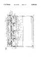
- FIG. 1is a front side elevational view of a buffered stacker constructed in accordance with the invention
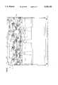
- FIG. 2is a back side elevational view of the buffered stacker of FIG. 1;
- FIG. 3is a diagrammatic view of a control system forming a part of the buffered stacker of FIG. 1.
- a diverting and buffered drop floor stacking system constructed in accordance with the present inventionis indicated generally at 10.
- the system 10may form a portion of a larger high speed system for processing large flat documents, such as envelopes, catalogs and the like. Upstream of the stacking system 10, the documents are typically singulated and a sorting destination is assigned to each document.
- the sorting destinationmay be assigned automatically with an optical code reader or by other methods such as manual key entry or the like.
- the documentsare transported to the stacking system 10 in a horizontal one at a time relationship along a primary conveying path from the upstream stations.
- the illustrated diverter and stacking systemincludes a plurality of sorting stations 11.
- Each of the sorting stations 11includes a diverter assembly, such as indicated at 12, to divert the conveyed document from the primary conveying path to a stacking station 14 also forming a part of the sorting station 11.
- the stacking station 14stacks and aligns the diverted documents.
- the stacked documentsare then dropped into a replaceable receiving bin 16 for subsequent handling.
- the stacking system 10includes an upper endless primary conveying belt, indicated generally at 18, having a lower reach 18a which defines the main conveying path 20.
- the sorting stations 11are disposed serially along the conveying path 20.
- Each of the diverter stations 12includes a diverter arm assembly 24 for selectively diverting documents, being transported down the path 20, into the stacking station 14.
- the diverter arm assembly 24includes a wedged shaped flipper 26 which is attached to the forward end of a generally horizontal shaft 28 disposed generally adjacent the conveying path 20.
- the shaft 28is rotatably journaled in a vertical portion of a support frame 29.
- an actuating lever 30is attached to the rear end of the shaft 28.
- a rod end 31 of a pneumatic actuating cylinder 32is operably attached to the actuating lever 30. Operation of the cylinder 32 pivots the lever 30 to reciprocally rotate the shaft 28.
- the rotation of the shaft 28pivots the flipper 26 between an upwardly angled diverting position 26a, as shown in shadow in FIG. 1, and the horizontal position.
- an upper edge of the flipper 26defines a portion of the horizontal conveying path 20.
- the flipper 26diverts the document being conveyed along the path 20 to the sorting station 11 through a passageway 31 formed between adjacent lower endless belts 34 and into the stacking station 14.
- the longitudinal length of the passageway 31 along the conveying path 20allows the documents to be downwardly tilted by the flipper 26 while minimizing the bending of the document which facilitates the diversion of large or bulky documents.
- the lower endless belt assemblies 34having upper reaches 34a which lie along the conveying path 20 and in juxtaposed contacting relation with the lower reach 18a of the upper belt 18.
- the upper belt 18 and lower belts 34are driven so that the upper reaches 34a of the lower belts and the lower reach 18a of the upper belt travel downstream at the same linear speed along the conveying path 20.
- Adjacent lower belt assemblies 34are separated by one of the diverter assemblies 24.
- the diverter assemblies 24are arranged so that when the flipper 26 is in the horizontal position, an upstream tip 26b of the flipper is downstream and in close proximity to the immediately upstream lower belt 34 to prevent jamming of the document between the flipper and lower belt assembly 34.
- a series of buffer rollers 36may be disposed above and adjacent the lower reach 18a of the upper belt 18 so as to provide a pinch force between the lower reach 18a and the upper reach 34a of lower belt 34.
- the stacking station 14includes a drop floor assembly, indicated generally at 50 to selectively support the diverted documents.
- the drop floor assembly 50includes an upstream planar floor section 52 and downstream planar floor section 54.
- the upstream floor sectionis aligned with the downstream floor section 54 and an inner transverse edge 52a of the upstream floor section 52 is coparallel to and in close proximity to an inner transverse edge 54a of the downstream floor section 54 to form a gap 55 between the edges.
- the inner upstream edge 52a and the inner downstream edge 54amay be directly opposing each other.
- the inner upstream edge 52amay also be slightly higher than the inner downstream edge 54a so that the upstream edge 52a shields the gap 55 to prevent diverted documents from catching on the downstream edge 54a and jamming into the gap 55.
- the upstream floor section 52 and downstream floor section 54define a drop floor 56 which is angled downward in the downstream direction.
- Documents which are diverted into the stacking station 14contact the drop floor 56 and typically slide down the drop floor until a downstream edge of the document strikes an alignment plate 58 which aligns the downstream or leading edge of the documents stacked on the drop floor.
- the alignment plate 58preferably extends upward from a point adjacent the downstream edge 54b of the downstream floor section 54 and in a direction generally normal to the alignment of the drop floor 56 in the document supporting position.
- the floor assembly 50also includes a pivoting mechanism 60 for pivoting the upstream floor section 52 and downstream floor section 54 from the document supporting position to a generally vertical orientation whereby the documents drop into the receiving receptacle 16 located below the drop floor 56.
- the pivoting mechanism 60includes an upstream shaft 64 which is fixedly attached to the upstream edge 52b of the upstream floor section 52, and a downstream shaft 66 which is fixedly attached to the downstream edge 54b of the downstream floor section 54.
- Each of the shafts 64, 66extends through and is rotatably mounted to the vertical support 29.
- the upstream shaft 64is positioned higher than the downstream shaft 66 so that the drop floor 56 is downwardly inclined in the downstream direction.
- a rear end 66a of the downstream shaft 66is attached to a first actuating lever 68.
- the actuating lever 68is operably attached to a rod end 70 of an actuating cylinder 74 which is in turn attached to the vertical support 29. Extension of the rod end 70 pivots the first actuating lever 68 thereby rotating the downstream shaft 66 and pivoting the downstream floor section 54.
- the cylinder 74 and first actuating lever 68are oriented so that the pivoting of the lever causes the downstream floor section 54 to pivot between the document stacking position and the vertical drop position.
- a rear end 64a of the upstream shaft 64is attached to a second actuating lever 76.
- the first actuating lever 68 and second actuating lever 76are interconnected so that pivoting of the first actuating lever causes a similar pivoting of the second actuating lever to operably pivot the upstream floor section 52 between the document stacking position and the vertical drop position.
- the first and second actuating levers 68, 76are preferably interconnected by a rigid rod 78 having ends attached to the first and second actuating levers.
- Other linkages, mechanical, electrical or otherwise,are also contemplated.
- the upstream floor section 52preferably has a longitudinal length which is greater than the longitudinal length of the downstream floor section 54.
- the inner edges 52a and 54a, respectivelyare horizontally aligned.
- the distance between the receiving receptacle 16 and the drop floor 56is sized so that when the upstream and downstream floor sections 52, 54 are pivoted into the vertical orientation, the inner edges 52a and 54a, respectively, extend downward just within the receiving receptacle. Having the edges 52a, 54a just within the receptacle 16 reduces the possibility that the stack of documents previously placed into the receiving receptacle may interfere with the pivoting of the drop floor 56.
- the control device 100includes a controller 101. Providing inputs to the controller 101 are a diverter arm sensor 102 forming a part of each of the diverter stations 12 and a stacking station sensor 104 forming a part of the stacking station 14. Output signals from the controller 101 may be provided to selectively actuate the diverter stations 18 and the pivoting mechanism 60 of the drop floor assemblies 50.
- the diverter sensors 102are operative to sense the leading edge of documents as the documents are conveyed down the conveying path 20.
- each of the diverter stations 12includes a diverter sensor 102 with the diverter sensor located upstream from the corresponding diverter station. The distance upstream should be sufficient so that the control system 100 will have sufficient time to activate the diverter arm assembly 24 when the leading edge of a document to be diverted is sensed.
- Each of the diverter sensors 102includes a light emitting element 102a and a light sensing element 102b disposed on opposite sides of the conveying path 20 although other sensor devices are contemplated.
- Each of the stacking stations 14includes one of the stacking station sensor 104 which determines when the height of the documents stacked upon the drop floor 56 reaches a predetermined height.
- the sensor 104is mounted on the support frame 29 at a distance above the drop floor 56 which corresponds to the desired height of the stack of collected documents before the drop floor assembly 50 is operated.
- the documentsare conveyed horizontally down the primary conveying path 20 and a destination sorting station 11 is assigned to each document.
- the destination sorting station informationis then provided to the controller 102 of the control system 100.
- the documentis then transported to the buffer stacker 10 and fed into the horizontal primary conveying path 20 formed between the upper primary conveying belt 18 and the series of alternating secondary conveying belts 34 and diverter stations 12.
- the control system 100may include a sensor 108 disposed at the beginning of the conveying path 20 to determine when the leading edge of the document passes the sensor to sense when the document enters the sorting system 10. The control system 100 may then monitor the position of the document as the document is conveyed along the path 20 through the sensing of the leading edge of the document by the diverter sensors 102 distributed along the conveying path.
- the controller 102sends an output signal to actuate the actuation cylinder 32 of the diverter arm assembly 24.
- the actuation cylinder 32pivots the flipper 26 into the diverting position.
- the flipper 26diverts the horizontally conveyed document through the passageway 31 between the flipper and the secondary belt 34 of the immediately upstream sorting station 11 and into the stacking station 14.
- the documentthen contacts either the drop floor 56 or documents stacked on the drop floor.
- the generally downstream directional velocity of the document and the downwardly angled inclination of the drop floor 56cause the document to slide along the drop floor or stacked documents until the leading edge strikes the alignment plate 58.
- the alignment plate 58generally aligning the leading edge of the documents stacked on the drop floor.
- the sensorWhen the stack of documents reaches the stacking station sensor 104, the sensor sends an output signal to the controller 101. Once having received a signal from the stacking station sensor 104, the controller 101 determines the appropriate time for activating the drop floor assembly 50 of that stacking station 14. The appropriate time is preferably when no additional documents enter the stacking station 14 during the dropping process to reduce the possibility of documents getting caught in the dropping floor assembly 50 during the dropping process.
- the controller 101preferably activates the drop floor assembly 50 when the output from the reader station indicates that of the documents being transported along the primary conveying path 20, one or more of the documents is not to be diverted into that stacking station 14, thereby creating a gap in the transported documents. Should a predetermined number of additional documents, as counted by the controller 101, be diverted into the stacking station after the stacking station sensor 104 is activated and without a gap occurring, the controller 101 creates a gap by not diverting a document which normally is to be diverted into the stacking station 14.
- the controller 101actuates the pivoting mechanism 60.
- the pivoting mechanism 60pivots the upstream floor 52 and the downstream floor 54 from the document supporting position to the vertical drop position.
- the stacked documentsdrop downward into the receiving receptacle 16, and the upstream floor 52 and the downstream floor 54 are pivoted back into the document supporting position by the pivoting mechanism 60.
- the documentsmaintain their horizontal alignment and their alignment relative to each other by the vacuum effect induced between adjacent documents as the documents drop.
- This vacuum effectis particularly beneficial when the upper documents are flimsy or light.
- the receiving receptacles 16are located directly below the stacking station 14, the width of the footprint of the buffered stacker 10 is reduced. In addition, a full receiving receptacle 16 may be replaced with an empty receptacle without stopping the sorting operation.
Landscapes
- Separation, Sorting, Adjustment, Or Bending Of Sheets To Be Conveyed (AREA)
Abstract
Description
Claims (9)
Priority Applications (1)
| Application Number | Priority Date | Filing Date | Title |
|---|---|---|---|
| US08/326,122US5538140A (en) | 1994-10-19 | 1994-10-19 | Buffered stacker with drop floor assembly |
Applications Claiming Priority (1)
| Application Number | Priority Date | Filing Date | Title |
|---|---|---|---|
| US08/326,122US5538140A (en) | 1994-10-19 | 1994-10-19 | Buffered stacker with drop floor assembly |
Publications (1)
| Publication Number | Publication Date |
|---|---|
| US5538140Atrue US5538140A (en) | 1996-07-23 |
Family
ID=23270906
Family Applications (1)
| Application Number | Title | Priority Date | Filing Date |
|---|---|---|---|
| US08/326,122Expired - LifetimeUS5538140A (en) | 1994-10-19 | 1994-10-19 | Buffered stacker with drop floor assembly |
Country Status (1)
| Country | Link |
|---|---|
| US (1) | US5538140A (en) |
Cited By (14)
| Publication number | Priority date | Publication date | Assignee | Title |
|---|---|---|---|---|
| US5876033A (en)* | 1995-06-26 | 1999-03-02 | Officina Meccanica L.A.R. Di Lonati Lorenzo & C. S.N.C. | Device to stack and collect banknotes with the possibility of returning them |
| US5959868A (en)* | 1995-09-08 | 1999-09-28 | Grapha-Holding Ag | Arrangement for distributing articles for dispatch |
| US6126017A (en)* | 1995-09-08 | 2000-10-03 | Mannesmann Dematic Postal Automation S.A. | Device and method for sorting objects using buffer receptacles at sorting outlets |
| US6316741B1 (en)* | 1999-06-04 | 2001-11-13 | Lockheed Martin Corporation | Object sortation for delivery sequencing |
| US6688083B1 (en)* | 2000-11-17 | 2004-02-10 | Lockheed Martin Corporation | Drop control mechanism for flat articles |
| US20040065596A1 (en)* | 2002-10-08 | 2004-04-08 | Hanson Bruce H. | Method for sequentially ordering objects using a single pass delivery point process |
| US20040069691A1 (en)* | 2002-06-18 | 2004-04-15 | Ed Svyatsky | Progressive modularity assortment system with high and low capacity bins |
| US6749194B2 (en) | 2001-12-05 | 2004-06-15 | Lockheed Martin Corporation | Drop pocket stack height and object count monitoring system and method |
| US20040245157A1 (en)* | 2003-05-09 | 2004-12-09 | Stone Robert L. | Sensors for article sorter |
| EP1315582A4 (en)* | 2000-06-26 | 2007-12-26 | Us Postal Service | METHOD AND SYSTEM FOR PROCESSING LETTERS AND FLAT OBJECTS IN A SINGLE CIRCULATION |
| US7384041B2 (en) | 2004-09-02 | 2008-06-10 | Dst Output | Mailing piece buffer system |
| US7862039B1 (en)* | 2004-04-27 | 2011-01-04 | Pitney Bowes Inc. | Multi-bin printer |
| US10556253B2 (en)* | 2018-04-27 | 2020-02-11 | Amazon Technologies, Inc. | Parcel sorting apparatus with routing manifold and diverter system |
| CN116532393A (en)* | 2023-04-12 | 2023-08-04 | 盐城雄鹰精密机械有限公司 | Solid wood floor grade sorting and stacking production line |
Citations (8)
| Publication number | Priority date | Publication date | Assignee | Title |
|---|---|---|---|---|
| US2765167A (en)* | 1953-05-22 | 1956-10-02 | American Can Co | Blank stacking mechanism with blank intercepting elements |
| US2767534A (en)* | 1951-10-26 | 1956-10-23 | Johnson & Johnson | Art of sheet delivery and stacking |
| US3799540A (en)* | 1971-09-15 | 1974-03-26 | Bucciconi Eng Co | Sheet piler |
| US3901797A (en)* | 1974-06-05 | 1975-08-26 | Pitney Bowes Inc | Automatic continuous mail handling system |
| US4162733A (en)* | 1977-06-21 | 1979-07-31 | Wiseman Raymond L | Article stacking apparatus |
| US4493484A (en)* | 1981-10-09 | 1985-01-15 | Hotchkiss-Brandt-Sogeme-H.B.S. | Device for guiding and receiving letters at the exit of a mail-sorting machine and a machine equipped with said device |
| US4657094A (en)* | 1986-04-07 | 1987-04-14 | Package Machinery Company | Fill height detector in weighing and packaging system |
| US5186336A (en)* | 1991-01-22 | 1993-02-16 | Electrocom Automation L.P. | Product sorting apparatus |
- 1994
- 1994-10-19USUS08/326,122patent/US5538140A/ennot_activeExpired - Lifetime
Patent Citations (8)
| Publication number | Priority date | Publication date | Assignee | Title |
|---|---|---|---|---|
| US2767534A (en)* | 1951-10-26 | 1956-10-23 | Johnson & Johnson | Art of sheet delivery and stacking |
| US2765167A (en)* | 1953-05-22 | 1956-10-02 | American Can Co | Blank stacking mechanism with blank intercepting elements |
| US3799540A (en)* | 1971-09-15 | 1974-03-26 | Bucciconi Eng Co | Sheet piler |
| US3901797A (en)* | 1974-06-05 | 1975-08-26 | Pitney Bowes Inc | Automatic continuous mail handling system |
| US4162733A (en)* | 1977-06-21 | 1979-07-31 | Wiseman Raymond L | Article stacking apparatus |
| US4493484A (en)* | 1981-10-09 | 1985-01-15 | Hotchkiss-Brandt-Sogeme-H.B.S. | Device for guiding and receiving letters at the exit of a mail-sorting machine and a machine equipped with said device |
| US4657094A (en)* | 1986-04-07 | 1987-04-14 | Package Machinery Company | Fill height detector in weighing and packaging system |
| US5186336A (en)* | 1991-01-22 | 1993-02-16 | Electrocom Automation L.P. | Product sorting apparatus |
Cited By (17)
| Publication number | Priority date | Publication date | Assignee | Title |
|---|---|---|---|---|
| US5876033A (en)* | 1995-06-26 | 1999-03-02 | Officina Meccanica L.A.R. Di Lonati Lorenzo & C. S.N.C. | Device to stack and collect banknotes with the possibility of returning them |
| US5959868A (en)* | 1995-09-08 | 1999-09-28 | Grapha-Holding Ag | Arrangement for distributing articles for dispatch |
| US6126017A (en)* | 1995-09-08 | 2000-10-03 | Mannesmann Dematic Postal Automation S.A. | Device and method for sorting objects using buffer receptacles at sorting outlets |
| US6316741B1 (en)* | 1999-06-04 | 2001-11-13 | Lockheed Martin Corporation | Object sortation for delivery sequencing |
| EP1315582A4 (en)* | 2000-06-26 | 2007-12-26 | Us Postal Service | METHOD AND SYSTEM FOR PROCESSING LETTERS AND FLAT OBJECTS IN A SINGLE CIRCULATION |
| US6688083B1 (en)* | 2000-11-17 | 2004-02-10 | Lockheed Martin Corporation | Drop control mechanism for flat articles |
| US6749194B2 (en) | 2001-12-05 | 2004-06-15 | Lockheed Martin Corporation | Drop pocket stack height and object count monitoring system and method |
| US20040069691A1 (en)* | 2002-06-18 | 2004-04-15 | Ed Svyatsky | Progressive modularity assortment system with high and low capacity bins |
| US7498539B2 (en)* | 2002-06-18 | 2009-03-03 | Bowe Bell & Howell Company | Progressive modularity assortment system with high and low capacity bins |
| US20040065596A1 (en)* | 2002-10-08 | 2004-04-08 | Hanson Bruce H. | Method for sequentially ordering objects using a single pass delivery point process |
| US6921875B2 (en)* | 2002-10-08 | 2005-07-26 | Lockheed Martin Corporation | Method for sequentially ordering objects using a single pass delivery point process |
| US20040245157A1 (en)* | 2003-05-09 | 2004-12-09 | Stone Robert L. | Sensors for article sorter |
| US7213698B2 (en) | 2003-05-09 | 2007-05-08 | Siemens Energy & Automation | Sensors for article sorter |
| US7862039B1 (en)* | 2004-04-27 | 2011-01-04 | Pitney Bowes Inc. | Multi-bin printer |
| US7384041B2 (en) | 2004-09-02 | 2008-06-10 | Dst Output | Mailing piece buffer system |
| US10556253B2 (en)* | 2018-04-27 | 2020-02-11 | Amazon Technologies, Inc. | Parcel sorting apparatus with routing manifold and diverter system |
| CN116532393A (en)* | 2023-04-12 | 2023-08-04 | 盐城雄鹰精密机械有限公司 | Solid wood floor grade sorting and stacking production line |
Similar Documents
| Publication | Publication Date | Title |
|---|---|---|
| US10906746B2 (en) | Article typing and sorting system | |
| EP2882650B1 (en) | Parcel handling method | |
| CA1300553C (en) | Apparatus for the automated processing of bulk mail and the like | |
| US5538140A (en) | Buffered stacker with drop floor assembly | |
| US10358298B2 (en) | Slide sorter pop-up diverting conveyor with transfer rate based on article characteristics | |
| US5794790A (en) | Apparatus and method of sorting objects | |
| US4119194A (en) | System and apparatus for the orientation and bidirectional feed of indicia bearing mail | |
| US5695071A (en) | Small flats sorter | |
| US5186336A (en) | Product sorting apparatus | |
| US5226547A (en) | Mail transport assembly for mail sorting system | |
| US5464099A (en) | Method for the automated processing of documents and bulk mail | |
| US5190282A (en) | Multi-pass sorting machine | |
| US5960963A (en) | Sorting device for an inserting system | |
| US5150894A (en) | Diverter mechanism for flat document conveyor system | |
| US5542547A (en) | Document sorting section having a plurality of primary sorting paths | |
| US3235101A (en) | Semi-automatic transferring apparatus | |
| US6398204B1 (en) | On-edge stacking apparatus | |
| US5971161A (en) | Mailpiece sorting device | |
| JP3943174B2 (en) | Discharge hopper that receives upper and lower articles at the same time and method for classifying upper and lower articles | |
| US5503388A (en) | Buffered stacker | |
| US4121403A (en) | Flat mail sorter and loader | |
| US7960668B2 (en) | Method and device for sorting postal items | |
| US6682067B1 (en) | Offset device for an on-edge stacking apparatus | |
| JP2006516471A (en) | Thin stacking compartment for flat mail | |
| EP0876980B1 (en) | Apparatus of feeding and sorting objects |
Legal Events
| Date | Code | Title | Description |
|---|---|---|---|
| AS | Assignment | Owner name:BELL & HOWELL COMPANY, ILLINOIS Free format text:ASSIGNMENT OF ASSIGNORS INTEREST;ASSIGNORS:GUENTHER, KENNETH L.;FABER, THOMAS;KALIKA, JOSEPH;AND OTHERS;REEL/FRAME:007267/0696;SIGNING DATES FROM 19941019 TO 19941020 | |
| STCF | Information on status: patent grant | Free format text:PATENTED CASE | |
| FPAY | Fee payment | Year of fee payment:4 | |
| AS | Assignment | Owner name:HELLER FINANCIAL INC., ILLINOIS Free format text:SECURITY AGREEMENT;ASSIGNOR:BELL & HOWELL MAIL AND MESSAGING TECHNOLOGIES COMPANY;REEL/FRAME:012199/0004 Effective date:20010928 | |
| AS | Assignment | Owner name:BELL & HOWELL COMPANY, ILLINOIS Free format text:CHANGE OF NAME;ASSIGNOR:BELL & HOWELL OPERATING COMPANY;REEL/FRAME:013269/0572 Effective date:20010604 Owner name:BELL & HOWELL OPERATING COMPANY, ILLINOIS Free format text:CHANGE OF NAME;ASSIGNOR:BELL & HOWELL COMPANY;REEL/FRAME:013269/0258 Effective date:19951116 Owner name:PROQUEST COMPANY, MICHIGAN Free format text:MERGER;ASSIGNOR:BELL & HOWELL COMPANY;REEL/FRAME:013288/0849 Effective date:20010604 | |
| AS | Assignment | Owner name:HELLER FINANCIAL, INC., AS AGENT, ILLINOIS Free format text:SECURITY AGREEMENT;ASSIGNOR:BELL & HOWELL COMPANY;REEL/FRAME:013964/0646 Effective date:20030411 | |
| AS | Assignment | Owner name:BBH, INC., ILLINOIS Free format text:ASSIGNMENT OF ASSIGNORS INTEREST;ASSIGNOR:HELLER FINANCIAL, INC., AS AGENT;REEL/FRAME:014580/0954 Effective date:20030929 Owner name:BOWE BELL + HOWELL COMPANY, NORTH CAROLINA Free format text:RELEASE AND REASSIGNMENT;ASSIGNOR:HELLER FINANCIAL, INC., AS AGENT;REEL/FRAME:014560/0414 Effective date:20030929 | |
| FPAY | Fee payment | Year of fee payment:8 | |
| AS | Assignment | Owner name:BBH, INC., ILLINOIS Free format text:CHANGE OF NAME;ASSIGNOR:BELL & HOWELL COMPANY;REEL/FRAME:014953/0695 Effective date:20030922 | |
| AS | Assignment | Owner name:HARRIS TRUST AND SAVINGS BANK, AS AGENT, ILLINOIS Free format text:SECURITY AGREEMENT;ASSIGNOR:BBH, INC.;REEL/FRAME:015027/0561 Effective date:20030925 | |
| FPAY | Fee payment | Year of fee payment:12 | |
| REMI | Maintenance fee reminder mailed | ||
| AS | Assignment | Owner name:HARRIS N.A., AS SECURED PARTY, ILLINOIS Free format text:SECURITY AGREEMENT;ASSIGNOR:BBH, INC.;REEL/FRAME:022694/0247 Effective date:20090513 | |
| AS | Assignment | Owner name:PNC BANK, NATIONAL ASSOCIATION, PENNSYLVANIA Free format text:SECURITY AGREEMENT;ASSIGNORS:BELL AND HOWELL, LLC;BELL AND HOWELL BCC, LLC;REEL/FRAME:026598/0456 Effective date:20110623 | |
| AS | Assignment | Owner name:CONTRADO BBH FUNDING 2, LLC, PENNSYLVANIA Free format text:SECURITY INTEREST (SUBORDINATED LOAN);ASSIGNOR:BELL AND HOWELL, LLC;REEL/FRAME:026722/0845 Effective date:20110623 | |
| AS | Assignment | Owner name:BELL & HOWELL COMPANY, ILLINOIS Free format text:MERGER AND CHANGE OF NAME EFFECTIVE 10/16/2001;ASSIGNORS:BELL & HOWELL COMPANY MERGING INTO;BH ACQUISITION, INC.;REEL/FRAME:026766/0411 Effective date:20011016 | |
| AS | Assignment | Owner name:BELL AND HOWELL, LLC, NORTH CAROLINA Free format text:BANKRUPTCY COURT ORDER RELEASING ALL LIENS;ASSIGNOR:HARRIS N.A. FOR ITSELF AND AS SUCCESSOR BY MERGER TO HARRIS TRUST AND SAVINGS BANK;REEL/FRAME:027139/0160 Effective date:20110602 | |
| AS | Assignment | Owner name:PNC BANK, NATIONAL ASSOCIATION, OHIO Free format text:RELEASE BY SECURED PARTY;ASSIGNORS:BELL AND HOWELL, LLC;BELL AND HOWELL BCC, LLC;REEL/FRAME:036552/0376 Effective date:20150904 | |
| AS | Assignment | Owner name:BELL AND HOWELL, LLC, NORTH CAROLINA Free format text:RELEASE OF INTELLECTUAL PROPERTY SECURITY INTERESTS RECORDED AT R/F 26722/0845;ASSIGNOR:CONTRADO BBH FUNDING 2, LLC, AS SECURED PARTY;REEL/FRAME:048961/0714 Effective date:20181207 |