US5537997A - Sleep apnea treatment apparatus and passive humidifier for use therewith - Google Patents
Sleep apnea treatment apparatus and passive humidifier for use therewithDownload PDFInfo
- Publication number
- US5537997A US5537997AUS08/484,526US48452695AUS5537997AUS 5537997 AUS5537997 AUS 5537997AUS 48452695 AUS48452695 AUS 48452695AUS 5537997 AUS5537997 AUS 5537997A
- Authority
- US
- United States
- Prior art keywords
- patient
- gas flow
- airway
- flow generator
- conduit
- Prior art date
- Legal status (The legal status is an assumption and is not a legal conclusion. Google has not performed a legal analysis and makes no representation as to the accuracy of the status listed.)
- Expired - Lifetime
Links
Images


Classifications
- A—HUMAN NECESSITIES
- A61—MEDICAL OR VETERINARY SCIENCE; HYGIENE
- A61M—DEVICES FOR INTRODUCING MEDIA INTO, OR ONTO, THE BODY; DEVICES FOR TRANSDUCING BODY MEDIA OR FOR TAKING MEDIA FROM THE BODY; DEVICES FOR PRODUCING OR ENDING SLEEP OR STUPOR
- A61M16/00—Devices for influencing the respiratory system of patients by gas treatment, e.g. ventilators; Tracheal tubes
- A61M16/0057—Pumps therefor
- A61M16/0066—Blowers or centrifugal pumps
- A61M16/0069—Blowers or centrifugal pumps the speed thereof being controlled by respiratory parameters, e.g. by inhalation
- A—HUMAN NECESSITIES
- A61—MEDICAL OR VETERINARY SCIENCE; HYGIENE
- A61M—DEVICES FOR INTRODUCING MEDIA INTO, OR ONTO, THE BODY; DEVICES FOR TRANSDUCING BODY MEDIA OR FOR TAKING MEDIA FROM THE BODY; DEVICES FOR PRODUCING OR ENDING SLEEP OR STUPOR
- A61M16/00—Devices for influencing the respiratory system of patients by gas treatment, e.g. ventilators; Tracheal tubes
- A61M16/0051—Devices for influencing the respiratory system of patients by gas treatment, e.g. ventilators; Tracheal tubes with alarm devices
- A—HUMAN NECESSITIES
- A61—MEDICAL OR VETERINARY SCIENCE; HYGIENE
- A61M—DEVICES FOR INTRODUCING MEDIA INTO, OR ONTO, THE BODY; DEVICES FOR TRANSDUCING BODY MEDIA OR FOR TAKING MEDIA FROM THE BODY; DEVICES FOR PRODUCING OR ENDING SLEEP OR STUPOR
- A61M16/00—Devices for influencing the respiratory system of patients by gas treatment, e.g. ventilators; Tracheal tubes
- A61M16/021—Devices for influencing the respiratory system of patients by gas treatment, e.g. ventilators; Tracheal tubes operated by electrical means
- A61M16/022—Control means therefor
- A61M16/024—Control means therefor including calculation means, e.g. using a processor
- A—HUMAN NECESSITIES
- A61—MEDICAL OR VETERINARY SCIENCE; HYGIENE
- A61M—DEVICES FOR INTRODUCING MEDIA INTO, OR ONTO, THE BODY; DEVICES FOR TRANSDUCING BODY MEDIA OR FOR TAKING MEDIA FROM THE BODY; DEVICES FOR PRODUCING OR ENDING SLEEP OR STUPOR
- A61M16/00—Devices for influencing the respiratory system of patients by gas treatment, e.g. ventilators; Tracheal tubes
- A61M16/10—Preparation of respiratory gases or vapours
- A61M16/14—Preparation of respiratory gases or vapours by mixing different fluids, one of them being in a liquid phase
- A61M16/16—Devices to humidify the respiration air
- A—HUMAN NECESSITIES
- A61—MEDICAL OR VETERINARY SCIENCE; HYGIENE
- A61M—DEVICES FOR INTRODUCING MEDIA INTO, OR ONTO, THE BODY; DEVICES FOR TRANSDUCING BODY MEDIA OR FOR TAKING MEDIA FROM THE BODY; DEVICES FOR PRODUCING OR ENDING SLEEP OR STUPOR
- A61M16/00—Devices for influencing the respiratory system of patients by gas treatment, e.g. ventilators; Tracheal tubes
- A61M16/0003—Accessories therefor, e.g. sensors, vibrators, negative pressure
- A61M2016/0015—Accessories therefor, e.g. sensors, vibrators, negative pressure inhalation detectors
- A61M2016/0018—Accessories therefor, e.g. sensors, vibrators, negative pressure inhalation detectors electrical
- A61M2016/0021—Accessories therefor, e.g. sensors, vibrators, negative pressure inhalation detectors electrical with a proportional output signal, e.g. from a thermistor
- A—HUMAN NECESSITIES
- A61—MEDICAL OR VETERINARY SCIENCE; HYGIENE
- A61M—DEVICES FOR INTRODUCING MEDIA INTO, OR ONTO, THE BODY; DEVICES FOR TRANSDUCING BODY MEDIA OR FOR TAKING MEDIA FROM THE BODY; DEVICES FOR PRODUCING OR ENDING SLEEP OR STUPOR
- A61M16/00—Devices for influencing the respiratory system of patients by gas treatment, e.g. ventilators; Tracheal tubes
- A61M16/0003—Accessories therefor, e.g. sensors, vibrators, negative pressure
- A61M2016/0027—Accessories therefor, e.g. sensors, vibrators, negative pressure pressure meter
- A—HUMAN NECESSITIES
- A61—MEDICAL OR VETERINARY SCIENCE; HYGIENE
- A61M—DEVICES FOR INTRODUCING MEDIA INTO, OR ONTO, THE BODY; DEVICES FOR TRANSDUCING BODY MEDIA OR FOR TAKING MEDIA FROM THE BODY; DEVICES FOR PRODUCING OR ENDING SLEEP OR STUPOR
- A61M16/00—Devices for influencing the respiratory system of patients by gas treatment, e.g. ventilators; Tracheal tubes
- A61M16/0003—Accessories therefor, e.g. sensors, vibrators, negative pressure
- A61M2016/003—Accessories therefor, e.g. sensors, vibrators, negative pressure with a flowmeter
- A61M2016/0033—Accessories therefor, e.g. sensors, vibrators, negative pressure with a flowmeter electrical
- A61M2016/0036—Accessories therefor, e.g. sensors, vibrators, negative pressure with a flowmeter electrical in the breathing tube and used in both inspiratory and expiratory phase
Definitions
- the present inventionrelates generally methodology and apparatus for treatment of sleep apnea and, more particularly, to mono-level, bi-level and variable positive airway pressure apparatus.
- the sleep apnea syndromeafflicts an estimated 1% to 5% of the general population and is due to episodic upper airway obstruction during sleep. Those afflicted with sleep apnea experience sleep fragmentation and intermittent, complete or nearly complete cessation of ventilation during sleep with potentially severe degrees of oxyhemoglobin desaturation. These features may be translated clinically into extreme daytime sleepiness, cardiac arrhythmias, pulmonary-artery hypertension, congestlye heart failure and/or cognitive dysfunction. Other sequelae of sleep apnea include right ventricular dysfunction with cor pulmonale, carbon dioxide retention during wakefulness as well as during sleep, and continuous reduced arterial oxygen tension. Hypersomnolent sleep apnea patients may be at risk for excessive mortality from these factors as well as by an elevated risk for accidents while driving and/or operating potentially dangerous equipment.
- the mechanismincludes either anatomic or functional abnormalities of the upper airway which result in increased air flow resistance. Such abnormalities may include narrowing of the upper airway due to suction forces evolved during inspiration, the effect of gravity pulling the tongue back to appose the pharyngeal wall, and/or insufficient muscle tone in the upper airway dilator muscles. It has also been hypothesized that a mechanism responsible for the known association between obesity and sleep apnea is excessive soft tissue in the anterior and lateral neck which applies sufficient pressure on internal structures to narrow the airway.
- the treatment of sleep apneahas included such surgical interventions as uvulopalatopharyngoplasty, gastric surgery for obesity, and maxillo-facial reconstruction.
- Another mode of surgical intervention used in the treatment of sleep apneais tracheostomy.
- Pharmacologic therapyhas in general been disappointing, especially in patients with more than mild sleep apnea.
- side effects from the pharmacologic agents that have been usedare frequent.
- medical practitionerscontinue to seek non-invasive modes of treatment for sleep apnea with high success rates and high patient compliance including, for example in cases relating to obesity, weight loss through a regimen of exercise and regulated diet.
- CPAPcontinuous positive airway pressure
- U.S. Pat. No. 4,655,213discloses sleep apnea treatments based on continuous positive airway pressure applied within the airway of the patient.
- U.S. Pat. Nos. 5,245,995 5,199,424, and 5,335,654, and published PCT Application No. WO 88/10108describes a CPAP apparatus which includes a feedback/diagnostic system for controlling the output pressure of a variable pressure air source whereby output pressure from the air source is increased in response to detection of sound indicative of snoring.
- the apparatus disclosed in these documentsfurther include means for reducing the CPAP level to a minimum level to maintain unobstructed breathing in the absence of breathing patterns indicative of obstructed breathing, e.g., snoring.
- bi-level positive airway therapyfor treatment of sleep apnea and related disorders is taught in U.S. Pat. No. 5,148,802.
- pressureis applied alternately at relatively higher and lower prescription pressure levels within the airway of the patient so that the pressure-induced patent force applied to the patients airway is alternately a larger and a smaller magnitude force.
- IPAPinspiratory positive airway pressure
- EPAPexpiratory positive airway pressure
- bi-level therapyThis method of treatment may descriptively be referred to as bi-level therapy.
- EPAPwhich has the greater impact upon patient comfort.
- the treating physicianmust be cognizant of maintaining EPAP as low as is reasonably possible to maintain sufficient pharyngeal patency during expiration, while optimizing user tolerance and efficiency of the therapy.
- Both inspiratory and expiratory air flow resistances in the airwayare elevated during sleep preceding the onset of apnea, although the airway flow resistance may be less during expiration than during inspiration.
- the bi-level therapy as characterized aboveshould be sufficient to maintain pharyngeal patency during expiration even though the pressure applied during expiration is generally not as high as that needed to maintain pharyngeal patency during inspiration.
- some patientsmay have increased upper airway resistance primarily during inspiration with resulting adverse physiologic consequences.
- elevated pressuremay be applied only during inhalation thus eliminating the need for global (inhalation and exhalation) increases in airway pressure.
- the relatively lower pressure applied during expirationmay in some cases approach or equal ambient pressure.
- the lower pressure applied in the airway during expirationenhances patient tolerance by alleviating some of the uncomfortable sensations normally associated with mono-level CPAP.
- the CPAP apparatus disclosed in U.S. Pat. Nos. 5,245,995 5,199,424, and 5,335,654, and published PCT Application No. WO 88/10108provide feedback/diagnostic systems including at least one sensor (typically an audio transducer such as a microphone) in communication with the patient's respiratory system.
- This sensoris located on or is connected to means (such as a breathing mask or nasal prongs) in sealed air communication with a patient's respiratory system.
- the sensorcontinuously senses the patient's breathing patterns and transmits signals indicative of those patterns to information processing means which control the motor speed of a blower.
- the breathing pattern signalscan also be continuously monitored and/or recorded, thereby imparting to the apparatus a diagnostic as well as therapeutic capability.
- the blowerdelivers pressurized air to the patient through a length of conduit and the breathing mask or nasal prongs.
- the sensordetects breathing patterns indicative of obstructed breathing, e.g., snoring, it transmit signals corresponding to this condition to the information processing means which causes an increase in blower motor speed and, therefore, blower pressure output, until unobstructed breathing is eliminated.
- the systemalso includes logic whereby blower motor speed (and blower pressure output) is gradually decreased if unobstructed breathing patterns are detected over a preselected period of time. The purpose of this feature is to provide the patient with a pressure minimally sufficient to maintain airway patency during unobstructed breathing, thereby enhancing patient comfort and therapy compliance.
- certain feedback/diagnostic systemsutilize a breathing pattern sensor mounted on or connected to the breathing mask or nasal prongs. Such an arrangement requires a length of feedback conduit to be added to the patient's breathing circuit.
- the feedback conduitextends from the breathing patterns sensor at the mask to the blower.
- Such an added feedback conduitrenders the patient's breathing circuit cumbersome and increases the risk of entanglement of the feedback circuit.
- the arrangementalso increases the risk of the feedback conduit becoming kinked or having the conduit accidently disconnected from the breathing mask, either of which render the device inoperable.
- Such a feedback conduitalso requires frequent cleaning because it is in contact with the patient's expired air.
- a problem associated with positive airway pressure devicesis a lack of moisture in the air delivered by these devices has a drying effect on patient airways which causes the patient to have considerable discomfort and difficulty sleeping.
- Humidifiershave been developed for use with CPAP devices to humidify the air supplied to the patient.
- any type of accessorysuch as a humidifier may attenuate or absorb snore sound.
- Humidifiers for use with CPAP apparatusare taught in U.S. Pat. Nos. 4,807,616 and 5,231,979.
- Other humidifiers of interestare manufactured by Respironics, Inc. of Murrysville, Pa. and Healthdyne Technologies.
- Respironics, Inc.of Murrysville, Pa.
- Healthdyne Technologiesare for use with conventional CPAP apparatus and therefore are not configured to acoustically tune snoring sound as required for use with the unique sleep apnea treatment apparatus of the present invention.
- the present inventioncontemplates a novel and improved method for treatment of sleep apnea as well as novel methodology and apparatus for carrying out such improved treatment method.
- the inventioncontemplates the treatment of sleep apnea through application of pressure at variance with ambient atmospheric pressure within the upper airway of the patient in a manner to promote patency of the airway to thereby relieve upper airway occlusion during sleep.
- positive pressuremay be applied at a substantially constant, "mono-level,” patient-specific prescription pressure, at alternatively higher (IPAP) and lower (EPAP) "bi-level” pressures, or at variable pressures within the airway of the patient to maintain the requisite patent or "splint" force to sustain respiration during sleep periods.
- the apparatus for delivering pressurized breathing gas to the airway of a patientcomprises a breathing gas flow generator, information processing means for controlling the output of the gas flow generator, and a length of flexible conduit connected at one end to the gas flow generator and at an opposite end to a patient interface means such as a breathing mask or nasal prongs.
- the information processing meansBy controlling the output of the gas flow generator, the information processing means likewise controls the pressure of the breathing gas delivered to the patient through the flexible conduit and the patient interface means.
- the apparatusfurther includes a novel feedback system which may impart both therapeutic as well as diagnostic capability to the apparatus.
- the feedback systemincludes at least one sensor means, such as a pressure or flow responsive transducer, located on, within or closely adjacent to the gas flow generator.
- the sensor meanscontinuously senses the patient's breathing patterns and transmits signals indicative of those patterns to the information processing means.
- the apparatusmay also include means whereby these signals can also be continuously monitored and/or recorded whereby the patient's specific breathing disorder may be diagnosed as well as treated by the apparatus.
- the sensorwhen it detects breathing patterns indicative of obstructed breathing, it transmits signals corresponding to this condition to the information processing means.
- This meanswhich may be any suitable microprocessor or central processing unit (CPU), then causes the flow generator to increase its output which increases the air pressure delivered to the patient until obstructed breathing is no longer detected.
- the systemalso includes logic whereby the flow generator output is gradually decreased if unobstructed breathing patterns are detected over a preselected period of time. This feature serves to provide the patient with a pressure minimally sufficient to maintain airway patency during unobstructed breathing, thus enhancing patient comfort and therapy compliance.
- the apparatusfinds its breathing patterns sensor situated generally at the end of the breathing circuit remote from the patient. That is, the sensor is preferably located within, on or is connected closely adjacent to the outlet of the gas flow generator controller. Situating the breathing patterns sensor at this region of the breathing circuit realizes considerable improvements in apparatus performance characteristics and in particular sensor reliability and ease of use.
- the breathing patterns sensorfrom the patient interface (i.e., the breathing mask or nasal prongs)
- that portion of the along the patient's breathing circuitis eliminated, and only a relatively shorter feedback conduit is required and is provided. Consequently, the patient's breathing circuit is rendered considerably less cumbersome, the risk of entanglement is negatived, and any annoyance of the patient is minimized.
- the length of the shorter feedback conduitreduces, if not totally eliminates, the risk of being kinked or accidently disconnected from the patient's breathing circuit. Additionally, frequent cleaning of the shorter feedback conduit is not required because it is not in direct contact with the patient's expired air.
- the shorter feedback conduitalso reduces the materials cost for the system.
- the breathing patterns sensorsubstantially at or near the gas flow generator reduces the responsiveness of the apparatus to the patient's continually changing respiratory needs.
- the reduction in responsiveness of the breathing patterns sensoris compensated for by resonant tuning of the system. That is, the frequency response of the patient's breathing circuit and internal tubing of the present system is acoustically tuned to optimally transmit sounds with frequency content which is known to be indicative of upper airway obstructions.
- the tuned resonanceis such that sounds (snores) with frequencies near the resonant frequency are amplified, thus boosting the signal-to-noise ratio (more accurately the ratio of snore noise to gas flow generator noise) back to the level which is comparable to that which has been obtained by sensing at the patient interface.
- a patient's lack of demand or a reduced demand for inspiratory airoften precedes, frequently by several seconds, by the onset of an audible snore or other pronounced physical manifestation indicative of obstructed breathing.
- the breathing pattern sensorstypically must detect such salient occurrences before they register an obstructed breathing event. In such case, the sensor would transmit data to the CPU such that the CPU could step up the output of the flow generator well in advance of not only an apneic event but also prior-to the characteristic audible snore patterns which normally precede such an event.
- Known breathing pattern sensorstypically accomplish this while being located on or connected to the patient interface.
- the sensor of the present inventionmay be an equally responsive pressure or flow transducer sensitive to pressure or flow variations of any selected magnitude and/or frequency, but located within, on or connected closely adjacent to the outlet of the gas flow generator.
- the humidifiermay attenuate or absorb snore sound.
- the humidifier in the present inventionwhich includes a U-shaped accumulation chamber which is configured to acoustically tune the snoring sound received from a patient.
- the humidifier of the present inventionis disclosed in more detail in U.S. patent application Ser. No. 08/467,017, entitled “Passive Humidifier for Positive Airway Pressure Devices", the disclosure of which is hereby incorporated by reference.
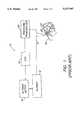
- FIG. 1is a functional block diagram of a prior art CPAP apparatus including a patient feedback/diagnostic system
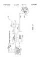
- FIG. 2is a functional block diagram showing a preferred embodiment of the present invention
- FIG. 3is a functional block diagram of a further preferred embodiment of the present invention.
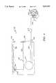
- FIG. 4is a view schematically illustrating a preferred embodiment of the present invention.
- FIG. 5is a view schematically illustrating the sleep apnea treatment apparatus of the present invention in use with a humidifier of the present invention
- FIG. 6is a perspective view of a humidifier of a first embodiment of the present invention showing a humidifier top and a humidifier base in assembled condition;
- FIG. 7is a plan view of a humidifier top of a presently preferred second embodiment viewed from the bottom.
- FIG. 1there is generally indicated at 10 in FIG. 1, in the form of a functional block diagram, a mono-level CPAP apparatus including a patient feedback/diagnostic system generally and schematically representative of the apparatus disclosed in U.S. Pat. Nos. 5,245,995 5,199,424, and 5,335,654, and published PCT Application No. WO 88/10108.
- Apparatus 10includes a blower 12 driven by an electric blower motor 14.
- the speed of motor 14 and thus the output of the blower 12is controlled by an information processing means or central processing unit (CPU) 16.
- CPUcentral processing unit
- the output of the bloweris connected by a suitable length of flexible gas delivery conduit means 18 to a patient interface means 20 such as, for example, nasal prongs or, as illustrated, a breathing mask which is in sealed air communication with the airway of a patient 22.
- the patient interface means 20may include suitable exhaust port means, schematically indicated at 24, for exhaust of breathing gas during expiration.
- Exhaust port means 24may be a conventional non-rebreathing valve or one or more continuously open ports which impose a predetermined flow resistance against exhaust gas flow.
- Apparatus 10also includes a suitable pressure transducer 26 located on or connected to the patient interface means 20.
- the pressure transducer 26is an audio transducer or microphone.
- the pressure transducerdetects the sounds and feeds corresponding electrical signals to the CPU 16 which, in turn, generates a flow generator motor control signal.
- Such signalincreases the speed of the flow generator motor, thereby increasing output pressure supplied to the patient by the blower 12 through conduit means 18 and the patient interface means 20.
- the systemmay include suitable data storage and retrieval .means (not illustrated) which may be connected to CPU 16 to enable medical personnel to monitor and/or record the patient's breathing patterns and thereby diagnose the patient's particular respiratory disorder and breathing requirements.
- Snoringis itself undesirable not only as it is a disturbance to others but it is strongly believed to be connected with hypertension. If the resultant increase in system output pressure is sufficient to completely stabilize the airway, snoring will cease. If a further snoring sound is detected, the pressure is again incrementally increased. This process is repeated until the upper airway is stabilized and snoring ceases. Hence, the occurrence of obstructive apnea can be eliminated by application of minimum appropriate pressure at the time of use.
- the feedback circuitalso includes means gradually decrease the output pressure if an extended period of snore-free breathing occurs in order to ensure that the pressure is maintained at a level as low as practicable to prevent the onset of apnea.
- This effectcan be achieved, for example, by the CPU 16 which, in the absence of an electronic signal from the pressure transducer 26 indicative of snoring, continuously and gradually reduces the flow generator speed and output pressure over a period of time. If, however, a snore is detected by the first pressure transducer, the CPU will again act to incrementally increase the output of the flow generator.
- the feedback circuit of the present inventionas will be discussed hereinafter in connection with FIG. 2 preferably includes similar means.
- a patient using apparatus 10may connect himself to the apparatus and go to sleep.
- the output pressureis initially at a minimum operating value of, for example, approximately 3 cm H 2 O gauge pressure so as not to cause the previously mentioned operational problems of higher initial pressures.
- the pressure transducer 26will then respond to a snore, or snore pattern, and via the CPU 16 increase the blower motor speed such that output pressure increases, for instance, by 1 cm H 2 O for each snore detected.
- the pressurecan be increased relatively rapidly, if the patient's condition so requires, to a working pressure of the order of 8-20 cm, which is a typical requirement. Additionally, for ease of monitoring the variation over time a parameter such as pressure output can be recorded in some convenient retrievable form and medium (such as the aforesaid data storage and retrieval means) for periodic study by medical personnel.
- apparatus 10will not increase the pressure until needed, that is, unless the airway becomes unstable and snoring commences, no increase in airway pressure is made.
- the pressureis never substantially greater than that required to prevent apnea.
- the feedback circuit of FIG. 1provides a system which adjusts apparatus output pressure according to variations in a patient's breathing requirements throughout an entire sleep period. Further, apparatus 10 will likewise accommodate variable output pressure requirements owing to general improvements or deteriorations in a patient's general physical condition as may occur over an extended period of time.
- the present inventionovercomes deficiencies of currently available positive airway pressure apparatus such as apparatus 10 by proposing a novel feedback/diagnostic system which is adapted for use in mono-level, bi-level and variable output positive airway pressure apparatus.
- a novel feedback/diagnostic systemwhich is adapted for use in mono-level, bi-level and variable output positive airway pressure apparatus.
- the inventionwill be described in detail as it may be adapted to mono-level positive airway pressure apparatus, it is further contemplated that the particulars of the present invention may also be gainfully adapted to equally preferred embodiments including bi-level and variable positive airway pressure apparatus, the general characteristics and functions of which are well known in the art.
- the particulars of the "bi-level" and “variable" positive airway pressure apparatus embodiments of the present inventionwill not be described at length.
- Apparatus 110includes a gas flow generator 114 (e.g., a blower) which receives breathing gas from any suitable source such as a pressurized bottle or the ambient atmosphere.
- a gas flow generator 114e.g., a blower
- a sensor means 126Located substantially at, i.e., within, on or connected closely adjacent to, the outlet of the gas flow generator 114 is a sensor means 126 in fluid communication with a flexible gas delivery conduit means 118.
- One end of conduit 118is connected to the outlet of the gas flow generator 114.
- the conduit 118communicates the output of the gas flow generator 114 to a patient interface means or breathing appliance 120 that is connected to the opposite end of the conduit 118.
- the patient interface means 120may be a mask of any suitable known construction which is worn by patient 122 and is in sealed communication with the patient's airway.
- the patient interface means 120may preferably be a nasal mask or a full face mask as illustrated and hereinafter referred.
- Other breathing applianceswhich may be used in lieu of a mask may include nasal cannulae, an endotracheal tube, or any other suitable appliance for interfacing between a source of breathing gas and a patient.
- the mask 120includes suitable exhaust port means, schematically indicated at 124, for exhaust of breathing gases during expiration.
- Exhaust port means 124preferably is a continuously open port provided in the mask 120 or a non-rebreathing valve (NRV) situated closely adjacent the mask in conduit 118.
- the exhaust port meansimposes a suitable flow resistance upon exhaust gas flow to permit an information processing means or central processing unit (CPU) 130, which receives signals generated by sensor means 126 as indicated at 128, to control the output of the gas flow generator in a manner to be described at greater length hereinafter.
- CPUcentral processing unit
- the exhaust port means 124may be of sufficient cross-sectional flow area to sustain a continuous exhaust flow of approximately 15 liters per minute.
- the flow via exhaust port means 124is one component, and typically the major component of the overall system leakage, which is an important parameter of system operation.
- Sensor means 126preferably comprises at least one suitable pressure or flow transducer which continuously detects pressure or flow discharge substantially at the outlet of the gas flow generator, which pressure or flow reflects the patient's breathing patterns. Concurrently, the sensor means 126 generates output signals 128 corresponding to the continuously detected gas pressure or flow from the gas flow generator 114 and transmits these signals to a pressure or flow signal conditioning circuit of the CPU 130 for derivation of a signal proportional to the instantaneous pressure or flow rate of breathing gas within conduit 118.
- Such flow or pressure signal conditioning circuitmay for example be of the type described in U.S. Patent No. 5,148,802, the disclosure of which is incorporated herein by reference.
- the CPUmay generate a command signal 132 to either increase or decrease the output of the gas flow generator 114, e.g., to increase or decrease the speed of an electric motor (not illustrated) thereof.
- the gas flow generator 114, sensor means 126 and CPU 130thus comprise a feedback circuit or system capable of continuously and automatically controlling the breathing pressure supplied to the patient's airway responsive to the patient's respiratory requirements as dictated by the patient's breathing patterns.
- the sensor means 126detects breathing patterns indicative of obstructed breathing, it transmits signals corresponding to this condition to the CPU 130.
- the CPUthen causes the gas flow generator 114 to increase its output which increases the air pressure delivered to the patient until obstructed breathing is no longer detected.
- the systemalso includes means such as appropriate logic programmed into the CPU whereby the gas flow generator output is gradually decreased if unobstructed breathing patterns are detected over a preselected period of time. This feature serves to provide the patient with a pressure minimally sufficient to maintain airway patency during unobstructed breathing, thus enhancing patient comfort and therapy compliance.
- the feedback circuit of the present inventionperforms similarly to the feedback circuits disclosed in previously discussed U.S. Pat. Nos. 5,245,995 and 5,199,424 and published PCT Application No. WO 88/10108.
- the sensor means 126proximate the outlet of the gas flow generator rather than proximate the patient interface means 120 many significant benefits in apparatus performance are realized, which translate into increased patient comfort and therapy compliance.
- the breathing patterns sensorsubstantially at or near the gas flow generator reduces the responsiveness of the apparatus to the patient's continually changing respiratory needs.
- the reduction in responsiveness of the breathing patterns sensoris compensated for by resonant tuning of the system. That is, the frequency response of the patient's breathing circuit and internal tubing of the present system is acoustically tuned to optimally transmit sounds with frequency content which is known to be indicative or upper airway obstructions.
- the tuned resonanceis such that sounds with frequencies near the resonant frequency (snores) are amplified, thus boosting the signal-to-noise ratio (more accurately the ratio of snore noise to gas flow generator noise) back to the level which is comparable to that which has been obtained by sensing at the patient interface.
- the sensor meanswould transmit data to the CPU 130 such that the CPU may step up the output of the gas flow generator 114 well in advance of not only an apneic event but also prior to the characteristic audible snore patterns which normally precede such an event.
- Known breathing pattern sensorstypically accomplish this while being located on or connected to the patient interface.
- the sensor of the present inventionmay be an equally responsive pressure or flow transducer sensitive to pressure or flow variations of any selected magnitude and/or frequency, but located within, on or connected closely adjacent to the outlet of the gas flow generator.
- the feedback circuit of apparatus 110by virtue of the strategic placement of sensor means 126, also affords medical personnel the opportunity to monitor and/or record the patient's breathing activity with high precision. With this capability, the medical personnel may confidently diagnose the patient's particular breathing disorder, prescribe the appropriate therapy, and monitor the patient's progress while undergoing treatment using apparatus 110. In this regard, such monitoring and/or recording may be achieved by system data storage and retrieval means 140.
- System data storage and retrieval means 140may within the scope of the present invention comprise any suitable computer memory into which information can be written and from which information can be read.
- Representative, although not limitative, embodiments of the system data storage and retrieval meansmay therefore include a random access memory (RAM), magnetic tapes or magnetic disks which may be incorporated into a stand-alone personal computer, mainframe computer, or the like (not illustrated).
- RAMrandom access memory
- magnetic tapes or magnetic diskswhich may be incorporated into a stand-alone personal computer, mainframe computer, or the like (not illustrated).
- System data storage and retrieval means 140may be configured to record output data from gas flow generator 114 and/or, as indicated, it may compile data from one or more data input lines 142 which communicate data transmitted by other sensors or monitors (not shown) which are operatively connected to other patients in a manner known to those skilled in the art.
- FIG. 3reveals, in the form of a functional block diagram, an apparatus 210 for use in treatment of sleep apnea and related disorders that is constructed in accordance with a further preferred embodiment of the present invention.
- gas flow generator 214, conduit means 218, patient interface means 220, exhaust port means 224, sensor means 226, CPU 230 and system data storage and retrieval means 240 of FIG. 3desirably are constructed as and function substantially identically to gas flow generator 114, conduit 118, patient interface means 120, exhaust port means 124, sensor means 126, CPU 130 and system data storage and retrieval means 140 discussed hereinabove in connection with FIG. 2.
- apparatus 210The primary distinction between apparatus 210 and apparatus 110 is the presence of a pressure controller 216 which may be controlled separately from and in addition to the gas flow generator 214 by CPU 230.
- the pressure controller 26is thus operative to regulate, at least in part, the pressure of breathing gas within the conduit means 218 and thus within the airway of the patient 222.
- Pressure controller 216is located preferably, although not necessarily, within or closely downstream of flow generator 214 and may take the form of an adjustable valve, the valve being adjustable to provide a constant or variable pressure drop across the valve for all flow rates and thus any desired pressure within conduit means 218.
- a suitable sensor means 226such as a pressure or flow transducer which generates an output signal that is fed as indicated at 228 to a pressure or flow signal conditioning circuit of CPU 230 for derivation of a signal proportional to the instantaneous pressure or flow rate of breathing gas within conduit means 218 to the patient.
- the CPUmay generate and transmit a command signal 232 to increase or decrease the output of the gas flow generator 214 in the manner discussed above in connection with the description of FIG. 2.
- the CPUmay generate and transmit command signal 234 (shown in dashed line) to the pressure controller 216 to adjust the pressure drop produced thereby.
- command signal 234shown in dashed line
- data storage and retrieval means 240may be configured to compile input not only from the gas flow generator 214 and from the patient 222 via input lines 242, but also from the pressure controller 216 to provide the overseeing medical personnel an even more complete representation of the patient's respiratory activity.
- FIG. 4schematically illustrates an arrangement wherein apparatus 310 includes a device 312 incorporating the flow generator 314, breathing patterns sensor means 326, a CPU or central processing unit 330 which includes a pressure controller (not illustrated).
- the flow generator 314presents a bellows 338 terminating in a circuit coupler 344 presented externally of the device 312.
- a patient or first conduit means 318has one end connected to the circuit coupler 344 and an opposite end connected to the patient interface means 320 which includes exhaust port means 324.
- the apparatus 310finds its breathing patterns sensor means 326 situated generally at the end of the breathing circuit remote from the patient 322. That is, the sensor 326 is preferably located within, on or is connected closely adjacent to the outlet of the gas flow generator 314. More specifically, the sensor means 326 comprises a pressure transducer 346 operably connected to the CPU 330. The sensor means 326 is in fluid communication with the patient or first conduit means 318 by means of sensor or second conduit 347.
- the sensor or second conduit means 347comprises a internal conduit portion 348 disposed entirely within the device 312, and an external conduit portion 350 disposed exteriorly of the device 312.
- the sensor or second conduit means 347has one end connected to the pressure transducer 346 and an opposite end connected to the patient or first conduit means 318 through the circuit coupler 344 and thus provide sound pressure communication between the pressure transducer 346 and the patient or first conduit means 318 through the circuit coupler 344.
- the arrangementis such that when the transmitted sound wave is close to the resonant frequency of the system, greatly amplified sound pressure will be transmitted from the mask 320 through the patient or first conduit means 318, the circuit coupler 344, and the sensor or second conduit means 347 to the pressure transducer 346. That is, the system responds like a harmonic oscillator with one degree of freedom.
- the present inventionprovides system that is acoustically tuned to optimally transmit sounds in the frequency range of 20 to 120 Hz (the same range of sounds that are indicative of upper airway obstructions).
- the volume and entrance characteristics of the bellows 338, the blower 314, and the patient circuit 318also affect the resonance properties in a complex manner. Therefore the optimum lengths of the internal and external conduit portions 348, 350 are best verified empirically. This is achieved by placing a sound source at the patient mask 320, sweeping through the range of frequencies of interest, and measuring the output response of the pressure transducer 346. The lengths of the internal and external conduit portions 348, 350 are varied until the desired frequency response is achieved.
- one-eighth inch inner diameter tubingis used as the internal and external conduit portions 348, 350.
- a length L of 40 inches of the internal and external conduit portions 348, 350was found to provide the desired resonant frequency, w of 70 cycles per second.
- the apparatus 310is acoustically tuned to optimally transmit sounds in the target frequency range of 20 to 120 Hz--the primary frequency range of sounds that are indicative of upper airway obstruction. It should be understood, however, that the length L of the internal and external conduits 348, 350 will change with changes in the system elements.
- the particular type of patient circuit 318, blower 314, bellows 338, circuit coupler 344, and pressure transducer 346 used in the systemdo determine the length L of the internal and external conduits 348, 350 that is required to produce the desired resonant frequency of 70 cycles per second.
- the frequencies of sounds associated with upper airway obstructionsare known to fall within a range of about 20 to 2,000 Hz. Therefore, other operative embodiments of the apparatus may be tuned by similar methods to resonant frequencies other than 70 Hz.
- the patient conduit means 318is rendered considerably less cumbersome, the risk of entanglement is negatived, and the annoyance of the patient is minimized.
- the length of the shorter feedback conduitreduces, if not totally eliminates, the risk of being kinked or accidently disconnected from the patient's breathing circuit. Additionally, frequent cleaning of the shorter feedback conduit is not required because it is not in direct contact with the patient's expired air. The shorter feedback conduit also reduces the materials cost for the system.
- FIGS. 5-7a sleep apnea treatment apparatus according to the present invention is illustrated in combination with a humidifier of the present invention.
- the apparatus 310 according to the present inventionincludes a humidifier 400 or 500
- the circuit coupler 344detaches from the gas flow generator device 312 and to an outlet 416 of the humidifier 400 or 500.
- An inlet 415is then connected to the outlet of the gas flow generator device 312.
- humidifier 400has a U-shaped chamber 427 having a first leg 428 which directs air from the body of the humidifier and a second leg 429 which directs air towards the outlet 416.
- the U-shaped chamber 427acoustically tunes the snoring sound received from a patient.
- humidifier 500includes an inlet 516 and a U-shaped chamber 527 having a chamber inlet 543, a diameter transition portion 544 and a laterally extending outlet 515.
- the configuration of the U-shaped chamber 527optimally transmits sound frequencies falling within a frequency range which is known to be associated with upper airway obstructions by setting the resonant frequency of the snore sound.
- the position of the diameter transition portion 544controls the resonant frequency such that the resonant frequency of interest may be selected.
- a dissipation hole 545 between chamber inlet 543 and the outlet portion 516 of U-shaped chamber 427is approximately 0.098 inches in diameter.
- Dissipation hole 545helps dissipate some of that energy to adjust the Q or quality factor (a measure of resonance) of the circuit. Thus, dissipation hole 545 dissipates the energy stored in each oscillation cycle of snore sound to make the Q of the U-shaped chamber 427 comparable to that of the CPAP device.
Landscapes
- Health & Medical Sciences (AREA)
- Life Sciences & Earth Sciences (AREA)
- General Health & Medical Sciences (AREA)
- Engineering & Computer Science (AREA)
- Anesthesiology (AREA)
- Biomedical Technology (AREA)
- Heart & Thoracic Surgery (AREA)
- Hematology (AREA)
- Emergency Medicine (AREA)
- Pulmonology (AREA)
- Public Health (AREA)
- Animal Behavior & Ethology (AREA)
- Veterinary Medicine (AREA)
- Measurement Of The Respiration, Hearing Ability, Form, And Blood Characteristics Of Living Organisms (AREA)
- Orthopedics, Nursing, And Contraception (AREA)
- Percussion Or Vibration Massage (AREA)
- Processing Of Meat And Fish (AREA)
- Air Humidification (AREA)
Abstract
Description
Claims (8)
Priority Applications (12)
| Application Number | Priority Date | Filing Date | Title |
|---|---|---|---|
| US08/484,526US5537997A (en) | 1995-01-26 | 1995-06-07 | Sleep apnea treatment apparatus and passive humidifier for use therewith |
| US08/655,403US5655522A (en) | 1995-01-26 | 1996-05-30 | Sleep apnea treatment apparatus and passive humidifier for use therewith |
| CA002357148ACA2357148C (en) | 1995-06-07 | 1996-06-06 | Sleep apnea treatment apparatus and humidifier |
| DE69632015TDE69632015T2 (en) | 1995-06-07 | 1996-06-06 | SLEEP APNEA TREATMENT DEVICE |
| PCT/US1996/009017WO1996040335A1 (en) | 1995-06-07 | 1996-06-06 | Sleep apnea treatment apparatus and humidifier |
| JP50143697AJP3615224B2 (en) | 1995-06-07 | 1996-06-06 | Device for delivering a flow of respiratory gas to a patient's airway |
| CA002196918ACA2196918C (en) | 1995-06-07 | 1996-06-06 | Sleep apnea treatment apparatus and humidifier |
| EP96918141AEP0777507B1 (en) | 1995-06-07 | 1996-06-06 | Sleep apnea treatment apparatus |
| AU60474/96AAU711721B2 (en) | 1995-06-07 | 1996-06-06 | Sleep apnea treatment apparatus and humidifier |
| AT96918141TATE262939T1 (en) | 1995-06-07 | 1996-06-06 | SLEEP APNEA TREATMENT DEVICE |
| ES96918141TES2218590T3 (en) | 1995-06-07 | 1996-06-06 | APPARATUS FOR THE TREATMENT OF THE SLEEP APNEA. |
| US08/909,118US5947115A (en) | 1995-01-26 | 1997-08-11 | Gas flow pressure filter |
Applications Claiming Priority (2)
| Application Number | Priority Date | Filing Date | Title |
|---|---|---|---|
| US08/378,467US5540219A (en) | 1995-01-26 | 1995-01-26 | Sleep apnea treatment apparatus |
| US08/484,526US5537997A (en) | 1995-01-26 | 1995-06-07 | Sleep apnea treatment apparatus and passive humidifier for use therewith |
Related Parent Applications (1)
| Application Number | Title | Priority Date | Filing Date |
|---|---|---|---|
| US08/378,467Continuation-In-PartUS5540219A (en) | 1995-01-26 | 1995-01-26 | Sleep apnea treatment apparatus |
Related Child Applications (1)
| Application Number | Title | Priority Date | Filing Date |
|---|---|---|---|
| US08/655,403ContinuationUS5655522A (en) | 1995-01-26 | 1996-05-30 | Sleep apnea treatment apparatus and passive humidifier for use therewith |
Publications (1)
| Publication Number | Publication Date |
|---|---|
| US5537997Atrue US5537997A (en) | 1996-07-23 |
Family
ID=23924518
Family Applications (2)
| Application Number | Title | Priority Date | Filing Date |
|---|---|---|---|
| US08/484,526Expired - LifetimeUS5537997A (en) | 1995-01-26 | 1995-06-07 | Sleep apnea treatment apparatus and passive humidifier for use therewith |
| US08/655,403Expired - LifetimeUS5655522A (en) | 1995-01-26 | 1996-05-30 | Sleep apnea treatment apparatus and passive humidifier for use therewith |
Family Applications After (1)
| Application Number | Title | Priority Date | Filing Date |
|---|---|---|---|
| US08/655,403Expired - LifetimeUS5655522A (en) | 1995-01-26 | 1996-05-30 | Sleep apnea treatment apparatus and passive humidifier for use therewith |
Country Status (9)
| Country | Link |
|---|---|
| US (2) | US5537997A (en) |
| EP (1) | EP0777507B1 (en) |
| JP (1) | JP3615224B2 (en) |
| AT (1) | ATE262939T1 (en) |
| AU (1) | AU711721B2 (en) |
| CA (1) | CA2196918C (en) |
| DE (1) | DE69632015T2 (en) |
| ES (1) | ES2218590T3 (en) |
| WO (1) | WO1996040335A1 (en) |
Cited By (122)
| Publication number | Priority date | Publication date | Assignee | Title |
|---|---|---|---|---|
| US5655522A (en)* | 1995-01-26 | 1997-08-12 | Respironics, Inc. | Sleep apnea treatment apparatus and passive humidifier for use therewith |
| US5715812A (en)* | 1992-12-09 | 1998-02-10 | Nellcor Puritan Bennett | Compliance meter for respiratory therapy |
| EP0845277A2 (en) | 1996-12-02 | 1998-06-03 | FISHER & PAYKEL LIMITED | Humidifier sleep apnea treatment apparatus |
| WO1998033433A1 (en)* | 1997-01-31 | 1998-08-06 | Respironics Georgia, Inc. | Method and apparatus for treating airway disorders |
| WO1998041268A1 (en)* | 1997-03-14 | 1998-09-24 | Nellcor Puritan Bennett Incorporated | System and method for disconnection and occlusion detection in a patient ventilator |
| US5826579A (en)* | 1995-11-01 | 1998-10-27 | University Technologies International, Inc. | Remote-controlled mandibular positioning device and method of using the device |
| WO1998051218A1 (en)* | 1997-05-15 | 1998-11-19 | Morris Research, Inc. | Systems and methods for modifying behavioral disorders |
| WO1998057691A1 (en)* | 1997-06-18 | 1998-12-23 | Resmed Limited | An apparatus for supplying breathable gas |
| US5896857A (en)* | 1996-12-20 | 1999-04-27 | Resmed Limited | Valve for use in a gas delivery system |
| FR2779965A1 (en) | 1998-06-19 | 1999-12-24 | Fisher & Paykel | Humidifier apparatus for sleep apnea treatment |
| US6006748A (en) | 1996-10-16 | 1999-12-28 | Resmed Limited | Vent valve apparatus |
| USD419658S (en)* | 1998-08-28 | 2000-01-25 | Resmed Limited | Humidifier |
| US6029660A (en) | 1996-12-12 | 2000-02-29 | Resmed Limited | Substance delivery apparatus |
| USD421298S (en)* | 1998-04-23 | 2000-02-29 | Resmed Limited | Flow generator |
| US6041780A (en)* | 1995-06-07 | 2000-03-28 | Richard; Ron F. | Pressure control for constant minute volume |
| US6091973A (en) | 1995-04-11 | 2000-07-18 | Resmed Limited | Monitoring the occurrence of apneic and hypopneic arousals |
| US6119723A (en) | 1997-02-14 | 2000-09-19 | Resmed Limited, | Apparatus for varying the flow area of a conduit |
| US6135432A (en)* | 1995-06-08 | 2000-10-24 | Resmed Limited | Humidifier |
| US6152129A (en) | 1996-08-14 | 2000-11-28 | Resmed Limited | Determination of leak and respiratory airflow |
| US6155986A (en) | 1995-06-08 | 2000-12-05 | Resmed Limited | Monitoring of oro-nasal respiration |
| US6182657B1 (en) | 1995-09-18 | 2001-02-06 | Resmed Limited | Pressure control in CPAP treatment or assisted respiration |
| FR2798858A1 (en)* | 1999-09-23 | 2001-03-30 | Fisher & Paykel | Pressurized gas flow control valve for feeding gas from breather circuit of continuous and positive pressure respirator supplying user |
| US6213119B1 (en) | 1995-10-23 | 2001-04-10 | Resmed Limited | Inspiratory duration in CPAP or assisted respiration treatment |
| US6237592B1 (en) | 1995-07-03 | 2001-05-29 | Resmed Limited | Auto-calibration of pressure transducer offset |
| US6240921B1 (en) | 1993-12-01 | 2001-06-05 | Resmed, Ltd. | Automated stop/start control in the administration of CPAP treatment |
| US6240919B1 (en)* | 1999-06-07 | 2001-06-05 | Macdonald John J. | Method for providing respiratory airway support pressure |
| US6253764B1 (en) | 1996-05-08 | 2001-07-03 | Resmed, Ltd. | Control of delivery pressure in CPAP treatment or assisted respiration |
| US6332463B1 (en) | 1995-09-15 | 2001-12-25 | Resmed Limited | Flow estimation and compensation of flow-induced pressure swings in CPAP treatment and assisted respiration |
| US6336454B1 (en) | 1997-05-16 | 2002-01-08 | Resmed Limited | Nasal ventilation as a treatment for stroke |
| US6338473B1 (en)* | 1995-06-08 | 2002-01-15 | Resmed Limited | Humidifier |
| AU745216B2 (en)* | 1997-06-18 | 2002-03-14 | Resmed Limited | An apparatus for supplying breathable gas |
| US6367474B1 (en)* | 1997-11-07 | 2002-04-09 | Resmed Limited | Administration of CPAP treatment pressure in presence of APNEA |
| US6392555B1 (en) | 1998-11-17 | 2002-05-21 | Clark Most, Jr. | Medical equipment warning device |
| EP1015056A4 (en)* | 1997-09-19 | 2002-07-24 | Respironics Inc | Medical ventilator |
| US20020104536A1 (en)* | 2000-09-28 | 2002-08-08 | Richey Joseph B. | Carbon dioxide-based Bi-level CPAP Control |
| WO2002066107A1 (en)* | 2001-02-16 | 2002-08-29 | Resmed Limited | Air pressure signal monitoring in apparatus for treating sleep disordered breathing |
| US20030000533A1 (en)* | 2000-06-14 | 2003-01-02 | Olsen Gregory James | Breathing assistance apparatus |
| RU2197281C2 (en)* | 1997-05-07 | 2003-01-27 | Компьюмедикс Слип Пти. Лтд. | Device for controlling gas or medicament supply to a patient |
| US20030047185A1 (en)* | 2001-09-13 | 2003-03-13 | Olsen Gregory James | Breathing assistance apparatus |
| US6532957B2 (en) | 1996-09-23 | 2003-03-18 | Resmed Limited | Assisted ventilation to match patient respiratory need |
| US6554260B1 (en) | 1999-10-13 | 2003-04-29 | Resmed Limited | Humidifier for breathable gas apparatus |
| US6564797B1 (en)* | 1998-09-30 | 2003-05-20 | Respironics, Inc. | Interactive pressure support system and method |
| US20030199945A1 (en)* | 2002-02-11 | 2003-10-23 | James Ciulla | Device and method for treating disordered breathing |
| WO2003099363A1 (en)* | 2002-05-28 | 2003-12-04 | Scoresnow Inc. | Breathing device |
| US20040016430A1 (en)* | 2002-05-29 | 2004-01-29 | Makinson Ian Douglas | Apparatus for delivery of humidified gases therapy, associated methods and analysis tools |
| US20040016432A1 (en)* | 2001-02-06 | 2004-01-29 | Harald Genger | Anti-snoring device, method for reducing snoring, and a nasal air cannula |
| US6752150B1 (en)* | 1999-02-04 | 2004-06-22 | John E. Remmers | Ventilatory stabilization technology |
| US20040216740A1 (en)* | 1999-02-04 | 2004-11-04 | Remmers John E. | Ventilatory stabilization technology |
| US6827340B2 (en) | 2000-08-14 | 2004-12-07 | Taga Medical Technologies, Inc. | CPAP humidifier |
| US20040255943A1 (en)* | 2003-06-23 | 2004-12-23 | Make Morris | System and method for providing a breathing gas |
| US20050005937A1 (en)* | 2003-06-20 | 2005-01-13 | Farrugia Steven Paul | Method and apparatus for improving the comfort of CPAP |
| US20050011523A1 (en)* | 2003-07-18 | 2005-01-20 | Acoba, Llc | Method and system of Individually controlling airway pressure of a patient's nares |
| US20050028820A1 (en)* | 2001-11-05 | 2005-02-10 | Smith Nicholas Charles Alan | Nasal masks |
| US20050211248A1 (en)* | 2002-11-19 | 2005-09-29 | Michael Lauk | Method for controlling the pressure supplied by a CPAP device, CPAP device and storage medium |
| US20050229927A1 (en)* | 2004-04-20 | 2005-10-20 | Aerogen, Inc. | Ventilation systems and methods employing aerosol generators |
| US20050268913A1 (en)* | 2003-06-23 | 2005-12-08 | Make Morris | System and method for providing a breathing gas |
| US20060005834A1 (en)* | 2004-07-07 | 2006-01-12 | Acoba, Llc | Method and system of providing therapeutic gas to a patient to prevent breathing airway collapse |
| US20060174885A1 (en)* | 2005-02-08 | 2006-08-10 | Acoba, Llc | Method and related system to control applied pressure in CPAP systems |
| WO2007019628A1 (en)* | 2005-08-15 | 2007-02-22 | Resmed Ltd | Low cost cpap flow generator and humidifier assembly |
| US7201167B2 (en)* | 2004-04-20 | 2007-04-10 | Aerogen, Inc. | Method and composition for the treatment of lung surfactant deficiency or dysfunction |
| US20070079826A1 (en)* | 2002-09-17 | 2007-04-12 | Fisher & Paykel Healthcare Limited | Apparatus for delivering humidified gases |
| US7290541B2 (en)* | 2004-04-20 | 2007-11-06 | Aerogen, Inc. | Aerosol delivery apparatus and method for pressure-assisted breathing systems |
| US7302950B2 (en) | 1991-12-20 | 2007-12-04 | Resmed Limited | Patient interface for respiratory apparatus |
| US20080060647A1 (en)* | 2006-09-12 | 2008-03-13 | Invacare Corporation | System and method for delivering a breathing gas |
| US20080072900A1 (en)* | 2003-06-20 | 2008-03-27 | Resmed Limited | Breathable Gas Apparatus With Humidifier |
| US20090020117A1 (en)* | 2007-07-18 | 2009-01-22 | Drager Medical Ag & Co. Kg | Breathing gas supply device |
| US20090062675A1 (en)* | 2006-04-12 | 2009-03-05 | Fraunhofer-Gesellschaft Zur Foerderung Der Angewandten Forschung E.V. | Detection of the beginning of an apnea |
| US20090133696A1 (en)* | 2007-10-26 | 2009-05-28 | Remmers John E | Ventilation stabilization system |
| US20090159079A1 (en)* | 2001-08-20 | 2009-06-25 | Map Medizin-Technologie Gmbh | Apparatus for supplying respiratory gas and a method for controlling the apparatus |
| US20090223514A1 (en)* | 2008-03-06 | 2009-09-10 | Resmed Limited | Humidification of respiratory gases |
| WO2009146484A1 (en)* | 2008-06-05 | 2009-12-10 | Resmed Ltd | Treatment of respiratory conditions |
| US20100242961A1 (en)* | 2009-03-31 | 2010-09-30 | Nellcor Puritan Bennett Llc | Systems and methods for preventing water damage in a breathing assistance system |
| US20100300446A1 (en)* | 2009-05-26 | 2010-12-02 | Nellcor Puritan Bennett Llc | Systems and methods for protecting components of a breathing assistance system |
| US20110023874A1 (en)* | 2009-07-31 | 2011-02-03 | Resmed Limited | Wire heated tube with temperature control system, tube type detection, and active over temperature protection for humidifier for respiratory apparatus |
| US20110073109A1 (en)* | 1999-08-05 | 2011-03-31 | Map Medizin-Technologie Gmbh | Apparatus for humidifying a respiratory gas |
| US20110180068A1 (en)* | 2003-06-20 | 2011-07-28 | Resmed Limited | Breathable gas apparatus with humidifier |
| US8091547B2 (en) | 2000-03-21 | 2012-01-10 | Fisher & Paykel Healthcare Limited | Apparatus for delivering humidified gases |
| US8136527B2 (en) | 2003-08-18 | 2012-03-20 | Breathe Technologies, Inc. | Method and device for non-invasive ventilation with nasal interface |
| US8261742B2 (en) | 2007-08-23 | 2012-09-11 | Invacare Corporation | Method and apparatus for adjusting desired pressure in positive airway pressure devices |
| US20120272955A1 (en)* | 2011-04-29 | 2012-11-01 | David Joseph Cool | Automatic Tracheostomy Suctioning and Nebulizer Medication Delivery System |
| US8302602B2 (en) | 2008-09-30 | 2012-11-06 | Nellcor Puritan Bennett Llc | Breathing assistance system with multiple pressure sensors |
| US8322339B2 (en) | 2006-09-01 | 2012-12-04 | Nellcor Puritan Bennett Llc | Method and system of detecting faults in a breathing assistance device |
| US8381729B2 (en) | 2003-06-18 | 2013-02-26 | Breathe Technologies, Inc. | Methods and devices for minimally invasive respiratory support |
| US8418694B2 (en) | 2003-08-11 | 2013-04-16 | Breathe Technologies, Inc. | Systems, methods and apparatus for respiratory support of a patient |
| USRE44453E1 (en) | 2001-02-16 | 2013-08-27 | Resmed Limited | Humidifier with structure to prevent backflow of liquid through the humidifier inlet |
| US8567399B2 (en) | 2007-09-26 | 2013-10-29 | Breathe Technologies, Inc. | Methods and devices for providing inspiratory and expiratory flow relief during ventilation therapy |
| US8677999B2 (en) | 2008-08-22 | 2014-03-25 | Breathe Technologies, Inc. | Methods and devices for providing mechanical ventilation with an open airway interface |
| US8770193B2 (en) | 2008-04-18 | 2014-07-08 | Breathe Technologies, Inc. | Methods and devices for sensing respiration and controlling ventilator functions |
| US8776793B2 (en) | 2008-04-18 | 2014-07-15 | Breathe Technologies, Inc. | Methods and devices for sensing respiration and controlling ventilator functions |
| US8789525B2 (en) | 2007-06-07 | 2014-07-29 | Resmed Limited | Tub for humidifier |
| US8839791B2 (en) | 2011-06-22 | 2014-09-23 | Breathe Technologies, Inc. | Ventilation mask with integrated piloted exhalation valve |
| US8925545B2 (en) | 2004-02-04 | 2015-01-06 | Breathe Technologies, Inc. | Methods and devices for treating sleep apnea |
| US8939152B2 (en) | 2010-09-30 | 2015-01-27 | Breathe Technologies, Inc. | Methods, systems and devices for humidifying a respiratory tract |
| US8955518B2 (en) | 2003-06-18 | 2015-02-17 | Breathe Technologies, Inc. | Methods, systems and devices for improving ventilation in a lung area |
| CN104411355A (en)* | 2012-05-02 | 2015-03-11 | 费雪派克医疗保健有限公司 | Respiratory humidifier communication system and method |
| US8985099B2 (en) | 2006-05-18 | 2015-03-24 | Breathe Technologies, Inc. | Tracheostoma spacer, tracheotomy method, and device for inserting a tracheostoma spacer |
| US9038634B2 (en) | 2011-06-22 | 2015-05-26 | Breathe Technologies, Inc. | Ventilation mask with integrated piloted exhalation valve |
| US9084865B2 (en) | 2004-09-15 | 2015-07-21 | Covidien Ag | System and method for regulating a heating humidifier |
| US9108211B2 (en) | 2005-05-25 | 2015-08-18 | Nektar Therapeutics | Vibration systems and methods |
| US9132250B2 (en) | 2009-09-03 | 2015-09-15 | Breathe Technologies, Inc. | Methods, systems and devices for non-invasive ventilation including a non-sealing ventilation interface with an entrainment port and/or pressure feature |
| US9180270B2 (en) | 2009-04-02 | 2015-11-10 | Breathe Technologies, Inc. | Methods, systems and devices for non-invasive open ventilation with gas delivery nozzles within an outer tube |
| US20160022937A1 (en)* | 2014-07-22 | 2016-01-28 | Devilbiss Healthcare Llc | Method of Optimizing Therapy Pressure In A Breathing Therapy Machine Having An Auto-Adjust Feature |
| US9486602B2 (en) | 2011-06-22 | 2016-11-08 | Breathe Technologies, Inc. | Ventilation mask with integrated piloted exhalation valve and method of ventilating a patient using the same |
| US9486599B2 (en) | 2008-04-30 | 2016-11-08 | Resmed R&D Germany Gmbh | Apparatus and method for controlled delivery of a breathing gas to the respiratory tracts of a user |
| US9572949B2 (en) | 2013-02-01 | 2017-02-21 | Resmed Limited | Wire heated tube with temperature control system for humidifier for respiratory apparatus |
| US9610416B2 (en) | 2009-06-04 | 2017-04-04 | Resmed Limited | Flow generator chassis assembly with suspension seal |
| US9878121B2 (en) | 2013-03-13 | 2018-01-30 | Breathe Technologies, Inc. | Ventilation mask with heat and moisture exchange device |
| US9962512B2 (en) | 2009-04-02 | 2018-05-08 | Breathe Technologies, Inc. | Methods, systems and devices for non-invasive ventilation including a non-sealing ventilation interface with a free space nozzle feature |
| US10058668B2 (en) | 2007-05-18 | 2018-08-28 | Breathe Technologies, Inc. | Methods and devices for sensing respiration and providing ventilation therapy |
| US10099028B2 (en) | 2010-08-16 | 2018-10-16 | Breathe Technologies, Inc. | Methods, systems and devices using LOX to provide ventilatory support |
| US10252020B2 (en) | 2008-10-01 | 2019-04-09 | Breathe Technologies, Inc. | Ventilator with biofeedback monitoring and control for improving patient activity and health |
| US10293121B2 (en) | 2000-10-16 | 2019-05-21 | Fisher & Paykel Healthcare Limited | Apparatus used for the humidification of gases in medical procedures |
| US10792449B2 (en) | 2017-10-03 | 2020-10-06 | Breathe Technologies, Inc. | Patient interface with integrated jet pump |
| USD899598S1 (en) | 2018-09-04 | 2020-10-20 | 3B Medical, Inc. | CPAP device |
| US10905837B2 (en) | 2015-04-02 | 2021-02-02 | Hill-Rom Services Pte. Ltd. | Respiratory therapy cycle control and feedback |
| US11007340B2 (en) | 2004-08-20 | 2021-05-18 | Fisher & Paykel Healthcare Limited | Apparatus for measuring properties of gases supplied to a patient |
| US11154672B2 (en) | 2009-09-03 | 2021-10-26 | Breathe Technologies, Inc. | Methods, systems and devices for non-invasive ventilation including a non-sealing ventilation interface with an entrainment port and/or pressure feature |
| US11191912B2 (en)* | 2009-04-29 | 2021-12-07 | ResMed Pty Ltd | Methods and apparatus for detecting and treating respiratory insufficiency |
| US11247016B2 (en) | 2018-05-14 | 2022-02-15 | Covidien Lp | Systems and methods for ventilation humidification |
| US11844605B2 (en) | 2016-11-10 | 2023-12-19 | The Research Foundation For Suny | System, method and biomarkers for airway obstruction |
| US12420038B2 (en) | 2012-05-23 | 2025-09-23 | Fisher & Paykel Healthcare Limited | Flow path fault detection method for a respiratory assistance apparatus |
| US12427282B2 (en) | 2020-09-09 | 2025-09-30 | Covidien Lp | Systems and methods for active humidification in ventilatory support |
Families Citing this family (15)
| Publication number | Priority date | Publication date | Assignee | Title |
|---|---|---|---|---|
| US5947115A (en)* | 1995-01-26 | 1999-09-07 | Respironics, Inc. | Gas flow pressure filter |
| AUPP015097A0 (en) | 1997-11-03 | 1997-11-27 | Resmed Limited | A mounting body |
| US6837260B1 (en)* | 1999-11-02 | 2005-01-04 | Respironics, Inc. | Pressure support system having a two-piece assembly |
| DE20111396U1 (en)* | 2001-07-12 | 2001-10-18 | Hoffrichter Medizintechnik GmbH, 19061 Schwerin | Respiratory therapy device |
| EP1737520A4 (en)* | 2004-04-15 | 2009-10-28 | Resmed Ltd | Snoring treatment apparatus and methods of managing snorers |
| DE202005017045U1 (en)* | 2005-07-21 | 2006-07-20 | Weinmann Geräte für Medizin GmbH & Co. KG | Device for supplying a breathing gas |
| DE102006017279A1 (en) | 2006-04-12 | 2007-10-18 | Fraunhofer-Gesellschaft zur Förderung der angewandten Forschung e.V. | Automatic detection of hypopneas |
| EP2144674A4 (en)* | 2007-04-13 | 2012-12-26 | Invacare Corp | Apparatus and method for providing positive airway pressure |
| FR2916641A1 (en)* | 2007-06-04 | 2008-12-05 | Charles Greib | Assisted ventilation respiratory assisting device for treating sleep apnea of patient, has pouch placed in delivery circuit between pressure producing apparatus and mask, where pouch forms chamber receiving bricks and crossed by flux |
| US9174016B2 (en)* | 2008-06-27 | 2015-11-03 | Koninklijke Philips N.V. | Humidifier for a breathing system |
| JP5795764B2 (en) | 2009-09-11 | 2015-10-14 | コーニンクレッカ フィリップス エヌ ヴェ | Humidifier with wireless temperature sensing |
| US20150165146A1 (en) | 2013-12-17 | 2015-06-18 | Bruce Bowman | Humidification system and positive airway pressure apparatus incorporating same |
| KR102148613B1 (en)* | 2019-01-28 | 2020-10-14 | 닉스 주식회사 | System for inducing sleep using carbon dioxide |
| KR20210153061A (en) | 2019-03-21 | 2021-12-16 | 피셔 앤 페이켈 핼스케어 리미티드 | Breathing Apparatus Providing Bubble CPAP Therapy |
| USD940729S1 (en) | 2019-09-10 | 2022-01-11 | Fisher & Paykel Healthcare Limited | Display screen of a respiratory support apparatus or portion thereof with graphical user interface |
Citations (10)
| Publication number | Priority date | Publication date | Assignee | Title |
|---|---|---|---|---|
| US4655213A (en)* | 1983-10-06 | 1987-04-07 | New York University | Method and apparatus for the treatment of obstructive sleep apnea |
| US4686999A (en)* | 1985-04-10 | 1987-08-18 | Tri Fund Research Corporation | Multi-channel ventilation monitor and method |
| US4773411A (en)* | 1986-05-08 | 1988-09-27 | Downs John B | Method and apparatus for ventilatory therapy |
| WO1988010108A1 (en)* | 1987-06-26 | 1988-12-29 | Travenol Centre For Medical Research | Device for monitoring breathing during sleep and control of cpap treatment |
| US4807616A (en)* | 1987-07-09 | 1989-02-28 | Carmeli Adahan | Portable ventilator apparatus |
| US5117819A (en)* | 1990-09-10 | 1992-06-02 | Healthdyne, Inc. | Nasal positive pressure device |
| US5148802A (en)* | 1989-09-22 | 1992-09-22 | Respironics Inc. | Method and apparatus for maintaining airway patency to treat sleep apnea and other disorders |
| US5199424A (en)* | 1987-06-26 | 1993-04-06 | Sullivan Colin E | Device for monitoring breathing during sleep and control of CPAP treatment that is patient controlled |
| US5231979A (en)* | 1992-02-14 | 1993-08-03 | Puritan-Bennett Corporation | Humidifier for CPAP device |
| US5335654A (en)* | 1992-05-07 | 1994-08-09 | New York University | Method and apparatus for continuous adjustment of positive airway pressure for treating obstructive sleep apnea |
Family Cites Families (6)
| Publication number | Priority date | Publication date | Assignee | Title |
|---|---|---|---|---|
| US4333028A (en)* | 1980-04-21 | 1982-06-01 | Milltronics Ltd. | Damped acoustic transducers with piezoelectric drivers |
| EP0298367B1 (en)* | 1987-07-09 | 1993-10-13 | Carmeli Adahan | Portable ventilator apparatus |
| US5134995A (en)* | 1989-05-19 | 1992-08-04 | Puritan-Bennett Corporation | Inspiratory airway pressure system with admittance determining apparatus and method |
| AU3127093A (en)* | 1991-11-14 | 1993-06-15 | Paul M. Suratt | Auto cpap system |
| US5537997A (en)* | 1995-01-26 | 1996-07-23 | Respironics, Inc. | Sleep apnea treatment apparatus and passive humidifier for use therewith |
| US5540219A (en)* | 1995-01-26 | 1996-07-30 | Respironics, Inc. | Sleep apnea treatment apparatus |
- 1995
- 1995-06-07USUS08/484,526patent/US5537997A/ennot_activeExpired - Lifetime
- 1996
- 1996-05-30USUS08/655,403patent/US5655522A/ennot_activeExpired - Lifetime
- 1996-06-06WOPCT/US1996/009017patent/WO1996040335A1/enactiveIP Right Grant
- 1996-06-06ATAT96918141Tpatent/ATE262939T1/ennot_activeIP Right Cessation
- 1996-06-06EPEP96918141Apatent/EP0777507B1/ennot_activeExpired - Lifetime
- 1996-06-06JPJP50143697Apatent/JP3615224B2/ennot_activeExpired - Fee Related
- 1996-06-06AUAU60474/96Apatent/AU711721B2/ennot_activeCeased
- 1996-06-06CACA002196918Apatent/CA2196918C/ennot_activeExpired - Fee Related
- 1996-06-06ESES96918141Tpatent/ES2218590T3/ennot_activeExpired - Lifetime
- 1996-06-06DEDE69632015Tpatent/DE69632015T2/ennot_activeExpired - Lifetime
Patent Citations (12)
| Publication number | Priority date | Publication date | Assignee | Title |
|---|---|---|---|---|
| US4655213A (en)* | 1983-10-06 | 1987-04-07 | New York University | Method and apparatus for the treatment of obstructive sleep apnea |
| US4686999A (en)* | 1985-04-10 | 1987-08-18 | Tri Fund Research Corporation | Multi-channel ventilation monitor and method |
| US4773411A (en)* | 1986-05-08 | 1988-09-27 | Downs John B | Method and apparatus for ventilatory therapy |
| WO1988010108A1 (en)* | 1987-06-26 | 1988-12-29 | Travenol Centre For Medical Research | Device for monitoring breathing during sleep and control of cpap treatment |
| US5199424A (en)* | 1987-06-26 | 1993-04-06 | Sullivan Colin E | Device for monitoring breathing during sleep and control of CPAP treatment that is patient controlled |
| US5245995A (en)* | 1987-06-26 | 1993-09-21 | Rescare Limited | Device and method for monitoring breathing during sleep, control of CPAP treatment, and preventing of apnea |
| US4807616A (en)* | 1987-07-09 | 1989-02-28 | Carmeli Adahan | Portable ventilator apparatus |
| US5148802A (en)* | 1989-09-22 | 1992-09-22 | Respironics Inc. | Method and apparatus for maintaining airway patency to treat sleep apnea and other disorders |
| US5148802B1 (en)* | 1989-09-22 | 1997-08-12 | Respironics Inc | Method and apparatus for maintaining airway patency to treat sleep apnea and other disorders |
| US5117819A (en)* | 1990-09-10 | 1992-06-02 | Healthdyne, Inc. | Nasal positive pressure device |
| US5231979A (en)* | 1992-02-14 | 1993-08-03 | Puritan-Bennett Corporation | Humidifier for CPAP device |
| US5335654A (en)* | 1992-05-07 | 1994-08-09 | New York University | Method and apparatus for continuous adjustment of positive airway pressure for treating obstructive sleep apnea |
Non-Patent Citations (2)
| Title |
|---|
| Healthdyne Technologies product brochure for Tranquility Plus, undated.* |
| Respironics, Inc. product brochure for Humidifier 1991.* |
Cited By (289)
| Publication number | Priority date | Publication date | Assignee | Title |
|---|---|---|---|---|
| US7931023B2 (en) | 1991-12-20 | 2011-04-26 | Resmed Limited | Patient interface assembly for CPAP respiratory apparatus |
| US7302950B2 (en) | 1991-12-20 | 2007-12-04 | Resmed Limited | Patient interface for respiratory apparatus |
| US5715812A (en)* | 1992-12-09 | 1998-02-10 | Nellcor Puritan Bennett | Compliance meter for respiratory therapy |
| US6240921B1 (en) | 1993-12-01 | 2001-06-05 | Resmed, Ltd. | Automated stop/start control in the administration of CPAP treatment |
| US5655522A (en)* | 1995-01-26 | 1997-08-12 | Respironics, Inc. | Sleep apnea treatment apparatus and passive humidifier for use therewith |
| US6363270B1 (en) | 1995-04-11 | 2002-03-26 | Resmed Limited | Monitoring the occurrence of apneic and hypopneic arousals |
| US6091973A (en) | 1995-04-11 | 2000-07-18 | Resmed Limited | Monitoring the occurrence of apneic and hypopneic arousals |
| US6041780A (en)* | 1995-06-07 | 2000-03-28 | Richard; Ron F. | Pressure control for constant minute volume |
| US6338473B1 (en)* | 1995-06-08 | 2002-01-15 | Resmed Limited | Humidifier |
| US6155986A (en) | 1995-06-08 | 2000-12-05 | Resmed Limited | Monitoring of oro-nasal respiration |
| US6135432A (en)* | 1995-06-08 | 2000-10-24 | Resmed Limited | Humidifier |
| US6237592B1 (en) | 1995-07-03 | 2001-05-29 | Resmed Limited | Auto-calibration of pressure transducer offset |
| US6332463B1 (en) | 1995-09-15 | 2001-12-25 | Resmed Limited | Flow estimation and compensation of flow-induced pressure swings in CPAP treatment and assisted respiration |
| US6182657B1 (en) | 1995-09-18 | 2001-02-06 | Resmed Limited | Pressure control in CPAP treatment or assisted respiration |
| US6526974B1 (en) | 1995-09-18 | 2003-03-04 | John William Ernest Brydon | Pressure control in CPAP treatment or assisted respiration |
| US6213119B1 (en) | 1995-10-23 | 2001-04-10 | Resmed Limited | Inspiratory duration in CPAP or assisted respiration treatment |
| US5826579A (en)* | 1995-11-01 | 1998-10-27 | University Technologies International, Inc. | Remote-controlled mandibular positioning device and method of using the device |
| US6253764B1 (en) | 1996-05-08 | 2001-07-03 | Resmed, Ltd. | Control of delivery pressure in CPAP treatment or assisted respiration |
| US6152129A (en) | 1996-08-14 | 2000-11-28 | Resmed Limited | Determination of leak and respiratory airflow |
| US6279569B1 (en) | 1996-08-14 | 2001-08-28 | Resmed Limited | Determination of leak and respiratory airflow |
| US7137389B2 (en) | 1996-09-23 | 2006-11-21 | Resmed Limited | Method and apparatus for determining instantaneous inspired volume of a subject during ventilatory assistance |
| US6532957B2 (en) | 1996-09-23 | 2003-03-18 | Resmed Limited | Assisted ventilation to match patient respiratory need |
| US8051853B2 (en) | 1996-09-23 | 2011-11-08 | Resmed Limited | Method and apparatus for providing ventilatory assistance |
| US6688307B2 (en) | 1996-09-23 | 2004-02-10 | Resmed Limited | Methods and apparatus for determining instantaneous elastic recoil and assistance pressure during ventilatory support |
| US8733351B2 (en) | 1996-09-23 | 2014-05-27 | Resmed Limited | Method and apparatus for providing ventilatory assistance |
| US7644713B2 (en) | 1996-09-23 | 2010-01-12 | Resmed Limited | Method and apparatus for determining instantaneous leak during ventilatory assistance |
| US6810876B2 (en) | 1996-09-23 | 2004-11-02 | Resmed Ltd. | Assisted ventilation to match patient respiratory need |
| US9974911B2 (en) | 1996-09-23 | 2018-05-22 | Resmed Limited | Method and apparatus for providing ventilatory assistance |
| US6006748A (en) | 1996-10-16 | 1999-12-28 | Resmed Limited | Vent valve apparatus |
| US8997739B2 (en) | 1996-10-16 | 2015-04-07 | Resmed Limited | Vent valve apparatus |
| US20050166923A1 (en)* | 1996-10-16 | 2005-08-04 | Resmed Limited | Vent assembly |
| US7059325B2 (en) | 1996-10-16 | 2006-06-13 | Resmed Limited | Vent assembly |
| US6889692B2 (en) | 1996-10-16 | 2005-05-10 | Resmed Limited | Vent valve assembly |
| US9770571B2 (en) | 1996-10-16 | 2017-09-26 | Resmed Limited | Vent valve assembly |
| EP0845277A3 (en)* | 1996-12-02 | 1998-11-11 | FISHER & PAYKEL LIMITED | Humidifier sleep apnea treatment apparatus |
| US6050260A (en)* | 1996-12-02 | 2000-04-18 | Fisher & Paykel Limited | Humidifier sleep apnea treatment apparatus |
| AU723650B2 (en)* | 1996-12-02 | 2000-08-31 | Fisher & Paykel Healthcare Limited | Humidifier sleep apnea treatment apparatus |
| EP0845277A2 (en) | 1996-12-02 | 1998-06-03 | FISHER & PAYKEL LIMITED | Humidifier sleep apnea treatment apparatus |
| US6029660A (en) | 1996-12-12 | 2000-02-29 | Resmed Limited | Substance delivery apparatus |
| US5896857A (en)* | 1996-12-20 | 1999-04-27 | Resmed Limited | Valve for use in a gas delivery system |
| WO1998033433A1 (en)* | 1997-01-31 | 1998-08-06 | Respironics Georgia, Inc. | Method and apparatus for treating airway disorders |
| US6119723A (en) | 1997-02-14 | 2000-09-19 | Resmed Limited, | Apparatus for varying the flow area of a conduit |
| WO1998041268A1 (en)* | 1997-03-14 | 1998-09-24 | Nellcor Puritan Bennett Incorporated | System and method for disconnection and occlusion detection in a patient ventilator |
| US5881717A (en)* | 1997-03-14 | 1999-03-16 | Nellcor Puritan Bennett Incorporated | System and method for adjustable disconnection sensitivity for disconnection and occlusion detection in a patient ventilator |
| US6668824B1 (en) | 1997-03-14 | 2003-12-30 | Nellcor Puritan Bennett Incorporated | System and method for adjustable disconnection sensitivity for disconnection and occlusion detection in a patient ventilator |
| USRE39225E1 (en)* | 1997-03-14 | 2006-08-08 | Nellcor Puritan Bennett Incorporated | System and method for adjustable disconnection sensitivity for disconnection and occlusion detection in a patient ventilator |
| RU2197281C2 (en)* | 1997-05-07 | 2003-01-27 | Компьюмедикс Слип Пти. Лтд. | Device for controlling gas or medicament supply to a patient |
| US6544199B1 (en) | 1997-05-15 | 2003-04-08 | Donald E. Morris | Systems and methods for modifying behavioral disorders |
| WO1998051218A1 (en)* | 1997-05-15 | 1998-11-19 | Morris Research, Inc. | Systems and methods for modifying behavioral disorders |
| US6093158A (en)* | 1997-05-15 | 2000-07-25 | Morris; Donald E. | Systems for modifying behavioral disorders |
| US6336454B1 (en) | 1997-05-16 | 2002-01-08 | Resmed Limited | Nasal ventilation as a treatment for stroke |
| US6776155B2 (en) | 1997-05-16 | 2004-08-17 | Resmed Limited | Nasal ventilation as a treatment for stroke |
| WO1998057691A1 (en)* | 1997-06-18 | 1998-12-23 | Resmed Limited | An apparatus for supplying breathable gas |
| AU745216B2 (en)* | 1997-06-18 | 2002-03-14 | Resmed Limited | An apparatus for supplying breathable gas |
| US6397841B1 (en) | 1997-06-18 | 2002-06-04 | Resmed Limited | Apparatus for supplying breathable gas |
| EP1015056A4 (en)* | 1997-09-19 | 2002-07-24 | Respironics Inc | Medical ventilator |
| US6543449B1 (en) | 1997-09-19 | 2003-04-08 | Respironics, Inc. | Medical ventilator |
| US20050076910A1 (en)* | 1997-11-07 | 2005-04-14 | Michael Berthon-Jones | Administration of CPAP treatment pressure in presence of apnea |
| US6367474B1 (en)* | 1997-11-07 | 2002-04-09 | Resmed Limited | Administration of CPAP treatment pressure in presence of APNEA |
| US6502572B1 (en)* | 1997-11-07 | 2003-01-07 | Resmed, Ltd. | Administration of CPAP treatment pressure in presence of apnea |
| US8220457B2 (en) | 1997-11-07 | 2012-07-17 | Resmed Limited | Administration of CPAP treatment pressure in presence of apnea |
| US20090038617A1 (en)* | 1997-11-07 | 2009-02-12 | Michael Berthon-Jones | Administration of cpap treatment in presence of apnea |
| US9526855B2 (en) | 1997-11-07 | 2016-12-27 | Resmed Limited | Administration of CPAP treatment pressure in presence of apnea |
| US8684000B2 (en) | 1997-11-07 | 2014-04-01 | Resmed Limited | Administration of CPAP treatment pressure in presence of apnea |
| US6988498B2 (en) | 1997-11-07 | 2006-01-24 | Resmed Limited | Administration of CPAP treatment pressure in presence of apnea |
| US20060021618A1 (en)* | 1997-11-07 | 2006-02-02 | Michael Berthon-Jones | Administration of CPAP treatment pressure in presence of apnea |
| US8511307B2 (en) | 1997-11-07 | 2013-08-20 | ResMed Limted | Administration of CPAP treatment pressure in presence of apnea |
| USD421298S (en)* | 1998-04-23 | 2000-02-29 | Resmed Limited | Flow generator |
| FR2779965A1 (en) | 1998-06-19 | 1999-12-24 | Fisher & Paykel | Humidifier apparatus for sleep apnea treatment |
| USD419658S (en)* | 1998-08-28 | 2000-01-25 | Resmed Limited | Humidifier |
| US20060112959A1 (en)* | 1998-09-30 | 2006-06-01 | Ric Investments, Inc. | Method of providing interactive pressure support |
| US7051735B2 (en) | 1998-09-30 | 2006-05-30 | Ric Investments, Llc. | Interactive pressure support system and method |
| US8042537B2 (en) | 1998-09-30 | 2011-10-25 | Ric Investments, Llc. | Method of providing interactive pressure support |
| US20030213489A1 (en)* | 1998-09-30 | 2003-11-20 | Mechlenburg Douglas M. | Interactive pressure support system and method |
| US6564797B1 (en)* | 1998-09-30 | 2003-05-20 | Respironics, Inc. | Interactive pressure support system and method |
| US6392555B1 (en) | 1998-11-17 | 2002-05-21 | Clark Most, Jr. | Medical equipment warning device |
| US7073501B2 (en) | 1999-02-04 | 2006-07-11 | Univerity Technologies International Inc. | Ventilatory stabilization technology |
| US20040216740A1 (en)* | 1999-02-04 | 2004-11-04 | Remmers John E. | Ventilatory stabilization technology |
| US6752150B1 (en)* | 1999-02-04 | 2004-06-22 | John E. Remmers | Ventilatory stabilization technology |
| US20060201505A1 (en)* | 1999-02-04 | 2006-09-14 | Remmers John E | Ventilatory Stabilization Technology |
| US6240919B1 (en)* | 1999-06-07 | 2001-06-05 | Macdonald John J. | Method for providing respiratory airway support pressure |
| US9555211B2 (en) | 1999-08-05 | 2017-01-31 | Resmed R&D Germany Gmbh | Apparatus for humidifying a respiratory gas |
| US8469025B2 (en) | 1999-08-05 | 2013-06-25 | Resmed R&D Germany Gmbh | Apparatus for humidifying a respiratory gas |
| US20110073109A1 (en)* | 1999-08-05 | 2011-03-31 | Map Medizin-Technologie Gmbh | Apparatus for humidifying a respiratory gas |
| US9545493B2 (en) | 1999-08-05 | 2017-01-17 | Resmed R&D Germany Gmbh | Apparatus for humidifying a respiratory gas |
| US9302067B2 (en) | 1999-08-05 | 2016-04-05 | Resmed R&D Germany Gmbh | Apparatus for humidifying a respiratory gas |
| US9272116B2 (en) | 1999-08-05 | 2016-03-01 | Resmed R&D Germany Gmbh | Apparatus for humidifying a respiratory gas |
| US9545494B2 (en) | 1999-08-05 | 2017-01-17 | Resmed R&D Germany Gmbh | Apparatus for humidifying a respiratory gas |
| US10052450B2 (en) | 1999-08-05 | 2018-08-21 | Resmed R&D Germany Gmbh | Apparatus for humidifying a respiratory gas |
| US9884163B2 (en) | 1999-08-05 | 2018-02-06 | RedMed R&D Germany GmbH | Apparatus for humidifying a respiratory gas |
| FR2798858A1 (en)* | 1999-09-23 | 2001-03-30 | Fisher & Paykel | Pressurized gas flow control valve for feeding gas from breather circuit of continuous and positive pressure respirator supplying user |
| US7364140B2 (en) | 1999-10-13 | 2008-04-29 | Resmed Limited | CPAP apparatus |
| US6554260B1 (en) | 1999-10-13 | 2003-04-29 | Resmed Limited | Humidifier for breathable gas apparatus |
| US7237770B2 (en) | 1999-10-13 | 2007-07-03 | Resmed Limited | Humidifier for breathable gas apparatus |
| US6772999B2 (en) | 1999-10-13 | 2004-08-10 | Resmed Limited | Humidifier for breathable gas apparatus |
| US20040226560A1 (en)* | 1999-10-13 | 2004-11-18 | Resmed Limited | Humidifier for breathable gas apparatus |
| US20030132535A1 (en)* | 1999-10-13 | 2003-07-17 | Matthew Lipscombe | Humidifier for breathable gas apparatus |
| US8091547B2 (en) | 2000-03-21 | 2012-01-10 | Fisher & Paykel Healthcare Limited | Apparatus for delivering humidified gases |
| US8550072B2 (en) | 2000-03-21 | 2013-10-08 | Fisher & Paykel Healthcare Limited | Apparatus for delivering humidified gases |
| US20030000533A1 (en)* | 2000-06-14 | 2003-01-02 | Olsen Gregory James | Breathing assistance apparatus |
| US20040035428A1 (en)* | 2000-06-14 | 2004-02-26 | Fisher & Paykel Healthcare Limited | Breathing assistance apparatus |
| US7017576B2 (en)* | 2000-06-14 | 2006-03-28 | Fisher & Paykel Healthcare Limited | Breathing assistance apparatus |
| US6827340B2 (en) | 2000-08-14 | 2004-12-07 | Taga Medical Technologies, Inc. | CPAP humidifier |
| US20050279358A1 (en)* | 2000-09-28 | 2005-12-22 | Richey Joseph B Ii | Carbon dioxide-based bi-level CPAP control |
| US8640701B2 (en) | 2000-09-28 | 2014-02-04 | Invacare Corporation | Carbon dioxide-based bi-level CPAP control |
| US20020104536A1 (en)* | 2000-09-28 | 2002-08-08 | Richey Joseph B. | Carbon dioxide-based Bi-level CPAP Control |
| US6990980B2 (en) | 2000-09-28 | 2006-01-31 | Invacare Corporation | Carbon dioxide-based Bi-level CPAP control |
| US10293121B2 (en) | 2000-10-16 | 2019-05-21 | Fisher & Paykel Healthcare Limited | Apparatus used for the humidification of gases in medical procedures |
| US11197967B2 (en) | 2000-10-16 | 2021-12-14 | Fisher & Paykel Healthcare Limited | Apparatus used for the humidification of gases in medical procedures |
| US20040016432A1 (en)* | 2001-02-06 | 2004-01-29 | Harald Genger | Anti-snoring device, method for reducing snoring, and a nasal air cannula |
| US7080645B2 (en)* | 2001-02-06 | 2006-07-25 | Seleon Gmbh | Anti-snoring device, method for reducing snoring, and a nasal air cannula |
| USRE48149E1 (en) | 2001-02-16 | 2020-08-11 | ResMed Pty Ltd | Humidifier with structure to prevent backflow of liquid through the humidifier inlet |
| USRE48095E1 (en) | 2001-02-16 | 2020-07-14 | ResMed Pty Ltd | Humidifier with structure to prevent backflow of liquid through the humidifier inlet |
| WO2002066107A1 (en)* | 2001-02-16 | 2002-08-29 | Resmed Limited | Air pressure signal monitoring in apparatus for treating sleep disordered breathing |
| CN1304068C (en)* | 2001-02-16 | 2007-03-14 | 雷斯梅德有限公司 | Air pressure signal monitoring in apparatus for treating sleep disordered breathing |
| US7137388B2 (en) | 2001-02-16 | 2006-11-21 | Resmed Limited | Air pressure signal monitoring in apparatus for treating sleep disordered breathing |
| USRE46571E1 (en) | 2001-02-16 | 2017-10-17 | Resmed Limited | Humidifier with structure to prevent backflow of liquid through the humidifier inlet |
| USRE48118E1 (en) | 2001-02-16 | 2020-07-28 | ResMed Pty Ltd | Humidifier with structure to prevent backflow of liquid through the humidifier inlet |
| US20040055597A1 (en)* | 2001-02-16 | 2004-03-25 | Alexander Virr | Air pressure signal monitoring in apparatus for treating sleep disordered breathing |
| USRE44453E1 (en) | 2001-02-16 | 2013-08-27 | Resmed Limited | Humidifier with structure to prevent backflow of liquid through the humidifier inlet |
| USRE46079E1 (en) | 2001-02-16 | 2016-07-26 | Resmed Limited | Humidifier with structure to prevent backflow of liquid through the humidifier inlet |
| US8671936B2 (en) | 2001-08-20 | 2014-03-18 | Resmed R&D Germany Gmbh | Apparatus for supplying respiratory gas and a method for controlling the apparatus |
| US20110220105A1 (en)* | 2001-08-20 | 2011-09-15 | Map Medizin-Technologie Gmbh | Apparatus for supplying respiratory gas and a method for controlling the apparatus |
| US7997270B2 (en) | 2001-08-20 | 2011-08-16 | Map Medizin-Technologie Gmbh | Apparatus for supplying respiratory gas and a method for controlling the apparatus |
| US20090159079A1 (en)* | 2001-08-20 | 2009-06-25 | Map Medizin-Technologie Gmbh | Apparatus for supplying respiratory gas and a method for controlling the apparatus |
| US10112027B2 (en) | 2001-08-20 | 2018-10-30 | Resmed R&D Germany Gmbh | Apparatus for supplying respiratory gas and a method for controlling the apparatus |
| US7905232B2 (en) | 2001-09-13 | 2011-03-15 | Fisher & Paykel Healthcare Limited | Breathing assistance apparatus |
| US20030047185A1 (en)* | 2001-09-13 | 2003-03-13 | Olsen Gregory James | Breathing assistance apparatus |
| US7096867B2 (en) | 2001-11-05 | 2006-08-29 | Fisher & Paykel Healthcare Limited | Nasal masks |
| US20050028820A1 (en)* | 2001-11-05 | 2005-02-10 | Smith Nicholas Charles Alan | Nasal masks |
| US20060266362A1 (en)* | 2001-11-05 | 2006-11-30 | Smith Nicholas C A | Nasal masks |
| US20030199945A1 (en)* | 2002-02-11 | 2003-10-23 | James Ciulla | Device and method for treating disordered breathing |
| WO2003099363A1 (en)* | 2002-05-28 | 2003-12-04 | Scoresnow Inc. | Breathing device |
| US7681571B2 (en) | 2002-05-29 | 2010-03-23 | Fisher & Paykel Healthcare Limited | Apparatus for delivery of humidified gases therapy, associated methods and analysis tools |
| US7086399B2 (en) | 2002-05-29 | 2006-08-08 | Fisher & Paykel Healthcare Limited | Apparatus for delivery of humidified gases therapy, associated methods and analysis tools |
| US20060201506A1 (en)* | 2002-05-29 | 2006-09-14 | Makinson Ian D | Apparatus for delivery of humidified gases therapy, associated methods and analysis tools |
| US20040016430A1 (en)* | 2002-05-29 | 2004-01-29 | Makinson Ian Douglas | Apparatus for delivery of humidified gases therapy, associated methods and analysis tools |
| US20070079826A1 (en)* | 2002-09-17 | 2007-04-12 | Fisher & Paykel Healthcare Limited | Apparatus for delivering humidified gases |
| US7661426B2 (en)* | 2002-11-19 | 2010-02-16 | Michael Lauk | Method for controlling the pressure supplied by a CPAP device, CPAP device and storage medium |
| US20050211248A1 (en)* | 2002-11-19 | 2005-09-29 | Michael Lauk | Method for controlling the pressure supplied by a CPAP device, CPAP device and storage medium |
| US8381729B2 (en) | 2003-06-18 | 2013-02-26 | Breathe Technologies, Inc. | Methods and devices for minimally invasive respiratory support |
| US8955518B2 (en) | 2003-06-18 | 2015-02-17 | Breathe Technologies, Inc. | Methods, systems and devices for improving ventilation in a lung area |
| USRE46543E1 (en) | 2003-06-20 | 2017-09-12 | Resmed Limited | Breathable gas apparatus with humidifier |
| US9038631B2 (en) | 2003-06-20 | 2015-05-26 | Resmed Limited | Breathable gas apparatus with humidifier |
| US8028693B2 (en) | 2003-06-20 | 2011-10-04 | Resmed Limited | Breathable gas apparatus with humidifier |
| US11413412B2 (en) | 2003-06-20 | 2022-08-16 | ResMed Pty Ltd | Breathable gas supply apparatus |
| US9358359B2 (en) | 2003-06-20 | 2016-06-07 | Resmed Limited | Breathable gas apparatus with humidifier |
| US20050005937A1 (en)* | 2003-06-20 | 2005-01-13 | Farrugia Steven Paul | Method and apparatus for improving the comfort of CPAP |
| US8020551B2 (en) | 2003-06-20 | 2011-09-20 | Resmed Limited | Breathable gas apparatus with humidifier |
| US7128069B2 (en)* | 2003-06-20 | 2006-10-31 | Resmed Limited | Method and apparatus for improving the comfort of CPAP |
| US20070017518A1 (en)* | 2003-06-20 | 2007-01-25 | Farrugia Steven P | Method and apparatus for improving the comfort of cpap |
| US9227035B2 (en) | 2003-06-20 | 2016-01-05 | Resmed Limited | Breathable gas apparatus with humidifier |
| US9072860B2 (en) | 2003-06-20 | 2015-07-07 | Resmed Limited | Breathable gas apparatus with humidifier |
| US8042535B2 (en) | 2003-06-20 | 2011-10-25 | Resmed Limited | Breathable gas apparatus with humidifier |
| US9038632B2 (en) | 2003-06-20 | 2015-05-26 | Resmed Limited | Breathable gas apparatus with humidifier |
| US8006691B2 (en) | 2003-06-20 | 2011-08-30 | Resmed Limited | Humidifier with removable water tank |
| US20100192094A1 (en)* | 2003-06-20 | 2010-07-29 | Resmed Limited | Flow generator with patient reminder |
| US20110180068A1 (en)* | 2003-06-20 | 2011-07-28 | Resmed Limited | Breathable gas apparatus with humidifier |
| US20080072900A1 (en)* | 2003-06-20 | 2008-03-27 | Resmed Limited | Breathable Gas Apparatus With Humidifier |
| US9610420B2 (en) | 2003-06-20 | 2017-04-04 | Resmed Limited | Breathable gas apparatus with humidifier |
| US10201676B2 (en) | 2003-06-20 | 2019-02-12 | Resmed Limited | Breathable gas supply apparatus |
| US11260187B2 (en) | 2003-06-20 | 2022-03-01 | ResMed Pty Ltd | Breathable gas supply apparatus |
| US8899232B2 (en) | 2003-06-20 | 2014-12-02 | Resmed Limited | Method and apparatus for improving the comfort of CPAP |
| US10293125B2 (en) | 2003-06-20 | 2019-05-21 | Resmed Limited | Flow generator with patient reminder |
| US10850053B2 (en) | 2003-06-20 | 2020-12-01 | ResMed Pty Ltd | Breathable gas supply apparatus |
| US10293127B2 (en) | 2003-06-20 | 2019-05-21 | Resmed Limited | Method and apparatus for improving the comfort of CPAP |
| US20040255943A1 (en)* | 2003-06-23 | 2004-12-23 | Make Morris | System and method for providing a breathing gas |
| US20050268913A1 (en)* | 2003-06-23 | 2005-12-08 | Make Morris | System and method for providing a breathing gas |
| US8066004B2 (en) | 2003-06-23 | 2011-11-29 | Invacare Corporation | System and method for providing a breathing gas |
| US20100065055A1 (en)* | 2003-06-23 | 2010-03-18 | Invacare Corporation | System and method for providing a breathing gas |
| US7621270B2 (en) | 2003-06-23 | 2009-11-24 | Invacare Corp. | System and method for providing a breathing gas |
| US7152598B2 (en) | 2003-06-23 | 2006-12-26 | Invacare Corporation | System and method for providing a breathing gas |
| US20050011523A1 (en)* | 2003-07-18 | 2005-01-20 | Acoba, Llc | Method and system of Individually controlling airway pressure of a patient's nares |
| US7114497B2 (en) | 2003-07-18 | 2006-10-03 | Acoba, Llc | Method and system of individually controlling airway pressure of a patient's nares |
| US8418694B2 (en) | 2003-08-11 | 2013-04-16 | Breathe Technologies, Inc. | Systems, methods and apparatus for respiratory support of a patient |
| US8136527B2 (en) | 2003-08-18 | 2012-03-20 | Breathe Technologies, Inc. | Method and device for non-invasive ventilation with nasal interface |
| US8573219B2 (en) | 2003-08-18 | 2013-11-05 | Breathe Technologies, Inc. | Method and device for non-invasive ventilation with nasal interface |
| US8925545B2 (en) | 2004-02-04 | 2015-01-06 | Breathe Technologies, Inc. | Methods and devices for treating sleep apnea |
| US7201167B2 (en)* | 2004-04-20 | 2007-04-10 | Aerogen, Inc. | Method and composition for the treatment of lung surfactant deficiency or dysfunction |
| US20050229927A1 (en)* | 2004-04-20 | 2005-10-20 | Aerogen, Inc. | Ventilation systems and methods employing aerosol generators |
| US7267121B2 (en)* | 2004-04-20 | 2007-09-11 | Aerogen, Inc. | Aerosol delivery apparatus and method for pressure-assisted breathing systems |
| US7290541B2 (en)* | 2004-04-20 | 2007-11-06 | Aerogen, Inc. | Aerosol delivery apparatus and method for pressure-assisted breathing systems |
| US7946291B2 (en)* | 2004-04-20 | 2011-05-24 | Novartis Ag | Ventilation systems and methods employing aerosol generators |
| US20060005834A1 (en)* | 2004-07-07 | 2006-01-12 | Acoba, Llc | Method and system of providing therapeutic gas to a patient to prevent breathing airway collapse |
| US11911564B2 (en) | 2004-08-20 | 2024-02-27 | Fisher & Paykel Healthcare Limited | Apparatus for measuring properties of gases supplied to a patient |
| US11007340B2 (en) | 2004-08-20 | 2021-05-18 | Fisher & Paykel Healthcare Limited | Apparatus for measuring properties of gases supplied to a patient |
| US11458273B2 (en) | 2004-08-20 | 2022-10-04 | Fisher & Paykel Healthcare Limited | Apparatus for measuring properties of gases supplied to a patient |
| US11679224B2 (en) | 2004-08-20 | 2023-06-20 | Fisher & Paykel Healthcare Limited | Apparatus for measuring properties of gases supplied to a patient |
| US9084865B2 (en) | 2004-09-15 | 2015-07-21 | Covidien Ag | System and method for regulating a heating humidifier |
| US20060174885A1 (en)* | 2005-02-08 | 2006-08-10 | Acoba, Llc | Method and related system to control applied pressure in CPAP systems |
| US9108211B2 (en) | 2005-05-25 | 2015-08-18 | Nektar Therapeutics | Vibration systems and methods |
| US12409283B2 (en) | 2005-08-15 | 2025-09-09 | Resmed Pty, Ltd. | Low cost CPAP flow generator and humidifier assembly |
| US10058665B2 (en) | 2005-08-15 | 2018-08-28 | Resmed Limited | Low cost CPAP flow generator and humidifier assembly |
| US20090229606A1 (en)* | 2005-08-15 | 2009-09-17 | Resmed Ltd. | Low cost cpap flow generator and humidifier assembly |
| US8739780B2 (en) | 2005-08-15 | 2014-06-03 | Resmed Limited | Low cost CPAP flow generator and humidifier assembly |
| WO2007019628A1 (en)* | 2005-08-15 | 2007-02-22 | Resmed Ltd | Low cost cpap flow generator and humidifier assembly |
| US11298482B2 (en) | 2005-08-15 | 2022-04-12 | ResMed Pty Ltd | Low cost CPAP flow generator and humidifier assembly |
| US11013875B2 (en) | 2005-08-15 | 2021-05-25 | ResMed Pty Ltd | Low cost CPAP flow generator and humidifier assembly |
| US20090062675A1 (en)* | 2006-04-12 | 2009-03-05 | Fraunhofer-Gesellschaft Zur Foerderung Der Angewandten Forschung E.V. | Detection of the beginning of an apnea |
| US8985099B2 (en) | 2006-05-18 | 2015-03-24 | Breathe Technologies, Inc. | Tracheostoma spacer, tracheotomy method, and device for inserting a tracheostoma spacer |
| US8322339B2 (en) | 2006-09-01 | 2012-12-04 | Nellcor Puritan Bennett Llc | Method and system of detecting faults in a breathing assistance device |
| US20080060647A1 (en)* | 2006-09-12 | 2008-03-13 | Invacare Corporation | System and method for delivering a breathing gas |
| US10058668B2 (en) | 2007-05-18 | 2018-08-28 | Breathe Technologies, Inc. | Methods and devices for sensing respiration and providing ventilation therapy |
| US12011545B2 (en) | 2007-06-07 | 2024-06-18 | ResMed Pty Ltd | Tub for humidifier |
| US8789525B2 (en) | 2007-06-07 | 2014-07-29 | Resmed Limited | Tub for humidifier |
| US10478585B2 (en) | 2007-06-07 | 2019-11-19 | ResMed Pty Ltd | Tub for humidifier |
| US8302598B2 (en)* | 2007-07-18 | 2012-11-06 | Dräger Medical GmbH | Breathing gas supply device |
| US20090020117A1 (en)* | 2007-07-18 | 2009-01-22 | Drager Medical Ag & Co. Kg | Breathing gas supply device |
| US8261742B2 (en) | 2007-08-23 | 2012-09-11 | Invacare Corporation | Method and apparatus for adjusting desired pressure in positive airway pressure devices |
| US8567399B2 (en) | 2007-09-26 | 2013-10-29 | Breathe Technologies, Inc. | Methods and devices for providing inspiratory and expiratory flow relief during ventilation therapy |
| US20090133696A1 (en)* | 2007-10-26 | 2009-05-28 | Remmers John E | Ventilation stabilization system |
| US9802022B2 (en) | 2008-03-06 | 2017-10-31 | Resmed Limited | Humidification of respiratory gases |
| US20090223514A1 (en)* | 2008-03-06 | 2009-09-10 | Resmed Limited | Humidification of respiratory gases |
| US8770193B2 (en) | 2008-04-18 | 2014-07-08 | Breathe Technologies, Inc. | Methods and devices for sensing respiration and controlling ventilator functions |
| US8776793B2 (en) | 2008-04-18 | 2014-07-15 | Breathe Technologies, Inc. | Methods and devices for sensing respiration and controlling ventilator functions |
| US9486599B2 (en) | 2008-04-30 | 2016-11-08 | Resmed R&D Germany Gmbh | Apparatus and method for controlled delivery of a breathing gas to the respiratory tracts of a user |
| US10350379B2 (en) | 2008-06-05 | 2019-07-16 | ResMed Pty Ltd | Treatment of respiratory conditions |
| US11229766B2 (en) | 2008-06-05 | 2022-01-25 | ResMed Pty Ltd | Treatment of respiratory conditions |
| US10675432B2 (en) | 2008-06-05 | 2020-06-09 | ResMed Pty Ltd | Treatment of respiratory conditions |
| WO2009146484A1 (en)* | 2008-06-05 | 2009-12-10 | Resmed Ltd | Treatment of respiratory conditions |
| US11247019B2 (en) | 2008-06-05 | 2022-02-15 | ResMed Pty Ltd | Treatment of respiratory conditions |
| US11433213B2 (en) | 2008-06-05 | 2022-09-06 | ResMed Pty Ltd | Treatment of respiratory conditions |
| US10806889B2 (en) | 2008-06-05 | 2020-10-20 | ResMed Pty Ltd | Treatment of respiratory conditions |
| US11878123B2 (en) | 2008-06-05 | 2024-01-23 | ResMed Pty Ltd | Treatment of respiratory conditions |
| US8677999B2 (en) | 2008-08-22 | 2014-03-25 | Breathe Technologies, Inc. | Methods and devices for providing mechanical ventilation with an open airway interface |
| US9649458B2 (en) | 2008-09-30 | 2017-05-16 | Covidien Lp | Breathing assistance system with multiple pressure sensors |
| US8302602B2 (en) | 2008-09-30 | 2012-11-06 | Nellcor Puritan Bennett Llc | Breathing assistance system with multiple pressure sensors |
| US10252020B2 (en) | 2008-10-01 | 2019-04-09 | Breathe Technologies, Inc. | Ventilator with biofeedback monitoring and control for improving patient activity and health |
| US20100242961A1 (en)* | 2009-03-31 | 2010-09-30 | Nellcor Puritan Bennett Llc | Systems and methods for preventing water damage in a breathing assistance system |
| US9227034B2 (en) | 2009-04-02 | 2016-01-05 | Beathe Technologies, Inc. | Methods, systems and devices for non-invasive open ventilation for treating airway obstructions |
| US12161807B2 (en) | 2009-04-02 | 2024-12-10 | Breathe Technologies, Inc. | Methods, systems and devices for non-invasive open ventilation with gas delivery nozzles within nasal pillows |
| US11707591B2 (en) | 2009-04-02 | 2023-07-25 | Breathe Technologies, Inc. | Methods, systems and devices for non-invasive open ventilation with gas delivery nozzles with an outer tube |
| US11103667B2 (en) | 2009-04-02 | 2021-08-31 | Breathe Technologies, Inc. | Methods, systems and devices for non-invasive ventilation with gas delivery nozzles in free space |
| US9180270B2 (en) | 2009-04-02 | 2015-11-10 | Breathe Technologies, Inc. | Methods, systems and devices for non-invasive open ventilation with gas delivery nozzles within an outer tube |
| US10046133B2 (en) | 2009-04-02 | 2018-08-14 | Breathe Technologies, Inc. | Methods, systems and devices for non-invasive open ventilation for providing ventilation support |
| US9962512B2 (en) | 2009-04-02 | 2018-05-08 | Breathe Technologies, Inc. | Methods, systems and devices for non-invasive ventilation including a non-sealing ventilation interface with a free space nozzle feature |
| US11896766B2 (en) | 2009-04-02 | 2024-02-13 | Breathe Technologies, Inc. | Methods, systems and devices for non-invasive ventilation with gas delivery nozzles in free space |
| US10232136B2 (en) | 2009-04-02 | 2019-03-19 | Breathe Technologies, Inc. | Methods, systems and devices for non-invasive open ventilation for treating airway obstructions |
| US9675774B2 (en) | 2009-04-02 | 2017-06-13 | Breathe Technologies, Inc. | Methods, systems and devices for non-invasive open ventilation with gas delivery nozzles in free space |
| US10709864B2 (en) | 2009-04-02 | 2020-07-14 | Breathe Technologies, Inc. | Methods, systems and devices for non-invasive open ventilation with gas delivery nozzles with an outer tube |
| US10695519B2 (en) | 2009-04-02 | 2020-06-30 | Breathe Technologies, Inc. | Methods, systems and devices for non-invasive open ventilation with gas delivery nozzles within nasal pillows |
| US12364835B2 (en) | 2009-04-02 | 2025-07-22 | Breathe Technologies, Inc. | Methods, systems and devices for non-invasive ventilation with gas delivery nozzles in free space |
| US11191912B2 (en)* | 2009-04-29 | 2021-12-07 | ResMed Pty Ltd | Methods and apparatus for detecting and treating respiratory insufficiency |
| US20100300446A1 (en)* | 2009-05-26 | 2010-12-02 | Nellcor Puritan Bennett Llc | Systems and methods for protecting components of a breathing assistance system |
| US9610416B2 (en) | 2009-06-04 | 2017-04-04 | Resmed Limited | Flow generator chassis assembly with suspension seal |
| US12161800B2 (en) | 2009-06-04 | 2024-12-10 | ResMed Pty Ltd | Flow generator chassis assembly with suspension seal |
| US11129948B2 (en) | 2009-06-04 | 2021-09-28 | ResMed Pty Ltd | Flow generator chassis assembly with suspension seal |
| US10086158B2 (en) | 2009-07-31 | 2018-10-02 | Resmed Limited | Wire heated tube with temperature control system, tube type detection, and active over temperature protection for humidifier for respiratory apparatus |
| US8733349B2 (en) | 2009-07-31 | 2014-05-27 | Resmed Limited | Wire heated tube with temperature control system, tube type detection, and active over temperature protection for humidifier for respiratory apparatus |
| US11607512B2 (en) | 2009-07-31 | 2023-03-21 | ResMed Pty Ltd | Wire heated tube with temperature control system, tube type detection, and active over temperature protection for humidifier for respiratory apparatus |
| US12201768B2 (en) | 2009-07-31 | 2025-01-21 | ResMed Pty Ltd | Wire heated tube with temperature control system, tube type detection, and active over temperature protection for humidifier for respiratory apparatus |
| US20110023874A1 (en)* | 2009-07-31 | 2011-02-03 | Resmed Limited | Wire heated tube with temperature control system, tube type detection, and active over temperature protection for humidifier for respiratory apparatus |
| US11707587B2 (en) | 2009-07-31 | 2023-07-25 | ResMed Pty Ltd | Wire heated tube with temperature control system, tube type detection, and active over temperature protection for humidifier for respiratory apparatus |
| US11033698B2 (en) | 2009-07-31 | 2021-06-15 | ResMed Pty Ltd | Wire heated tube with temperature control system, tube type detection, and active over temperature protection for humidifier for respiratory apparatus |
| US12048813B2 (en) | 2009-09-03 | 2024-07-30 | Breathe Technologies, Inc. | Methods, systems and devices for non-invasive ventilation including a non-sealing ventilation interface with an entrainment port and/or pressure feature |
| US11154672B2 (en) | 2009-09-03 | 2021-10-26 | Breathe Technologies, Inc. | Methods, systems and devices for non-invasive ventilation including a non-sealing ventilation interface with an entrainment port and/or pressure feature |
| US10265486B2 (en) | 2009-09-03 | 2019-04-23 | Breathe Technologies, Inc. | Methods, systems and devices for non-invasive ventilation including a non-sealing ventilation interface with an entrainment port and/or pressure feature |
| US9132250B2 (en) | 2009-09-03 | 2015-09-15 | Breathe Technologies, Inc. | Methods, systems and devices for non-invasive ventilation including a non-sealing ventilation interface with an entrainment port and/or pressure feature |
| US10099028B2 (en) | 2010-08-16 | 2018-10-16 | Breathe Technologies, Inc. | Methods, systems and devices using LOX to provide ventilatory support |
| US9358358B2 (en) | 2010-09-30 | 2016-06-07 | Breathe Technologies, Inc. | Methods, systems and devices for humidifying a respiratory tract |
| US8939152B2 (en) | 2010-09-30 | 2015-01-27 | Breathe Technologies, Inc. | Methods, systems and devices for humidifying a respiratory tract |
| US20120272955A1 (en)* | 2011-04-29 | 2012-11-01 | David Joseph Cool | Automatic Tracheostomy Suctioning and Nebulizer Medication Delivery System |
| US9327092B2 (en) | 2011-06-22 | 2016-05-03 | Breathe Technologies, Inc. | Ventilation mask with integrated piloted exhalation valve |
| US9038634B2 (en) | 2011-06-22 | 2015-05-26 | Breathe Technologies, Inc. | Ventilation mask with integrated piloted exhalation valve |
| US9038635B2 (en) | 2011-06-22 | 2015-05-26 | Breathe Technologies, Inc. | Ventilation mask with integrated piloted exhalation valve |
| US9486602B2 (en) | 2011-06-22 | 2016-11-08 | Breathe Technologies, Inc. | Ventilation mask with integrated piloted exhalation valve and method of ventilating a patient using the same |
| US9415183B2 (en) | 2011-06-22 | 2016-08-16 | Breathe Technologies, Inc. | Ventilation mask with integrated piloted exhalation valve |
| US9616194B2 (en) | 2011-06-22 | 2017-04-11 | Breathe Technologies, Inc. | Ventilation mask with integrated piloted exhalation valve and method of ventilating a patient using the same |
| US8839791B2 (en) | 2011-06-22 | 2014-09-23 | Breathe Technologies, Inc. | Ventilation mask with integrated piloted exhalation valve |
| US8844533B2 (en) | 2011-06-22 | 2014-09-30 | Breathe Technologies, Inc. | Ventilation mask with integrated piloted exhalation valve |
| CN104411355A (en)* | 2012-05-02 | 2015-03-11 | 费雪派克医疗保健有限公司 | Respiratory humidifier communication system and method |
| US12420038B2 (en) | 2012-05-23 | 2025-09-23 | Fisher & Paykel Healthcare Limited | Flow path fault detection method for a respiratory assistance apparatus |
| US10363382B2 (en) | 2013-02-01 | 2019-07-30 | ResMed Pty Ltd | Wire heated tube with temperature control system for humidifier for respiratory apparatus |
| US11779719B2 (en) | 2013-02-01 | 2023-10-10 | ResMed Pty Ltd | Wire heated tube with temperature control system for humidifier for respiratory apparatus |
| US9572949B2 (en) | 2013-02-01 | 2017-02-21 | Resmed Limited | Wire heated tube with temperature control system for humidifier for respiratory apparatus |
| US11260186B2 (en) | 2013-02-01 | 2022-03-01 | ResMed Pty Ltd | Wire heated tube with temperature control system for humidifier for respiratory apparatus |
| US9878121B2 (en) | 2013-03-13 | 2018-01-30 | Breathe Technologies, Inc. | Ventilation mask with heat and moisture exchange device |
| US9937309B2 (en)* | 2014-07-22 | 2018-04-10 | Devilbiss Healthcare Llc | Method of optimizing therapy pressure in a breathing therapy machine having an auto-adjust feature |
| US20160022937A1 (en)* | 2014-07-22 | 2016-01-28 | Devilbiss Healthcare Llc | Method of Optimizing Therapy Pressure In A Breathing Therapy Machine Having An Auto-Adjust Feature |
| US11992611B2 (en) | 2015-04-02 | 2024-05-28 | Hill-Rom Services Pte. Ltd. | Respiratory therapy apparatus control |
| US10905836B2 (en) | 2015-04-02 | 2021-02-02 | Hill-Rom Services Pte. Ltd. | Manifold for respiratory device |
| US10905837B2 (en) | 2015-04-02 | 2021-02-02 | Hill-Rom Services Pte. Ltd. | Respiratory therapy cycle control and feedback |
| US11844605B2 (en) | 2016-11-10 | 2023-12-19 | The Research Foundation For Suny | System, method and biomarkers for airway obstruction |
| US12017002B2 (en) | 2017-10-03 | 2024-06-25 | Breathe Technologies, Inc. | Patient interface with integrated jet pump |
| US10792449B2 (en) | 2017-10-03 | 2020-10-06 | Breathe Technologies, Inc. | Patient interface with integrated jet pump |
| US11931519B2 (en) | 2018-05-14 | 2024-03-19 | Covidien Lp | Systems and methods for ventilation humidification |
| US11247016B2 (en) | 2018-05-14 | 2022-02-15 | Covidien Lp | Systems and methods for ventilation humidification |
| USD899598S1 (en) | 2018-09-04 | 2020-10-20 | 3B Medical, Inc. | CPAP device |
| US12427282B2 (en) | 2020-09-09 | 2025-09-30 | Covidien Lp | Systems and methods for active humidification in ventilatory support |
Also Published As
| Publication number | Publication date |
|---|---|
| ATE262939T1 (en) | 2004-04-15 |
| EP0777507A1 (en) | 1997-06-11 |
| DE69632015D1 (en) | 2004-05-06 |
| US5655522A (en) | 1997-08-12 |
| JPH10504755A (en) | 1998-05-12 |
| AU711721B2 (en) | 1999-10-21 |
| DE69632015T2 (en) | 2005-03-10 |
| EP0777507B1 (en) | 2004-03-31 |
| ES2218590T3 (en) | 2004-11-16 |
| AU6047496A (en) | 1996-12-30 |
| WO1996040335A1 (en) | 1996-12-19 |
| JP3615224B2 (en) | 2005-02-02 |
| CA2196918C (en) | 2002-08-13 |
| CA2196918A1 (en) | 1996-12-19 |
| EP0777507A4 (en) | 1999-08-04 |
Similar Documents
| Publication | Publication Date | Title |
|---|---|---|
| US5537997A (en) | Sleep apnea treatment apparatus and passive humidifier for use therewith | |
| US5540219A (en) | Sleep apnea treatment apparatus | |
| US5947115A (en) | Gas flow pressure filter | |
| US7013892B2 (en) | Sleep apnea treatment apparatus | |
| US5901704A (en) | Sleep apnea treatment apparatus with minimum leakage assurance circuit | |
| US6629527B1 (en) | Sleep apnea treatment apparatus | |
| US8297281B2 (en) | Session-by-session adjustment of a device for treating sleep disordered breathing | |
| US5794615A (en) | Method and apparatus for providing proportional positive airway pressure to treat congestive heart failure | |
| US5535738A (en) | Method and apparatus for providing proportional positive airway pressure to treat sleep disordered breathing | |
| US6609517B1 (en) | Method and apparatus for providing positive airway pressure to a patient | |
| USRE35295E (en) | Sleep apnea treatment apparatus | |
| AU724290B2 (en) | Sleep apnea treatment apparatus and humidifier | |
| CA2357148C (en) | Sleep apnea treatment apparatus and humidifier | |
| AU2003212056B2 (en) | Method and apparatus for providing positive airway pressure to a patient | |
| AU2004203432B2 (en) | Method and apparatus for providing positive airway pressure to a patient | |
| AU2007202185A1 (en) | Method and apparatus for providing positive airway pressure to a patient |
Legal Events
| Date | Code | Title | Description |
|---|---|---|---|
| AS | Assignment | Owner name:RESPIRONICS, INC., PENNSYLVANIA Free format text:ASSIGNMENT OF ASSIGNORS INTEREST;ASSIGNORS:MECHLENBURG, DOUGLAS M.;KIMMEL, STEVEN A.;FIORE, JOHN H.;REEL/FRAME:007547/0031 Effective date:19950607 | |
| STCF | Information on status: patent grant | Free format text:PATENTED CASE | |
| FPAY | Fee payment | Year of fee payment:4 | |
| FPAY | Fee payment | Year of fee payment:8 | |
| AS | Assignment | Owner name:RIC INVESTMENTS, INC.,DELAWARE Free format text:DIVIDEND FROM SUBSIDIARY TO PARENT;ASSIGNOR:RESPIRONICS, INC.;REEL/FRAME:016741/0570 Effective date:20020627 Owner name:RIC INVESTMENTS, INC., DELAWARE Free format text:DIVIDEND FROM SUBSIDIARY TO PARENT;ASSIGNOR:RESPIRONICS, INC.;REEL/FRAME:016741/0570 Effective date:20020627 | |
| AS | Assignment | Owner name:RIC INVESTMENTS, LLC.,DELAWARE Free format text:CHANGE OF NAME;ASSIGNOR:RIC INVESTMENTS, INC.;REEL/FRAME:016747/0177 Effective date:20040317 Owner name:RIC INVESTMENTS, LLC., DELAWARE Free format text:CHANGE OF NAME;ASSIGNOR:RIC INVESTMENTS, INC.;REEL/FRAME:016747/0177 Effective date:20040317 | |
| FPAY | Fee payment | Year of fee payment:12 |