US5537853A - Air-in-line sensing apparatus - Google Patents
Air-in-line sensing apparatusDownload PDFInfo
- Publication number
- US5537853A US5537853AUS08/305,466US30546694AUS5537853AUS 5537853 AUS5537853 AUS 5537853AUS 30546694 AUS30546694 AUS 30546694AUS 5537853 AUS5537853 AUS 5537853A
- Authority
- US
- United States
- Prior art keywords
- housing
- conduit
- arcuate section
- signal
- rotatable
- Prior art date
- Legal status (The legal status is an assumption and is not a legal conclusion. Google has not performed a legal analysis and makes no representation as to the accuracy of the status listed.)
- Expired - Lifetime
Links
Images


Classifications
- A—HUMAN NECESSITIES
- A61—MEDICAL OR VETERINARY SCIENCE; HYGIENE
- A61M—DEVICES FOR INTRODUCING MEDIA INTO, OR ONTO, THE BODY; DEVICES FOR TRANSDUCING BODY MEDIA OR FOR TAKING MEDIA FROM THE BODY; DEVICES FOR PRODUCING OR ENDING SLEEP OR STUPOR
- A61M5/00—Devices for bringing media into the body in a subcutaneous, intra-vascular or intramuscular way; Accessories therefor, e.g. filling or cleaning devices, arm-rests
- A61M5/36—Devices for bringing media into the body in a subcutaneous, intra-vascular or intramuscular way; Accessories therefor, e.g. filling or cleaning devices, arm-rests with means for eliminating or preventing injection or infusion of air into body
- A61M5/365—Air detectors
- G—PHYSICS
- G01—MEASURING; TESTING
- G01N—INVESTIGATING OR ANALYSING MATERIALS BY DETERMINING THEIR CHEMICAL OR PHYSICAL PROPERTIES
- G01N29/00—Investigating or analysing materials by the use of ultrasonic, sonic or infrasonic waves; Visualisation of the interior of objects by transmitting ultrasonic or sonic waves through the object
- G01N29/02—Analysing fluids
- G—PHYSICS
- G01—MEASURING; TESTING
- G01N—INVESTIGATING OR ANALYSING MATERIALS BY DETERMINING THEIR CHEMICAL OR PHYSICAL PROPERTIES
- G01N29/00—Investigating or analysing materials by the use of ultrasonic, sonic or infrasonic waves; Visualisation of the interior of objects by transmitting ultrasonic or sonic waves through the object
- G01N29/22—Details, e.g. general constructional or apparatus details
- G01N29/222—Constructional or flow details for analysing fluids
- G—PHYSICS
- G01—MEASURING; TESTING
- G01N—INVESTIGATING OR ANALYSING MATERIALS BY DETERMINING THEIR CHEMICAL OR PHYSICAL PROPERTIES
- G01N29/00—Investigating or analysing materials by the use of ultrasonic, sonic or infrasonic waves; Visualisation of the interior of objects by transmitting ultrasonic or sonic waves through the object
- G01N29/22—Details, e.g. general constructional or apparatus details
- G01N29/223—Supports, positioning or alignment in fixed situation
- G—PHYSICS
- G01—MEASURING; TESTING
- G01N—INVESTIGATING OR ANALYSING MATERIALS BY DETERMINING THEIR CHEMICAL OR PHYSICAL PROPERTIES
- G01N2291/00—Indexing codes associated with group G01N29/00
- G01N2291/02—Indexing codes associated with the analysed material
- G01N2291/024—Mixtures
- G01N2291/02433—Gases in liquids, e.g. bubbles, foams
- G—PHYSICS
- G01—MEASURING; TESTING
- G01N—INVESTIGATING OR ANALYSING MATERIALS BY DETERMINING THEIR CHEMICAL OR PHYSICAL PROPERTIES
- G01N2291/00—Indexing codes associated with group G01N29/00
- G01N2291/10—Number of transducers
- G01N2291/102—Number of transducers one emitter, one receiver
Definitions
- the inventiongenerally is related to monitoring the flow of fluids through a conduit, and more particularly, to detecting the presence of air in a liquid in the conduit.
- the infusion of a parenteral solution into a patientis typically achieved by suspending an inverted bottle or fluid reservoir above the patient and interconnecting a fluid administration set between the reservoir and the patient.
- the administration setincludes a conduit through which a parenteral solution flows. The free end of the tubing is connected to a cannula that is inserted into a blood vessel of the patient.
- An infusion pumping mechanismmay be used in conjunction with the fluid administration set to facilitate fluid infusion to the patient at a prescribed and regulated flow rate.
- the pumping mechanismmay be engaged along an intermediate length of administration set tubing and actuated to pump the parenteral fluid through such tubing at the prescribed rate.
- a peristaltic pumpis one such type of infusion pumping mechanism that uses sequential occlusion of the administration set tubing to move the fluid through the tubing and to the patient.
- Linear type peristaltic pumpsinclude a plurality of adjacent reciprocating pumping fingers, the fingers being sequentially urged against a length of fluid administration set tubing to occlude adjacent segments thereof in wave-like action forcing fluid through the tubing.
- Devices for detecting the presence of air in a fluid conduitinclude in one case, an acoustic means to transmit a signal through the fluid conduit to an acoustic receiver that then transmits the received signal to a processor.
- the processoranalyzes the received signal to determine whether air is present in the fluid conduit.
- a U-shaped baseforms a cavity between the branches of the U.
- a first transducer, an ultrasonic transmitteris mounted on one branch of the U and a second transducer, an ultrasonic receiver, is mounted to the opposing branch of the U, each having an ultrasonic lens protruding into the cavity.
- the transmitter and receiverare semi-circularly convex and are spaced apart to receive a flexible fluid conduit between them and compress the side walls of the fluid conduit to obtain good contact.
- Good contact between the transducers and the object under testis essential to avoid any leakage of the transmitter signal through the air around the object rather than through the object. Such leakage would be considered to be the detection of air by the processor and a false alarm may result.
- Another prior art devicehas a hollow U-shaped body, the respective branches of the U each mounting a concave ultrasonic transducer aligned in diametrically opposed positions, the transducers configured for receipt of a length of fluid conduit.
- a length of fluid conduitis manually inwardly compressed by the user and manipulated between the concave transducers and the end of the U-shaped body.
- a concave coveris closed over the fluid conduit to slightly compress and encircle the conduit.
- a monitoring devicefor detecting the presence of air in a fluid conduit that provides a fluid conduit capturing feature for automatically aligning the fluid conduit adjacent sensing transducers.
- a device of this natureshould be cost effective and easy to manufacture. The present invention fulfills these needs.
- the present inventionis directed to an apparatus for sensing the presence of air in a liquid in a fluid conduit, the apparatus including a conduit capturing feature for automatically aligning the conduit in the apparatus, while providing intimate surface contact between the conduit and a sensing device.
- the apparatusincludes a first housing having a first arcuate section and a second housing having a second arcuate section, the respective arcuate sections adapted to receive the fluid conduit therebetween.
- the first housingincludes a first transducer adjacent the first arcuate section and the second housing includes a second transducer adjacent the second arcuate section whereby one of such transducers transmits a signal across the conduit and fluid contained therein and the other transducer receives such signal.
- the receiving transducerconverts the received acoustic signal into an electrical signal whereby a processor determines whether the fluid conduit is carrying air or liquid.
- the first and second housingsare spaced a predetermined distance apart and are independently movable with respect to each other.
- one of the housingsmay be rotatably moved to an open conduit receiving position and the conduit placed adjacent thereto. Thereafter, the housing may be rotated relative to the other housing during which the respective housings capture the conduit between themselves to align the fluid conduit substantially in a parallel relationship between the first and second arcuate sections.
- the signal that passes through the conduit and fluid contained thereinis an ultrasonic signal.
- the first arcuate sectionis aligned substantially parallel to the second arcuate section, the conduit being slightly compressed therebetween.
- the respective arcuate sections of the first and second housingsare formed as concave arcs of approximately ninety degrees.
- at least one of such arcuate sectionsfurther comprises an arcuate tapered flare to assist in capturing the fluid conduit.
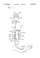
- FIG. 1is an elevational view of a parenteral fluid delivery system showing an inverted parenteral fluid container connected to a parenteral fluid administration set, the set being connected to an infusion pumping system including an air-in-line sensing apparatus of the invention;
- FIG. 2is an enlarged perspective view of the air-in-line sensing apparatus shown in FIG. 1 depicting a fluid administration conduit in a receiving position between first and second housings of the air-in-line sensing apparatus in accordance with the invention;
- FIG. 3is an enlarged top view of the first housing of the air-in-line sensing apparatus shown in FIG. 2;
- FIG. 4is a cross-sectional side view of the first housing of the air-in-line sensing apparatus taken along line 4--4 of FIG. 3;
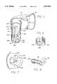
- FIG. 5is a perspective view of a second housing and its shaft having a snap fit feature for receiving a helical gear segment
- FIG. 6is a perspective view of a helical gear segment usable with the shaft of the second housing of FIG. 5 and usable with the snap fit feature of that shaft;
- FIG. 7is a top view of the helical gear segment of FIG. 6 more clearly showing the tongue used in the snap fit feature of FIG. 5;
- FIG. 8is an assembled view of the housing and shaft of FIG. 5 with the helical gear segment of FIG. 6;
- FIG. 9is an enlarged bottom view of the second housing of the air-in-line sensing apparatus shown in FIG. 2;
- FIG. 10is a side view of the second housing of the air-in-line sensing apparatus shown in FIG. 9;
- FIG. 11is a side view of the first and second housings of the air-in-line sensing apparatus of FIG. 2, illustrating such housing in an operatively closed position engaging the fluid conduit therebetween;
- FIG. 12is a cutaway view of a mechanism usable with the second housing to control the position of the second housing.
- FIG. 1there is shown a parenteral fluid intravenous infusion system 10 including an administration set 12 in fluid communication with an inverted parenteral fluid container 14.
- the infusion systemincludes an air-in-line sensing apparatus 15 in accordance with principles of the present invention.
- the inverted parenteral fluid container 14has a bottle shaped reservoir 14 including a hook mechanism 18 on the bottom end thereof connected to support rod 20 of a stand (not shown).
- the bottle reservoirhas a reduced diameter neck 22 having a stopper 24 disposed therein.
- the administration set 12comprises a fluid conduit, such as a length of flexible and compressible polyvinyl chloride (“PVC") tubing 26, the top end thereof connected to a vented penetrant 28.
- PVCpolyvinyl chloride
- the vented penetranthas a fluid bore therethrough, the top end thereof converging to a sharpened point. As shown in FIG. 1, the vented penetrant 28 has been inserted through the stopper 24 of the parenteral fluid container 14 so that the top end thereof is placed in fluid communication with parenteral fluid 30 contained in the reservoir 14.
- the free end of the administration set tubing 26is connected to an infusion cannula 32, the cannula attached to the free end of the tubing at a needle hub 34.
- the distal end of the infusion cannulais introduced into a blood vessel of a patient 36 for administration of the parenteral fluid to the patient.
- a fluid flow control devicesuch as a volumetric infusion pump 38, may be utilized to regulate the flow rate of parenteral fluid through the administration set.
- a volumetric infusion pump 38may be utilized to regulate the flow rate of parenteral fluid through the administration set.
- One such type of infusion pumpmay be, for instance, a linear peristaltic pump 38, and is shown for purposes of illustration.
- Linear type peristaltic pumpstypically include a pump housing 40 having a front panel 42 that includes controls, displays (not shown) and a mounting system for the fluid conduit 26.
- the administration set 12includes a dedicated pumping segment 43 (shown in dashed lines) that is engaged by the plurality of peristaltic pumping fingers 44.
- the peristaltic pumpwhen actuated, causes the pumping fingers to sequentially occlude adjacent segments of the pumping segment in a wave-like motion to force fluid through the tubing and to the patient.
- a tubing locking mechanism 46is vertically aligned above the pumping fingers 44.
- the air-in-line sensing apparatus 15 of the inventionis disposed downstream from the pumping fingers 44 and is mounted to the front panel 42 of the pump housing 40.
- the pumping segment 43 of the administration set tubing 26is operatively engaged with the peristaltic mechanism 44 between the tubing locking mechanism 46 and the air-in-line sensing apparatus 15.
- the air-in-line sensing apparatusis in its operative position wherein the tubing 26 is aligned properly in the sensing apparatus.
- a generally half-dome shaped member 47is disposed adjacent the air-in-line sensing transducers to assist in guiding the tubing into the correct position between the transducers.
- the air-in-line sensing apparatus 15in accordance with the invention will be described in detail.
- the air-in-line sensing apparatusincludes first and second housings, generally indicated at 50 and 52 respectively.
- the housingsare formed independently of one another and the second housing is independently movable relative to the first housing.
- the first housing 50is generally formed as a hollow open cylinder having vertically extending side walls 56 extending up to a top end 58.
- the bottom end of the open cylinderhas a pair of outwardly extending oppositely projecting mounting ears 60.
- the upper surface of the upper wall of the first housingis formed with a generally smooth horizontal planar upper surface 62 transitioning to a raised ridge 64 also having a generally horizontal planar top surface, the transition being formed transverse to the long axis of the cylinder and slightly off the axial centerline thereof to define first arcuate portion 66.
- the first arcuate portionmay be generally characterized as a smooth concave fillet formed between a ninety degree step transition from the smooth planar surface 62 to the raised ridge 64.
- the first arcuate portion 66is formed, on end, as a ninety degree radiused circular sector.
- a first transducer 68is fixedly secured to the bottom surface of top 58 of the first housing 50.
- the transduceris an ultrasonic transducer of a type well known in the art.
- the transduceris in the form of a rectangle, sized to conform to features on the inside of the cylindrical side walls 56 of first housing.
- the transducermay include a piezoelectric crystal 70 bonded to the bottom surface of the upper surface by an epoxy 72. The epoxy thickness is carefully controlled to ensure acoustic energy transfer from the piezoelectric crystal to the housing.
- a pair of electrical leads 74 and 76are attached to the opposite sides of the piezoelectric crystal and are directed out of the cylinder for connection to electronic equipment used to analyze the acoustical signals received by the piezoelectric crystal.
- the transducer of the first housing 50receives the ultrasonic signal.
- the opposite arrangementis also possible; i.e., where the transducer of the second housing 52 receives the ultrasonic signal transmitted by the transducer of the first housing.
- the first housing of the air-in-line sensing apparatusis composed of a polymeric material, such as ABS, and is formed as one piece by an injection molding process or the like to provide a single unitary body. Additionally, a recess 73 is formed around the first housing to receive a seal (not shown) when mounted to the front panel. The seal will prevent fluids from entering into the interior of the pump.
- the second housing 52is formed generally with a contoured upper portion 80 having forward, rearward and front ends, 82, 84 and 85 respectively, and a hollow shaft 86 projecting downward from the rearward end 84 of the upper portion.
- the front forward end 82 of the second housingfurther includes an outwardly projecting hook portion 87.
- the upper portion 80is generally hollow and includes a complementary formed cap 88 to enclose electrical components, described below.
- the shaftis generally an elongated hollow cylinder having a reduced-in-diameter step 90 extending downward therefrom to the bottom end 92 of the shaft to define a reduced-in-diameter cylindrical portion 91.
- the shaft 86has a helical gear segment 152 mounted to it to for effecting rotation of the second housing 52 to move the housing 52 into and out of operational position over the first housing 50.
- the shaft 86includes a pair of slots 150 spaced apart arcuately. These slots are used to provide surfaces to engage the helical gear segment 152 to receive rotational forces received by that gear segment to the shaft.
- a snap fit member 154 lying between the slotsremains as part of the shaft and is flexible.
- the snap fit member 154includes an aperture 156 in which a rigid tongue 158 of the helical gear segment is received.
- the tongue 158 of the helical gear 152causes the bendable snap fit member 154 to bend inward until the tongue reaches the aperture 156.
- the tongue 158then enters the aperture and the snap fit member 154 flexes back to its normal position thus locking the tongue of the helical gear in the aperture and locking the helical gear segment 152 to the shaft 86.
- This structureenables quick connect and disconnect of the helical gear segment with the shaft. To disconnect, the user manually bends the snap fit member 154 inward until the tongue is free of the edge of the aperture and then slides the helical gear segment off the shaft.
- the slots 150 in the shaft 86are shaped to form angular wedges 162 on the shaft. These angular wedges mate with complementary angular wedges 164 on the helical gear segment 152 when the two are assembled together as shown in FIG. 8.
- the wedges 162 and the portion of the shaft connecting themare the load-bearing portions of the shaft that receive the forces transmitted by the helical gear segment 152. Because the aperture and the tongue are located opposite the load bearing portion, the snap fit of the tongue into the aperture will not become disengaged by itself as a result of the transmission of rotational force through the helical gear segment 152. A manual bending of the flexible portion 154 inward will be required to separate the tongue 158 from the aperture 156.
- the configuration of the load-bearing portion of the shaftappears as a "C" and in this embodiment extends over an angle greater than one-hundred and eighty degrees.
- the wedgeshave an included angle of 100 degrees and are angled in relation to radii of the opening of the gear 152 for receiving the shaft.
- the combination of the angular wedges 162 and 164, the C shape and the extent of the load-bearing angledecouples the rotational forces from the snap fit feature so that the snap fit of the helical gear segment with the shaft remains intact over all design loads.
- FIG. 5Also shown in FIG. 5 is a channel 166 formed in the material of the shaft 86 for receiving the electrical wires (not shown) of the transducer in the second housing 52.
- This channelis formed in the end 92 of the shaft because the snap fit member 154 may be bent inward far enough to contact the inside surface of the load-bearing member 166. Thus the electrical wires are removed from possible contact with the member 154 during assembly and any disassembly that may occur.
- the cap 88is complementarily contoured for mating the bottom peripheral edge thereof to the upper portion 80 of the second housing 52. As illustrated, the top surface of the cap is slightly domed.
- the second housing 52is described in more detail.
- the cap 88 of the second housinghas been removed and is not shown.
- the upper portion 80 of the second housingmay be generally considered rectangular in shape having a shallow upstanding side wall 96 around the periphery thereof.
- the shaft 86is formed at the rearward end 84 extending downwardly from upper portion 80 so that the cylindrical hollow of the shaft is accessible from the upper portion.
- the bottom surface 98 of the upper portion 80 of the second housing 52has a generally smooth planar horizontal section transitioning to a raised smooth horizontal planar surface section or shelf 100 at the forward end 82 of the upper portion.
- the transitionis formed transverse to the longitudinal extent of the upper portion to define a second arcuate portion 102.
- the second arcuate portion 102may be generally characterized as a smooth concave fillet formed between a ninety degree step transition from the bottom planar surface 98 to the planar shelf 100.
- the second arcuate portionis formed, on end, as a ninety degree radiused circular sector.
- the second arcuate portion 102is formed with an arcuate tapered flare 104 that tapers and curves in two dimensions, rearwardly and upwardly to the front end 85 of the upper portion 80 of the second housing 52 beneath the projecting hook 87.
- the second housing 52 of the air-in-line sensing apparatuscomprises a polymeric material, such as ABS, and is formed as one piece by an injection molding process or the like to provide a unitary body.
- a second transducer 106is located within the upper portion 80 of the second housing 52 and is positioned atop the planar shelf 100 at the forward end 82 of the second housing.
- the second transduceris an ultrasonic transducer of a type well known in the art.
- the second transduceris in the form of a flat thin rectangular plate, the longitudinal length thereof positioned in parallel alignment generally adjacent and above the second arcuate portion 102 of the second housing.
- the second transducermay include a piezoelectric crystal 106 bonded to the surface above the planar shelf 100 by an epoxy 107.
- the epoxy and polymer that it is bonded tomay serve as an acoustical lens to focus acoustic energy from the bottom surface of the piezoelectric crystal to the outside surface of the housing.
- the pair of electrical leads 108 and 110are affixed to the respective upper and lower faces of the piezoelectric crystal 107, the free ends thereof being received through the hollow of the shaft 86 and connected to electrical equipment for exciting the piezoelectric crystal to transmit acoustical energy.
- the air-in-line sensing apparatus 15may be used in conjunction with a fluid infusion pumping system, and is shown for purposes of illustration mounted to a peristaltic type pumping system 38 (FIG. 1).
- the first and second housings, 50 and 52, of the air-in-line sensing apparatusare mounted to the front panel 42 of the pump housing 40. In its unactuated tubing receiving position, the upper portion 80 of the second housing 52 of the air-in-line sensing apparatus 15 is oriented in a vertical upwardly predisposed position.
- the second housingWhen the air-in-line sensing device is in its operatively closed position, the second housing is rotated, from its vertical upward position, approximately one-quarter turn in a clockwise direction to capture and compress the administration set tubing 12 between the respective first arcuate portion 66 of the first housing 50 and second arcuate portion 102 of the second housing 52 as illustrated in FIG. 11.
- the front panel 42is formed with a first bore 109 therethrough for slidable receipt of the cylindrical first housing 50 from the back side, the mounting tabs or ears 60 biased by a compression spring 111 to abut the back surface of the front panel. Due to the compressive force of spring 111, the first housing 50 is biased toward the second housing 52. However, the presence of the tubing 12 typically results in the first housing 50 being forced somewhat into the front panel as shown in FIG. 11. With no tubing in place, the first housing 50 would be “bottomed out” against the front panel due to the force of the compression spring 111. That is, the mounting tabs 60 would make contact with the back of the front panel to stop the first housing 50 from being pressed through the front panel by the spring 111.
- tubing 26, positioned between first arcuate section 66 and second arcuate section 102,is slightly compressed, which ensures that both transducers are covered by the compressed tubing and thus will sense no external air to cause false or inaccurate readings. Furthermore, it has been noted that the tubing has a tendency to deform under slight compression over extended periods of time.
- the spring biasing of the first housing relative to the second housingensures that the respective arcuate sections 66 and 102 and respective planar surfaces 62 and 100 maintain intimate contact with the tubing even if such tubing has deformed.
- a second bore 112is formed through the front panel for slidable receipt of the shaft 86 of the second housing 52.
- the shaftis slidably received within the second bore from the front surface of the front panel so that the bottom end 92 of the shaft extends into the pump housing.
- the shaftis rotatably mounted therein by means well known in the art, for instance by a spring clip or the like.
- a rotational mechanism 170 for rotating the second housing 52 into and out of operational positionis illustrated.
- a latch lever 172is provided for manually causing the rotation.
- the distal end of the latch leveris connected via ring gear 174 with another gear 176 mounted firmly to the end of a driving shaft 178. Movement of the latch lever 172 thus causes rotation of the driving shaft 178.
- a second gear 180At the opposite end of the driving shaft 178 is a second gear 180.
- the helical gear segment 152is coupled to this second gear and transmits the rotation movement of the second gear 180 to the shaft 86 of the second housing 52.
- movement of the latch lever 172causes rotation of the second gear which in turn causes rotation of the second housing 52.
- the driving shaft 178is also shown connected to a clamp system 182 that may be used to firmly grasp a pumping segment (not shown) to the front panel 184. Rotation of the latch lever 172 will therefore cause both the clamp to engage a pumping segment as well as bring the second housing 52 into operational position over the pumping segment to sense air in the line.
- the second housing 52 of the air-in-line sensing apparatus 15may be rotatably actuated by the user by simply rotating the second housing relative to the first housing 52 manually, whereby a releasable locking means, well known to those skilled in the art, may be incorporated therewith to lock the second housing relative to the first housing.
- the guide member 47is mounted to the front surface of the front panel 42 of the pump housing and is positioned so that when the second housing is in its operative position, the forward end 82 of the second housing is positioned in a closely spaced relationship adjacent the guide member 47.
- the guide memberis generally formed as a solid half dome having an inwardly depressed quarter-spherical surface 114, the upper outer peripheral edge 116 of the half-dome being inwardly curved.
- the second housing 52 of the air-in-line sensing apparatus 15would be in its vertical (upright) open tubing-receiving position, shown in dashed lines in FIG. 1.
- the pumping segment 43 of the administration set tubing 26is placed into position over the pumping fingers 44 of the pumping mechanism and a segment of the tubing is disposed within an aperture in the tubing locking mechanism 46.
- the flexible administration set tubing 26is placed over the planar surface 62 of the first housing 50 generally adjacent the first arcuate portion 66 thereof.
- the tubing 26may not be longitudinally straight, as shown, because tubing is typically coiled in packaging for shipping. Therefore, when the tubing is uncoiled, there may be bends in the tubing when installed in the air-in-line sensing apparatus 15 which may cause segments of the tubing to be spaced apart from the upper surface 62 or from the first arcuate portion 66 of the first housing.
- the second housing 52is rotated approximately one quarter turn in a clockwise direction from a vertically upright position to a generally horizontal position. If the tubing is bent in a direction toward the guide member 47, the guide member confronts the tubing to hold the tubing to limit it from moving farther away from the first housing as the second housing is rotated into position. The guide member 47 also assists in bringing the tubing into alignment between the first and second housings. If the tubing is bent outwardly from the front panel 42, the projecting hook 87 of the second housing will hook and urge the tubing downward into alignment between the first and second housings as the second housing is rotated. Furthermore, if the tubing is bent in a direction toward the second housing, such second housing confronts the tubing to maintain the tubing in such position so that the second housing, when rotated, captures the tubing between the first and second housings, as described in detail below.
- the upper slanted surface 105 of arcuate tapered flare 104slidably engages the tubing 26 to urge such tubing downward against the upper surface 62 of the first housing 50.
- the downwardly extending surface 107 of the arcuate tapered flare 104slidably engages the side wall of the tubing to urge such tubing horizontally toward the first arcuate portion 66 of the first housing.
- the tubing 12is urged into parallel alignment between the first and second arcuate portions 66, 102 as the second housing is rotated to its horizontal closed position, whereby the first and second arcuate portions come into parallel alignment with each other providing, in essence, an automatic tube-loading feature.
- arcuate tapered flare 104slides along the outer surface of the conduit to sweep and clean debris and fluid therefrom which may have collected on the surface thereof.
- the clean surface of the tubingallows for more accurate acoustical signal transmission through the tubing 26 and fluid carried therein.
- the arcuate portions, 66 and 102slightly compress the walls of the tubing 26 inwardly so that intimate positive contact is insured between the respective arcuate portions of the housings and the tubing while minimizing tubing distortion. It is important that such intimate contact be provided, because if air is trapped between the tubing and the arcuate portions, inaccurate or false readings may be incurred due to the transducers effectively sensing such air and not being able to distinguish air outside the tubing from air in the fluid carried in the tubing. Such contact improves ultrasonic signal strength and therefore improves the signal-to-noise ratio of the transducers.
- the parallel alignment and the selected spaced-apart configuration of the arcuate portions 66 and 102, as well as the spring loadingprovide such intimate contact over extended durations.
- the spring loading of one of the housingsprovides compensation for reduced tubing size in the case where the tubing is pulled axially.
- the spring 111will automatically cause the first housing 50 to continue to make good contact with the reduced-diameter tubing.
- an air-in-line sensing apparatus constructed in accordance with the inventionmay be incorporated in other types of fluid administration sets and other types of fluid infusion devices.
- the apparatusmay be used in the case where a syringe pump provides the force to move the fluid through the conduit.
Landscapes
- Health & Medical Sciences (AREA)
- Physics & Mathematics (AREA)
- Life Sciences & Earth Sciences (AREA)
- General Health & Medical Sciences (AREA)
- Chemical & Material Sciences (AREA)
- Analytical Chemistry (AREA)
- Biochemistry (AREA)
- General Physics & Mathematics (AREA)
- Immunology (AREA)
- Pathology (AREA)
- Acoustics & Sound (AREA)
- Anesthesiology (AREA)
- Veterinary Medicine (AREA)
- Engineering & Computer Science (AREA)
- Emergency Medicine (AREA)
- Biomedical Technology (AREA)
- Heart & Thoracic Surgery (AREA)
- Hematology (AREA)
- Animal Behavior & Ethology (AREA)
- Public Health (AREA)
- Vascular Medicine (AREA)
- Infusion, Injection, And Reservoir Apparatuses (AREA)
- Investigating Or Analyzing Materials By The Use Of Ultrasonic Waves (AREA)
- Fire-Detection Mechanisms (AREA)
- Investigating Or Analyzing Materials By The Use Of Electric Means (AREA)
- Crystals, And After-Treatments Of Crystals (AREA)
- Measurement Of Radiation (AREA)
- External Artificial Organs (AREA)
Abstract
Description
Claims (41)
Priority Applications (10)
| Application Number | Priority Date | Filing Date | Title |
|---|---|---|---|
| US08/305,466US5537853A (en) | 1994-09-12 | 1994-09-12 | Air-in-line sensing apparatus |
| GR990300030TGR990300030T1 (en) | 1994-09-12 | 1995-09-08 | Air-in-line sensing apparatus |
| DE0809802TDE809802T1 (en) | 1994-09-12 | 1995-09-08 | BUBBLE MEASURING DEVICE |
| AT95932432TATE256285T1 (en) | 1994-09-12 | 1995-09-08 | AIR BUBBLES MEASUREMENT DEVICE |
| CA002199157ACA2199157C (en) | 1994-09-12 | 1995-09-08 | Air-in-line sensing apparatus |
| JP51024596AJP3401259B2 (en) | 1994-09-12 | 1995-09-08 | Air-in-line detector |
| ES95932432TES2135357T3 (en) | 1994-09-12 | 1995-09-08 | AIR DETECTOR APPLIANCE IN A DUCT. |
| DE69532301TDE69532301T2 (en) | 1994-09-12 | 1995-09-08 | BUBBLE MEASURING DEVICE |
| EP95932432AEP0809802B1 (en) | 1994-09-12 | 1995-09-08 | Air-in-line sensing apparatus |
| PCT/US1995/011358WO1996008717A1 (en) | 1994-09-12 | 1995-09-08 | Air-in-line sensing apparatus |
Applications Claiming Priority (1)
| Application Number | Priority Date | Filing Date | Title |
|---|---|---|---|
| US08/305,466US5537853A (en) | 1994-09-12 | 1994-09-12 | Air-in-line sensing apparatus |
Publications (1)
| Publication Number | Publication Date |
|---|---|
| US5537853Atrue US5537853A (en) | 1996-07-23 |
Family
ID=23180919
Family Applications (1)
| Application Number | Title | Priority Date | Filing Date |
|---|---|---|---|
| US08/305,466Expired - LifetimeUS5537853A (en) | 1994-09-12 | 1994-09-12 | Air-in-line sensing apparatus |
Country Status (9)
| Country | Link |
|---|---|
| US (1) | US5537853A (en) |
| EP (1) | EP0809802B1 (en) |
| JP (1) | JP3401259B2 (en) |
| AT (1) | ATE256285T1 (en) |
| CA (1) | CA2199157C (en) |
| DE (2) | DE809802T1 (en) |
| ES (1) | ES2135357T3 (en) |
| GR (1) | GR990300030T1 (en) |
| WO (1) | WO1996008717A1 (en) |
Cited By (52)
| Publication number | Priority date | Publication date | Assignee | Title |
|---|---|---|---|---|
| US6142008A (en)* | 1998-06-12 | 2000-11-07 | Abbott Laboratories | Air bubble sensor |
| US6231320B1 (en) | 1998-06-12 | 2001-05-15 | Abbott Laboratories | Drug infusion pumping cassette latching mechanism |
| WO2002074362A3 (en)* | 2001-03-16 | 2002-11-14 | Vasogen Ireland Ltd | Apparatus and process for conditioning and de-bubbling organic fluid |
| US6489896B1 (en)* | 2000-11-03 | 2002-12-03 | Baxter International Inc. | Air in-line sensor for ambulatory drug infusion pump |
| US6616633B1 (en)* | 1997-09-19 | 2003-09-09 | Alaris Medical Systems, Inc. | Apparatus and method for air-in-line detection |
| US6985870B2 (en) | 2002-01-11 | 2006-01-10 | Baxter International Inc. | Medication delivery system |
| US20100141460A1 (en)* | 2008-12-08 | 2010-06-10 | Ecolab Inc. | Acoustic fluid presence/absence detection |
| US7934912B2 (en) | 2007-09-27 | 2011-05-03 | Curlin Medical Inc | Peristaltic pump assembly with cassette and mounting pin arrangement |
| US8033157B2 (en) | 2007-10-01 | 2011-10-11 | Baxter International Inc. | Medical fluid air bubble detection apparatus and method |
| US8062008B2 (en) | 2007-09-27 | 2011-11-22 | Curlin Medical Inc. | Peristaltic pump and removable cassette therefor |
| US8083503B2 (en) | 2007-09-27 | 2011-12-27 | Curlin Medical Inc. | Peristaltic pump assembly and regulator therefor |
| US8091442B1 (en)* | 2008-04-19 | 2012-01-10 | Cosense, Inc. | Positive tube retention arrangement |
| US8234128B2 (en) | 2002-04-30 | 2012-07-31 | Baxter International, Inc. | System and method for verifying medical device operational parameters |
| US20130091953A1 (en)* | 2011-10-17 | 2013-04-18 | Houston Brown | Air in line detector with loading enhancements |
| US8775196B2 (en) | 2002-01-29 | 2014-07-08 | Baxter International Inc. | System and method for notification and escalation of medical data |
| US20160370212A1 (en)* | 2015-06-17 | 2016-12-22 | Berkeley Springs Instruments Llc | Transducer mounting apparatus |
| WO2017160739A1 (en)* | 2016-03-14 | 2017-09-21 | Pendo TECH | Processing system for multiple tangential flow filtration stations in bioprocessing applications |
| US9995611B2 (en) | 2012-03-30 | 2018-06-12 | Icu Medical, Inc. | Air detection system and method for detecting air in a pump of an infusion system |
| US10016554B2 (en) | 2008-07-09 | 2018-07-10 | Baxter International Inc. | Dialysis system including wireless patient data |
| US10022498B2 (en) | 2011-12-16 | 2018-07-17 | Icu Medical, Inc. | System for monitoring and delivering medication to a patient and method of using the same to minimize the risks associated with automated therapy |
| US10046112B2 (en) | 2013-05-24 | 2018-08-14 | Icu Medical, Inc. | Multi-sensor infusion system for detecting air or an occlusion in the infusion system |
| US10061899B2 (en) | 2008-07-09 | 2018-08-28 | Baxter International Inc. | Home therapy machine |
| US10166328B2 (en) | 2013-05-29 | 2019-01-01 | Icu Medical, Inc. | Infusion system which utilizes one or more sensors and additional information to make an air determination regarding the infusion system |
| US10173008B2 (en) | 2002-01-29 | 2019-01-08 | Baxter International Inc. | System and method for communicating with a dialysis machine through a network |
| US10342917B2 (en) | 2014-02-28 | 2019-07-09 | Icu Medical, Inc. | Infusion system and method which utilizes dual wavelength optical air-in-line detection |
| US10347374B2 (en) | 2008-10-13 | 2019-07-09 | Baxter Corporation Englewood | Medication preparation system |
| US10430761B2 (en) | 2011-08-19 | 2019-10-01 | Icu Medical, Inc. | Systems and methods for a graphical interface including a graphical representation of medical data |
| US10463788B2 (en) | 2012-07-31 | 2019-11-05 | Icu Medical, Inc. | Patient care system for critical medications |
| US10552577B2 (en) | 2012-08-31 | 2020-02-04 | Baxter Corporation Englewood | Medication requisition fulfillment system and method |
| US10596316B2 (en) | 2013-05-29 | 2020-03-24 | Icu Medical, Inc. | Infusion system and method of use which prevents over-saturation of an analog-to-digital converter |
| US10635784B2 (en) | 2007-12-18 | 2020-04-28 | Icu Medical, Inc. | User interface improvements for medical devices |
| US10646405B2 (en) | 2012-10-26 | 2020-05-12 | Baxter Corporation Englewood | Work station for medical dose preparation system |
| US10656894B2 (en) | 2017-12-27 | 2020-05-19 | Icu Medical, Inc. | Synchronized display of screen content on networked devices |
| US10818387B2 (en) | 2014-12-05 | 2020-10-27 | Baxter Corporation Englewood | Dose preparation data analytics |
| US10850024B2 (en) | 2015-03-02 | 2020-12-01 | Icu Medical, Inc. | Infusion system, device, and method having advanced infusion features |
| US10971257B2 (en) | 2012-10-26 | 2021-04-06 | Baxter Corporation Englewood | Image acquisition for medical dose preparation system |
| US11107574B2 (en) | 2014-09-30 | 2021-08-31 | Baxter Corporation Englewood | Management of medication preparation with formulary management |
| US11135360B1 (en) | 2020-12-07 | 2021-10-05 | Icu Medical, Inc. | Concurrent infusion with common line auto flush |
| US11246985B2 (en) | 2016-05-13 | 2022-02-15 | Icu Medical, Inc. | Infusion pump system and method with common line auto flush |
| US11278671B2 (en) | 2019-12-04 | 2022-03-22 | Icu Medical, Inc. | Infusion pump with safety sequence keypad |
| US11324888B2 (en) | 2016-06-10 | 2022-05-10 | Icu Medical, Inc. | Acoustic flow sensor for continuous medication flow measurements and feedback control of infusion |
| US11344668B2 (en) | 2014-12-19 | 2022-05-31 | Icu Medical, Inc. | Infusion system with concurrent TPN/insulin infusion |
| US11344673B2 (en) | 2014-05-29 | 2022-05-31 | Icu Medical, Inc. | Infusion system and pump with configurable closed loop delivery rate catch-up |
| US11367533B2 (en) | 2014-06-30 | 2022-06-21 | Baxter Corporation Englewood | Managed medical information exchange |
| US11495334B2 (en) | 2015-06-25 | 2022-11-08 | Gambro Lundia Ab | Medical device system and method having a distributed database |
| US11516183B2 (en) | 2016-12-21 | 2022-11-29 | Gambro Lundia Ab | Medical device system including information technology infrastructure having secure cluster domain supporting external domain |
| US11575673B2 (en) | 2014-09-30 | 2023-02-07 | Baxter Corporation Englewood | Central user management in a distributed healthcare information management system |
| US11883361B2 (en) | 2020-07-21 | 2024-01-30 | Icu Medical, Inc. | Fluid transfer devices and methods of use |
| US11948112B2 (en) | 2015-03-03 | 2024-04-02 | Baxter Corporation Engelwood | Pharmacy workflow management with integrated alerts |
| US12350233B2 (en) | 2021-12-10 | 2025-07-08 | Icu Medical, Inc. | Medical fluid compounding systems with coordinated flow control |
| USD1091564S1 (en) | 2021-10-13 | 2025-09-02 | Icu Medical, Inc. | Display screen or portion thereof with graphical user interface for a medical device |
| US12412644B2 (en) | 2014-10-24 | 2025-09-09 | Baxter Corporation Englewood | Automated exchange of healthcare information for fulfillment of medication doses |
Families Citing this family (2)
| Publication number | Priority date | Publication date | Assignee | Title |
|---|---|---|---|---|
| DE4137606C1 (en)* | 1991-11-15 | 1992-07-30 | Schott Glaswerke, 6500 Mainz, De | |
| JP6855300B2 (en)* | 2017-03-28 | 2021-04-07 | テルモ株式会社 | How to clean the outer surface of the infusion pump and tube |
Citations (7)
| Publication number | Priority date | Publication date | Assignee | Title |
|---|---|---|---|---|
| US3171273A (en)* | 1961-07-31 | 1965-03-02 | Heineken S Brouwerijen Nederla | Method of establishing the gas equilibrium pressure in an aqueous liquid |
| US3182487A (en)* | 1962-08-03 | 1965-05-11 | Frank O Graham | Testing for volume of soluble gases |
| US3225585A (en)* | 1963-02-28 | 1965-12-28 | Lockheed Aircraft Corp | Method and apparatus for measuring air in hydraulic systems |
| US3486370A (en)* | 1966-02-22 | 1969-12-30 | Commissariat Energie Atomique | Method and device for measuring the gas content of a flowing two-phase mixture |
| US3974681A (en)* | 1973-10-23 | 1976-08-17 | Jerry Namery | Ultrasonic bubble detector |
| US4418565A (en)* | 1980-12-03 | 1983-12-06 | Baxter Travenol Laboratories, Inc. | Ultrasonic bubble detector |
| US5394732A (en)* | 1993-09-10 | 1995-03-07 | Cobe Laboratories, Inc. | Method and apparatus for ultrasonic detection of air bubbles |
Family Cites Families (3)
| Publication number | Priority date | Publication date | Assignee | Title |
|---|---|---|---|---|
| US4312341A (en)* | 1979-12-13 | 1982-01-26 | Baxter Travenol Laboratories, Inc. | Bubble detector |
| US5123275A (en)* | 1990-12-07 | 1992-06-23 | Ivac Corporation | Air in-line sensor system |
| US5177993A (en) | 1991-07-22 | 1993-01-12 | Ivac Corporation | Air-in-line sensor |
- 1994
- 1994-09-12USUS08/305,466patent/US5537853A/ennot_activeExpired - Lifetime
- 1995
- 1995-09-08WOPCT/US1995/011358patent/WO1996008717A1/enactiveIP Right Grant
- 1995-09-08CACA002199157Apatent/CA2199157C/ennot_activeExpired - Fee Related
- 1995-09-08JPJP51024596Apatent/JP3401259B2/ennot_activeExpired - Lifetime
- 1995-09-08ATAT95932432Tpatent/ATE256285T1/ennot_activeIP Right Cessation
- 1995-09-08DEDE0809802Tpatent/DE809802T1/enactivePending
- 1995-09-08EPEP95932432Apatent/EP0809802B1/ennot_activeExpired - Lifetime
- 1995-09-08ESES95932432Tpatent/ES2135357T3/ennot_activeExpired - Lifetime
- 1995-09-08GRGR990300030Tpatent/GR990300030T1/enunknown
- 1995-09-08DEDE69532301Tpatent/DE69532301T2/ennot_activeExpired - Lifetime
Patent Citations (7)
| Publication number | Priority date | Publication date | Assignee | Title |
|---|---|---|---|---|
| US3171273A (en)* | 1961-07-31 | 1965-03-02 | Heineken S Brouwerijen Nederla | Method of establishing the gas equilibrium pressure in an aqueous liquid |
| US3182487A (en)* | 1962-08-03 | 1965-05-11 | Frank O Graham | Testing for volume of soluble gases |
| US3225585A (en)* | 1963-02-28 | 1965-12-28 | Lockheed Aircraft Corp | Method and apparatus for measuring air in hydraulic systems |
| US3486370A (en)* | 1966-02-22 | 1969-12-30 | Commissariat Energie Atomique | Method and device for measuring the gas content of a flowing two-phase mixture |
| US3974681A (en)* | 1973-10-23 | 1976-08-17 | Jerry Namery | Ultrasonic bubble detector |
| US4418565A (en)* | 1980-12-03 | 1983-12-06 | Baxter Travenol Laboratories, Inc. | Ultrasonic bubble detector |
| US5394732A (en)* | 1993-09-10 | 1995-03-07 | Cobe Laboratories, Inc. | Method and apparatus for ultrasonic detection of air bubbles |
Cited By (94)
| Publication number | Priority date | Publication date | Assignee | Title |
|---|---|---|---|---|
| US7141037B2 (en) | 1997-09-19 | 2006-11-28 | Cardinal Health 303, Inc. | Apparatus and method for air-in-line detection |
| US8082112B2 (en) | 1997-09-19 | 2011-12-20 | Carefusion 303, Inc. | Apparatus and method for air-in-line detection |
| US6616633B1 (en)* | 1997-09-19 | 2003-09-09 | Alaris Medical Systems, Inc. | Apparatus and method for air-in-line detection |
| US20050192529A1 (en)* | 1997-09-19 | 2005-09-01 | Butterfield Robert D. | Apparatus and method for air-in-line detection |
| US20080208484A1 (en)* | 1997-09-19 | 2008-08-28 | Cardinal Health 303, Inc. | Apparatus and method for air-in-line detection |
| US6231320B1 (en) | 1998-06-12 | 2001-05-15 | Abbott Laboratories | Drug infusion pumping cassette latching mechanism |
| US6142008A (en)* | 1998-06-12 | 2000-11-07 | Abbott Laboratories | Air bubble sensor |
| US6802892B2 (en) | 1999-09-16 | 2004-10-12 | Vasogen Ireland Limited | Apparatus and process for conditioning organic fluid |
| US6489896B1 (en)* | 2000-11-03 | 2002-12-03 | Baxter International Inc. | Air in-line sensor for ambulatory drug infusion pump |
| AU2002242529B2 (en)* | 2001-03-16 | 2006-12-14 | Vasogen Ireland Limited | Apparatus and process for conditioning and de-bubbling organic fluid |
| WO2002074362A3 (en)* | 2001-03-16 | 2002-11-14 | Vasogen Ireland Ltd | Apparatus and process for conditioning and de-bubbling organic fluid |
| US6985870B2 (en) | 2002-01-11 | 2006-01-10 | Baxter International Inc. | Medication delivery system |
| US7668731B2 (en) | 2002-01-11 | 2010-02-23 | Baxter International Inc. | Medication delivery system |
| US8775196B2 (en) | 2002-01-29 | 2014-07-08 | Baxter International Inc. | System and method for notification and escalation of medical data |
| US10556062B2 (en) | 2002-01-29 | 2020-02-11 | Baxter International Inc. | Electronic medication order transfer and processing methods and apparatus |
| US10173008B2 (en) | 2002-01-29 | 2019-01-08 | Baxter International Inc. | System and method for communicating with a dialysis machine through a network |
| US8234128B2 (en) | 2002-04-30 | 2012-07-31 | Baxter International, Inc. | System and method for verifying medical device operational parameters |
| US8062008B2 (en) | 2007-09-27 | 2011-11-22 | Curlin Medical Inc. | Peristaltic pump and removable cassette therefor |
| US7934912B2 (en) | 2007-09-27 | 2011-05-03 | Curlin Medical Inc | Peristaltic pump assembly with cassette and mounting pin arrangement |
| US8083503B2 (en) | 2007-09-27 | 2011-12-27 | Curlin Medical Inc. | Peristaltic pump assembly and regulator therefor |
| US8033157B2 (en) | 2007-10-01 | 2011-10-11 | Baxter International Inc. | Medical fluid air bubble detection apparatus and method |
| US10635784B2 (en) | 2007-12-18 | 2020-04-28 | Icu Medical, Inc. | User interface improvements for medical devices |
| US8091442B1 (en)* | 2008-04-19 | 2012-01-10 | Cosense, Inc. | Positive tube retention arrangement |
| US10068061B2 (en) | 2008-07-09 | 2018-09-04 | Baxter International Inc. | Home therapy entry, modification, and reporting system |
| US10646634B2 (en) | 2008-07-09 | 2020-05-12 | Baxter International Inc. | Dialysis system and disposable set |
| US11918721B2 (en) | 2008-07-09 | 2024-03-05 | Baxter International Inc. | Dialysis system having adaptive prescription management |
| US10016554B2 (en) | 2008-07-09 | 2018-07-10 | Baxter International Inc. | Dialysis system including wireless patient data |
| US10272190B2 (en) | 2008-07-09 | 2019-04-30 | Baxter International Inc. | Renal therapy system including a blood pressure monitor |
| US11311658B2 (en) | 2008-07-09 | 2022-04-26 | Baxter International Inc. | Dialysis system having adaptive prescription generation |
| US10061899B2 (en) | 2008-07-09 | 2018-08-28 | Baxter International Inc. | Home therapy machine |
| US10224117B2 (en) | 2008-07-09 | 2019-03-05 | Baxter International Inc. | Home therapy machine allowing patient device program selection |
| US10095840B2 (en) | 2008-07-09 | 2018-10-09 | Baxter International Inc. | System and method for performing renal therapy at a home or dwelling of a patient |
| US10347374B2 (en) | 2008-10-13 | 2019-07-09 | Baxter Corporation Englewood | Medication preparation system |
| US8120500B2 (en) | 2008-12-08 | 2012-02-21 | Ecolab Inc. | Acoustic fluid presence/absence detection |
| US20100141460A1 (en)* | 2008-12-08 | 2010-06-10 | Ecolab Inc. | Acoustic fluid presence/absence detection |
| US12346879B2 (en) | 2011-08-19 | 2025-07-01 | Icu Medical, Inc. | Systems and methods for a graphical interface including a graphical representation of medical data |
| US10430761B2 (en) | 2011-08-19 | 2019-10-01 | Icu Medical, Inc. | Systems and methods for a graphical interface including a graphical representation of medical data |
| US11004035B2 (en) | 2011-08-19 | 2021-05-11 | Icu Medical, Inc. | Systems and methods for a graphical interface including a graphical representation of medical data |
| US11972395B2 (en) | 2011-08-19 | 2024-04-30 | Icu Medical, Inc. | Systems and methods for a graphical interface including a graphical representation of medical data |
| US11599854B2 (en) | 2011-08-19 | 2023-03-07 | Icu Medical, Inc. | Systems and methods for a graphical interface including a graphical representation of medical data |
| US20130091953A1 (en)* | 2011-10-17 | 2013-04-18 | Houston Brown | Air in line detector with loading enhancements |
| US10022498B2 (en) | 2011-12-16 | 2018-07-17 | Icu Medical, Inc. | System for monitoring and delivering medication to a patient and method of using the same to minimize the risks associated with automated therapy |
| US11376361B2 (en) | 2011-12-16 | 2022-07-05 | Icu Medical, Inc. | System for monitoring and delivering medication to a patient and method of using the same to minimize the risks associated with automated therapy |
| US9995611B2 (en) | 2012-03-30 | 2018-06-12 | Icu Medical, Inc. | Air detection system and method for detecting air in a pump of an infusion system |
| US11933650B2 (en) | 2012-03-30 | 2024-03-19 | Icu Medical, Inc. | Air detection system and method for detecting air in a pump of an infusion system |
| US10578474B2 (en) | 2012-03-30 | 2020-03-03 | Icu Medical, Inc. | Air detection system and method for detecting air in a pump of an infusion system |
| US10089443B2 (en) | 2012-05-15 | 2018-10-02 | Baxter International Inc. | Home medical device systems and methods for therapy prescription and tracking, servicing and inventory |
| US11623042B2 (en) | 2012-07-31 | 2023-04-11 | Icu Medical, Inc. | Patient care system for critical medications |
| US12280239B2 (en) | 2012-07-31 | 2025-04-22 | Icu Medical, Inc. | Patient care system for critical medications |
| US10463788B2 (en) | 2012-07-31 | 2019-11-05 | Icu Medical, Inc. | Patient care system for critical medications |
| US10552577B2 (en) | 2012-08-31 | 2020-02-04 | Baxter Corporation Englewood | Medication requisition fulfillment system and method |
| US10646405B2 (en) | 2012-10-26 | 2020-05-12 | Baxter Corporation Englewood | Work station for medical dose preparation system |
| US10971257B2 (en) | 2012-10-26 | 2021-04-06 | Baxter Corporation Englewood | Image acquisition for medical dose preparation system |
| US10046112B2 (en) | 2013-05-24 | 2018-08-14 | Icu Medical, Inc. | Multi-sensor infusion system for detecting air or an occlusion in the infusion system |
| US12048831B2 (en) | 2013-05-24 | 2024-07-30 | Icu Medical, Inc. | Multi-sensor infusion system for detecting air or an occlusion in the infusion system |
| US10874793B2 (en) | 2013-05-24 | 2020-12-29 | Icu Medical, Inc. | Multi-sensor infusion system for detecting air or an occlusion in the infusion system |
| US10596316B2 (en) | 2013-05-29 | 2020-03-24 | Icu Medical, Inc. | Infusion system and method of use which prevents over-saturation of an analog-to-digital converter |
| US11596737B2 (en) | 2013-05-29 | 2023-03-07 | Icu Medical, Inc. | Infusion system and method of use which prevents over-saturation of an analog-to-digital converter |
| US10166328B2 (en) | 2013-05-29 | 2019-01-01 | Icu Medical, Inc. | Infusion system which utilizes one or more sensors and additional information to make an air determination regarding the infusion system |
| US12059551B2 (en) | 2013-05-29 | 2024-08-13 | Icu Medical, Inc. | Infusion system and method of use which prevents over-saturation of an analog-to-digital converter |
| US11433177B2 (en) | 2013-05-29 | 2022-09-06 | Icu Medical, Inc. | Infusion system which utilizes one or more sensors and additional information to make an air determination regarding the infusion system |
| US10342917B2 (en) | 2014-02-28 | 2019-07-09 | Icu Medical, Inc. | Infusion system and method which utilizes dual wavelength optical air-in-line detection |
| US12083310B2 (en) | 2014-02-28 | 2024-09-10 | Icu Medical, Inc. | Infusion system and method which utilizes dual wavelength optical air-in-line detection |
| US11344673B2 (en) | 2014-05-29 | 2022-05-31 | Icu Medical, Inc. | Infusion system and pump with configurable closed loop delivery rate catch-up |
| US11367533B2 (en) | 2014-06-30 | 2022-06-21 | Baxter Corporation Englewood | Managed medical information exchange |
| US11575673B2 (en) | 2014-09-30 | 2023-02-07 | Baxter Corporation Englewood | Central user management in a distributed healthcare information management system |
| US11107574B2 (en) | 2014-09-30 | 2021-08-31 | Baxter Corporation Englewood | Management of medication preparation with formulary management |
| US12412644B2 (en) | 2014-10-24 | 2025-09-09 | Baxter Corporation Englewood | Automated exchange of healthcare information for fulfillment of medication doses |
| US10818387B2 (en) | 2014-12-05 | 2020-10-27 | Baxter Corporation Englewood | Dose preparation data analytics |
| US11344668B2 (en) | 2014-12-19 | 2022-05-31 | Icu Medical, Inc. | Infusion system with concurrent TPN/insulin infusion |
| US10850024B2 (en) | 2015-03-02 | 2020-12-01 | Icu Medical, Inc. | Infusion system, device, and method having advanced infusion features |
| US12115337B2 (en) | 2015-03-02 | 2024-10-15 | Icu Medical, Inc. | Infusion system, device, and method having advanced infusion features |
| US11948112B2 (en) | 2015-03-03 | 2024-04-02 | Baxter Corporation Engelwood | Pharmacy workflow management with integrated alerts |
| US20160370212A1 (en)* | 2015-06-17 | 2016-12-22 | Berkeley Springs Instruments Llc | Transducer mounting apparatus |
| US10782161B2 (en)* | 2015-06-17 | 2020-09-22 | Berkeley Springs Instruments, Llc | Ultrasonic transducer mounting apparatus for attaching a transducer block to a pipeline |
| US11495334B2 (en) | 2015-06-25 | 2022-11-08 | Gambro Lundia Ab | Medical device system and method having a distributed database |
| WO2017160739A1 (en)* | 2016-03-14 | 2017-09-21 | Pendo TECH | Processing system for multiple tangential flow filtration stations in bioprocessing applications |
| US11246985B2 (en) | 2016-05-13 | 2022-02-15 | Icu Medical, Inc. | Infusion pump system and method with common line auto flush |
| US12201811B2 (en) | 2016-05-13 | 2025-01-21 | Icu Medical, Inc. | Infusion pump system and method with common line auto flush |
| US11324888B2 (en) | 2016-06-10 | 2022-05-10 | Icu Medical, Inc. | Acoustic flow sensor for continuous medication flow measurements and feedback control of infusion |
| US12076531B2 (en) | 2016-06-10 | 2024-09-03 | Icu Medical, Inc. | Acoustic flow sensor for continuous medication flow measurements and feedback control of infusion |
| US11516183B2 (en) | 2016-12-21 | 2022-11-29 | Gambro Lundia Ab | Medical device system including information technology infrastructure having secure cluster domain supporting external domain |
| US11868161B2 (en) | 2017-12-27 | 2024-01-09 | Icu Medical, Inc. | Synchronized display of screen content on networked devices |
| US10656894B2 (en) | 2017-12-27 | 2020-05-19 | Icu Medical, Inc. | Synchronized display of screen content on networked devices |
| US11029911B2 (en) | 2017-12-27 | 2021-06-08 | Icu Medical, Inc. | Synchronized display of screen content on networked devices |
| US12333201B2 (en) | 2017-12-27 | 2025-06-17 | Icu Medical, Inc. | Synchronized display of screen content on networked devices |
| US12268843B2 (en) | 2019-12-04 | 2025-04-08 | Icu Medical, Inc. | Infusion pump with safety sequence keypad |
| US11278671B2 (en) | 2019-12-04 | 2022-03-22 | Icu Medical, Inc. | Infusion pump with safety sequence keypad |
| US11883361B2 (en) | 2020-07-21 | 2024-01-30 | Icu Medical, Inc. | Fluid transfer devices and methods of use |
| US12310921B2 (en) | 2020-07-21 | 2025-05-27 | Icu Medical, Inc. | Fluid transfer devices and methods of use |
| US11135360B1 (en) | 2020-12-07 | 2021-10-05 | Icu Medical, Inc. | Concurrent infusion with common line auto flush |
| US12390586B2 (en) | 2020-12-07 | 2025-08-19 | Icu Medical, Inc. | Concurrent infusion with common line auto flush |
| USD1091564S1 (en) | 2021-10-13 | 2025-09-02 | Icu Medical, Inc. | Display screen or portion thereof with graphical user interface for a medical device |
| US12350233B2 (en) | 2021-12-10 | 2025-07-08 | Icu Medical, Inc. | Medical fluid compounding systems with coordinated flow control |
Also Published As
| Publication number | Publication date |
|---|---|
| EP0809802A4 (en) | 1998-11-18 |
| CA2199157A1 (en) | 1996-03-21 |
| DE69532301T2 (en) | 2004-09-16 |
| DE809802T1 (en) | 1999-11-04 |
| JPH10504992A (en) | 1998-05-19 |
| EP0809802B1 (en) | 2003-12-10 |
| ES2135357T3 (en) | 2004-08-16 |
| EP0809802A1 (en) | 1997-12-03 |
| ES2135357T1 (en) | 1999-11-01 |
| ATE256285T1 (en) | 2003-12-15 |
| DE69532301D1 (en) | 2004-01-22 |
| JP3401259B2 (en) | 2003-04-28 |
| CA2199157C (en) | 2001-02-20 |
| GR990300030T1 (en) | 1999-08-31 |
| WO1996008717A1 (en) | 1996-03-21 |
Similar Documents
| Publication | Publication Date | Title |
|---|---|---|
| US5537853A (en) | Air-in-line sensing apparatus | |
| US8814830B2 (en) | Syringe plunger driver system | |
| EP0983102B1 (en) | Pump with door-mounted mechanism for positioning tubing in the pump housing | |
| KR20130139957A (en) | Pressure monitoring system for infusion pumps | |
| US5622869A (en) | Method of detecting an obstruction in a fluid flow line of a medical laboratory instrument | |
| US5123275A (en) | Air in-line sensor system | |
| EP0429866B1 (en) | Apparatus and method for measuring pressure in a fluid line for detecting an occlusion in said fluid line | |
| US6488660B1 (en) | Injector for applying fluids, especially contrast agents in X-ray and nuclear spin tomography | |
| US5154700A (en) | Arrangement for monitoring fluid flow during intravenous supply to a patient | |
| US5814275A (en) | Obstruction detector for a fluid flow line of a medical laboratory instrument | |
| CN109195646B (en) | Infusion device and method allowing detection of drift of sensor signal | |
| JPH02102638A (en) | Fluid pressure measuring instrument | |
| AU2007203388B2 (en) | Syringe plunger driver system | |
| CN214713485U (en) | Use convenient nutrition pump | |
| JP3199459B2 (en) | Infusion tube blockage / bubble detection device | |
| HK1182974A (en) | Pressure monitoring system for infusion pumps | |
| HK1182974B (en) | Pressure monitoring system for infusion pumps | |
| HK1076060B (en) | Syringe plunger driver system | |
| HK1099717B (en) | Syringe plunger driver system |
Legal Events
| Date | Code | Title | Description |
|---|---|---|---|
| AS | Assignment | Owner name:IVAC CORPORATION, CALIFORNIA Free format text:ASSIGNMENT OF ASSIGNORS INTEREST;ASSIGNORS:FINBURGH, SIMON E.;MORRIS, MATTHEW G.;WARNER, ERIC A.;REEL/FRAME:007233/0932 Effective date:19941027 | |
| AS | Assignment | Owner name:IVAC MEDICAL SYSTEMS, INC., CALIFORNIA Free format text:CHANGE OF NAME;ASSIGNOR:IVAC CORPORATION;REEL/FRAME:007986/0971 Effective date:19960125 | |
| STCF | Information on status: patent grant | Free format text:PATENTED CASE | |
| AS | Assignment | Owner name:BANKERS TRUST COMPANY, NEW YORK Free format text:SECURITY INTEREST;ASSIGNOR:IVAC HOLDINGS, INC.;REEL/FRAME:008568/0540 Effective date:19961126 | |
| AS | Assignment | Owner name:IVAC HOLDINGS, INC., CALIFORNIA Free format text:MERGER;ASSIGNOR:IVAC MEDICAL SYSTEMS, INC.;REEL/FRAME:008621/0113 Effective date:19961126 Owner name:ALARIS MEDICAL SYSTEMS, INC., CALIFORNIA Free format text:CHANGE OF NAME;ASSIGNOR:IVAC HOLDINGS, INC.;REEL/FRAME:008621/0107 Effective date:19970429 | |
| FPAY | Fee payment | Year of fee payment:4 | |
| AS | Assignment | Owner name:IISBC BANK USA, NEW YORK Free format text:SECURITY INTEREST;ASSIGNOR:ALARIS MEDICAL SYSTEMS, INC.;REEL/FRAME:013403/0338 Effective date:20011016 | |
| AS | Assignment | Owner name:ALARIS MEDICAL SYSTEMS, INC., CALIFORNIA Free format text:CHANGE OF NAME;ASSIGNOR:ALARIS MEDICAL, INC.;REEL/FRAME:014201/0592 Effective date:20030630 Owner name:ALARIS MEDICAL SYSTEMS, INC., CALIFORNIA Free format text:SECURITY AGREEMENT;ASSIGNOR:HSBC BANK USA;REEL/FRAME:014220/0171 Effective date:20030630 Owner name:ALARIS MEDICAL, INC., CALIFORNIA Free format text:MERGER;ASSIGNOR:ALARIS MEDICAL SYSTEMS, INC.;REEL/FRAME:014220/0417 Effective date:20030630 Owner name:CITICORP NORTH AMERICA, INC., NEW YORK Free format text:SECURITY AGREEMENT;ASSIGNOR:ALARIS MEDICAL SYSTEMS, INC.;REEL/FRAME:014220/0315 Effective date:20030630 | |
| FEPP | Fee payment procedure | Free format text:PAYER NUMBER DE-ASSIGNED (ORIGINAL EVENT CODE: RMPN); ENTITY STATUS OF PATENT OWNER: LARGE ENTITY Free format text:PAYOR NUMBER ASSIGNED (ORIGINAL EVENT CODE: ASPN); ENTITY STATUS OF PATENT OWNER: LARGE ENTITY | |
| FPAY | Fee payment | Year of fee payment:8 | |
| AS | Assignment | Owner name:ALARIS MEDICAL SYSTEMS, INC., CALIFORNIA Free format text:RELEASE OF SECURITY AGREEMENT;ASSIGNOR:CITICORP NORTH AMERICA, INC.;REEL/FRAME:015703/0127 Effective date:20040707 | |
| AS | Assignment | Owner name:CARDINAL HEALTH 303, INC., CALIFORNIA Free format text:CHANGE OF NAME;ASSIGNOR:ALARIS MEDICAL SYSTEMS, INC.;REEL/FRAME:016976/0694 Effective date:20041013 | |
| FPAY | Fee payment | Year of fee payment:12 | |
| REMI | Maintenance fee reminder mailed | ||
| AS | Assignment | Owner name:CAREFUSION 303, INC.,CALIFORNIA Free format text:CHANGE OF NAME;ASSIGNOR:CARDINAL HEALTH 303, INC.;REEL/FRAME:023800/0598 Effective date:20090801 Owner name:CAREFUSION 303, INC., CALIFORNIA Free format text:CHANGE OF NAME;ASSIGNOR:CARDINAL HEALTH 303, INC.;REEL/FRAME:023800/0598 Effective date:20090801 |