US5537838A - Beverage dispenser - Google Patents
Beverage dispenserDownload PDFInfo
- Publication number
- US5537838A US5537838AUS08/333,220US33322094AUS5537838AUS 5537838 AUS5537838 AUS 5537838AUS 33322094 AUS33322094 AUS 33322094AUS 5537838 AUS5537838 AUS 5537838A
- Authority
- US
- United States
- Prior art keywords
- dispenser
- conduit
- syrup
- liquid
- bowl
- Prior art date
- Legal status (The legal status is an assumption and is not a legal conclusion. Google has not performed a legal analysis and makes no representation as to the accuracy of the status listed.)
- Expired - Lifetime
Links
- 235000013361beverageNutrition0.000titleclaimsabstractdescription17
- 239000007788liquidSubstances0.000claimsabstractdescription57
- 239000006188syrupSubstances0.000claimsabstractdescription52
- 235000020357syrupNutrition0.000claimsabstractdescription52
- XLYOFNOQVPJJNP-UHFFFAOYSA-NwaterSubstancesOXLYOFNOQVPJJNP-UHFFFAOYSA-N0.000claimsabstractdescription45
- 238000001816coolingMethods0.000claimsabstractdescription23
- 239000000203mixtureSubstances0.000claimsabstractdescription11
- 238000005507sprayingMethods0.000claimsabstractdescription5
- 235000012206bottled waterNutrition0.000claimsdescription25
- 239000003651drinking waterSubstances0.000claimsdescription25
- 239000003507refrigerantSubstances0.000claimsdescription7
- 230000008878couplingEffects0.000claimsdescription6
- 238000010168coupling processMethods0.000claimsdescription6
- 238000005859coupling reactionMethods0.000claimsdescription6
- 230000035622drinkingEffects0.000claimsdescription2
- 239000012530fluidSubstances0.000claims4
- 239000008400supply waterSubstances0.000claims1
- 239000007921spraySubstances0.000abstractdescription17
- 230000005494condensationEffects0.000abstractdescription10
- 238000009833condensationMethods0.000abstractdescription10
- 230000000007visual effectEffects0.000abstractdescription5
- 235000008504concentrateNutrition0.000abstractdescription2
- 239000012141concentrateSubstances0.000abstractdescription2
- 238000012423maintenanceMethods0.000description7
- 238000004140cleaningMethods0.000description4
- 210000004243sweatAnatomy0.000description4
- RYGMFSIKBFXOCR-UHFFFAOYSA-NCopperChemical compound[Cu]RYGMFSIKBFXOCR-UHFFFAOYSA-N0.000description3
- 229910052802copperInorganic materials0.000description3
- 239000010949copperSubstances0.000description3
- 239000010935stainless steelSubstances0.000description3
- 229910001220stainless steelInorganic materials0.000description3
- 239000006260foamSubstances0.000description2
- 235000011389fruit/vegetable juiceNutrition0.000description2
- 238000009413insulationMethods0.000description2
- 239000004417polycarbonateSubstances0.000description2
- 229920000515polycarbonatePolymers0.000description2
- 125000006850spacer groupChemical group0.000description2
- 102100024209CD177 antigenHuman genes0.000description1
- 229910001335Galvanized steelInorganic materials0.000description1
- 101000980845Homo sapiens CD177 antigenProteins0.000description1
- 241001071861Lethrinus genivittatusSpecies0.000description1
- 230000009471actionEffects0.000description1
- 230000004075alterationEffects0.000description1
- 235000021443coca colaNutrition0.000description1
- 235000020965cold beverageNutrition0.000description1
- 230000001276controlling effectEffects0.000description1
- 230000003247decreasing effectEffects0.000description1
- 238000013461designMethods0.000description1
- 235000013399edible fruitsNutrition0.000description1
- 230000000694effectsEffects0.000description1
- 239000013505freshwaterSubstances0.000description1
- 230000006870functionEffects0.000description1
- 239000008397galvanized steelSubstances0.000description1
- 235000015122lemonadeNutrition0.000description1
- 230000013011matingEffects0.000description1
- 238000012986modificationMethods0.000description1
- 230000004048modificationEffects0.000description1
- 235000015205orange juiceNutrition0.000description1
- 239000004033plasticSubstances0.000description1
- 235000015032reconstituted 100% juiceNutrition0.000description1
- 230000001105regulatory effectEffects0.000description1
- 230000004044responseEffects0.000description1
- 238000012360testing methodMethods0.000description1
- 238000012546transferMethods0.000description1
- 238000004804windingMethods0.000description1
Images


Classifications
- A—HUMAN NECESSITIES
- A47—FURNITURE; DOMESTIC ARTICLES OR APPLIANCES; COFFEE MILLS; SPICE MILLS; SUCTION CLEANERS IN GENERAL
- A47J—KITCHEN EQUIPMENT; COFFEE MILLS; SPICE MILLS; APPARATUS FOR MAKING BEVERAGES
- A47J31/00—Apparatus for making beverages
- B—PERFORMING OPERATIONS; TRANSPORTING
- B67—OPENING, CLOSING OR CLEANING BOTTLES, JARS OR SIMILAR CONTAINERS; LIQUID HANDLING
- B67D—DISPENSING, DELIVERING OR TRANSFERRING LIQUIDS, NOT OTHERWISE PROVIDED FOR
- B67D1/00—Apparatus or devices for dispensing beverages on draught
- B67D1/08—Details
- B67D1/0872—Aesthetics, advertising
- B—PERFORMING OPERATIONS; TRANSPORTING
- B67—OPENING, CLOSING OR CLEANING BOTTLES, JARS OR SIMILAR CONTAINERS; LIQUID HANDLING
- B67D—DISPENSING, DELIVERING OR TRANSFERRING LIQUIDS, NOT OTHERWISE PROVIDED FOR
- B67D1/00—Apparatus or devices for dispensing beverages on draught
- B67D1/06—Mountings or arrangements of dispensing apparatus in or on shop or bar counters
- B—PERFORMING OPERATIONS; TRANSPORTING
- B67—OPENING, CLOSING OR CLEANING BOTTLES, JARS OR SIMILAR CONTAINERS; LIQUID HANDLING
- B67D—DISPENSING, DELIVERING OR TRANSFERRING LIQUIDS, NOT OTHERWISE PROVIDED FOR
- B67D1/00—Apparatus or devices for dispensing beverages on draught
- B67D1/08—Details
- B67D1/0857—Cooling arrangements
- B67D1/0858—Cooling arrangements using compression systems
- B67D1/0861—Cooling arrangements using compression systems the evaporator acting through an intermediate heat transfer means
- B67D1/0864—Cooling arrangements using compression systems the evaporator acting through an intermediate heat transfer means in the form of a cooling bath
- B—PERFORMING OPERATIONS; TRANSPORTING
- B67—OPENING, CLOSING OR CLEANING BOTTLES, JARS OR SIMILAR CONTAINERS; LIQUID HANDLING
- B67D—DISPENSING, DELIVERING OR TRANSFERRING LIQUIDS, NOT OTHERWISE PROVIDED FOR
- B67D2210/00—Indexing scheme relating to aspects and details of apparatus or devices for dispensing beverages on draught or for controlling flow of liquids under gravity from storage containers for dispensing purposes
- B67D2210/00028—Constructional details
- B67D2210/00031—Housing
- B67D2210/00034—Modules
- B—PERFORMING OPERATIONS; TRANSPORTING
- B67—OPENING, CLOSING OR CLEANING BOTTLES, JARS OR SIMILAR CONTAINERS; LIQUID HANDLING
- B67D—DISPENSING, DELIVERING OR TRANSFERRING LIQUIDS, NOT OTHERWISE PROVIDED FOR
- B67D2210/00—Indexing scheme relating to aspects and details of apparatus or devices for dispensing beverages on draught or for controlling flow of liquids under gravity from storage containers for dispensing purposes
- B67D2210/00028—Constructional details
- B67D2210/00099—Temperature control
- B67D2210/00104—Cooling only
- F—MECHANICAL ENGINEERING; LIGHTING; HEATING; WEAPONS; BLASTING
- F25—REFRIGERATION OR COOLING; COMBINED HEATING AND REFRIGERATION SYSTEMS; HEAT PUMP SYSTEMS; MANUFACTURE OR STORAGE OF ICE; LIQUEFACTION SOLIDIFICATION OF GASES
- F25D—REFRIGERATORS; COLD ROOMS; ICE-BOXES; COOLING OR FREEZING APPARATUS NOT OTHERWISE PROVIDED FOR
- F25D31/00—Other cooling or freezing apparatus
- F25D31/002—Liquid coolers, e.g. beverage cooler
- F25D31/003—Liquid coolers, e.g. beverage cooler with immersed cooling element
Definitions
- This-inventionrelates to beverage dispensers, and particularly to post-mix beverage dispensers.
- Jet spray corporationlocated in Norwood, Mass., has for many years been making "visuals", i.e., beverage dispensers that spray a beverage in a clear bowl.
- a beverage dispenserhas a clear bowl in which an evaporator is disposed for cooling the beverage.
- a spray tubeis positioned over the evaporator.
- a pumpdirects the cooled beverage through the spray tube against the underside of a cover.
- the beverage in the bowlis dispensed through a discharge spout by actuating a handle.
- post-mix dispenserssuch as a dispenser as described in Reissue No. 33,943. These dispensers, which reconstitute syrup with fresh water, are efficient and convenient because more drinks can be drawn without having to refill a bowl.
- a beverage dispenserprovides a cool drink, while it separately circulates liquid from a clear, transparent bowl to a cooling system and then through a spray tube within the bowl to provide a cool, visually appealing spray.
- the dispenseris preferably a post-mix dispenser in which the drink that is dispensed is made from reconstituted syrup and potable water, each of which are received from a remote supply and combined in a dispenser valve.
- the bowlhas an integral body that has a floor, sides, dividers, and an open top.
- the bodydefines a number of mutually, fluidly insulated compartments.
- Each compartmentis fluidly coupled to a respective pump that directs the liquid from the compartment through a cooling system and back into a spray tube in the bowl.
- the liquidis sprayed close to an underside of a lid and cascades downward in the bowl to provide an attractive appearance.
- the pumpscan also empty the compartments for cleaning.
- the liquid that is cooled in the cooling systempreferably to a temperature less than about 8° C. (45° F.), cools the sides of the body, thus causing the sides to sweat with condensation.
- the bodyhas a floor with one inlet and one outlet per compartment, the inlet being fluidly coupled to the spray tube and the outlet being fluidly coupled to the pump.
- a two-piece lidcovers the open top of the body. The two pieces of the lid are formed and bonded to define a sealed, insulating air space over each compartment. Because of the air space, the top of the lid does not sweat.
- the bodyrests on a condensate tray that has integral standoffs.
- the standoffscause a space to be formed between the floor of the body and the floor of the condensate tray.
- the tray floorslopes to a generally centrally positioned drain. The condensation rolls down the sides of the body and onto the tray where it is drained.
- the cooling systempreferably includes an ice bath that has a container for holding cold bath water. This water is kept cold by an evaporator coil that carries a refrigerant. The coil is wound in the bath water.
- the cooling systemalso cools fresh, potable water in a water coil fluidly coupled to a water supply; syrup in a syrup coil fluidly coupled to a syrup supply; and liquid in liquid coils fluidly coupled to each compartment.
- the water coil and liquid coilsare in the bath water, while the syrup coil is preferably held in direct contact with the exterior of the ice bath container.
- the syrup supply and the water supplyare preferably remote from the machine; for example, the concentrate can be in a large container in a separate room or behind a counter, and the water supply may be a municipal water system.
- the water coilis positioned around the liquid coils closely so that it does not move toward the evaporator coil when in operation.
- the syrup and waterare combined in adjustable, pre-settable proportions in a dispenser valve from which reconstituted juice, such as orange juice, fruit punch, or lemonade, is dispensed.
- a dispenser valvefrom which reconstituted juice, such as orange juice, fruit punch, or lemonade, is dispensed.
- Some commercially available dispenser valveshave dials that require access at the top and rear of the dispenser valves to disconnect them for service and maintenance.
- the valvesare mounted on a plate that is pivotally coupled to a frame of the dispenser to 25° of movement downward.
- the plateis in a first position in which it is oriented horizontally so that the valves are positioned just beneath the condensate tray and so that the controls are manually inaccessible.
- the plateis moved to a second position so that these controls are easily manually accessible. This arrangement allows the dispenser to be reduced in height compared to prior dispensers.
- the present inventionhas the convenience and efficiency of a post-mix dispenser, while it also has the appeal of a visual spraying dispenser.
- the dispenserhas a number of other advantages. Since the spray is cool, condensation forms on the side of the bowl and thus attractively markets the juice, while the two-piece lid prevents condensation from forming on top of the lid.
- the parts of the bowl, lid, and spray tubesare designed so that they are easy to assemble, disassemble, clean, and replace.
- the bowlcan be removed from the tray with no significant effect on the pumps, valves, or conduits coupled to the tray. Because the bowl has a single, integral, compartment-defining body, different liquids can be stored in the bowl without requiring separate containers.
- the syrupis cooled before being combined with the potable water, so the drinks that are provided are cool even when many drinks are drawn in a short period of time.
- the liquid coils in the ice bathlocate the water coil, and thus spacers for holding the water coil away from the evaporator coil are unnecessary. Because the valves are mounted on a movable support, it is not necessary to provide a substantial amount of access space above the valves. Rather, the valves can be positioned just under the containers, thus decreasing the vertical height of the dispenser.
- the liquid in the bowlcan be the same type as the liquid that is dispensed, and thus the bowl can easily be filled by drawing the drink from the valve and pouring it into the bowl. Because the liquid in the bowl is kept cool, the drink can be used in the bowl for an extended period of time. If the drink were used in the bowl but not kept cool, it could deteriorate quickly.
- the liquidcould alternatively be a colored liquid that simulates a drink that is dispensed. While it is preferred that a post-mix valve be used, the drink could be pre-mixed, stored in a remote location, and provided to a simple valve, such as a discharge spout, for dispensing.
- the systemfox circulating the liquid to the ice bath and the dispensing system for providing a cool drink are fluidly insulated. This means that the drink that is dispensed and the liquid in the bowl are not combined or otherwise mixed.
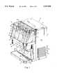
- FIG. 1is a perspective view of a beverage dispenser according to the present invention
- FIG. 2is an exploded perspective view of the dispenser of FIG. 1;
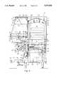
- FIG. 3is a side elevational view with portions removed and other portions in dashed line;
- FIG. 4is a partial schematic, partial cross-sectional view of the dispenser
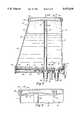
- FIGS. 5-8are cross-sectional views taken along section lines 5--5 of FIG. 1; 6--6 of FIG. 5; 7--7 of FIG. 3; and 8--8 of FIG. 7, respectively;
- FIG. 9is a cross-sectional view of an ice bath.
- FIG. 10is a partially broken away perspective view of an ice bath container and coils.
- a post-mix beverage dispenser 10has a housing 12 onto which a transparent bowl 14 is mounted.
- the bowlholds liquid 16 in each of four separately sealed compartments 18.
- a straight, plastic spray tube 20extends vertically to direct a spray of the liquid against an underside surface of a lid 40, thus causing the liquid to cascade downward in the bowl.
- Liquid 16is cooled to a sufficiently low temperature, preferably less than about 8° C. (45° F.), so that the bowl sweats, thus forming drops 22 of condensation that run down the sides of the bowl.
- the liquidshould be sufficiently low in temperature to cool the body so that condensation forms under most normal temperature and humidity conditions in which the dispenser would be used.
- One type of liquidcan be used in each of the compartments, or up to four different types of liquid can be provided in respective compartments.
- the liquid in the compartmentsis not actually dispensed for drinking; rather, the drink is made by reconstituting a concentrated syrup and water that are provided from external sources via conduits 24.
- These conduitsinclude four syrup lines, a potable water line, an AC power line, and a drain conduit.
- the syrupmay be held in a bag-in-box container in a remote location, while the water may be from a municipal water supply.
- the syrup and water conduitsare fluidly coupled to four dispensing valves 34, each of which combines the water and syrup in adjustable, pre-settable proportions and provides a cold drink.
- a cup 26is positioned over a grille 28 that is on a drip tray 29.
- Some valveshave a push handle switch 30 against which the user can push the cup to activate the switch by physical contact. If a valve is used that does not have such a switch, one or more buttons 32 can be provided to cause the dispenser to dispense the drink. Buttons 32, which are mounted on a bezel portion 33, are coupled to circuitry that is incorporated in the valve.
- the buttonscan include a "stop-and-hold" switch, which dispenses the drink for as long as the button is held, or, additionally or alternatively, can include buttons that provide measured portions. These measured portions can be preset by adjusting controls in system circuitry (not shown) or by using a learning mode in which the circuitry causes a drink to be dispensed for as long as a user causes the dispenser to dispense during a test run. Such a learning mode and an ability to set proportions in circuitry are provided, for example, in a model OJ 2000, a different type of post-mix dispenser that is available from Jet Spray Corp. (a type that has a refrigerated compartment for holding one or more containers of syrup within the housing, as in Reissue 33,943).
- bowl 14has an integral compartment-defining body 42, which has a gently sloping floor 45, side walls 37, three dividers 43 that define four compartments, and an open top.
- the bodyhas openings with integral downward extensions 46, 48 that define a front inlet and a rear outlet, respectively, for each compartment 18.
- Each front inletis fluidly coupled to a respective spray tube 20.
- the rear outletsare at a lowest part of the floor in each compartment for providing drainage to a respective pump 70.
- Condensate tray 44rests on a condensate tray 44 that is rigidly connected to a shelf 55 (FIG. 5).
- Condensate tray 44has a sloping floor 56 on which standoffs 54 are distributed so that when the body is on the tray, a space 57 is defined between them.
- a drain 58At the lowest point of the floor is a drain 58.
- the bowlsweats and the condensation rolls down the side of the body. Because of the space provided by spacers 54, the condensation collects on the floor of the tray and eventually is drained through drain 58 that is fluidly coupled to a drain conduit 59.
- the underside of the condensate trayhas integral extensions 47, 49 for fluidly coupling conduits 66, 68 to respective extensions 46, 48.
- Extensions 46, 47 and 48, 49are sealed with O-rings 51 that are disposed in annular grooves in extensions 46, 48.
- a two-piece lid 40 that covers the open top of the bodyhas a top piece 60 bonded to a bottom piece 62.
- the top piecehas a generally flat top with a downwardly directed flange 65 that extends around the periphery of the flat top.
- the bottom pieceis formed to define a sealed air space 64 over each compartment 18, while the top and bottom pieces meet and are bonded together at portions over dividers 43.
- the insulating air spaceprevents condensation from forming on the top of top piece 60.
- the spray tubeextends within about 1/8 inch of a bottom concave portion 61 of bottom piece 62.
- the lidrests on the body, preferably without any additional coupling means and without a gasket or other seal member.
- the lid, body, and spray tubesare all designed to fit together and to sufficiently seal while also being easy to disassemble and remove for maintenance and cleaning. Because of the mating extensions and the O-ring seals, the body can be easily separated from the tray by simply lifting it from the tray. Thus, the body can be easily removed and replaced for maintenance, replacement, or cleaning without removing, disturbing, or disconnecting the pumps, the valves, and conduits 66, 68 that are coupled to the tray.
- each liquid 16is fluidly coupled through a conduit 68 to a representative pump 70.
- the pumpcirculates the liquid from compartment 18 through conduit 68 and 72 and into a cooling system 76.
- the liquidhaving been cooled in the cooling system, is fluidly coupled to spray tube 20 via conduit 66.
- the cooling systemis remote from the bowl in that it is physically spaced from the bowl rather than extending into the bowl.
- the pumpis also fluidly coupled to a short conduit 80 through which the liquid in the compartment can be pumped out.
- a userremoves a cap 82 that covers an end of conduit 80.
- the short conduitdirect the liquid into a suitable container or into the drip tray.
- the liquid in the bowlWhile the liquid in the bowl is circulated to the cooling system, it is not fluidly coupled to dispenser valves 34, and thus the liquid is fluidly insulated or fluidly separated from the valves. This means that the liquid in the bowl and the drink that is dispensed are not the same and are not mixed.
- cooling system 76cools the liquids in the bowl, the potable water, and the syrup.
- System 76includes an ice bath assembly that has a box-shaped container 90. The container is filled to a desired level with cold bath water 77. To prevent overfilling, an overfill conduit 91 extends vertically through a floor of the container to the desired level.
- coil 92Disposed in the bath water is an evaporator coil 92 that winds around the inner periphery of the walls 93 of the container.
- coil 92carries a refrigerant, such as R134a, that is fluidly coupled to, and circulated by, a compressor 94 and a condenser 96.
- a fan 98(FIGS. 3 and 4) blows warm air through louvers 99 that can be located in either side walls 166 or in a rear wall 101 of the housing.
- the refrigerant in the evaporator coilcauses the coil to be substantially below 0° C., thus causing ice 78 to build up on, and completely surround, the coil.
- the icethus causes the bath water in the container to be kept very close to 0° C., typically about 0.1°-0.3° C.
- a drain conduit 103that is typically capped extends away from the floor of the container and is used when the container is emptied for cleaning or maintenance.
- a sensor 102(FIG. 9) is mounted in the container near coil 92 to sense a level of ice build-up by detecting water through capillary action. The sensor is electrically coupled to the compressor for causing the compressor to be activated and deactivated in response to the level of ice build-up.
- the compressorcan cause up to about fifteen pounds of ice to form on the evaporator coil. This ice creates a reserve cooling capacity that keeps the compressor from being run continuously.
- an agitator motor 97continuously drives an impeller 100 that creates turbulence in the water.
- the turbulencealso improves heat transfer between potable water in a water coil and the bath water.
- Copper heat sinks 104are mounted on the exterior surface of motor 98 and extend from the motor into the bath water.
- inverted U-shaped coils 110are welded to a floor of the ice bath container 90 and are fluidly coupled to a respective pump 70 and a respective compartment 18 through conduits 66, 72.
- Two of the coilsare positioned on either side of the impeller. The coils position and hold in place a water coil 95 that is pressed over coils 110 so that there is a close fit. This positioning is important because the water coil must be sufficiently spaced from the evaporator coil, which is coaxially disposed around the water coil, so that the potable water in the water coil does not freeze.
- the U-shaped coilsthus prevent the water coil from shifting after the water coil is positioned.
- two syrup coils 112are mounted against the exterior walls of each of two sides 114 of container 90. These coils are coupled to the exterior so that the design of the interior of the ice bath is not further complicated.
- the syrup coilsare connected against the sides with copper plates 116 that have channels 117 though which straight portions of the syrup coils extend.
- the heat sinking platesare held to the sides with threaded studs 118 that are welded to the sides.
- Around the exterior of the sides and the bottom of the containeris a one-inch thick layer of foam insulation 120 (FIG. 9).
- a cover 162On top of the container is a cover 162 that has 0.25 inches of foam insulation 164 on its underside. Ice bath container is supported on shelf 121 with standoffs 122.
- the syrup and potable water that are cooled by the ice bath assemblyare provided to dispenser valves 34 for dispensing.
- the syrupmay be provided from a bag-in-box container 124 that is kept at a remote location, e.g., behind a counter or in a storage room.
- Pump 125pumps syrup from container 124, to coils 112, conduit 128, and into valve 34.
- the potable water received by coil 95has a pressure that is regulated with a pressure regulator 170.
- the wateris then fluidly coupled to valve 34 through a conduit 126 to a splitting assembly (not shown) and then to each valve 34.
- valves 34in general and particularly to FIGS. 7 and 8, the water and syrup are provided to valves 34 through conduits 126, 128.
- the valveshave electrical lines 136 for connecting to electrical circuitry 138 (FIG. 4).
- Circuitry 138is coupled to buttons 32 (FIG. 1) for controlling dispensing.
- Adjustable control screws 130are on a front face of the valve. With these screws, a user can adjust the proportions of water and syrup.
- dials 132, 133for adjusting ball valves (not shown) that control the coupling between valves 34 and conduits 126, 128.
- Dials 132are set so that the handles point in the direction of flow, meaning that the ball valves are open; dials 133 have handles that are 90° from the handles of dials 132, indicating that the ball valves are closed.
- the ball valvesare closed as indicated by dials 133, a bail (not shown) is raised, and a front part 154 of the valve is removed from a rear part 156 at a break line 158.
- the front parthas the circuitry, which is most likely to require maintenance. Because of the need for access to dials 132, 133 to disconnect conduits 126, 128, typical dispensers provide a significant space above the valves for replacement and service.
- the valvesare rigidly mounted to a bracket 143 that has an L-shaped cross-section behind the valves. Behind the valves, the bracket has a portion that is in a plane parallel to rear wall 101 of the housing. At the sides of the dispenser, the bracket curves to two portions 147 that are in planes parallel to side walls 166 (FIG. 1) of the housing. Portion 147 are pivotally connected to vertical support members 144 through pivots 148. The support members have an L-shaped bend and are screwed to stationary vertical frame members 149. Plate 142 and bracket 143 are rotatable downward by 25° until they contact stops 146. These stops are projections of support members 144, and may, if desired, have end portions that slant downward by 25°.
- the bracketis normally held in a first operating position with release screws 150 that extend through support members 144 and engage threaded nuts attached to portions 147 of the bracket. When the screws are removed, the bracket 143 and plate 142 can be lowered. Thus, in a first operating position (in phantom line in FIG. 3), the valves partially extend through shelf 55 (FIG. 8) to a position very close to tray 44. In a second servicing position (in solid line in FIG. 3), the bracket pivots downward about 25° and rests on the stops to provide sufficient space to allow easy access to dials 132, 133 for maintenance and replacement (note that the pivoting angle is exaggerated in the figures).
- the housingincludes internal frame components, including shelf 121, shelf 55, and vertical frame members 149, that provides structural support and are constructed of 14 gauge galvanized steel. These frame components are assembled with 1/4 inch diameter rivets and bolts and are designed to eliminate shear forces on the rivets.
- the drip tray grille 28, side walls 166, bottom wall 168, rear wall 101, bezel portion 33, and a lower front wrapper 84 (FIG. 1) of the housingare preferably made of stainless steel.
- Body 42 and lid 40are preferably made from clear polycarbonate.
- the bodyis preferably completely clear and transparent, although it could be partially transparent.
- the bodyis preferably made from two molded pieces, one of which has side walls 37 and dividers 43, and a second of which has the floor with extensions 46, 48. These pieces are rigidly and tightly bonded together to be essentially an integral piece.
- the drip tray 29, lid 170, and condensate tray 44are molded from black polycarbonate.
- the evaporator coilis preferably a 0.375 (OD) copper conduit, while U-shaped coils 110, potable water coil 95, and syrup coils 112 are preferably stainless steel.
- the valveis preferably a model PRV1, available from Wilshire Corporation, Torrington, Conn. Other valves can also be used, including, for example, a valve made by Lancer for use with Coca-Cola® products.
- the pumpsare preferably G-100 A5 models, available from Beckett Corporation, Dallas, Tex.
- the ice bath containeris preferably made of stainless steel, and measures about 7.5 ⁇ 14.75 ⁇ 12 inches in dimension.
- coils similar to the U-shaped coilscould be used as syrup coils. While the coils have been shown as having a particular shape, such as having an S-shape, U-shape, or helical winding, these coils can take on any shape that accomplishes the desired function.
- the coils and the conduitscan refer to a single member or multiple members coupled together, such as coils 110 and conduits 66 and 72, or also multiple members with intervening components, such as pumps, valves, and regulators.
Landscapes
- Physics & Mathematics (AREA)
- Thermal Sciences (AREA)
- Engineering & Computer Science (AREA)
- Food Science & Technology (AREA)
- Devices For Dispensing Beverages (AREA)
Abstract
Description
Claims (19)
Priority Applications (8)
| Application Number | Priority Date | Filing Date | Title |
|---|---|---|---|
| US08/333,220US5537838A (en) | 1994-11-02 | 1994-11-02 | Beverage dispenser |
| KR1019950001166AKR960016817A (en) | 1994-11-02 | 1995-01-24 | Beverage dispensing device |
| CA002141501ACA2141501C (en) | 1994-11-02 | 1995-01-31 | Beverage dispenser |
| EP95410008AEP0711726B1 (en) | 1994-11-02 | 1995-02-03 | Beverage dispenser |
| DE69516974TDE69516974D1 (en) | 1994-11-02 | 1995-02-03 | Vending machine |
| JP7025547AJPH08133394A (en) | 1994-11-02 | 1995-02-14 | Soft drink dispenser |
| TW084102706ATW319753B (en) | 1994-11-02 | 1995-03-21 | |
| CN95105427ACN1131518A (en) | 1994-11-02 | 1995-04-29 | Beverage dispenser |
Applications Claiming Priority (1)
| Application Number | Priority Date | Filing Date | Title |
|---|---|---|---|
| US08/333,220US5537838A (en) | 1994-11-02 | 1994-11-02 | Beverage dispenser |
Publications (1)
| Publication Number | Publication Date |
|---|---|
| US5537838Atrue US5537838A (en) | 1996-07-23 |
Family
ID=23301857
Family Applications (1)
| Application Number | Title | Priority Date | Filing Date |
|---|---|---|---|
| US08/333,220Expired - LifetimeUS5537838A (en) | 1994-11-02 | 1994-11-02 | Beverage dispenser |
Country Status (8)
| Country | Link |
|---|---|
| US (1) | US5537838A (en) |
| EP (1) | EP0711726B1 (en) |
| JP (1) | JPH08133394A (en) |
| KR (1) | KR960016817A (en) |
| CN (1) | CN1131518A (en) |
| CA (1) | CA2141501C (en) |
| DE (1) | DE69516974D1 (en) |
| TW (1) | TW319753B (en) |
Cited By (19)
| Publication number | Priority date | Publication date | Assignee | Title |
|---|---|---|---|---|
| US5890626A (en)* | 1996-08-12 | 1999-04-06 | Imi Wilshire Inc. | Remote juice dispenser |
| US5984144A (en)* | 1997-03-18 | 1999-11-16 | Whitlenge Drink Equipment Ltd | Beverage dispensing apparatus |
| US6059145A (en)* | 1989-09-01 | 2000-05-09 | Juicy Whip, Inc. | Beverage dispenser |
| US6067895A (en)* | 1999-01-19 | 2000-05-30 | Buist; Ronald William | Brewer apparatus having a water flow control device |
| US6708741B1 (en) | 2000-08-24 | 2004-03-23 | Ocean Spray Cranberries, Inc. | Beverage dispenser |
| US6712237B2 (en) | 2001-05-15 | 2004-03-30 | The Coca-Cola Company | Simulated frozen beverage composition and method of manufacture thereof |
| US20050268624A1 (en)* | 2004-06-04 | 2005-12-08 | Voglewede Ronald L | Measured fill water dispenser for refrigerator freezer |
| US20060112719A1 (en)* | 2004-11-30 | 2006-06-01 | Grindmaster Corporation | Chilled beverage dispenser with cradle evaporator |
| US20060162360A1 (en)* | 2005-01-21 | 2006-07-27 | Mckibbin Terry T | Temperature-regulated storage and/or display module |
| US7293675B1 (en) | 2004-06-01 | 2007-11-13 | Veryfresh Juice Company, Inc. | Beverage line cleaning system |
| US20100078448A1 (en)* | 2008-09-29 | 2010-04-01 | Thomas Kolaco Kpabar | Portable multipurpose food and beverage insulated container and insulated water dispensing alternative |
| USD675677S1 (en)* | 2010-11-24 | 2013-02-05 | N&W Global Vending S.P.A. | Automatic beverage vending machines |
| USD689321S1 (en)* | 2012-01-12 | 2013-09-10 | Bunn-O-Matic Corporation | Espresso machine |
| US20160114297A1 (en)* | 2014-10-22 | 2016-04-28 | Oscar Perez | Chilled beverage dispensing machine |
| US9771252B2 (en)* | 2013-10-15 | 2017-09-26 | Streamline Beverage Pty Ltd | Beverage dispenser |
| WO2017180219A1 (en)* | 2016-04-12 | 2017-10-19 | Cornelius, Inc. | Rapid cooling systems for beverages |
| US20180216875A1 (en)* | 2014-08-22 | 2018-08-02 | Roasting Plant, Inc. | Beverage chiller and associated systems and methods |
| US20180354771A1 (en)* | 2015-11-03 | 2018-12-13 | Welbilt (Halesowen) Limited | Post-Mix Drink Dispensing System with Independently Controlled Syrup Pumps |
| US10472222B2 (en)* | 2016-10-11 | 2019-11-12 | Diqing Qiu | Double cooled draft beer machine |
Families Citing this family (8)
| Publication number | Priority date | Publication date | Assignee | Title |
|---|---|---|---|---|
| AU706886B2 (en)* | 1995-06-27 | 1999-07-01 | Coca-Cola Company, The | Fluid merchandiser for beverage dispenser |
| US5836481A (en)* | 1996-04-29 | 1998-11-17 | Lancer Partnership, Ltd. | Dispenser housing |
| AUPP502698A0 (en)* | 1998-08-04 | 1998-08-27 | Andale Repetition Engineering Pty. Limited | Beverage chiller |
| BR0215410B1 (en)* | 2002-11-15 | 2012-06-26 | device for dispensing liquids in beverage vending machines. | |
| GB2406328B (en)* | 2003-08-22 | 2006-10-11 | Imi Cornelius | Improvements in or relating to beverage dispense |
| GB2408091B (en)* | 2003-11-14 | 2008-08-20 | Imi Cornelius | Improvements In or Relating to Beverage Dispense |
| GB0800650D0 (en)* | 2008-01-15 | 2008-02-20 | Waterlogic Internat Uk Ltd | Water dispensers |
| US9764936B2 (en) | 2014-05-05 | 2017-09-19 | Grindmaster Corporation | Chilled beverage dispenser |
Citations (48)
| Publication number | Priority date | Publication date | Assignee | Title |
|---|---|---|---|---|
| US441628A (en)* | 1890-11-25 | Apparatus for supplying hot and cold drinks | ||
| US1649688A (en)* | 1924-03-01 | 1927-11-15 | Hulen M Harrison | Advertising machine |
| US1654379A (en)* | 1927-06-30 | 1927-12-27 | Matzka Wincenty | Displaying and dispensing apparatus for beverages |
| US1708212A (en)* | 1927-12-22 | 1929-04-09 | Richardson Corp | Beverage dispenser |
| US1760887A (en)* | 1927-10-24 | 1930-06-03 | Hartvig P Saugman | Beverage display |
| US1782943A (en)* | 1929-09-09 | 1930-11-25 | George H Hyland | Liquid-display apparatus |
| US1782944A (en)* | 1929-09-10 | 1930-11-25 | George H Hyland | Liquid-display fountain |
| US1799852A (en)* | 1928-09-01 | 1931-04-07 | William H Jones | Fountain display and advertising device |
| US1807966A (en)* | 1929-12-16 | 1931-06-02 | Visible Oil Merchandising Co I | Visible liquid display device |
| US2072841A (en)* | 1934-03-16 | 1937-03-02 | Continental Oil Co | Display device |
| US2186564A (en)* | 1939-05-09 | 1940-01-09 | Miller David | Activated display device |
| US2741400A (en)* | 1953-04-09 | 1956-04-10 | George W Hazzard | Juice display fountain |
| US3240395A (en)* | 1963-01-22 | 1966-03-15 | Fred M Carver | Self-contained portable dispensing system |
| US3255609A (en)* | 1964-05-25 | 1966-06-14 | Jet Spray Cooler Inc | Beverage dispenser |
| US3323813A (en)* | 1964-07-16 | 1967-06-06 | Jet Spray Cooler Inc | Manifold assembly |
| US3339334A (en)* | 1964-03-05 | 1967-09-05 | Rowan Henry John | Bar sections |
| US3341077A (en)* | 1965-11-01 | 1967-09-12 | Jet Spray Cooler Inc | Multi-beverage dispenser |
| US3342384A (en)* | 1965-04-30 | 1967-09-19 | Jet Spray Cooler Inc | Dispensing valve |
| US3360956A (en)* | 1966-12-08 | 1968-01-02 | Jet Spray Cooler Inc | Circulation system for beverage dispensers |
| US3385413A (en)* | 1966-06-03 | 1968-05-28 | Jet Spray Cooler Inc | Portion control and vending mechanism for dispensers |
| US3503541A (en)* | 1968-07-17 | 1970-03-31 | Jet Spray Cooler Inc | Multibeverage dispenser |
| US3539081A (en)* | 1968-07-05 | 1970-11-10 | Jet Spray Cooler Inc | Valve for beverage dispensers |
| US3568887A (en)* | 1967-11-13 | 1971-03-09 | Jet Spray Cooler Inc | Hot beverage dispenser |
| US3575536A (en)* | 1969-02-07 | 1971-04-20 | Jet Spray Cooler Inc | Pump for beverage dispenser |
| US3582096A (en)* | 1969-03-17 | 1971-06-01 | Jet Spray Cooler Inc | Gasket assembly for beverage dispenser |
| US3591055A (en)* | 1968-12-20 | 1971-07-06 | Jet Spray Cooler Inc | Mixing valve assembly for beverage dispensers |
| US3710981A (en)* | 1970-08-31 | 1973-01-16 | Jet Spray Cooler Inc | Three port valve assembly having selectively actuated valves |
| US3730144A (en)* | 1972-02-17 | 1973-05-01 | Jet Spray Cooler Inc | Hot water tank |
| US3730488A (en)* | 1972-05-18 | 1973-05-01 | Jet Spray Cooler Inc | Magnetic drive coupling for beverage dispenser |
| US3737076A (en)* | 1971-09-13 | 1973-06-05 | Jet Spray Cooler Inc | Atmospheric closed hot water tank system with separate expansion control |
| US3822565A (en)* | 1972-06-19 | 1974-07-09 | Jet Spray Cooler Inc | Beverage dispenser |
| US3851127A (en)* | 1971-09-03 | 1974-11-26 | Jet Spray Cooler Inc | Hot liquid dispenser reverse flow sensor with check valve slider and magnetically operated switch |
| US3880329A (en)* | 1970-05-13 | 1975-04-29 | Jet Spray Cooler Inc | Liquid dispensing, disposable container for use with a beverage dispenser |
| US3903628A (en)* | 1973-03-07 | 1975-09-09 | Anvar | Perpetual fountain |
| US3915341A (en)* | 1974-11-27 | 1975-10-28 | Jet Spray Cooler Inc | Manual fill hot beverage dispenser |
| US3920163A (en)* | 1973-07-11 | 1975-11-18 | Jet Spray Cooler Inc | Beverage dispenser with in-bowl whipper |
| US3927802A (en)* | 1974-03-05 | 1975-12-23 | Jet Spray Cooler Inc | Manual fill hot beverage dispenser |
| USD282617S (en) | 1983-08-01 | 1986-02-18 | Cole-Palmer Instrument Company | Combined dressing and condiment dispenser |
| US4610145A (en)* | 1984-09-21 | 1986-09-09 | Arzberger William A | Post mix fruit juice dispenser |
| US4645095A (en)* | 1984-03-19 | 1987-02-24 | Jet Spray Corp. | Syrup sensor for dispensing machine |
| US4717045A (en)* | 1984-03-19 | 1988-01-05 | Jet Spray Corp. | Syrup sensor for dispensing machine |
| US4728005A (en)* | 1984-03-19 | 1988-03-01 | Jet Spray Corp. | Self-fill system |
| US4757625A (en)* | 1986-11-07 | 1988-07-19 | Watkins Dana L | Display article with recharged phosphorescent medium |
| CA1244907A (en)* | 1984-03-19 | 1988-11-15 | Thomas A.O. Gross | Self-fill system |
| USRE33943E (en)* | 1984-09-21 | 1992-06-02 | Jet Spray Corp. | Post mix fruit juice dispenser |
| US5174239A (en)* | 1991-05-21 | 1992-12-29 | Sato Kogei Kabushiki Kaisha | Sealed-type aquarium device |
| USD337019S (en) | 1990-08-13 | 1993-07-06 | Grindmaster Corporation | Beverage dispenser |
| US5402914A (en)* | 1990-07-31 | 1995-04-04 | Zapp; Achim | Beverage dispensing device |
Family Cites Families (4)
| Publication number | Priority date | Publication date | Assignee | Title |
|---|---|---|---|---|
| US1689561A (en)* | 1927-04-15 | 1928-10-30 | Russell M Roddick | Dispensing apparatus |
| US1762126A (en)* | 1927-08-25 | 1930-06-03 | Autodrink Corp | Beverage-dispensing device |
| FR1260194A (en)* | 1960-03-25 | 1961-05-05 | Device for dispensing cold drinks | |
| AU5586786A (en)* | 1985-03-26 | 1986-10-23 | Paxman Bristow Coolers Ltd. | Apparatus for dispensing drinks |
- 1994
- 1994-11-02USUS08/333,220patent/US5537838A/ennot_activeExpired - Lifetime
- 1995
- 1995-01-24KRKR1019950001166Apatent/KR960016817A/ennot_activeWithdrawn
- 1995-01-31CACA002141501Apatent/CA2141501C/ennot_activeExpired - Fee Related
- 1995-02-03DEDE69516974Tpatent/DE69516974D1/ennot_activeExpired - Lifetime
- 1995-02-03EPEP95410008Apatent/EP0711726B1/ennot_activeExpired - Lifetime
- 1995-02-14JPJP7025547Apatent/JPH08133394A/ennot_activeWithdrawn
- 1995-03-21TWTW084102706Apatent/TW319753B/zhactive
- 1995-04-29CNCN95105427Apatent/CN1131518A/enactivePending
Patent Citations (48)
| Publication number | Priority date | Publication date | Assignee | Title |
|---|---|---|---|---|
| US441628A (en)* | 1890-11-25 | Apparatus for supplying hot and cold drinks | ||
| US1649688A (en)* | 1924-03-01 | 1927-11-15 | Hulen M Harrison | Advertising machine |
| US1654379A (en)* | 1927-06-30 | 1927-12-27 | Matzka Wincenty | Displaying and dispensing apparatus for beverages |
| US1760887A (en)* | 1927-10-24 | 1930-06-03 | Hartvig P Saugman | Beverage display |
| US1708212A (en)* | 1927-12-22 | 1929-04-09 | Richardson Corp | Beverage dispenser |
| US1799852A (en)* | 1928-09-01 | 1931-04-07 | William H Jones | Fountain display and advertising device |
| US1782943A (en)* | 1929-09-09 | 1930-11-25 | George H Hyland | Liquid-display apparatus |
| US1782944A (en)* | 1929-09-10 | 1930-11-25 | George H Hyland | Liquid-display fountain |
| US1807966A (en)* | 1929-12-16 | 1931-06-02 | Visible Oil Merchandising Co I | Visible liquid display device |
| US2072841A (en)* | 1934-03-16 | 1937-03-02 | Continental Oil Co | Display device |
| US2186564A (en)* | 1939-05-09 | 1940-01-09 | Miller David | Activated display device |
| US2741400A (en)* | 1953-04-09 | 1956-04-10 | George W Hazzard | Juice display fountain |
| US3240395A (en)* | 1963-01-22 | 1966-03-15 | Fred M Carver | Self-contained portable dispensing system |
| US3339334A (en)* | 1964-03-05 | 1967-09-05 | Rowan Henry John | Bar sections |
| US3255609A (en)* | 1964-05-25 | 1966-06-14 | Jet Spray Cooler Inc | Beverage dispenser |
| US3323813A (en)* | 1964-07-16 | 1967-06-06 | Jet Spray Cooler Inc | Manifold assembly |
| US3342384A (en)* | 1965-04-30 | 1967-09-19 | Jet Spray Cooler Inc | Dispensing valve |
| US3341077A (en)* | 1965-11-01 | 1967-09-12 | Jet Spray Cooler Inc | Multi-beverage dispenser |
| US3385413A (en)* | 1966-06-03 | 1968-05-28 | Jet Spray Cooler Inc | Portion control and vending mechanism for dispensers |
| US3360956A (en)* | 1966-12-08 | 1968-01-02 | Jet Spray Cooler Inc | Circulation system for beverage dispensers |
| US3568887A (en)* | 1967-11-13 | 1971-03-09 | Jet Spray Cooler Inc | Hot beverage dispenser |
| US3539081A (en)* | 1968-07-05 | 1970-11-10 | Jet Spray Cooler Inc | Valve for beverage dispensers |
| US3503541A (en)* | 1968-07-17 | 1970-03-31 | Jet Spray Cooler Inc | Multibeverage dispenser |
| US3591055A (en)* | 1968-12-20 | 1971-07-06 | Jet Spray Cooler Inc | Mixing valve assembly for beverage dispensers |
| US3575536A (en)* | 1969-02-07 | 1971-04-20 | Jet Spray Cooler Inc | Pump for beverage dispenser |
| US3582096A (en)* | 1969-03-17 | 1971-06-01 | Jet Spray Cooler Inc | Gasket assembly for beverage dispenser |
| US3880329A (en)* | 1970-05-13 | 1975-04-29 | Jet Spray Cooler Inc | Liquid dispensing, disposable container for use with a beverage dispenser |
| US3710981A (en)* | 1970-08-31 | 1973-01-16 | Jet Spray Cooler Inc | Three port valve assembly having selectively actuated valves |
| US3851127A (en)* | 1971-09-03 | 1974-11-26 | Jet Spray Cooler Inc | Hot liquid dispenser reverse flow sensor with check valve slider and magnetically operated switch |
| US3737076A (en)* | 1971-09-13 | 1973-06-05 | Jet Spray Cooler Inc | Atmospheric closed hot water tank system with separate expansion control |
| US3730144A (en)* | 1972-02-17 | 1973-05-01 | Jet Spray Cooler Inc | Hot water tank |
| US3730488A (en)* | 1972-05-18 | 1973-05-01 | Jet Spray Cooler Inc | Magnetic drive coupling for beverage dispenser |
| US3822565A (en)* | 1972-06-19 | 1974-07-09 | Jet Spray Cooler Inc | Beverage dispenser |
| US3903628A (en)* | 1973-03-07 | 1975-09-09 | Anvar | Perpetual fountain |
| US3920163A (en)* | 1973-07-11 | 1975-11-18 | Jet Spray Cooler Inc | Beverage dispenser with in-bowl whipper |
| US3927802A (en)* | 1974-03-05 | 1975-12-23 | Jet Spray Cooler Inc | Manual fill hot beverage dispenser |
| US3915341A (en)* | 1974-11-27 | 1975-10-28 | Jet Spray Cooler Inc | Manual fill hot beverage dispenser |
| USD282617S (en) | 1983-08-01 | 1986-02-18 | Cole-Palmer Instrument Company | Combined dressing and condiment dispenser |
| US4645095A (en)* | 1984-03-19 | 1987-02-24 | Jet Spray Corp. | Syrup sensor for dispensing machine |
| US4717045A (en)* | 1984-03-19 | 1988-01-05 | Jet Spray Corp. | Syrup sensor for dispensing machine |
| US4728005A (en)* | 1984-03-19 | 1988-03-01 | Jet Spray Corp. | Self-fill system |
| CA1244907A (en)* | 1984-03-19 | 1988-11-15 | Thomas A.O. Gross | Self-fill system |
| US4610145A (en)* | 1984-09-21 | 1986-09-09 | Arzberger William A | Post mix fruit juice dispenser |
| USRE33943E (en)* | 1984-09-21 | 1992-06-02 | Jet Spray Corp. | Post mix fruit juice dispenser |
| US4757625A (en)* | 1986-11-07 | 1988-07-19 | Watkins Dana L | Display article with recharged phosphorescent medium |
| US5402914A (en)* | 1990-07-31 | 1995-04-04 | Zapp; Achim | Beverage dispensing device |
| USD337019S (en) | 1990-08-13 | 1993-07-06 | Grindmaster Corporation | Beverage dispenser |
| US5174239A (en)* | 1991-05-21 | 1992-12-29 | Sato Kogei Kabushiki Kaisha | Sealed-type aquarium device |
Non-Patent Citations (2)
| Title |
|---|
| Tower Max Simulated Bubbler Owners Manual, no date available.* |
| Tower Max™ Simulated Bubbler Owners Manual, no date available. |
Cited By (27)
| Publication number | Priority date | Publication date | Assignee | Title |
|---|---|---|---|---|
| US6059145A (en)* | 1989-09-01 | 2000-05-09 | Juicy Whip, Inc. | Beverage dispenser |
| US5890626A (en)* | 1996-08-12 | 1999-04-06 | Imi Wilshire Inc. | Remote juice dispenser |
| US5984144A (en)* | 1997-03-18 | 1999-11-16 | Whitlenge Drink Equipment Ltd | Beverage dispensing apparatus |
| US6067895A (en)* | 1999-01-19 | 2000-05-30 | Buist; Ronald William | Brewer apparatus having a water flow control device |
| US6708741B1 (en) | 2000-08-24 | 2004-03-23 | Ocean Spray Cranberries, Inc. | Beverage dispenser |
| US6712237B2 (en) | 2001-05-15 | 2004-03-30 | The Coca-Cola Company | Simulated frozen beverage composition and method of manufacture thereof |
| US7293675B1 (en) | 2004-06-01 | 2007-11-13 | Veryfresh Juice Company, Inc. | Beverage line cleaning system |
| US20050268624A1 (en)* | 2004-06-04 | 2005-12-08 | Voglewede Ronald L | Measured fill water dispenser for refrigerator freezer |
| US7201005B2 (en)* | 2004-06-04 | 2007-04-10 | Whirlpool Corporation | Measured fill water dispenser for refrigerator freezer |
| AU2005202434B2 (en)* | 2004-06-04 | 2010-02-25 | Whirlpool Corporation | Measured fill water dispenser for refrigerator freezers |
| US7140196B2 (en) | 2004-11-30 | 2006-11-28 | Grindmaster Corporation | Chilled beverage dispenser with cradle evaporator |
| US20060112719A1 (en)* | 2004-11-30 | 2006-06-01 | Grindmaster Corporation | Chilled beverage dispenser with cradle evaporator |
| US20060162360A1 (en)* | 2005-01-21 | 2006-07-27 | Mckibbin Terry T | Temperature-regulated storage and/or display module |
| US7146821B2 (en)* | 2005-01-21 | 2006-12-12 | Mckibbin Terry Trent | Temperature-regulated storage and/or display module |
| US20100078448A1 (en)* | 2008-09-29 | 2010-04-01 | Thomas Kolaco Kpabar | Portable multipurpose food and beverage insulated container and insulated water dispensing alternative |
| US8313007B2 (en)* | 2008-09-29 | 2012-11-20 | Thomas Kolaco Kpabar | Portable multipurpose food and beverage insulated container and insulated water dispensing alternative |
| USD675677S1 (en)* | 2010-11-24 | 2013-02-05 | N&W Global Vending S.P.A. | Automatic beverage vending machines |
| USD689321S1 (en)* | 2012-01-12 | 2013-09-10 | Bunn-O-Matic Corporation | Espresso machine |
| US9771252B2 (en)* | 2013-10-15 | 2017-09-26 | Streamline Beverage Pty Ltd | Beverage dispenser |
| US20180216875A1 (en)* | 2014-08-22 | 2018-08-02 | Roasting Plant, Inc. | Beverage chiller and associated systems and methods |
| US11493269B2 (en)* | 2014-08-22 | 2022-11-08 | Roasting Plant, Inc. | Beverage chiller and associated systems and methods |
| US20160114297A1 (en)* | 2014-10-22 | 2016-04-28 | Oscar Perez | Chilled beverage dispensing machine |
| US20180354771A1 (en)* | 2015-11-03 | 2018-12-13 | Welbilt (Halesowen) Limited | Post-Mix Drink Dispensing System with Independently Controlled Syrup Pumps |
| US10626003B2 (en)* | 2015-11-03 | 2020-04-21 | Welbilt (Halesowen) Limited | Post-mix drink dispensing system with independently controlled syrup pumps |
| WO2017180219A1 (en)* | 2016-04-12 | 2017-10-19 | Cornelius, Inc. | Rapid cooling systems for beverages |
| US10317134B2 (en) | 2016-04-12 | 2019-06-11 | Cornelius, Inc. | Rapid cooling systems for beverages |
| US10472222B2 (en)* | 2016-10-11 | 2019-11-12 | Diqing Qiu | Double cooled draft beer machine |
Also Published As
| Publication number | Publication date |
|---|---|
| KR960016817A (en) | 1996-06-17 |
| JPH08133394A (en) | 1996-05-28 |
| CN1131518A (en) | 1996-09-25 |
| EP0711726A3 (en) | 1996-08-21 |
| CA2141501A1 (en) | 1996-05-03 |
| DE69516974D1 (en) | 2000-06-21 |
| CA2141501C (en) | 2004-12-21 |
| EP0711726A2 (en) | 1996-05-15 |
| EP0711726B1 (en) | 2000-05-17 |
| TW319753B (en) | 1997-11-11 |
Similar Documents
| Publication | Publication Date | Title |
|---|---|---|
| US5537838A (en) | Beverage dispenser | |
| US6698229B2 (en) | Low volume beverage dispenser | |
| US3892335A (en) | Beverage dispenser | |
| US4308975A (en) | Beverage cooling and dispensing apparatus | |
| US5353963A (en) | Post mix dispenser | |
| EP0176259B1 (en) | Post mix fruit juice dispenser | |
| US5564601A (en) | Beverage dispensing machine with improved liquid chiller | |
| US3331536A (en) | Drink dispenser | |
| JP3636472B2 (en) | Beverage dispensing device and mounting device | |
| US5890626A (en) | Remote juice dispenser | |
| KR102357243B1 (en) | Versatile and aesthetically refined keg dispenser | |
| US10743563B2 (en) | Frozen beverage dispenser | |
| US4921139A (en) | Refrigeration system for a beverage dispenser | |
| US6453955B1 (en) | Liquid dispensing system | |
| EP1241127B1 (en) | Beverage dispenser | |
| WO1996039350A2 (en) | Cylindrical drink dispenser | |
| US3206069A (en) | Apparatus and method for carbonating and dispensing beverages | |
| US11326825B2 (en) | Stand-alone ice and beverage appliance | |
| CA1338247C (en) | Convertible beverage dispenser | |
| EP0080253B1 (en) | Post-mix beverage dispenser | |
| US3584472A (en) | Bottled-water cooler | |
| CN216494874U (en) | Multifunctional refrigerator | |
| GB2160502A (en) | Drink supply system for postmixed drinks | |
| CA1251425A (en) | Beverage dispenser and refrigeration system therefor | |
| US20020003148A1 (en) | Method and apparatus for remotely dispensing beverages |
Legal Events
| Date | Code | Title | Description |
|---|---|---|---|
| AS | Assignment | Owner name:JET SPRAY CORP., MASSACHUSETTS Free format text:ASSIGNMENT OF ASSIGNORS INTEREST;ASSIGNORS:MILLS, JEFFREY P.;SARDYNSKI, GARY F.;REEL/FRAME:007219/0363 Effective date:19941101 | |
| FEPP | Fee payment procedure | Free format text:PAYOR NUMBER ASSIGNED (ORIGINAL EVENT CODE: ASPN); ENTITY STATUS OF PATENT OWNER: LARGE ENTITY | |
| STCF | Information on status: patent grant | Free format text:PATENTED CASE | |
| AS | Assignment | Owner name:IMI CORNELIUS INC., MINNESOTA Free format text:SECURITY AGREEMENT;ASSIGNOR:JET SPRAY CORP.;REEL/FRAME:009463/0908 Effective date:19980909 | |
| FEPP | Fee payment procedure | Free format text:PAT HLDR NO LONGER CLAIMS SMALL ENT STAT AS SMALL BUSINESS (ORIGINAL EVENT CODE: LSM2); ENTITY STATUS OF PATENT OWNER: LARGE ENTITY | |
| AS | Assignment | Owner name:IMI CORNELIUS INC., MINNESOTA Free format text:ASSIGNMENT OF ASSIGNORS INTEREST;ASSIGNOR:JET SPRAY CORP.;REEL/FRAME:009570/0371 Effective date:19981104 | |
| FPAY | Fee payment | Year of fee payment:4 | |
| FPAY | Fee payment | Year of fee payment:8 | |
| FPAY | Fee payment | Year of fee payment:12 | |
| REMI | Maintenance fee reminder mailed | ||
| AS | Assignment | Owner name:CORNELIUS, INC., MINNESOTA Free format text:CHANGE OF NAME;ASSIGNOR:IMI CORNELIUS, INC.;REEL/FRAME:033419/0460 Effective date:20140128 | |
| FEPP | Fee payment procedure | Free format text:PAYOR NUMBER ASSIGNED (ORIGINAL EVENT CODE: ASPN); ENTITY STATUS OF PATENT OWNER: LARGE ENTITY Free format text:PAYER NUMBER DE-ASSIGNED (ORIGINAL EVENT CODE: RMPN); ENTITY STATUS OF PATENT OWNER: LARGE ENTITY |