US5537688A - Hand covering with vibration-reducing bladder - Google Patents
Hand covering with vibration-reducing bladderDownload PDFInfo
- Publication number
- US5537688A US5537688AUS08/367,468US36746894AUS5537688AUS 5537688 AUS5537688 AUS 5537688AUS 36746894 AUS36746894 AUS 36746894AUS 5537688 AUS5537688 AUS 5537688A
- Authority
- US
- United States
- Prior art keywords
- bladder
- hand
- palm
- inflation
- user
- Prior art date
- Legal status (The legal status is an assumption and is not a legal conclusion. Google has not performed a legal analysis and makes no representation as to the accuracy of the status listed.)
- Expired - Lifetime
Links
- 239000012530fluidSubstances0.000claimsabstractdescription18
- 210000003811fingerAnatomy0.000claimsdescription34
- 210000003813thumbAnatomy0.000claimsdescription34
- 239000000463materialSubstances0.000claimsdescription26
- 239000004033plasticSubstances0.000claimsdescription4
- 238000004891communicationMethods0.000claimsdescription3
- 239000011358absorbing materialSubstances0.000claimsdescription2
- 238000000926separation methodMethods0.000claims3
- 239000000314lubricantSubstances0.000claims1
- 238000002955isolationMethods0.000abstractdescription47
- 238000005452bendingMethods0.000abstractdescription5
- 238000004519manufacturing processMethods0.000abstractdescription5
- 210000004027cellAnatomy0.000description36
- 210000004712air sacAnatomy0.000description30
- 239000010410layerSubstances0.000description14
- 229920001971elastomerPolymers0.000description12
- 210000004247handAnatomy0.000description10
- 239000000806elastomerSubstances0.000description9
- 230000032823cell divisionEffects0.000description7
- SAPGTCDSBGMXCD-UHFFFAOYSA-N(2-chlorophenyl)-(4-fluorophenyl)-pyrimidin-5-ylmethanolChemical compoundC=1N=CN=CC=1C(C=1C(=CC=CC=1)Cl)(O)C1=CC=C(F)C=C1SAPGTCDSBGMXCD-UHFFFAOYSA-N0.000description5
- 230000006835compressionEffects0.000description5
- 238000007906compressionMethods0.000description5
- 238000010276constructionMethods0.000description4
- 238000009413insulationMethods0.000description3
- 230000001050lubricating effectEffects0.000description3
- 231100000862numbnessToxicity0.000description3
- 230000005540biological transmissionEffects0.000description2
- 239000006260foamSubstances0.000description2
- 238000000034methodMethods0.000description2
- 230000003252repetitive effectEffects0.000description2
- 241001654170Caladenia catenataSpecies0.000description1
- 229920000742CottonPolymers0.000description1
- 239000004809TeflonSubstances0.000description1
- 229920006362Teflon®Polymers0.000description1
- 239000000853adhesiveSubstances0.000description1
- 230000001070adhesive effectEffects0.000description1
- 230000009286beneficial effectEffects0.000description1
- 210000004204blood vesselAnatomy0.000description1
- 230000006378damageEffects0.000description1
- 201000010099diseaseDiseases0.000description1
- 208000037265diseases, disorders, signs and symptomsDiseases0.000description1
- 230000000694effectsEffects0.000description1
- 239000004744fabricSubstances0.000description1
- 239000010985leatherSubstances0.000description1
- 239000000203mixtureSubstances0.000description1
- 238000012986modificationMethods0.000description1
- 230000004048modificationEffects0.000description1
- 230000001681protective effectEffects0.000description1
- 239000002356single layerSubstances0.000description1
- 239000007787solidSubstances0.000description1
- 208000024891symptomDiseases0.000description1
Images


Classifications
- F—MECHANICAL ENGINEERING; LIGHTING; HEATING; WEAPONS; BLASTING
- F16—ENGINEERING ELEMENTS AND UNITS; GENERAL MEASURES FOR PRODUCING AND MAINTAINING EFFECTIVE FUNCTIONING OF MACHINES OR INSTALLATIONS; THERMAL INSULATION IN GENERAL
- F16F—SPRINGS; SHOCK-ABSORBERS; MEANS FOR DAMPING VIBRATION
- F16F9/00—Springs, vibration-dampers, shock-absorbers, or similarly-constructed movement-dampers using a fluid or the equivalent as damping medium
- F16F9/02—Springs, vibration-dampers, shock-absorbers, or similarly-constructed movement-dampers using a fluid or the equivalent as damping medium using gas only or vacuum
- F16F9/04—Springs, vibration-dampers, shock-absorbers, or similarly-constructed movement-dampers using a fluid or the equivalent as damping medium using gas only or vacuum in a chamber with a flexible wall
- F16F9/0472—Springs, vibration-dampers, shock-absorbers, or similarly-constructed movement-dampers using a fluid or the equivalent as damping medium using gas only or vacuum in a chamber with a flexible wall characterised by comprising a damping device
- A—HUMAN NECESSITIES
- A41—WEARING APPAREL
- A41D—OUTERWEAR; PROTECTIVE GARMENTS; ACCESSORIES
- A41D19/00—Gloves
- A41D19/015—Protective gloves
- A41D19/01523—Protective gloves absorbing shocks or vibrations
- B—PERFORMING OPERATIONS; TRANSPORTING
- B25—HAND TOOLS; PORTABLE POWER-DRIVEN TOOLS; MANIPULATORS
- B25G—HANDLES FOR HAND IMPLEMENTS
- B25G1/00—Handle constructions
- B25G1/01—Shock-absorbing means
- F—MECHANICAL ENGINEERING; LIGHTING; HEATING; WEAPONS; BLASTING
- F16—ENGINEERING ELEMENTS AND UNITS; GENERAL MEASURES FOR PRODUCING AND MAINTAINING EFFECTIVE FUNCTIONING OF MACHINES OR INSTALLATIONS; THERMAL INSULATION IN GENERAL
- F16F—SPRINGS; SHOCK-ABSORBERS; MEANS FOR DAMPING VIBRATION
- F16F15/00—Suppression of vibrations in systems; Means or arrangements for avoiding or reducing out-of-balance forces, e.g. due to motion
- F16F15/02—Suppression of vibrations of non-rotating, e.g. reciprocating systems; Suppression of vibrations of rotating systems by use of members not moving with the rotating systems
- F16F15/023—Suppression of vibrations of non-rotating, e.g. reciprocating systems; Suppression of vibrations of rotating systems by use of members not moving with the rotating systems using fluid means
- F16F15/0232—Suppression of vibrations of non-rotating, e.g. reciprocating systems; Suppression of vibrations of rotating systems by use of members not moving with the rotating systems using fluid means with at least one gas spring
- A—HUMAN NECESSITIES
- A63—SPORTS; GAMES; AMUSEMENTS
- A63B—APPARATUS FOR PHYSICAL TRAINING, GYMNASTICS, SWIMMING, CLIMBING, OR FENCING; BALL GAMES; TRAINING EQUIPMENT
- A63B2225/00—Miscellaneous features of sport apparatus, devices or equipment
- A63B2225/62—Inflatable
- A—HUMAN NECESSITIES
- A63—SPORTS; GAMES; AMUSEMENTS
- A63B—APPARATUS FOR PHYSICAL TRAINING, GYMNASTICS, SWIMMING, CLIMBING, OR FENCING; BALL GAMES; TRAINING EQUIPMENT
- A63B71/00—Games or sports accessories not covered in groups A63B1/00 - A63B69/00
- A63B71/08—Body-protectors for players or sportsmen, i.e. body-protecting accessories affording protection of body parts against blows or collisions
- A63B71/081—Body-protectors for players or sportsmen, i.e. body-protecting accessories affording protection of body parts against blows or collisions fluid-filled, e.g. air-filled
Definitions
- hand-held vibrating or repeated impact-type toolsthat include, but are not limited to, chipping hammers, jackhammers, riveters, jackleg drills, rotary grinders and sanders, orbital sanders, chain saws, lawn mowers, and engine-powered string trimmers.
- Individualscan also be exposed to hand-induced vibration through clasping objects in their hands that are being ground, swagged, or repeatedly hammered.
- individualscan be exposed to hand-induced vibration while riding motor cycles, motor bikes, all-terrain vehicles, and other like vehicles.
- VWFvibration-induced white fingers
- Vibration levelscan be reduced by redesigning the tool or object or by placing a vibration isolation device between the hand and the tool or object that is being clasped by the hand.
- One of the methods for reducing the vibration energy directed into the handshas been the use of gloves that have an elastomer, foam or rubberlike material placed between the vibrating tool or object and the hand.
- Hand coveringssuch as gloves made with elastomers or rubberlike materials have proven to be ineffective in significantly reducing the vibration energy transmitted to hands from vibrating hand tools or objects clasped by the hand.
- To improve the vibration isolation characteristics of gloves with elastomers or rubberlike materialsit is necessary to make the elastomer or rubber pads used in the gloves very thick. This often makes the glove stiff and very difficult to use in clasping a hand tool or other object. Also, using gloves with thick elastomer or rubber pads causes the hands to become fatigued in a very short period of time.
- VWFThe occurrence of VWF is significantly affected by a cold environment. VWF is more prevalent in areas where workers must work either outside or inside in a cold environment. Gloves are often used in these environments to warm the hands, reducing the effects of cold on the prevalence of VWF in these environments. Using gloves with elastomer or rubberlike pads that are also designed to keep the hands warm creates the same problems that are associated with gloves that have extremely thick elastomer or rubberlike pads. The gloves tend to be stiff and often make it difficult to easily clasp a hand tool or other object.
- hand coveringsare desired which will more effectively reduce the vibration transmitted to the hand from the hand-held object, and will furthermore be thin, flexible, thermally insulative and relatively inexpensive.
- the problems associated with hand coverings that contain elastomer or rubberlike padsare solved with the air isolation hand coverings of the present invention.
- the air isolation hand coveringscontain a bladder to be filled with air or other compressible fluid.
- the bladderconsists of a plurality of interconnected or independent inflation cells, and is located in the hand coverings such that it will be placed between the hands and a tool or other object when the hands clasp the object.
- FIG. 1is a plot of the vibration transmissibility of three different air bladder configurations.
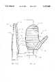
- FIG. 2-1is a plan view of a first embodiment of the air isolation hand covering of the present invention showing the bladder configuration.
- FIG. 2--2is a cross-sectional view of the first embodiment of the air isolation hand covering taken along line 2--2 in FIG. 2-1.
- FIG. 3-1is a plan view of a second embodiment of the air isolation hand covering of the present invention showing the bladder configuration.
- FIG. 3-2is a cross-sectional view of the second embodiment of the air isolation hand covering taken along line 3--3 in FIG. 3-1.
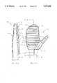
- FIG. 4-1is a plan view of a third embodiment of the air isolation hand covering of the present invention showing the bladder configuration.
- FIG. 4-2is a cross-sectional view of the third embodiment of the air isolation hand covering taken along line 4--4 in FIG. 4-1.
- FIG. 5-1is a plan view of a fourth embodiment of the air isolation hand covering of the present invention showing the bladder configuration.
- FIG. 5-2is a cross-sectional view of the fourth embodiment of the air isolation hand covering taken along line 5--5 in FIG. 5-1.
- FIG. 6-1is a plan view of a fifth embodiment of the air isolation hand covering of the present invention showing the bladder configuration.
- FIG. 6-2is a cross-sectional view of the third embodiment of the air isolation hand covering taken along line 6--6 in FIG. 6-1.
- FIG. 7is a cross-sectional view of a three-layer air bladder configuration with two adjacent rows of air cells.
- the present inventionis a hand covering which uses a bladder inflated with a compressible fluid to reduce vibration transmission through the hand covering, and further provide substantial thermal insulation benefits. While further discussion of the invention will refer to "air" as the compressible fluid being used, workers skilled in the art will recognize that any compressible fluid could be substituted for air within the spirit of the invention.
- FIG. 1shows tested vibration transmissibility values as a function of vibration frequency for three different air bladder configurations.
- Each of the air bladder configurationsconsist of a plurality of interconnected air cells, similar to those shown in FIGS. 2-6.
- the tested bladdershad cells diameters of 1/8 in. (3.2 mm), 1/4 in. (6.4 mm), and 3/8 in. (9.5 mm), respectively, and were inflated to pressures of about 15-25 psi.
- the larger the diameter of the plurality of interconnected air cavities in the bladderthe greater the air volume of the inflated bladder.
- the vibration transmissibility in FIG. 1is the ratio of the vibration amplitude directed into the hand divided by the vibration amplitude incident on the surface of the air bladder.
- the first embodiment of an air isolation hand covering of the present inventionis shown in FIG. 2.
- Glove 10consists of a palm portion 20, finger stalls 21, 22, 23 and 24, a thumb stall 25, and a gauntlet 26.
- the air isolation glovehas an inner liner 12 that is cut and formed into a hand covering structure.
- the inner lineris of a soft, moisture-absorbing material, such as cotton or other like material, for comfort when placed against a user's palm.
- the outer covering layer 13is of a protective, wear-resistant material such as leather, cloth or other like material.
- Placed between the inner liner 12 and the outer covering layer 13 in the inside palm portion 20 and finger and thumb stalls 21, 22, 23, 24, and 25is an air bladder 11. If desired the material 14 of the air bladder 11 may extend to the back side 15 of the glove 10.
- Air bladder 11includes a plurality of air cavities or cells 112.
- Cells 112are defined by cell divisions 30, where the inner layer 32 and outer layer 34 of bladder 11 are joined.
- Air bladder 11may be made of any flexible, air-tight material.
- the air bladder 11is preferably made from two layers of thermal plastic.
- cell divisions 30may be formed by adhesive, by application of heat and/or pressure to join the material of bladder 11, or by other processes. It is preferred that cell divisions 30 be as narrow as possible, such that inner layer 32 generally defines a flat surface adjacent the hand and outer layer 34 generally defines a flat surface facing outward from the hand.
- the material of air bladder 11should generally be inelastic, such that little or no deformation of cells 112 occurs at inflation pressure.
- Cells 112are linear, and are generally arranged in a planar configuration to cover the surface of palm portion 20, finger stalls 21, 22, 23 and 24, and thumb stall 25. Cells 112 may not entirely cover these surfaces. For instance, only 50% of the palm portion 20 may be covered. Similarly, cells 112 may not cover one or more of these surfaces at all. For instance, it may not be necessary to cover finger stalls 21, 22, 23 and 24. However, substantial coverage is desired for all portions of the hand that will contact the vibrating object.
- cells 112For many applications, it is unnecessary to include any cells 112 on the back side 15 of the glove 10. However, cells 112 provide significant thermal insulation for the hand, and it may be desired to include cells 112 on the back side 15 of the glove 10 for applications in cold environments.
- the cross-sectional shapes of the air cells 112can be circular as shown in FIG. 2--2.
- the cross-sectional shape of the air cells 112may also be triangular, square, hexagonal, octagonal, etc.
- the air bladder cavities 112 in the palm portion 20 and the finger and thumb stalls 21, 22, 23, 24 and 25can have the same cavity cross-sectional shape (circular, triangular, square, hexagonal, octagonal, etc.) or can have a mixture of cavity cross-sectional shapes (circular, triangular, square, hexagonal, octagonal, etc.).
- the cross-sectional dimensions of the air bladder cavities in the palm portion 20 and the finger and thumb stalls 21, 22, 23, 24 and 25can all be the same or they can be different.
- the cross-sectional shapes and related dimensions of the air cavities in the palm portion 20 and the finger and thumb stalls 21, 22, 23, 24 and 25can be varied to permit the air isolation glove to be configured to accommodate different glove applications.
- the cells 112may be interconnected through air passages 111 or may be independent. If the cells 112 are independent, they do not communicate with each other and they each have a certain pressure. Independent air cells 112 will generally be inflated during manufacture of glove 10.
- air cavitiesare interconnected, they can be made to communicate with each other through small air passages 111 that are molded into the bladder. This fluid communication allows bladder 11 to be inflated and deflated from a single source after manufacture of glove 10.
- the air passages 111can be small orifices between layers 32, 34 that allow adjacent air cavities 112 to communicate. Air passages 111 can be small elastic tubes placed between adjacent air cavities 112 that allow them to communicate with each other. The connection of adjacent cells 112 by air passages 111 can allow the air pressure in the plurality of interconnected air cavities 112 to equalize as the glove 10 clasps a tool handle or other object. Alternatively, air passages 111 may be formed so as to close when glove 10 is flexed or curled about a tool handle or other object. These closing air passages 111 allow inflation and deflation of bladder 11 from a single source, but do not allow fluid communication between adjacent cells 112 during use.
- Adjacent cells 112can be parallel to each other or they can be oriented at differing angles relative to each other, as is show in FIG. 2-1 where the thumb stall 25 is connected to the palm portion 20.
- cells 112will resist bending or flexing, but cell divisions 30 will provide joints which allow bending between cells 112.
- the orientation of cells 112 and cell divisions 30can generally be chosen to allow more easy flexing of glove 10 for its intended use. In the configuration shown, cell divisions 30 allow ready downward curling of finger stalls 21, 22, 23 and 24. Cell divisions 30 also allow ready bending of thumb stall 25 diagonally inward, and allow ready opposable bending between the thumb stall 25 and palm portion 20.
- the air bladder 11can be filled through a small hollow tube 113 attached to the endmost air cavity of the palm section 20 or to any other air cavity.
- the air bladder 11can also be inflated with a small manual pump 28 (shown schematically) attached to the hollow tube 113.
- a check and air-release valve 29 (shown schematically) attached between the small manual pump 28 and the hollow tube 113can be used to adjust the interior air pressure in the air bladder 11.
- bladder 11may also be inflated and completely sealed during manufacture having a certain interior air pressure. If bladder 11 is completely sealed, it would not be necessary to provide any inflating valve or pump.
- FIG. 3A second embodiment of the air isolation hand covering is shown in FIG. 3.
- Mitten 40consists of a palm portion 20, a finger portion 42, a thumb stall 25, and a gauntlet 26.
- the finger portion 42 of the second embodiment of the present inventionand the finger stalls 21, 22, 23 and 24 of the first embodiment of the present invention, the construction of the second embodiment of the present invention is the same as the first.
- FIG. 4A third embodiment of the air isolation hand covering is shown in FIG. 4.
- Glove 50consists of a palm portion 20, finger stalls 51, 52, 53 and 54, a thumb stall 55, and a gauntlet 26.
- the construction of the third embodiment of the present inventionis the same as the first embodiment of the present invention with the exception the finger stalls 21, 22, 23 and 24 and the thumb stall 25 are shortened and left open so that the fingers and thumb can extend exposed through the ends of the finger stalls 51, 52, 53 and 54 and the thumb stall 55.
- FIG. 5A fourth embodiment of the air isolation hand covering is shown in FIG. 5,
- Mitten 60consists of a palm portion 20, a finger portion 61, a thumb stall 65, and a gauntlet 26.
- the construction of the forth embodiment of the present inventionis the same as the second embodiment of the present invention with the exception the finger portion 42 and the thumb stall 25 are shortened and left open so that the fingers and thumb can extend exposed through the ends of the finger portion 61 and the thumb stall 65.
- FIG. 6A fifth embodiment of the air isolation hand covering is shown in FIG. 6.
- Mitten 70consists of a palm portion 20, a finger portion 42, a thumb stall 25, and a gauntlet 26.
- the construction of the fifth embodiment of the present inventionis the same as the second embodiment of the present invention with the following exception.
- Lubricating strips 72can be attached to the palm portion 20 and the finger portion 42 of the mitten. Lubricating strips 72 may be thin solid strips of teflon or other like material.
- Lubricating strips 72allow mitten 70 to slide relative to a vibrating hand-held object, such that the only vibrating forces which are substantially transmitted to mitten 70 are those normal to the grasping surface. Vibratory shear forces are not substantially transmitted to mitten 70, thus increasing the effectiveness of mitten 70. This embodiment is particularly useful for applications where the hands are used primarily to push a vibrating object that has substantial vibration motion tangent to the palm and finger surfaces of the mitten.
- the air bladders 11 in the five embodiments of the present invention show in FIGS. 2-7are composed of a single layer of air cells 112.
- the air bladders 11 in the five embodiments of the present inventioncan include two adjacent layers of air cells 85.
- the air bladder 81 in FIG. 7can be made from three layers 82, 83 and 84 of thermal plastic or other similar material that are bonded together.
- the three layers 82, 83 and 84can be bonded together to form air cells 85 cross-sectional shapes that are circular, triangular, square, hexagonal, octagonal, etc. If interconnection of adjacent cells 85 is desired, small orifices in the middle layer 83 can be used to allow air cells 85 to communicate with each other.
- the air bladders described in these preferred embodiments of FIGS. 2-7serve as an air spring which is very effective in reducing vibration or impact energy transmitted to the hand.
- the vibration transmissibility curvesillustrate several characteristics of the use of an air isolation bladder to reduce the vibration energy transmitted to the hand. Firstly, the effectiveness of the air isolation bladder in reducing vibration energy directed into the hand generally increases as the thickness of the air in the bladder increases. The 3/8 in. diameter bladder was generally most effective, while the 1/8 in. diameter bladder was generally least effective. It is believed that this difference is due to a greater volume of air in the larger diameter bladder, allowing a larger attenuation of vibration energy during air compression and expansion.
- the effectiveness of the air isolation bladderis related to the frequency of the vibrations.
- the air isolation bladders testedwere very effective at reducing vibration energy at frequencies over 40 Hz (the effectiveness increased with increasing diameter of the air bladder cells). The air bladder was even more effective in reducing vibration energy at frequencies above 400 Hz. Conversely, the air isolation bladders tested were not generally effective at reducing vibration energy at a frequency of less than 20-30 Hz. It is believe that the beneficial effect to the air isolation bladder is related to the time delay which occurs for air compression forces to be transmitted through the air cells. That is, air within the cell will not compress uniformly during each vibration cycle. Rather, force is transmitted through the air cell in a compression or sound wave, which does not travel instantaneously and does not compress air uniformly within the cell.
- each of the tested bladdershad particular points of reduced relative effectiveness (i.e., vibration transmissibility peaks) at frequencies of around 20 and 300 Hz. It is believed that the bladders have harmonic frequencies and that resonances are achieved at around 20 and 300 Hz.
- vibration transmissibilityis dependant upon the particular configuration of the air isolation bladder tested, but that similar characteristics would be observed in all isolation bladders. For instance, a bladder using a different arrangement of cells, a different inflation pressure or a different compressible fluid might be very effective at frequencies over 100 Hz, have a resonance frequency around 50 Hz, and be generally ineffective at frequencies less than 2-3 Hz.
- the air isolation hand coveringhas the following properties and functions:
- the air isolation hand coveringhas vibration isolation properties that are determined by the shape and configuration of the air bladder, the pressure in the bladder, the volume of the bladder, the compressible fluid used, and the grip force and push force used when clasping a tool or other object. Each of these parameters can be modified as desired for maximum vibration isolation for the particular use contemplated.
- the air isolation hand coveringcan be designed with sufficient air volume and air pressure in the air bladder so that the bladder will always maintain an air layer between the hand and tool or other object, irrespective of the grip and push forces employed during the operation associated with using the tool or other similar device.
- the air bladder in the air isolation hand coveringcan be filled with air during fabrication of the bladder, or it can be inflated or deflated by means of a small air pump and integral check and air-release valve connected to one of the air cavities of the bladder.
- the air bladder in the air isolation hand coveringis inflated by means of a small air pump and integral check and air-release value connected to one of the air cavities of the bladder, the air pressure in the air bladder can be controlled to adapt to the different needs of the wearers of the air isolation hand covering.
- the air isolation hand coveringis a lightweight glove that is comfortable to wear and that easily conforms to the different shapes of tool handles and other objects that may by clasped with the gloves. This significantly reduces the hand fatigue that is often associated with gloves that contain elastomer or rubberlike vibration isolation pads.
- the thermal plastic or other flexible material used to construct the air bladder in the air isolation hand coveringcan also be used to completely enclose the fingers and palm of the hand, providing effective lightweight thermal insulation to keep the hand warm.
- the air isolation hand coveringcan significantly reduce the tingle and numbness in the fingers and the hand fatigue that is experienced, when clasping vibrating hand tools or other vibrating objects.
- the air isolation hand coveringcan significantly reduce the incidence of VWF in worker populations or significantly increase the time period before symptoms associated with VWF begin to appear in worker populations.
- the air isolation hand coveringcan significantly reduce the discomfort that is associated with working with vibrating hand tools or holding onto vibrating objects.
Landscapes
- Engineering & Computer Science (AREA)
- General Engineering & Computer Science (AREA)
- Mechanical Engineering (AREA)
- Textile Engineering (AREA)
- Physics & Mathematics (AREA)
- Acoustics & Sound (AREA)
- Aviation & Aerospace Engineering (AREA)
- Gloves (AREA)
Abstract
Description
Claims (15)
Priority Applications (7)
| Application Number | Priority Date | Filing Date | Title |
|---|---|---|---|
| US08/367,468US5537688A (en) | 1994-12-30 | 1994-12-30 | Hand covering with vibration-reducing bladder |
| US08/565,921US5771490A (en) | 1994-12-30 | 1995-12-01 | Hand and handle covering with vibration-reducing bladder |
| PCT/US1995/016923WO1996020617A1 (en) | 1994-12-30 | 1995-12-28 | Hand and handle covering with vibration-reducing bladder |
| CA002206514ACA2206514C (en) | 1994-12-30 | 1995-12-28 | Hand and handle covering with vibration-reducing bladder |
| EP95944247AEP0800348B1 (en) | 1994-12-30 | 1995-12-28 | Hand and handle covering with vibration-reducing bladder |
| DE69530115TDE69530115T2 (en) | 1994-12-30 | 1995-12-28 | HAND AND HANDLE PROTECTION WITH DAMPING BELLOW |
| US08/886,991US5987705A (en) | 1994-12-30 | 1997-07-02 | Handle covering with vibration-reducing bladder |
Applications Claiming Priority (1)
| Application Number | Priority Date | Filing Date | Title |
|---|---|---|---|
| US08/367,468US5537688A (en) | 1994-12-30 | 1994-12-30 | Hand covering with vibration-reducing bladder |
Related Child Applications (1)
| Application Number | Title | Priority Date | Filing Date |
|---|---|---|---|
| US08/565,921Continuation-In-PartUS5771490A (en) | 1994-12-30 | 1995-12-01 | Hand and handle covering with vibration-reducing bladder |
Publications (1)
| Publication Number | Publication Date |
|---|---|
| US5537688Atrue US5537688A (en) | 1996-07-23 |
Family
ID=23447305
Family Applications (1)
| Application Number | Title | Priority Date | Filing Date |
|---|---|---|---|
| US08/367,468Expired - LifetimeUS5537688A (en) | 1994-12-30 | 1994-12-30 | Hand covering with vibration-reducing bladder |
Country Status (1)
| Country | Link |
|---|---|
| US (1) | US5537688A (en) |
Cited By (36)
| Publication number | Priority date | Publication date | Assignee | Title |
|---|---|---|---|---|
| US5771490A (en)* | 1994-12-30 | 1998-06-30 | Ergoair Inc. | Hand and handle covering with vibration-reducing bladder |
| US5920915A (en)* | 1998-09-22 | 1999-07-13 | Brock Usa, Llc | Protective padding for sports gear |
| US6000059A (en)* | 1998-08-28 | 1999-12-14 | Alliedsignal Inc. | Mechanical counter pressure glove for spacesuit |
| EP0981972A1 (en) | 1998-08-11 | 2000-03-01 | Astron Elastomerprodukte Gesellschaft mbH | Device to protect objects or body parts from vibrations |
| US6032300A (en)* | 1998-09-22 | 2000-03-07 | Brock Usa, Llc | Protective padding for sports gear |
| US6065150A (en)* | 1996-06-15 | 2000-05-23 | Huang; Ing Chung | Protective air cushion gloves |
| US6128779A (en)* | 1997-11-14 | 2000-10-10 | Jas D. Easton, Inc. | Limb protector |
| US6237193B1 (en)* | 1999-03-02 | 2001-05-29 | Robinson Knife Company | Compressible handle |
| US6430751B1 (en)* | 2001-02-28 | 2002-08-13 | Honeywell International Inc. | Dorsal metacarpal bladder and restraint for a mechanical counter pressure glove |
| US6591456B2 (en) | 2001-07-09 | 2003-07-15 | Bic Corporation | Cushioning device |
| US20030139258A1 (en)* | 2002-01-22 | 2003-07-24 | Riggall Cynthia A. | Therapeutic glove apparatus |
| US20040134228A1 (en)* | 2001-08-28 | 2004-07-15 | Sills Arthur A. | Finger ring fit adjuster |
| US20040226074A1 (en)* | 2003-05-14 | 2004-11-18 | Atom Corporation | Vibration-proof glove and production method thereof |
| US20040253085A1 (en)* | 2000-03-29 | 2004-12-16 | Up-N-Atom, Inc. | Truck bed design for automotive and equipment delivery |
| US20050042394A1 (en)* | 2003-08-20 | 2005-02-24 | Sawyer Daniel C. | Multi-layered sports playing field with a water draining, padding layer |
| US20050055752A1 (en)* | 2003-09-12 | 2005-03-17 | Hipolito Carrillo | Pneumatic device for boxing gloves to reduce head trauma |
| US20050089678A1 (en)* | 2003-08-20 | 2005-04-28 | Mead Steven R. | Multi-layered floorig composite including an acoustic underlayment |
| US7041141B2 (en)* | 2000-05-22 | 2006-05-09 | Motion Control, Inc. | Safety clutch for a prosthetic grip |
| US20060168706A1 (en)* | 2005-02-03 | 2006-08-03 | Auger Michel J G | Vibration damping device for glove |
| US20070261208A1 (en)* | 2006-05-15 | 2007-11-15 | Ishai Alon B | Cushioned handle |
| USD567454S1 (en) | 2007-02-07 | 2008-04-22 | Jean-Camille Raymond | Glove |
| US20080120754A1 (en)* | 2006-11-28 | 2008-05-29 | Wind Of Trade, Llc | Hand protector with friction inducing elements |
| USD570554S1 (en) | 2007-07-17 | 2008-06-03 | Jean-Camille Raymond | Glove |
| US7662468B2 (en) | 2000-10-06 | 2010-02-16 | Brock Usa, Llc | Composite materials made from pretreated, adhesive coated beads |
| US20100043113A1 (en)* | 2008-08-19 | 2010-02-25 | Nike, Inc. | Hand Grip |
| US20100083420A1 (en)* | 2007-03-21 | 2010-04-08 | Sparco S.P.A. | Glove |
| US20110055995A1 (en)* | 2009-09-10 | 2011-03-10 | Dassler Alfred K | Cycling Glove Support Area |
| US20110061249A1 (en)* | 2009-09-13 | 2011-03-17 | Man For Ma | Cutting Implement with Interchangeable/Replaceable Blades |
| US20110086570A1 (en)* | 2009-10-08 | 2011-04-14 | Richard Brockley | Inflatable or spring loaded thumb and/or finger(s) |
| US20120076985A1 (en)* | 2009-09-10 | 2012-03-29 | Dassler Alfred K | Cycling Glove And Support Area Pads |
| US20120246788A1 (en)* | 2011-03-28 | 2012-10-04 | Harrell Jeremy L | Multipurpose Cooling and Trauma Attenuating Devices and Associated Methods |
| CN103584375A (en)* | 2012-08-16 | 2014-02-19 | 沙嫣 | Safety protective glove |
| US20140201884A1 (en)* | 2007-04-06 | 2014-07-24 | NuDown, Inc. | Systems and methods for inflating an article of outdoor gear or apparel using a dry gas |
| US9174111B2 (en) | 2012-07-06 | 2015-11-03 | Warrior Sports, Inc. | Protective athletic equipment |
| CN113586658A (en)* | 2021-07-31 | 2021-11-02 | 森钠普环保材料江苏有限公司 | Protective plastic plate and production method thereof |
| US11523644B2 (en) | 2016-04-13 | 2022-12-13 | NuDown, Inc. | Inflatable garment with lightweight air pump and method of use |
Citations (17)
| Publication number | Priority date | Publication date | Assignee | Title |
|---|---|---|---|---|
| FR333946A (en)* | 1903-07-11 | 1903-12-07 | Peter Brusey Cow | Motor vehicle jerk and vibration protection system |
| SU961646A2 (en)* | 1981-02-25 | 1982-09-30 | Кубанский государственный университет | Worker mitten |
| US4471538A (en)* | 1982-06-15 | 1984-09-18 | Pomeranz Mark L | Shock absorbing devices using rheopexic fluid |
| US4478408A (en)* | 1980-12-22 | 1984-10-23 | Brueckner Georg F | Hand and forearm protective device for the interception of thrusts in martial arts |
| US4509228A (en)* | 1983-03-04 | 1985-04-09 | Kurt Landsberger | Inflatable implement handle |
| US4545841A (en)* | 1982-09-15 | 1985-10-08 | Donald Jackrel | Method for fabricating a glove with an intermediate membrane layer |
| US4559646A (en)* | 1983-09-21 | 1985-12-24 | Zwicker Knitting Mills | Work glove |
| US4820090A (en)* | 1988-06-03 | 1989-04-11 | Chen Pi Chi | Multipurpose handle grip for holding electric tools |
| US4918754A (en)* | 1988-05-04 | 1990-04-24 | William C. Heller, Jr. | Flocked glove and plastic sleeve member bonded thereto |
| US4942791A (en)* | 1989-08-14 | 1990-07-24 | Cooper Industries, Inc. | Ergonomic handle for hand-held tools |
| SU1623590A1 (en)* | 1988-08-18 | 1991-01-30 | Всесоюзный Центральный Научно-Исследовательский Институт Охраны Труда Вцспс | Gauntlet for vibration protection |
| SU1651831A1 (en)* | 1989-03-20 | 1991-05-30 | Челябинский Политехнический Институт Им.Ленинского Комсомола | Vibration-protection mitten |
| US5157807A (en)* | 1990-04-06 | 1992-10-27 | Metabowerke Gmbh & Co. | Vibration-cushioned handle |
| US5193246A (en)* | 1991-07-23 | 1993-03-16 | Huang Ing Chung | Air cushion grip with a cubic supporting structure and shock-absorbing function |
| US5195212A (en)* | 1991-10-23 | 1993-03-23 | Colwell Lori A | Tool handle cover |
| US5274846A (en)* | 1990-06-12 | 1994-01-04 | Hpi Health Protection, Inc. | Cushion having multilayer closed cell structure |
| US5345609A (en)* | 1992-09-29 | 1994-09-13 | Fabry Glove And Mitten Company | Protective glove having closed and isolated fluid filled cells |
- 1994
- 1994-12-30USUS08/367,468patent/US5537688A/ennot_activeExpired - Lifetime
Patent Citations (17)
| Publication number | Priority date | Publication date | Assignee | Title |
|---|---|---|---|---|
| FR333946A (en)* | 1903-07-11 | 1903-12-07 | Peter Brusey Cow | Motor vehicle jerk and vibration protection system |
| US4478408A (en)* | 1980-12-22 | 1984-10-23 | Brueckner Georg F | Hand and forearm protective device for the interception of thrusts in martial arts |
| SU961646A2 (en)* | 1981-02-25 | 1982-09-30 | Кубанский государственный университет | Worker mitten |
| US4471538A (en)* | 1982-06-15 | 1984-09-18 | Pomeranz Mark L | Shock absorbing devices using rheopexic fluid |
| US4545841A (en)* | 1982-09-15 | 1985-10-08 | Donald Jackrel | Method for fabricating a glove with an intermediate membrane layer |
| US4509228A (en)* | 1983-03-04 | 1985-04-09 | Kurt Landsberger | Inflatable implement handle |
| US4559646A (en)* | 1983-09-21 | 1985-12-24 | Zwicker Knitting Mills | Work glove |
| US4918754A (en)* | 1988-05-04 | 1990-04-24 | William C. Heller, Jr. | Flocked glove and plastic sleeve member bonded thereto |
| US4820090A (en)* | 1988-06-03 | 1989-04-11 | Chen Pi Chi | Multipurpose handle grip for holding electric tools |
| SU1623590A1 (en)* | 1988-08-18 | 1991-01-30 | Всесоюзный Центральный Научно-Исследовательский Институт Охраны Труда Вцспс | Gauntlet for vibration protection |
| SU1651831A1 (en)* | 1989-03-20 | 1991-05-30 | Челябинский Политехнический Институт Им.Ленинского Комсомола | Vibration-protection mitten |
| US4942791A (en)* | 1989-08-14 | 1990-07-24 | Cooper Industries, Inc. | Ergonomic handle for hand-held tools |
| US5157807A (en)* | 1990-04-06 | 1992-10-27 | Metabowerke Gmbh & Co. | Vibration-cushioned handle |
| US5274846A (en)* | 1990-06-12 | 1994-01-04 | Hpi Health Protection, Inc. | Cushion having multilayer closed cell structure |
| US5193246A (en)* | 1991-07-23 | 1993-03-16 | Huang Ing Chung | Air cushion grip with a cubic supporting structure and shock-absorbing function |
| US5195212A (en)* | 1991-10-23 | 1993-03-23 | Colwell Lori A | Tool handle cover |
| US5345609A (en)* | 1992-09-29 | 1994-09-13 | Fabry Glove And Mitten Company | Protective glove having closed and isolated fluid filled cells |
Cited By (56)
| Publication number | Priority date | Publication date | Assignee | Title |
|---|---|---|---|---|
| US5771490A (en)* | 1994-12-30 | 1998-06-30 | Ergoair Inc. | Hand and handle covering with vibration-reducing bladder |
| US6425134B1 (en)* | 1996-06-15 | 2002-07-30 | Ing Chung Huang | Protective air cushion gloves |
| US6065150A (en)* | 1996-06-15 | 2000-05-23 | Huang; Ing Chung | Protective air cushion gloves |
| US6128779A (en)* | 1997-11-14 | 2000-10-10 | Jas D. Easton, Inc. | Limb protector |
| EP0981972A1 (en) | 1998-08-11 | 2000-03-01 | Astron Elastomerprodukte Gesellschaft mbH | Device to protect objects or body parts from vibrations |
| US6202217B1 (en) | 1998-08-11 | 2001-03-20 | Astron Elastomerprodukte Gesellschaft M.B.H. | Device for the protection of objects or body parts against vibrations, in particular a vibration-damping glove or antivibration glove |
| US6000059A (en)* | 1998-08-28 | 1999-12-14 | Alliedsignal Inc. | Mechanical counter pressure glove for spacesuit |
| US6032300A (en)* | 1998-09-22 | 2000-03-07 | Brock Usa, Llc | Protective padding for sports gear |
| US6098209A (en)* | 1998-09-22 | 2000-08-08 | Brock Usa, Llc | Protective padding for sports gear |
| US6055676A (en)* | 1998-09-22 | 2000-05-02 | Brock Usa, Llc | Protective padding for sports gear |
| US6301722B1 (en) | 1998-09-22 | 2001-10-16 | Brock Usa, Llc | Pads and padding for sports gear and accessories |
| US6357054B1 (en) | 1998-09-22 | 2002-03-19 | Brock Usa, Llc | Protective padding for sports gear |
| US5920915A (en)* | 1998-09-22 | 1999-07-13 | Brock Usa, Llc | Protective padding for sports gear |
| US6453477B1 (en) | 1998-09-22 | 2002-09-24 | Brock Usa, Llc | Protective padding for sports gear |
| US6237193B1 (en)* | 1999-03-02 | 2001-05-29 | Robinson Knife Company | Compressible handle |
| US20040253085A1 (en)* | 2000-03-29 | 2004-12-16 | Up-N-Atom, Inc. | Truck bed design for automotive and equipment delivery |
| US7041141B2 (en)* | 2000-05-22 | 2006-05-09 | Motion Control, Inc. | Safety clutch for a prosthetic grip |
| US7662468B2 (en) | 2000-10-06 | 2010-02-16 | Brock Usa, Llc | Composite materials made from pretreated, adhesive coated beads |
| US6430751B1 (en)* | 2001-02-28 | 2002-08-13 | Honeywell International Inc. | Dorsal metacarpal bladder and restraint for a mechanical counter pressure glove |
| US6591456B2 (en) | 2001-07-09 | 2003-07-15 | Bic Corporation | Cushioning device |
| US20040134228A1 (en)* | 2001-08-28 | 2004-07-15 | Sills Arthur A. | Finger ring fit adjuster |
| US7150164B2 (en)* | 2001-08-28 | 2006-12-19 | Sills Arthur A | Finger ring fit adjuster |
| US20030139258A1 (en)* | 2002-01-22 | 2003-07-24 | Riggall Cynthia A. | Therapeutic glove apparatus |
| US7025709B2 (en) | 2002-01-22 | 2006-04-11 | Riggall Cynthia A | Therapeutic glove apparatus |
| US20040226074A1 (en)* | 2003-05-14 | 2004-11-18 | Atom Corporation | Vibration-proof glove and production method thereof |
| US6928658B2 (en)* | 2003-05-14 | 2005-08-16 | Atom Corporation | Vibration-proof glove and production method thereof |
| US20050042394A1 (en)* | 2003-08-20 | 2005-02-24 | Sawyer Daniel C. | Multi-layered sports playing field with a water draining, padding layer |
| US20050089678A1 (en)* | 2003-08-20 | 2005-04-28 | Mead Steven R. | Multi-layered floorig composite including an acoustic underlayment |
| US7244477B2 (en) | 2003-08-20 | 2007-07-17 | Brock Usa, Llc | Multi-layered sports playing field with a water draining, padding layer |
| US7043763B2 (en)* | 2003-09-12 | 2006-05-16 | Hipolito Carrillo | Pneumatic device for boxing gloves to reduce head trauma |
| US20050055752A1 (en)* | 2003-09-12 | 2005-03-17 | Hipolito Carrillo | Pneumatic device for boxing gloves to reduce head trauma |
| US20060168706A1 (en)* | 2005-02-03 | 2006-08-03 | Auger Michel J G | Vibration damping device for glove |
| US7865969B2 (en) | 2005-02-03 | 2011-01-11 | Impacto Protective Products Inc. | Vibration damping device for glove |
| US20070261208A1 (en)* | 2006-05-15 | 2007-11-15 | Ishai Alon B | Cushioned handle |
| US20080120754A1 (en)* | 2006-11-28 | 2008-05-29 | Wind Of Trade, Llc | Hand protector with friction inducing elements |
| USD567454S1 (en) | 2007-02-07 | 2008-04-22 | Jean-Camille Raymond | Glove |
| USD587409S1 (en)* | 2007-02-07 | 2009-02-24 | Wind Of Trade, Llc | Glove |
| US20100083420A1 (en)* | 2007-03-21 | 2010-04-08 | Sparco S.P.A. | Glove |
| US20140201884A1 (en)* | 2007-04-06 | 2014-07-24 | NuDown, Inc. | Systems and methods for inflating an article of outdoor gear or apparel using a dry gas |
| US9532610B2 (en)* | 2007-04-06 | 2017-01-03 | NuDown, Inc. | Systems and methods for inflating an article of outdoor gear or apparel using a dry gas |
| USD570554S1 (en) | 2007-07-17 | 2008-06-03 | Jean-Camille Raymond | Glove |
| US20100043113A1 (en)* | 2008-08-19 | 2010-02-25 | Nike, Inc. | Hand Grip |
| US8065750B2 (en)* | 2009-09-10 | 2011-11-29 | Dassler Alfred K | Cycling glove support area |
| US20110055995A1 (en)* | 2009-09-10 | 2011-03-10 | Dassler Alfred K | Cycling Glove Support Area |
| US20120076985A1 (en)* | 2009-09-10 | 2012-03-29 | Dassler Alfred K | Cycling Glove And Support Area Pads |
| US10104924B2 (en)* | 2009-09-10 | 2018-10-23 | Alfred K. Dassler | Cycling glove and support area pads |
| US8701294B2 (en) | 2009-09-13 | 2014-04-22 | Acme United Corporation | Cutting implement with interchangeable/replaceable blades |
| US20110061249A1 (en)* | 2009-09-13 | 2011-03-17 | Man For Ma | Cutting Implement with Interchangeable/Replaceable Blades |
| US20110086570A1 (en)* | 2009-10-08 | 2011-04-14 | Richard Brockley | Inflatable or spring loaded thumb and/or finger(s) |
| US20120246788A1 (en)* | 2011-03-28 | 2012-10-04 | Harrell Jeremy L | Multipurpose Cooling and Trauma Attenuating Devices and Associated Methods |
| US9174111B2 (en) | 2012-07-06 | 2015-11-03 | Warrior Sports, Inc. | Protective athletic equipment |
| CN103584375A (en)* | 2012-08-16 | 2014-02-19 | 沙嫣 | Safety protective glove |
| CN103584375B (en)* | 2012-08-16 | 2015-05-13 | 沙嫣 | Safety protective glove |
| US11523644B2 (en) | 2016-04-13 | 2022-12-13 | NuDown, Inc. | Inflatable garment with lightweight air pump and method of use |
| CN113586658A (en)* | 2021-07-31 | 2021-11-02 | 森钠普环保材料江苏有限公司 | Protective plastic plate and production method thereof |
| CN113586658B (en)* | 2021-07-31 | 2022-03-22 | 森钠普环保材料江苏有限公司 | Protective plastic plate and production method thereof |
Similar Documents
| Publication | Publication Date | Title |
|---|---|---|
| US5537688A (en) | Hand covering with vibration-reducing bladder | |
| US5771490A (en) | Hand and handle covering with vibration-reducing bladder | |
| US6723401B1 (en) | Vibration damping member and method of making same | |
| US5348360A (en) | Replaceable cushioned contoured gripping device for the handle of a tool | |
| US7004655B2 (en) | Cushioning element | |
| US6101628A (en) | Thumb protection device | |
| JPH03170276A (en) | Handgrip assembly arranged between tool and hand | |
| TWI457510B (en) | Vibration dampening material and uses for same | |
| AU746213B2 (en) | Glove for preventing carpal tunnel syndrome | |
| US6237193B1 (en) | Compressible handle | |
| US6694523B2 (en) | Ergonomic compression glove for hand, wrist, thumb and forearm support | |
| CA2458747A1 (en) | Vibration dampening grip cover for the handle of an implement | |
| KR20140052995A (en) | Vibration dampening material | |
| JPH11511838A (en) | Vibration damping member and method of manufacturing the same | |
| US9661883B2 (en) | Hand-tool brace | |
| CA2307507A1 (en) | Shock absorption system for a striking tool | |
| KR20140053085A (en) | Vibration dampening material | |
| US20050221738A1 (en) | Orbital sander with vertical handle | |
| US4089070A (en) | Conforming grip glove | |
| KR101891123B1 (en) | Safety gloves for work with protection function of fingers and back of hand and impact absorption and anti-slip function | |
| US20030229970A1 (en) | Shock-absorbing protective cover for pneumatic tool handle | |
| EP3515222B1 (en) | Glove for vibration insulation | |
| CN223354172U (en) | An auxiliary tool suitable for assembling pipelines of two device components | |
| WO2020147729A1 (en) | Shock-absorbing glove having cushions of various thicknesses | |
| WO2001013748A1 (en) | Vibration damping member and method of making same |
Legal Events
| Date | Code | Title | Description |
|---|---|---|---|
| AS | Assignment | Owner name:ERGOAIR, INC., NEVADA Free format text:ASSIGNMENT OF ASSIGNORS INTEREST;ASSIGNORS:REYNOLDS, DOUGLAS D.;JETZER, THOMAS C.;REEL/FRAME:007303/0318;SIGNING DATES FROM 19941228 TO 19941229 | |
| STCF | Information on status: patent grant | Free format text:PATENTED CASE | |
| REMI | Maintenance fee reminder mailed | ||
| FP | Lapsed due to failure to pay maintenance fee | Effective date:20000723 | |
| FEPP | Fee payment procedure | Free format text:PETITION RELATED TO MAINTENANCE FEES FILED (ORIGINAL EVENT CODE: PMFP); ENTITY STATUS OF PATENT OWNER: SMALL ENTITY | |
| FEPP | Fee payment procedure | Free format text:PETITION RELATED TO MAINTENANCE FEES GRANTED (ORIGINAL EVENT CODE: PMFG); ENTITY STATUS OF PATENT OWNER: SMALL ENTITY | |
| FPAY | Fee payment | Year of fee payment:4 | |
| SULP | Surcharge for late payment | ||
| PRDP | Patent reinstated due to the acceptance of a late maintenance fee | Effective date:20020204 | |
| FPAY | Fee payment | Year of fee payment:8 | |
| FEPP | Fee payment procedure | Free format text:PAYER NUMBER DE-ASSIGNED (ORIGINAL EVENT CODE: RMPN); ENTITY STATUS OF PATENT OWNER: SMALL ENTITY Free format text:PAYOR NUMBER ASSIGNED (ORIGINAL EVENT CODE: ASPN); ENTITY STATUS OF PATENT OWNER: SMALL ENTITY | |
| FPAY | Fee payment | Year of fee payment:12 |