US5537436A - Simultaneous analog and digital communication applications - Google Patents
Simultaneous analog and digital communication applicationsDownload PDFInfo
- Publication number
- US5537436A US5537436AUS08/076,520US7652093AUS5537436AUS 5537436 AUS5537436 AUS 5537436AUS 7652093 AUS7652093 AUS 7652093AUS 5537436 AUS5537436 AUS 5537436A
- Authority
- US
- United States
- Prior art keywords
- modem
- signal
- analog
- digital
- port
- Prior art date
- Legal status (The legal status is an assumption and is not a legal conclusion. Google has not performed a legal analysis and makes no representation as to the accuracy of the status listed.)
- Expired - Fee Related
Links
- 238000004891communicationMethods0.000titleabstractdescription20
- 230000005540biological transmissionEffects0.000claimsdescription10
- 230000006870functionEffects0.000claimsdescription10
- 230000000007visual effectEffects0.000claims2
- 230000008878couplingEffects0.000claims1
- 238000010168coupling processMethods0.000claims1
- 238000005859coupling reactionMethods0.000claims1
- 238000000034methodMethods0.000abstractdescription15
- 239000013598vectorSubstances0.000abstractdescription13
- 230000008901benefitEffects0.000abstractdescription7
- 238000010586diagramMethods0.000description13
- 238000013459approachMethods0.000description9
- 239000003795chemical substances by applicationSubstances0.000description9
- 208000032041Hearing impairedDiseases0.000description8
- 230000008569processEffects0.000description5
- 238000005070samplingMethods0.000description5
- 230000001413cellular effectEffects0.000description4
- 230000000694effectsEffects0.000description4
- 230000002452interceptive effectEffects0.000description4
- 230000011664signalingEffects0.000description4
- 230000006978adaptationEffects0.000description3
- 230000003044adaptive effectEffects0.000description3
- 238000001914filtrationMethods0.000description3
- 230000004044responseEffects0.000description3
- 230000009471actionEffects0.000description2
- 230000009286beneficial effectEffects0.000description2
- 238000004364calculation methodMethods0.000description2
- 238000006243chemical reactionMethods0.000description2
- 239000002131composite materialSubstances0.000description2
- 230000003111delayed effectEffects0.000description2
- 238000013461designMethods0.000description2
- 238000001514detection methodMethods0.000description2
- 238000003745diagnosisMethods0.000description2
- 238000005516engineering processMethods0.000description2
- 230000006872improvementEffects0.000description2
- 238000012423maintenanceMethods0.000description2
- 238000013139quantizationMethods0.000description2
- 230000001131transforming effectEffects0.000description2
- 238000004458analytical methodMethods0.000description1
- 230000003416augmentationEffects0.000description1
- 230000006399behaviorEffects0.000description1
- 230000036772blood pressureEffects0.000description1
- 230000015556catabolic processEffects0.000description1
- 230000003750conditioning effectEffects0.000description1
- 239000000470constituentSubstances0.000description1
- 238000007796conventional methodMethods0.000description1
- 238000006731degradation reactionMethods0.000description1
- 230000001419dependent effectEffects0.000description1
- 230000002708enhancing effectEffects0.000description1
- 238000003912environmental pollutionMethods0.000description1
- 239000000835fiberSubstances0.000description1
- 230000036039immunityEffects0.000description1
- 230000001771impaired effectEffects0.000description1
- 230000003993interactionEffects0.000description1
- 238000012544monitoring processMethods0.000description1
- 230000002093peripheral effectEffects0.000description1
- 238000007781pre-processingMethods0.000description1
- 230000008439repair processEffects0.000description1
- 230000035945sensitivityEffects0.000description1
- 238000001228spectrumMethods0.000description1
- 230000001360synchronised effectEffects0.000description1
- 238000012360testing methodMethods0.000description1
- 238000012549trainingMethods0.000description1
Images


Classifications
- H—ELECTRICITY
- H04—ELECTRIC COMMUNICATION TECHNIQUE
- H04L—TRANSMISSION OF DIGITAL INFORMATION, e.g. TELEGRAPHIC COMMUNICATION
- H04L27/00—Modulated-carrier systems
- H04L27/32—Carrier systems characterised by combinations of two or more of the types covered by groups H04L27/02, H04L27/10, H04L27/18 or H04L27/26
- H04L27/34—Amplitude- and phase-modulated carrier systems, e.g. quadrature-amplitude modulated carrier systems
- H04L27/345—Modifications of the signal space to allow the transmission of additional information
- H04L27/3461—Modifications of the signal space to allow the transmission of additional information in order to transmit a subchannel
- H04L27/3483—Modifications of the signal space to allow the transmission of additional information in order to transmit a subchannel using a modulation of the constellation points
- H—ELECTRICITY
- H04—ELECTRIC COMMUNICATION TECHNIQUE
- H04J—MULTIPLEX COMMUNICATION
- H04J7/00—Multiplex systems in which the amplitudes or durations of the signals in individual channels are characteristic of those channels
- H—ELECTRICITY
- H04—ELECTRIC COMMUNICATION TECHNIQUE
- H04L—TRANSMISSION OF DIGITAL INFORMATION, e.g. TELEGRAPHIC COMMUNICATION
- H04L27/00—Modulated-carrier systems
- H04L27/18—Phase-modulated carrier systems, i.e. using phase-shift keying
Definitions
- This inventionrelates to simultaneous transmission of analog and digital signals and, more particularly, to applications that employ simultaneous transmission of analog signals and digital signals in a non-multiplexed manner and in a generally co-extensive frequency band.
- voice and datawhen voice and data is transmitted simultaneously over a channel, it is typically transmitted either via frequency-division multiplexing or time-division multiplexing.
- frequency-division multiplexingthe data channel and the voice channel are allocated different sub-bands of the channel's bandwidth. Examples of that are U.S. Pat. Nos. 4,757,495, 4,672,602, and 4,546,212.
- time-division multiplexing arrangementsvoice signals are sampled, digitized and interleaved with digital data to form a single information stream which is communicated over the available channel. Practically every digital carrier system (e.g. the T1 carrier system) is an example of that.
- U.S. Pat. No. 4,512,013, issued Apr. 16, 1985presents an interesting approach that is close to a frequency division multiplexing arrangement for simultaneous voice and data.
- the arrangementfilters the speech signal and adds thereto a modulated narrowband signal to form the transmitted signal.
- the narrowband modulated signalderives from a narrowband digital input signal that is modulated with a carrier, thereby shifting the narrow-band up in frequency to a position in the spectrum where there is little speech energy.
- the digital signalis recovered through appropriate demodulation. Thereafter, the recovered digital signal is remodulated to replicate the transmitter's operation, adaptively filtered to account for channel characteristics, and subtracted from the received signal.
- a modemfilters the digital signal (i.e., shifts it in frequency) to form a band-limited signal and modulates that signal to reside within the passband of the communication channel.
- that passbandmay be between 300 Hz and 3500 Hz.
- Quadrature modulationis often depicted as a two-dimensional signal space. Use of the signal space to send voice information is disclosed in U.S. Pat. No. 5,081,647 issued Jan. 14, 1992.
- Analog information and digital informationis communicated concurrently when employing the principles of this invention.
- the digital signalis divided into symbols, and the symbols are mapped onto the signal space with a preset distance between them.
- the analog signalgenerally limited in magnitude to less than half the distance separating the symbols, is converted to component signals and added (i.e., vector addition) to the symbols.
- the sum signalis then transmitted to the receiver where the symbols are detected and subtracted from the received signal to yield the analog signal components.
- the transmitted analog signalis recreated from those components.
- the digital stream entering the transmitter sectionis divided into words, and each word is mapped to a pair of symbol components.
- the analog signal entering the transmitter sectionis sampled and each pair of successive samples forms a set of analog vector components.
- the analog vector componentsare added, respectively, to the symbol components and the component sums are QAM modulated to form the output signal.
- the pairs of analog samplescan be derived by simply delaying the analog signal and sampling both the delayed and the undelayed versions.
- the signalis first demodulated and the digital signal is detected in accord with standard modulation technology.
- the detected digital signalis then subtracted from the received signal to form analog samples pairs that are combined to reconstitute the analog signal.
- Line equalization, echo-canceling, pre-emphasis, and other improvements that are known in the modem artcan be incorporated in various embodiments that employ the principles of this invention.
- FIG. 1presents the basic structure of a prior art modem
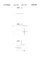
- FIG. 2shows the signal space and an illustrative signal constellation for the FIG. 1 system
- FIG. 3shows the signal space of a QAM analog system
- FIG. 4shows the signal space of an alternating digital and analog system
- FIG. 5shows the signal space of a combined digital and analog system
- FIG. 6presents one embodiment of a transmitter section for a combined digital and analog system
- FIG. 7depicts the vector addition that forms the signal space of FIG. 5;
- FIG. 8presents one orthogonal modulation approach
- FIG. 9illustrates the arrangements that permit more than one analog signal source to be transmitted simultaneously
- FIG. 10details the major elements in a receiver responsive to the FIG. 5 signal space
- FIG. 11presents a block diagram of a receiver that includes adaptive equalization
- FIG. 12presents the block diagram of an entire modem
- FIG. 13presents a slightly different embodiment of the FIG. 12 modem
- FIG. 14depicts one structure for scrambling analog samples
- FIG. 15presents a block diagram of a privacy scrambler employing pseudo-random multiplication of the analog samples
- FIG. 16illustrates a processor 75 being interposed between the analog input and the analog port of the modem, with the processor being adapted to carry out signal preprocessing functions, such as linear predictive coding,
- FIG. 17presents a block diagram illustrating linear predictive coding
- FIG. 18presents a block diagram illustrating the alternative use of different signal spaces
- FIG. 19depicts use of the disclosed modem in connection with software support
- FIG. 20depicts use of the disclosed modem in connection with apparatus diagnosis and maintenance
- FIG. 21depicts use of the disclosed modem in connection with apparatus diagnosis and maintenance with the modem coupled to a wireless base station
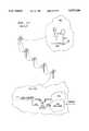
- FIG. 22shows use of the disclosed modem in connection with a call center
- FIG. 23shows use of the disclosed modem in an interactive game environment
- FIG. 24presents a block diagram depicting use of the disclosed modem in an interactive mode with a television display
- FIG. 25presents the disclosed modem in a PCMCIA configuration, adapted for inclusion with wireless apparatus, such as a wireless computer,
- FIG. 26shows use of the disclosed modem in a telephone instrument that includes video capabilities
- FIG. 27shows use of the disclosed modem in a fax machine
- FIG. 28shows use of the disclosed modem in a personal computer
- FIG. 29shows use of the disclosed modem in a "plain old" telephone
- FIG. 30presents a block diagram that includes the disclosed modem and means for bypassing the modem when it is inoperative
- FIG. 31illustrates an arrangement for text/speech uses of the modem disclosed herein
- FIG. 32describes an arrangement that may be employed in connection with the hearing-impaired
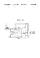
- FIG. 33presents a general block diagram for a multi-media answering machine.
- FIG. 1presents a very basic block diagram of a modem that communicates digital data via quadrature modulation techniques.
- Section 100is the modem's transmitter section and section 200 is the modem's receiver section.
- digital datais applied in FIG. 1 to a 1-to-2 mapper 110, and mapper 110 develops two outputs which typically are referred to as the in-phase and quadrature samples.
- the in-phase samplesare applied via low pass filter 150 to modulator 120, which multiplies the applied signal by a carrier--i.e., sin ⁇ t in FIG. 1.
- the quadrature samplesare applied via low pass filter 160 to modulator 130, which multiplies the applied signal by a second carrier.
- the second carrieris orthogonal to the first carrier; namely, cos ⁇ t.
- Filters 150 and 160must be bandlimited to no more than ⁇ , in order to avoid aliasing and to at least half the inverse of the output sample rate of mapper 110.
- the output signals of modulators 120 and 130are added in element 140 to develop the analog signal of the modem' s transmitter section.
- the digital data applied to the FIG. 1 apparatusis a stream of bits.
- Element 110views the incoming signal as a stream of symbols that each comprise a preselected number of consecutive bits, and maps each symbol into an in-phase analog sample and a quadrature analog sample.
- the in-phase and quadrature samples delivered by element 110in effect, specify a location in the signal space of FIG. 2. Accordingly, the set of possible samples that element 110 can produce corresponds to a set of sample points (i.e., a constellation of points) in the signal space depiction of FIG. 2.
- a 4-point signal constellationis shown, by way of illustration, in FIG. 2. It is well known, however, that one can create signal point constellations with a larger number of signal points.
- the signal spacecan be divided into regions and the receiver's decision is made with respect to the region in which the received signal is located. We call these regions "neighborhood" regions.
- the modulated signalis applied to demodulator 210.
- Demodulator 210recovers the in-phase and quadrature components and applies them to slicer 220.
- Slicer 220converts the in-phase and quadrature components into symbols and applies the symbols to demapper 230.
- De-mapper 230maps the symbols into bit streams to form the recovered digital data stream.
- the signal received by demodulator 210would be precisely the same as the signal sent by adder 140, and a determination of neighborhood regions in which the signal is found (by slicer 220) would be relatively simple and error-free.
- noise that is added to the transmitted signalshifts the received signal in the signal space and modifies the input to slicer 220.
- a noise signal that adds to the signal flowing through the communication channelcorresponds to a vector signal in the signal space of FIG. 2 that is added to a transmitted sample point. That added vector is of unknown magnitude and unknown phase. Consequently, added noise converts a transmitted signal that corresponds to a point in the signal space into a region in the signal space. This phenomenon is depicted in FIG. 2 by circle 11. Some refer to this circle as a signal space "noise cloud" surrounding the transmitted signal.
- FIG. 3A transmitter signal space in accordance with this revolutionary approach is depicted in FIG. 3 where a plurality of signal points are depicted randomly within the signal space. These points are illustrative of the various vectors that the transmitter is allowed to send out. There are no more "constellations of points", where a decision must be made between constellation points; there is only the entirety of the signal space.
- FIG. 3depicts analog signals that are mapped onto a signal space.
- the viable signal space of FIG. 3may be rectangular.
- the next innovationis to alternate between the signal spaces of FIG. 2 and FIG. 3. That is, the innovation is to send customer analog signals or customer digital signals as the need arises. This is depicted in FIG. 4.
- the analog signals that form "signal clouds" around each digital constellation pointshould be restricted in their dynamic range to be totally contained within the neighborhood regions.
- constellation sizewhich directly affects digital through-put
- dynamic range of the transmitted analog signalwhich in some situations translates to "resolution”
- FIG. 6depicts an arrangement that very basically illustrates the principles disclosed herein. It includes a 1-to-2 dimensional mapper 60 responsive to digital signals applied on line 61. Mapper 60 develops two output signals on lines 62 and 63, each of which possesses pulses with quantized amplitudes that relate to the digital signals arriving on line 61. FIG. 6 also includes a 1-to-2 mapper 50 that responds to an applied analog signal on line 51, and it develops two output signals on lines 52 and 53, each of which possesses pulses with continuous amplitudes that relate to the analog signal on line 51. Outputs 52 and 62 are combined in adder 70 and outputs 53 and 63 are combined in adder 80.
- the outputs of adders 70 and 80form the components of the signals that are represented by the signal space of FIG. 5. As in FIG. 1, the outputs of adders 70 and 80 are applied via low pass filters 150 and 160 to modulators 120 and 130 and summed in adder 140 to form a modulated signal as is typically known in the modem art.
- element 60is depicted as a 1-to-2 mapper.
- element 60can be an M-to-N mapper. That is, element 60 can be responsive to a plurality (M) of digital signals and it can develop a different plurality (N) of output signals.
- element 50can be a J-to-K encoder that is responsive to a plurality of analog signals.
- the collection of elements that follow elements 50 and 60i.e., elements 70, 80, 120, 130, 140, 150 and 160), which form orthogonal modulator 90 can be constructed to be responsive to whatever plurality of outputs of that elements 50 and 60 are designed to produce (e.g., three dimensional space, four dimensional space, etc.).
- those elementsmust account for all of the applied input signals, and that means that they must be able to handle K or N signals, whichever is larger. In such a circumstance, however, the user can assume that the larger of the two (K or N) is the dimensionality of the system, and some of the dimensions have either no digital data, or no analog data, whichever applies. Of course, if there are "dimensions" for which there is no digital or analog data, other information can be sent over those dimensions, such as equalization "side" information.
- the N pluralities of output signals of elements 50 and 60correspond to the collection of components of vectors in multi-dimensional space; e.g., N-dimensional space.
- the coordinates of this multi-dimensional spacecorrespond to the orthogonal modulation signals within orthogonal modulator 90.
- the two orthogonal modulation signalsare cos ⁇ t and sin ⁇ t, but other modulation signals are also possible; for example, code division multiplexing (CDMA) templates.
- orthogonal modulation signalsare modulation signals that develop a transmitted signal comprising concurrent element signals and yet allow the receiver to separate the received signal into its constituent element signals, those being the signals developed in response to each of the modulation signals. It may also be observed that, relative to FIG. 5, orthogonal modulator 90 performs vector summation of the symbol vector represented by the components developed by element 60 with the analog information vector represented by the components developed by element 50. This is depicted in FIG. 7.
- orthogonal modulator 90can simply be a bandshifting means. To the extent that the output of adder 70 (for example) is band-limited, the output of adder 80 can be shifted beyond the band-limited output signal of adder 70 and combined with the output signal of adder 70. This is presented in FIG. 8. It may also be appreciated that the principles disclosed herein may be exercised without the use of element 60 in those situations where no digital streams are presented.
- the input signal applied to element 50 of FIG. 6is analog. However, that does not have to be strictly the case.
- an analog signal that is bandlimitedcan be sampled (within the proper Nyquist bounds).
- the input signal to element 50can be a sequence of analog samples.
- a sampled analog signalcan be quantized and represented in digital form. Indeed, an analog signal that has been sampled and converted to digital form can then be converted to amplitude quantized pulse amplitude-modulated format; e.g., conventional PCM. All of those representations are representations of an analog signal.
- the collection of the amplitude-quantized PAM pulsesis identical to the original analog signal within the bounds of the quantization errors introduced by the sampling and quantizing (A/D conversion followed by D/A conversion) processes.
- elements 50, 60 and 90can be implemented in accordance with present day modem realizations; i.e., with one or more microprocessors operating under stored program control.
- FIG. 9presents an embodiment that includes an A/D converter bank 30 followed by a multiplexer 40.
- Converter bank 30converts a plurality of analog signals, such as on lines 33 and 34, to digital format and multiplexer 40 multiplexes its input signals and applies them to element 50.
- Elements 30 and 40are conventional A/D and multiplexer elements, respectively.
- the combination of elements 30 and 40allows applying a number of narrowband analog signals to orthogonal modulator 90.
- the primary limitationsare the carrier frequency and the allowable transmission bandwidth of the channel.
- the narrowband signalcan, of course, come from any source. For example, a system installed in an ambulance may sacrifice some voice bandwidth in order to allow narrowband telemetry data of blood pressure and heart pulse rate to be communicated concurrently with the voice.
- a voice signal energy detectormay be included, such as disclosed in U.S. Pat. No. 5,081,647, which would detect periods of silence and send less urgent telemetry data during those silence periods.
- the silence periodsmay be naturally occurring periods, or silence periods enforced for the purpose of communicating telemetry information, such as data about the analog information just sent or about to be sent. This is illustrated by elements 31 and 32 in FIG. 9.
- the digital input to element 60is a stream of digits that are each equally important. Hence, those digits are converted into symbols and the symbols into constellation points, and the constellation points are within neighborhoods which are identified by a slicer (e.g., slicer 220 in FIG. 1) within a modem's receiver section.
- the digital signals applied to element 50correspond to digital words that represent amplitude, and the specific interrelationship between adjacent bits of the digital words is maintained.
- the signal cloud around a signal point within a constellationdoes not represent a plurality of signal points that must be distinguished.
- FIG. 10presents a basic block diagram of a modem's receiver section in conformance with the principles disclosed herein.
- the modulated input signal received from the channelis applied to demodulator 210 which develops the in-phase and quadrature components. Those are applied to slicer 220 which identifies the symbols, and the symbols are applied to de-mapper 230. All this is in accord with conventional modem approaches, as described in connection with FIG. 1.
- FIG. 10includes a mapper 240 that is responsive to the symbols developed by slicer 220. The output of mapper 240 is an accurate estimate of the set of in-phase and quadrature components (that are applied in the FIG. 1 arrangement to elements 150 and 160).
- mapper 240The outputs of mapper 240 are subtracted from the outputs of demodulator 210 in subtractors 250 and 260.
- the outputs of subtractors 250 and 260are applied to 2-to-1 de-mapper 270 which recombines the analog samples to form an estimate of the original analog signal.
- De-mapper 270performs the inverse function of mapper 50.
- slicer 220can be designed to directly provide the output signals that mapper 240 develops; and moreover, de-mapper 230 can be made responsive to such signals. That would alter the FIG. 10 in the sense that slicer 220 and mapper 240 would combine to form a single element and de-mapper 230 as well as adders 250 and 260 would be responsive to that combined element.
- mapper 50is responsive to analog signals.
- Various approachescan be taken to develop the plurality of outputs (two outputs, in the case of element 50 shown in the FIGS.).
- a single bandlimited analog signalcan be divided into a plurality of baseband signals by simply filtering and modulating selected sub-bands.
- element 50can accept a plurality of bandlimited analog signals and assign each one of the plurality of bandlimited analog signals to different outputs of element 50.
- element 50can simply route alternate samples of a single analog signal to different outputs of element 50, or multiplex a plurality of analog signals and distribute the samples of those signals in any convenient manner.
- FIG. 11presents a block diagram of an arrangement that incorporates equalization. Specifically, FIG. 11 is depicted with a modulator that is followed by equalization hardware (which together can be thought of as a super-demodulator).
- the equalization hardwarecomprises an adaptive filter 280 that is interposed between demodulator 210 and slicer 220.
- the operational characteristics of filter 280are controlled by filter coefficients that are stored--in modifiable form--within tap update block 290.
- Tap update block 290is responsive to the output signals of subtractors 250 and 260.
- the adaptation of filter 280is carried out in accordance with conventional modem techniques.
- the outputs of subtractors 250 and 260are also applied to demultiplexer 275 and the outputs of demultiplexer 275 are applied to demapper 276.
- De-mapper 276comprises a bank of de-mappers 270 of FIG. 10. Elements 275 and 276 are included to illustrate a receiver that is adapted for applications where a plurality of analog inputs are multiplexed. Of course, in applications where there is no multiplexing, de-mapper 270 can be substituted.
- FIG. 11includes a power detector within control element 295 that is responsive to subtractors 250 and 260.
- Block 295is also conventional. It includes a power detection circuit that evaluates the power contained in the signals of subtractors 250 and 260 and delivers a control signal to block 290 to enable (or disable) the coefficient updating process.
- block 295may be more generic, in that the control signal can be derived from other than the analog signal, such as from side information from the transmitter.
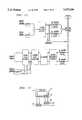
- FIG. 12depicts the entire, full duplex, modem constructed in accordance with the depictions of FIGS. 9 and 11. More specifically, a transmitter section (FIG. 9) is coupled with a receiver section (FIG. 11) through hybrid 300 and subtractor 310. Subtractor 3 10 cooperates with echo canceller 320 in the conventional way to subtract unwanted signals from the signal applied to demodulator 210. For sake of simplicity, echo canceller 320 is shown to connected to the output of orthogonal modulator 90, and in analog embodiments of element 320 this is perfectly satisfactory. However, in digital embodiments it is well known that efficiencies can be realized by having the echo canceller be responsive to the outputs of mapper 60, where the signal rate is much lower.
- FIG. 13An improvement which incorporates the principles disclosed herein is shown in FIG. 13. It may be noted that some of the elements in FIG. 13 are designated by different labels; such as "Hilbert passband filter", which corresponds to a modulator, etc. These are circuits that attain the desired results through somewhat different calculations and are well known to persons skilled in the modem art.
- the echo cancelingis performed, as in all modems, during a training period, when the far end signal source is silent and the echo canceller is adapted to minimize the output of subtractor 310.
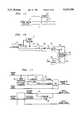
- the input to element 50can be a sampled analog signal, as well as an unsampled analog signal. It has also been disclosed above that when element 50 is a 1-to-2 mapper (as compared to 1-to-N mapper) and the desired output of element 50 is pairs of a sampled analog signal, the pairs of analog samples can be derived by simply delaying the incoming analog signal by 1/B and sampling both the delayed and the undelayed versions at rate B. This provides sample pairs that correspond to adjacent samples of the original analog signal sampled at rate 1/2B seconds. Actually, privacy of the communication is enhanced when the samples are not adjacent, and FIG. 14 presents one approach for deriving pairs from non-adjacent samples.
- Itbasically includes an input register 55 for storing K analog samples that arrive at rate 2B, a scrambling network 56 that scrambles the outputs of register 55 and develops K outputs, and registers 57 and 58 that are responsive to the outputs of network 56.
- Registers 57 and 58store K/2 analog samples every K/2B seconds and output the stored samples at rate 1/2B seconds.
- Scrambling network 56may be simply a cross-connect field.
- Another approach for enhancing privacyentails modifying the gain and phase of the analog signals that are sent. This is akin to operating on, or transforming, the signal components that form the signal vector which is added to the constellation symbols.
- the transformingmay be in accordance with the signal characteristics, or it may simply be following a pseudo-random sequence.
- FIG. 15depicted in FIG. 15, where register 72 receives analog signal sample pairs and directs each member of a pair to a different multiplier (73 and 74).
- Multipliers 73 and 74modify the applied signal samples in accordance with corresponding coefficients that are received from pseudo-random generator 71, resulting in a pair of modified signal samples that are applied to mapper 50. Additional teachings of this technique are found in U.S. Pat. No. 4,124,516, issued May 8, 1990, to G. Bremer and W. Betts.
- the receiverought to include a pseudo-random generator that is synchronized to generator 71 in order to properly decode the analog signal.
- the FIG. 15 circuitcan be incorporated in a receiver (such as the FIG. 11 receiver) within the de-mapper that develops the analog signal. Synchronization of the FIG. 15 circuit in the receiver is achieved via synchronization information that is sent by the transmitter as "side information".
- Characterizing the enhancement more generally, modifying the input signal based on the input signal's characteristicsis a general enhancement of the embodiments disclosed herein.
- the signal's amplitudefor example, can be dynamically modified to enhance the attainable signal to noise ratio.
- the dynamic scaling of the signalcan be communicated to the receiver in the form of "side information" either on the digital channel, or on the analog channel (for example, via one of the channels described in connection with the FIG. 9 embodiment). This is depicted in FIG. 16, where signal processor 75 precedes switch 32. Processor 75 modifies the signal applied to switch 32 and also provides the aforementioned side information that is applied to A/D converter bank 30.
- Still another way to modify the signalis to control its dynamic range through automatic gain control (AGC) which may be effected in conventional ways.
- AGCautomatic gain control
- Yet another way to modify the signalis to encode it, and that includes, for example, the entire field of predictive encoding.
- the objectis to predict the present signal from past signals and to transmit only the error, or residue, signal; that is, the signal that represents the deviation of the true signal from the predicted signal. It is expected, of course, that with good prediction the residue signal will be small.
- An arrangement that creates only small residue signalsallows the residue signals to be amplified (in a fixed manner or dynamically), achieving thereby good signal resolution and high noise immunity.
- the residue signal sample, e(n),is typically developed by the calculation:
- the number of coefficientsis a designer's choice, and that the number of coefficients can also be a function of signal characteristics. For some signal characteristics the number of coefficients may be two, for others it may be three, etc. Also, the values of the coefficients may be fixed (and set in accordance with historical determinations) or variable, based on considerations such as short term history of the signal, the current number of symbols in the constellation, etc.
- Processor 75 of FIG. 16may be employed to perform the selected encoding. More specifically, processor 75 may perform the function of a linear prediction coefficient generator that is sensitive to the characteristics of the input signal, and also perform the function of the augmentation filter. The coefficients developed by the linear predictive coefficient generator portion of processor 75 delivers the coefficients as side information to the A/D converter block, to be transmitted to the receiver and used therein in accordance with the equation
- FIG. 17presents a block diagram of the transmitter and receiver portions that handle the linear predictive coding (elements 65-60).
- the blocks marked “svd system”represent the receiver and transmitter portions of the modem embodiments (svd modem) disclosed above (e.g. FIG. 13).
- the "analog" input that enters orthogonal modulator 90can be filtered to pre-emphasize the high frequencies and, correspondingly, the "analog" output of subtractors 250 and 260 can be filtered to remove the pre-emphasis.
- the pre-emphasiscan be effected, for example, within the A/D converter 30 or even prior thereto, such as in pre-emphasis filter 20 shown in FIG. 12.
- the filteringcan be done while the "analog" signal is truly analog, or it could be done when the "analog” signal is represented digitally--such as when the transmitter and receiver sections are implemented with digital hardware.
- One aspect of the embodiments described above which employ a sampling process for the analog signal applied to mapper 50is the limitation on the highest frequency that may be included in the applied signal in accordance with Nyquist's criteria. Stated in other words, regardless of the bandwidth offered by the communications network, a decision to sample the incoming signal at the symbol rate of mapper 60 places a limit on the upper frequency of the sampled signal. In some applications, such as in speech applications, it may be desirable to transmit higher frequency signals even if the cost of achieving that capability is a forgoing of some low frequencies.
- This capabilityis realized by frequency shifting. That is, the speech signal is bandlimited, a preselected portion of the low frequency band is deleted, the resulting bandlimited signal is shifted downward, and the shifted signal is sampled.
- a number of implementations described aboverequire transmission of "side information" to the receiver. Also, as described above, this information can be sent on the analog channel or on the digital channel.
- the transmitterSince any sequence of bits chosen for the command sequence could also appear in the customer data bit stream, a safeguard method is used to ensure that instances of the command sequence which do appear in customer data are not interpreted as true command sequences.
- the input bit streamis monitored for instances of the command sequence in the customer data.
- the transmitterinserts a duplicate sequence immediately following the original.
- the input bit streamis again monitored for instances of the command sequence. If a command sequence is detected, the bit stream immediately following is checked for a duplicate instance of the same sequence. If such a duplicate is detected, indicating that the original sequence is in the customer data and not a true command flag, the receiver deletes the duplicate sequence from the data stream and continues monitoring. If, however, no duplicate is detected, the sequence is a true control flag. The receiver removes both the command sequence and the following side information from the main channel bit stream and routes the side information to its appropriate destination.
- each instanceis treated separately, with a duplicate instance inserted following the original.
- each pair of instancesis treated separately, with the second in the pair discarded.
- the outputwill consist of one half of the number of instances in the customer data stream and no side information. If an odd number n of instances is detected, the output will consist of (n-1)/2 instances in the output data stream and routing of side information in the receiver which is indicated by the last (unduplicated) command sequence.
- FIG. 18shows an arrangement where different signal spaces are employed at different times.
- the different signals spacescan be used at preselected times, or their use can be application dependent.
- the transmitter section of FIG. 18includes a transmitter signal space selector switch 410, a data-only signal space coder 411, an analog-only signal space coder 412, an analog & data signal space coder 413, and a dual-use signal space coder 414.
- the receiver sectionincludes a receiver signal space selector switch 420, a data-only signal space decoder 421, an analog-only signal space decoder 422, an analog & data signal space decoder 423, and a dual-use-signal space decoder 424.
- the data-only coder 411corresponds to the FIG. 6 coder with no input at line 51.
- the analog-only coder 412corresponds to the FIG. 6 coder with no input at line 61.
- the analog & digital coder 413corresponds to the FIG. 6 coder as described above, and the dual-use coder 414 is a coder where the symbols of line 61 in FIG. 6 are applied to only one of the orthogonal modulators, and the signals of line 51 in FIG. 6 are applied only to the other of the orthogonal modulators.
- the signals space changescan be planned apriori such as at predetermined symbol times (e.g., with symbol counter 415 and selector 416).
- the signal spacesneed not be the same in the two communication directions. All such signaling is effected through "hand shaking" protocols between the communicating modems; which in the example shown in FIG. 16, is merely a synchronization between TX Symbol counter 416 and RX Symbol Counter 426.
- FIG. 30illustrates the arrangement for accomplishing these tasks, with a controller 610 that is connected to a modem 600.
- controller 610is arranged to interrupt the normal program flow in modem 600 whenever the right conditions occur.
- controller 610senses the condition and forwards an interrupt to the microprocessor within modem 600. Modem 600 then goes into a "control mode” which reads the instructions provided to modem 600 by controller 610.
- controller 610specifies an "off hook” condition, modem 600 is reconfigured to pass through the signals arriving at the analog port directly to the telephone network. This can be accomplished in modem 600 by providing a separate signal path that is enabled, or by conditioning the various elements in the signal path to achieve the same end results.
- dial tonescan then flow to the telephone central office and establish a connection.
- modem 600When a connection is established to a far end customer, modem 600 sends a tone, identifying itself as a) a modem and b) an svd modem. Once a connection to the far end equipment is established and the far end equipment identifies itself as an svd modem, then modem 600 assumes its svd modem architecture. If the far end equipment identifies itself as a non-svd modem, then modem 600 can establish itself as a conventional modem connecting its digital port to the far end equipment. Lastly, if the far end equipment identifies itself as a conventional telephone, modem 600 remains in its "short circuited" mode.
- Dismantling a connectionis at least as easy.
- An "on hook” conditionis detected by controller 610 and, if there is no “conversation” established on the data side, controller 610 signals modem 600 to turn itself off.
- controller 610can be responsive to touch tone sequence, included the "#" and the "*" tones.
- DLE shielding signalingcan be employed. In this manner, once only a digital path is maintained, the digital signal source can effect a "disconnect".
- FIG. 30also depicts an enhancement for a modem failure mode. This enhancement would advantageously be incorporated in all uses of the disclosed modem where connection to a telephone function is desired even in the absence of local power.
- FIG. 30includes a pair of leads from the analog side of the modem to a pair of relay contacts 630.
- Relay contacts 630are arranged to connect the telephone network leads to the telephone network port of modem 600 when modem 600 is operational, or to the analog port of modem 600, otherwise.
- the relay coil that operates contacts 630may simply be responsive to the leads that power modem 600, or to a "status OK" output lead of the modem.
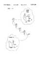
- FIG. 22depicts such an arrangement employing a modem as disclosed above.
- a customercalls in to the Call Center and through the Call Center is connected to the home agent over the analog channel.
- the home agentis connected through the data channel to the computer in the Call Center.
- the home agentinteracts simultaneously with both the customer and the Call Center's computer.
- the voice channelis connected to a customer outside the Call Center. Connection of the home agent to its home base location (via the Call Center or any other place of business) for both voice and data is achievable with the modem disclosed herein.
- One examplemay be in connection with the extending of credit, or providing physical access to a building.
- the usermay normally use a credit card that communicates digitally with a central facility. If something goes awry and the control system that communicates with the credit card declines to extend credit (such as when paying for a purchase) or denies access to a building, the analog channel can be automatically activated to allow the user to communicate with an individual who can overrule the system's actions.
- a security systemcan automatically connect both the digital and the analog channel, so that both digital and analog information can be used for determining whether the requested action should be taken.
- the analog data that is thus obtainedcan be used to determine whether correct answers were given to a sequence of questions (e.g., "please state your mother's maiden name") or to analyze voice characteristics to determine even more assuredly the authenticity of the user.
- the modem disclosed hereinis incorporated in the game device. This arrangement is depicted in FIG. 23.
- television setsreceive their input from an antenna, or from a coax cable.
- televisionscan receive input from a fiber cable --providing a much increased bandwidth--, as well as from a conventional telephone tip-ring cord--providing a much reduced bandwidth.
- the cable service providersprovide a two directional channel path, through which customers can actively interact with the cable service providers.
- FIG. 24depicts an embodiment which integrates telephony, data communication and video control for a conventional telephone cord connection to a television.
- element 430is the modem disclosed herein. It is connected to the telephone network via line 431.
- the analog port of modem 430 and the digital port of modem 430are connected to video card 440 via hybrids 432 and 433.
- Modem 430receives image and voice signals from line 431, card 440 combines the received signals, forms a composite signal and applies the composite signal to television 450.
- a corded phone, or a speakerphonecan, of course, be used in connection with the FIG. 24 arrangement, but in FIG. 24 a cordless telephone 460 is shown that communicates with line 431 through the cordless base station electronics 465.
- the arrangement of FIG. 24contemplates that the voice signals would be applied to the telephone line through hybrid 432 and modem 430.
- the touch tone signals, which are the control signals sent to the cable service providerare converted to digital form in block 434 and applied to the telephone line throughout hybrid 433 and modem 430.
- Hybrids 432 and 433merely insure that the data sent to the telephone line does not interfere with the information sent to the television.
- the control signalscan be embedded in the voice signal and deciphered by the cable service provider at the distant end, then the connection between block 465 and the digital port of modem 430 can be severed and elements 433 and 434 can be deleted.
- FIG. 24can be used in various applications such as home shopping, text-book like learning, etc.
- still imagesare communicated to the television set and voice is sent concurrently through the audio channel.
- the userresponds, as necessary, over either the analog or the digital channel (such as to place an order or to answer a question).
- the above-described arrangement that contemplates use of a telephone cablecan be easily extended to wide bandwidth cables 431. All that is needed is a frequency division splitter interposed between the cable and modem 430.
- the high bandwidth signals that are destined to the TVcan be sent directly to the TV, while the low bandwidth communication channel is sent to modem 430.
- controller 434which is arranged to apply control signals to modem 430, causing modem 430 to react to the control signals in the appropriate manner.
- controller 434can merely send an appropriate interrupt signal to the controller.
- notepad computer 500is adapted to receive a PCMCIA modem 510 that is constructed in accordance with the disclosure herein, and this modem includes a voice port 511.
- the PCMCIA modemalso includes a conventional RJ-11 sockets (512, 513) for plugging in a conventional telephone.
- the plugged-in phoneprovides an audio path, but that path is not limited to speech. It can be the conduit sending graphic information to a remote computer, for example.
- device 500need not be a computer. It can merely comprise the wireless transmission and receiving circuitry that interacts with modem 510, offering a digital port for whatever use may be desired.
- modem 510can be a "wireless svd modem" can be placed on a dashboard of a car that is being maintained, the digital port would be connected to the analysis port on the car's electronic system, the analog port would be connected to a telephone instrument and the car mechanic would then be able to converse with a service center in the manner bed in connection with FIGS. 19-21.
- FIGS. 26-29depict a telephone with video capability that includes such a modem, a simple telephone that includes such a modem and a socket for data interface, a fax machine that includes such a modem, and a computer that includes such a modem.
- the video telephone of FIG. 26may be connected to a wall outlet (as depicted) or it may be cellular.
- the computer of FIG. 28may include all circuitry that is needed for the telephone function, leaving only the hand set to be connected to the RJ-11 plug at the side of the computer.
- hands free Speakerphone capabilitycan be incorporated. It may be noted that the modem shown in FIG. 28 is depicted as a box within the computer but, more likely, it will be constructed on a printed circuit board and plugged into one of the standard open slots that are available in the computer.
- the RJ11 connector that is depicted in the drawing and into which a telephone on the telephone hand-set would be plugged inmight be on the modem's printed circuit board, or it might be positioned in the PC's housing (as shown in the FIG.) for easier access by the user.
- the telephone shown in FIG. 29can include a toggle switch, or may include a programmed key pad that dictates whether the telephone acts as a POTS ("plain old telephone service") phone or a phone having SVD capabilities. Alteratively, or additionally, the telephone of FIG. 29 may include a switch or a key pad option (e.g., #S, for scrambling) to incorporate a privacy scrambling feature in accordance with the systems shown in FIGS. 14 and 15.
- a switch or a key pad optione.g., #S, for scrambling
- FIG. 24presented an arrangement for multi-media uses of the modem disclosed herein.
- Another multi-media usedepicted in FIG. 31, may be devoted to interactive text/speech arrangements.
- the userspeaks to a computer 510 via the analog path comprising line 501, SVD system 502, network 503, SVD system 504 and speech recognizer 506.
- the computerrecognizes a request for text (or any other digital output) and provides that output via line 507, elements 504, 503, 502 and text output converter 509.
- FIG. 31includes a text-to-speech converter 509 in the analog path from the computer to the user.
- Elements 506 and 509are preferably at the computer end of the analog communication path because its is expected that one computer would serve the needs of many users. Therefore, a more sophisticated (and, typically, more expensive) speech recognizer and text-to-speech converter can be justified economically.
- the modem disclosed hereinis used to effectively communicate with a hearing-impaired person, without knowing beforehand that the called party is hearing-impaired, and without the assistance of an attendant.
- FIG. 32a who caller who is connected to an hearing-impaired person might encounter an arrangement as illustrated in FIG. 32.
- the FIG. 32 arrangementmerely includes a simple ring detection circuit 520. It provides an alert signal to the hearing-impaired person in whatever manner may be desired by the customer; e.g. flashing lights.
- the hearing-impaired personactivates the digital path and begins conversing via the alternate, digital, path by simply typing information.
- the analog pathis still active, so that a non-hearing-impaired person can join in the conversation, or merely continue the conversation in the conventional manner.
- assistance to customers who are visually impaired rather than hearing-impairedcan also be provided with the modem disclosed herein.
- ATMsautomated teller machines
- the visually-impaired personcan activate an audio path to an ATM agent who could execute the desired transaction, allowing all activities to take place verbally, save entering the password into the ATM--which would be done through the digital path to maintain security.
- Conventional telephone answering machinesinclude only an analog port, and record the received information with the assumption that the source is analog.
- Some answering machinesinclude multiplex circuitry for responding to one of two incoming lines (e.g. the AT&T 1501 answering machine) and some convert the analog signals to digital format, compress it, and store the digital result. None, however, respond to an analog channel and to a digital channel concurrently.
- the answering machine illustrated in FIG. 33responds to both digital and analog input signals, effectively concurrently. More particularly, it responds, and stores in one memory, the multiple information streams which appear on line 531 in the signal format disclosed herein. This may include alternating analog and digital signals, and it may include concurrent analog and digital signals.
- Line 531is applied in FIG. 33 to SVD system 532 and the two signals streams developed thereby are applied to answer device 533.
- device 533may comprise a conventional "analog" telephone answering machine that is responsive to the analog signal, and a conventional "digital" answering machine (sans the A/D converter circuitry) that is responsive to the digital signal.
- device 533comprises a memory 536, an A/D converter 535, and a controller 534 responsive to the digital signal derived from A/D converter 535 and to the digital signal derived from the SVD system.
- Controller 534stores the analog information at the top portion of memory 536, advancing "downward” into the memory (from the current point of previously recorded information which must not be erased), and stores the digital information at the bottom portion of the memory, advancing "upward” into the memory (from the current point of previously recorded information that must not be erased).
- Controller 534that accomplishes the above control is completely conventional, employing a few registers, multiplex circuits, and store-control circuitry.
Landscapes
- Engineering & Computer Science (AREA)
- Computer Networks & Wireless Communication (AREA)
- Signal Processing (AREA)
- Digital Transmission Methods That Use Modulated Carrier Waves (AREA)
- Telephonic Communication Services (AREA)
Abstract
Description
e(n)=x(n)-a.sub.1 x(n-1)-a.sub.2 x(n-2)-a.sub.3 x(n-3) . . .
y(n)=e(n)+a.sub.1 y(n-1)+a.sub.2 y(n-2)+a.sub.3 y(n-3) . . .
Claims (16)
Priority Applications (8)
| Application Number | Priority Date | Filing Date | Title |
|---|---|---|---|
| US08/076,520US5537436A (en) | 1993-06-14 | 1993-06-14 | Simultaneous analog and digital communication applications |
| CA002124730ACA2124730A1 (en) | 1993-06-14 | 1994-05-31 | Simultaneous analog and digital communication applications |
| EP94304186AEP0631421A1 (en) | 1993-06-14 | 1994-06-10 | Simultaneous analog and digital communication applications |
| KR1019940013570AKR950002312A (en) | 1993-06-14 | 1994-06-13 | Analog and Digital Simultaneous Modem |
| JP6153112AJPH0799512A (en) | 1993-06-14 | 1994-06-13 | Modem |
| FI942784AFI942784A7 (en) | 1993-06-14 | 1994-06-13 | Applications of simultaneous analog and digital transmission |
| IL10999894AIL109998A (en) | 1993-06-14 | 1994-06-13 | Simultaneous analog and digital communication applications |
| CN94106645ACN1099209A (en) | 1993-06-14 | 1994-06-13 | Simultaneous analog and digital communication applications |
Applications Claiming Priority (1)
| Application Number | Priority Date | Filing Date | Title |
|---|---|---|---|
| US08/076,520US5537436A (en) | 1993-06-14 | 1993-06-14 | Simultaneous analog and digital communication applications |
Publications (1)
| Publication Number | Publication Date |
|---|---|
| US5537436Atrue US5537436A (en) | 1996-07-16 |
Family
ID=22132533
Family Applications (1)
| Application Number | Title | Priority Date | Filing Date |
|---|---|---|---|
| US08/076,520Expired - Fee RelatedUS5537436A (en) | 1993-06-14 | 1993-06-14 | Simultaneous analog and digital communication applications |
Country Status (8)
| Country | Link |
|---|---|
| US (1) | US5537436A (en) |
| EP (1) | EP0631421A1 (en) |
| JP (1) | JPH0799512A (en) |
| KR (1) | KR950002312A (en) |
| CN (1) | CN1099209A (en) |
| CA (1) | CA2124730A1 (en) |
| FI (1) | FI942784A7 (en) |
| IL (1) | IL109998A (en) |
Cited By (90)
| Publication number | Priority date | Publication date | Assignee | Title |
|---|---|---|---|---|
| US5684825A (en)* | 1994-03-23 | 1997-11-04 | Paradyne Corporation | Independently switched voice and data calls using a simultaneous voice and data modem |
| WO1997041701A1 (en)* | 1996-04-26 | 1997-11-06 | Paradyne Corporation | Cellular phone interface for a simultaneous voice/data modem |
| US5719922A (en)* | 1994-06-24 | 1998-02-17 | Paradyne Corporation | Simultaneous voice/data answering machine |
| US5771278A (en)* | 1993-12-27 | 1998-06-23 | Cirrus Logic, Inc. | Method and apparatus for minimizing system oscillations caused by acoustical coupling |
| US5835480A (en)* | 1996-10-15 | 1998-11-10 | Chennakeshu; Sandeep | Circuitry and method for simultaneously transmitting voice and data information |
| US5844944A (en)* | 1993-06-14 | 1998-12-01 | Paradyne Corporation | Simultaneous analog and digital communication using partitioning of bits into words |
| US5878077A (en)* | 1995-10-10 | 1999-03-02 | Paradyne Corporation | Apparatus for high-speed simultaneous voice/data communications |
| US5901202A (en)* | 1996-10-11 | 1999-05-04 | At&T Corp | Method for initiating a telephone call on a remote line |
| US5935099A (en) | 1992-09-09 | 1999-08-10 | Sims Deltec, Inc. | Drug pump systems and methods |
| US5949763A (en)* | 1997-07-17 | 1999-09-07 | Ameritech Corporation | Method and apparatus for providing broadband access conferencing services |
| US6046762A (en)* | 1997-04-01 | 2000-04-04 | Cosmocom, Inc. | Multimedia telecommunication automatic call distribution system |
| US6108388A (en)* | 1995-02-07 | 2000-08-22 | France Telecom | Iterative-structure digital signal reception device, and module and method therefor |
| US6141376A (en)* | 1997-04-01 | 2000-10-31 | Lsi Logic Corporation | Single chip communication device that implements multiple simultaneous communication channels |
| US6173044B1 (en)* | 1996-02-06 | 2001-01-09 | International Business Machines Corporation | Multipoint simultaneous voice and data services using a media splitter gateway architecture |
| US6285671B1 (en) | 1999-04-22 | 2001-09-04 | Ameritech Corporation | Method and system for providing facsimile service over a digital subscriber line |
| WO2001071965A1 (en)* | 2000-03-17 | 2001-09-27 | Bridgewave Communications, Inc. | Signal communications system and method for noisy links |
| US6335936B1 (en) | 1999-04-22 | 2002-01-01 | Ameritech Corporation | Wide area communication networking |
| US6363346B1 (en)* | 1999-12-22 | 2002-03-26 | Ncr Corporation | Call distribution system inferring mental or physiological state |
| US6370149B1 (en) | 1998-07-20 | 2002-04-09 | Ameritech Corporation | Telecommunication system, method and subscriber unit for use therein |
| US6400815B1 (en) | 2000-05-23 | 2002-06-04 | At&T Corp. | Method and apparatus for subscriber line to telephone call distribution |
| US6411695B1 (en) | 1996-05-09 | 2002-06-25 | At&T Corporation | System and method for completing two calls using analog interface to telephone network |
| US6427007B1 (en) | 1996-05-09 | 2002-07-30 | At&T Corporation | System and method for completing a call while at least one call is established using analog interface to telephone network |
| US6434382B2 (en)* | 1998-07-27 | 2002-08-13 | Lucent Technologies Inc. | Cellular call processor having concurrent instances of call models to support mixed media communication connections |
| US20020141561A1 (en)* | 2000-04-12 | 2002-10-03 | Austin Logistics Incorporated | Method and system for self-service scheduling of inbound inquiries |
| US20030108048A1 (en)* | 1996-04-29 | 2003-06-12 | Kwok Timothy C. | Dynamic ATM connection management in a hybrid fiber-coax cable network |
| US6594505B1 (en)* | 1998-07-10 | 2003-07-15 | Nec Corporation | Mobile telephone system capable of coping with a variety of mobile radio telephone systems by a single mobile radio telephone |
| US6614783B1 (en) | 1997-04-01 | 2003-09-02 | Cosmocom, Inc. | Multimedia telecommunication automatic call distribution system using internet/PSTN call routing |
| US6665799B1 (en)* | 1999-04-28 | 2003-12-16 | Dvi Acquisition Corp. | Method and computer software code for providing security for a computer software program |
| US20040008616A1 (en)* | 2002-07-08 | 2004-01-15 | Samsung Electronics Co., Ltd | Apparatus and method for transmitting and receiving side information about selective mapping in an orthogonal frequency division multiplexing communication system |
| US20040044516A1 (en)* | 2002-06-03 | 2004-03-04 | Kennewick Robert A. | Systems and methods for responding to natural language speech utterance |
| US6760727B1 (en) | 1999-07-30 | 2004-07-06 | Convergys Cmg Utah, Inc. | System for customer contact information management and methods for using same |
| US6773291B1 (en) | 1993-11-12 | 2004-08-10 | Intel Corporation | Compliant communications connectors |
| US20040179672A1 (en)* | 2001-07-09 | 2004-09-16 | Austin Logistics Incorporated | System and method for updating contact records |
| US20040193420A1 (en)* | 2002-07-15 | 2004-09-30 | Kennewick Robert A. | Mobile systems and methods for responding to natural language speech utterance |
| US20050094718A1 (en)* | 2002-12-20 | 2005-05-05 | Bridgewave Communications, Inc. | Wideband digital radio with transmit modulation cancellation |
| US6917624B1 (en) | 1997-11-10 | 2005-07-12 | Sbc Properties, L.P. | Method and apparatus for providing a derived digital telephone voice channel |
| US7031749B1 (en)* | 1999-03-26 | 2006-04-18 | Nec Corporation | Software portable telephone |
| US7054434B2 (en) | 2001-07-09 | 2006-05-30 | Austin Logistics Incorporated | System and method for common account based routing of contact records |
| US7074061B1 (en) | 1993-11-12 | 2006-07-11 | Intel Corporation | Versatile communications connectors |
| USRE39165E1 (en) | 1997-06-13 | 2006-07-11 | Pctel, Inc. | Method and apparatus for training linear equalizers in a PCM modem |
| US7103173B2 (en) | 2001-07-09 | 2006-09-05 | Austin Logistics Incorporated | System and method for preemptive goals based routing of contact records |
| US7142662B2 (en) | 2000-07-11 | 2006-11-28 | Austin Logistics Incorporated | Method and system for distributing outbound telephone calls |
| US20070033005A1 (en)* | 2005-08-05 | 2007-02-08 | Voicebox Technologies, Inc. | Systems and methods for responding to natural language speech utterance |
| US20070038436A1 (en)* | 2005-08-10 | 2007-02-15 | Voicebox Technologies, Inc. | System and method of supporting adaptive misrecognition in conversational speech |
| US20070036169A1 (en)* | 1996-11-01 | 2007-02-15 | Sbc Properties, L.P. | Telecommunication system, method and subscriber unit for use therein |
| US20070055525A1 (en)* | 2005-08-31 | 2007-03-08 | Kennewick Robert A | Dynamic speech sharpening |
| US20070153726A1 (en)* | 2005-12-30 | 2007-07-05 | Idan Bar-Sade | Digital microwave radio link with adaptive data rate |
| US7347836B2 (en) | 1992-09-09 | 2008-03-25 | Smiths Medical, Inc. | Drug pump systems and methods |
| US7502460B2 (en) | 2006-11-20 | 2009-03-10 | Austin Logistics Incorporated | Method and system for distributing outbound telephone calls |
| US20090150156A1 (en)* | 2007-12-11 | 2009-06-11 | Kennewick Michael R | System and method for providing a natural language voice user interface in an integrated voice navigation services environment |
| US20100194899A1 (en)* | 2009-01-30 | 2010-08-05 | Techwell, Inc. | Mixed format media transmission systems and methods |
| US7818176B2 (en) | 2007-02-06 | 2010-10-19 | Voicebox Technologies, Inc. | System and method for selecting and presenting advertisements based on natural language processing of voice-based input |
| US20110081872A1 (en)* | 2005-12-30 | 2011-04-07 | Bridgewave Communications, Inc. | Digital Microwave Radio Link with a Variety of Ports |
| US7949529B2 (en) | 2005-08-29 | 2011-05-24 | Voicebox Technologies, Inc. | Mobile systems and methods of supporting natural language human-machine interactions |
| US20110150255A1 (en)* | 2009-12-22 | 2011-06-23 | Starkey Laboratories, Inc. | Fm radio system for digital and analog communications for hearing assistance devices |
| US8023580B2 (en) | 1997-12-05 | 2011-09-20 | Bremer Gordon F | System and method of communication using at least two modulation methods |
| US8073681B2 (en) | 2006-10-16 | 2011-12-06 | Voicebox Technologies, Inc. | System and method for a cooperative conversational voice user interface |
| US8133197B2 (en) | 2008-05-02 | 2012-03-13 | Smiths Medical Asd, Inc. | Display for pump |
| US8149131B2 (en) | 2006-08-03 | 2012-04-03 | Smiths Medical Asd, Inc. | Interface for medical infusion pump |
| US8250483B2 (en) | 2002-02-28 | 2012-08-21 | Smiths Medical Asd, Inc. | Programmable medical infusion pump displaying a banner |
| US8326637B2 (en) | 2009-02-20 | 2012-12-04 | Voicebox Technologies, Inc. | System and method for processing multi-modal device interactions in a natural language voice services environment |
| US8435206B2 (en) | 2006-08-03 | 2013-05-07 | Smiths Medical Asd, Inc. | Interface for medical infusion pump |
| US8504179B2 (en) | 2002-02-28 | 2013-08-06 | Smiths Medical Asd, Inc. | Programmable medical infusion pump |
| US8589161B2 (en) | 2008-05-27 | 2013-11-19 | Voicebox Technologies, Inc. | System and method for an integrated, multi-modal, multi-device natural language voice services environment |
| US8858526B2 (en) | 2006-08-03 | 2014-10-14 | Smiths Medical Asd, Inc. | Interface for medical infusion pump |
| US8908838B2 (en) | 2001-08-23 | 2014-12-09 | Ultratec, Inc. | System for text assisted telephony |
| US8917821B2 (en) | 2005-06-29 | 2014-12-23 | Ultratec, Inc. | Device independent text captioned telephone service |
| US8954336B2 (en) | 2004-02-23 | 2015-02-10 | Smiths Medical Asd, Inc. | Server for medical device |
| US8965707B2 (en) | 2006-08-03 | 2015-02-24 | Smiths Medical Asd, Inc. | Interface for medical infusion pump |
| US9171541B2 (en) | 2009-11-10 | 2015-10-27 | Voicebox Technologies Corporation | System and method for hybrid processing in a natural language voice services environment |
| US9305548B2 (en) | 2008-05-27 | 2016-04-05 | Voicebox Technologies Corporation | System and method for an integrated, multi-modal, multi-device natural language voice services environment |
| US9432172B2 (en) | 1997-12-05 | 2016-08-30 | Rembrandt Wireless Technologies, Lp | System and method of communication using at least two modulation methods |
| US9502025B2 (en) | 2009-11-10 | 2016-11-22 | Voicebox Technologies Corporation | System and method for providing a natural language content dedication service |
| US9626703B2 (en) | 2014-09-16 | 2017-04-18 | Voicebox Technologies Corporation | Voice commerce |
| US9747896B2 (en) | 2014-10-15 | 2017-08-29 | Voicebox Technologies Corporation | System and method for providing follow-up responses to prior natural language inputs of a user |
| US9898459B2 (en) | 2014-09-16 | 2018-02-20 | Voicebox Technologies Corporation | Integration of domain information into state transitions of a finite state transducer for natural language processing |
| US10331784B2 (en) | 2016-07-29 | 2019-06-25 | Voicebox Technologies Corporation | System and method of disambiguating natural language processing requests |
| US10389876B2 (en) | 2014-02-28 | 2019-08-20 | Ultratec, Inc. | Semiautomated relay method and apparatus |
| US10431214B2 (en) | 2014-11-26 | 2019-10-01 | Voicebox Technologies Corporation | System and method of determining a domain and/or an action related to a natural language input |
| US10491746B2 (en) | 2004-02-18 | 2019-11-26 | Ultratec, Inc. | Captioned telephone service |
| US10614799B2 (en) | 2014-11-26 | 2020-04-07 | Voicebox Technologies Corporation | System and method of providing intent predictions for an utterance prior to a system detection of an end of the utterance |
| US10682460B2 (en) | 2013-01-28 | 2020-06-16 | Smiths Medical Asd, Inc. | Medication safety devices and methods |
| US10748523B2 (en) | 2014-02-28 | 2020-08-18 | Ultratec, Inc. | Semiautomated relay method and apparatus |
| US10878721B2 (en) | 2014-02-28 | 2020-12-29 | Ultratec, Inc. | Semiautomated relay method and apparatus |
| US10917519B2 (en) | 2014-02-28 | 2021-02-09 | Ultratec, Inc. | Semiautomated relay method and apparatus |
| US11258900B2 (en) | 2005-06-29 | 2022-02-22 | Ultratec, Inc. | Device independent text captioned telephone service |
| US11349623B2 (en) | 2017-09-18 | 2022-05-31 | Fraunhofer-Gesellschaft zur Förderung der angewandten Forschung e.V. | Reliable and low-latency transmission of data via a voice channel in a communication network |
| US11539900B2 (en) | 2020-02-21 | 2022-12-27 | Ultratec, Inc. | Caption modification and augmentation systems and methods for use by hearing assisted user |
| US11664029B2 (en) | 2014-02-28 | 2023-05-30 | Ultratec, Inc. | Semiautomated relay method and apparatus |
| US12335327B2 (en) | 2007-06-28 | 2025-06-17 | Voxer Ip Llc | Telecommunication and multimedia management method and apparatus |
Families Citing this family (3)
| Publication number | Priority date | Publication date | Assignee | Title |
|---|---|---|---|---|
| JP3140960B2 (en)* | 1996-04-05 | 2001-03-05 | 富士通株式会社 | Modem signal transmitting apparatus, modem signal transmitting method, modem signal receiving apparatus, modem signal receiving method, modem signal transmitting / receiving system, and modem signal transmitting / receiving method |
| CN101686215B (en)* | 2008-09-26 | 2012-10-17 | 西门子(中国)有限公司 | A signal coding modulation method and device |
| CN102307168B (en)* | 2011-08-06 | 2014-04-02 | 桂林市思奇通信设备有限公司 | Separation method and receiving device of digital broadcasting analog-to-digital (A/D) signal at frequency modulation (FM) broadcast band |
Citations (10)
| Publication number | Priority date | Publication date | Assignee | Title |
|---|---|---|---|---|
| US4512013A (en)* | 1983-04-11 | 1985-04-16 | At&T Bell Laboratories | Simultaneous transmission of speech and data over an analog channel |
| US4546212A (en)* | 1984-03-08 | 1985-10-08 | Crowder, Inc. | Data/voice adapter for telephone network |
| US4672602A (en)* | 1984-11-02 | 1987-06-09 | Itt Corporation | Control and routing system |
| US4757495A (en)* | 1986-03-05 | 1988-07-12 | Telebit Corporation | Speech and data multiplexor optimized for use over impaired and bandwidth restricted analog channels |
| US4891806A (en)* | 1987-09-18 | 1990-01-02 | Racal Data Communications Inc. | Constellation multiplexed inband secondary channel for voiceband modem |
| US4924516A (en)* | 1989-05-23 | 1990-05-08 | At&T Paradyne | Method and system for a synchronized pseudo-random privacy modem |
| US5081647A (en)* | 1989-01-06 | 1992-01-14 | American Telephone & Telegraph Company | Communication of a voice signal via continuous quadrature amplitude modulator |
| US5103227A (en)* | 1990-09-26 | 1992-04-07 | At&T Bell Laboratories | Modulus converter for fractional rate encoding |
| US5151972A (en)* | 1989-03-28 | 1992-09-29 | Lynx Automation, Inc. | Apparatus for automatically connecting terminal device to telephone lines |
| US5243629A (en)* | 1991-09-03 | 1993-09-07 | At&T Bell Laboratories | Multi-subcarrier modulation for hdtv transmission |
Family Cites Families (1)
| Publication number | Priority date | Publication date | Assignee | Title |
|---|---|---|---|---|
| JPH02295260A (en)* | 1989-05-10 | 1990-12-06 | Toshiba Corp | Modulator |
- 1993
- 1993-06-14USUS08/076,520patent/US5537436A/ennot_activeExpired - Fee Related
- 1994
- 1994-05-31CACA002124730Apatent/CA2124730A1/ennot_activeAbandoned
- 1994-06-10EPEP94304186Apatent/EP0631421A1/ennot_activeCeased
- 1994-06-13KRKR1019940013570Apatent/KR950002312A/ennot_activeWithdrawn
- 1994-06-13ILIL10999894Apatent/IL109998A/ennot_activeIP Right Cessation
- 1994-06-13JPJP6153112Apatent/JPH0799512A/enactivePending
- 1994-06-13FIFI942784Apatent/FI942784A7/ennot_activeApplication Discontinuation
- 1994-06-13CNCN94106645Apatent/CN1099209A/enactivePending
Patent Citations (10)
| Publication number | Priority date | Publication date | Assignee | Title |
|---|---|---|---|---|
| US4512013A (en)* | 1983-04-11 | 1985-04-16 | At&T Bell Laboratories | Simultaneous transmission of speech and data over an analog channel |
| US4546212A (en)* | 1984-03-08 | 1985-10-08 | Crowder, Inc. | Data/voice adapter for telephone network |
| US4672602A (en)* | 1984-11-02 | 1987-06-09 | Itt Corporation | Control and routing system |
| US4757495A (en)* | 1986-03-05 | 1988-07-12 | Telebit Corporation | Speech and data multiplexor optimized for use over impaired and bandwidth restricted analog channels |
| US4891806A (en)* | 1987-09-18 | 1990-01-02 | Racal Data Communications Inc. | Constellation multiplexed inband secondary channel for voiceband modem |
| US5081647A (en)* | 1989-01-06 | 1992-01-14 | American Telephone & Telegraph Company | Communication of a voice signal via continuous quadrature amplitude modulator |
| US5151972A (en)* | 1989-03-28 | 1992-09-29 | Lynx Automation, Inc. | Apparatus for automatically connecting terminal device to telephone lines |
| US4924516A (en)* | 1989-05-23 | 1990-05-08 | At&T Paradyne | Method and system for a synchronized pseudo-random privacy modem |
| US5103227A (en)* | 1990-09-26 | 1992-04-07 | At&T Bell Laboratories | Modulus converter for fractional rate encoding |
| US5243629A (en)* | 1991-09-03 | 1993-09-07 | At&T Bell Laboratories | Multi-subcarrier modulation for hdtv transmission |
Non-Patent Citations (20)
| Title |
|---|
| "A New Generation of Speech Plus Data Multiplexer", Conference on Communications and Equipment and Systems, Birmingham, England, Apr. 4-7, 1978, by N. N. Y. Shum et al, pp. 111-113. |
| "Adaptive Equalization and Phase Tracking for Simultaneous Analog/Digital Data Transmission", The Bell System Technical Journal, vol. 60, No. 9, Nov. 1981, by T. L. Lim and M. S. Mueller, pp. 2039-2063. |
| "Adaptive Noise Cancelling: Principles and Applications", Proceedings of the IEEE, vol. 63, No. 12, Dec. 1975, by B. Widrow et al, pp. 1692-1716. |
| "An Integrated Digital Subscribers Speech and Data Service", ICC Conf. Rec., vol. 3, Seattle, Washington, Jun. 8-12, 1980, by L. J. Stagg and D. Clothier, pp. 39.6.1-39.6.6. |
| "Frequency Domain Data Transmission using Reduced Computational Complexity Algorithms", ICASSP 80 Proc., Denver, Colorado, vol. 1, Apr. 9-11, 1980, by A. Peled and A. Ruiz, pp. 964-967. |
| "High Speed Digital and Analog Parallel Transmission Technique Over Single Telephone Channel", IEEE Transactions on Communications, vol. COM-30, No. 5, May 1982, by F. Akashi, Y. Sato and M. Eguchi, pp. 1213-1218. |
| "Method for superimposing Data on Amplitude-Modulated Signals", Electronics Letters, vol. 18, No. 9, Apr. 29, 1982, by Lockhart et al, pp. 379-381. |
| "Simultaneous Transmission of Speech and Data Using Code-Breaking Techniques", The Bell System Technical Journal, vol. 60, No. 9, Nov. 1981, by R. Steele and D. Vitello, pp. 2081-2105. |
| "Speech and Data Transmission in ACS Telephone Channels", Telecommunication & Radio Eng., vol. 30/31, Jul. 1976, by V. E. Bukhviner, pp. 66-70. |
| "Speech-band data modems", Electronics & Power, vol. 26, No. 9, by P. F. Adams, pp. 733-736. |
| A New Generation of Speech Plus Data Multiplexer , Conference on Communications and Equipment and Systems , Birmingham, England, Apr. 4 7, 1978, by N. N. Y. Shum et al, pp. 111 113.* |
| Adaptive Equalization and Phase Tracking for Simultaneous Analog/Digital Data Transmission , The Bell System Technical Journal , vol. 60, No. 9, Nov. 1981, by T. L. Lim and M. S. Mueller, pp. 2039 2063.* |
| Adaptive Noise Cancelling: Principles and Applications , Proceedings of the IEEE , vol. 63, No. 12, Dec. 1975, by B. Widrow et al, pp. 1692 1716.* |
| An Integrated Digital Subscribers Speech and Data Service , ICC Conf. Rec. , vol. 3, Seattle, Washington, Jun. 8 12, 1980, by L. J. Stagg and D. Clothier, pp. 39.6.1 39.6.6.* |
| Frequency Domain Data Transmission using Reduced Computational Complexity Algorithms , ICASSP 80 Proc. , Denver, Colorado, vol. 1, Apr. 9 11, 1980, by A. Peled and A. Ruiz, pp. 964 967.* |
| High Speed Digital and Analog Parallel Transmission Technique Over Single Telephone Channel , IEEE Transactions on Communications , vol. COM 30, No. 5, May 1982, by F. Akashi, Y. Sato and M. Eguchi, pp. 1213 1218.* |
| Method for superimposing Data on Amplitude Modulated Signals , Electronics Letters , vol. 18, No. 9, Apr. 29, 1982, by Lockhart et al, pp. 379 381.* |
| Simultaneous Transmission of Speech and Data Using Code Breaking Techniques , The Bell System Technical Journal , vol. 60, No. 9, Nov. 1981, by R. Steele and D. Vitello, pp. 2081 2105.* |
| Speech and Data Transmission in ACS Telephone Channels , Telecommunication & Radio Eng. , vol. 30/31, Jul. 1976, by V. E. Bukhviner, pp. 66 70.* |
| Speech band data modems , Electronics & Power , vol. 26, No. 9, by P. F. Adams, pp. 733 736.* |
Cited By (228)
| Publication number | Priority date | Publication date | Assignee | Title |
|---|---|---|---|---|
| US5935099A (en) | 1992-09-09 | 1999-08-10 | Sims Deltec, Inc. | Drug pump systems and methods |
| US7654976B2 (en) | 1992-09-09 | 2010-02-02 | Smiths Medical Asd, Inc. | Drug pump systems and methods |
| US7347836B2 (en) | 1992-09-09 | 2008-03-25 | Smiths Medical, Inc. | Drug pump systems and methods |
| US5844944A (en)* | 1993-06-14 | 1998-12-01 | Paradyne Corporation | Simultaneous analog and digital communication using partitioning of bits into words |
| US6832920B2 (en) | 1993-11-12 | 2004-12-21 | Intel Corporation | Compliant communications connectors |
| US7074061B1 (en) | 1993-11-12 | 2006-07-11 | Intel Corporation | Versatile communications connectors |
| US6773291B1 (en) | 1993-11-12 | 2004-08-10 | Intel Corporation | Compliant communications connectors |
| US6863554B1 (en) | 1993-11-12 | 2005-03-08 | Intel Corporation | PCMCIA compliant communications connectors |
| US5771278A (en)* | 1993-12-27 | 1998-06-23 | Cirrus Logic, Inc. | Method and apparatus for minimizing system oscillations caused by acoustical coupling |
| US5999597A (en)* | 1993-12-27 | 1999-12-07 | Cirrus Logic, Inc. | Method and apparatus for minimizing system oscillations caused by acoustical coupling |
| US5684825A (en)* | 1994-03-23 | 1997-11-04 | Paradyne Corporation | Independently switched voice and data calls using a simultaneous voice and data modem |
| US6236717B1 (en)* | 1994-06-24 | 2001-05-22 | Paradyne Corporation | Simultaneous voice/data answering machine |
| US5719922A (en)* | 1994-06-24 | 1998-02-17 | Paradyne Corporation | Simultaneous voice/data answering machine |
| US5711012A (en)* | 1994-08-01 | 1998-01-20 | Paradyne Corporation | Cellular phone interface for a simultaneous voice/data modem |
| US6108388A (en)* | 1995-02-07 | 2000-08-22 | France Telecom | Iterative-structure digital signal reception device, and module and method therefor |
| US5878077A (en)* | 1995-10-10 | 1999-03-02 | Paradyne Corporation | Apparatus for high-speed simultaneous voice/data communications |
| US6173044B1 (en)* | 1996-02-06 | 2001-01-09 | International Business Machines Corporation | Multipoint simultaneous voice and data services using a media splitter gateway architecture |
| WO1997041701A1 (en)* | 1996-04-26 | 1997-11-06 | Paradyne Corporation | Cellular phone interface for a simultaneous voice/data modem |
| US20030108048A1 (en)* | 1996-04-29 | 2003-06-12 | Kwok Timothy C. | Dynamic ATM connection management in a hybrid fiber-coax cable network |
| US6427007B1 (en) | 1996-05-09 | 2002-07-30 | At&T Corporation | System and method for completing a call while at least one call is established using analog interface to telephone network |
| US6539086B2 (en)* | 1996-05-09 | 2003-03-25 | At&T Corp. | System and method for completing two calls using analog interface to telephone network |
| US6411695B1 (en) | 1996-05-09 | 2002-06-25 | At&T Corporation | System and method for completing two calls using analog interface to telephone network |
| US5901202A (en)* | 1996-10-11 | 1999-05-04 | At&T Corp | Method for initiating a telephone call on a remote line |
| US5835480A (en)* | 1996-10-15 | 1998-11-10 | Chennakeshu; Sandeep | Circuitry and method for simultaneously transmitting voice and data information |
| US20070036169A1 (en)* | 1996-11-01 | 2007-02-15 | Sbc Properties, L.P. | Telecommunication system, method and subscriber unit for use therein |
| US7187686B1 (en) | 1996-11-01 | 2007-03-06 | Sbc Properties, B.P. | Telecommunication system, method and subscriber unit for use therein |
| US6141376A (en)* | 1997-04-01 | 2000-10-31 | Lsi Logic Corporation | Single chip communication device that implements multiple simultaneous communication channels |
| US6046762A (en)* | 1997-04-01 | 2000-04-04 | Cosmocom, Inc. | Multimedia telecommunication automatic call distribution system |
| US6614783B1 (en) | 1997-04-01 | 2003-09-02 | Cosmocom, Inc. | Multimedia telecommunication automatic call distribution system using internet/PSTN call routing |
| USRE39165E1 (en) | 1997-06-13 | 2006-07-11 | Pctel, Inc. | Method and apparatus for training linear equalizers in a PCM modem |
| US6370137B1 (en) | 1997-07-17 | 2002-04-09 | Ameritech Corporation | Method and apparatus for providing broadband access conferencing services |
| US20040252675A1 (en)* | 1997-07-17 | 2004-12-16 | Sbc Properties, L.P. | Method and apparatus for providing broadband access conferencing services |
| US5949763A (en)* | 1997-07-17 | 1999-09-07 | Ameritech Corporation | Method and apparatus for providing broadband access conferencing services |
| US8594115B2 (en) | 1997-11-10 | 2013-11-26 | At&T Intellectual Property I, L.P. | Distributing voice and data information over wireless and wireline networks |
| US20050271080A1 (en)* | 1997-11-10 | 2005-12-08 | Sbc Properties, L.P. | System and method for distributing voice and data information over wireless and wireline networks |
| US6917624B1 (en) | 1997-11-10 | 2005-07-12 | Sbc Properties, L.P. | Method and apparatus for providing a derived digital telephone voice channel |
| US7995601B2 (en) | 1997-11-10 | 2011-08-09 | At&T Intellectual Property I, L.P. | System and method for distributing voice and data information over wireless and wireline networks |
| US7525959B2 (en) | 1997-11-10 | 2009-04-28 | At&T Intellectual Property I, L.P. | System and method for distributing voice and data information over wireless and wireline networks |
| US8457228B2 (en) | 1997-12-05 | 2013-06-04 | Gordon F. Bremer | System and method of communication using at least two modulation methods |
| US9432172B2 (en) | 1997-12-05 | 2016-08-30 | Rembrandt Wireless Technologies, Lp | System and method of communication using at least two modulation methods |
| US8023580B2 (en) | 1997-12-05 | 2011-09-20 | Bremer Gordon F | System and method of communication using at least two modulation methods |
| US6594505B1 (en)* | 1998-07-10 | 2003-07-15 | Nec Corporation | Mobile telephone system capable of coping with a variety of mobile radio telephone systems by a single mobile radio telephone |
| US7126958B2 (en) | 1998-07-20 | 2006-10-24 | Sbc Properties, L.P. | Telecommunication system, method and subscriber unit for use therein |
| US20020110115A1 (en)* | 1998-07-20 | 2002-08-15 | Ameritech Corporation | Telecommunication system, method and subscriber unit for use therein |
| US6370149B1 (en) | 1998-07-20 | 2002-04-09 | Ameritech Corporation | Telecommunication system, method and subscriber unit for use therein |
| US20070140228A1 (en)* | 1998-07-20 | 2007-06-21 | Sbc Properties, L.P. | Telecommunication system, method and subscriber unit for use therein |
| US6434382B2 (en)* | 1998-07-27 | 2002-08-13 | Lucent Technologies Inc. | Cellular call processor having concurrent instances of call models to support mixed media communication connections |
| US7031749B1 (en)* | 1999-03-26 | 2006-04-18 | Nec Corporation | Software portable telephone |
| US20050074021A1 (en)* | 1999-04-22 | 2005-04-07 | Sbc Properties, L.P. | Wide area communication networking |
| US20020021691A1 (en)* | 1999-04-22 | 2002-02-21 | Ameritech Corporation | Method and system for providing facsimile service over a digital subscriber line |
| US6285671B1 (en) | 1999-04-22 | 2001-09-04 | Ameritech Corporation | Method and system for providing facsimile service over a digital subscriber line |
| US8238354B2 (en) | 1999-04-22 | 2012-08-07 | At&T Intellectual Property I, L.P. | Wide area communication networking |
| US7525990B2 (en) | 1999-04-22 | 2009-04-28 | At&T Intellectual Property I, L.P. | Wide area communication networking |
| US6335936B1 (en) | 1999-04-22 | 2002-01-01 | Ameritech Corporation | Wide area communication networking |
| US6665799B1 (en)* | 1999-04-28 | 2003-12-16 | Dvi Acquisition Corp. | Method and computer software code for providing security for a computer software program |
| US6760727B1 (en) | 1999-07-30 | 2004-07-06 | Convergys Cmg Utah, Inc. | System for customer contact information management and methods for using same |
| US6363346B1 (en)* | 1999-12-22 | 2002-03-26 | Ncr Corporation | Call distribution system inferring mental or physiological state |
| US7505531B1 (en) | 2000-03-17 | 2009-03-17 | Bridgewave Communications, Inc. | Signal communications system and method for noisy links |
| WO2001071965A1 (en)* | 2000-03-17 | 2001-09-27 | Bridgewave Communications, Inc. | Signal communications system and method for noisy links |
| US20020141561A1 (en)* | 2000-04-12 | 2002-10-03 | Austin Logistics Incorporated | Method and system for self-service scheduling of inbound inquiries |
| US6859529B2 (en) | 2000-04-12 | 2005-02-22 | Austin Logistics Incorporated | Method and system for self-service scheduling of inbound inquiries |
| US6400815B1 (en) | 2000-05-23 | 2002-06-04 | At&T Corp. | Method and apparatus for subscriber line to telephone call distribution |
| US7142662B2 (en) | 2000-07-11 | 2006-11-28 | Austin Logistics Incorporated | Method and system for distributing outbound telephone calls |
| USRE46420E1 (en) | 2000-07-11 | 2017-05-30 | Noble Systems Corporation | Method and system for distributing outbound telephone calls |
| US20070121900A1 (en)* | 2000-07-11 | 2007-05-31 | Richard Rodenbusch | Method and System for Distributing Outbound Telephone Calls |
| USRE46478E1 (en) | 2000-07-11 | 2017-07-11 | Noble Systems Corporation | System and method for preemptive goals based routing of contact records |
| US7239692B2 (en) | 2000-07-11 | 2007-07-03 | Austin Logistics Incorporated | Method and system for distributing outbound telephone calls |
| USRE46467E1 (en) | 2000-07-11 | 2017-07-04 | Noble Systems Corporation | Method and system for distributing outbound telephone calls |
| US8175258B2 (en) | 2001-07-09 | 2012-05-08 | Austin Logistics Incorporated | System and method for common account based routing of contact records |
| USRE44979E1 (en) | 2001-07-09 | 2014-07-01 | Noble Systems Corporation | System and method for common account based routing of contact records |
| US7715546B2 (en) | 2001-07-09 | 2010-05-11 | Austin Logistics Incorporated | System and method for updating contact records |
| US20040179672A1 (en)* | 2001-07-09 | 2004-09-16 | Austin Logistics Incorporated | System and method for updating contact records |
| US7158629B2 (en) | 2001-07-09 | 2007-01-02 | Austin Logistics Incorporated | System and method for preemptive goals based routing of contact records |
| US20060256951A1 (en)* | 2001-07-09 | 2006-11-16 | Richard Rodenbusch | System and method for common account based routing of contact records |
| US20060222165A1 (en)* | 2001-07-09 | 2006-10-05 | Richard Rodenbusch | System and method for preemptive goals based routing of contact records |
| US7103173B2 (en) | 2001-07-09 | 2006-09-05 | Austin Logistics Incorporated | System and method for preemptive goals based routing of contact records |
| US7054434B2 (en) | 2001-07-09 | 2006-05-30 | Austin Logistics Incorporated | System and method for common account based routing of contact records |
| US9967380B2 (en) | 2001-08-23 | 2018-05-08 | Ultratec, Inc. | System for text assisted telephony |
| US9131045B2 (en) | 2001-08-23 | 2015-09-08 | Ultratec, Inc. | System for text assisted telephony |
| US8908838B2 (en) | 2001-08-23 | 2014-12-09 | Ultratec, Inc. | System for text assisted telephony |
| US9961196B2 (en) | 2001-08-23 | 2018-05-01 | Ultratec, Inc. | System for text assisted telephony |
| US8917822B2 (en) | 2001-08-23 | 2014-12-23 | Ultratec, Inc. | System for text assisted telephony |
| US8250483B2 (en) | 2002-02-28 | 2012-08-21 | Smiths Medical Asd, Inc. | Programmable medical infusion pump displaying a banner |
| US8504179B2 (en) | 2002-02-28 | 2013-08-06 | Smiths Medical Asd, Inc. | Programmable medical infusion pump |
| US8140327B2 (en) | 2002-06-03 | 2012-03-20 | Voicebox Technologies, Inc. | System and method for filtering and eliminating noise from natural language utterances to improve speech recognition and parsing |
| US7809570B2 (en) | 2002-06-03 | 2010-10-05 | Voicebox Technologies, Inc. | Systems and methods for responding to natural language speech utterance |
| US8731929B2 (en) | 2002-06-03 | 2014-05-20 | Voicebox Technologies Corporation | Agent architecture for determining meanings of natural language utterances |
| US20070265850A1 (en)* | 2002-06-03 | 2007-11-15 | Kennewick Robert A | Systems and methods for responding to natural language speech utterance |
| US20040044516A1 (en)* | 2002-06-03 | 2004-03-04 | Kennewick Robert A. | Systems and methods for responding to natural language speech utterance |
| US8155962B2 (en) | 2002-06-03 | 2012-04-10 | Voicebox Technologies, Inc. | Method and system for asynchronously processing natural language utterances |
| US7398209B2 (en) | 2002-06-03 | 2008-07-08 | Voicebox Technologies, Inc. | Systems and methods for responding to natural language speech utterance |
| US7502738B2 (en) | 2002-06-03 | 2009-03-10 | Voicebox Technologies, Inc. | Systems and methods for responding to natural language speech utterance |
| US8015006B2 (en) | 2002-06-03 | 2011-09-06 | Voicebox Technologies, Inc. | Systems and methods for processing natural language speech utterances with context-specific domain agents |
| US8112275B2 (en) | 2002-06-03 | 2012-02-07 | Voicebox Technologies, Inc. | System and method for user-specific speech recognition |
| US20040008616A1 (en)* | 2002-07-08 | 2004-01-15 | Samsung Electronics Co., Ltd | Apparatus and method for transmitting and receiving side information about selective mapping in an orthogonal frequency division multiplexing communication system |
| US7693720B2 (en) | 2002-07-15 | 2010-04-06 | Voicebox Technologies, Inc. | Mobile systems and methods for responding to natural language speech utterance |
| US9031845B2 (en) | 2002-07-15 | 2015-05-12 | Nuance Communications, Inc. | Mobile systems and methods for responding to natural language speech utterance |
| US20040193420A1 (en)* | 2002-07-15 | 2004-09-30 | Kennewick Robert A. | Mobile systems and methods for responding to natural language speech utterance |
| US8311082B2 (en) | 2002-12-20 | 2012-11-13 | Bridgewave Communications, Inc. | Wideband digital radio with transmit modulation cancellation |
| US20050094718A1 (en)* | 2002-12-20 | 2005-05-05 | Bridgewave Communications, Inc. | Wideband digital radio with transmit modulation cancellation |
| US10491746B2 (en) | 2004-02-18 | 2019-11-26 | Ultratec, Inc. | Captioned telephone service |
| US11005991B2 (en) | 2004-02-18 | 2021-05-11 | Ultratec, Inc. | Captioned telephone service |
| US10587751B2 (en) | 2004-02-18 | 2020-03-10 | Ultratec, Inc. | Captioned telephone service |
| US11190637B2 (en) | 2004-02-18 | 2021-11-30 | Ultratec, Inc. | Captioned telephone service |
| US8954336B2 (en) | 2004-02-23 | 2015-02-10 | Smiths Medical Asd, Inc. | Server for medical device |
| US10469660B2 (en) | 2005-06-29 | 2019-11-05 | Ultratec, Inc. | Device independent text captioned telephone service |
| US10972604B2 (en) | 2005-06-29 | 2021-04-06 | Ultratec, Inc. | Device independent text captioned telephone service |
| US8917821B2 (en) | 2005-06-29 | 2014-12-23 | Ultratec, Inc. | Device independent text captioned telephone service |
| US11258900B2 (en) | 2005-06-29 | 2022-02-22 | Ultratec, Inc. | Device independent text captioned telephone service |
| US10015311B2 (en) | 2005-06-29 | 2018-07-03 | Ultratec, Inc. | Device independent text captioned telephone service |
| US12335437B2 (en) | 2005-06-29 | 2025-06-17 | Ultratec, Inc. | Device independent text captioned telephone service |
| US7640160B2 (en) | 2005-08-05 | 2009-12-29 | Voicebox Technologies, Inc. | Systems and methods for responding to natural language speech utterance |
| US7917367B2 (en) | 2005-08-05 | 2011-03-29 | Voicebox Technologies, Inc. | Systems and methods for responding to natural language speech utterance |
| US20070033005A1 (en)* | 2005-08-05 | 2007-02-08 | Voicebox Technologies, Inc. | Systems and methods for responding to natural language speech utterance |
| US9263039B2 (en) | 2005-08-05 | 2016-02-16 | Nuance Communications, Inc. | Systems and methods for responding to natural language speech utterance |
| US8326634B2 (en) | 2005-08-05 | 2012-12-04 | Voicebox Technologies, Inc. | Systems and methods for responding to natural language speech utterance |
| US8849670B2 (en) | 2005-08-05 | 2014-09-30 | Voicebox Technologies Corporation | Systems and methods for responding to natural language speech utterance |
| US20100057443A1 (en)* | 2005-08-05 | 2010-03-04 | Voicebox Technologies, Inc. | Systems and methods for responding to natural language speech utterance |
| US8332224B2 (en) | 2005-08-10 | 2012-12-11 | Voicebox Technologies, Inc. | System and method of supporting adaptive misrecognition conversational speech |
| US8620659B2 (en) | 2005-08-10 | 2013-12-31 | Voicebox Technologies, Inc. | System and method of supporting adaptive misrecognition in conversational speech |
| US7620549B2 (en) | 2005-08-10 | 2009-11-17 | Voicebox Technologies, Inc. | System and method of supporting adaptive misrecognition in conversational speech |
| US20070038436A1 (en)* | 2005-08-10 | 2007-02-15 | Voicebox Technologies, Inc. | System and method of supporting adaptive misrecognition in conversational speech |
| US9626959B2 (en) | 2005-08-10 | 2017-04-18 | Nuance Communications, Inc. | System and method of supporting adaptive misrecognition in conversational speech |
| US9495957B2 (en) | 2005-08-29 | 2016-11-15 | Nuance Communications, Inc. | Mobile systems and methods of supporting natural language human-machine interactions |
| US7949529B2 (en) | 2005-08-29 | 2011-05-24 | Voicebox Technologies, Inc. | Mobile systems and methods of supporting natural language human-machine interactions |
| US8195468B2 (en) | 2005-08-29 | 2012-06-05 | Voicebox Technologies, Inc. | Mobile systems and methods of supporting natural language human-machine interactions |
| US8447607B2 (en) | 2005-08-29 | 2013-05-21 | Voicebox Technologies, Inc. | Mobile systems and methods of supporting natural language human-machine interactions |
| US8849652B2 (en) | 2005-08-29 | 2014-09-30 | Voicebox Technologies Corporation | Mobile systems and methods of supporting natural language human-machine interactions |
| US8150694B2 (en) | 2005-08-31 | 2012-04-03 | Voicebox Technologies, Inc. | System and method for providing an acoustic grammar to dynamically sharpen speech interpretation |
| US7983917B2 (en) | 2005-08-31 | 2011-07-19 | Voicebox Technologies, Inc. | Dynamic speech sharpening |
| US7634409B2 (en) | 2005-08-31 | 2009-12-15 | Voicebox Technologies, Inc. | Dynamic speech sharpening |
| US8069046B2 (en) | 2005-08-31 | 2011-11-29 | Voicebox Technologies, Inc. | Dynamic speech sharpening |
| US20070055525A1 (en)* | 2005-08-31 | 2007-03-08 | Kennewick Robert A | Dynamic speech sharpening |
| US8731007B2 (en) | 2005-12-30 | 2014-05-20 | Remec Broadband Wireless, Llc | Digital microwave radio link with a variety of ports |
| US20110081872A1 (en)* | 2005-12-30 | 2011-04-07 | Bridgewave Communications, Inc. | Digital Microwave Radio Link with a Variety of Ports |
| US8711888B2 (en) | 2005-12-30 | 2014-04-29 | Remec Broadband Wireless Llc | Digital microwave radio link with adaptive data rate |
| US20070153726A1 (en)* | 2005-12-30 | 2007-07-05 | Idan Bar-Sade | Digital microwave radio link with adaptive data rate |
| US10437963B2 (en) | 2006-08-03 | 2019-10-08 | Smiths Medical Asd, Inc. | Interface for medical infusion pump |
| US8149131B2 (en) | 2006-08-03 | 2012-04-03 | Smiths Medical Asd, Inc. | Interface for medical infusion pump |
| US8858526B2 (en) | 2006-08-03 | 2014-10-14 | Smiths Medical Asd, Inc. | Interface for medical infusion pump |
| US9740829B2 (en) | 2006-08-03 | 2017-08-22 | Smiths Medical Asd, Inc. | Interface for medical infusion pump |
| US8435206B2 (en) | 2006-08-03 | 2013-05-07 | Smiths Medical Asd, Inc. | Interface for medical infusion pump |
| US10255408B2 (en) | 2006-08-03 | 2019-04-09 | Smiths Medical Asd, Inc. | Interface for medical infusion pump |
| US8952794B2 (en) | 2006-08-03 | 2015-02-10 | Smiths Medical Asd, Inc. | Interface for medical infusion pump |
| US8965707B2 (en) | 2006-08-03 | 2015-02-24 | Smiths Medical Asd, Inc. | Interface for medical infusion pump |
| US10297249B2 (en) | 2006-10-16 | 2019-05-21 | Vb Assets, Llc | System and method for a cooperative conversational voice user interface |
| US10515628B2 (en) | 2006-10-16 | 2019-12-24 | Vb Assets, Llc | System and method for a cooperative conversational voice user interface |
| US11222626B2 (en) | 2006-10-16 | 2022-01-11 | Vb Assets, Llc | System and method for a cooperative conversational voice user interface |
| US10510341B1 (en) | 2006-10-16 | 2019-12-17 | Vb Assets, Llc | System and method for a cooperative conversational voice user interface |
| US10755699B2 (en) | 2006-10-16 | 2020-08-25 | Vb Assets, Llc | System and method for a cooperative conversational voice user interface |
| US9015049B2 (en) | 2006-10-16 | 2015-04-21 | Voicebox Technologies Corporation | System and method for a cooperative conversational voice user interface |
| US8073681B2 (en) | 2006-10-16 | 2011-12-06 | Voicebox Technologies, Inc. | System and method for a cooperative conversational voice user interface |
| US8515765B2 (en) | 2006-10-16 | 2013-08-20 | Voicebox Technologies, Inc. | System and method for a cooperative conversational voice user interface |
| US7502460B2 (en) | 2006-11-20 | 2009-03-10 | Austin Logistics Incorporated | Method and system for distributing outbound telephone calls |
| US9269097B2 (en) | 2007-02-06 | 2016-02-23 | Voicebox Technologies Corporation | System and method for delivering targeted advertisements and/or providing natural language processing based on advertisements |
| US9406078B2 (en) | 2007-02-06 | 2016-08-02 | Voicebox Technologies Corporation | System and method for delivering targeted advertisements and/or providing natural language processing based on advertisements |
| US7818176B2 (en) | 2007-02-06 | 2010-10-19 | Voicebox Technologies, Inc. | System and method for selecting and presenting advertisements based on natural language processing of voice-based input |
| US11080758B2 (en) | 2007-02-06 | 2021-08-03 | Vb Assets, Llc | System and method for delivering targeted advertisements and/or providing natural language processing based on advertisements |
| US12236456B2 (en) | 2007-02-06 | 2025-02-25 | Vb Assets, Llc | System and method for delivering targeted advertisements and/or providing natural language processing based on advertisements |
| US8886536B2 (en) | 2007-02-06 | 2014-11-11 | Voicebox Technologies Corporation | System and method for delivering targeted advertisements and tracking advertisement interactions in voice recognition contexts |
| US10134060B2 (en) | 2007-02-06 | 2018-11-20 | Vb Assets, Llc | System and method for delivering targeted advertisements and/or providing natural language processing based on advertisements |
| US8145489B2 (en) | 2007-02-06 | 2012-03-27 | Voicebox Technologies, Inc. | System and method for selecting and presenting advertisements based on natural language processing of voice-based input |
| US8527274B2 (en) | 2007-02-06 | 2013-09-03 | Voicebox Technologies, Inc. | System and method for delivering targeted advertisements and tracking advertisement interactions in voice recognition contexts |
| US12335327B2 (en) | 2007-06-28 | 2025-06-17 | Voxer Ip Llc | Telecommunication and multimedia management method and apparatus |
| US8370147B2 (en) | 2007-12-11 | 2013-02-05 | Voicebox Technologies, Inc. | System and method for providing a natural language voice user interface in an integrated voice navigation services environment |
| US8326627B2 (en) | 2007-12-11 | 2012-12-04 | Voicebox Technologies, Inc. | System and method for dynamically generating a recognition grammar in an integrated voice navigation services environment |
| US9620113B2 (en) | 2007-12-11 | 2017-04-11 | Voicebox Technologies Corporation | System and method for providing a natural language voice user interface |
| US8719026B2 (en) | 2007-12-11 | 2014-05-06 | Voicebox Technologies Corporation | System and method for providing a natural language voice user interface in an integrated voice navigation services environment |
| US10347248B2 (en) | 2007-12-11 | 2019-07-09 | Voicebox Technologies Corporation | System and method for providing in-vehicle services via a natural language voice user interface |
| US20090150156A1 (en)* | 2007-12-11 | 2009-06-11 | Kennewick Michael R | System and method for providing a natural language voice user interface in an integrated voice navigation services environment |
| US8140335B2 (en) | 2007-12-11 | 2012-03-20 | Voicebox Technologies, Inc. | System and method for providing a natural language voice user interface in an integrated voice navigation services environment |
| US8983839B2 (en) | 2007-12-11 | 2015-03-17 | Voicebox Technologies Corporation | System and method for dynamically generating a recognition grammar in an integrated voice navigation services environment |
| US8452598B2 (en) | 2007-12-11 | 2013-05-28 | Voicebox Technologies, Inc. | System and method for providing advertisements in an integrated voice navigation services environment |
| US10726100B2 (en) | 2008-05-02 | 2020-07-28 | Tandem Diabetes Care, Inc. | Display for pump |
| US11580918B2 (en) | 2008-05-02 | 2023-02-14 | Tandem Diabetes Care, Inc. | Display for pump |
| US11488549B2 (en) | 2008-05-02 | 2022-11-01 | Tandem Diabetes Care, Inc. | Display for pump |
| US8133197B2 (en) | 2008-05-02 | 2012-03-13 | Smiths Medical Asd, Inc. | Display for pump |
| US9305548B2 (en) | 2008-05-27 | 2016-04-05 | Voicebox Technologies Corporation | System and method for an integrated, multi-modal, multi-device natural language voice services environment |
| US10089984B2 (en) | 2008-05-27 | 2018-10-02 | Vb Assets, Llc | System and method for an integrated, multi-modal, multi-device natural language voice services environment |
| US8589161B2 (en) | 2008-05-27 | 2013-11-19 | Voicebox Technologies, Inc. | System and method for an integrated, multi-modal, multi-device natural language voice services environment |
| US9711143B2 (en) | 2008-05-27 | 2017-07-18 | Voicebox Technologies Corporation | System and method for an integrated, multi-modal, multi-device natural language voice services environment |
| US10553216B2 (en) | 2008-05-27 | 2020-02-04 | Oracle International Corporation | System and method for an integrated, multi-modal, multi-device natural language voice services environment |
| US8300114B2 (en) | 2009-01-30 | 2012-10-30 | Intersil Americas, Inc. | Mixed format media transmission systems and methods |
| US9258624B2 (en) | 2009-01-30 | 2016-02-09 | Intersil Americas LLC | Mixed format media transmission systems and methods |
| US20100194899A1 (en)* | 2009-01-30 | 2010-08-05 | Techwell, Inc. | Mixed format media transmission systems and methods |
| US9602784B2 (en) | 2009-01-30 | 2017-03-21 | Intersil Americas LLC | Mixed format media transmission systems and methods |
| US8719009B2 (en) | 2009-02-20 | 2014-05-06 | Voicebox Technologies Corporation | System and method for processing multi-modal device interactions in a natural language voice services environment |
| US10553213B2 (en) | 2009-02-20 | 2020-02-04 | Oracle International Corporation | System and method for processing multi-modal device interactions in a natural language voice services environment |
| US9570070B2 (en) | 2009-02-20 | 2017-02-14 | Voicebox Technologies Corporation | System and method for processing multi-modal device interactions in a natural language voice services environment |
| US8326637B2 (en) | 2009-02-20 | 2012-12-04 | Voicebox Technologies, Inc. | System and method for processing multi-modal device interactions in a natural language voice services environment |
| US8738380B2 (en) | 2009-02-20 | 2014-05-27 | Voicebox Technologies Corporation | System and method for processing multi-modal device interactions in a natural language voice services environment |
| US9953649B2 (en) | 2009-02-20 | 2018-04-24 | Voicebox Technologies Corporation | System and method for processing multi-modal device interactions in a natural language voice services environment |
| US9105266B2 (en) | 2009-02-20 | 2015-08-11 | Voicebox Technologies Corporation | System and method for processing multi-modal device interactions in a natural language voice services environment |
| US9502025B2 (en) | 2009-11-10 | 2016-11-22 | Voicebox Technologies Corporation | System and method for providing a natural language content dedication service |
| US9171541B2 (en) | 2009-11-10 | 2015-10-27 | Voicebox Technologies Corporation | System and method for hybrid processing in a natural language voice services environment |
| US20150110316A1 (en)* | 2009-12-22 | 2015-04-23 | Starkey Laboratories, Inc. | Fm radio system for digital and analog communications for hearing assistance devices |
| US20110150255A1 (en)* | 2009-12-22 | 2011-06-23 | Starkey Laboratories, Inc. | Fm radio system for digital and analog communications for hearing assistance devices |
| US9451372B2 (en)* | 2009-12-22 | 2016-09-20 | Starkey Laboratories, Inc. | FM radio system for digital and analog communications for hearing assistance devices |
| US8825037B2 (en)* | 2009-12-22 | 2014-09-02 | Starkey Laboratories, Inc. | FM radio system for digital and analog communications for hearing assistance devices |
| US10682460B2 (en) | 2013-01-28 | 2020-06-16 | Smiths Medical Asd, Inc. | Medication safety devices and methods |
| US10881784B2 (en) | 2013-01-28 | 2021-01-05 | Smiths Medical Asd, Inc. | Medication safety devices and methods |
| US11627221B2 (en) | 2014-02-28 | 2023-04-11 | Ultratec, Inc. | Semiautomated relay method and apparatus |
| US10878721B2 (en) | 2014-02-28 | 2020-12-29 | Ultratec, Inc. | Semiautomated relay method and apparatus |
| US10748523B2 (en) | 2014-02-28 | 2020-08-18 | Ultratec, Inc. | Semiautomated relay method and apparatus |
| US10917519B2 (en) | 2014-02-28 | 2021-02-09 | Ultratec, Inc. | Semiautomated relay method and apparatus |
| US10742805B2 (en) | 2014-02-28 | 2020-08-11 | Ultratec, Inc. | Semiautomated relay method and apparatus |
| US12400660B2 (en) | 2014-02-28 | 2025-08-26 | Ultratec, Inc. | Semiautomated relay method and apparatus |
| US12137183B2 (en) | 2014-02-28 | 2024-11-05 | Ultratec, Inc. | Semiautomated relay method and apparatus |
| US10542141B2 (en) | 2014-02-28 | 2020-01-21 | Ultratec, Inc. | Semiautomated relay method and apparatus |
| US12136425B2 (en) | 2014-02-28 | 2024-11-05 | Ultratec, Inc. | Semiautomated relay method and apparatus |
| US12136426B2 (en) | 2014-02-28 | 2024-11-05 | Ultratec, Inc. | Semiautomated relay method and apparatus |
| US11741963B2 (en) | 2014-02-28 | 2023-08-29 | Ultratec, Inc. | Semiautomated relay method and apparatus |
| US11664029B2 (en) | 2014-02-28 | 2023-05-30 | Ultratec, Inc. | Semiautomated relay method and apparatus |
| US11368581B2 (en) | 2014-02-28 | 2022-06-21 | Ultratec, Inc. | Semiautomated relay method and apparatus |
| US10389876B2 (en) | 2014-02-28 | 2019-08-20 | Ultratec, Inc. | Semiautomated relay method and apparatus |
| US11087385B2 (en) | 2014-09-16 | 2021-08-10 | Vb Assets, Llc | Voice commerce |
| US9898459B2 (en) | 2014-09-16 | 2018-02-20 | Voicebox Technologies Corporation | Integration of domain information into state transitions of a finite state transducer for natural language processing |
| US9626703B2 (en) | 2014-09-16 | 2017-04-18 | Voicebox Technologies Corporation | Voice commerce |
| US10216725B2 (en) | 2014-09-16 | 2019-02-26 | Voicebox Technologies Corporation | Integration of domain information into state transitions of a finite state transducer for natural language processing |
| US10430863B2 (en) | 2014-09-16 | 2019-10-01 | Vb Assets, Llc | Voice commerce |
| US10229673B2 (en) | 2014-10-15 | 2019-03-12 | Voicebox Technologies Corporation | System and method for providing follow-up responses to prior natural language inputs of a user |
| US9747896B2 (en) | 2014-10-15 | 2017-08-29 | Voicebox Technologies Corporation | System and method for providing follow-up responses to prior natural language inputs of a user |
| US10614799B2 (en) | 2014-11-26 | 2020-04-07 | Voicebox Technologies Corporation | System and method of providing intent predictions for an utterance prior to a system detection of an end of the utterance |
| US10431214B2 (en) | 2014-11-26 | 2019-10-01 | Voicebox Technologies Corporation | System and method of determining a domain and/or an action related to a natural language input |
| US10331784B2 (en) | 2016-07-29 | 2019-06-25 | Voicebox Technologies Corporation | System and method of disambiguating natural language processing requests |
| US11349623B2 (en) | 2017-09-18 | 2022-05-31 | Fraunhofer-Gesellschaft zur Förderung der angewandten Forschung e.V. | Reliable and low-latency transmission of data via a voice channel in a communication network |
| US11539900B2 (en) | 2020-02-21 | 2022-12-27 | Ultratec, Inc. | Caption modification and augmentation systems and methods for use by hearing assisted user |
| US12035070B2 (en) | 2020-02-21 | 2024-07-09 | Ultratec, Inc. | Caption modification and augmentation systems and methods for use by hearing assisted user |
Also Published As
| Publication number | Publication date |
|---|---|
| FI942784A7 (en) | 1994-12-15 |
| EP0631421A1 (en) | 1994-12-28 |
| CA2124730A1 (en) | 1994-12-15 |
| KR950002312A (en) | 1995-01-04 |
| FI942784A0 (en) | 1994-06-13 |
| JPH0799512A (en) | 1995-04-11 |
| IL109998A0 (en) | 1994-10-07 |
| IL109998A (en) | 1996-10-31 |
| CN1099209A (en) | 1995-02-22 |
Similar Documents
| Publication | Publication Date | Title |
|---|---|---|
| US5537436A (en) | Simultaneous analog and digital communication applications | |
| US5440585A (en) | Applications of simultaneous analog and digital communication | |
| US5661718A (en) | Simultaneous analog and digital communication | |
| US5436930A (en) | Simultaneous analog and digital communications with a selection of different signal point constellations based on signal energy | |
| US5537441A (en) | Controlled simultaneous analog and digital communication | |
| US5711012A (en) | Cellular phone interface for a simultaneous voice/data modem | |
| US5881047A (en) | Simultaneous analog and digital communication with improved phase immunity | |
| JPH0730606A (en) | Communication method | |
| JPH1075279A (en) | Method and modem for demodulating digital subscriber line modem signal | |
| KR19980024330A (en) | Multiplexed ADSL ATU-C Converged Approach | |
| KR19980024329A (en) | Split modem | |
| US5719923A (en) | Sketching unit for transmission of sketches and notes over normal telephone lines | |
| US5642379A (en) | Technique for modulating orthogonal signals with one or more analog or digital signals | |
| EP0696149A2 (en) | Cellular phone interface for a simultaneous voice/data modem | |
| EP0690607A2 (en) | Method and apparatus for transmitting information | |
| Bremer et al. | Simultaneous voice and data on the general switched telephone network using framed QADM | |
| CN1352499A (en) | Method and apparatus for security of voice and facsimile signal | |
| US20020097862A1 (en) | VoDSL telephony solution |
Legal Events
| Date | Code | Title | Description |
|---|---|---|---|
| AS | Assignment | Owner name:AMERICAN TELEPHONE AND TELEGRAPH COMPANY, NEW YORK Free format text:ASSIGNMENT OF ASSIGNORS INTEREST;ASSIGNORS:BOTTOMS, STANLEY;BREMER, GORDON;CHAPMAN, JOSEPH Q.;AND OTHERS;REEL/FRAME:006652/0847;SIGNING DATES FROM 19930806 TO 19930812 | |
| AS | Assignment | Owner name:AT&T CORP., NEW YORK Free format text:ASSIGNMENT OF ASSIGNORS INTEREST;ASSIGNOR:DAVIS, WILLIAM ROBERT;REEL/FRAME:007315/0997 Effective date:19941216 | |
| AS | Assignment | Owner name:AT&T IPM CORP., FLORIDA Free format text:ASSIGNMENT OF ASSIGNORS INTEREST;ASSIGNOR:AT&T CORP.;REEL/FRAME:007528/0038 Effective date:19950523 Owner name:AT&T CORP., NEW YORK Free format text:ASSIGNMENT OF ASSIGNORS INTEREST;ASSIGNOR:AMERICAN TELELPHONE AND TELEGRAPH COMPANY;REEL/FRAME:007527/0274 Effective date:19940420 | |
| AS | Assignment | Owner name:PARADYNE CORPORATION (FORMERLY KNOWN AS AT&T PARAD Free format text:ASSIGNMENT OF ASSIGNORS INTEREST;ASSIGNOR:LUCENT TECHNOLOGIES, INC.;REEL/FRAME:008167/0408 Effective date:19960731 | |
| AS | Assignment | Owner name:LUCENT TECHNOLOGIES INC., NEW JERSEY Free format text:ASSIGNMENT OF ASSIGNORS INTEREST;ASSIGNOR:AT&T CORP.;REEL/FRAME:008178/0161 Effective date:19960329 | |
| AS | Assignment | Owner name:BANKAMERICA BUSINESS CREDIT, INC., CALIFORNIA Free format text:SECURITY AGREEMENT;ASSIGNOR:PARADYNE CORPORATION;REEL/FRAME:008261/0384 Effective date:19960731 | |
| AS | Assignment | Owner name:AT&T CORP., NEW JERSEY Free format text:BILL OF SALE, CONVEYANCE, ASSIGNMENT AND TRANSFER OF ASSETS;ASSIGNOR:AT&T IPM CORP.;REEL/FRAME:008423/0775 Effective date:19950824 | |
| FPAY | Fee payment | Year of fee payment:4 | |
| AS | Assignment | Owner name:FOOTHILL CAPITAL CORPORATION, CALIFORNIA Free format text:SECURITY AGREEMENT;ASSIGNOR:PARADYNE CORPORATION;REEL/FRAME:012211/0350 Effective date:20010716 | |
| FPAY | Fee payment | Year of fee payment:8 | |
| AS | Assignment | Owner name:PARADYNE CORPORATION, FLORIDA Free format text:RELEASE BY SECURED PARTY;ASSIGNORS:BANK OF AMERICA, N.A.;BANKAMERICA BUSINESS CREDIT, INC.;REEL/FRAME:017706/0479 Effective date:20040722 Owner name:PARADYNE CORPORATION, FLORIDA Free format text:RELEASE BY SECURED PARTY;ASSIGNOR:WELLS FARGO FOOTHILL, INC., F/K/A FOOTHILL CAPITAL CORPORATION;REEL/FRAME:017706/0483 Effective date:20041216 | |
| AS | Assignment | Owner name:REMBRANDT IP MANAGEMENT, LLC,PENNSYLVANIA Free format text:ASSIGNMENT OF ASSIGNORS INTEREST;ASSIGNORS:ZHONE TECHNOLOGIES, INC.;PARADYNE CORPORATION;REEL/FRAME:018015/0826 Effective date:20060609 Owner name:REMBRANDT IP MANAGEMENT, LLC, PENNSYLVANIA Free format text:ASSIGNMENT OF ASSIGNORS INTEREST;ASSIGNORS:ZHONE TECHNOLOGIES, INC.;PARADYNE CORPORATION;REEL/FRAME:018015/0826 Effective date:20060609 | |
| AS | Assignment | Owner name:REMBRANDT COMMUNICATIONS, LP, PENNSYLVANIA Free format text:CORRECTIVE ASSIGNMENT TO CORRECT THE ASSIGNEE PREVIOUSLY RECORDED ON REEL 018015 FRAME 0826;ASSIGNORS:ZHONE TECHNOLOGIES, INC.;PARADYNE CORPORATION;REMBRANDT IP MANAGEMENT, LLC;REEL/FRAME:018160/0082 Effective date:20060809 Owner name:REMBRANDT COMMUNICATIONS, LP,PENNSYLVANIA Free format text:CORRECTIVE ASSIGNMENT TO CORRECT THE ASSIGNEE PREVIOUSLY RECORDED ON REEL 018015 FRAME 0826. ASSIGNOR(S) HEREBY CONFIRMS THE CORRECTIVE ASSIGNMENT TO CORRECT THE ASSIGNEE FROM REMBRANDT IP MANAGEMENT, LLC TO REMBRANDT COMMUNICATIONS, LP;ASSIGNORS:ZHONE TECHNOLOGIES, INC.;PARADYNE CORPORATION;REMBRANDT IP MANAGEMENT, LLC;REEL/FRAME:018160/0082 Effective date:20060809 Owner name:REMBRANDT COMMUNICATIONS, LP, PENNSYLVANIA Free format text:CORRECTIVE ASSIGNMENT TO CORRECT THE ASSIGNEE PREVIOUSLY RECORDED ON REEL 018015 FRAME 0826. ASSIGNOR(S) HEREBY CONFIRMS THE CORRECTIVE ASSIGNMENT TO CORRECT THE ASSIGNEE FROM REMBRANDT IP MANAGEMENT, LLC TO REMBRANDT COMMUNICATIONS, LP;ASSIGNORS:ZHONE TECHNOLOGIES, INC.;PARADYNE CORPORATION;REMBRANDT IP MANAGEMENT, LLC;REEL/FRAME:018160/0082 Effective date:20060809 | |
| REMI | Maintenance fee reminder mailed | ||
| LAPS | Lapse for failure to pay maintenance fees | ||
| STCH | Information on status: patent discontinuation | Free format text:PATENT EXPIRED DUE TO NONPAYMENT OF MAINTENANCE FEES UNDER 37 CFR 1.362 | |
| FP | Lapsed due to failure to pay maintenance fee | Effective date:20080716 |