US5537162A - Method and apparatus for optical coherence tomographic fundus imaging without vignetting - Google Patents
Method and apparatus for optical coherence tomographic fundus imaging without vignettingDownload PDFInfo
- Publication number
- US5537162A US5537162AUS08/169,705US16970593AUS5537162AUS 5537162 AUS5537162 AUS 5537162AUS 16970593 AUS16970593 AUS 16970593AUS 5537162 AUS5537162 AUS 5537162A
- Authority
- US
- United States
- Prior art keywords
- illumination
- radiation
- lens
- fundus
- focusing
- Prior art date
- Legal status (The legal status is an assumption and is not a legal conclusion. Google has not performed a legal analysis and makes no representation as to the accuracy of the status listed.)
- Expired - Lifetime
Links
- 230000003287optical effectEffects0.000titleclaimsdescription22
- 238000000034methodMethods0.000titleclaimsdescription17
- 238000003384imaging methodMethods0.000titledescription9
- 230000005855radiationEffects0.000claimsabstractdescription39
- 238000012014optical coherence tomographyMethods0.000claimsabstractdescription22
- 238000005286illuminationMethods0.000claimsdescription66
- 230000010287polarizationEffects0.000claims4
- 239000011521glassSubstances0.000description25
- 238000002281optical coherence-domain reflectometryMethods0.000description14
- 210000001747pupilAnatomy0.000description13
- 238000000253optical time-domain reflectometryMethods0.000description6
- 238000002310reflectometryMethods0.000description5
- 210000001525retinaAnatomy0.000description5
- 210000004087corneaAnatomy0.000description4
- 230000000737periodic effectEffects0.000description4
- 238000001514detection methodMethods0.000description3
- 238000013519translationMethods0.000description3
- 238000006073displacement reactionMethods0.000description2
- 239000000835fiberSubstances0.000description2
- 238000005259measurementMethods0.000description2
- 238000012986modificationMethods0.000description2
- 230000004048modificationEffects0.000description2
- 208000014733refractive errorDiseases0.000description2
- 206010010071ComaDiseases0.000description1
- 210000002159anterior chamberAnatomy0.000description1
- 201000009310astigmatismDiseases0.000description1
- 230000000903blocking effectEffects0.000description1
- 239000013078crystalSubstances0.000description1
- 230000007423decreaseEffects0.000description1
- 230000000694effectsEffects0.000description1
- 239000013307optical fiberSubstances0.000description1
- 230000010355oscillationEffects0.000description1
- 238000012827research and developmentMethods0.000description1
- 230000001711saccadic effectEffects0.000description1
- 238000012876topographyMethods0.000description1
- 238000012546transferMethods0.000description1
Images


Classifications
- A—HUMAN NECESSITIES
- A61—MEDICAL OR VETERINARY SCIENCE; HYGIENE
- A61B—DIAGNOSIS; SURGERY; IDENTIFICATION
- A61B3/00—Apparatus for testing the eyes; Instruments for examining the eyes
- A61B3/10—Objective types, i.e. instruments for examining the eyes independent of the patients' perceptions or reactions
- A61B3/102—Objective types, i.e. instruments for examining the eyes independent of the patients' perceptions or reactions for optical coherence tomography [OCT]
- G—PHYSICS
- G01—MEASURING; TESTING
- G01B—MEASURING LENGTH, THICKNESS OR SIMILAR LINEAR DIMENSIONS; MEASURING ANGLES; MEASURING AREAS; MEASURING IRREGULARITIES OF SURFACES OR CONTOURS
- G01B9/00—Measuring instruments characterised by the use of optical techniques
- G01B9/02—Interferometers
- G01B9/02001—Interferometers characterised by controlling or generating intrinsic radiation properties
- G01B9/02002—Interferometers characterised by controlling or generating intrinsic radiation properties using two or more frequencies
- G—PHYSICS
- G01—MEASURING; TESTING
- G01B—MEASURING LENGTH, THICKNESS OR SIMILAR LINEAR DIMENSIONS; MEASURING ANGLES; MEASURING AREAS; MEASURING IRREGULARITIES OF SURFACES OR CONTOURS
- G01B9/00—Measuring instruments characterised by the use of optical techniques
- G01B9/02—Interferometers
- G01B9/02015—Interferometers characterised by the beam path configuration
- G01B9/02029—Combination with non-interferometric systems, i.e. for measuring the object
- G01B9/0203—With imaging systems
- G—PHYSICS
- G01—MEASURING; TESTING
- G01B—MEASURING LENGTH, THICKNESS OR SIMILAR LINEAR DIMENSIONS; MEASURING ANGLES; MEASURING AREAS; MEASURING IRREGULARITIES OF SURFACES OR CONTOURS
- G01B9/00—Measuring instruments characterised by the use of optical techniques
- G01B9/02—Interferometers
- G01B9/0209—Low-coherence interferometers
- G01B9/02091—Tomographic interferometers, e.g. based on optical coherence
- G—PHYSICS
- G01—MEASURING; TESTING
- G01B—MEASURING LENGTH, THICKNESS OR SIMILAR LINEAR DIMENSIONS; MEASURING ANGLES; MEASURING AREAS; MEASURING IRREGULARITIES OF SURFACES OR CONTOURS
- G01B2290/00—Aspects of interferometers not specifically covered by any group under G01B9/02
- G01B2290/15—Cat eye, i.e. reflection always parallel to incoming beam
Definitions
- the present inventionrelates to method and apparatus for optical coherence tomographic (“OCT”) fundus imaging.
- OCToptical coherence tomographic
- OTDRoptical time domain reflectometry
- OCDRoptical coherence domain reflectometry
- OTDRis an optical analog of radar and sonar.
- short light pulseshaving pulse durations in picoseconds, or even femtoseconds, are emitted from a suitable laser source and impinge upon a sample.
- the light pulsesare reflected from various structures comprising the sample and the reflected pulses are detected by a time resolving detector.
- the distance between each reflecting surface of the sample and the detectoris determined by reason of its proportionality to the time of flight of the light pulses from the light source to the reflecting surface and back again.
- the detection systemcan be a nonlinear, optical, cross correlation apparatus such as that described in an article entitled "Femtosecond Optical Ranging in Biological Systems” by J. G. Fujimoto et al., published in Optics Letters, Vol. 10, No. 3, March 1986, pp. 150-152.
- a beam of light reflected from the sampleis superimposed upon a light pulse train emitted by the source in a nonlinear optical crystal.
- the optical pathlength of the reference beamis varied by moving a reference mirror which is mounted on a translation stage.
- OCDRoptical coherence domain reflectometry
- cis the velocity of light.
- output from the sourceis separated into two beams by a beamsplitter.
- One of the beamsimpinges upon a mirror which is referred to below as a reference mirror.
- the other one of the beamsis directed to impinge upon a sample.
- Light reflected from the sampleis superimposed with light reflected from the reference mirror.
- the superimposed beamsinterfere if the optical path difference between the two beams is smaller than the coherence length of the light source.
- the reference mirroris moved with a constant velocity.
- the interferenceis detected as a periodic variation of a detector signal having a frequency equal to a Doppler shift frequency which is introduced by moving the reference mirror with the constant velocity.
- the interference signalvanishes as soon as the optical path difference between the beam reflected from the sample and the beam reflected from the reference mirror becomes larger than the coherence length of the light source.
- displacement of the reference mirrormust be in a range which corresponds to the depth of the sample to be imaged.
- OCDRis a technique which provides optical ranging with a high resolution, which resolution is limited only by the bandwidth of the light source.
- OCDRis combined with a transverse scanning device to acquire three-dimensional images of semi-transparent objects such as the retina of the human eye in a technique which is referred to in the art as optical coherence tomography ("OCT").
- OCToptical coherence tomography
- FIG. 1shows a figure from a Ph.D. thesis entitled “Optical Coherence Tomography” by David Huang, Massachusetts Institute of Technology, May, 1993 wherein a sample arm fiber of an OCT system is coupled to slitlamp biomicroscope 2000, a clinical instrument commonly used for examination of the eye.
- a transverse scanning mechanismis mounted on slitlamp biomicroscope 2000 and two galvanometer driven motors allow the sample beam to be scanned in an arbitrary pattern on the retina.
- FIG. 1shows OCT imaging device 2000 consisting of slitlamp viewing optics 2010 and ocular lens 2020 to image the fundus.
- sample beam 2050output from sample arm fiber 2060, is collimated by collimating lens 2070 and steered by orthogonally mounted, galvanometer driven mirrors 2030 and 2040.
- Focusing lens 2080 and dichroic mirror 2090direct the sample beam into the image plane of slitlamp biomicroscope 2000.
- ocular lens 2020in combination with the optics of eye 2100, relays the image plane of slitlamp biomicroscope 2000 onto the retina.
- focusing lens 2080 and ocular lens 2020form a telecentric system so that the sample beam which impinges upon galvanoscanner 2030 is imaged into the entrance pupil of eye 2100 and, as a result, vignetting is minimized.
- a red pilot beamis arranged to travel colinearly with the sample beam to enable an operator to see where the infrared sample beam is located on the fundus.
- the first disadvantageresults from the fact that the refractive error of a human eye varies within a range of up to ⁇ 20 diopters. Therefore, there is a need to focus the sample beam and the imaging optics of slitlamp biomicroscope 2000 to compensate for the refractive error of the human eye.
- focusing lens 2080 and slitlamp viewing optics 2010are fixed. As a result, the required focusing is accomplished by moving ocular lens 2020 along the optical axis of slitlamp biomicroscope 2000.
- a disadvantage of thisis that the image of galvanometer driven mirror 2030, as well as the image of slit illumination 2110, moves relative to the pupil of eye 2100 when ocular lens 2020 is adjusted. Thus, one must refocus illumination 2110 by moving microscope 2000. Then, one must refocus the image of the fundus, and so forth, to iterate to a position wherein both illumination 2110 and mirror 2030 are properly focused.
- the second disadvantageresults from adjustments which are typically made to overcome the effect of using a bright illumination light source in fundus imaging. It is necessary to use a bright illumination light source in fundus imaging because the low backscattering efficiency of the fundus (the fundus reflectivity is approximately 10-4) would otherwise result in a fundus image having a rather low light level. As shown in FIG. 1, and as described in the thesis, slit illumination 2110 is imaged into the eye pupil by ocular lens 2020.
- the reflectivity of the cornea of the eye and the reflectivity of ocular lens 2020are both on the order of 4%, which reflectivities are much greater than that of the fundus. Therefore, it is necessary to make adjustments to keep backreflections from the cornea and from ocular lens 2020 out of the observation path of slit biomicroscope 2000. As disclosed in an instruction manual entitled "VOLK Double Aspheric Bio Lenses" published by Volk of Mentor, Ohio, at p. 3, adjustments are made to reduce backreflections by tilting slit illumination 2110 relative to the optical axis and by tilting ocular lens 2020. However, these adjustments cause astigmatism and vignetting.
- embodiments of the present inventionovercome the above-described problems in the art and provide method and apparatus for OCT fundus imaging.
- a first aspect of the present inventionis apparatus for illuminating the fundus of an eye with a scanned sample beam of radiation, the scanned sample beam emerging from a beam scanner which is exposed to a sample beam, which apparatus is for use in optical coherence tomography and which apparatus comprises: (a) means for transferring radiation from the scanned sample beam, including chief rays of the sample beam which emerge from a point of final deflection of the beam scanner, and (b) means for focusing the transferred radiation so that the scanned sample beam is focused onto the fundus by the eye.
- the means for transferringcomprises a lens means which is fixed with respect to the beam scanner so that the point of final deflection is located substantially in the back focal plane of the lens means and the lens means is movable.
- the means for focusingcomprises an ocular lens of a fundus camera and the means for transferring further comprises a beamsplitter disposed to direct output from the lens means to the ocular lens.
- a second aspect of the present inventionis apparatus for illuminating the fundus of an eye with a scanned sample beam of radiation, the scanned sample beam emerging from a beam scanner which is exposed to a sample beam, which apparatus is for use in optical coherence tomography and which apparatus comprises: (a) means for transferring radiation from the sample beam, including chief rays of the sample beam which emerge from a point of final deflection of the beam scanner, and (b) means for focusing the transferred radiation so that the scanned sample beam is focused onto the fundus by the eye.
- the means for transferringis fixed with respect to the beam scanner and at least a first portion of the focusing means so that the point of final deflection is located substantially in the back focal plane of the first portion of the focusing means and the first portion of the focusing means is movable.
- the at least a first portion of the focusing meanscomprises an internal focusing lens of a fundus camera and the means for transferring comprises a beamsplitter disposed to direct the scanned sample beam to impinge upon the internal focusing lens.
- FIG. 1shows, in pictorial form, a prior art OCT apparatus which utilizes a slitlamp biomicroscope
- FIG. 2shows, in pictorial form, a fundus camera
- FIG. 3shows, in pictorial form, an embodiment of the present invention for use in connection with the fundus camera shown in FIG. 2;
- FIG. 4shows, in pictorial form, a portion of the beamsplitter apparatus utilized in fabricating an embodiment of the present invention
- FIG. 5shows, in pictorial form, a preferred embodiment of the present invention for use in connection with the fundus camera shown in FIG. 2;
- FIG. 5Ashows, in pictorial form, the embodiment of FIG. 5 which further includes crossed polarizers and fixation targets.
- FIG. 6shows, in pictorial form, a preferred embodiment of OCDR which is utilized in OCT
- FIG. 7shows, in pictorial form, glass plate 403 and various views of retroreflecting prism 404.
- FIG. 8shows, in pictorial form, an embodiment of the present invention formed from the combination of apparatus shown in FIGS. 5 and 6.
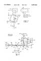
- FIG. 2shows, in pictorial form, a typical fundus camera 4000.
- ocular lens 100generates an intermediate image of fundus 1010 of a patient's eye 1000.
- the intermediate fundus image generated by ocular lens 100is located in the back focal plane of ocular lens 100.
- Relay lens 110is a transfer lens which generates a further intermediate image of fundus 1010.
- the intermediate fundus image generated by relay lens 110is imaged to CCD target 140 of a video port of fundus camera 4000 by internal focusing lens 120 and tube lens 130. Illumination of fundus 1010 is provided by light source 150.
- Output beam 185 from light source 150is focused as beam 180 onto geometrical beamsplitter 170 which is placed behind ocular lens 100 at an image of eye pupil 1020 of eye 1000.
- a geometrical beamsplitteris a mirror, with an aperture, for reflecting a portion of a beam and for transmitting a portion of a beam and, as shown in FIG. 2, geometrical beamsplitter 170 reflects illumination beam 180 and transmits the observation beam.
- output beam 185 from source 150is focused onto geometrical beamsplitter 170 in such a manner that ocular lens 100 focuses the reflection of beam 180 on eye pupil 1020 of eye 1000 in an "off-center" configuration.
- the path of output beam 185 from source 150 and the path of the observation beam which reaches CCD 140are separated in the anterior chamber of eye 1000. As a result, almost no light from output beam 185 is scattered back into the observation path of fundus camera 4000.
- ocular lens 100, relay lens 110, and tube lens 130are fixed and internal focusing lens 120 is movable.
- fundus camera 4000is physically moved into position so that output beam 185 from light source 150 is focused on eye pupil 1020.
- internal focusing lens 120is used to focus fundus 1010 on CCD 140.
- geometrical beamsplitter 170constitutes the aperture stop of the observation path and it is located at the focal plane of relay lens 110 so that the aperture is imaged to infinity (telecentricity).
- internal focusing lens 120images pupil 1020 into tube lens 130, and tube lens 130 ensures that the magnification of the whole system does not change when internal focusing lens 120 is moved to focus the image of fundus 1010 on CCD 140.
- Further beamsplittersare typically positioned between tube lens 130 and internal focusing lens 120 for use as an additional observational port.
- FIG. 3shows, in pictorial form, an embodiment of the present invention for use in connection with fundus camera 4000 shown in FIG. 2. Since ocular lens 100 is fixed, it is necessary to focus sample beam 200 separately. As shown in FIG. 3, sample beam 200 impinges upon beam scanner 210.
- Beam scanner 210may be fabricated, for example, as a galvanometric beam scanner such as the one that is disclosed in the thesis discussed in the Background of the Invention.
- the hatched lines in FIG. 3show the manner in which beam scanner 210 moves sample beam 200 and the manner in which sample beam 200 is imaged into eye pupil 1020.
- the chief rays of sample beam 200, at various scan positions of beam scanner 210describe a ray pencil which emerges from the center of beam scanner 210.
- the chief raysdescribe a ray pencil which emerges from a point of final deflection of beam scanner 210 since beam scanner 210 may be comprised of several deflectors and/or mirrors.
- the point of final deflection of beam scanner 210is disposed substantially in the back focal plane of scanner lens 215 which is mounted on movable stage 213 and
- beam scanner 210is rigidly connected to the movable stage of scanner lens 215 to ensure that the point of final deflection of beam scanner 210 is disposed substantially in the back focal plane of scanner lens 215 for substantially all focusing positions of scanner lens 215.
- the ray pencilis collimated by scanner lens 215.
- the collimated light impinges upon beamsplitter 220 and beamsplitter 220directs it to ocular lens 100.
- Ocular lens 100is positioned so that collimated light impinging thereon is focused into eye pupil 1020.
- the sample beamis focused by the optics of eye 1000 onto fundus 1010.
- the point of final deflection of beam scanner 210is imaged into eye pupil 1020 for all focusing positions because of the collimated space between ocular lens 100 and scanner lens 215. If this were not the case, then vignetting would occur whereby scanning of sample beam 200 would be limited by eye pupil 1020.
- the point of final deflection of beam scanner 210(which is imaged to the focal point of ocular lens 100 into eye pupil 1020) is not exactly focused into the same plane as the intermediate image of illumination source 150 which is located a finite distance from ocular lens 100 in the plane of geometrical beamsplitter 170. However, this is not critical because the distance between ocular lens 100 and geometrical beamsplitter 170 can be long compared to the focal length of ocular lens 100 so that the image of illumination source 150 is also almost in the same plane as the point of final deflection of beam scanner 210.
- point of final deflectionis not restricted to a single point but also encompasses an area in which the chief rays of the sample beam are finally deflected in the beam scanner.
- FIG. 4shows, in pictorial form, a portion of the beamsplitter apparatus utilized in fabricating an embodiment of the present invention.
- Introduction of beamsplitter 220 into fundus camera 4000causes a parallel shift of the optical axis of fundus camera 4000.
- the illumination opticsis designed so that the vertex of ocular lens 100 is not illuminated. This is done to avoid reflections from ocular lens 100 back into the observation path.
- the illumination coneis shifted and light beams may hit the vertex of ocular lens 100 and, thereby, cause false light to be reflected into the observation path. As shown in FIG. 4, this is avoided by the use of compensation plate 230.
- compensation plate 230The thickness and tilt angle of compensation plate 230 are determined in accordance with methods which are well known to those skilled in the art to compensate for the shift of the optical axis introduced by beamsplitter 220. Also, compensation plate 230 eliminates coma caused by tilted beamsplitter plate 220.
- FIG. 5shows, in pictorial form, a preferred embodiment of the present invention for use in connection with fundus camera 4000 shown in FIG. 2.
- OCT sample beam 200is coupled into fundus camera 4000 behind internal focusing lens 120.
- sample beam 200impinges upon beam scanner 210 which reflects sample beam 200 onto beamsplitter 290.
- Beamsplitter 290reflects the sample beam to internal focusing lens 120.
- the chief rays of sample beam 200, at various scan positions of beam scanner 210,describe a ray pencil which emerges from the center of beam scanner 210.
- the chief raysdescribe a ray pencil which emerges from a point of final deflection of beam scanner 210 since beam scanner 210 may be comprised of several deflectors and/or mirrors.
- the point of final deflection of beam scanner 210is disposed substantially in the back focal plane of internal focusing lens 120 and (b) mounting 281 for beamsplitter 290 and mounting 287 for beam scanner 210 are rigidly connected to internal focusing lens 120 so that they all move together. This ensures that the point of final deflection of beam scanner 210 is disposed substantially in the back focal plane of internal focusing lens 120 for substantially all focusing positions of internal focusing lens 120.
- the ray pencilis collimated by internal focusing lens 120 and is focused by relay lens 110 into the plane of geometrical beamsplitter 170. Then, ocular lens 100 focuses the ray pencil into eye pupil 1020.
- collimated sample beam 200is focused by internal focusing lens 120 in intermediate image plane 111 which is conjugate with CCD target 140.
- Relay lens 110images intermediate image plane 111 into intermediate image plane 113 which is equal to the back focal plane of ocular lens 100 in the case of an emetropic eye. Then, ocular lens 100 and the optics of eye 1000 focus the sample beam onto fundus 1010.
- mounting 281 for beamsplitter 290 and mounting 287 for beam scanner 210are rigidly connected to internal focusing lens 120 so that they all move together, the point of final deflection of beam scanner 210 is always imaged into the plane of geometrical beamsplitter 170, independent of the position of internal focusing lens 120. Hence, the scanning sample beam is not vignetted by the aperture stop of geometrical beamsplitter 170.
- the preferred embodiment shown in FIG. 5 and described aboveis advantageous because: (a) the use of scanner lens 215 of FIG. 3 is avoided and (b) the sample beam and the observation path are focused together.
- FIG. 5Ashows, in pictorial form, the embodiment of FIG. 5 which further includes crossed polarizers 181 and 182 and fixation targets 191 and 291.
- crossed polarizers 181 and 182are utilized, one polarizer 181 in the illumination path and polarizer 182 in the observation path of the fundus camera.
- Polarizer 181 in the illumination pathproduces substantially linearly polarized light
- crossed polarizer 182 in the observation patheliminates light from the illumination path which is reflected by the cornea, or by ocular lens 100.
- the fundusprimarily scatters and, therefore, primarily produces non-polarized light.
- presence of the crossed polarizer 182 in the observation pathincreases the signal reflected from the fundus when compared with light from the illumination path which is reflected by the cornea or by ocular lens 100.
- This aspect of the present inventionis superior to a prior art practice of tilting ocular lens 100 to reduce reflections therefrom from entering the observation path.
- the superiority of the present inventionresults from the fact that tilting of ocular lens 100 produces vignetting of the sample beam.
- reflection from ocular lens 100is removed by placing physical stop 161 in beam 185, between lens 160 and light source 150. Physical stop 161 is imaged onto ocular lens 100 to produce a hollow cone of illumination. As a result, ocular lens 100 is not illuminated at the center.
- a yet still further aspect of the present inventionaddresses a problem which is caused by the fact that the field of view of the viewing system of fundus camera 4000 is limited. As a result of this, a patient's eye must be rotated to move a field of interest into the center of the field of view of the fundus camera. This is done, in accordance with the prior art, by shining an external fixation light into the patient's other eye, i.e., the eye which is not being examined.
- an internal fixation targetis used to guide the patient's eye so that the new field of interest becomes centered and can be scanned by the OCT sample beam.
- the internal fixation targetis developed by placing an object such as, for example, needle 191, into the intermediate image of the fundus.
- a visible light sourcesuch as, for example, a visible LED is located in the image plane of a video port of the fundus camera.
- light 291 sourceis fixed to plate 293 which is manually movable in the x- and y-directions in a mount located at an image plane conjugate to CCD target 140.
- light source 291is coupled into the camera between tube lens 130 and internal focusing lens 120 by, for example, beamsplitter 297.
- image acquisition timeIn order to provide successful OCDR, image acquisition time must be very short because of saccadic movements of the eye.
- the image acquisition speed of apparatus described in the artis limited by the maximum speed of a translation stage of a reference mirror and by the amplitude of displacement of the reference mirror.
- the amplitudeIn accordance with OCDR, the amplitude must be in the range of the thickness of the sample, for example, the retina.
- the translation stage in the artis driven with a sawtooth-like voltage. However, for high frequencies, the response of the mechanical system becomes more or less sinusoidal because high frequency components of the sawtooth function are not transmitted by the damped mechanical system.
- FIG. 6shows, in pictorial form, a preferred embodiment of OCDR which is utilized in OCT.
- beam 500which is emitted by source 401, for example, a superluminescent diode, is split by beamsplitter 402 into reference beam 510 and sample beam 520.
- Reference beam 510(a) passes through rotating glass plate 403; (b) hits retroreflecting prism 404 and is reflected back, with a vertical offset; and (c) passes through glass plate 403 again.
- Glass plate 403has four facets of equal length and introduces a periodic change in the optical path in a manner which will be described below.
- Sample beam 520is reflected at mirror 415 and passes through glass plate 403 at a 45 degree angle with respect to reference beam 510.
- the sample beamstrikes retroreflecting prism 406 and is reflected back in a deeper plane through glass plate 403 so that it passes underneath mirror 415 and strikes mirror 417.
- Glass plate 403introduces a periodic change in the optical path which has the same period as that of reference beam 510, but with an offset of 45 degrees.
- the resulting path length difference between reference beam 510 and sample beam 520is linear.
- glass plate 403is symmetric, and the angle between reference beam 510 and sample beam 520 is substantially equal to 45 degrees, one obtains a symmetrical, sawtooth-like path variation and, therefore, a constant Doppler frequency.
- the Doppler frequency f2v/c, where c is the velocity of light and v is the "pathlength difference velocity" which will be described below.
- cthe velocity of light
- vthe "pathlength difference velocity" which will be described below.
- glass plate 403is a symmetrical four facet polygon provides that a sawtooth-like path length variation can be achieved.
- the angle between reference beam 510 and sample beam 520is substantially equal to 45 degrees provides that the sawtooth is symmetrical.
- sample beam 520is deflected by mirror 417 into sample beam 200 which was utilized as described above in conjunction with FIGS. 3 and 5.
- FIG. 8shows, in pictorial form, an embodiment of the present invention formed from the combination of apparatus shown in FIGS. 5 and 6.
- the sample beammay be injected into an optical fiber. Reflections from fundus 1010 are deflected by beamsplitter 409 and mirror 410 to beamsplitter 411. The reflected sample beam is then superimposed with reference beam 510 which is reflected by mirror 412 (mirror 412 is located underneath beam 500 which emerges from source 401).
- detectors 413 and 414measure periodic interference signals as a function of time and with frequencies equal to the Doppler frequency in a manner which has been described in the prior art.
- the phase difference of the two signalsis 180 degrees, which difference is compensated for in a manner which is well known in the art so that the two signals can be added to increase the signal to noise ratio.
- the apparatus shown in FIG. 6 and described aboveis utilized in an OCT fundus imaging apparatus, it is within the spirit of the present invention that the apparatus can be utilized in a ranging device for an autofocus system having a high capture range, a distance sensor for measurement of surface topography with micron resolution, and so forth.
- FIG. 7shows, in pictorial form, glass plate 403 and various views of retroreflecting prism 404.
- Glass plate 403rotates, and the rotation angle ⁇ is defined to be zero when glass surface I is perpendicular to incoming beam 510.
- incoming beam 510is refracted at glass surface I with an angle ⁇ ' which is related to the rotational angle ⁇ of glass plate 403 by Snell's law:
- nis the index of refraction of glass plate 403.
- Beam 510passes through glass plate 403 and is refracted again at surface II.
- the outgoing beamis parallel to the incoming beam.
- the outgoing beamhits retroreflecting prism 404 which is disposed perpendicular to the outgoing beam.
- the outgoing beamis reflected back towards glass plate 403 in a plane which is deeper than the plane of the incoming beam by an offset s, as shown in a side view of retroreflecting prism 404 in FIG. 7.
- the beampasses through glass plate once more, but deeper.
- the length of this optical pathhas to be compared with the optical pathlength that beam 510 experiences when it passes through glass plate 403 in a non-tilted position.
- the optical pathlength differenceis a nonlinear function of ⁇ .
- sample beam 520passes through glass plate 403 at a 45 degree angle relative to reference beam 510.
- the pathlength variation of sample beam 520 due to rotating glass plate 403is the same as has been set forth above for reference beam 510, but with an offset of ⁇ /4.
- the resulting pathlength variation for reference beam 510 and sample beam 520is substantially linear and, because of the symmetry of glass plate 403 and the fact that the angle between reference beams 510 and sample beam 520 is substantially equal to 45 degrees, one obtains a symmetrical saw tooth like path variation.
- the pathlength difference velocityis equal to the product of the rate of change of W( ⁇ )-W( ⁇ -/4) with ⁇ multiplied by the angular velocity of glass plate 403.
- beamsplitters 220 and 290are dichroic beamsplitters which are known in the art for reflecting wavelengths in the range of the sample beam and for transmitting other wavelengths.
- beamsplitters 220 and 290could be replaced by a minus filter which is known in the art which reflects only wavelengths in the range of the sample beam and transmits other wavelengths.
Landscapes
- Health & Medical Sciences (AREA)
- Physics & Mathematics (AREA)
- Life Sciences & Earth Sciences (AREA)
- General Physics & Mathematics (AREA)
- Nuclear Medicine, Radiotherapy & Molecular Imaging (AREA)
- Radiology & Medical Imaging (AREA)
- General Health & Medical Sciences (AREA)
- Medical Informatics (AREA)
- Biomedical Technology (AREA)
- Heart & Thoracic Surgery (AREA)
- Engineering & Computer Science (AREA)
- Molecular Biology (AREA)
- Surgery (AREA)
- Animal Behavior & Ethology (AREA)
- Ophthalmology & Optometry (AREA)
- Public Health (AREA)
- Veterinary Medicine (AREA)
- Biophysics (AREA)
- Eye Examination Apparatus (AREA)
- Investigating Or Analysing Materials By Optical Means (AREA)
Abstract
Description
L=c/B
sin φ'=sin (φ)/n
W(φ)=D(n-1)-nD/cosφ'+D cos (φ-φ')/cosφ'
Claims (17)
Priority Applications (5)
| Application Number | Priority Date | Filing Date | Title |
|---|---|---|---|
| US08/169,705US5537162A (en) | 1993-12-17 | 1993-12-17 | Method and apparatus for optical coherence tomographic fundus imaging without vignetting |
| DE69432395TDE69432395T2 (en) | 1993-12-17 | 1994-11-11 | Method and device for tomographic imaging of the fundus by means of optical coherence |
| EP94117822AEP0659383B1 (en) | 1993-12-17 | 1994-11-11 | Method and apparatus for optical coherence tomographic fundus imaging |
| ES94117822TES2194018T3 (en) | 1993-12-17 | 1994-11-11 | METHOD AND APPARATUS FOR THE GENERATION OF EYE FUND IMAGES BY OPTICAL COHERENCE TOMOGRAPHY. |
| JP31097994AJP3725572B2 (en) | 1993-12-17 | 1994-12-14 | Apparatus for illuminating the fundus using a scanning sample radiation beam |
Applications Claiming Priority (1)
| Application Number | Priority Date | Filing Date | Title |
|---|---|---|---|
| US08/169,705US5537162A (en) | 1993-12-17 | 1993-12-17 | Method and apparatus for optical coherence tomographic fundus imaging without vignetting |
Publications (1)
| Publication Number | Publication Date |
|---|---|
| US5537162Atrue US5537162A (en) | 1996-07-16 |
Family
ID=22616833
Family Applications (1)
| Application Number | Title | Priority Date | Filing Date |
|---|---|---|---|
| US08/169,705Expired - LifetimeUS5537162A (en) | 1993-12-17 | 1993-12-17 | Method and apparatus for optical coherence tomographic fundus imaging without vignetting |
Country Status (5)
| Country | Link |
|---|---|
| US (1) | US5537162A (en) |
| EP (1) | EP0659383B1 (en) |
| JP (1) | JP3725572B2 (en) |
| DE (1) | DE69432395T2 (en) |
| ES (1) | ES2194018T3 (en) |
Cited By (83)
| Publication number | Priority date | Publication date | Assignee | Title |
|---|---|---|---|---|
| WO1997030627A1 (en)* | 1996-02-23 | 1997-08-28 | Talia Technology Ltd. | A three dimensional imaging apparatus and a method for use thereof |
| WO1997037584A1 (en)* | 1996-04-09 | 1997-10-16 | Lee Heacock Gregory | Wide field of view scanning laser ophthalmoscope |
| US5719659A (en)* | 1996-07-30 | 1998-02-17 | Kowa Company Ltd. | Ophthalmic apparatus having light polarizing means |
| WO1999027843A1 (en)* | 1997-11-28 | 1999-06-10 | The Lions Eye Institute Of Western Australia Incorporated | Stereo scanning laser ophthalmoscope |
| US5921926A (en)* | 1997-07-28 | 1999-07-13 | University Of Central Florida | Three dimensional optical imaging colposcopy |
| EP0941692A1 (en) | 1998-03-09 | 1999-09-15 | Herbert Schwind GmbH & Co. KG | Method and device for examining the eye |
| DE19812297A1 (en)* | 1998-03-09 | 1999-09-23 | Schwind Gmbh & Co Kg Herbert | Method and device for examining an eye section |
| US5975697A (en)* | 1998-11-25 | 1999-11-02 | Oti Ophthalmic Technologies, Inc. | Optical mapping apparatus with adjustable depth resolution |
| WO2000028885A1 (en)* | 1998-11-18 | 2000-05-25 | The Lions Eye Institute Of Western Australia Incorporated | Limited coherence stereo ophthalmoscope |
| US6144456A (en)* | 1995-05-04 | 2000-11-07 | Haag-Streit Ag | Apparatus having a multiple angle transparent rotating element for measuring the thickness of transparent objects |
| US6419360B1 (en) | 2000-07-01 | 2002-07-16 | Carl-Zeiss-Stiftung | Scanner |
| AU755231B2 (en)* | 1998-11-18 | 2002-12-05 | Lions Eye Institute Limited | Limited coherence stereo ophthalmoscope |
| US20030045798A1 (en)* | 2001-09-04 | 2003-03-06 | Richard Hular | Multisensor probe for tissue identification |
| US6546272B1 (en) | 1999-06-24 | 2003-04-08 | Mackinnon Nicholas B. | Apparatus for in vivo imaging of the respiratory tract and other internal organs |
| US6561648B2 (en) | 2001-05-23 | 2003-05-13 | David E. Thomas | System and method for reconstruction of aberrated wavefronts |
| US20030199769A1 (en)* | 2002-04-08 | 2003-10-23 | Adrian Podoleanu | Apparatus for high resolution imaging of moving organs |
| WO2003039332A3 (en)* | 2001-10-16 | 2003-12-04 | Schepens Eye Res Inst | Device for digital retinal imaging |
| US6769769B2 (en) | 2002-06-28 | 2004-08-03 | Oti Ophthalmic Technologies Inc. | Optical mapping apparatus with adjustable depth resolution and multiple functionality |
| US20040181168A1 (en)* | 2003-03-13 | 2004-09-16 | Plant Charles P. | Saccadic motion sensing |
| US20050089208A1 (en)* | 2003-07-22 | 2005-04-28 | Rui-Tao Dong | System and method for generating digital images of a microscope slide |
| US20050113678A1 (en)* | 2002-01-15 | 2005-05-26 | Villard Joseph W. | Methods and compositions to reduce scattering of light during therapeutic and diagnostic imaging procedures |
| US20050174578A1 (en)* | 2004-02-10 | 2005-08-11 | Jay Wei | High efficiency low coherence interferometry |
| US20050203422A1 (en)* | 2004-02-10 | 2005-09-15 | Jay Wei | Optical apparatus and methods for performing eye examinations |
| US20050200849A1 (en)* | 1999-02-01 | 2005-09-15 | Boston Scientific Scimed, Inc. | Medical scanning system and related method of scanning |
| US20060058682A1 (en)* | 2002-06-12 | 2006-03-16 | Miller Donald T | Method and apparatus for improving both lateral and axial resolution in ophthalmoscopy |
| US20060114411A1 (en)* | 2004-11-08 | 2006-06-01 | Jay Wei | Optical apparatus and method for comprehensive eye diagnosis |
| US20060290885A1 (en)* | 2005-06-28 | 2006-12-28 | Eastman Kodak Company | Health care kiosk having automated diagnostic eye examination and a fulfillment remedy based thereon |
| US20070046948A1 (en)* | 2005-08-26 | 2007-03-01 | University Of Kent | Optical mapping apparatus |
| US20070127033A1 (en)* | 2005-11-30 | 2007-06-07 | Nidek Co., Ltd. | Apparatus using optical coherence tomography based on spectral interference, and an ophthalmic apparatus |
| EP1806092A1 (en)* | 2006-01-10 | 2007-07-11 | Kabushiki Kaisha TOPCON | A fundus observation device |
| US20070159597A1 (en)* | 2006-01-11 | 2007-07-12 | Yasufumi Fukuma | Optical Image-Measuring Device |
| US20070188707A1 (en)* | 2006-02-06 | 2007-08-16 | Nidek Co., Ltd. | Retinal function measurement apparatus |
| EP1836953A1 (en)* | 2006-03-24 | 2007-09-26 | Kabushiki Kaisha TOPCON | A fundus observation device |
| EP1894518A1 (en)* | 2006-08-29 | 2008-03-05 | Kabushiki Kaisha TOPCON | Eye movement measuring apparatus, eye movement measuring method and recording medium |
| US20080309876A1 (en)* | 2007-06-15 | 2008-12-18 | Massie Norbert A | Method And Apparatus For Imaging An Eye Of A Small Animal |
| US20090115964A1 (en)* | 2005-10-31 | 2009-05-07 | Nidek Co., Ltd. | Ophthalmic Photographing Apparatus |
| US20090128775A1 (en)* | 2006-06-12 | 2009-05-21 | Opto Eletronica S/A | System for obtaining a fundus image |
| US20090141237A1 (en)* | 2007-11-02 | 2009-06-04 | Bioptigen, Inc. | Integrated Optical Coherence Imaging Systems for Use in Ophthalmic Applications and Related Methods and Computer Program Products |
| US20090190092A1 (en)* | 2007-03-23 | 2009-07-30 | Kabushi Kaisha Topcon | Fundus oculi observation device and ophthalmic image display device |
| US20100103374A1 (en)* | 2008-10-24 | 2010-04-29 | Canon Kabushiki Kaisha | Connection adapter, optical tomographic imaging apparatus, program for executing imaging method and memory device for the program |
| US20100128221A1 (en)* | 2006-05-31 | 2010-05-27 | Indiana University Research And Technology Corporation | Laser scanning digital camera with pupil periphery illumination and potential for multiply scattered light imaging |
| CN101566727B (en)* | 2008-04-22 | 2010-12-22 | 深圳市莫廷影像技术有限公司 | Ophthalmonogy probe imaging system |
| US20110282331A1 (en)* | 2010-05-13 | 2011-11-17 | Oprobe, Llc | Optical coherence tomography with multiple imaging instruments |
| CN100998495B (en)* | 2006-01-10 | 2012-01-25 | 株式会社拓普康 | Fundus observation device |
| DE19832175B4 (en)* | 1997-07-21 | 2012-02-09 | Carl Zeiss Meditec Ag | Methods and arrangements for transversal optical coherence tomography |
| US8427654B2 (en) | 2006-06-20 | 2013-04-23 | Carl Zeiss Meditec, Inc. | Spectral domain optical coherence tomography system |
| EP2620095A1 (en) | 2012-01-26 | 2013-07-31 | Canon Kabushiki Kaisha | Optical coherence tomographic apparatus |
| DE102012022058A1 (en) | 2012-11-08 | 2014-05-08 | Carl Zeiss Meditec Ag | Flexible, multimodal retina image acquisition and measurement system |
| DE102012022861A1 (en) | 2012-11-19 | 2014-05-22 | Carl Zeiss Meditec Ag | Device for compensating reflections in fundus image of fundus cameras for investigating eye fundus, has optical illuminating- and imaging system with beam-forming and beam-imaging optical elements, and unit for receiving light |
| WO2015027189A3 (en)* | 2013-08-22 | 2015-06-04 | The Cleveland Clinic Foundation | Microscope-integrated oct system with an electrically tunable focus |
| US9239454B2 (en) | 2009-09-24 | 2016-01-19 | Carl Zeiss Microscopy Gmbh | Microscope having light sheet illumination of a sample region |
| US9241626B2 (en) | 2013-03-14 | 2016-01-26 | Carl Zeiss Meditec, Inc. | Systems and methods for improved acquisition of ophthalmic optical coherence tomography data |
| US9289117B2 (en) | 2013-04-30 | 2016-03-22 | Canon Kabushiki Kaisha | Optical tomographic imaging apparatus |
| US9427150B2 (en) | 2013-04-30 | 2016-08-30 | Canon Kabushiki Kaisha | Optical tomographic imaging apparatus |
| US9427149B2 (en) | 2013-04-30 | 2016-08-30 | Canon Kabushiki Kaisha | Optical tomographic imaging apparatus |
| US9427147B2 (en) | 2012-02-17 | 2016-08-30 | The Regents Of The University Of California | Directional optical coherence tomography systems and methods |
| US9486137B2 (en)* | 2013-03-15 | 2016-11-08 | Amo Wavefront Sciences, Llc | Angular multiplexed optical coherence tomography systems and methods |
| US20160338589A1 (en)* | 2014-01-30 | 2016-11-24 | Oscar M. Carrasco-Zevallos | Systems and methods for eye tracking for motion corrected ophthalmic optical coherenece tomography |
| US20170000342A1 (en) | 2015-03-16 | 2017-01-05 | Magic Leap, Inc. | Methods and systems for detecting health conditions by imaging portions of the eye, including the fundus |
| US9655517B2 (en) | 2012-02-02 | 2017-05-23 | Visunex Medical Systems Co. Ltd. | Portable eye imaging apparatus |
| US20170343786A1 (en)* | 2014-12-22 | 2017-11-30 | Ge Healthcare Bio-Sciences Ab | Improvements In and Relating to LED Illumination in Microscopy |
| US9848773B2 (en) | 2015-01-26 | 2017-12-26 | Visunex Medical Systems Co. Ltd. | Disposable cap for an eye imaging apparatus and related methods |
| US9907467B2 (en) | 2012-03-17 | 2018-03-06 | Visunex Medical Systems Co. Ltd. | Eye imaging apparatus with a wide field of view and related methods |
| US9986908B2 (en) | 2014-06-23 | 2018-06-05 | Visunex Medical Systems Co. Ltd. | Mechanical features of an eye imaging apparatus |
| US9993153B2 (en)* | 2016-07-06 | 2018-06-12 | Santec Corporation | Optical coherence tomography system and method with multiple apertures |
| US10016178B2 (en) | 2012-02-02 | 2018-07-10 | Visunex Medical Systems Co. Ltd. | Eye imaging apparatus and systems |
| US20180310860A1 (en)* | 2015-10-19 | 2018-11-01 | Sony Corporation | Distance measurement device and imaging system |
| US10206567B2 (en) | 2017-07-12 | 2019-02-19 | Santec Corporation | Dual wavelength resampling system and method |
| US10408600B2 (en) | 2017-06-22 | 2019-09-10 | Santec Corporation | Optical coherence tomography with a fizeau-type interferometer |
| US10426336B2 (en) | 2015-06-01 | 2019-10-01 | Santec Corporation | Optical coherence tomography system combining two wavelengths |
| US10426337B2 (en) | 2017-06-01 | 2019-10-01 | Santec Corporation | Flow imaging in an optical coherence tomography (OCT) system |
| US10459231B2 (en) | 2016-04-08 | 2019-10-29 | Magic Leap, Inc. | Augmented reality systems and methods with variable focus lens elements |
| US10502546B2 (en) | 2017-11-07 | 2019-12-10 | Santec Corporation | Systems and methods for variable-range fourier domain imaging |
| US10548520B2 (en) | 2015-04-01 | 2020-02-04 | Santec Corporation | Non-invasive optical measurement of blood analyte |
| US10677580B2 (en) | 2016-04-27 | 2020-06-09 | Santec Corporation | Optical coherence tomography system using polarization switching |
| US10838047B2 (en) | 2018-04-17 | 2020-11-17 | Santec Corporation | Systems and methods for LIDAR scanning of an environment over a sweep of wavelengths |
| US10869623B2 (en) | 2014-05-28 | 2020-12-22 | Santec Corporation | Non-invasive optical measurement of blood analyte |
| US10962855B2 (en) | 2017-02-23 | 2021-03-30 | Magic Leap, Inc. | Display system with variable power reflector |
| US11067671B2 (en) | 2018-04-17 | 2021-07-20 | Santec Corporation | LIDAR sensing arrangements |
| US11213200B2 (en) | 2018-03-22 | 2022-01-04 | Santec Corporation | Topographical imaging using combined sensing inputs |
| US20220257111A1 (en)* | 2019-08-01 | 2022-08-18 | Carl Zeiss Meditec, Inc. | Ophthalmic imaging with k-mirror scanning, efficient interferometry, and pupil alignment through spatial frequency analysis |
| US11885706B2 (en) | 2017-12-28 | 2024-01-30 | Transitions Optical, Ltd. | Method and system for measuring optical characteristics of a contact lens |
| US12313883B2 (en) | 2023-03-03 | 2025-05-27 | santec Holdings Corporation | Photonic beam steering device with wavelength sweep |
Families Citing this family (17)
| Publication number | Priority date | Publication date | Assignee | Title |
|---|---|---|---|---|
| US5673097A (en)* | 1996-04-15 | 1997-09-30 | Odyssey Optical Systems Llc | Portable scanning laser ophthalmoscope |
| JP4138027B2 (en)* | 1997-06-02 | 2008-08-20 | イザット,ジョーゼフ,エイ. | Imaging Doppler flow using optical coherence tomography |
| FR2791548B1 (en)* | 1999-04-01 | 2001-07-06 | Univ Paris Vii Denis Diderot | DEVICE FOR OBSERVING A HIGH RESOLUTION BODY |
| JP2002065611A (en)* | 2000-08-28 | 2002-03-05 | Kowa Co | Fundus camera |
| DE10042751A1 (en)* | 2000-08-31 | 2002-03-14 | Thomas Hellmuth | System for the contactless measurement of the optical image quality of an eye |
| DE10360570B4 (en)* | 2003-12-22 | 2006-01-12 | Carl Zeiss | Optical measuring system and optical measuring method |
| JP4916779B2 (en)* | 2005-09-29 | 2012-04-18 | 株式会社トプコン | Fundus observation device |
| JP4850495B2 (en)* | 2005-10-12 | 2012-01-11 | 株式会社トプコン | Fundus observation apparatus and fundus observation program |
| EP1785690A1 (en)* | 2005-11-10 | 2007-05-16 | Haag-Streit Ag | Method and device for determining an object s geometric characteristics |
| JP2007181632A (en)* | 2006-01-10 | 2007-07-19 | Topcon Corp | Fundus observation device |
| JP4884777B2 (en)* | 2006-01-11 | 2012-02-29 | 株式会社トプコン | Fundus observation device |
| JP4855150B2 (en)* | 2006-06-09 | 2012-01-18 | 株式会社トプコン | Fundus observation apparatus, ophthalmic image processing apparatus, and ophthalmic image processing program |
| JP4969925B2 (en)* | 2006-06-28 | 2012-07-04 | 株式会社トプコン | Fundus observation device |
| EP2090223A1 (en)* | 2008-02-15 | 2009-08-19 | OPTOPOL Technology Spolka Akcyjna | Optical set for examining of objects and method for examining of objects using optical devices |
| DE102008011836A1 (en)* | 2008-02-28 | 2009-09-03 | Carl Zeiss Meditec Ag | Ophthalmological device and method for observation, examination, diagnosis and / or therapy of an eye |
| JP2015039580A (en)* | 2013-08-23 | 2015-03-02 | キヤノン株式会社 | Optical tomographic imaging device |
| JP7164328B2 (en)* | 2018-06-14 | 2022-11-01 | 株式会社トプコン | Ophthalmic device and control method for ophthalmic device |
Citations (3)
| Publication number | Priority date | Publication date | Assignee | Title |
|---|---|---|---|---|
| US4406542A (en)* | 1981-07-31 | 1983-09-27 | Spectra-Physics, Inc. | Rapid scanning autocorrelation detector |
| US4900144A (en)* | 1987-10-28 | 1990-02-13 | Kowa Company Ltd. | Three-dimensional shape measurement apparatus |
| DE3926652A1 (en)* | 1989-08-11 | 1991-04-18 | Rodenstock Instr | Ophthalmic equipment for angiographic examination of eye - has detector with confocal shutter of dia. corresp. to that of beam focussed on image |
Family Cites Families (5)
| Publication number | Priority date | Publication date | Assignee | Title |
|---|---|---|---|---|
| JPS62266032A (en)* | 1986-05-12 | 1987-11-18 | 興和株式会社 | Fundus examination device |
| US4883061A (en)* | 1988-02-29 | 1989-11-28 | The Board Of Trustees Of The University Of Illinois | Method and apparatus for measuring the thickness of eye components |
| US4933756A (en)* | 1988-04-12 | 1990-06-12 | Kabushiki Kaisha Topcon | Eye fundus camera |
| US5094523A (en)* | 1990-05-11 | 1992-03-10 | Eye Research Institute Of Retina Foundation | Bidirectional light steering apparatus |
| JP3479069B2 (en)* | 1991-04-29 | 2003-12-15 | マサチューセッツ・インステチュート・オブ・テクノロジー | Method and apparatus for optical imaging and measurement |
- 1993
- 1993-12-17USUS08/169,705patent/US5537162A/ennot_activeExpired - Lifetime
- 1994
- 1994-11-11ESES94117822Tpatent/ES2194018T3/ennot_activeExpired - Lifetime
- 1994-11-11EPEP94117822Apatent/EP0659383B1/ennot_activeExpired - Lifetime
- 1994-11-11DEDE69432395Tpatent/DE69432395T2/ennot_activeExpired - Lifetime
- 1994-12-14JPJP31097994Apatent/JP3725572B2/ennot_activeExpired - Fee Related
Patent Citations (3)
| Publication number | Priority date | Publication date | Assignee | Title |
|---|---|---|---|---|
| US4406542A (en)* | 1981-07-31 | 1983-09-27 | Spectra-Physics, Inc. | Rapid scanning autocorrelation detector |
| US4900144A (en)* | 1987-10-28 | 1990-02-13 | Kowa Company Ltd. | Three-dimensional shape measurement apparatus |
| DE3926652A1 (en)* | 1989-08-11 | 1991-04-18 | Rodenstock Instr | Ophthalmic equipment for angiographic examination of eye - has detector with confocal shutter of dia. corresp. to that of beam focussed on image |
Non-Patent Citations (10)
| Title |
|---|
| "Feurtosecond Optical Ranging in Biological Systems" by J. G. Fujimoto et al. Optics Letters, vol. 10, No. 3, Mar. 1986, pp. 150-152. |
| "New Measurement System for Fault Location in Optical Waveguide Devices Based on Interferometric Technique" by K. Takada et al. Applied Optics, vol. 26, No. 9, May 1, 1987, pp. 1603-1606. |
| "Optical Coherence Tomography" by Huang et al., Science, 254, Nov., 22, 1991, pp. 1178-1181. |
| Feurtosecond Optical Ranging in Biological Systems by J. G. Fujimoto et al. Optics Letters, vol. 10, No. 3, Mar. 1986, pp. 150 152.* |
| New Measurement System for Fault Location in Optical Waveguide Devices Based on Interferometric Technique by K. Takada et al. Applied Optics, vol. 26, No. 9, May 1, 1987, pp. 1603 1606.* |
| Optical Coherence Tomography by Huang et al., Science, 254, Nov., 22, 1991, pp. 1178 1181.* |
| Ph.D. thesis "Optical Coherence Tomography" David Huang, Massachusetts Institute of Technology, May, 1993. |
| Ph.D. thesis Optical Coherence Tomography David Huang, Massachusetts Institute of Technology, May, 1993.* |
| Section 7.5.8 of "Principles of Optics" 6th Edition, M. Born and E. Wolf, Pergamon Press, New York (1986) (No Month). |
| Section 7.5.8 of Principles of Optics 6th Edition, M. Born and E. Wolf, Pergamon Press, New York (1986) (No Month).* |
Cited By (195)
| Publication number | Priority date | Publication date | Assignee | Title |
|---|---|---|---|---|
| US6144456A (en)* | 1995-05-04 | 2000-11-07 | Haag-Streit Ag | Apparatus having a multiple angle transparent rotating element for measuring the thickness of transparent objects |
| WO1997030627A1 (en)* | 1996-02-23 | 1997-08-28 | Talia Technology Ltd. | A three dimensional imaging apparatus and a method for use thereof |
| WO1997037584A1 (en)* | 1996-04-09 | 1997-10-16 | Lee Heacock Gregory | Wide field of view scanning laser ophthalmoscope |
| US5784148A (en)* | 1996-04-09 | 1998-07-21 | Heacock; Gregory Lee | Wide field of view scanning laser ophthalmoscope |
| US5719659A (en)* | 1996-07-30 | 1998-02-17 | Kowa Company Ltd. | Ophthalmic apparatus having light polarizing means |
| DE19832175B4 (en)* | 1997-07-21 | 2012-02-09 | Carl Zeiss Meditec Ag | Methods and arrangements for transversal optical coherence tomography |
| US6072765A (en)* | 1997-07-28 | 2000-06-06 | University Of Central Florida | Optical disk readout method using optical coherence tomography and spectral interferometry |
| US6141577A (en)* | 1997-07-28 | 2000-10-31 | University Of Central Florida | Three dimensional optical imaging colposcopy |
| US5921926A (en)* | 1997-07-28 | 1999-07-13 | University Of Central Florida | Three dimensional optical imaging colposcopy |
| WO1999027843A1 (en)* | 1997-11-28 | 1999-06-10 | The Lions Eye Institute Of Western Australia Incorporated | Stereo scanning laser ophthalmoscope |
| GB2347816A (en)* | 1997-11-28 | 2000-09-13 | Lions Eye Inst Australia Inc | Stereo scanning laser ophthalmoscope |
| US6379006B1 (en) | 1997-11-28 | 2002-04-30 | The Lions Eye Institute Of Western Australia Incorporated | Stereo scanning laser ophthalmoscope |
| US6698887B2 (en) | 1997-11-28 | 2004-03-02 | The Lions Eye Institute Of Western Australia Incorporated | Stereo scanning laser ophthalmoscope |
| GB2347816B (en)* | 1997-11-28 | 2002-09-04 | Lions Eye Inst Australia Inc | Stereo scanning laser ophthalmoscope |
| DE19812297A1 (en)* | 1998-03-09 | 1999-09-23 | Schwind Gmbh & Co Kg Herbert | Method and device for examining an eye section |
| DE19812297C2 (en)* | 1998-03-09 | 2001-11-08 | Schwind Gmbh & Co Kg Herbert | Method and device for examining an eye section |
| EP0941692A1 (en) | 1998-03-09 | 1999-09-15 | Herbert Schwind GmbH & Co. KG | Method and device for examining the eye |
| US6095648A (en)* | 1998-03-09 | 2000-08-01 | Herbert Schwind Gmbh & Co. Kg | Process and arrangement for examining a section of the eye |
| AU755231B2 (en)* | 1998-11-18 | 2002-12-05 | Lions Eye Institute Limited | Limited coherence stereo ophthalmoscope |
| WO2000028885A1 (en)* | 1998-11-18 | 2000-05-25 | The Lions Eye Institute Of Western Australia Incorporated | Limited coherence stereo ophthalmoscope |
| US5975697A (en)* | 1998-11-25 | 1999-11-02 | Oti Ophthalmic Technologies, Inc. | Optical mapping apparatus with adjustable depth resolution |
| US7797035B2 (en)* | 1999-02-01 | 2010-09-14 | Boston Scientific Scimed, Inc. | Medical scanning system and related method of scanning |
| US20050200849A1 (en)* | 1999-02-01 | 2005-09-15 | Boston Scientific Scimed, Inc. | Medical scanning system and related method of scanning |
| US20100305434A1 (en)* | 1999-02-01 | 2010-12-02 | Boston Scientific Scimed, Inc. | Medical scanning system and related method of scanning |
| US8099157B2 (en) | 1999-02-01 | 2012-01-17 | Boston Scientific Scimed, Inc. | Medical scanning system and related method of scanning |
| US6546272B1 (en) | 1999-06-24 | 2003-04-08 | Mackinnon Nicholas B. | Apparatus for in vivo imaging of the respiratory tract and other internal organs |
| US6419360B1 (en) | 2000-07-01 | 2002-07-16 | Carl-Zeiss-Stiftung | Scanner |
| US7077521B2 (en) | 2001-05-23 | 2006-07-18 | Thomas David E | System and method for reconstruction of aberrated wavefronts |
| US20040257529A1 (en)* | 2001-05-23 | 2004-12-23 | David Thomas | System and method for reconstruction of aberrated wavefronts |
| US20030223039A1 (en)* | 2001-05-23 | 2003-12-04 | David Thomas | System and method for reconstruction of aberrated wavefronts |
| US6561648B2 (en) | 2001-05-23 | 2003-05-13 | David E. Thomas | System and method for reconstruction of aberrated wavefronts |
| US20030045798A1 (en)* | 2001-09-04 | 2003-03-06 | Richard Hular | Multisensor probe for tissue identification |
| US20050261568A1 (en)* | 2001-09-04 | 2005-11-24 | Bioluminate, Inc. | Multisensor probe for tissue identification |
| WO2003039332A3 (en)* | 2001-10-16 | 2003-12-04 | Schepens Eye Res Inst | Device for digital retinal imaging |
| AU2002363421B2 (en)* | 2001-10-16 | 2008-10-16 | Aeon Imaging, LLC | Device for digital retinal imaging |
| US20100298716A1 (en)* | 2002-01-15 | 2010-11-25 | Board Of Regents, The University Of Texas System | Methods and compositions to reduce scattering of light during therapeutic and diagnostic imaging procedures |
| US20050113678A1 (en)* | 2002-01-15 | 2005-05-26 | Villard Joseph W. | Methods and compositions to reduce scattering of light during therapeutic and diagnostic imaging procedures |
| US7747315B2 (en) | 2002-01-15 | 2010-06-29 | Board Of Regents, The University Of Texas System | Methods and compositions to reduce scattering of light during therapeutic and diagnostic imaging procedures |
| US7983736B2 (en) | 2002-01-15 | 2011-07-19 | Board Of Regents, The University Of Texas System | Methods and compositions to reduce scattering of light during therapeutic and diagnostic imaging procedures |
| US7113818B2 (en) | 2002-04-08 | 2006-09-26 | Oti Ophthalmic Technologies Inc. | Apparatus for high resolution imaging of moving organs |
| US20030199769A1 (en)* | 2002-04-08 | 2003-10-23 | Adrian Podoleanu | Apparatus for high resolution imaging of moving organs |
| US20060058682A1 (en)* | 2002-06-12 | 2006-03-16 | Miller Donald T | Method and apparatus for improving both lateral and axial resolution in ophthalmoscopy |
| US7364296B2 (en) | 2002-06-12 | 2008-04-29 | University Of Rochester | Method and apparatus for improving both lateral and axial resolution in ophthalmoscopy |
| US6769769B2 (en) | 2002-06-28 | 2004-08-03 | Oti Ophthalmic Technologies Inc. | Optical mapping apparatus with adjustable depth resolution and multiple functionality |
| US7682024B2 (en)* | 2003-03-13 | 2010-03-23 | Plant Charles P | Saccadic motion sensing |
| US20040181168A1 (en)* | 2003-03-13 | 2004-09-16 | Plant Charles P. | Saccadic motion sensing |
| US20050089208A1 (en)* | 2003-07-22 | 2005-04-28 | Rui-Tao Dong | System and method for generating digital images of a microscope slide |
| WO2005010495A3 (en)* | 2003-07-22 | 2005-06-30 | Trestle Corp | System and method for generating digital images of a microscope slide |
| US7280221B2 (en) | 2004-02-10 | 2007-10-09 | Optovue, Inc. | High efficiency low coherence interferometry |
| US20050174578A1 (en)* | 2004-02-10 | 2005-08-11 | Jay Wei | High efficiency low coherence interferometry |
| US7631970B2 (en)* | 2004-02-10 | 2009-12-15 | Carl Zeiss Meditec, Inc. | Optical apparatus and methods for performing eye examinations |
| US20050203422A1 (en)* | 2004-02-10 | 2005-09-15 | Jay Wei | Optical apparatus and methods for performing eye examinations |
| US20100283972A1 (en)* | 2004-03-13 | 2010-11-11 | Plant Charles P | Saccadic Motion Detection System |
| US8162479B2 (en) | 2004-03-13 | 2012-04-24 | Humphries Kenneth C | Saccadic motion detection system |
| US20060114411A1 (en)* | 2004-11-08 | 2006-06-01 | Jay Wei | Optical apparatus and method for comprehensive eye diagnosis |
| WO2006052479A3 (en)* | 2004-11-08 | 2006-10-19 | Optovue Inc | Optical apparatus and method for comprehensive eye diagnosis |
| US7140730B2 (en) | 2004-11-08 | 2006-11-28 | Optovue, Inc. | Optical apparatus and method for comprehensive eye diagnosis |
| US7384146B2 (en) | 2005-06-28 | 2008-06-10 | Carestream Health, Inc. | Health care kiosk having automated diagnostic eye examination and a fulfillment remedy based thereon |
| US20060290885A1 (en)* | 2005-06-28 | 2006-12-28 | Eastman Kodak Company | Health care kiosk having automated diagnostic eye examination and a fulfillment remedy based thereon |
| US20070046948A1 (en)* | 2005-08-26 | 2007-03-01 | University Of Kent | Optical mapping apparatus |
| US7466423B2 (en) | 2005-08-26 | 2008-12-16 | University Of Kent | Optical mapping apparatus |
| US8899751B2 (en) | 2005-10-31 | 2014-12-02 | Nidek Co., Ltd | Ophthalmic photographing apparatus |
| US20090115964A1 (en)* | 2005-10-31 | 2009-05-07 | Nidek Co., Ltd. | Ophthalmic Photographing Apparatus |
| US20100315590A1 (en)* | 2005-10-31 | 2010-12-16 | Nidek Co., Ltd. | Ophthalmic photographing apparatus |
| US8556423B2 (en) | 2005-10-31 | 2013-10-15 | Nidek Co., Ltd. | Ophthalmic photographing apparatus |
| US8025402B2 (en) | 2005-10-31 | 2011-09-27 | Nidek Co., Ltd. | Ophthalmic photographing apparatus |
| US7557928B2 (en) | 2005-11-30 | 2009-07-07 | Nidek Co., Ltd. | Apparatus using optical coherence tomography based on spectral interference, and an ophthalmic apparatus |
| US20070127033A1 (en)* | 2005-11-30 | 2007-06-07 | Nidek Co., Ltd. | Apparatus using optical coherence tomography based on spectral interference, and an ophthalmic apparatus |
| US20070159595A1 (en)* | 2006-01-10 | 2007-07-12 | Yasufumi Fukuma | Fundus Observation Device |
| EP1806092A1 (en)* | 2006-01-10 | 2007-07-11 | Kabushiki Kaisha TOPCON | A fundus observation device |
| CN100998495B (en)* | 2006-01-10 | 2012-01-25 | 株式会社拓普康 | Fundus observation device |
| US7784941B2 (en) | 2006-01-10 | 2010-08-31 | Kabushiki Kaisha Topcon | Fundus observation device |
| US7837328B2 (en)* | 2006-01-11 | 2010-11-23 | Kabushiki Kaisha Topcon | Optical image-measuring device |
| US20070159597A1 (en)* | 2006-01-11 | 2007-07-12 | Yasufumi Fukuma | Optical Image-Measuring Device |
| US7506978B2 (en) | 2006-02-06 | 2009-03-24 | Nidek Co., Ltd. | Retinal function measurement apparatus |
| USRE44226E1 (en) | 2006-02-06 | 2013-05-21 | Nidek Co., Ltd. | Retinal function measurement apparatus |
| USRE45344E1 (en) | 2006-02-06 | 2015-01-20 | Nidek Co., Ltd. | Retinal function measurement apparatus |
| US20070188707A1 (en)* | 2006-02-06 | 2007-08-16 | Nidek Co., Ltd. | Retinal function measurement apparatus |
| CN101040776B (en)* | 2006-03-24 | 2010-09-29 | 株式会社拓普康 | fundus observation device |
| US7549746B2 (en) | 2006-03-24 | 2009-06-23 | Kabushiki Kaisha Topcon | Fundus observation device |
| US20070222945A1 (en)* | 2006-03-24 | 2007-09-27 | Hisashi Tsukada | Fundus Observation Device |
| EP1836953A1 (en)* | 2006-03-24 | 2007-09-26 | Kabushiki Kaisha TOPCON | A fundus observation device |
| US8488895B2 (en) | 2006-05-31 | 2013-07-16 | Indiana University Research And Technology Corp. | Laser scanning digital camera with pupil periphery illumination and potential for multiply scattered light imaging |
| US20100128221A1 (en)* | 2006-05-31 | 2010-05-27 | Indiana University Research And Technology Corporation | Laser scanning digital camera with pupil periphery illumination and potential for multiply scattered light imaging |
| US20090128775A1 (en)* | 2006-06-12 | 2009-05-21 | Opto Eletronica S/A | System for obtaining a fundus image |
| US7967438B2 (en) | 2006-06-12 | 2011-06-28 | Opto Electronica S/A | System for obtaining a fundus image |
| US8705048B2 (en) | 2006-06-20 | 2014-04-22 | Carl Zeiss Meditec, Inc. | Spectral domain optical coherence tomography system |
| US9372067B2 (en) | 2006-06-20 | 2016-06-21 | Carl Zeiss Meditec, Inc. | Spectral domain optical coherence tomography system |
| US8427654B2 (en) | 2006-06-20 | 2013-04-23 | Carl Zeiss Meditec, Inc. | Spectral domain optical coherence tomography system |
| EP1894518A1 (en)* | 2006-08-29 | 2008-03-05 | Kabushiki Kaisha TOPCON | Eye movement measuring apparatus, eye movement measuring method and recording medium |
| US7789511B2 (en) | 2006-08-29 | 2010-09-07 | Kabushiki Kaisha Topcon | Eye movement measuring apparatus, eye movement measuring method and recording medium |
| US20080259275A1 (en)* | 2006-08-29 | 2008-10-23 | Hiroyuki Aoki | Eye movement measuring apparatus, eye movement measuring method and recording medium |
| CN101133943B (en)* | 2006-08-29 | 2012-09-05 | 株式会社拓普康 | Eye movement measuring apparatus |
| US7980697B2 (en) | 2007-03-23 | 2011-07-19 | Kabushiki Kaisha Topcon | Fundus oculi observation device and ophthalmic image display device |
| US20090190092A1 (en)* | 2007-03-23 | 2009-07-30 | Kabushi Kaisha Topcon | Fundus oculi observation device and ophthalmic image display device |
| US20080309876A1 (en)* | 2007-06-15 | 2008-12-18 | Massie Norbert A | Method And Apparatus For Imaging An Eye Of A Small Animal |
| US7993000B2 (en) | 2007-06-15 | 2011-08-09 | Phoenix Research Laboratories | Method and apparatus for imaging an eye of a small animal |
| US20090141237A1 (en)* | 2007-11-02 | 2009-06-04 | Bioptigen, Inc. | Integrated Optical Coherence Imaging Systems for Use in Ophthalmic Applications and Related Methods and Computer Program Products |
| CN101566727B (en)* | 2008-04-22 | 2010-12-22 | 深圳市莫廷影像技术有限公司 | Ophthalmonogy probe imaging system |
| US8308297B2 (en) | 2008-10-24 | 2012-11-13 | Canon Kabushiki Kaisha | Connection adapter, optical tomographic imaging apparatus, program for executing imaging method and memory device for the program |
| US20100103374A1 (en)* | 2008-10-24 | 2010-04-29 | Canon Kabushiki Kaisha | Connection adapter, optical tomographic imaging apparatus, program for executing imaging method and memory device for the program |
| US9239454B2 (en) | 2009-09-24 | 2016-01-19 | Carl Zeiss Microscopy Gmbh | Microscope having light sheet illumination of a sample region |
| US20110282331A1 (en)* | 2010-05-13 | 2011-11-17 | Oprobe, Llc | Optical coherence tomography with multiple imaging instruments |
| US9291445B2 (en) | 2012-01-26 | 2016-03-22 | Canon Kabushiki Kaisha | Optical coherence tomographic apparatus |
| US10028656B2 (en) | 2012-01-26 | 2018-07-24 | Canon Kabushiki Kaisha | Optical coherence tomographic apparatus |
| EP2620095A1 (en) | 2012-01-26 | 2013-07-31 | Canon Kabushiki Kaisha | Optical coherence tomographic apparatus |
| US10258309B2 (en) | 2012-02-02 | 2019-04-16 | Visunex Medical Systems Co., Ltd. | Eye imaging apparatus and systems |
| US9655517B2 (en) | 2012-02-02 | 2017-05-23 | Visunex Medical Systems Co. Ltd. | Portable eye imaging apparatus |
| US10016178B2 (en) | 2012-02-02 | 2018-07-10 | Visunex Medical Systems Co. Ltd. | Eye imaging apparatus and systems |
| US9427147B2 (en) | 2012-02-17 | 2016-08-30 | The Regents Of The University Of California | Directional optical coherence tomography systems and methods |
| US9907468B2 (en) | 2012-03-17 | 2018-03-06 | Visunex Medical Systems Co. Ltd. | Eye imaging apparatus with sequential illumination |
| US9907467B2 (en) | 2012-03-17 | 2018-03-06 | Visunex Medical Systems Co. Ltd. | Eye imaging apparatus with a wide field of view and related methods |
| DE102012022058A1 (en) | 2012-11-08 | 2014-05-08 | Carl Zeiss Meditec Ag | Flexible, multimodal retina image acquisition and measurement system |
| US9872617B2 (en) | 2012-11-08 | 2018-01-23 | Carl Zeiss Meditec Ag | Flexible, multimodal retina image recording system and measurement system |
| US9532710B2 (en) | 2012-11-08 | 2017-01-03 | Carl Zeiss Meditec Ag | Flexible, multimodal retina image recording system and measurement system |
| WO2014072400A1 (en)* | 2012-11-08 | 2014-05-15 | Carl Zeiss Meditec Ag | Flexible, multimodal retina image recording system and measurement system |
| DE102012022861A1 (en) | 2012-11-19 | 2014-05-22 | Carl Zeiss Meditec Ag | Device for compensating reflections in fundus image of fundus cameras for investigating eye fundus, has optical illuminating- and imaging system with beam-forming and beam-imaging optical elements, and unit for receiving light |
| US9241626B2 (en) | 2013-03-14 | 2016-01-26 | Carl Zeiss Meditec, Inc. | Systems and methods for improved acquisition of ophthalmic optical coherence tomography data |
| US20170071467A1 (en)* | 2013-03-15 | 2017-03-16 | Amo Wavefront Sciences, Llc | Angular multiplexed optical coherence tomography systems and methods |
| US20190008379A1 (en)* | 2013-03-15 | 2019-01-10 | Amo Wavefront Sciences, Llc | Angular multiplexed optical coherence tomography systems and methods |
| US10702146B2 (en)* | 2013-03-15 | 2020-07-07 | Amo Development, Llc | Angular multiplexed optical coherence tomography systems and methods |
| US9486137B2 (en)* | 2013-03-15 | 2016-11-08 | Amo Wavefront Sciences, Llc | Angular multiplexed optical coherence tomography systems and methods |
| US10058244B2 (en)* | 2013-03-15 | 2018-08-28 | Amo Wavefront Sciences, Llc | Angular multiplexed optical coherence tomography systems and methods |
| US9427150B2 (en) | 2013-04-30 | 2016-08-30 | Canon Kabushiki Kaisha | Optical tomographic imaging apparatus |
| US9427149B2 (en) | 2013-04-30 | 2016-08-30 | Canon Kabushiki Kaisha | Optical tomographic imaging apparatus |
| US9289117B2 (en) | 2013-04-30 | 2016-03-22 | Canon Kabushiki Kaisha | Optical tomographic imaging apparatus |
| WO2015027189A3 (en)* | 2013-08-22 | 2015-06-04 | The Cleveland Clinic Foundation | Microscope-integrated oct system with an electrically tunable focus |
| US9848770B2 (en) | 2013-08-22 | 2017-12-26 | The Cleveland Clinic Foundation | Microscope-integrated OCT system with an electrically tunable focus |
| US20160338589A1 (en)* | 2014-01-30 | 2016-11-24 | Oscar M. Carrasco-Zevallos | Systems and methods for eye tracking for motion corrected ophthalmic optical coherenece tomography |
| US10660519B2 (en)* | 2014-01-30 | 2020-05-26 | Duke University | Systems and methods for eye tracking for motion corrected ophthalmic optical coherence tomography |
| US10869623B2 (en) | 2014-05-28 | 2020-12-22 | Santec Corporation | Non-invasive optical measurement of blood analyte |
| US9986908B2 (en) | 2014-06-23 | 2018-06-05 | Visunex Medical Systems Co. Ltd. | Mechanical features of an eye imaging apparatus |
| US10795141B2 (en)* | 2014-12-22 | 2020-10-06 | Cytiva Sweden Ab | LED illumination in microscopy |
| US20170343786A1 (en)* | 2014-12-22 | 2017-11-30 | Ge Healthcare Bio-Sciences Ab | Improvements In and Relating to LED Illumination in Microscopy |
| US9848773B2 (en) | 2015-01-26 | 2017-12-26 | Visunex Medical Systems Co. Ltd. | Disposable cap for an eye imaging apparatus and related methods |
| US10359631B2 (en) | 2015-03-16 | 2019-07-23 | Magic Leap, Inc. | Augmented reality display systems and methods for re-rendering the world |
| US10539794B2 (en) | 2015-03-16 | 2020-01-21 | Magic Leap, Inc. | Methods and systems for detecting health conditions by imaging portions of the eye, including the fundus |
| US10345591B2 (en) | 2015-03-16 | 2019-07-09 | Magic Leap, Inc. | Methods and systems for performing retinoscopy |
| US10345593B2 (en) | 2015-03-16 | 2019-07-09 | Magic Leap, Inc. | Methods and systems for providing augmented reality content for treating color blindness |
| US10345592B2 (en) | 2015-03-16 | 2019-07-09 | Magic Leap, Inc. | Augmented and virtual reality display systems and methods for diagnosing a user using electrical potentials |
| US10365488B2 (en) | 2015-03-16 | 2019-07-30 | Magic Leap, Inc. | Methods and systems for diagnosing eyes using aberrometer |
| US10371946B2 (en) | 2015-03-16 | 2019-08-06 | Magic Leap, Inc. | Methods and systems for diagnosing binocular vision conditions |
| US10371947B2 (en) | 2015-03-16 | 2019-08-06 | Magic Leap, Inc. | Methods and systems for modifying eye convergence for diagnosing and treating conditions including strabismus and/or amblyopia |
| US10371949B2 (en) | 2015-03-16 | 2019-08-06 | Magic Leap, Inc. | Methods and systems for performing confocal microscopy |
| US10371948B2 (en) | 2015-03-16 | 2019-08-06 | Magic Leap, Inc. | Methods and systems for diagnosing color blindness |
| US10371945B2 (en) | 2015-03-16 | 2019-08-06 | Magic Leap, Inc. | Methods and systems for diagnosing and treating higher order refractive aberrations of an eye |
| US10379351B2 (en) | 2015-03-16 | 2019-08-13 | Magic Leap, Inc. | Methods and systems for diagnosing and treating eyes using light therapy |
| US10379353B2 (en) | 2015-03-16 | 2019-08-13 | Magic Leap, Inc. | Augmented and virtual reality display systems and methods for diagnosing health conditions based on visual fields |
| US10379354B2 (en) | 2015-03-16 | 2019-08-13 | Magic Leap, Inc. | Methods and systems for diagnosing contrast sensitivity |
| US10379350B2 (en) | 2015-03-16 | 2019-08-13 | Magic Leap, Inc. | Methods and systems for diagnosing eyes using ultrasound |
| US10386640B2 (en) | 2015-03-16 | 2019-08-20 | Magic Leap, Inc. | Methods and systems for determining intraocular pressure |
| US10386639B2 (en) | 2015-03-16 | 2019-08-20 | Magic Leap, Inc. | Methods and systems for diagnosing eye conditions such as red reflex using light reflected from the eyes |
| US10386641B2 (en) | 2015-03-16 | 2019-08-20 | Magic Leap, Inc. | Methods and systems for providing augmented reality content for treatment of macular degeneration |
| US12345892B2 (en) | 2015-03-16 | 2025-07-01 | Magic Leap, Inc. | Augmented and virtual reality display systems and methods for diagnosing health conditions based on visual fields |
| US11747627B2 (en) | 2015-03-16 | 2023-09-05 | Magic Leap, Inc. | Augmented and virtual reality display systems and methods for diagnosing health conditions based on visual fields |
| US10429649B2 (en) | 2015-03-16 | 2019-10-01 | Magic Leap, Inc. | Augmented and virtual reality display systems and methods for diagnosing using occluder |
| US11474359B2 (en) | 2015-03-16 | 2022-10-18 | Magic Leap, Inc. | Augmented and virtual reality display systems and methods for diagnosing health conditions based on visual fields |
| US10437062B2 (en) | 2015-03-16 | 2019-10-08 | Magic Leap, Inc. | Augmented and virtual reality display platforms and methods for delivering health treatments to a user |
| US10444504B2 (en) | 2015-03-16 | 2019-10-15 | Magic Leap, Inc. | Methods and systems for performing optical coherence tomography |
| US10451877B2 (en) | 2015-03-16 | 2019-10-22 | Magic Leap, Inc. | Methods and systems for diagnosing and treating presbyopia |
| US11256096B2 (en) | 2015-03-16 | 2022-02-22 | Magic Leap, Inc. | Methods and systems for diagnosing and treating presbyopia |
| US10459229B2 (en) | 2015-03-16 | 2019-10-29 | Magic Leap, Inc. | Methods and systems for performing two-photon microscopy |
| US10466477B2 (en) | 2015-03-16 | 2019-11-05 | Magic Leap, Inc. | Methods and systems for providing wavefront corrections for treating conditions including myopia, hyperopia, and/or astigmatism |
| US11156835B2 (en) | 2015-03-16 | 2021-10-26 | Magic Leap, Inc. | Methods and systems for diagnosing and treating health ailments |
| US10527850B2 (en) | 2015-03-16 | 2020-01-07 | Magic Leap, Inc. | Augmented and virtual reality display systems and methods for determining optical prescriptions by imaging retina |
| US10345590B2 (en) | 2015-03-16 | 2019-07-09 | Magic Leap, Inc. | Augmented and virtual reality display systems and methods for determining optical prescriptions |
| US10539795B2 (en) | 2015-03-16 | 2020-01-21 | Magic Leap, Inc. | Methods and systems for diagnosing and treating eyes using laser therapy |
| US10545341B2 (en) | 2015-03-16 | 2020-01-28 | Magic Leap, Inc. | Methods and systems for diagnosing eye conditions, including macular degeneration |
| US10983351B2 (en) | 2015-03-16 | 2021-04-20 | Magic Leap, Inc. | Augmented and virtual reality display systems and methods for diagnosing health conditions based on visual fields |
| US10564423B2 (en) | 2015-03-16 | 2020-02-18 | Magic Leap, Inc. | Augmented and virtual reality display systems and methods for delivery of medication to eyes |
| US10969588B2 (en) | 2015-03-16 | 2021-04-06 | Magic Leap, Inc. | Methods and systems for diagnosing contrast sensitivity |
| US20170000342A1 (en) | 2015-03-16 | 2017-01-05 | Magic Leap, Inc. | Methods and systems for detecting health conditions by imaging portions of the eye, including the fundus |
| US10788675B2 (en) | 2015-03-16 | 2020-09-29 | Magic Leap, Inc. | Methods and systems for diagnosing and treating eyes using light therapy |
| US10775628B2 (en) | 2015-03-16 | 2020-09-15 | Magic Leap, Inc. | Methods and systems for diagnosing and treating presbyopia |
| US10548520B2 (en) | 2015-04-01 | 2020-02-04 | Santec Corporation | Non-invasive optical measurement of blood analyte |
| US10426336B2 (en) | 2015-06-01 | 2019-10-01 | Santec Corporation | Optical coherence tomography system combining two wavelengths |
| US20180310860A1 (en)* | 2015-10-19 | 2018-11-01 | Sony Corporation | Distance measurement device and imaging system |
| US11106041B2 (en) | 2016-04-08 | 2021-08-31 | Magic Leap, Inc. | Augmented reality systems and methods with variable focus lens elements |
| US11614626B2 (en) | 2016-04-08 | 2023-03-28 | Magic Leap, Inc. | Augmented reality systems and methods with variable focus lens elements |
| US10459231B2 (en) | 2016-04-08 | 2019-10-29 | Magic Leap, Inc. | Augmented reality systems and methods with variable focus lens elements |
| US10677580B2 (en) | 2016-04-27 | 2020-06-09 | Santec Corporation | Optical coherence tomography system using polarization switching |
| US9993153B2 (en)* | 2016-07-06 | 2018-06-12 | Santec Corporation | Optical coherence tomography system and method with multiple apertures |
| US10962855B2 (en) | 2017-02-23 | 2021-03-30 | Magic Leap, Inc. | Display system with variable power reflector |
| US11774823B2 (en) | 2017-02-23 | 2023-10-03 | Magic Leap, Inc. | Display system with variable power reflector |
| US11300844B2 (en) | 2017-02-23 | 2022-04-12 | Magic Leap, Inc. | Display system with variable power reflector |
| US10426337B2 (en) | 2017-06-01 | 2019-10-01 | Santec Corporation | Flow imaging in an optical coherence tomography (OCT) system |
| US10408600B2 (en) | 2017-06-22 | 2019-09-10 | Santec Corporation | Optical coherence tomography with a fizeau-type interferometer |
| US10206567B2 (en) | 2017-07-12 | 2019-02-19 | Santec Corporation | Dual wavelength resampling system and method |
| US10502546B2 (en) | 2017-11-07 | 2019-12-10 | Santec Corporation | Systems and methods for variable-range fourier domain imaging |
| US11885706B2 (en) | 2017-12-28 | 2024-01-30 | Transitions Optical, Ltd. | Method and system for measuring optical characteristics of a contact lens |
| US11213200B2 (en) | 2018-03-22 | 2022-01-04 | Santec Corporation | Topographical imaging using combined sensing inputs |
| US11067671B2 (en) | 2018-04-17 | 2021-07-20 | Santec Corporation | LIDAR sensing arrangements |
| US10838047B2 (en) | 2018-04-17 | 2020-11-17 | Santec Corporation | Systems and methods for LIDAR scanning of an environment over a sweep of wavelengths |
| US20220257111A1 (en)* | 2019-08-01 | 2022-08-18 | Carl Zeiss Meditec, Inc. | Ophthalmic imaging with k-mirror scanning, efficient interferometry, and pupil alignment through spatial frequency analysis |
| US12313883B2 (en) | 2023-03-03 | 2025-05-27 | santec Holdings Corporation | Photonic beam steering device with wavelength sweep |
Also Published As
| Publication number | Publication date |
|---|---|
| JP3725572B2 (en) | 2005-12-14 |
| EP0659383B1 (en) | 2003-04-02 |
| EP0659383A2 (en) | 1995-06-28 |
| ES2194018T3 (en) | 2003-11-16 |
| JPH0898813A (en) | 1996-04-16 |
| EP0659383A3 (en) | 1998-09-16 |
| DE69432395T2 (en) | 2004-02-05 |
| DE69432395D1 (en) | 2003-05-08 |
Similar Documents
| Publication | Publication Date | Title |
|---|---|---|
| US5537162A (en) | Method and apparatus for optical coherence tomographic fundus imaging without vignetting | |
| EP1687586B1 (en) | Spectral interferometry method and apparatus | |
| JP3479069B2 (en) | Method and apparatus for optical imaging and measurement | |
| US8472028B2 (en) | Optical coherence tomographic apparatus | |
| US7859682B2 (en) | Optical interference apparatus | |
| RU2242710C2 (en) | Method and device for building object image and device for delivering low coherence optical radiation | |
| US9200888B2 (en) | Multi-channel optical coherence tomography | |
| EP3250956B1 (en) | Microscopy system with auto-focus adjustment by low-coherence interferometry | |
| US20120200859A1 (en) | Frequency-domain oct | |
| CN101884524B (en) | Wide view field optical coherence tomographic instrument based on adaptive optical technology | |
| US5973781A (en) | Interferometric arrangement for scanning an object | |
| JPH09133509A (en) | Method of coherence biometry and tomography with dynamic coherent focus | |
| US9161687B2 (en) | Device for interferometrically measuring the eye length and the anterior eye segment | |
| US6704106B2 (en) | Method and system for canceling system retardance error in an ophthalmological polarimeter | |
| US7695137B2 (en) | Short-coherence interferometric measurement of length on the eye | |
| EP1391718B1 (en) | Optical coherence tomography device | |
| JP6839902B2 (en) | Ophthalmic microscope | |
| JP2018196821A (en) | Ophthalmic equipment | |
| JP2018196822A (en) | Ophthalmic equipment | |
| JP2994441B2 (en) | Living eye size measurement device | |
| JP2018196823A (en) | Ophthalmic equipment | |
| JP3639658B2 (en) | Beam deflector for ophthalmic examination | |
| JP2021524330A (en) | OCT system and OCT method | |
| JPH05317257A (en) | Eye measurement device |
Legal Events
| Date | Code | Title | Description |
|---|---|---|---|
| AS | Assignment | Owner name:HUMPHREY INSTRUMENTS, INC., CALIFORNIA Free format text:ASSIGNMENT OF ASSIGNORS INTEREST;ASSIGNORS:HELLMUTH, THOMAS;WEI, JAY;REEL/FRAME:006821/0728 Effective date:19931216 | |
| AS | Assignment | Owner name:CARL ZEISS, INC., NEW YORK Free format text:MERGER;ASSIGNOR:HUMPHREY INSTRUMENTS, INC.;REEL/FRAME:007508/0290 Effective date:19940930 | |
| FEPP | Fee payment procedure | Free format text:PAYOR NUMBER ASSIGNED (ORIGINAL EVENT CODE: ASPN); ENTITY STATUS OF PATENT OWNER: LARGE ENTITY | |
| STCF | Information on status: patent grant | Free format text:PATENTED CASE | |
| FPAY | Fee payment | Year of fee payment:4 | |
| FPAY | Fee payment | Year of fee payment:8 | |
| FPAY | Fee payment | Year of fee payment:12 | |
| AS | Assignment | Owner name:CARL ZEISS MEDITEC, INC., CALIFORNIA Free format text:ASSIGNMENT OF ASSIGNORS INTEREST;ASSIGNOR:CARL ZEISS, INC.;REEL/FRAME:025370/0284 Effective date:20101105 | |
| RR | Request for reexamination filed | Effective date:20111114 | |
| B1 | Reexamination certificate first reexamination | Free format text:CLAIMS 1-3, 5, 7, 9-11, 13, 16 AND 17 ARE CANCELLED. CLAIMS 4, 6, 8, 12, 14 AND 15 WERE NOT REEXAMINED. |