US5536269A - Bone and tissue lengthening device - Google Patents
Bone and tissue lengthening deviceDownload PDFInfo
- Publication number
- US5536269A US5536269AUS08/200,073US20007394AUS5536269AUS 5536269 AUS5536269 AUS 5536269AUS 20007394 AUS20007394 AUS 20007394AUS 5536269 AUS5536269 AUS 5536269A
- Authority
- US
- United States
- Prior art keywords
- bone
- nail
- distal
- cylinder
- tip
- Prior art date
- Legal status (The legal status is an assumption and is not a legal conclusion. Google has not performed a legal analysis and makes no representation as to the accuracy of the status listed.)
- Expired - Fee Related
Links
Images


Classifications
- A—HUMAN NECESSITIES
- A61—MEDICAL OR VETERINARY SCIENCE; HYGIENE
- A61B—DIAGNOSIS; SURGERY; IDENTIFICATION
- A61B17/00—Surgical instruments, devices or methods
- A61B17/56—Surgical instruments or methods for treatment of bones or joints; Devices specially adapted therefor
- A61B17/58—Surgical instruments or methods for treatment of bones or joints; Devices specially adapted therefor for osteosynthesis, e.g. bone plates, screws or setting implements
- A61B17/68—Internal fixation devices, including fasteners and spinal fixators, even if a part thereof projects from the skin
- A61B17/80—Cortical plates, i.e. bone plates; Instruments for holding or positioning cortical plates, or for compressing bones attached to cortical plates
- A61B17/8004—Cortical plates, i.e. bone plates; Instruments for holding or positioning cortical plates, or for compressing bones attached to cortical plates with means for distracting or compressing the bone or bones
- A—HUMAN NECESSITIES
- A61—MEDICAL OR VETERINARY SCIENCE; HYGIENE
- A61B—DIAGNOSIS; SURGERY; IDENTIFICATION
- A61B17/00—Surgical instruments, devices or methods
- A61B17/56—Surgical instruments or methods for treatment of bones or joints; Devices specially adapted therefor
- A61B17/58—Surgical instruments or methods for treatment of bones or joints; Devices specially adapted therefor for osteosynthesis, e.g. bone plates, screws or setting implements
- A61B17/68—Internal fixation devices, including fasteners and spinal fixators, even if a part thereof projects from the skin
- A61B17/72—Intramedullary devices, e.g. pins or nails
- A61B17/7216—Intramedullary devices, e.g. pins or nails for bone lengthening or compression
- A—HUMAN NECESSITIES
- A61—MEDICAL OR VETERINARY SCIENCE; HYGIENE
- A61B—DIAGNOSIS; SURGERY; IDENTIFICATION
- A61B17/00—Surgical instruments, devices or methods
- A61B17/56—Surgical instruments or methods for treatment of bones or joints; Devices specially adapted therefor
- A61B17/58—Surgical instruments or methods for treatment of bones or joints; Devices specially adapted therefor for osteosynthesis, e.g. bone plates, screws or setting implements
- A61B17/68—Internal fixation devices, including fasteners and spinal fixators, even if a part thereof projects from the skin
- A61B17/72—Intramedullary devices, e.g. pins or nails
- A61B17/7233—Intramedullary devices, e.g. pins or nails with special means of locking the nail to the bone
- A61B17/7258—Intramedullary devices, e.g. pins or nails with special means of locking the nail to the bone with laterally expanding parts, e.g. for gripping the bone
- A61B17/7266—Intramedullary devices, e.g. pins or nails with special means of locking the nail to the bone with laterally expanding parts, e.g. for gripping the bone with fingers moving radially outwardly
- A—HUMAN NECESSITIES
- A61—MEDICAL OR VETERINARY SCIENCE; HYGIENE
- A61F—FILTERS IMPLANTABLE INTO BLOOD VESSELS; PROSTHESES; DEVICES PROVIDING PATENCY TO, OR PREVENTING COLLAPSING OF, TUBULAR STRUCTURES OF THE BODY, e.g. STENTS; ORTHOPAEDIC, NURSING OR CONTRACEPTIVE DEVICES; FOMENTATION; TREATMENT OR PROTECTION OF EYES OR EARS; BANDAGES, DRESSINGS OR ABSORBENT PADS; FIRST-AID KITS
- A61F2/00—Filters implantable into blood vessels; Prostheses, i.e. artificial substitutes or replacements for parts of the body; Appliances for connecting them with the body; Devices providing patency to, or preventing collapsing of, tubular structures of the body, e.g. stents
- A61F2/02—Prostheses implantable into the body
- A61F2/48—Operating or control means, e.g. from outside the body, control of sphincters
- A61F2/484—Fluid means, i.e. hydraulic or pneumatic
- A—HUMAN NECESSITIES
- A61—MEDICAL OR VETERINARY SCIENCE; HYGIENE
- A61B—DIAGNOSIS; SURGERY; IDENTIFICATION
- A61B17/00—Surgical instruments, devices or methods
- A61B17/56—Surgical instruments or methods for treatment of bones or joints; Devices specially adapted therefor
- A61B17/58—Surgical instruments or methods for treatment of bones or joints; Devices specially adapted therefor for osteosynthesis, e.g. bone plates, screws or setting implements
- A61B17/60—Surgical instruments or methods for treatment of bones or joints; Devices specially adapted therefor for osteosynthesis, e.g. bone plates, screws or setting implements for external osteosynthesis, e.g. distractors, contractors
- A61B17/66—Alignment, compression or distraction mechanisms
- A—HUMAN NECESSITIES
- A61—MEDICAL OR VETERINARY SCIENCE; HYGIENE
- A61B—DIAGNOSIS; SURGERY; IDENTIFICATION
- A61B17/00—Surgical instruments, devices or methods
- A61B17/56—Surgical instruments or methods for treatment of bones or joints; Devices specially adapted therefor
- A61B17/58—Surgical instruments or methods for treatment of bones or joints; Devices specially adapted therefor for osteosynthesis, e.g. bone plates, screws or setting implements
- A61B17/68—Internal fixation devices, including fasteners and spinal fixators, even if a part thereof projects from the skin
- A61B17/80—Cortical plates, i.e. bone plates; Instruments for holding or positioning cortical plates, or for compressing bones attached to cortical plates
- A61B17/8004—Cortical plates, i.e. bone plates; Instruments for holding or positioning cortical plates, or for compressing bones attached to cortical plates with means for distracting or compressing the bone or bones
- A61B17/8009—Cortical plates, i.e. bone plates; Instruments for holding or positioning cortical plates, or for compressing bones attached to cortical plates with means for distracting or compressing the bone or bones the plate having a ratchet
- A—HUMAN NECESSITIES
- A61—MEDICAL OR VETERINARY SCIENCE; HYGIENE
- A61B—DIAGNOSIS; SURGERY; IDENTIFICATION
- A61B17/00—Surgical instruments, devices or methods
- A61B2017/00535—Surgical instruments, devices or methods pneumatically or hydraulically operated
- A61B2017/00539—Surgical instruments, devices or methods pneumatically or hydraulically operated hydraulically
- A—HUMAN NECESSITIES
- A61—MEDICAL OR VETERINARY SCIENCE; HYGIENE
- A61F—FILTERS IMPLANTABLE INTO BLOOD VESSELS; PROSTHESES; DEVICES PROVIDING PATENCY TO, OR PREVENTING COLLAPSING OF, TUBULAR STRUCTURES OF THE BODY, e.g. STENTS; ORTHOPAEDIC, NURSING OR CONTRACEPTIVE DEVICES; FOMENTATION; TREATMENT OR PROTECTION OF EYES OR EARS; BANDAGES, DRESSINGS OR ABSORBENT PADS; FIRST-AID KITS
- A61F2/00—Filters implantable into blood vessels; Prostheses, i.e. artificial substitutes or replacements for parts of the body; Appliances for connecting them with the body; Devices providing patency to, or preventing collapsing of, tubular structures of the body, e.g. stents
- A61F2/02—Prostheses implantable into the body
- A61F2/30—Joints
- A61F2/32—Joints for the hip
- A61F2/36—Femoral heads ; Femoral endoprostheses
- A61F2/3662—Femoral shafts
- A61F2/3672—Intermediate parts of shafts
- A—HUMAN NECESSITIES
- A61—MEDICAL OR VETERINARY SCIENCE; HYGIENE
- A61F—FILTERS IMPLANTABLE INTO BLOOD VESSELS; PROSTHESES; DEVICES PROVIDING PATENCY TO, OR PREVENTING COLLAPSING OF, TUBULAR STRUCTURES OF THE BODY, e.g. STENTS; ORTHOPAEDIC, NURSING OR CONTRACEPTIVE DEVICES; FOMENTATION; TREATMENT OR PROTECTION OF EYES OR EARS; BANDAGES, DRESSINGS OR ABSORBENT PADS; FIRST-AID KITS
- A61F2/00—Filters implantable into blood vessels; Prostheses, i.e. artificial substitutes or replacements for parts of the body; Appliances for connecting them with the body; Devices providing patency to, or preventing collapsing of, tubular structures of the body, e.g. stents
- A61F2/02—Prostheses implantable into the body
- A61F2/48—Operating or control means, e.g. from outside the body, control of sphincters
- A—HUMAN NECESSITIES
- A61—MEDICAL OR VETERINARY SCIENCE; HYGIENE
- A61F—FILTERS IMPLANTABLE INTO BLOOD VESSELS; PROSTHESES; DEVICES PROVIDING PATENCY TO, OR PREVENTING COLLAPSING OF, TUBULAR STRUCTURES OF THE BODY, e.g. STENTS; ORTHOPAEDIC, NURSING OR CONTRACEPTIVE DEVICES; FOMENTATION; TREATMENT OR PROTECTION OF EYES OR EARS; BANDAGES, DRESSINGS OR ABSORBENT PADS; FIRST-AID KITS
- A61F2/00—Filters implantable into blood vessels; Prostheses, i.e. artificial substitutes or replacements for parts of the body; Appliances for connecting them with the body; Devices providing patency to, or preventing collapsing of, tubular structures of the body, e.g. stents
- A61F2/02—Prostheses implantable into the body
- A61F2/30—Joints
- A61F2002/30001—Additional features of subject-matter classified in A61F2/28, A61F2/30 and subgroups thereof
- A61F2002/30316—The prosthesis having different structural features at different locations within the same prosthesis; Connections between prosthetic parts; Special structural features of bone or joint prostheses not otherwise provided for
- A61F2002/30329—Connections or couplings between prosthetic parts, e.g. between modular parts; Connecting elements
- A61F2002/30476—Connections or couplings between prosthetic parts, e.g. between modular parts; Connecting elements locked by an additional locking mechanism
- A61F2002/30487—Circumferential cooperating grooves and beads on cooperating lateral surfaces of a mainly longitudinal connection
- A—HUMAN NECESSITIES
- A61—MEDICAL OR VETERINARY SCIENCE; HYGIENE
- A61F—FILTERS IMPLANTABLE INTO BLOOD VESSELS; PROSTHESES; DEVICES PROVIDING PATENCY TO, OR PREVENTING COLLAPSING OF, TUBULAR STRUCTURES OF THE BODY, e.g. STENTS; ORTHOPAEDIC, NURSING OR CONTRACEPTIVE DEVICES; FOMENTATION; TREATMENT OR PROTECTION OF EYES OR EARS; BANDAGES, DRESSINGS OR ABSORBENT PADS; FIRST-AID KITS
- A61F2/00—Filters implantable into blood vessels; Prostheses, i.e. artificial substitutes or replacements for parts of the body; Appliances for connecting them with the body; Devices providing patency to, or preventing collapsing of, tubular structures of the body, e.g. stents
- A61F2/02—Prostheses implantable into the body
- A61F2/30—Joints
- A61F2002/30001—Additional features of subject-matter classified in A61F2/28, A61F2/30 and subgroups thereof
- A61F2002/30316—The prosthesis having different structural features at different locations within the same prosthesis; Connections between prosthetic parts; Special structural features of bone or joint prostheses not otherwise provided for
- A61F2002/30329—Connections or couplings between prosthetic parts, e.g. between modular parts; Connecting elements
- A61F2002/30518—Connections or couplings between prosthetic parts, e.g. between modular parts; Connecting elements with possibility of relative movement between the prosthetic parts
- A61F2002/3052—Connections or couplings between prosthetic parts, e.g. between modular parts; Connecting elements with possibility of relative movement between the prosthetic parts unrestrained in only one direction, e.g. moving unidirectionally
- A61F2002/30522—Connections or couplings between prosthetic parts, e.g. between modular parts; Connecting elements with possibility of relative movement between the prosthetic parts unrestrained in only one direction, e.g. moving unidirectionally releasable, e.g. using a releasable ratchet
- A—HUMAN NECESSITIES
- A61—MEDICAL OR VETERINARY SCIENCE; HYGIENE
- A61F—FILTERS IMPLANTABLE INTO BLOOD VESSELS; PROSTHESES; DEVICES PROVIDING PATENCY TO, OR PREVENTING COLLAPSING OF, TUBULAR STRUCTURES OF THE BODY, e.g. STENTS; ORTHOPAEDIC, NURSING OR CONTRACEPTIVE DEVICES; FOMENTATION; TREATMENT OR PROTECTION OF EYES OR EARS; BANDAGES, DRESSINGS OR ABSORBENT PADS; FIRST-AID KITS
- A61F2/00—Filters implantable into blood vessels; Prostheses, i.e. artificial substitutes or replacements for parts of the body; Appliances for connecting them with the body; Devices providing patency to, or preventing collapsing of, tubular structures of the body, e.g. stents
- A61F2/02—Prostheses implantable into the body
- A61F2/30—Joints
- A61F2002/30001—Additional features of subject-matter classified in A61F2/28, A61F2/30 and subgroups thereof
- A61F2002/30316—The prosthesis having different structural features at different locations within the same prosthesis; Connections between prosthetic parts; Special structural features of bone or joint prostheses not otherwise provided for
- A61F2002/30535—Special structural features of bone or joint prostheses not otherwise provided for
- A61F2002/30537—Special structural features of bone or joint prostheses not otherwise provided for adjustable
- A61F2002/3055—Special structural features of bone or joint prostheses not otherwise provided for adjustable for adjusting length
- A—HUMAN NECESSITIES
- A61—MEDICAL OR VETERINARY SCIENCE; HYGIENE
- A61F—FILTERS IMPLANTABLE INTO BLOOD VESSELS; PROSTHESES; DEVICES PROVIDING PATENCY TO, OR PREVENTING COLLAPSING OF, TUBULAR STRUCTURES OF THE BODY, e.g. STENTS; ORTHOPAEDIC, NURSING OR CONTRACEPTIVE DEVICES; FOMENTATION; TREATMENT OR PROTECTION OF EYES OR EARS; BANDAGES, DRESSINGS OR ABSORBENT PADS; FIRST-AID KITS
- A61F2/00—Filters implantable into blood vessels; Prostheses, i.e. artificial substitutes or replacements for parts of the body; Appliances for connecting them with the body; Devices providing patency to, or preventing collapsing of, tubular structures of the body, e.g. stents
- A61F2/02—Prostheses implantable into the body
- A61F2/30—Joints
- A61F2002/30001—Additional features of subject-matter classified in A61F2/28, A61F2/30 and subgroups thereof
- A61F2002/30316—The prosthesis having different structural features at different locations within the same prosthesis; Connections between prosthetic parts; Special structural features of bone or joint prostheses not otherwise provided for
- A61F2002/30535—Special structural features of bone or joint prostheses not otherwise provided for
- A61F2002/30563—Special structural features of bone or joint prostheses not otherwise provided for having elastic means or damping means, different from springs, e.g. including an elastomeric core or shock absorbers
- A—HUMAN NECESSITIES
- A61—MEDICAL OR VETERINARY SCIENCE; HYGIENE
- A61F—FILTERS IMPLANTABLE INTO BLOOD VESSELS; PROSTHESES; DEVICES PROVIDING PATENCY TO, OR PREVENTING COLLAPSING OF, TUBULAR STRUCTURES OF THE BODY, e.g. STENTS; ORTHOPAEDIC, NURSING OR CONTRACEPTIVE DEVICES; FOMENTATION; TREATMENT OR PROTECTION OF EYES OR EARS; BANDAGES, DRESSINGS OR ABSORBENT PADS; FIRST-AID KITS
- A61F2/00—Filters implantable into blood vessels; Prostheses, i.e. artificial substitutes or replacements for parts of the body; Appliances for connecting them with the body; Devices providing patency to, or preventing collapsing of, tubular structures of the body, e.g. stents
- A61F2/02—Prostheses implantable into the body
- A61F2/30—Joints
- A61F2002/30001—Additional features of subject-matter classified in A61F2/28, A61F2/30 and subgroups thereof
- A61F2002/30316—The prosthesis having different structural features at different locations within the same prosthesis; Connections between prosthetic parts; Special structural features of bone or joint prostheses not otherwise provided for
- A61F2002/30535—Special structural features of bone or joint prostheses not otherwise provided for
- A61F2002/30581—Special structural features of bone or joint prostheses not otherwise provided for having a pocket filled with fluid, e.g. liquid
- A—HUMAN NECESSITIES
- A61—MEDICAL OR VETERINARY SCIENCE; HYGIENE
- A61F—FILTERS IMPLANTABLE INTO BLOOD VESSELS; PROSTHESES; DEVICES PROVIDING PATENCY TO, OR PREVENTING COLLAPSING OF, TUBULAR STRUCTURES OF THE BODY, e.g. STENTS; ORTHOPAEDIC, NURSING OR CONTRACEPTIVE DEVICES; FOMENTATION; TREATMENT OR PROTECTION OF EYES OR EARS; BANDAGES, DRESSINGS OR ABSORBENT PADS; FIRST-AID KITS
- A61F2220/00—Fixations or connections for prostheses classified in groups A61F2/00 - A61F2/26 or A61F2/82 or A61F9/00 or A61F11/00 or subgroups thereof
- A61F2220/0025—Connections or couplings between prosthetic parts, e.g. between modular parts; Connecting elements
Definitions
- This inventionpertains to apparatus for extending or lengthening bones and for fracture fixation and is particularly applicable to lengthening of human bones.
- a human beinghas one limb, particularly a leg, which is shorter than the other which could be congenital or due to an accident.
- a comminuted fractureis one in which the bone is broken into many small pieces, some in the form of splinters which overlap one another.
- Numerous other devicesemploy an elongated rod or nail known as an intramedullary rod or nail. Such devices are inserted into the marrow cavity or medullary passage of the bone. These rods are often threaded and are anchored to the bone from within the medullar canal and are incrementally moved by nuts or ratchet means to incrementally continue separating bone portions.
- One such early deviceis shown in U.S. Pat. No. 3,986,504 to Avila. The ratcheting or extending of the threaded rod is accomplished externally by ratcheting mechanism or wrenches. Again, this type of device lends itself to infection.
- a device for lengthening bone and tissue in a human or animalfor incrementally extending the distance between discrete separated portions of the bone to permit continued growth between the separated portions. It includes an intramedullary nail having a distal portion and a proximal portion. The proximal portion of the nail is secured within the intramedullary canal of the bone at the proximal end thereof and the distal portion of the nail is secured within the intramedullary canal at the distal end thereof.
- a hydraulic cylinderis connected to the proximal portion and a piston moveable in the cylinder is connected to the distal end of the nail.
- a supply of operating fluidin communication with the cylinder which may be implantable or external and ratcheting mechanism is located between the proximal and distal portions of the nail, i.e., the piston and cylinder, to limit their relative movement to one direction.
- An alternative ratcheting mechanismpermits the proximal and distal portions of the nail (i.e., piston and cylinder) to reverse directions when the pressure of the operating fluid is released.
- a shock absorbing memberis interposed between the piston and the cylinder and cooperates with lost motion mechanism to provide a small amount of buffered lost motion, creating an environment to enhance growth between the separated portions.
- the pressurizable fluidis contained in a reservoir which may also be implantable or external and pumped either manually or from an external signalling device or an internal pump controlled by an implantable battery operated microprocessor.
- the distal portion of the nailmay be made as removable tips of varying configurations. They may be secured, as by screw coupling, directly to the distal portion of the nail or an elastomeric flexible coupling may be interposed between the distal portion of the nail and the discrete tip.
- the tipsmay be slotted as from their free end toward their distal portion to give the surgeon a degree of freedom as to where he drills the bone for the screw.
- the tipsmay be either straight or arcuate depending upon the shape of the medullar canal into which it is to be inserted.
- a special tibulanailis disclosed. It has an articulated distal tip.
- a slotmay be formed in the tip which does not extend out of the tip end also to permit the surgeon a degree of freedom when drilling the hole for the securing screw.
- the tipmay be provided with a pair of feet pivoted on the tip in slots. They are normally urged outwardly from the slots by compression springs such that when they are inserted into the distal end of the bone the feet engage the interior of the medullar canal locking the tip in place. On insertion, the feet would be held in the slots by a removable band.
- the devicewhile illustrated as lengthening the femur, can with simple modification be adjusted to lengthen generally elongated long bones.
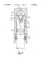
- FIG. 1is a sectional view of a bone lengthening device embodying the present invention and which is located in the femur.
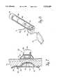
- FIG. 2is a detail view of an upper portion of the device shown in FIG. 1.
- FIG. 3is a detailed sectional view on an enlarged scale taken on the lines III--III of FIG. 2 of ratchet means for limiting movement of the device shown in FIG. 1.
- FIGS. 4, 5 and 6are detailed enlarged views of an alternative embodiment of the ratcheting mechanism including means for reversing the direction of the mechanism.
- FIG. 7is a detail view of means for supplying pressurized operating fluid to the device.
- FIG. 8is an alternative embodiment of the means for supplying pressurized operating fluid.
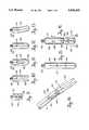
- FIG. 9is a threaded coupler for releasably joining selected distal tips to the piston.
- FIGS. 10 through 13are alternative distal tips for use with the device.
- FIG. 14is a view of the tip of FIG. 10 joined by the coupler to the piston.
- FIG. 15is another alternative distal tip.
- FIG. 16is still another alternative distal tip.
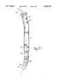
- FIG. 17is an articulated tibial nail.
- FIG. 1A device for lengthening bone and soft tissue in a human or other animal by incrementally extending the distance between discrete separated portions of the bone or tissue to permit continued growth between the portions will be seen in FIG. 1.
- the deviceis shown inserted into a human femur 2, although it could be another bone in a human or animal. Initially, a surgeon removes the soft, pulpy material in the medullar canal to produce an elongate opening. He then cuts the bone transversely as at gap 3 to receive an intramedullary nail or rod generally designated 4.
- the rodincludes a distal portion 6 and a proximal portion 8.
- the proximal portionhas formed in it a central bore 10 which leads to a cylinder 12 having an upper, domed shaped, fluid chamber 14.
- the proximal portionterminates at a point designated 16.
- a plate 18is securable by screws 20 to the femur.
- a one-way valve 22is threaded into the plate 18 and/or portion 8 and is secured by a nut 24 at the proximal end of the femur.
- a flexible conduit 26leads from the one-way valve 22 to an implantable reservoir 72 (FIG. 1) which, in turn, is actuated by a pump means 32, both elements to be described in greater detail hereinafter.
- the proximal portion 8 of the intramedullary nailis secured to the femur by screws 34.
- the distal portion 6 of the intramedullary nailis secured by screws 36 within the distal portion of the medullar canal and on its upper end is formed a piston 9.
- Ratchet teeth 40are formed in a line 42 in the piston 9.
- a collar 44is secured to the piston 9 by screws 48 and is received within an annular groove in the cylinder 12.
- a dog 46is received within a slot 49 in the collar 44 for movement inwardly and outwardly radially with regard to the piston and has teeth 50 engagable with the mating teeth 40 formed in the piston 9.
- a fluid tight gasket 51is fitted in a groove in the piston 9 and engages the wall of the cylinder 12.
- An annular, elastomeric shock absorbing element 52is engagable with the collar 44 and the top 55 of the annular groove.
- Lost motion between the piston 9 and the cylinder 12occurs to the extent of the gap 54 between the collar 44 and the annular groove as the patient's lower leg is moved, thus causing the lower cut portion of the femur to move or vibrate slightly relative to the upper cut portion.
- the pistonis permitted a small amount of lost motion relative to the cylinder, buffered by the shock absorber 52, which motion or vibration is beneficial to bone growth.
- the dog 46is urged to the left as seen in FIG. 3 by a compression spring 56 which is received within the collar 44.
- a compression spring 56which is received within the collar 44.
- the dog 46is moved slightly to the right as viewed in FIG. 3 by the teeth 40. Each tooth moves downwardly engaging the next adjacent tooth. This limits the motion of the distal end of the nail relative to the proximal portion to one direction.
- the pistoncan only move out of the cylinder upon admission of pressurized fluid to the chamber 14 above the piston head and not reverse direction. This will be done by the surgeon when the bone growth is completed.
- An elastomeric piston cap 60(FIG. 2) is secured by a screw 62 to the top of the piston member 9. The edges of the cap 62 maintain a seal against the inner wall 64 of the cylinder 12 which in conjunction with the annular seal 51 assures that there is no leakage of the saline operating fluid.
- the inventioncontemplates either an external or internal supply of operating fluid and either an external or internal pump, the internal or implantable version is the preferred embodiment.
- FIG. 7There will be seen an implantable supply of saline operating fluid 70 contained within an elastomeric diaphragm reservoir 72, implanted and secured by sutures 74 on an inner portion of the skin and muscle of the patient generally indicated 76.
- a ferromagnetic disk 78is secured in an upper domed portion 73 of the diaphragm reservoir.
- the implanted conduit 26which leads to the one-way valve 22 of the cylinder communicates with an opening 80 in the fluid reservoir 72.
- An external pump exciting member 82is engagable with the skin adjacent the ferromagnetic disk 78. It comprises an electromagnet 84, a battery 86 and a trigger 88 such that a surgeon or even a patient can trigger the exciting member to cause the ferromagnetic disk 78 to pulse toward and away from the electromagnet 84 to compress and relax the diaphragm reservoir to cause the saline fluid to pass through the conduit 26 through the one-way valve 22 and into the domed chamber 14 at the top of the piston.
- FIG. 8An alterative pump means 32a and reservoir 72a is shown in FIG. 8.
- the reservoir 72ais connected by a flexible conduit 26a to a pump 90 operated from a reversible geared motor 92.
- a programmable microprocessor 94through batteries 96, supplies signal to the motor 92 to pump fluid from the reservoir 72a through the conduit 26b into the upper domed chamber 14 of the cylinder 12.
- the motor 92being reversible, may also pump fluid back to the reservoir 72a.
- an inverted, bell shaped seal 100is provided which is mounted for flexure between a pair of hinged ratcheting wings 102, 104, having teeth 106 which are engagable with mating teeth 108 on the interior of the cylinder wall.
- the wings 102, 104are pivoted on a rod 112 received within bores in the top of the piston 9a.
- the pistonis cut away at 114 to accommodate the lower ends of the wings which pivot inwardly and outwardly under the control of a coiled spring 116.
- the implantable reservoir 72is pressurized either externally by the electromagnet 82 or, preferably, the reservoir 72a is pressurized by the microprocessor operated pump 90 because the system is reversible. This causes fluid to flow through the flexible tube 26 through the passageway 10 into the upper domed chamber 14 of the cylinder.
- the pressurized fluidacts against the seal 100 expanding its upper annular portion 101 to expand against the cylinder walls as shown in FIGS. 4 and 5.
- the pressureurges the wings 102, 104 apart against the force of its spring 116.
- the teeth 106engage the teeth 108 in the cylinder walls, one by one. Continued pressurization urges the piston 9a downwardly causing the bones to separate and permit new growth to take place.
- depressurization of the fluid above the pistonpermits the coiled spring 116 to squeeze the seal 100 together as shown in FIG. 6 with the pressurized saline fluid reversing direction in the passageway 10 and returning to the reservoir 72a.
- the reversible pump 90controls the fluid reversal.
- pressure on the distal end of the bonecan cause the piston 9a and the distal end of the bone to rise slightly, closing the gap 3 between it and the proximal portion of the bone.
- distal portion or tip 6 of the intermedullary nail or rod 4has been shown as one piece, the distal end may be removable to include alternative distal tips.
- FIG. 14shows the distal portion 6 having a female threaded portion 120 which receives the male threaded portion 122 of a coupler 124 which is also shown in FIG. 9. Axially opposite the male threaded portion 122 is a female threaded portion 126.
- the coupler of FIG. 9is shown as being an elastomeric material for flexibility and is made of any appropriate bio-compatible material.
- FIGS. 10-13show a plurality of replaceable distal tips 128 to 134.
- Tip 128is cylindrical and has an elongated slot 136 extending axially.
- Tip 130is also cylindrical having a spherical nose 138 and an elongate slot 140 running axially terminating short of the nose 138.
- Tip 132is cylindrical having a transverse bore 143.
- Tip 134is arcuate but has a cylindrical cross-section and a cylindrical transverse bore 144.
- the purposes of the slots 136 and 140are to permit the hole in the bone at its distal end to be drilled transversely to receive the pin 36 (FIG. 1) without precise location lengthwise of this bone.
- the elongate slots 136 and 140being able to accommodate the screw or the pin 36 at a point along their lengths.
- the additional purposes of the slotted tips as in FIGS. 10 and 11are such that when the piston is being urged toward the distal portion of the bone, i.e. away from the proximal portion, the pin 36 (FIG. 1) abuts the upper ends 142 of either of the slots 136, 140. Lost motion provided by the element 52 then comes into play.
- the slots 136, 140readily accommodates the reverse motion by causing the ends 142 of the slots 136, 140 to move away from the pin 36 which is fixed in the bone.
- the slotted tip 128can be removed without removal of the pin 36.
- the vibratory effect or the shock-absorbing effect of the element 51is negated. Whereas, with the tips of FIGS. 12 and 13, the pin 36 fits directly and firmly into the bores 143 or 144 would cause the tip to reciprocate.
- the arcuate configuration of the tip shown in FIG. 13is to fit within the enlarged intermedullary cavity in the bone shown at the lower portion of FIG. 1.
- the axial passageways 135are located in the tips to aid the surgeon in removing the tips should they become inadvertently lodged in the bond by the use of a "fishing wire.”
- FIG. 15discloses a somewhat longer tip 137 having two transverse bores 146 and 148 for receiving two pins or screws 36.
- FIG. 16discloses yet another embodiment of another removable tip 141 which does not require the bone to be drilled to receive the locking pin 36.
- a pair of feet 150, 152are pivoted at 154 and 156 in slots 160, 162. They are urged outwardly from the slots by compression springs 164, 166 such that when they are inserted into the distal end of the bone the feet engage the interior of the medullar canal locking the tip in place.
- the feetOn inserting the tip 140, the feet are held in place by a removable band 168 which may be either removed or slid upwardly by the surgeon to permit the feet to be biased into the locking position.
- FIG. 17discloses a device which is usable in fixating or extending the length of the tibia.
- the tibial nailincludes a piston 9, screws 20 and 34, flexible conduit 26, ratcheting mechanism 42, all functioning as in the FIG. 1 embodiment.
- the lower end 170 of the pistonis removable as is the coupling device disclosed in FIG. 9.
- the distal tip 172is articulable relative to the piston 9 by way of a ball and socket joint 174 joining the tip 172 to the lower end 170 of the piston. This is to facilitate entry of the nail into the tibia because of its unique shape.
Landscapes
- Health & Medical Sciences (AREA)
- Orthopedic Medicine & Surgery (AREA)
- Life Sciences & Earth Sciences (AREA)
- Surgery (AREA)
- Animal Behavior & Ethology (AREA)
- Veterinary Medicine (AREA)
- Public Health (AREA)
- Engineering & Computer Science (AREA)
- Biomedical Technology (AREA)
- Heart & Thoracic Surgery (AREA)
- General Health & Medical Sciences (AREA)
- Molecular Biology (AREA)
- Medical Informatics (AREA)
- Nuclear Medicine, Radiotherapy & Molecular Imaging (AREA)
- Neurology (AREA)
- Cardiology (AREA)
- Oral & Maxillofacial Surgery (AREA)
- Transplantation (AREA)
- Vascular Medicine (AREA)
- Surgical Instruments (AREA)
- Prostheses (AREA)
Abstract
Description
This is a continuation-in-part application of copending application U.S. patent application Ser. No. 08/018,820 filed Feb. 18, 1993, now U.S. Pat. No. 5,350,379.
This invention pertains to apparatus for extending or lengthening bones and for fracture fixation and is particularly applicable to lengthening of human bones. There are many instances where a human being has one limb, particularly a leg, which is shorter than the other which could be congenital or due to an accident.
A comminuted fracture is one in which the bone is broken into many small pieces, some in the form of splinters which overlap one another.
It has been found possible to lengthen the deformed or shortened limb or permit the comminuted fracture to heal by devices which extend a proximal portion of a bone which has been severed or splintered from a distal portion. Such devices move the distal portion of the bone away from the proximal portion in small increments. This involves extending the gap between the severed bone portions in increments of approximately 1/4 mm at a time. When the bones are thus separated, new bone tissue grows in the extended gap as well as soft tissue surrounding the bone. It is possible to lengthen a bone such as afemur 10 or more centimeters over a period of a few months.
One such device was developed in the USSR by Gavriil A. Ilizarov et al. which essentially is an extendable cage which fits externally around a limb. The distal end of the cage is incrementally extended from the proximal portion mechanically. One of the problems with this type of device is that a plurality of pins are inserted through the muscle of the limb, and into both portions of the bone. With the proximal portion of the limb "anchored" by the pins in the cage, force is transmitted through the pins to pull the distal portion away from the anchored portion. Such a device is described in U.S. Pat. No. 4,615,338. One of the problems created by this type of device is that numerous incisions are created in a limb by the pins which are susceptible to infection and that the pins are continually pulling on the flesh. Another disadvantage is that the wearing of a cage over a period of months severely limits the mobility of the patient.
Numerous other devices employ an elongated rod or nail known as an intramedullary rod or nail. Such devices are inserted into the marrow cavity or medullary passage of the bone. These rods are often threaded and are anchored to the bone from within the medullar canal and are incrementally moved by nuts or ratchet means to incrementally continue separating bone portions. One such early device is shown in U.S. Pat. No. 3,986,504 to Avila. The ratcheting or extending of the threaded rod is accomplished externally by ratcheting mechanism or wrenches. Again, this type of device lends itself to infection.
Other types of devices have been developed also in the USSR by Alexander Bliskunov and employ ratcheting devices which are implanted internally and are operated by the patient himself who moves portions of his body to activate the ratcheting mechanism. One problem with this type of device is that accidental movement or excessive movement can cause too much bone separation, disturbing the growth pattern. It is to these problems that the present invention is directed. Another objective is to provide a completely implantable, hydraulically operated mechanism with as little opportunity for infection as possible and which is substantially foolproof in operation.
At least one hydraulically operated device has been discovered by Gotz and Schellmann, "Continuous Lengthening of the Femur by Intramedullary Stabilization", Archiv. orthopadische Unfall-Chirugie 82:305-310, J. F. Bergmann Publishing, Munich (1975).
A device for lengthening bone and tissue in a human or animal is disclosed for incrementally extending the distance between discrete separated portions of the bone to permit continued growth between the separated portions. It includes an intramedullary nail having a distal portion and a proximal portion. The proximal portion of the nail is secured within the intramedullary canal of the bone at the proximal end thereof and the distal portion of the nail is secured within the intramedullary canal at the distal end thereof. A hydraulic cylinder is connected to the proximal portion and a piston moveable in the cylinder is connected to the distal end of the nail. There is a supply of operating fluid in communication with the cylinder which may be implantable or external and ratcheting mechanism is located between the proximal and distal portions of the nail, i.e., the piston and cylinder, to limit their relative movement to one direction.
An alternative ratcheting mechanism, however, permits the proximal and distal portions of the nail (i.e., piston and cylinder) to reverse directions when the pressure of the operating fluid is released.
A shock absorbing member is interposed between the piston and the cylinder and cooperates with lost motion mechanism to provide a small amount of buffered lost motion, creating an environment to enhance growth between the separated portions.
The pressurizable fluid is contained in a reservoir which may also be implantable or external and pumped either manually or from an external signalling device or an internal pump controlled by an implantable battery operated microprocessor.
The distal portion of the nail may be made as removable tips of varying configurations. They may be secured, as by screw coupling, directly to the distal portion of the nail or an elastomeric flexible coupling may be interposed between the distal portion of the nail and the discrete tip.
The tips may be slotted as from their free end toward their distal portion to give the surgeon a degree of freedom as to where he drills the bone for the screw.
The tips may be either straight or arcuate depending upon the shape of the medullar canal into which it is to be inserted. A special tibulanail is disclosed. It has an articulated distal tip.
There may be more than one bores or holes passing transversely through the tips to permit the use of more than one screw to secure it firmly to the bone.
A slot may be formed in the tip which does not extend out of the tip end also to permit the surgeon a degree of freedom when drilling the hole for the securing screw.
The tip may be provided with a pair of feet pivoted on the tip in slots. They are normally urged outwardly from the slots by compression springs such that when they are inserted into the distal end of the bone the feet engage the interior of the medullar canal locking the tip in place. On insertion, the feet would be held in the slots by a removable band.
It will be understood that the device, while illustrated as lengthening the femur, can with simple modification be adjusted to lengthen generally elongated long bones.
The above and other features of the invention, including various and novel details of construction and combinations of parts will now be more particularly described with reference to the accompanying drawings and pointed out in the claims. It will be understood that the particular bone and tissue lengthening device embodying the invention is shown by way of illustration only and not as a limitation of the invention. The principles and features of this invention may be employed in varied and numerous embodiments without departing from the scope of the invention.
FIG. 1 is a sectional view of a bone lengthening device embodying the present invention and which is located in the femur.
FIG. 2 is a detail view of an upper portion of the device shown in FIG. 1.
FIG. 3 is a detailed sectional view on an enlarged scale taken on the lines III--III of FIG. 2 of ratchet means for limiting movement of the device shown in FIG. 1.
FIGS. 4, 5 and 6 are detailed enlarged views of an alternative embodiment of the ratcheting mechanism including means for reversing the direction of the mechanism.
FIG. 7 is a detail view of means for supplying pressurized operating fluid to the device.
FIG. 8 is an alternative embodiment of the means for supplying pressurized operating fluid.
FIG. 9 is a threaded coupler for releasably joining selected distal tips to the piston.
FIGS. 10 through 13 are alternative distal tips for use with the device.
FIG. 14 is a view of the tip of FIG. 10 joined by the coupler to the piston.
FIG. 15 is another alternative distal tip.
FIG. 16 is still another alternative distal tip.
FIG. 17 is an articulated tibial nail.
A device for lengthening bone and soft tissue in a human or other animal by incrementally extending the distance between discrete separated portions of the bone or tissue to permit continued growth between the portions will be seen in FIG. 1. The device is shown inserted into ahuman femur 2, although it could be another bone in a human or animal. Initially, a surgeon removes the soft, pulpy material in the medullar canal to produce an elongate opening. He then cuts the bone transversely as atgap 3 to receive an intramedullary nail or rod generally designated 4.
The rod includes adistal portion 6 and aproximal portion 8. The proximal portion has formed in it acentral bore 10 which leads to acylinder 12 having an upper, domed shaped,fluid chamber 14. The proximal portion terminates at a point designated 16. Aplate 18 is securable byscrews 20 to the femur. A one-way valve 22 is threaded into theplate 18 and/orportion 8 and is secured by anut 24 at the proximal end of the femur. Aflexible conduit 26 leads from the one-way valve 22 to an implantable reservoir 72 (FIG. 1) which, in turn, is actuated by a pump means 32, both elements to be described in greater detail hereinafter. Theproximal portion 8 of the intramedullary nail is secured to the femur by screws 34. Thedistal portion 6 of the intramedullary nail is secured byscrews 36 within the distal portion of the medullar canal and on its upper end is formed apiston 9. Ratchetteeth 40 are formed in aline 42 in thepiston 9.
Acollar 44 is secured to thepiston 9 byscrews 48 and is received within an annular groove in thecylinder 12. Adog 46 is received within aslot 49 in thecollar 44 for movement inwardly and outwardly radially with regard to the piston and hasteeth 50 engagable with themating teeth 40 formed in thepiston 9. A fluidtight gasket 51 is fitted in a groove in thepiston 9 and engages the wall of thecylinder 12. An annular, elastomericshock absorbing element 52 is engagable with thecollar 44 and the top 55 of the annular groove.
Lost motion between thepiston 9 and thecylinder 12 occurs to the extent of thegap 54 between thecollar 44 and the annular groove as the patient's lower leg is moved, thus causing the lower cut portion of the femur to move or vibrate slightly relative to the upper cut portion. In other words, the piston is permitted a small amount of lost motion relative to the cylinder, buffered by theshock absorber 52, which motion or vibration is beneficial to bone growth.
Thedog 46 is urged to the left as seen in FIG. 3 by acompression spring 56 which is received within thecollar 44. When thepiston 9 and, hence, the distal portion of the bone, is urged downwardly by pressurized fluid entering thechamber 14, thedog 46 is moved slightly to the right as viewed in FIG. 3 by theteeth 40. Each tooth moves downwardly engaging the next adjacent tooth. This limits the motion of the distal end of the nail relative to the proximal portion to one direction. Thus, the piston can only move out of the cylinder upon admission of pressurized fluid to thechamber 14 above the piston head and not reverse direction. This will be done by the surgeon when the bone growth is completed.
An elastomeric piston cap 60 (FIG. 2) is secured by ascrew 62 to the top of thepiston member 9. The edges of thecap 62 maintain a seal against the inner wall 64 of thecylinder 12 which in conjunction with theannular seal 51 assures that there is no leakage of the saline operating fluid.
Whereas the invention contemplates either an external or internal supply of operating fluid and either an external or internal pump, the internal or implantable version is the preferred embodiment.
Pump means 32 andreservoir 72 will now be described referring next to FIG. 7. There will be seen an implantable supply ofsaline operating fluid 70 contained within anelastomeric diaphragm reservoir 72, implanted and secured bysutures 74 on an inner portion of the skin and muscle of the patient generally indicated 76. Aferromagnetic disk 78 is secured in an upperdomed portion 73 of the diaphragm reservoir. The implantedconduit 26 which leads to the one-way valve 22 of the cylinder communicates with anopening 80 in thefluid reservoir 72.
An external pumpexciting member 82 is engagable with the skin adjacent theferromagnetic disk 78. It comprises anelectromagnet 84, abattery 86 and atrigger 88 such that a surgeon or even a patient can trigger the exciting member to cause theferromagnetic disk 78 to pulse toward and away from theelectromagnet 84 to compress and relax the diaphragm reservoir to cause the saline fluid to pass through theconduit 26 through the one-way valve 22 and into thedomed chamber 14 at the top of the piston.
An alterative pump means 32a and reservoir 72a is shown in FIG. 8. The reservoir 72a is connected by a flexible conduit 26a to apump 90 operated from a reversible gearedmotor 92. Aprogrammable microprocessor 94, throughbatteries 96, supplies signal to themotor 92 to pump fluid from the reservoir 72a through the conduit 26b into the upperdomed chamber 14 of thecylinder 12. Themotor 92, being reversible, may also pump fluid back to the reservoir 72a.
With reference to FIGS. 4, 5 and 6, mechanism for reversing the direction of the piston 9a within the cylinder will now be described. At the top of the piston, an inverted, bell shapedseal 100 is provided which is mounted for flexure between a pair of hinged ratchetingwings teeth 106 which are engagable withmating teeth 108 on the interior of the cylinder wall. Thewings rod 112 received within bores in the top of the piston 9a. The piston is cut away at 114 to accommodate the lower ends of the wings which pivot inwardly and outwardly under the control of acoiled spring 116.
When it is desired to incrementally separate the proximal and distal portions of the bone, theimplantable reservoir 72 is pressurized either externally by theelectromagnet 82 or, preferably, the reservoir 72a is pressurized by the microprocessor operatedpump 90 because the system is reversible. This causes fluid to flow through theflexible tube 26 through thepassageway 10 into the upperdomed chamber 14 of the cylinder. The pressurized fluid acts against theseal 100 expanding its upperannular portion 101 to expand against the cylinder walls as shown in FIGS. 4 and 5. The pressure urges thewings spring 116. Theteeth 106 engage theteeth 108 in the cylinder walls, one by one. Continued pressurization urges the piston 9a downwardly causing the bones to separate and permit new growth to take place.
If, for some reason, the bone portions have been separated too much or it is desired to terminate the bone growth, depressurization of the fluid above the piston permits thecoiled spring 116 to squeeze theseal 100 together as shown in FIG. 6 with the pressurized saline fluid reversing direction in thepassageway 10 and returning to the reservoir 72a. Thereversible pump 90 controls the fluid reversal.
Without using thepump 90, with theteeth 106 on thewings teeth 108 on the inner cylinder walls, pressure on the distal end of the bone, as for example, by the orthopedist applying counter pressure, can cause the piston 9a and the distal end of the bone to rise slightly, closing thegap 3 between it and the proximal portion of the bone.
A plurality of distal tips and adaptors will now be described.
Whereas the distal portion ortip 6 of the intermedullary nail orrod 4 has been shown as one piece, the distal end may be removable to include alternative distal tips.
FIG. 14 shows thedistal portion 6 having a female threadedportion 120 which receives the male threadedportion 122 of acoupler 124 which is also shown in FIG. 9. Axially opposite the male threadedportion 122 is a female threadedportion 126.
The coupler of FIG. 9 is shown as being an elastomeric material for flexibility and is made of any appropriate bio-compatible material.
FIGS. 10-13 show a plurality of replaceabledistal tips 128 to 134.Tip 128 is cylindrical and has an elongatedslot 136 extending axially.Tip 130 is also cylindrical having aspherical nose 138 and anelongate slot 140 running axially terminating short of thenose 138.Tip 132 is cylindrical having atransverse bore 143.Tip 134 is arcuate but has a cylindrical cross-section and a cylindricaltransverse bore 144.
The purposes of theslots elongate slots pin 36 at a point along their lengths.
The additional purposes of the slotted tips as in FIGS. 10 and 11 are such that when the piston is being urged toward the distal portion of the bone, i.e. away from the proximal portion, the pin 36 (FIG. 1) abuts the upper ends 142 of either of theslots element 52 then comes into play. Theslots ends 142 of theslots pin 36 which is fixed in the bone. In addition, the slottedtip 128 can be removed without removal of thepin 36. By use of the tips of the embodiment of FIGS. 10 and 11, the vibratory effect or the shock-absorbing effect of theelement 51 is negated. Whereas, with the tips of FIGS. 12 and 13, thepin 36 fits directly and firmly into thebores
The arcuate configuration of the tip shown in FIG. 13 is to fit within the enlarged intermedullary cavity in the bone shown at the lower portion of FIG. 1.
Theaxial passageways 135 are located in the tips to aid the surgeon in removing the tips should they become inadvertently lodged in the bond by the use of a "fishing wire."
FIG. 15 discloses a somewhatlonger tip 137 having twotransverse bores
FIG. 16 discloses yet another embodiment of anotherremovable tip 141 which does not require the bone to be drilled to receive the lockingpin 36. A pair offeet slots tip 140, the feet are held in place by aremovable band 168 which may be either removed or slid upwardly by the surgeon to permit the feet to be biased into the locking position.
FIG. 17 discloses a device which is usable in fixating or extending the length of the tibia. As with the FIG. 1 device, the tibial nail includes apiston 9, screws 20 and 34,flexible conduit 26,ratcheting mechanism 42, all functioning as in the FIG. 1 embodiment. Thelower end 170 of the piston is removable as is the coupling device disclosed in FIG. 9. Thedistal tip 172 is articulable relative to thepiston 9 by way of a ball and socket joint 174 joining thetip 172 to thelower end 170 of the piston. This is to facilitate entry of the nail into the tibia because of its unique shape.
Claims (24)
1. A device for lengthening bone and tissue and for fracture fixation in a human or animal by incrementally extending the distance between discrete separated portions of the bone to permit continued growth between the separated portions comprising:
an intramedullary nail having a distal portion and a proximal portion;
the proximal portion of the nail being securable within the medullar canal of the bone at the proximal end of the bone;
the distal portion of the nail being securable within the medullar canal of the bone at the distal end of the bone;
a hydraulic cylinder connected to the proximal portion of the nail;
a piston connected to the distal portion of the nail and movable in the cylinder;
a supply of implantable operating fluid in communication with the cylinder;
ratcheting mechanism between the piston and cylinder to limit their relative movement and that of the bone portions to which they are secured to one direction; and
a removable slotted tip and releasable securing means for securing the tip to the distal portion of the nail.
2. A device according to claim 1 further comprising a pump in communication with the implantable supply of operating fluid to pump the operating fluid.
3. A device according to claim 1 wherein the releasable securing means is a flexible coupling.
4. A device according to claim 1 wherein the removable tip has spring biased feet for engaging the medullar canal.
5. A device according to claim 1 wherein the releasable securing means is articulable.
6. A device for lengthening bone and tissue and for fracture fixation in a human or animal by incrementally extending the distance between discrete separated portions of the bone to permit continued growth between the separated portions comprising:
an intramedullary nail having a distal portion and a proximal portion;
the proximal portion of the nail being securable within the medullar canal of the bone at the proximal end of the bone;
the distal portion of the nail being securable within the medullar canal of the bone at the distal end of the bone;
a hydraulic cylinder connected to the proximal portion of the nail;
a piston connected to the distal portion of the nail and movable in the cylinder;
a supply of implantable operating fluid in communication with the cylinder;
a shock absorbing element operatively engagable with both the piston and the cylinder;
means to permit limited lost motion between the piston and the cylinder against the shock absorbing element in the direction of movement of the piston to stimulate bone growth between the separated portions of the bone; and
a removable slotted tip and releasable securing means for securing the tip to the distal portion of the nail.
7. A device according to claim 6 further comprising a pump in communication with the implantable supply of operating fluid to pump the operating fluid.
8. A device according to claim 6 wherein the releasable securing means is a flexible coupling.
9. A device according to claim 6 wherein the removable tip has spring biased feet for engaging the medullar canal.
10. A device according to claim 6 wherein the releasable securing means is articulable.
11. A device for lengthening bone and tissue and for fracture fixation in a human or animal by incrementally extending the distance between discrete separated portions of the bone to permit continued growth between the separated portions comprising:
an intramedullary nail having a distal portion and a proximal portion;
the proximal portion of the nail being securable within the medullar canal of the bone at the proximal end of the bone;
the distal portion of the nail being securable within the medullar canal of the bone at the distal end of the bone;
a hydraulic cylinder connected to the proximal portion of the nail;
a piston connected to the distal portion of the nail and movable in the cylinder;
a supply of implantable operating fluid in communication with the cylinder;
ratcheting mechanism between the piston and cylinder to limit their relative movement and that of the bone portions to which they are secured to one direction;
mechanism to permit the piston to reverse directions relative to the cylinder when the pressure of the operating fluid is released; and
a removable slotted tip and releasable securing means for securing the tip to the distal portion of the nail.
12. A device according to claim 11 further comprising a pump in communication with the implantable supply of operating fluid to pump the operating fluid.
13. A device according to claim 11 wherein the releasable securing means is a flexible coupling.
14. A device according to claim 11 wherein the removable tip has spring biased feet for engaging the medullar canal.
15. A device according to claim 11 wherein the releasable securing means is articulable.
16. A device for the fixation of a bone in a human or animal, which bone is fractured and separated into a distal end and a proximal end, the device comprising:
a distal elongate member being securable within the medullary canal of the bone at the distal end of the bone;
a proximal elongate member being securable within the medullary canal of the bone at the proximal end of the bone;
a coupling mating the distal and proximal members to form an intramedullary nail having a maximum length which permits relative longitudinal motion between the distal and proximal members, the coupling being responsive to longitudinal compression to shorten the length of the formed nail; and
a buffering member disposed within the coupling between the distal and proximal members to permit lost motion to take place between the distal and proximal members, thereby facilitating continued growth between the separated portions of the bone.
17. A device according to claim 16 wherein the buffering member is a shock absorber.
18. A device according to claim 16 wherein the buffering member is elastomeric.
19. A device according to claim 16 wherein the buffering member includes an annular ring of an elastomeric material.
20. A device according to claim 16 having a removable tip securable to the distal elongate member.
21. A device according to claim 16 having a removable tip and a flexible coupling joining the removable tip to the distal elongate member.
22. A device according to claim 16 having a removable slotted tip securable to the distal elongate member.
23. A device according to claim 16 having a removable tip with spring biased feet for engaging the medullar canal, the tip being securable to the distal elongate member.
24. A device according to claim 16 having a removable tip and articulable means for joining the tip to the distal elongate member.
Priority Applications (9)
| Application Number | Priority Date | Filing Date | Title |
|---|---|---|---|
| US08/200,073US5536269A (en) | 1993-02-18 | 1994-02-22 | Bone and tissue lengthening device |
| TW083107984ATW323227B (en) | 1994-02-22 | 1994-08-29 | |
| CN94116875ACN1119928A (en) | 1994-02-22 | 1994-08-30 | Bone and tissue lengthening device |
| KR1019940026588AKR950024744A (en) | 1994-02-22 | 1994-10-18 | Bone and Tissue Extenders |
| EP95911702AEP0746257A1 (en) | 1994-02-22 | 1995-02-13 | Bone and tissue lengthening device |
| JP7521872AJPH09512717A (en) | 1994-02-22 | 1995-02-13 | Bone and tissue stretcher |
| PCT/US1995/001798WO1995022292A1 (en) | 1994-02-22 | 1995-02-13 | Bone and tissue lengthening device |
| AU19172/95AAU1917295A (en) | 1994-02-22 | 1995-02-13 | Bone and tissue lengthening device |
| CA002184006ACA2184006A1 (en) | 1994-02-22 | 1995-02-13 | Bone and tissue lengthening device |
Applications Claiming Priority (2)
| Application Number | Priority Date | Filing Date | Title |
|---|---|---|---|
| US08/018,820US5350379A (en) | 1993-02-18 | 1993-02-18 | Bone and tissue lengthening device |
| US08/200,073US5536269A (en) | 1993-02-18 | 1994-02-22 | Bone and tissue lengthening device |
Related Parent Applications (1)
| Application Number | Title | Priority Date | Filing Date |
|---|---|---|---|
| US08/018,820Continuation-In-PartUS5350379A (en) | 1993-02-18 | 1993-02-18 | Bone and tissue lengthening device |
Publications (1)
| Publication Number | Publication Date |
|---|---|
| US5536269Atrue US5536269A (en) | 1996-07-16 |
Family
ID=22740212
Family Applications (1)
| Application Number | Title | Priority Date | Filing Date |
|---|---|---|---|
| US08/200,073Expired - Fee RelatedUS5536269A (en) | 1993-02-18 | 1994-02-22 | Bone and tissue lengthening device |
Country Status (9)
| Country | Link |
|---|---|
| US (1) | US5536269A (en) |
| EP (1) | EP0746257A1 (en) |
| JP (1) | JPH09512717A (en) |
| KR (1) | KR950024744A (en) |
| CN (1) | CN1119928A (en) |
| AU (1) | AU1917295A (en) |
| CA (1) | CA2184006A1 (en) |
| TW (1) | TW323227B (en) |
| WO (1) | WO1995022292A1 (en) |
Cited By (77)
| Publication number | Priority date | Publication date | Assignee | Title |
|---|---|---|---|---|
| WO1998004302A1 (en)* | 1996-07-26 | 1998-02-05 | Gravlee Joseph F Jr | Hypodermic needle |
| WO1998047438A1 (en)* | 1997-04-24 | 1998-10-29 | Augustin Betz | Bone traction device |
| US6033412A (en)* | 1997-04-03 | 2000-03-07 | Losken; H. Wolfgang | Automated implantable bone distractor for incremental bone adjustment |
| US6416516B1 (en)* | 1999-02-16 | 2002-07-09 | Wittenstein Gmbh & Co. Kg | Active intramedullary nail for the distraction of bone parts |
| US6758673B2 (en) | 2001-12-05 | 2004-07-06 | Ofir Fromovich | Periosteal distraction |
| US20040138663A1 (en)* | 2001-05-23 | 2004-07-15 | Yona Kosashvili | Magnetically-actuable intramedullary device |
| WO2004058083A1 (en)* | 2002-12-16 | 2004-07-15 | Smith John T | Implantable distraction device |
| US20050234448A1 (en)* | 2004-03-19 | 2005-10-20 | Mccarthy James | Implantable bone-lengthening device |
| US20050261779A1 (en)* | 2003-11-17 | 2005-11-24 | Meyer Rudolf X | Expansible rod-type prosthesis and external magnetic apparatus |
| US20060004459A1 (en)* | 2004-06-30 | 2006-01-05 | Hazebrouck Stephen A | Adjustable orthopaedic prosthesis and associated method |
| US20060069447A1 (en)* | 2004-09-30 | 2006-03-30 | Disilvestro Mark R | Adjustable, remote-controllable orthopaedic prosthesis and associated method |
| US20060235424A1 (en)* | 2005-04-01 | 2006-10-19 | Foster-Miller, Inc. | Implantable bone distraction device and method |
| US20070005141A1 (en)* | 2005-06-30 | 2007-01-04 | Jason Sherman | Apparatus, system, and method for transcutaneously transferring energy |
| US20070004994A1 (en)* | 2005-06-30 | 2007-01-04 | Jason Sherman | Apparatus, system, and method for transcutaneously transferring energy |
| US20070016202A1 (en)* | 2005-07-12 | 2007-01-18 | David Kraft | Intramedullar distraction device with user actuated distraction |
| US20070239282A1 (en)* | 2006-04-07 | 2007-10-11 | Caylor Edward J Iii | System and method for transmitting orthopaedic implant data |
| US20070270660A1 (en)* | 2006-03-29 | 2007-11-22 | Caylor Edward J Iii | System and method for determining a location of an orthopaedic medical device |
| US20080009869A1 (en)* | 2004-12-31 | 2008-01-10 | Andre Schlienger | Intramedullary nail |
| US20080051779A1 (en)* | 2006-08-02 | 2008-02-28 | The Nemours Foundation | Force-controlled autodistraction |
| US20080071146A1 (en)* | 2006-09-11 | 2008-03-20 | Caylor Edward J | System and method for monitoring orthopaedic implant data |
| US20090005876A1 (en)* | 2007-06-29 | 2009-01-01 | Dietz Terry L | Tibial tray assembly having a wireless communication device |
| US20090062798A1 (en)* | 2006-11-06 | 2009-03-05 | Janet Conway | Internal bone transport |
| US20090088766A1 (en)* | 2007-10-01 | 2009-04-02 | Physical Sciences, Inc. | Distraction Osteogenesis Methods and Devices |
| US7588577B2 (en) | 2004-07-15 | 2009-09-15 | Wright Medical Technology, Inc. | Guide assembly for intramedullary fixation and method of using the same |
| US20090281542A1 (en)* | 2008-05-12 | 2009-11-12 | Warsaw Orthopedics, Inc. | Elongated members with expansion chambers for treating bony memebers |
| US7713271B2 (en) | 2000-09-22 | 2010-05-11 | Piper Medical, Inc. | Intramedullary interlocking fixation devices for the distal radius |
| US20110060336A1 (en)* | 2009-09-04 | 2011-03-10 | Ellipse Technologies, Inc. | Bone growth device and method |
| US20110137347A1 (en)* | 2009-12-01 | 2011-06-09 | Synthes Usa, Llc | Non-fusion scoliosis expandable spinal rod |
| US8015024B2 (en) | 2006-04-07 | 2011-09-06 | Depuy Products, Inc. | System and method for managing patient-related data |
| US20120226278A1 (en)* | 2010-09-20 | 2012-09-06 | Nardini Reto | Intramedullary Nail |
| US8715282B2 (en) | 2011-02-14 | 2014-05-06 | Ellipse Technologies, Inc. | System and method for altering rotational alignment of bone sections |
| US8771283B2 (en) | 2007-12-17 | 2014-07-08 | Wright Medical Technology, Inc. | Guide assembly for intramedullary fixation and method of using the same |
| US20140243825A1 (en)* | 2011-02-17 | 2014-08-28 | Mylad Orthopedic Solutions LLC | Compressible device assembly and associated method for facilitating healing between bones |
| US8961567B2 (en) | 2010-11-22 | 2015-02-24 | DePuy Synthes Products, LLC | Non-fusion scoliosis expandable spinal rod |
| US9451971B2 (en) | 2004-07-15 | 2016-09-27 | Agilent Technologies, Inc. | Intramedullary fixation assembly and devices and methods for installing the same |
| US9744057B2 (en) | 2000-05-09 | 2017-08-29 | Ben-Zion Karmon | Device to deliver flowable material to the sinus |
| US9827025B2 (en) | 2015-11-20 | 2017-11-28 | Globus Medical, Inc. | Expandable intramedullary systems and methods of using the same |
| US9974581B2 (en) | 2015-11-20 | 2018-05-22 | Globus Medical, Inc. | Expandable intramedullary systems and methods of using the same |
| US10016220B2 (en) | 2011-11-01 | 2018-07-10 | Nuvasive Specialized Orthopedics, Inc. | Adjustable magnetic devices and methods of using same |
| US10039661B2 (en) | 2006-10-20 | 2018-08-07 | Nuvasive Specialized Orthopedics, Inc. | Adjustable implant and method of use |
| US10092333B2 (en) | 2015-11-20 | 2018-10-09 | Globus Medical, Inc. | Expandable intramedullary systems and methods of using the same |
| US20180317980A1 (en)* | 2008-10-31 | 2018-11-08 | Peter Forsell | Device and method for bone adjustment with anchoring function |
| US10238427B2 (en) | 2015-02-19 | 2019-03-26 | Nuvasive Specialized Orthopedics, Inc. | Systems and methods for vertebral adjustment |
| US10271885B2 (en) | 2014-12-26 | 2019-04-30 | Nuvasive Specialized Orthopedics, Inc. | Systems and methods for distraction |
| US10349995B2 (en) | 2007-10-30 | 2019-07-16 | Nuvasive Specialized Orthopedics, Inc. | Skeletal manipulation method |
| US10405891B2 (en) | 2010-08-09 | 2019-09-10 | Nuvasive Specialized Orthopedics, Inc. | Maintenance feature in magnetic implant |
| US10478232B2 (en) | 2009-04-29 | 2019-11-19 | Nuvasive Specialized Orthopedics, Inc. | Interspinous process device and method |
| US10517643B2 (en) | 2009-02-23 | 2019-12-31 | Nuvasive Specialized Orthopedics, Inc. | Non-invasive adjustable distraction system |
| US10617453B2 (en) | 2015-10-16 | 2020-04-14 | Nuvasive Specialized Orthopedics, Inc. | Adjustable devices for treating arthritis of the knee |
| US10660675B2 (en) | 2010-06-30 | 2020-05-26 | Nuvasive Specialized Orthopedics, Inc. | External adjustment device for distraction device |
| US10729470B2 (en) | 2008-11-10 | 2020-08-04 | Nuvasive Specialized Orthopedics, Inc. | External adjustment device for distraction device |
| US10743794B2 (en) | 2011-10-04 | 2020-08-18 | Nuvasive Specialized Orthopedics, Inc. | Devices and methods for non-invasive implant length sensing |
| US10751094B2 (en) | 2013-10-10 | 2020-08-25 | Nuvasive Specialized Orthopedics, Inc. | Adjustable spinal implant |
| US10835290B2 (en) | 2015-12-10 | 2020-11-17 | Nuvasive Specialized Orthopedics, Inc. | External adjustment device for distraction device |
| US10918425B2 (en) | 2016-01-28 | 2021-02-16 | Nuvasive Specialized Orthopedics, Inc. | System and methods for bone transport |
| US11045289B2 (en) | 2015-12-29 | 2021-06-29 | Ben Zion Karmon | Devices and methods for elevating the Schneiderian membrane |
| US11191579B2 (en) | 2012-10-29 | 2021-12-07 | Nuvasive Specialized Orthopedics, Inc. | Adjustable devices for treating arthritis of the knee |
| US11202707B2 (en) | 2008-03-25 | 2021-12-21 | Nuvasive Specialized Orthopedics, Inc. | Adjustable implant system |
| US11246694B2 (en) | 2014-04-28 | 2022-02-15 | Nuvasive Specialized Orthopedics, Inc. | System for informational magnetic feedback in adjustable implants |
| USRE49061E1 (en) | 2012-10-18 | 2022-05-10 | Nuvasive Specialized Orthopedics, Inc. | Intramedullary implants for replacing lost bone |
| US11357547B2 (en) | 2014-10-23 | 2022-06-14 | Nuvasive Specialized Orthopedics Inc. | Remotely adjustable interactive bone reshaping implant |
| US11357549B2 (en) | 2004-07-02 | 2022-06-14 | Nuvasive Specialized Orthopedics, Inc. | Expandable rod system to treat scoliosis and method of using the same |
| US11426220B2 (en) | 2017-10-11 | 2022-08-30 | Howmedica Osteonics Corp. | Humeral fixation plate guides |
| US11577097B2 (en) | 2019-02-07 | 2023-02-14 | Nuvasive Specialized Orthopedics, Inc. | Ultrasonic communication in medical devices |
| US11589901B2 (en) | 2019-02-08 | 2023-02-28 | Nuvasive Specialized Orthopedics, Inc. | External adjustment device |
| US20230190342A1 (en)* | 2021-12-17 | 2023-06-22 | Mark Robert BRINKER | Surgical device |
| US11696836B2 (en) | 2013-08-09 | 2023-07-11 | Nuvasive, Inc. | Lordotic expandable interbody implant |
| US11737787B1 (en) | 2021-05-27 | 2023-08-29 | Nuvasive, Inc. | Bone elongating devices and methods of use |
| US11766252B2 (en) | 2013-07-31 | 2023-09-26 | Nuvasive Specialized Orthopedics, Inc. | Noninvasively adjustable suture anchors |
| US11801187B2 (en) | 2016-02-10 | 2023-10-31 | Nuvasive Specialized Orthopedics, Inc. | Systems and methods for controlling multiple surgical variables |
| US11806054B2 (en) | 2021-02-23 | 2023-11-07 | Nuvasive Specialized Orthopedics, Inc. | Adjustable implant, system and methods |
| US11819380B2 (en) | 2016-10-13 | 2023-11-21 | Ben Zion Karmon | Devices for tissue augmentation |
| US11839410B2 (en) | 2012-06-15 | 2023-12-12 | Nuvasive Inc. | Magnetic implants with improved anatomical compatibility |
| US11857226B2 (en) | 2013-03-08 | 2024-01-02 | Nuvasive Specialized Orthopedics | Systems and methods for ultrasonic detection of device distraction |
| US11925389B2 (en) | 2008-10-13 | 2024-03-12 | Nuvasive Specialized Orthopedics, Inc. | Spinal distraction system |
| US12023073B2 (en) | 2021-08-03 | 2024-07-02 | Nuvasive Specialized Orthopedics, Inc. | Adjustable implant |
| US12213708B2 (en) | 2020-09-08 | 2025-02-04 | Nuvasive Specialized Orthopedics, Inc. | Remote control module for adjustable implants |
Families Citing this family (11)
| Publication number | Priority date | Publication date | Assignee | Title |
|---|---|---|---|---|
| WO2001049193A1 (en)* | 2000-01-03 | 2001-07-12 | Orthoscope Ltd. | Intramedullary support strut |
| ES2229936B1 (en)* | 2003-10-03 | 2006-04-16 | Diego Luis Vega Laiun | ELONGABLE ENDOMEDULAR KEY FOR MEMBER RECONSTRUCTIVE THERAPY. |
| WO2012003555A1 (en)* | 2010-07-09 | 2012-01-12 | Jeannor Bvba | Nail device |
| BE1019689A3 (en)* | 2010-07-09 | 2012-10-02 | Jeannor Bvba | NAIL DEVICE SUITABLE FOR COMPRESSION AND / OR GRANTING OR TRANSPORT OF CRASH SEGMENTS. |
| BE1019688A3 (en)* | 2010-07-09 | 2012-10-02 | Jeannor Bvba | EXTENSION DEVICE. |
| BE1020435A4 (en)* | 2012-01-09 | 2013-10-01 | Ortholength Nv | TELESCOPIC INTRAMEDULAR HYDRAULIC DISTRACTION SYSTEM FOR EXTENSION, TRANSPORTATION AND COMPRESSION OF BOT AND WEAK PARTS. |
| DE102014112573A1 (en)* | 2014-09-01 | 2016-03-03 | Wittenstein Ag | Mark Nagel |
| CA2917676A1 (en) | 2015-01-13 | 2016-07-13 | Stryker European Holdings I, Llc | Growing rods and methods of use |
| CN108143477B (en)* | 2017-12-18 | 2020-05-19 | 武汉大学 | Intramedullary bone lengthening device using memory alloy spring electromagnetic heating |
| US11446064B2 (en) | 2018-04-26 | 2022-09-20 | Stryker European Operations Holdings Llc | Orthopedic growing devices |
| RU2715439C2 (en)* | 2018-07-16 | 2020-02-28 | Федеральное государственное бюджетное образовательное учреждение высшего образования "Воронежский государственный медицинский университет им. Н.Н. Бурденко" Министерства здравоохранения Российской Федерации | Hip joint prosthesis |
Citations (35)
| Publication number | Priority date | Publication date | Assignee | Title |
|---|---|---|---|---|
| US3976060A (en)* | 1974-04-09 | 1976-08-24 | Messerschmitt-Bolkow-Blohm Gmbh | Extension apparatus, especially for osteotomic surgery |
| US3977398A (en)* | 1976-01-12 | 1976-08-31 | The Sampson Corporation | Fluted sub-trochanteric nail system |
| US3986504A (en)* | 1974-10-25 | 1976-10-19 | Rafael Pares Avila | Internal fixation device for securing two fractured bone joints together |
| US4091806A (en)* | 1976-01-13 | 1978-05-30 | Jacob Aginsky | Intramedullary compression nail for the treatment of bone fractures |
| US4190044A (en)* | 1978-08-16 | 1980-02-26 | Wood Eugene W | Telescoping intermedullary pin |
| US4204531A (en)* | 1977-12-28 | 1980-05-27 | Yacov Aginsky | Intramedullary nail with expanding mechanism |
| US4453539A (en)* | 1982-03-01 | 1984-06-12 | The University Of Toledo | Expandable intramedullary nail for the fixation of bone fractures |
| US4457301A (en)* | 1982-06-18 | 1984-07-03 | Howmedica Inc. | Intramedullary fixation device |
| US4522200A (en)* | 1983-06-10 | 1985-06-11 | Ace Orthopedic Company | Adjustable intramedullar rod |
| US4615338A (en)* | 1985-09-18 | 1986-10-07 | Kurgansky Nauchno-Issledovatelsky Institut Experimentalnoi I Klinicheskoi Ortopedii I Travmatologii | Automatic compression-distraction apparatus |
| US4846162A (en)* | 1987-09-14 | 1989-07-11 | Moehring H David | Orthopedic nail and method of bone fracture fixation |
| US4854312A (en)* | 1988-04-13 | 1989-08-08 | The University Of Toledo | Expanding intramedullary nail |
| US4858602A (en)* | 1985-12-06 | 1989-08-22 | Howmedica GmbH Werk Schonkirchen | Bone nail for the treatment of upper arm fractures |
| US4862883A (en)* | 1988-04-21 | 1989-09-05 | Yosef Freeland | Interlocking intramedullary nail |
| US4875474A (en)* | 1988-01-29 | 1989-10-24 | Biomet, Inc. | Variable wall thickness interlocking intramedullary nail |
| EP0346247A1 (en)* | 1988-06-09 | 1989-12-13 | Medinov Sarl | Progressively lengthening intramedullar nail |
| US4940467A (en)* | 1988-02-03 | 1990-07-10 | Tronzo Raymond G | Variable length fixation device |
| US4946459A (en)* | 1989-12-04 | 1990-08-07 | Georgia Tech Research Corporation | Intramedullary device |
| US5002543A (en)* | 1990-04-09 | 1991-03-26 | Bradshaw Anthony J | Steerable intramedullary fracture reduction device |
| US5014719A (en)* | 1984-02-02 | 1991-05-14 | Mcleod Paul C | Knee loading and testing apparatus and method |
| US5034012A (en)* | 1989-11-21 | 1991-07-23 | Synthes (U.S.A.) | Intramedullary nail with loop tip |
| US5034013A (en)* | 1989-04-24 | 1991-07-23 | Zimmer Inc. | Intramedullary nail |
| SU1680127A1 (en)* | 1989-05-15 | 1991-09-30 | М. А. Жеребной и С. М. Жеребной | Device for osteosynthesis of tubular bone fragments |
| US5057103A (en)* | 1990-05-01 | 1991-10-15 | Davis Emsley A | Compressive intramedullary nail |
| US5059193A (en)* | 1989-11-20 | 1991-10-22 | Spine-Tech, Inc. | Expandable spinal implant and surgical method |
| US5071435A (en)* | 1990-12-20 | 1991-12-10 | Albert Fuchs | Extendible bone prosthesis |
| DE4027183A1 (en)* | 1990-08-28 | 1992-03-05 | Baumgart Rainer | Prosthesis for joint between two bones - has fixing screw with self-tapping screw thread which centralises |
| US5102413A (en)* | 1990-11-14 | 1992-04-07 | Poddar Satish B | Inflatable bone fixation device |
| US5112333A (en)* | 1990-02-07 | 1992-05-12 | Fixel Irving E | Intramedullary nail |
| US5116335A (en)* | 1989-09-18 | 1992-05-26 | Hannon Gerard T | Intramedullary hybrid nail and instrumentation for installation and removal |
| US5122141A (en)* | 1990-08-30 | 1992-06-16 | Zimmer, Inc. | Modular intramedullary nail |
| EP0490159A1 (en)* | 1990-12-07 | 1992-06-17 | ESKA Implants GmbH & Co. | Length adaptor for long-bones endoprosthesis |
| US5156605A (en)* | 1990-07-06 | 1992-10-20 | Autogenesis Corporation | Automatic internal compression-distraction-method and apparatus |
| US5263955A (en)* | 1989-07-04 | 1993-11-23 | Rainer Baumgart | Medullary nail |
| WO1994018897A1 (en)* | 1993-02-18 | 1994-09-01 | Genesis Orthopedics | Bone and tissue lengthening device |
Family Cites Families (1)
| Publication number | Priority date | Publication date | Assignee | Title |
|---|---|---|---|---|
| FR2646767A1 (en)* | 1989-05-09 | 1990-11-16 | Medinov | Centromedullary nail |
- 1994
- 1994-02-22USUS08/200,073patent/US5536269A/ennot_activeExpired - Fee Related
- 1994-08-29TWTW083107984Apatent/TW323227B/zhactive
- 1994-08-30CNCN94116875Apatent/CN1119928A/enactivePending
- 1994-10-18KRKR1019940026588Apatent/KR950024744A/ennot_activeCeased
- 1995
- 1995-02-13JPJP7521872Apatent/JPH09512717A/enactivePending
- 1995-02-13AUAU19172/95Apatent/AU1917295A/ennot_activeAbandoned
- 1995-02-13CACA002184006Apatent/CA2184006A1/ennot_activeAbandoned
- 1995-02-13WOPCT/US1995/001798patent/WO1995022292A1/ennot_activeApplication Discontinuation
- 1995-02-13EPEP95911702Apatent/EP0746257A1/ennot_activeWithdrawn
Patent Citations (36)
| Publication number | Priority date | Publication date | Assignee | Title |
|---|---|---|---|---|
| US3976060A (en)* | 1974-04-09 | 1976-08-24 | Messerschmitt-Bolkow-Blohm Gmbh | Extension apparatus, especially for osteotomic surgery |
| US3986504A (en)* | 1974-10-25 | 1976-10-19 | Rafael Pares Avila | Internal fixation device for securing two fractured bone joints together |
| US3977398A (en)* | 1976-01-12 | 1976-08-31 | The Sampson Corporation | Fluted sub-trochanteric nail system |
| US4091806A (en)* | 1976-01-13 | 1978-05-30 | Jacob Aginsky | Intramedullary compression nail for the treatment of bone fractures |
| US4204531A (en)* | 1977-12-28 | 1980-05-27 | Yacov Aginsky | Intramedullary nail with expanding mechanism |
| US4190044A (en)* | 1978-08-16 | 1980-02-26 | Wood Eugene W | Telescoping intermedullary pin |
| US4453539A (en)* | 1982-03-01 | 1984-06-12 | The University Of Toledo | Expandable intramedullary nail for the fixation of bone fractures |
| US4457301A (en)* | 1982-06-18 | 1984-07-03 | Howmedica Inc. | Intramedullary fixation device |
| US4522200A (en)* | 1983-06-10 | 1985-06-11 | Ace Orthopedic Company | Adjustable intramedullar rod |
| US5014719A (en)* | 1984-02-02 | 1991-05-14 | Mcleod Paul C | Knee loading and testing apparatus and method |
| US4615338A (en)* | 1985-09-18 | 1986-10-07 | Kurgansky Nauchno-Issledovatelsky Institut Experimentalnoi I Klinicheskoi Ortopedii I Travmatologii | Automatic compression-distraction apparatus |
| US4858602A (en)* | 1985-12-06 | 1989-08-22 | Howmedica GmbH Werk Schonkirchen | Bone nail for the treatment of upper arm fractures |
| US4846162A (en)* | 1987-09-14 | 1989-07-11 | Moehring H David | Orthopedic nail and method of bone fracture fixation |
| US4875474A (en)* | 1988-01-29 | 1989-10-24 | Biomet, Inc. | Variable wall thickness interlocking intramedullary nail |
| US4940467A (en)* | 1988-02-03 | 1990-07-10 | Tronzo Raymond G | Variable length fixation device |
| US4854312A (en)* | 1988-04-13 | 1989-08-08 | The University Of Toledo | Expanding intramedullary nail |
| US4862883A (en)* | 1988-04-21 | 1989-09-05 | Yosef Freeland | Interlocking intramedullary nail |
| EP0346247A1 (en)* | 1988-06-09 | 1989-12-13 | Medinov Sarl | Progressively lengthening intramedullar nail |
| US5074882A (en)* | 1988-06-09 | 1991-12-24 | Medinov Sarl | Progressive elongation centro-medullar nail |
| US5034013A (en)* | 1989-04-24 | 1991-07-23 | Zimmer Inc. | Intramedullary nail |
| SU1680127A1 (en)* | 1989-05-15 | 1991-09-30 | М. А. Жеребной и С. М. Жеребной | Device for osteosynthesis of tubular bone fragments |
| US5263955A (en)* | 1989-07-04 | 1993-11-23 | Rainer Baumgart | Medullary nail |
| US5116335A (en)* | 1989-09-18 | 1992-05-26 | Hannon Gerard T | Intramedullary hybrid nail and instrumentation for installation and removal |
| US5059193A (en)* | 1989-11-20 | 1991-10-22 | Spine-Tech, Inc. | Expandable spinal implant and surgical method |
| US5034012A (en)* | 1989-11-21 | 1991-07-23 | Synthes (U.S.A.) | Intramedullary nail with loop tip |
| US4946459A (en)* | 1989-12-04 | 1990-08-07 | Georgia Tech Research Corporation | Intramedullary device |
| US5112333A (en)* | 1990-02-07 | 1992-05-12 | Fixel Irving E | Intramedullary nail |
| US5002543A (en)* | 1990-04-09 | 1991-03-26 | Bradshaw Anthony J | Steerable intramedullary fracture reduction device |
| US5057103A (en)* | 1990-05-01 | 1991-10-15 | Davis Emsley A | Compressive intramedullary nail |
| US5156605A (en)* | 1990-07-06 | 1992-10-20 | Autogenesis Corporation | Automatic internal compression-distraction-method and apparatus |
| DE4027183A1 (en)* | 1990-08-28 | 1992-03-05 | Baumgart Rainer | Prosthesis for joint between two bones - has fixing screw with self-tapping screw thread which centralises |
| US5122141A (en)* | 1990-08-30 | 1992-06-16 | Zimmer, Inc. | Modular intramedullary nail |
| US5102413A (en)* | 1990-11-14 | 1992-04-07 | Poddar Satish B | Inflatable bone fixation device |
| EP0490159A1 (en)* | 1990-12-07 | 1992-06-17 | ESKA Implants GmbH & Co. | Length adaptor for long-bones endoprosthesis |
| US5071435A (en)* | 1990-12-20 | 1991-12-10 | Albert Fuchs | Extendible bone prosthesis |
| WO1994018897A1 (en)* | 1993-02-18 | 1994-09-01 | Genesis Orthopedics | Bone and tissue lengthening device |
Non-Patent Citations (7)
| Title |
|---|
| A. I. Bliskunov, "the Lengthening of the Thigh Stump by Means of Intramedullar Distractor", (English Translation of Russian Article). |
| A. I. Bliskunov, the Lengthening of the Thigh Stump by Means of Intramedullar Distractor , (English Translation of Russian Article).* |
| Bliskunov, A. I., New Methods, Rationalization and Invention (English translation of Russian article).* |
| J. G tz und W. D. Schellmann, Kontinuierliche Verl nerung des Femur bei intramedull rer Stabilisierung , Arch. orthop. Unfall Chir. 82:305 310 (1975).* |
| J. Gotz and W. D. Schellmann, "Continuous Lengthening of the Femur by Intramedullary Stabilization", Archiv orthopadische Unfall-Chirugie 82:305-130 91975), copyright by J. F. Bergmann Publishing, Munich 1975. (In English and German). |
| J. Gotz and W. D. Schellmann, Continuous Lengthening of the Femur by Intramedullary Stabilization , Archiv orthopadische Unfall Chirugie 82:305 130 91975), copyright by J. F. Bergmann Publishing, Munich 1975. (In English and German).* |
| J. Gotz und W. D. Schellmann, "Kontinuierliche Verlanerung des Femur bei intramedullarer Stabilisierung", Arch. orthop. Unfall-Chir. 82:305-310 (1975). |
Cited By (163)
| Publication number | Priority date | Publication date | Assignee | Title |
|---|---|---|---|---|
| WO1998004302A1 (en)* | 1996-07-26 | 1998-02-05 | Gravlee Joseph F Jr | Hypodermic needle |
| US6033412A (en)* | 1997-04-03 | 2000-03-07 | Losken; H. Wolfgang | Automated implantable bone distractor for incremental bone adjustment |
| WO1998047438A1 (en)* | 1997-04-24 | 1998-10-29 | Augustin Betz | Bone traction device |
| US6416516B1 (en)* | 1999-02-16 | 2002-07-09 | Wittenstein Gmbh & Co. Kg | Active intramedullary nail for the distraction of bone parts |
| US9744057B2 (en) | 2000-05-09 | 2017-08-29 | Ben-Zion Karmon | Device to deliver flowable material to the sinus |
| US7713271B2 (en) | 2000-09-22 | 2010-05-11 | Piper Medical, Inc. | Intramedullary interlocking fixation devices for the distal radius |
| US8092453B2 (en) | 2000-09-22 | 2012-01-10 | Piper Medical, Inc. | Intramedullary interlocking fixation devices for the distal radius |
| US8100910B2 (en) | 2000-09-22 | 2012-01-24 | Piper Medical, Inc. | Intramedullary interlocking fixation devices for the distal radius |
| US7135022B2 (en)* | 2001-05-23 | 2006-11-14 | Orthogon 2003 Ltd. | Magnetically-actuable intramedullary device |
| US20040138663A1 (en)* | 2001-05-23 | 2004-07-15 | Yona Kosashvili | Magnetically-actuable intramedullary device |
| US6758673B2 (en) | 2001-12-05 | 2004-07-06 | Ofir Fromovich | Periosteal distraction |
| US6918910B2 (en) | 2002-12-16 | 2005-07-19 | John T. Smith | Implantable distraction device |
| WO2004058083A1 (en)* | 2002-12-16 | 2004-07-15 | Smith John T | Implantable distraction device |
| US20040153067A1 (en)* | 2002-12-16 | 2004-08-05 | Smith John T. | Implantable distraction device |
| US20050261779A1 (en)* | 2003-11-17 | 2005-11-24 | Meyer Rudolf X | Expansible rod-type prosthesis and external magnetic apparatus |
| US20050234448A1 (en)* | 2004-03-19 | 2005-10-20 | Mccarthy James | Implantable bone-lengthening device |
| US20060004459A1 (en)* | 2004-06-30 | 2006-01-05 | Hazebrouck Stephen A | Adjustable orthopaedic prosthesis and associated method |
| US7481841B2 (en) | 2004-06-30 | 2009-01-27 | Depuy Products, Inc. | Adjustable orthopaedic prosthesis and associated method |
| US11357549B2 (en) | 2004-07-02 | 2022-06-14 | Nuvasive Specialized Orthopedics, Inc. | Expandable rod system to treat scoliosis and method of using the same |
| US11712268B2 (en) | 2004-07-02 | 2023-08-01 | Nuvasive Specialized Orthopedics, Inc. | Expandable rod system to treat scoliosis and method of using the same |
| US9451971B2 (en) | 2004-07-15 | 2016-09-27 | Agilent Technologies, Inc. | Intramedullary fixation assembly and devices and methods for installing the same |
| US8034056B2 (en) | 2004-07-15 | 2011-10-11 | Wright Medical Technology, Inc. | Guide assembly for intramedullary fixation and method of using the same |
| US7588577B2 (en) | 2004-07-15 | 2009-09-15 | Wright Medical Technology, Inc. | Guide assembly for intramedullary fixation and method of using the same |
| US8419801B2 (en) | 2004-09-30 | 2013-04-16 | DePuy Synthes Products, LLC | Adjustable, remote-controllable orthopaedic prosthesis and associated method |
| US20090259319A1 (en)* | 2004-09-30 | 2009-10-15 | Disilvestro Mark R | Adjustable, remote-controllable orthopaedic prosthesis and associated method |
| US20060069447A1 (en)* | 2004-09-30 | 2006-03-30 | Disilvestro Mark R | Adjustable, remote-controllable orthopaedic prosthesis and associated method |
| US7559951B2 (en) | 2004-09-30 | 2009-07-14 | Depuy Products, Inc. | Adjustable, remote-controllable orthopaedic prosthesis and associated method |
| US20080009869A1 (en)* | 2004-12-31 | 2008-01-10 | Andre Schlienger | Intramedullary nail |
| US8262658B2 (en)* | 2004-12-31 | 2012-09-11 | Synthes Usa, Llc | Intramedullary nail |
| US20060235424A1 (en)* | 2005-04-01 | 2006-10-19 | Foster-Miller, Inc. | Implantable bone distraction device and method |
| US8187213B2 (en) | 2005-06-30 | 2012-05-29 | Depuy Products, Inc. | Apparatus, system, and method for transcutaneously transferring energy |
| US7780613B2 (en) | 2005-06-30 | 2010-08-24 | Depuy Products, Inc. | Apparatus, system, and method for transcutaneously transferring energy |
| US20100234923A1 (en)* | 2005-06-30 | 2010-09-16 | Depuy Products, Inc. | Apparatus, system, and method for transcutaneously transferring energy |
| US20100241040A1 (en)* | 2005-06-30 | 2010-09-23 | Depuy Products, Inc. | Apparatus, system, and method for transcutaneously transferring energy |
| US20070005141A1 (en)* | 2005-06-30 | 2007-01-04 | Jason Sherman | Apparatus, system, and method for transcutaneously transferring energy |
| US8092412B2 (en) | 2005-06-30 | 2012-01-10 | Depuy Products, Inc. | Apparatus, system, and method for transcutaneously transferring energy |
| US8244368B2 (en) | 2005-06-30 | 2012-08-14 | Depuy Products, Inc. | Apparatus, system, and method for transcutaneously transferring energy |
| US20080319512A1 (en)* | 2005-06-30 | 2008-12-25 | Jason Sherman | Apparatus, System, and Method for Transcutaneously Transferring Energy |
| US20070004994A1 (en)* | 2005-06-30 | 2007-01-04 | Jason Sherman | Apparatus, system, and method for transcutaneously transferring energy |
| US20070016202A1 (en)* | 2005-07-12 | 2007-01-18 | David Kraft | Intramedullar distraction device with user actuated distraction |
| US7708737B2 (en)* | 2005-07-12 | 2010-05-04 | Intramed Systems Ltd | Intramedullar distraction device with user actuated distraction |
| US20070270660A1 (en)* | 2006-03-29 | 2007-11-22 | Caylor Edward J Iii | System and method for determining a location of an orthopaedic medical device |
| US8075627B2 (en) | 2006-04-07 | 2011-12-13 | Depuy Products, Inc. | System and method for transmitting orthopaedic implant data |
| US20070239282A1 (en)* | 2006-04-07 | 2007-10-11 | Caylor Edward J Iii | System and method for transmitting orthopaedic implant data |
| US8015024B2 (en) | 2006-04-07 | 2011-09-06 | Depuy Products, Inc. | System and method for managing patient-related data |
| US8668742B2 (en) | 2006-04-07 | 2014-03-11 | DePuy Synthes Products, LLC | System and method for transmitting orthopaedic implant data |
| US10172551B2 (en) | 2006-04-07 | 2019-01-08 | DePuy Synthes Products, Inc. | System and method for transmitting orthopaedic implant data |
| US8282652B2 (en) | 2006-08-02 | 2012-10-09 | The Nemours Foundation | Force-controlled autodistraction |
| US20080051779A1 (en)* | 2006-08-02 | 2008-02-28 | The Nemours Foundation | Force-controlled autodistraction |
| US20080071146A1 (en)* | 2006-09-11 | 2008-03-20 | Caylor Edward J | System and method for monitoring orthopaedic implant data |
| US8632464B2 (en) | 2006-09-11 | 2014-01-21 | DePuy Synthes Products, LLC | System and method for monitoring orthopaedic implant data |
| US10039661B2 (en) | 2006-10-20 | 2018-08-07 | Nuvasive Specialized Orthopedics, Inc. | Adjustable implant and method of use |
| US11234849B2 (en) | 2006-10-20 | 2022-02-01 | Nuvasive Specialized Orthopedics, Inc. | Adjustable implant and method of use |
| US11672684B2 (en) | 2006-10-20 | 2023-06-13 | Nuvasive Specialized Orthopedics, Inc. | Adjustable implant and method of use |
| US20090062798A1 (en)* | 2006-11-06 | 2009-03-05 | Janet Conway | Internal bone transport |
| US8043299B2 (en)* | 2006-11-06 | 2011-10-25 | Janet Conway | Internal bone transport |
| US8080064B2 (en) | 2007-06-29 | 2011-12-20 | Depuy Products, Inc. | Tibial tray assembly having a wireless communication device |
| US20090005876A1 (en)* | 2007-06-29 | 2009-01-01 | Dietz Terry L | Tibial tray assembly having a wireless communication device |
| US8177789B2 (en)* | 2007-10-01 | 2012-05-15 | The General Hospital Corporation | Distraction osteogenesis methods and devices |
| US20090088766A1 (en)* | 2007-10-01 | 2009-04-02 | Physical Sciences, Inc. | Distraction Osteogenesis Methods and Devices |
| US11871974B2 (en) | 2007-10-30 | 2024-01-16 | Nuvasive Specialized Orthopedics, Inc. | Skeletal manipulation method |
| US11172972B2 (en) | 2007-10-30 | 2021-11-16 | Nuvasive Specialized Orthopedics, Inc. | Skeletal manipulation method |
| US10349995B2 (en) | 2007-10-30 | 2019-07-16 | Nuvasive Specialized Orthopedics, Inc. | Skeletal manipulation method |
| US8771283B2 (en) | 2007-12-17 | 2014-07-08 | Wright Medical Technology, Inc. | Guide assembly for intramedullary fixation and method of using the same |
| US9662153B2 (en) | 2007-12-17 | 2017-05-30 | Wright Medical Technology, Inc. | Guide assembly for intramedullary fixation and method of using the same |
| US11202707B2 (en) | 2008-03-25 | 2021-12-21 | Nuvasive Specialized Orthopedics, Inc. | Adjustable implant system |
| US12076241B2 (en) | 2008-03-25 | 2024-09-03 | Nuvasive Specialized Orthopedics, Inc. | Adjustable implant system |
| US20090281542A1 (en)* | 2008-05-12 | 2009-11-12 | Warsaw Orthopedics, Inc. | Elongated members with expansion chambers for treating bony memebers |
| US8211149B2 (en) | 2008-05-12 | 2012-07-03 | Warsaw Orthopedic | Elongated members with expansion chambers for treating bony members |
| US11925389B2 (en) | 2008-10-13 | 2024-03-12 | Nuvasive Specialized Orthopedics, Inc. | Spinal distraction system |
| US20180317980A1 (en)* | 2008-10-31 | 2018-11-08 | Peter Forsell | Device and method for bone adjustment with anchoring function |
| US11065041B2 (en)* | 2008-10-31 | 2021-07-20 | Peter Forsell | Device and method for bone adjustment with anchoring function |
| US11974782B2 (en) | 2008-11-10 | 2024-05-07 | Nuvasive Specialized Orthopedics, Inc. | External adjustment device for distraction device |
| US10729470B2 (en) | 2008-11-10 | 2020-08-04 | Nuvasive Specialized Orthopedics, Inc. | External adjustment device for distraction device |
| US11304729B2 (en) | 2009-02-23 | 2022-04-19 | Nuvasive Specialized Orthhopedics, Inc. | Non-invasive adjustable distraction system |
| US11918254B2 (en) | 2009-02-23 | 2024-03-05 | Nuvasive Specialized Orthopedics Inc. | Adjustable implant system |
| US10517643B2 (en) | 2009-02-23 | 2019-12-31 | Nuvasive Specialized Orthopedics, Inc. | Non-invasive adjustable distraction system |
| US11602380B2 (en) | 2009-04-29 | 2023-03-14 | Nuvasive Specialized Orthopedics, Inc. | Interspinous process device and method |
| US10478232B2 (en) | 2009-04-29 | 2019-11-19 | Nuvasive Specialized Orthopedics, Inc. | Interspinous process device and method |
| US11207110B2 (en) | 2009-09-04 | 2021-12-28 | Nuvasive Specialized Orthopedics, Inc. | Bone growth device and method |
| US11944358B2 (en) | 2009-09-04 | 2024-04-02 | Nuvasive Specialized Orthopedics, Inc. | Bone growth device and method |
| US8449543B2 (en) | 2009-09-04 | 2013-05-28 | Ellipse Technologies, Inc. | Bone growth device and method |
| US20110060336A1 (en)* | 2009-09-04 | 2011-03-10 | Ellipse Technologies, Inc. | Bone growth device and method |
| US9282997B2 (en) | 2009-12-01 | 2016-03-15 | DePuy Synthes Products, Inc. | Non-fusion scoliosis expandable spinal rod |
| US20110137347A1 (en)* | 2009-12-01 | 2011-06-09 | Synthes Usa, Llc | Non-fusion scoliosis expandable spinal rod |
| US8568457B2 (en) | 2009-12-01 | 2013-10-29 | DePuy Synthes Products, LLC | Non-fusion scoliosis expandable spinal rod |
| US10548638B2 (en) | 2009-12-01 | 2020-02-04 | DePuy Synthes Products, Inc. | Non-fusion scoliosis expandable spinal rod |
| US12178477B2 (en) | 2010-06-30 | 2024-12-31 | Globus Medical Inc. | External adjustment device for distraction system |
| US10660675B2 (en) | 2010-06-30 | 2020-05-26 | Nuvasive Specialized Orthopedics, Inc. | External adjustment device for distraction device |
| US11497530B2 (en) | 2010-06-30 | 2022-11-15 | Nuvasive Specialized Orthopedics, Inc. | External adjustment device for distraction device |
| US10405891B2 (en) | 2010-08-09 | 2019-09-10 | Nuvasive Specialized Orthopedics, Inc. | Maintenance feature in magnetic implant |
| US20120226278A1 (en)* | 2010-09-20 | 2012-09-06 | Nardini Reto | Intramedullary Nail |
| US11660124B2 (en) | 2010-11-22 | 2023-05-30 | DePuy Synthes Products, Inc. | Non-fusion scoliosis expandable spinal rod |
| US8961567B2 (en) | 2010-11-22 | 2015-02-24 | DePuy Synthes Products, LLC | Non-fusion scoliosis expandable spinal rod |
| US10507042B2 (en) | 2010-11-22 | 2019-12-17 | DePuy Synthes Products, Inc. | Non-fusion scoliosis expandable spinal rod |
| US9861390B2 (en) | 2010-11-22 | 2018-01-09 | DePuy Synthes Products, Inc. | Non-fusion scoliosis expandable spinal rod |
| US8852187B2 (en) | 2011-02-14 | 2014-10-07 | Ellipse Technologies, Inc. | Variable length device and method |
| US9393119B2 (en) | 2011-02-14 | 2016-07-19 | Nuvasive Specialized Orthopedics, Inc. | Variable length device and method |
| US8715282B2 (en) | 2011-02-14 | 2014-05-06 | Ellipse Technologies, Inc. | System and method for altering rotational alignment of bone sections |
| US12290290B2 (en) | 2011-02-14 | 2025-05-06 | Nuvasive, Inc. | System and method for altering rotational alignment of bone sections |
| US11406432B2 (en) | 2011-02-14 | 2022-08-09 | Nuvasive Specialized Orthopedics, Inc. | System and method for altering rotational alignment of bone sections |
| US9393117B2 (en) | 2011-02-14 | 2016-07-19 | Nuvasive Specialized Orthopedics, Inc. | System and method for altering rotational alignment of bone sections |
| US10646262B2 (en) | 2011-02-14 | 2020-05-12 | Nuvasive Specialized Orthopedics, Inc. | System and method for altering rotational alignment of bone sections |
| US20140243825A1 (en)* | 2011-02-17 | 2014-08-28 | Mylad Orthopedic Solutions LLC | Compressible device assembly and associated method for facilitating healing between bones |
| US11445939B2 (en) | 2011-10-04 | 2022-09-20 | Nuvasive Specialized Orthopedics, Inc. | Devices and methods for non-invasive implant length sensing |
| US10743794B2 (en) | 2011-10-04 | 2020-08-18 | Nuvasive Specialized Orthopedics, Inc. | Devices and methods for non-invasive implant length sensing |
| US10349982B2 (en) | 2011-11-01 | 2019-07-16 | Nuvasive Specialized Orthopedics, Inc. | Adjustable magnetic devices and methods of using same |
| US11918255B2 (en) | 2011-11-01 | 2024-03-05 | Nuvasive Specialized Orthopedics Inc. | Adjustable magnetic devices and methods of using same |
| US10016220B2 (en) | 2011-11-01 | 2018-07-10 | Nuvasive Specialized Orthopedics, Inc. | Adjustable magnetic devices and methods of using same |
| US11123107B2 (en) | 2011-11-01 | 2021-09-21 | Nuvasive Specialized Orthopedics, Inc. | Adjustable magnetic devices and methods of using same |
| US11839410B2 (en) | 2012-06-15 | 2023-12-12 | Nuvasive Inc. | Magnetic implants with improved anatomical compatibility |
| USRE49720E1 (en) | 2012-10-18 | 2023-11-07 | Nuvasive Specialized Orthopedics, Inc. | Intramedullary implants for replacing lost bone |
| USRE49061E1 (en) | 2012-10-18 | 2022-05-10 | Nuvasive Specialized Orthopedics, Inc. | Intramedullary implants for replacing lost bone |
| US11213330B2 (en) | 2012-10-29 | 2022-01-04 | Nuvasive Specialized Orthopedics, Inc. | Adjustable devices for treating arthritis of the knee |
| US11871971B2 (en) | 2012-10-29 | 2024-01-16 | Nuvasive Specialized Orthopedics, Inc. | Adjustable devices for treating arthritis of the knee |
| US11191579B2 (en) | 2012-10-29 | 2021-12-07 | Nuvasive Specialized Orthopedics, Inc. | Adjustable devices for treating arthritis of the knee |
| US11857226B2 (en) | 2013-03-08 | 2024-01-02 | Nuvasive Specialized Orthopedics | Systems and methods for ultrasonic detection of device distraction |
| US12329374B2 (en) | 2013-07-31 | 2025-06-17 | Nuvasive Specialized Orthopedics Inc. | Noninvasively adjustable suture anchors |
| US11766252B2 (en) | 2013-07-31 | 2023-09-26 | Nuvasive Specialized Orthopedics, Inc. | Noninvasively adjustable suture anchors |
| US12213893B2 (en) | 2013-08-09 | 2025-02-04 | Nuvasive, Inc. | Lordotic expandable interbody implant and method of using same |
| US11696836B2 (en) | 2013-08-09 | 2023-07-11 | Nuvasive, Inc. | Lordotic expandable interbody implant |
| US11576702B2 (en) | 2013-10-10 | 2023-02-14 | Nuvasive Specialized Orthopedics, Inc. | Adjustable spinal implant |
| US10751094B2 (en) | 2013-10-10 | 2020-08-25 | Nuvasive Specialized Orthopedics, Inc. | Adjustable spinal implant |
| US11246694B2 (en) | 2014-04-28 | 2022-02-15 | Nuvasive Specialized Orthopedics, Inc. | System for informational magnetic feedback in adjustable implants |
| US11357547B2 (en) | 2014-10-23 | 2022-06-14 | Nuvasive Specialized Orthopedics Inc. | Remotely adjustable interactive bone reshaping implant |
| US12226127B2 (en) | 2014-10-23 | 2025-02-18 | Nuvasive Specialized Orthopedics, Inc. | Remotely adjustable interactive implantable device |
| US10271885B2 (en) | 2014-12-26 | 2019-04-30 | Nuvasive Specialized Orthopedics, Inc. | Systems and methods for distraction |
| US11963705B2 (en) | 2014-12-26 | 2024-04-23 | Nuvasive Specialized Orthopedics, Inc. | Systems and methods for distraction |
| US11890043B2 (en) | 2014-12-26 | 2024-02-06 | Nuvasive Specialized Orthopedics, Inc. | Systems and methods for distraction |
| US11439449B2 (en) | 2014-12-26 | 2022-09-13 | Nuvasive Specialized Orthopedics, Inc. | Systems and methods for distraction |
| US11612416B2 (en) | 2015-02-19 | 2023-03-28 | Nuvasive Specialized Orthopedics, Inc. | Systems and methods for vertebral adjustment |
| US12076051B2 (en) | 2015-02-19 | 2024-09-03 | Nuvasive Specialized Orthopedics, Inc. | Systems and methods for vertebral adjustment |
| US10238427B2 (en) | 2015-02-19 | 2019-03-26 | Nuvasive Specialized Orthopedics, Inc. | Systems and methods for vertebral adjustment |
| US10617453B2 (en) | 2015-10-16 | 2020-04-14 | Nuvasive Specialized Orthopedics, Inc. | Adjustable devices for treating arthritis of the knee |
| US11596456B2 (en) | 2015-10-16 | 2023-03-07 | Nuvasive Specialized Orthopedics, Inc. | Adjustable devices for treating arthritis of the knee |
| US9974581B2 (en) | 2015-11-20 | 2018-05-22 | Globus Medical, Inc. | Expandable intramedullary systems and methods of using the same |
| US10092333B2 (en) | 2015-11-20 | 2018-10-09 | Globus Medical, Inc. | Expandable intramedullary systems and methods of using the same |
| US12310637B2 (en) | 2015-11-20 | 2025-05-27 | Globus Medical, Inc. | Expandable intramedullary systems and methods of using the same |
| US11759241B2 (en) | 2015-11-20 | 2023-09-19 | Audubon | Expandable intramedullary systems and methods of using the same |
| US9827025B2 (en) | 2015-11-20 | 2017-11-28 | Globus Medical, Inc. | Expandable intramedullary systems and methods of using the same |
| US10111691B2 (en) | 2015-11-20 | 2018-10-30 | Globus Medical, Inc. | Expandable intramedullary systems and methods of using the same |
| US10828074B2 (en) | 2015-11-20 | 2020-11-10 | Globus Medical, Inc. | Expandalbe intramedullary systems and methods of using the same |
| US12185982B2 (en) | 2015-12-10 | 2025-01-07 | Globus Medical Inc. | External adjustment device for distraction device |
| US10835290B2 (en) | 2015-12-10 | 2020-11-17 | Nuvasive Specialized Orthopedics, Inc. | External adjustment device for distraction device |
| US11504162B2 (en) | 2015-12-10 | 2022-11-22 | Nuvasive Specialized Orthopedics, Inc. | External adjustment device for distraction device |
| US11045289B2 (en) | 2015-12-29 | 2021-06-29 | Ben Zion Karmon | Devices and methods for elevating the Schneiderian membrane |
| US10918425B2 (en) | 2016-01-28 | 2021-02-16 | Nuvasive Specialized Orthopedics, Inc. | System and methods for bone transport |
| US12263128B2 (en) | 2016-02-10 | 2025-04-01 | Nuvasive Specialized Orthopedics, Inc. | Systems and methods for controlling multiple surgical variables |
| US11801187B2 (en) | 2016-02-10 | 2023-10-31 | Nuvasive Specialized Orthopedics, Inc. | Systems and methods for controlling multiple surgical variables |
| US11819380B2 (en) | 2016-10-13 | 2023-11-21 | Ben Zion Karmon | Devices for tissue augmentation |
| US11426220B2 (en) | 2017-10-11 | 2022-08-30 | Howmedica Osteonics Corp. | Humeral fixation plate guides |
| US12137953B2 (en) | 2017-10-11 | 2024-11-12 | Howmedica Osteonics Corp. | Humeral fixation plates |
| US11577097B2 (en) | 2019-02-07 | 2023-02-14 | Nuvasive Specialized Orthopedics, Inc. | Ultrasonic communication in medical devices |
| US12274896B2 (en) | 2019-02-07 | 2025-04-15 | Nuvasive Specialized Orthopedics, Inc. | Ultrasonic communication in medical devices |
| US11589901B2 (en) | 2019-02-08 | 2023-02-28 | Nuvasive Specialized Orthopedics, Inc. | External adjustment device |
| US12213708B2 (en) | 2020-09-08 | 2025-02-04 | Nuvasive Specialized Orthopedics, Inc. | Remote control module for adjustable implants |
| US12004784B2 (en) | 2021-02-23 | 2024-06-11 | Nuvasive Specialized Orthopedics, Inc. | Adjustable implant, system and methods |
| US11944359B2 (en) | 2021-02-23 | 2024-04-02 | Nuvasive Specialized Orthopedics, Inc. | Adjustable implant, system and methods |
| US11806054B2 (en) | 2021-02-23 | 2023-11-07 | Nuvasive Specialized Orthopedics, Inc. | Adjustable implant, system and methods |
| US12303169B1 (en) | 2021-05-27 | 2025-05-20 | Nuvasive, Inc. | Bone elongating devices and methods of use |
| US11737787B1 (en) | 2021-05-27 | 2023-08-29 | Nuvasive, Inc. | Bone elongating devices and methods of use |
| US12023073B2 (en) | 2021-08-03 | 2024-07-02 | Nuvasive Specialized Orthopedics, Inc. | Adjustable implant |
| US20230190342A1 (en)* | 2021-12-17 | 2023-06-22 | Mark Robert BRINKER | Surgical device |
Also Published As
| Publication number | Publication date |
|---|---|
| EP0746257A1 (en) | 1996-12-11 |
| JPH09512717A (en) | 1997-12-22 |
| AU1917295A (en) | 1995-09-04 |
| CA2184006A1 (en) | 1995-08-24 |
| TW323227B (en) | 1997-12-21 |
| KR950024744A (en) | 1995-09-15 |
| WO1995022292A1 (en) | 1995-08-24 |
| CN1119928A (en) | 1996-04-10 |
Similar Documents
| Publication | Publication Date | Title |
|---|---|---|
| US5536269A (en) | Bone and tissue lengthening device | |
| US5356411A (en) | Bone transporter | |
| US5350379A (en) | Bone and tissue lengthening device | |
| US11890043B2 (en) | Systems and methods for distraction | |
| US5480400A (en) | Method and device for internal fixation of bone fractures | |
| US5658310A (en) | Balloon compressor for internal fixation of bone fractures | |
| JP3949725B2 (en) | Surgical fastener assembly | |
| US5352227A (en) | Intercalary device | |
| US6755862B2 (en) | Intramedullary support strut | |
| US11026732B2 (en) | Ligament fixation system, implants, and devices with a compression cap, and methods of use | |
| BE1020435A4 (en) | TELESCOPIC INTRAMEDULAR HYDRAULIC DISTRACTION SYSTEM FOR EXTENSION, TRANSPORTATION AND COMPRESSION OF BOT AND WEAK PARTS. | |
| RU2029514C1 (en) | Device for intramedulary osteosynthesis of humerus | |
| CZ304047B6 (en) | Length-adjustable implant | |
| PL232476B1 (en) | Prosthesis of a limb, bionic implant for animals | |
| Murnaghan | Reversible Osteopenia: Orthopedic Aspects |
Legal Events
| Date | Code | Title | Description |
|---|---|---|---|
| AS | Assignment | Owner name:GENESIS ORTHOPEDICS, MASSACHUSETTS Free format text:ASSIGNMENT OF ASSIGNORS INTEREST;ASSIGNOR:SPIEVACK, ALAN R.;REEL/FRAME:006897/0471 Effective date:19940216 | |
| FEPP | Fee payment procedure | Free format text:PAYOR NUMBER ASSIGNED (ORIGINAL EVENT CODE: ASPN); ENTITY STATUS OF PATENT OWNER: SMALL ENTITY | |
| FPAY | Fee payment | Year of fee payment:4 | |
| REMI | Maintenance fee reminder mailed | ||
| LAPS | Lapse for failure to pay maintenance fees | ||
| FP | Lapsed due to failure to pay maintenance fee | Effective date:20040716 | |
| STCH | Information on status: patent discontinuation | Free format text:PATENT EXPIRED DUE TO NONPAYMENT OF MAINTENANCE FEES UNDER 37 CFR 1.362 |