US5535778A - Drip irrigation lines flushing valve - Google Patents
Drip irrigation lines flushing valveDownload PDFInfo
- Publication number
- US5535778A US5535778AUS08/328,889US32888994AUS5535778AUS 5535778 AUS5535778 AUS 5535778AUS 32888994 AUS32888994 AUS 32888994AUS 5535778 AUS5535778 AUS 5535778A
- Authority
- US
- United States
- Prior art keywords
- membrane
- flow
- upstream
- valve
- compartments
- Prior art date
- Legal status (The legal status is an assumption and is not a legal conclusion. Google has not performed a legal analysis and makes no representation as to the accuracy of the status listed.)
- Expired - Lifetime
Links
Images


Classifications
- A—HUMAN NECESSITIES
- A01—AGRICULTURE; FORESTRY; ANIMAL HUSBANDRY; HUNTING; TRAPPING; FISHING
- A01G—HORTICULTURE; CULTIVATION OF VEGETABLES, FLOWERS, RICE, FRUIT, VINES, HOPS OR SEAWEED; FORESTRY; WATERING
- A01G25/00—Watering gardens, fields, sports grounds or the like
- A01G25/16—Control of watering
- F—MECHANICAL ENGINEERING; LIGHTING; HEATING; WEAPONS; BLASTING
- F16—ENGINEERING ELEMENTS AND UNITS; GENERAL MEASURES FOR PRODUCING AND MAINTAINING EFFECTIVE FUNCTIONING OF MACHINES OR INSTALLATIONS; THERMAL INSULATION IN GENERAL
- F16K—VALVES; TAPS; COCKS; ACTUATING-FLOATS; DEVICES FOR VENTING OR AERATING
- F16K21/00—Fluid-delivery valves, e.g. self-closing valves
- F16K21/04—Self-closing valves, i.e. closing automatically after operation
- F16K21/06—Self-closing valves, i.e. closing automatically after operation in which the closing movement, either retarded or not, starts immediately after opening
- Y—GENERAL TAGGING OF NEW TECHNOLOGICAL DEVELOPMENTS; GENERAL TAGGING OF CROSS-SECTIONAL TECHNOLOGIES SPANNING OVER SEVERAL SECTIONS OF THE IPC; TECHNICAL SUBJECTS COVERED BY FORMER USPC CROSS-REFERENCE ART COLLECTIONS [XRACs] AND DIGESTS
- Y02—TECHNOLOGIES OR APPLICATIONS FOR MITIGATION OR ADAPTATION AGAINST CLIMATE CHANGE
- Y02A—TECHNOLOGIES FOR ADAPTATION TO CLIMATE CHANGE
- Y02A40/00—Adaptation technologies in agriculture, forestry, livestock or agroalimentary production
- Y02A40/10—Adaptation technologies in agriculture, forestry, livestock or agroalimentary production in agriculture
- Y02A40/22—Improving land use; Improving water use or availability; Controlling erosion
- Y—GENERAL TAGGING OF NEW TECHNOLOGICAL DEVELOPMENTS; GENERAL TAGGING OF CROSS-SECTIONAL TECHNOLOGIES SPANNING OVER SEVERAL SECTIONS OF THE IPC; TECHNICAL SUBJECTS COVERED BY FORMER USPC CROSS-REFERENCE ART COLLECTIONS [XRACs] AND DIGESTS
- Y10—TECHNICAL SUBJECTS COVERED BY FORMER USPC
- Y10T—TECHNICAL SUBJECTS COVERED BY FORMER US CLASSIFICATION
- Y10T137/00—Fluid handling
- Y10T137/7722—Line condition change responsive valves
- Y10T137/7781—With separate connected fluid reactor surface
- Y10T137/7784—Responsive to change in rate of fluid flow
- Y10T137/7785—Valve closes in response to excessive flow
Definitions
- the present inventionrelates to irrigation systems, in particular to drip-emitters irrigation lines. Still more specifically the invention concerns self-closing flushing valves that are installed at the end of the irrigation line for effecting flushing of the line at the beginning of every irrigation cycle, thus avoiding the clogging of the emitters through removal of particles, sediments and other impurities from the water.
- This type of flushing valvessuffers from numerous disadvantages, mainly and in that its operation is based on a pressure equilibrium condition, which is difficult to preset and is liable to be effected by different operating conditions of the line, e.g. pressure, amount of flow, etc. Furthermore, the structure is based on an in-line emitter unit installed therein, and generally comprises a relatively large number of components some of which are of non-standard design and therefore is rather costly in production.
- the Valvecomprises a housing defining an enclosed space, having an inlet portion mountable to the line end, allowing free communication with the water of the line.
- the housingcomprises an elastic membrane dividing the enclosed space into upstream and downstream compartments with respect to said flow, with a passage communicating between the said compartments.
- a discharge openingis formed in the upstream compartment.
- Flow impeding meansare associated with said passage for restricting the flow of water from the upstream compartment into the downstream compartment, said flow being effective to flex the membrane in the upstream direction until it closes against the discharge opening.
- meansare provided for increasing the velocity of the water flow and directing same towards the passage.
- the said flow impeding meanscomprise a labyrinth-type drip-emitter element mounted to the membrane.
- FIG. 1is a general, schematic representation of a typical drip-irrigation line with a flushing valve installed at its end;
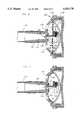
- FIG. 2is a longitudinal cross-section of a flushing valve according to a first embodiment of the invention, in its open position;
- FIG. 3shows the valve of FIG. 2 in its operative, closing position
- FIG. 4is a modified embodiment of the valve of FIGS. 2 and 3;
- FIG. 5is a sectional view taken along line V--V of FIG. 4, on an enlarged scale;
- FIG. 6is a cross-sectional view of the flushing valve according to a second embodiment of the invention, in its open position.
- FIG. 7shows the valve of FIG. 6 in its closing position.
- FIG. 1there is schematically shown a typical irrigation line 10, provided with a series of distanced stick-in drip-emitters 12 of any known type.
- flushing valve 14To the free end of the line 10 there is mounted flushing valve 14, generally comprising a two-parts housing 16 comprising an upstream portion 16a and a downstream portion 16b.
- the housing 16is mounted to the line by an inlet portion 16c, possibly fastened by a clamp or band 17.
- the housing 16comprising the portions 16a and 16b and attachment inlet portion 16c , is of a generally cylindrical configuration, made of plastics.
- Housing portion 16bis threadably mounted to the portion 16a (and 16c ) as shown.
- a dish-like member 18having a concave portion 20, a projecting rim or lip 21 and a cylindrical portion 22.
- the member 18loosely fits into the interior of portion 16a, and secured when the cover-like portion 16b is screwed-on to the portion 16a.
- a circular, flexible membrane 24, with a central passage in form of an orifice 26is clamped by the lip 21 and thus suspended within the housing 16.
- the housing inlet portion 16cis sleeve-like, denoted 28, adapted to be simply inserted into the free end of the irrigation line 10 (see FIG. 1). It further comprises a restricted flow passage or throat portion 30, extended by tubular portion 31 which terminates with a budging lip 32.
- One or more discharge openings 34are formed at the wall of upstream housing portion 16a, being substantially larger than the orifice 26, for a purpose that will be now explained.
- the duration of the flushing stageis governed by the elasticity of the membrane 24, the cross-section of the orifice 26 and the amount of impact applied by the nozzle-like restriction portion 30. These parameters can be easily adjusted to conform various desired operational conditions.
- the needle 36is provided with one or more elongated recesses 38 extending therealong, at least at the region of the membrane displacement from the open into the closing positions thereof.
- the recess 38thus replaces the function of the orifice 26.
- drip-emitter units of this typecomprise a torpedo-shaped head 142 at their inlet side, and a mushroom like head 144, containing a labyrinth passage thereinside at its other end, which are communicated by a bore 146, formed through a stem 147.
- the emitter 140is affixed to the wall 120 while its stem 147 is passed through opening 148 made in the membrane 124.
- the head 146loosely fits into the downstream end 131 of the sleeve 128 (which, in this case, need not be provided with a nozzle portion (30 in FIG. 2)).
- valve 114Operation of the valve 114 according to this embodiment is analogous to that of the preceding embodiment as is clearly seen in FIG. 7. Hence, again a pressure difference between compartment S1 and compartment S2 is gradually developed resulting in the closure of the membrane 124 against the budging lip 132, and thereafter against the discharge opening(s) 134.
- valve provided according to the teachings of the present inventionis most simple in construction and maintenance and therefore superior over the prior art equivalent devices.
Landscapes
- Engineering & Computer Science (AREA)
- General Engineering & Computer Science (AREA)
- Water Supply & Treatment (AREA)
- Life Sciences & Earth Sciences (AREA)
- Environmental Sciences (AREA)
- Mechanical Engineering (AREA)
- Nozzles (AREA)
- Infusion, Injection, And Reservoir Apparatuses (AREA)
- Catching Or Destruction (AREA)
- Lift Valve (AREA)
Abstract
Description
Claims (14)
Applications Claiming Priority (2)
| Application Number | Priority Date | Filing Date | Title |
|---|---|---|---|
| IL107444 | 1993-10-29 | ||
| IL10744493AIL107444A (en) | 1993-10-29 | 1993-10-29 | Drip irrigation line flushing valve |
Publications (1)
| Publication Number | Publication Date |
|---|---|
| US5535778Atrue US5535778A (en) | 1996-07-16 |
Family
ID=11065388
Family Applications (1)
| Application Number | Title | Priority Date | Filing Date |
|---|---|---|---|
| US08/328,889Expired - LifetimeUS5535778A (en) | 1993-10-29 | 1994-10-25 | Drip irrigation lines flushing valve |
Country Status (8)
| Country | Link |
|---|---|
| US (1) | US5535778A (en) |
| EP (1) | EP0650666B1 (en) |
| AT (1) | ATE153213T1 (en) |
| AU (1) | AU674614B2 (en) |
| DE (1) | DE69403303T2 (en) |
| ES (1) | ES2105496T3 (en) |
| IL (1) | IL107444A (en) |
| ZA (1) | ZA948475B (en) |
Cited By (27)
| Publication number | Priority date | Publication date | Assignee | Title |
|---|---|---|---|---|
| US6062247A (en)* | 1998-10-19 | 2000-05-16 | King, Sr.; Lloyd Herbert | One-piece shut-off valve |
| US6962318B1 (en) | 2004-04-15 | 2005-11-08 | Nugent William P | Pulsed input shutoff valve |
| US20070194149A1 (en)* | 2006-02-22 | 2007-08-23 | Rain Bird Corporation | Drip emitter |
| US20080023078A1 (en)* | 2005-01-25 | 2008-01-31 | Aerocrine Ab | Constant Flow Regulator Device |
| US8628032B2 (en) | 2008-12-31 | 2014-01-14 | Rain Bird Corporation | Low flow irrigation emitter |
| WO2015071797A2 (en) | 2013-11-17 | 2015-05-21 | Netafim Ltd | Valve apparatus |
| US9485923B2 (en) | 2012-03-26 | 2016-11-08 | Rain Bird Corporation | Elastomeric emitter and methods relating to same |
| WO2017115263A1 (en) | 2015-12-28 | 2017-07-06 | Netafim Ltd | Irrigation system |
| US9872444B2 (en) | 2013-03-15 | 2018-01-23 | Rain Bird Corporation | Drip emitter |
| US9877440B2 (en) | 2012-03-26 | 2018-01-30 | Rain Bird Corporation | Elastomeric emitter and methods relating to same |
| US9877442B2 (en) | 2012-03-26 | 2018-01-30 | Rain Bird Corporation | Drip line and emitter and methods relating to same |
| US9883640B2 (en) | 2013-10-22 | 2018-02-06 | Rain Bird Corporation | Methods and apparatus for transporting elastomeric emitters and/or manufacturing drip lines |
| USD811179S1 (en) | 2013-08-12 | 2018-02-27 | Rain Bird Corporation | Emitter part |
| WO2018055505A1 (en)* | 2016-09-23 | 2018-03-29 | Luria Navot | Irrigation tube flushing system and flush valve therefor |
| CN108708988A (en)* | 2018-07-18 | 2018-10-26 | 中灌顺鑫华霖科技发展有限公司 | A kind of flushing valve of droping irrigating pipe end |
| US10285342B2 (en) | 2013-08-12 | 2019-05-14 | Rain Bird Corporation | Elastomeric emitter and methods relating to same |
| US10330559B2 (en) | 2014-09-11 | 2019-06-25 | Rain Bird Corporation | Methods and apparatus for checking emitter bonds in an irrigation drip line |
| US10375904B2 (en) | 2016-07-18 | 2019-08-13 | Rain Bird Corporation | Emitter locating system and related methods |
| US10440903B2 (en) | 2012-03-26 | 2019-10-15 | Rain Bird Corporation | Drip line emitter and methods relating to same |
| CN110701354A (en)* | 2019-11-12 | 2020-01-17 | 植艺坚 | A fast pulse type air pressure switch control valve device |
| US10626998B2 (en) | 2017-05-15 | 2020-04-21 | Rain Bird Corporation | Drip emitter with check valve |
| US10631473B2 (en) | 2013-08-12 | 2020-04-28 | Rain Bird Corporation | Elastomeric emitter and methods relating to same |
| USD883048S1 (en) | 2017-12-12 | 2020-05-05 | Rain Bird Corporation | Emitter part |
| US11051466B2 (en) | 2017-01-27 | 2021-07-06 | Rain Bird Corporation | Pressure compensation members, emitters, drip line and methods relating to same |
| US11337384B2 (en)* | 2017-07-20 | 2022-05-24 | Netafim, Ltd. | Irrigation system and method for controlling liquid flow in adjacent field zones |
| US11985924B2 (en) | 2018-06-11 | 2024-05-21 | Rain Bird Corporation | Emitter outlet, emitter, drip line and methods relating to same |
| US12207599B2 (en) | 2021-10-12 | 2025-01-28 | Rain Bird Corporation | Emitter coupler and irrigation system |
Families Citing this family (8)
| Publication number | Priority date | Publication date | Assignee | Title |
|---|---|---|---|---|
| US5813603A (en)* | 1996-02-16 | 1998-09-29 | Vernay Laboratories, Inc. | Low throughput water system flow control members and methods of inhibiting swelling of such members |
| CN1083546C (en)* | 1998-12-21 | 2002-04-24 | 刘影棠 | Time-delay valve for gasbag |
| US8758333B2 (en) | 2006-04-04 | 2014-06-24 | The Spectranetics Corporation | Laser-assisted guidewire having a variable stiffness shaft |
| US9421065B2 (en) | 2008-04-02 | 2016-08-23 | The Spectranetics Corporation | Liquid light-guide catheter with optically diverging tip |
| US8979828B2 (en) | 2008-07-21 | 2015-03-17 | The Spectranetics Corporation | Tapered liquid light guide |
| EP2696929A1 (en) | 2011-04-11 | 2014-02-19 | The Spectranetics Corporation | Needle and guidewire holder |
| WO2012141747A2 (en) | 2011-04-11 | 2012-10-18 | Upstream Peripheral Technologies | Hypotube based support catheter |
| CN111173957B (en)* | 2020-02-28 | 2025-01-24 | 中国水利水电科学研究院 | Flush valve and drip irrigation device |
Citations (4)
| Publication number | Priority date | Publication date | Assignee | Title |
|---|---|---|---|---|
| US1768305A (en)* | 1928-07-05 | 1930-06-24 | Grady Tingle J | Water cut-off |
| US3138174A (en)* | 1961-11-13 | 1964-06-23 | William V Gilpin | Automatic excess fluid flow valve |
| US4022244A (en)* | 1973-12-14 | 1977-05-10 | Oman William S | Irrigation purge valve |
| IL60774A (en)* | 1980-08-06 | 1983-05-15 | Hydro Plan Eng | Irrigation system flushing valve |
Family Cites Families (2)
| Publication number | Priority date | Publication date | Assignee | Title |
|---|---|---|---|---|
| US3921905A (en)* | 1974-11-11 | 1975-11-25 | Hawaiian Sugar Planters & 0 As | Soil irrigation methods and apparatus |
| US4121621A (en)* | 1976-12-02 | 1978-10-24 | Reed Irrigation Systems | Pilot operated flushing valve |
- 1993
- 1993-10-29ILIL10744493Apatent/IL107444A/ennot_activeIP Right Cessation
- 1994
- 1994-10-25USUS08/328,889patent/US5535778A/ennot_activeExpired - Lifetime
- 1994-10-26ATAT94203108Tpatent/ATE153213T1/ennot_activeIP Right Cessation
- 1994-10-26EPEP19940203108patent/EP0650666B1/ennot_activeExpired - Lifetime
- 1994-10-26ESES94203108Tpatent/ES2105496T3/ennot_activeExpired - Lifetime
- 1994-10-26DEDE69403303Tpatent/DE69403303T2/ennot_activeExpired - Lifetime
- 1994-10-27ZAZA948475Apatent/ZA948475B/enunknown
- 1994-10-31AUAU77535/94Apatent/AU674614B2/ennot_activeExpired
Patent Citations (5)
| Publication number | Priority date | Publication date | Assignee | Title |
|---|---|---|---|---|
| US1768305A (en)* | 1928-07-05 | 1930-06-24 | Grady Tingle J | Water cut-off |
| US3138174A (en)* | 1961-11-13 | 1964-06-23 | William V Gilpin | Automatic excess fluid flow valve |
| US4022244A (en)* | 1973-12-14 | 1977-05-10 | Oman William S | Irrigation purge valve |
| IL60774A (en)* | 1980-08-06 | 1983-05-15 | Hydro Plan Eng | Irrigation system flushing valve |
| US4427174A (en)* | 1980-08-06 | 1984-01-24 | Hydro-Plan Engineering Ltd. | Irrigation system flushing valve |
Cited By (46)
| Publication number | Priority date | Publication date | Assignee | Title |
|---|---|---|---|---|
| US6062247A (en)* | 1998-10-19 | 2000-05-16 | King, Sr.; Lloyd Herbert | One-piece shut-off valve |
| US6962318B1 (en) | 2004-04-15 | 2005-11-08 | Nugent William P | Pulsed input shutoff valve |
| US20080023078A1 (en)* | 2005-01-25 | 2008-01-31 | Aerocrine Ab | Constant Flow Regulator Device |
| JP2008529155A (en)* | 2005-01-25 | 2008-07-31 | アエロクライン・アクチボラゲット | Constant flow regulator mechanism |
| JP2012185847A (en)* | 2005-01-25 | 2012-09-27 | Aerocrine Ab | Constant flow regulator mechanism |
| US20070194149A1 (en)* | 2006-02-22 | 2007-08-23 | Rain Bird Corporation | Drip emitter |
| US7648085B2 (en) | 2006-02-22 | 2010-01-19 | Rain Bird Corporation | Drip emitter |
| US10842090B2 (en) | 2006-02-22 | 2020-11-24 | Rain Bird Corporation | Drip emitter |
| US9743595B2 (en) | 2006-02-22 | 2017-08-29 | Rain Bird Corporation | Drip emitter |
| US8628032B2 (en) | 2008-12-31 | 2014-01-14 | Rain Bird Corporation | Low flow irrigation emitter |
| US9877440B2 (en) | 2012-03-26 | 2018-01-30 | Rain Bird Corporation | Elastomeric emitter and methods relating to same |
| US9485923B2 (en) | 2012-03-26 | 2016-11-08 | Rain Bird Corporation | Elastomeric emitter and methods relating to same |
| US11185021B2 (en) | 2012-03-26 | 2021-11-30 | Rain Bird Corporation | Elastomeric emitter and methods relating to same |
| US10440903B2 (en) | 2012-03-26 | 2019-10-15 | Rain Bird Corporation | Drip line emitter and methods relating to same |
| US9877441B2 (en) | 2012-03-26 | 2018-01-30 | Rain Bird Corporation | Elastomeric emitter and methods relating to same |
| US9877442B2 (en) | 2012-03-26 | 2018-01-30 | Rain Bird Corporation | Drip line and emitter and methods relating to same |
| US9872444B2 (en) | 2013-03-15 | 2018-01-23 | Rain Bird Corporation | Drip emitter |
| USD826662S1 (en) | 2013-08-12 | 2018-08-28 | Rain Bird Corporation | Emitter inlet |
| USD811179S1 (en) | 2013-08-12 | 2018-02-27 | Rain Bird Corporation | Emitter part |
| US10285342B2 (en) | 2013-08-12 | 2019-05-14 | Rain Bird Corporation | Elastomeric emitter and methods relating to same |
| US10631473B2 (en) | 2013-08-12 | 2020-04-28 | Rain Bird Corporation | Elastomeric emitter and methods relating to same |
| US9883640B2 (en) | 2013-10-22 | 2018-02-06 | Rain Bird Corporation | Methods and apparatus for transporting elastomeric emitters and/or manufacturing drip lines |
| US10420293B2 (en) | 2013-10-22 | 2019-09-24 | Rain Bird Corporation | Methods and apparatus for transporting emitters and/or manufacturing drip line |
| WO2015071797A2 (en) | 2013-11-17 | 2015-05-21 | Netafim Ltd | Valve apparatus |
| WO2015071797A3 (en)* | 2013-11-17 | 2015-10-29 | Netafim Ltd | Valve apparatus |
| US10420294B2 (en) | 2013-11-17 | 2019-09-24 | Netafim, Ltd. | Valve apparatus |
| US12174091B2 (en) | 2014-09-11 | 2024-12-24 | Rain Bird Corporation | Methods and apparatus for checking emitter bonds in an irrigation drip line |
| US10330559B2 (en) | 2014-09-11 | 2019-06-25 | Rain Bird Corporation | Methods and apparatus for checking emitter bonds in an irrigation drip line |
| US11422055B2 (en) | 2014-09-11 | 2022-08-23 | Rain Bird Corporation | Methods and apparatus for checking emitter bonds in an irrigation drip line |
| WO2017115263A1 (en) | 2015-12-28 | 2017-07-06 | Netafim Ltd | Irrigation system |
| US10588275B2 (en) | 2015-12-28 | 2020-03-17 | Netafim, Ltd. | Irrigation system |
| US10750684B2 (en) | 2016-07-18 | 2020-08-25 | Rain Bird Corporation | Emitter locating system and related methods |
| US10375904B2 (en) | 2016-07-18 | 2019-08-13 | Rain Bird Corporation | Emitter locating system and related methods |
| WO2018055505A1 (en)* | 2016-09-23 | 2018-03-29 | Luria Navot | Irrigation tube flushing system and flush valve therefor |
| US12041889B2 (en) | 2017-01-27 | 2024-07-23 | Rain Bird Corporation | Pressure compensation members, emitters, drip line and methods relating to same |
| US11051466B2 (en) | 2017-01-27 | 2021-07-06 | Rain Bird Corporation | Pressure compensation members, emitters, drip line and methods relating to same |
| US10626998B2 (en) | 2017-05-15 | 2020-04-21 | Rain Bird Corporation | Drip emitter with check valve |
| US11337384B2 (en)* | 2017-07-20 | 2022-05-24 | Netafim, Ltd. | Irrigation system and method for controlling liquid flow in adjacent field zones |
| USD883048S1 (en) | 2017-12-12 | 2020-05-05 | Rain Bird Corporation | Emitter part |
| USD978637S1 (en) | 2017-12-12 | 2023-02-21 | Rain Bird Corporation | Emitter part |
| US12342766B2 (en) | 2018-06-11 | 2025-07-01 | Rain Bird Corporation | Emitter outlet, emitter, drip line and methods relating to same |
| US11985924B2 (en) | 2018-06-11 | 2024-05-21 | Rain Bird Corporation | Emitter outlet, emitter, drip line and methods relating to same |
| CN108708988A (en)* | 2018-07-18 | 2018-10-26 | 中灌顺鑫华霖科技发展有限公司 | A kind of flushing valve of droping irrigating pipe end |
| CN108708988B (en)* | 2018-07-18 | 2024-04-23 | 中灌顺鑫华霖科技发展有限公司 | Drip irrigation pipeline end flushing valve |
| CN110701354A (en)* | 2019-11-12 | 2020-01-17 | 植艺坚 | A fast pulse type air pressure switch control valve device |
| US12207599B2 (en) | 2021-10-12 | 2025-01-28 | Rain Bird Corporation | Emitter coupler and irrigation system |
Also Published As
| Publication number | Publication date |
|---|---|
| AU674614B2 (en) | 1997-01-02 |
| ATE153213T1 (en) | 1997-06-15 |
| ES2105496T3 (en) | 1997-10-16 |
| AU7753594A (en) | 1995-05-18 |
| DE69403303D1 (en) | 1997-06-26 |
| IL107444A (en) | 1999-03-12 |
| DE69403303T2 (en) | 1998-02-26 |
| EP0650666A1 (en) | 1995-05-03 |
| ZA948475B (en) | 1996-02-05 |
| IL107444A0 (en) | 1994-01-25 |
| EP0650666B1 (en) | 1997-05-21 |
Similar Documents
| Publication | Publication Date | Title |
|---|---|---|
| US5535778A (en) | Drip irrigation lines flushing valve | |
| US4687143A (en) | Drip irrigation apparatus | |
| US4424936A (en) | Drip-irrigation emitter for mounting on a liquid supply-conduit | |
| US4502631A (en) | Trickle irrigation unit | |
| US5829686A (en) | Irrigation emitters having reduced sensitivity to clogging | |
| HUT68353A (en) | Regulated drip irrigation emitter | |
| US3288371A (en) | Spray shower assembly with self-cleaning nozzle | |
| CN107638965B (en) | Shower jet generating device | |
| CA2400135A1 (en) | Bypass orifice and filter for diaphragm type flush valve | |
| SU1648289A1 (en) | Dripper | |
| AU744070B2 (en) | An improved irrigation sprinkler | |
| US3602244A (en) | Valve assembly | |
| KR970006197B1 (en) | Flow restrictor | |
| US4966328A (en) | Microsprayers for use in irrigation | |
| US4364519A (en) | Nozzle assembly for low pressure impact sprinkler | |
| SU1109091A1 (en) | Drip feed | |
| US386256A (en) | Tumbler-washer | |
| KR0140038Y1 (en) | Irrigation Hose for Mulching Vinyl | |
| SU1628967A1 (en) | Irrigation installation | |
| SU1142061A1 (en) | Dropper | |
| JPS5946005B2 (en) | flow control device | |
| SU854327A1 (en) | Dropping tube | |
| SU1021431A1 (en) | Outlet standpipe | |
| KR950019331A (en) | Pilot valve | |
| US6176253B1 (en) | Device for introducing substances into water |
Legal Events
| Date | Code | Title | Description |
|---|---|---|---|
| STCF | Information on status: patent grant | Free format text:PATENTED CASE | |
| AS | Assignment | Owner name:ARAN ENGENEERING DEVELOPMENT LTD., A CORP OF ISREA Free format text:ASSIGNMENT OF ASSIGNORS INTEREST;ASSIGNOR:ZAKAI, ABI;REEL/FRAME:008178/0521 Effective date:19960926 Owner name:NETAFIM YIFTACH IRRIGATION AND DRIP SYSTEMS, A CO Free format text:ASSIGNMENT OF ASSIGNORS INTEREST;ASSIGNOR:ZAKAI, ABI;REEL/FRAME:008178/0521 Effective date:19960926 Owner name:NETAFIM IRRIGATION EQUIPMENT AND DRIP SYSTEMS IN K Free format text:ASSIGNMENT OF ASSIGNORS INTEREST;ASSIGNOR:ZAKAI, ABI;REEL/FRAME:008178/0521 Effective date:19960926 Owner name:NETAFIM MAGAL, A CORP OF ISRAEL, ISRAEL Free format text:ASSIGNMENT OF ASSIGNORS INTEREST;ASSIGNOR:ZAKAI, ABI;REEL/FRAME:008178/0521 Effective date:19960926 | |
| FEPP | Fee payment procedure | Free format text:PAYOR NUMBER ASSIGNED (ORIGINAL EVENT CODE: ASPN); ENTITY STATUS OF PATENT OWNER: SMALL ENTITY | |
| FPAY | Fee payment | Year of fee payment:4 | |
| REMI | Maintenance fee reminder mailed | ||
| FPAY | Fee payment | Year of fee payment:8 | |
| SULP | Surcharge for late payment | Year of fee payment:7 | |
| AS | Assignment | Owner name:NETAFIM LTD., ISRAEL Free format text:MERGER;ASSIGNORS:NETAFIM IRRIGATION EQUIPMENT & DRIP SYSTEMS;NETAFIM MAGAL;NETAFIM YIFTACH IRRIGATION EQUIPMENT & DRIP SYSTEMS;AND OTHERS;REEL/FRAME:019872/0219 Effective date:19981231 | |
| FPAY | Fee payment | Year of fee payment:12 |