US5535274A - Universal connection for cellular telephone interface - Google Patents
Universal connection for cellular telephone interfaceDownload PDFInfo
- Publication number
- US5535274A US5535274AUS08/229,956US22995694AUS5535274AUS 5535274 AUS5535274 AUS 5535274AUS 22995694 AUS22995694 AUS 22995694AUS 5535274 AUS5535274 AUS 5535274A
- Authority
- US
- United States
- Prior art keywords
- cellular telephone
- connector
- pocket device
- common
- Prior art date
- Legal status (The legal status is an assumption and is not a legal conclusion. Google has not performed a legal analysis and makes no representation as to the accuracy of the status listed.)
- Expired - Lifetime
Links
Images


Classifications
- H—ELECTRICITY
- H04—ELECTRIC COMMUNICATION TECHNIQUE
- H04M—TELEPHONIC COMMUNICATION
- H04M1/00—Substation equipment, e.g. for use by subscribers
- H04M1/738—Interface circuits for coupling substations to external telephone lines
- H—ELECTRICITY
- H02—GENERATION; CONVERSION OR DISTRIBUTION OF ELECTRIC POWER
- H02J—CIRCUIT ARRANGEMENTS OR SYSTEMS FOR SUPPLYING OR DISTRIBUTING ELECTRIC POWER; SYSTEMS FOR STORING ELECTRIC ENERGY
- H02J7/00—Circuit arrangements for charging or depolarising batteries or for supplying loads from batteries
- H02J7/00047—Circuit arrangements for charging or depolarising batteries or for supplying loads from batteries with provisions for charging different types of batteries
- H—ELECTRICITY
- H01—ELECTRIC ELEMENTS
- H01R—ELECTRICALLY-CONDUCTIVE CONNECTIONS; STRUCTURAL ASSOCIATIONS OF A PLURALITY OF MUTUALLY-INSULATED ELECTRICAL CONNECTING ELEMENTS; COUPLING DEVICES; CURRENT COLLECTORS
- H01R31/00—Coupling parts supported only by co-operation with counterpart
- H01R31/06—Intermediate parts for linking two coupling parts, e.g. adapter
- H—ELECTRICITY
- H02—GENERATION; CONVERSION OR DISTRIBUTION OF ELECTRIC POWER
- H02J—CIRCUIT ARRANGEMENTS OR SYSTEMS FOR SUPPLYING OR DISTRIBUTING ELECTRIC POWER; SYSTEMS FOR STORING ELECTRIC ENERGY
- H02J7/00—Circuit arrangements for charging or depolarising batteries or for supplying loads from batteries
- H02J7/00032—Circuit arrangements for charging or depolarising batteries or for supplying loads from batteries characterised by data exchange
- H02J7/00036—Charger exchanging data with battery
- H—ELECTRICITY
- H02—GENERATION; CONVERSION OR DISTRIBUTION OF ELECTRIC POWER
- H02J—CIRCUIT ARRANGEMENTS OR SYSTEMS FOR SUPPLYING OR DISTRIBUTING ELECTRIC POWER; SYSTEMS FOR STORING ELECTRIC ENERGY
- H02J7/00—Circuit arrangements for charging or depolarising batteries or for supplying loads from batteries
- H02J7/0042—Circuit arrangements for charging or depolarising batteries or for supplying loads from batteries characterised by the mechanical construction
- H02J7/0044—Circuit arrangements for charging or depolarising batteries or for supplying loads from batteries characterised by the mechanical construction specially adapted for holding portable devices containing batteries
- H—ELECTRICITY
- H02—GENERATION; CONVERSION OR DISTRIBUTION OF ELECTRIC POWER
- H02J—CIRCUIT ARRANGEMENTS OR SYSTEMS FOR SUPPLYING OR DISTRIBUTING ELECTRIC POWER; SYSTEMS FOR STORING ELECTRIC ENERGY
- H02J7/00—Circuit arrangements for charging or depolarising batteries or for supplying loads from batteries
- H02J7/0042—Circuit arrangements for charging or depolarising batteries or for supplying loads from batteries characterised by the mechanical construction
- H02J7/0045—Circuit arrangements for charging or depolarising batteries or for supplying loads from batteries characterised by the mechanical construction concerning the insertion or the connection of the batteries
- H—ELECTRICITY
- H04—ELECTRIC COMMUNICATION TECHNIQUE
- H04B—TRANSMISSION
- H04B1/00—Details of transmission systems, not covered by a single one of groups H04B3/00 - H04B13/00; Details of transmission systems not characterised by the medium used for transmission
- H04B1/38—Transceivers, i.e. devices in which transmitter and receiver form a structural unit and in which at least one part is used for functions of transmitting and receiving
- H04B1/3816—Mechanical arrangements for accommodating identification devices, e.g. cards or chips; with connectors for programming identification devices
- H—ELECTRICITY
- H04—ELECTRIC COMMUNICATION TECHNIQUE
- H04B—TRANSMISSION
- H04B1/00—Details of transmission systems, not covered by a single one of groups H04B3/00 - H04B13/00; Details of transmission systems not characterised by the medium used for transmission
- H04B1/38—Transceivers, i.e. devices in which transmitter and receiver form a structural unit and in which at least one part is used for functions of transmitting and receiving
- H04B1/3827—Portable transceivers
- H04B1/385—Transceivers carried on the body, e.g. in helmets
- H—ELECTRICITY
- H04—ELECTRIC COMMUNICATION TECHNIQUE
- H04B—TRANSMISSION
- H04B1/00—Details of transmission systems, not covered by a single one of groups H04B3/00 - H04B13/00; Details of transmission systems not characterised by the medium used for transmission
- H04B1/38—Transceivers, i.e. devices in which transmitter and receiver form a structural unit and in which at least one part is used for functions of transmitting and receiving
- H04B1/3827—Portable transceivers
- H04B1/3877—Arrangements for enabling portable transceivers to be used in a fixed position, e.g. cradles or boosters
- H—ELECTRICITY
- H04—ELECTRIC COMMUNICATION TECHNIQUE
- H04B—TRANSMISSION
- H04B1/00—Details of transmission systems, not covered by a single one of groups H04B3/00 - H04B13/00; Details of transmission systems not characterised by the medium used for transmission
- H04B1/38—Transceivers, i.e. devices in which transmitter and receiver form a structural unit and in which at least one part is used for functions of transmitting and receiving
- H04B1/3827—Portable transceivers
- H04B1/3883—Arrangements for mounting batteries or battery chargers
- H—ELECTRICITY
- H04—ELECTRIC COMMUNICATION TECHNIQUE
- H04M—TELEPHONIC COMMUNICATION
- H04M1/00—Substation equipment, e.g. for use by subscribers
- H04M1/02—Constructional features of telephone sets
- H04M1/0202—Portable telephone sets, e.g. cordless phones, mobile phones or bar type handsets
- H04M1/0249—Details of the mechanical connection between the housing parts or relating to the method of assembly
- H—ELECTRICITY
- H04—ELECTRIC COMMUNICATION TECHNIQUE
- H04M—TELEPHONIC COMMUNICATION
- H04M1/00—Substation equipment, e.g. for use by subscribers
- H04M1/60—Substation equipment, e.g. for use by subscribers including speech amplifiers
- H04M1/6033—Substation equipment, e.g. for use by subscribers including speech amplifiers for providing handsfree use or a loudspeaker mode in telephone sets
- H04M1/6041—Portable telephones adapted for handsfree use
- H04M1/6075—Portable telephones adapted for handsfree use adapted for handsfree use in a vehicle
- H—ELECTRICITY
- H04—ELECTRIC COMMUNICATION TECHNIQUE
- H04W—WIRELESS COMMUNICATION NETWORKS
- H04W88/00—Devices specially adapted for wireless communication networks, e.g. terminals, base stations or access point devices
- H04W88/02—Terminal devices
- H—ELECTRICITY
- H01—ELECTRIC ELEMENTS
- H01R—ELECTRICALLY-CONDUCTIVE CONNECTIONS; STRUCTURAL ASSOCIATIONS OF A PLURALITY OF MUTUALLY-INSULATED ELECTRICAL CONNECTING ELEMENTS; COUPLING DEVICES; CURRENT COLLECTORS
- H01R2201/00—Connectors or connections adapted for particular applications
- H01R2201/16—Connectors or connections adapted for particular applications for telephony
Definitions
- the present inventionrelates generally to cellular telephone interfacing systems and processes. More particularly, the present invention relates to an apparatus for providing a communications interface between a cellular telephone, selected from a variety of such telephones, to a common base unit.
- kitsto provide the required features. These kits include physical hardware to retain the phone in the vehicle including an attachment for establishing an electrical connection to the phone and various types of remote speakers, microphones and antenna connections. These kits also include complex electronics modules to provide battery charging, audio amplification and digital communication interface to the phone unit.
- One object of the present inventionis to provide a universal physical and electrical connection to a plurality of different kinds of hand-held cellular telephone units.
- a selectable adapter cable codingpermits determination of the unique identity of the type of attached phone thereby allowing a data processing unit or the like to establish appropriate electrical interfacing support operations.
- a further purpose of the inventionis to provide means to interface with a large number of hand-held and portable phones to achieve low cost electrical adapters that are useful with many makes and models of phones.
- One embodiment of the present inventionprovides a universal interface with a cable having on a first end a multiple contact connector of a predetermined number of connectors in a predetermined configuration and contact assignment discipline. At least one of the first end connectors is adapted for presenting a coded signal. That coding signal identifies at least the type of cellular phone attached to the connector on the opposite end of the cable. An arrangement is coupled to the coded signal connector for determining the type of cellular phone attached to the opposite end connector of the cable. Once the phone identification is determined, the system enables the cable first end connector contacts for performing functional operations with the cellular telephone attached to the cable.
- the coded signalcorrelates to the identity of a particular type of cellular telephone.
- Information for controlling the cable first end connector for functionally operating with a particular one of a plurality of cellular telephonesis retrievably stored as a multiplicity of information groups. Each such group is selectable in accordance with the coded signal. This makes it possible to respond to a received coded signal for selecting the information group identified thereby from storage and for using that group to enable appropriate interfacing with the cellular telephone through the cable connectors.
- An apparatus for providing a universal interface with a hand held cellular telephonecan include a cable with first and second connectors.
- the first connectoris attached to one end of the cable and includes contacts for the production of battery charging power as well as for exchanging radio frequency, audio and digital signals. It can also include structure to identify the make and model of the cellular telephone independently of that telephone.
- the second connectoris attached to the opposite end of the cable. It includes contacts for allowing attachment to a predetermined one of a plurality of different types of cellular telephone units.
- the cablefurther includes a plurality of conductors which interconnect the first and second connector contacts that have common or corresponding functions.
- a second embodiment of the present inventionpreferably provides a communications interface between at least one of a plurality of cellular telephones and a common base unit for providing a number of functions associated with cellular telephones.
- This embodimentpreferably includes at least a first pocket device having a connector housing for establishing a physical and electrical connection with a cellular telephone and further having an electrical interface for establishing an electrical connection with a common base unit. Flexible electrical conductors are provided for establishing an interconnection between the connector housing and the electrical interface.
- a common connectoris connected to the electrical interface and provides a standard physical and electrical configuration for the interface.
- a communications assemblysuch as an electrically conductive cable, interconnects the common base unit and the common connector to establish a communication path therebetween.
- the first pocket devicealso preferably includes an identifier unit for providing information related to the identity of the cellular telephone to which the first pocket device is connected.
- the identifier unitpreferably includes a non-volatile ROM or other memory device for storing information and a communications port for communicating identifying information to the common base unit. Based on the identifying information, the common base unit may establish a plurality of operating parameters for use with the cellular telephone connected to the first pocket device.
- FIG. 1shows a contemporary cellular telephone and its interconnection port
- FIGS. 2A to 2Fshow examples of a variety of hand-held cellular telephone input/output physical interfaces
- FIG. 3is a tabulation of the electrical functions associated with a typical input/output connector for a contemporary cellular telephone
- FIG. 4is an exemplary embodiment of an adapter cable in accordance with a first embodiment of the present invention.
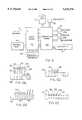
- FIG. 5is a block diagram of a typical hand-held cellular phone unit
- FIGS. 6A to 6Dillustrate one method of embodying a coded adapter cable connector in accordance with this invention
- FIG. 7is a diagram of an embodiment in accordance with this invention for identifying the adapter interface connector
- FIG. 8is a partially schematic diagram of another embodiment of this invention for identifying the adapter cable by selectable resistor means
- FIG. 9is a tabulation of an exemplary connection assignment discipline for use in conjunction with the present invention.
- FIG. 10shows a configuration of a cable connector mounting suitable for attachment to a panel, dashboard, bulkhead or the like
- FIG. 11is another configuration of a cable connector mounting suitable for a panel type attachment
- FIG. 12is an arrangement for a cable connector mounting as a replacement for a vehicle cigarette lighter
- FIG. 13is an illustration of a female connector for adapting the FIG. 4 cable as an extension
- FIG. 14is an exploded view of a universal connection system in accordance with a second embodiment of the present invention.
- FIG. 15is an exploded assembly view of a base unit in accordance with the second embodiment
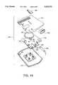
- FIG. 16is an exploded assembly view of a pocket adapter device in accordance with the second embodiment
- FIG. 17is a perspective view of the pocket adapter device illustrating the connector for connecting the cellular telephone and the pocket device;
- FIG. 18is a perspective view of the base unit and the back of a pocket device in accordance with the present invention illustrating the physical interconnection between the pocket device and the base unit;
- FIGS. 19A-19Cillustrate the manner of interconnecting the pocket device to the base unit
- FIGS. 20A-20Billustrate the manner by which the pocket device is released from the base unit
- FIG. 21is a perspective view illustrating a cellular telephone connected to the pocket device and the pocket device attached to the base unit;
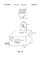
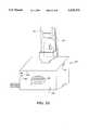
- FIG. 22is an illustration of a stationary base unit in accordance with the second embodiment of the present invention.
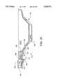
- FIG. 23is an illustration of the interconnection between a pocket device in accordance with the second embodiment of the present invention and a stationary base unit;
- FIG. 24is a frontal view of an embodiment of the retaining clip in accordance with the present invention.
- FIG. 25is an elevation view of the retaining clip, taken along line 25-25 of FIG. 24;
- FIG. 26is an elevation view illustrating the interconnection between the retaining clip illustrated in FIG. 24 and the pocket adapter of the present invention
- FIG. 27is a perspective view of a wall mountable battery charging unit for use in charging phone batteries for each different make of phone.
- FIG. 28is a perspective view of a battery charging unit for placement on a desk or other surface for use in charging phone batteries for each different make of phone;
- FIG. 29is an exploded assembly view of a pocket adapter in accordance with the present invention which is particularly adapted to connect with a Motorola Flip Phone;
- FIG. 30is a perspective view of a slidable connector housing in accordance with the embodiment of FIG. 29;
- FIG. 31is a cross-sectional view of the pocket adapter illustrated in FIG. 29 taken along a cross section Z--Z.
- the present inventionis described below with emphasis on automobile applications and environments. However, the invention is not restricted to a particular type of vehicle application, but is suited for use in any type of environment including all types of vehicles, as well as in buildings and anywhere portable communication units are operational.
- Such networksmay include analog mobile cellular telephone networks (Advanced Mobile Phone Service, or AMPS), dual-mode analog/digital mobile cellular telephone networks, purely digital mobile cellular telephone networks, or any of a range of other types of networks using cellular and other technologies.
- AMPSAdvanced Mobile Phone Service
- Other cellular-like servicesmay include personal communications services (PCs) and satellite-based mobile radio networks such as those proposed before the FCC as low-earth-orbit (LEO) systems.
- PCspersonal communications services
- LEOlow-earth-orbit
- radio systemthat these inventions pertain to include, but are not limited to, geosynchronous satellite systems such as that planned by the American Mobile Satellite Corporation and Telestat Canada, as well as conventional terrestrial mobile radio systems, Specialized Mobile Radio (SMR) systems adapted for digital data transmission, Enhanced SMR systems, and carrier-provided mobile services such as paging services, the IBM/Motorola ARDIS network, RAM Mobile Data, and any other commercial radio service.
- SMRSpecialized Mobile Radio
- Hand-held cellular telephonessuch as unit 10 illustrated in FIG. 1, employ a wide variety of physical interfaces. There are a large number of models of cellular telephones in existence and each physical interconnection and electrical interface is unique to a manufacturers specific model.
- Cellular phone 10includes a typical array of features for such devices. Keypad 12 allows dialing and other data processing/generating functions. An earphone 14 is positioned at one end while a microphone/speaker 15 is located at the other end. Liquid crystal display (LCD) 16 provides a compact presentation of limited information to the user while switch 18 is for on/off control. Antenna 19 communicates with the base unit for the phone 10 when it is removed from its holder. A battery pack 20 is attached to the lower portion of phone 10 and requires periodic recharging when unit 10 is placed in the base unit (not shown). It is released for detachment by manual button 21.
- LCDliquid crystal display
- Interconnections with the base unitare established by a plug 22 at one end of unit 10.
- the particular connector of FIG. 1is a male connection with a center extension 24 having arrays of electrical contacts on the upper and lower surfaces thereof.
- an RF coaxial type element 25is included as a portion of plug 22. Note that not every cellular telephone has an RF connector even though one is included in the example shown as element 25.
- unit 10is stored in the base unit so as to couple plug 22 with a complementary connector in the base unit.
- FIGS. 2A through 2Fshow a series of examples of presently used physical interconnections for cellular telephones. That is, FIGS. 2A to 2F present typical examples of cylindrical, rectangular, spring contact and pad type connections used in common cellular phone units, usually in the base plate thereof. From this it is apparent the wide range of configurations and physical sizes prohibits a common interconnection to a base unit or the like. Cellular phones are expected to use even smaller connectors as the units are further miniaturized in the future.
- FIG. 3A typical example of the functions assigned to the pins of a conventional phone input/output connector 22 containing connector contacts or pins 31-40 is shown in FIG. 3. Note that connector 22 of FIG. 3 might or might not represent the specific pin function assignments for connector 22 shown in FIG. 1. While there is a certain amount of commonality of functions associated with many cellular phones, the particular function assigned to a given pin often varies as does the number of functions, the number of pins and their physical configurations.
- Connector 22is shown with a coaxial connector 25 to provide for direct connection to the RF output.
- Pin 31is used for battery charging from the remote adapter, while pin 32 is used to detect the presence of the remote adapter and pin 33 is used for digital communication to the remote adapter.
- Pin 34is used to signal the remote adapter that phone power is on.
- Pin 35has the low level audio output signal to drive a remote speaker amplifier.
- Pins 36 and 39provide internal ground connections.
- Pin 37provides the CPU clock signal
- pin 38is the local to CPU communications port
- pin 40is used to receive the signal from the remote microphone.
- FIG. 5The internal architecture of a typical phone unit is shown in block diagram form in FIG. 5 where further details of the interconnections with the internal block functions of the phone with the input/output connector 22 described above are presented.
- the peripheral elements of FIG. 5correspond to their counterparts of FIG. 1.
- Radio board 42contains the radio frequency signal handling components whereas a computer including a conventional CPU with its input/output interfaces is contained in board 44.
- the CPU of board 44handles all the host functions associated with the components shown.
- the present inventionin part contemplates creation of an adapter cable with a universal interface as a common connector at one end but with that cable provided with a suitable connector at the other end to attach to a particular connector configured to another contact assignment discipline.
- the present inventionfurther contemplates the creation of a plurality of pocket adapter devices, each pocket adapter device being adapted to establish a physical and electrical interconnection between a particular model of cellular telephone and a common base unit.
- a suitable connectoris designed so that any phone unit may be accommodated regardless of electrical interface.
- a manner of identifyingis provided to determine exactly what phone unit is connected to the adapter cable so that the electronic interface can properly adapt to that phone.
- a suitable connectormust meet several conflicting requirements.
- An acceptable connector systemmust be low cost, allow a variety of mounting arrangements and have characteristics suitable for its intended operating environment such as for use not only in automobiles but also in vehicles, boats, tractors, residences, and so forth. Often the operating environment demands shielding of the cable and connector as protection against interference with other equipment that is interference signal sensitive as well as to protect the phone system from interference signals.
- Such a connector and adapter cable systemis shown in FIG. 4 and described below.
- a universal connector 45 or plugis arranged in accordance with a predetermined assignment of pin functions.
- a connector or plug 48configured to attach to a particular cellular phone such as one of those illustrated in FIGS. 2A-2F. That is, connector 48 is different for each differently configured connector on a cellular phone.
- the conductors within cable 46are connected within plugs 45 and 48 so that the pin functions are matched.
- connector 45can include an arrangement for providing a signal to the using device, host or base unit attached to plug 45 wherein the signal is encoded to identify the kind of cellular phone plugged into connector 48 at the other end of cable 46.
- FIG. 9One example of a suitable connector for providing a standard interface connection, as for the FIG. 4 cable, is illustrated in FIG. 9.
- This connectoris preferably panel mounted and consists of a protective hood 90 protecting a rectangular center block 100 of insulating material with parallel rows of contacts.
- Each rowpreferably has eight gold plated, substantially flat contacts 91-98 and 101-108. These contacts are formed slightly convex in order to create miniature leaf springs which provide pressure with the contacts of the mating connector.
- the interface to the mating connectorsis such that they are self-cleaning by means of the self wiping action during insertion. This is an especially important consideration in automobile applications.
- hood 90could provide a shield against outside signals interfering with the cable signals or, conversely, against signals in cable 46 from interfering with other equipments. This is possible by electrically connecting hood 90 to a sleeve type RF shield encasing the main body of cable 46 and a similar shielding hood at the opposite end connector 48.
- the contact pins 91-98 and 101-108are arrayed along each side of block 100 with the tubular, coaxial radio frequency (RF) connector 99 located in spaced relation towards one end.
- RFradio frequency
- a typical such connector 99is 0.10 inches in diameter with low standing wave ratio at frequencies of 800 to 900 MHz suitable for attachment to a coaxial cable. Connections to the contacts are conventional as by soldering, crimping or the like.
- the center block 100 and RF connector 99are recessed in a rectangular shell 90 to provide protection from physical damage.
- the mating connectorhas the same characteristics with the housing designed to provide protection cable strain relief and a locking mechanism to provide secure engagement but allow easy removal.
- connector 45 of FIG. 4is arranged in accordance with FIG. 9 whereas connector 48 on the opposite end of cable 46 is configured pursuant to the FIG. 3 discipline
- the conductors through cable 46would interconnect the pins at each plug which have comparable functions.
- a coaxial cablewould thus couple RF plug 25 with RF plug 99.
- Conductorswould also interconnect battery pin 31 with charger pin 101, both pins 36 and 39 with ground pin 91, clock pin 37 with pin 96, pin 35 with pin 92, and pin 40 with pin 94.
- pin 34is connected with pin 103 while pin 32 is interconnected with pin 102.
- pin 33is coupled to pin 97 while pin 38 goes to pin 95 as does pin 35.
- pins 105-108 identified as P1-P4are employed for device identification purposes as is described in detail in FIGS. 6, 7 and 8.
- the FIG. 9 connectorhas a battery temperature sensor input terminal 98. This is to accommodate cellular phones that include such a sensor output even though the FIG. 3 connector does not include this function.
- the control device attached to plug 90senses the model type identification from terminals 105-108, it would realize that the phone model involved here does not have a battery temperature sensing signal and would ignore pin 98. Otherwise the controller adjusts its interconnections and support functioning for terminals 91-98 and 101-104 to fully cooperate with the phone connected via appropriate conductors to the other end of the cable from connector 90.
- FIG. 10shows connector 120, a snap-in bulkhead mounting version, that mates with the adapter cable.
- a trim bezel 121forms a front panel mounting surface.
- molded clipssuch as 122 allow easy insertion but expand and lock against the rear surface of the panel retaining the connector body while accommodating a range of panel thickness. This and the following version are useful for original equipment automobile installation.
- Assembly 125 of FIG. 11is somewhat similar to FIG. 10 but is designed for either front or rear insertion of connector 126.
- a bezel assembly 128includes snap-mount retaining clips such as 129 to hold assembly 128 in a panel opening similar to the FIG. 10 clips as described above.
- Assembly 128acts as a receiver for connector body 126 which in this example has snap tongues such as 130 on the upper and lower surfaces which engage respective slots such as slots 131 and 132 in the bezel assembly 128.
- Rear mountingis desirable in some cases where the cable is permanently affixed to an electronics module for example. Many variations of this and the previous mounting method are possible to provide easier installation and lower product cost. For instance, it is possible to integrate the bezel with the dashboard fascia molding eliminating or modifying elements of the mounting method.
- FIG. 12illustrates a connector 110 that mates with the adapter cable.
- This versionresides in a housing 112 designed in a manner identical to the common automotive cigarette lighter assembly which is approximately 7/8 inches in diameter. It can include means to secure it to the panel such as retaining tabs 115 and a locating groove 116 especially if it is removable. Installation is accomplished by replacing the existing lighter assembly without requiring permanent modification to the vehicle. If necessary the original lighter assembly can be re-installed at some future time to restore the vehicles to its original condition. This version is useful in an aftermarket installation kit.
- FIG. 13is a mating cable end to the adapter cable used when it is desired to provide an extension cable or to allow a variety of mounting methods which may attach directly to the connector or cable body. That is, connector 75 is attached to cable 76 which corresponds to cable 46 of FIG. 4. The connector on the other end of cable 76, although not shown in FIG. 13, is the same as connector 45 of FIG. 4. Receiving female connector elements 77 and 78 are thus compatible with attachment to a male connector constructed the same as plug 45.
- One embodiment for determining the make and model of the phoneemploys a cable adapter to identify itself to the electronics module or host assembly 150. This is accomplished in the FIGS. 6A-6D configuration by a number of pins reserved at the processor or common end of the cable connector for use as a programming device.
- An electrically conductive structure 50 containing a plurality of physically and electrically interconnected pins 51-55is inserted into and retained by connector body 58 as seen in FIG. 6B.
- a short connecting link 56extends above ridge or shoulder 57 above the connector body 58 when connector 50 is inserted therein.
- These linksare preferably clipped in a binary pattern to produce the identification data for the processor 154 so that it can determine the type of cellular phone attached to the other end of the cable.
- the connector body 58includes conventional, well-known means (not shown) for retaining the end of the clipped contact in place so as to prevent it from falling out or sliding back into the connector body when the connectors are coupled.
- decode logic circuitry 66can establish a voltage at the mating connector 60 by means of a resistor network 70 connected to the digital logic supply voltage 72.
- a resistor network 70connected to the digital logic supply voltage 72.
- pin 51represents the most significant bit
- in sequence pin 54represents the least significant bit.
- the digital pattern 0001is detectable at the mating connector 60 by the decode logic 66.
- the connector 50 configurationthereby allows detection of a total of 16 different identification codes or 32 if system ground (91 or 104) is used.
- the use of additional connector pinscan substantially increase the number of available unique codes. If desired, it is possible to generate the digital or analog identification codes at the cellular phone or its connector. However, this requires circuit complexity and additional conductors through the cable which is avoided by incorporation of the code generation in the universal connector as described herein.
- a computeris part of the host assembly although hard wired control units or other combinations of electronic elements are acceptable.
- the control unit or computerstores a series of blocks of data in a memory or other data storage device with each block containing the instructions necessary for controlling the universal connector interfacing circuits to operate through the universal connector into a particular type of cellular telephone.
- the blocks of dataare each retrievable from the data storage device in accordance with the identification code presented to the computer on the universal connector.
- the controlling deviceuses the retrieved data to set up a compatible set of switches, voltage levels, signal paths, etc., at the host system universal connector interface to work with the kind of cellular telephone specified by the identification data.
- the systemlikewise is controlled to establish normal operations with the attached cellular telephone thereafter.
- the systemis ready to function whenever a cellular telephone is connected to one end of a cable with the other end attached to the host system universal connector input port.
- the decoding device in the host assemblysamples the universal connector 50 pin connections which are specified as the source of code signals for identification of the type of connector and/or telephone present on the other end of the cable.
- the processordoes this by decoding the binary identification number from those pins.
- the processoractually identifies the type of phone via a table look-up operation. Once having determined the cellular phone type, the processor next establishes the necessary interfacing voltages, signal protocols and interconnections to allow the base unit to communicate with the phone in an appropriate manner compatible with the type of phone attached.
- analog to digital (A/D) converter 80provides a reference voltage (Vref) to line 81 which is presented to the mating connector pins 82 and 83.
- the voltageproduces a current through the circuit consisting of resistor 84 (Rprog) and resistor 85 (Rfixed) in a half-bridge configuration providing a voltage at pin 87 which is connected to the signal input of A/D converter 80.
- a 6 bit A/D convertercan provide 64 possible binary codes to logic 86.
- the value for each Rprog resistor 84is calculated from the equation: Vout*Rfixed/(Vref-Vout).
- Rprogis a list of programming resistor values which uniquely determine one of the 64 possible input voltages to the D/A converter 80 which result in distinct binary output codes.
- Rfixedis the half-bridge calibrating resistor 85 and Vref is present on line 81.
- Vrefis 5.0 volts
- Rfixis 100k ohms
- “Hex”is a hexadecimal address
- the Rprog terms such as "1.43E+ 03"means, a resistive value in ohms computed by 1.43 times 10 to the third power (or 1000).
- Yet another version of the previously discussed apparatus and methodsis to use a plurality of programming resistors with one end connected in common to Vref and a like number of A/D converters. This can provide a large expansion in the number of identification bits or allow the use of less expensive A/D converters having fewer conversion bits.
- a second embodiment of the present inventionillustrated in FIGS. 14-31, includes a common base unit for mounting in an automobile.
- the base unitis able to be selectably connected to each one of a plurality of pocket adapters or devices to achieve desired communications between the cellular telephone and the common base unit.
- This embodimentallows cellular telephone users to interconnect various models of cellular telephones to the common base unit using the particular, selected pocket adapter that properly provides a communications interface between the cellular telephone and the common base unit.
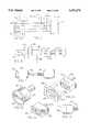
- FIG. 14is an exploded perspective view of this embodiment and illustrates a cellular telephone 200, a pocket adapter 202 for receiving a particular model of cellular telephone, a common base unit 204, and a cable 206 for providing a physical and electrical connection between the common base unit 204 and the pocket adapter 202.
- the cellular telephone 200includes a connector 208 for establishing a physical and electrical connection with an external base unit and an RF connector 210 for establishing a connection with an external antenna.
- the base unit 204may be permanently mounted in the passenger compartment of the automobile by means of a bracket 212, as illustrated in FIG. 18.
- a common base unit 204 in accordance with the present inventionmay be otherwise included in the automobile, including by means of a factory installed base unit which may be an integral part of the automobile's electrical system.
- the common base unit 204 of the disclosed embodimentis capable of operating with any available cellular telephone.
- the base unit 204includes a housing 214 having a top section 216 connectable with a bottom section 218.
- a retaining clip 220 for securing the pocket adapter 202 to the housing 214 of the base unit 204is mounted on the top section 216 of the housing 214.
- a circuit board 222is mounted to the bottom section 218 of the housing and is disposed between the top section 216 and bottom section 218 when the base unit 204 is assembled.
- the circuit board 222includes a microprocessor 224 for managing the communications interface between the cellular telephone 200 and the common base unit 204.
- the circuit board 222also includes a number of connectors for use with peripheral devices including an RJ-11 jack 226, a remote microphone jack 228, and a headset jack 230.
- a speaker 232is connected to on the circuit board for hands-free operation of the cellular phone. The speaker volume may be adjusted using volume control knob 234 also mounted on the circuit board 222.
- the base unit 204further includes a recessed cavity 236 for retaining a connector 256 when the base unit is not connected to a phone.
- An electrical cable 206 for providing a connection between the base unit 204 and the pocket adapter 202has a first end 252 securely connected to the base unit 204.
- the second end 254 of cable 206includes the base unit connector 256 that mates with electrical interface 322 of pocket adapter 202.
- the base unit connector 256is protected from damage by a shell having a top section 258 and a bottom section 260.
- the pocket adapter 202includes an upper shell 280 having a recessed surface 282 and side walls 284 for receiving cellular telephone 200.
- the recessed surface 282is shaped to correspond to the back wall of the particular model of cellular telephone for which the pocket was designed.
- the upper shell 280also includes a phone retainer latch 286 to facilitate securing the cellular telephone 200 in place within the pocket adapter 202.
- the pocket adapter 202also includes a lower shell 290 interconnectable with the upper shell 280 to define a cavity therebetween.
- a latching assembly 292 for securing the pocket adapter 202 to the retaining clip 220 of base unit 204is disposed on the back side of pocket adapter 202. Operation of the latching assembly 292 and retaining clip 220 in securing the pocket adapter 202 to the common base 204 is illustrated in FIGS. 19A-19C.
- the latching assembly 292includes a recessed groove or channel 294 for receiving the retaining clip 220.
- the retaining clip 220which is formed from plastic or other such resilient material, includes a spring member 221 which is biased outwardly from an axis A--A drawn longitudinally through the center of retaining clip 220. As illustrated in FIG.
- FIGS. 24-26An embodiment of retaining clip 220 is shown in greater detail in FIGS. 24-26.
- a vertical flange 600is part of the spring member 221 and extends from the spring member main body.
- a horizontal flange 602extends laterally from the vertical flange 600.
- FIG. 26is a cross sectional view illustrating the interconnection between retaining clip 220 and latching assembly 292 when retaining clip 220 is secured within latching assembly 292.
- horizontal flange 602cooperates with lip 604 to inhibit upward deflection of spring member 221 and vertical flange 600 cooperates with lip 606 to inhibit lateral deflection of spring member 221 in a direction away from axis A-A.
- the cooperation between horizontal flange 602 and lip 606 and vertical flange 600 and lip 606further facilitates securing retaining clip 220 within latching assembly 292.
- the latching assembly 292also includes a release mechanism 298 for releasing the pocket adapter 202 from base unit 204. Operation of the release mechanism 298 is illustrated in FIGS. 20A-20B.
- the release mechanism 298is slidably engaged with the latching assembly 292 and positioned such that the release mechanism 298 is aligned with spring member 221 when retaining clip 220 is fixed within latching assembly 292.
- the release mechanism 298is forced in the direction indicated by arrow 502 and the release mechanism 298 forces spring member 221 toward axis A--A. Once spring member 221 has cleared catch member 296, the retaining clip may be slid from the recessed groove 294, thereby removing the pocket adapter 202 from the base unit 204.
- connection assembly 318is disposed in the cavity between the upper shell 280 and the lower shell 290 of the pocket adapter 202.
- the connection assembly 318is used to electrically interconnect the cellular telephone 200 to the electrical interface 322.
- the connection assembly 318includes a connector housing 320, a connector mount 321 and a flexible cable conductor 323.
- the connector housing 320has a number of conductor contacts 325 (FIG. 17), which may be a variety of connectors, including, for example, spring contacts and fixed connectors.
- the cable conductor 323, at a first end,is disposed between the connector housing 320 and the connector mount 321.
- the cable conductor 323includes a number of conductors for providing electrical communication with the cellular telephone's connector 208 (FIG. 14).
- the electrical leads of the cable conductor 323are connected to the electrical interface 322 having a predetermined pin configuration for communication with the base unit connector of cable 206.
- the electrical interfaceincludes sixteen pin assignments, which are designated as follows:
- Conducting wires 4-7are used for various purposes depending on the particular cellular phone 200. Wires 13-16 are reserved for future digital uses, but can also be assigned as multi-purpose connections. The following identifies some typical assignments that might be made of wires 4-7:
- the connection assembly 318also includes a coupler 324 for connecting to the antenna connector on the cellular telephone. If the cellular telephone has an external RF connector, such as connector 210 on cellular telephone 200, then the coupler 324 may be directly connected to the cellular telephone antenna via connector 326 (FIG. 17). However, if the cellular telephone does not have an external RF connector, the coupler 324 may also act to absorb power or energy from the cellular telephone antenna for transmitting or relaying the same to an external antenna. The coupler 324 is also connected to predetermined pins on the electrical interface 322 to provide an electrical connection to an external antenna for use with the cellular telephone 200.
- a memory storage devicesuch as a non-volatile ROM chip 330, is provided to store information related to the particular model of cellular telephone 200 for use with the pocket device 202 including operating parameters such as the electrical characteristics and communications protocols associated with the cellular telephone 200.
- the ROM chip 330may store information regarding the voltage required to operate the cellular telephone or to charge its batteries.
- the ROM chip 330may also include information regarding the features of the cellular telephone, such as whether the telephone has a serial communications port.
- the information on the ROM chip 330may be downloaded to microprocessor 224 in base unit 204 to allow base unit 204 to establish operating parameters corresponding to those required by cellular telephone 200.
- the ROM chip 330is located between the electrical interface 322 and the connector housing 320 and within the pocket device 202.
- the ROM chip 330is positioned within the cable that interconnects the particular cellular telephone and the base unit. This embodiment is useful where no pocket device is required, such as when all of the cellular phones or radios of interest have the same configured pin assignments so that no universal connector for each of these phones is required.
- the ROM chip 330 informationis advantageously used, for example, in providing the correct battery charging voltage to the particular cellular telephone that is connected to the cable.
- connection assembly 450in accordance with the present invention and illustrated in FIGS. 29-31, is particularly adapted for interconnection with a cellular telephone 420 available from Motorola. As illustrated in FIG. 29, the connection assembly 450 is disposed between an upper shell 432 and a lower shell 434 of pocket adapter 430.
- the pocket adapter 430includes hardware for physically securing the cellular telephone within the adapter as previously described. Accordingly, the following discussion will focus on the electrical connection between the telephone and the base unit 204.
- the connection assembly 450includes an electrical interface 452 for establishing an electrical connection between the pocket adapter 430 and a common base unit 204.
- a flexible cable conductor 454is connected to the electrical interface 452 at a first end and a portion of flexible cable 454 has a plurality of telephone connector contacts 456 at a second end for providing an electrical interconnection between the telephone 420 and the electrical interface 452.
- Disposed along the length of the flexible cableis a memory IC or ROM chip 453, which is comparable to the chip 330 of FIG. 16.
- Another portion of flexible cable 454includes battery contacts 458 for establishing an electrical connection with the battery of the telephone 420 to charge the battery and an antenna coupler 460 which is able to absorb power from the cellular telephone's antenna and transmit the same to the electrical interface 452 for further transmittal to an external antenna.
- the connection assembly 450further includes a slidable connector housing 462, illustrated in perspective view in FIG. 30, having a base 464 including first and second lateral support members 466, 466'.
- a thumb-tab panel 468 having a knurled surface 470is supported by opposing panels 472,472' and 474, 474', which extend substantially perpendicularly from base 464.
- First and second strain relief posts 478, 478'are integrally molded with panels 474 and 474' to enhance the structural integrity of slidable connector housing 462.
- a cover member 476extends substantially perpendicularly from panel 472.
- the slidable connector housing 462further includes a male adapter 490 configured to mate with the electrical connector 422 of the telephone 420 and also has a plurality of retaining channels 492 for receiving the telephone connector contacts 456 of flexible cable 454.
- the upper surface of base 464includes a plurality of connector posts 480 which interconnect with opposing holes 484 on connector mount 482 to secure connector mount 482 to connector housing 462.
- a portion of first and second strain relief posts 478, 478'also extend through base 464 to provide male connectors which mate with opposing female connectors 486, 486' on connector mount 482.
- connection assembly 450 and pocket adapter 430are assembled by first securing the telephone connector contacts 456 within the retaining channels 492. Detents 455, 455' in flexible cable 454 interconnect with support posts 478,478', respectively, to retain flexible cable 454 in position on base 464.
- the connector mount 482is secured to the base 464 of the slidable connector housing 462 to fix the flexible cable connector 454 in place with respect to the slidable connector housing 462.
- the disclosed embodimentutilizes a heat-setting procedure to secure the connector mount 482 to the slidable connector housing 462, however it will be appreciated that the closure block 482 could be attached by other fasteners including clamps, bolts or screws. Securing the flexible cable 454 to the slidable connector housing in this manner reduces the possiblity of a telephone connector contact 456 coming loose from cable 454 during use.
- the slidable connector housing 462is then positioned within lower shell 434, with thumb-tab 468 protruding through hole 442 in lower shell 440 of pocket adapter 430 and with support members 466, 466' disposed within channels 444 and 444' respectively.
- the battery contact spring clips 458 and antenna loop 460are positioned on bottom shell 440 of pocket adapter 430 and the pocket adapter is assembled by ⁇ snapping ⁇ the upper shell 432 and lower shell 434 together.
- FIG. 31is a cross sectional view of the assembled pocket adapter 430 taken along lines 31-31 of FIG. 29.
- a portion of flexible cable 454is disposed along the surface of lower shell 434 to establish an electrical connection with battery contacts 458 and to provide an antenna lead 460.
- the portion of flexible cable 454 having a plurality of telephone connector contacts 456is connected to male adapter 490.
- Electrical interface 452is disposed at an end of pocket adapter 430 to facilitate interconnection with base unit connector 256 of cable 206 to establish a communications interface with a common base unit 204.
- the cellular phone 420is physically disposed within the pocket adapter 430.
- the electrical connectionis established by using the thumb-tab 468 to slide the connector housing 462 in the direction indicated by arrow 510, which moves the male adapter 490 into contact with the electrical connector 422 of the telephone 420.
- the pocket adapter 430may then be connected to a universal base unit for use in accordance with the present invention as disclosed above.
- the phone 420may then be physically removed from the pocket adapter 430.
- base unit 204may be mounted in the passenger compartment of an automobile or other such vehicle and may be connected to a power source either directly or through an adapter connected to the cigarette lighter.
- the userfirst connects a cellular telephone to the pocket adapter 202 designed for use with the telephone.
- the pocket adapteris then connected to the base unit 204 using the cord 206.
- the pocket adapter 202may be secured to the base unit 204 using retaining clip 220 and latching assembly 292 as described above.
- the power to the base unit 204is turned on, the information in the pocket adapter's ROM chip 330 is downloaded to the microprocessor 224 in the base unit 204. Based on this information, the base unit 204 establishes operating parameters which correspond to the requirements of telephone 200.
- the userneed only select a pocket adapter for use with the second cellular telephone.
- this adapteris connected to the base unit 204 and the power is turned on, the operating parameters and communications protocols for the second telephone are downloaded from the second telephone's pocket adapter to the microprocessor. Based on this information, the microprocessor 224 adjusts the operating parameters and communications protocols for operation of the second cellular telephone with the base unit 204.
- any pocket adapter in accordance with the present inventionmay be connected to any base unit in accordance with the present invention. Further, because the information is stored in memory which is remote from the base unit, the system may be expanded to include additional models of telephones without the need to reprogram additional protocols into the base unit.
- FIGS. 22-23present an embodiment of base unit 400 particularly adapted for stationary use, such as on a desktop.
- Base unit 400includes connector 402 which is configured to mate with outlet 322 of a pocket adapter 202 in accordance with the present invention.
- Base unit 400further includes a support member 410 having a retaining clip 412 positioned to connect with latching assembly 292 of pocket adapter 202 when pocket adapter 202 is connected to base unit 400.
- Support member 410facilitates securing pocket adapter 202 to base unit 400.
- a microprocessor in base unit 400configures the system for operation with the selected cellular telephone by downloading the operating parameters from the ROM chip 330 in the pocket adapter 202.
- the base unit 400may operate with different cellular telephones by simply replacing the cellular telephone and the corresponding pocket adapter.
- the stationary base unit 400performs substantially the same functions performed by the mobile base unit 204 discussed above.
- base unit 400may include a speaker 420 to facilitate hands-free operation of cellular telephone 200, an RJ-11 jack 422, a remote microphone jack 424, a headset jack 426 and a data communications port 428.
- the stationary base unit 400may also have additional communications functions, such as an answering machine, built into the base unit.
- additional communications functionssuch as an answering machine
- FIGS. 27 and 28illustrate embodiments of battery charger units for use with pocket devices in accordance with the present invention.
- the battery charger 650 of FIG. 27is particularly adapted to plug directly into an AC outlet as would be found in any home or office.
- Battery charger 650includes a cable 652 having a connector 654 that mates with electrical interface 322 of pocket adapter 202.
- Battery charger 650further includes a retaining clip 656 for interconnection with the latching assembly 292 of pocket adapter 202 to secure pocket adapter 202 to battery charger 650.
- Retaining clip 656works in substantially the same fashion as the retaining clip discussed above.
- pocket adapter 202When pocket adapter 202 is electrically connected to battery charger 650 by cable 654 a microprocessor in battery charger 650 downloads information from ROM chip 330 and establishes appropriate electrical parameters for charging cellular phone 200 in accordance with the information received from ROM chip 330 in the same fashion as discussed above. In this manner, battery charger 650 may be used to charge any cellular phone for which there is a corresponding pocket adapter.
- FIG. 28is an illustration of a battery charger 700 which is adapted to be placed on a working surface, such as a desk, counter or the like.
- the battery charger of FIG. 28includes an electrical cord 702 for plugging the charger into an outlet.
- a connector 704 that mates with electrical interface 322 of pocket adapter 202is positioned with an aperture 706 on the top surface of battery charger 700.
- a support block 708 particularly adapted to mate with a surface of pocket adapter 202may be positioned on battery charger 700, using conventional means, such as by snapping the block into preformed holes in battery charger 700, to help support pocket adapter 202.
- pocket adapter 202is connected to battery charger 700 by interconnecting connector 704 and electrical interface 322.
- a microprocessor in battery charger 700downloads information from ROM chip 330 and establishes the appropriate electrical parameters to charge cellular phone 200, as discussed above.
- the battery chargeris physically located within the cable itself that interconnects the cellular telephone or radio and a base unit. This embodiment is particularly advantageous when no pocket device 202 is required, such as when a universal connector is not necessary because all cellular phones or radios of interest have a common connector.
- the present inventionis not limited to cellular transmission of voice data but also encompasses the transmission of other data across cellular telephone networks.
- computer modems, facsimile machines, scanners, bar code readers, or other digital information processorsmay be connected to the base unit to provide for the transmission of digital data across the cellular link.
- the pocket adapter of the present inventioncan also include an infrared (IR) receiver for use with telephones having an IR transmitter. The IR receiver is able to properly handle the IR signal from the telephone including the intelligence that is part of the IR signal.
- IRinfrared
Landscapes
- Engineering & Computer Science (AREA)
- Signal Processing (AREA)
- Computer Networks & Wireless Communication (AREA)
- Power Engineering (AREA)
- Telephone Set Structure (AREA)
- Mobile Radio Communication Systems (AREA)
- Telephonic Communication Services (AREA)
- Charge And Discharge Circuits For Batteries Or The Like (AREA)
- Communication Control (AREA)
Abstract
Description
______________________________________ Pin Wire Designation ______________________________________ 1 Phone Power Supply 2 Battery Charge 3 DC/Digital common 4 I/O 1 Serial data from phone/Control Option 5 I/O 2 Serial data to phone/Control Option 6 I/O 3 Control Option 7 I/O 4 Control Option 8 ROM Data 9ROM Clock 10 Audio signal from phone (RX) 11 Audio signal to phone (TX) 12 Audio common 13 Reserved 14Reserved 15Reserved 16 Reserved ______________________________________
__________________________________________________________________________Wire Phone 1 Phone 2 Phone 3 Phone 4 Phone 5 __________________________________________________________________________4 Hang.sub.-- upSerial 1 Serial 1 HFVA.sub.-- exist Serial 1 5 Speaker.sub.-- Mute Serial 2 Serial 2 HFVA.sub.-- sw Serial 2 6 Ign.sub.-- Sense Serial 3 Clock Audio.sub.-- enable Clock 7 Pwr.sub.-- status HFVA.sub.-- exist Pwr.sub.-- status __________________________________________________________________________
TABLE I ______________________________________ APPENDIX For Vref 5 and Rfix 100000 Step Hex Rprog Vout ______________________________________ 1 0 1.43E+03 0.070 2 1 2.89E+03 0.141 3 2 4.40E+03 0.211 4 3 5.96E+03 0.281 5 4 7.56E+03 0.352 6 5 9.22E+03 0.422 7 6 1.09E+04 0.492 8 7 1.27E+04 0.563 9 8 1.45E+04 0.633 10 9 1.64E+04 0.703 11 A 1.83E+04 0.773 12 B 2.03E+04 0.844 13 C 2.24E+04 0.914 14 D 2.45E+04 0.984 15 E 2.67E+04 1.055 16 F 2.90E+04 1.125 17 10 3.14E+04 1.195 18 11 3.39E+04 1.266 19 12 3.65E+04 1.336 20 13 3.91E+04 1.406 21 14 4.19E+04 1.477 22 15 4.48E+04 1.547 23 16 4.78E+04 1.617 24 17 5.09E+04 1.688 25 18 5.42E+04 1.758 26 19 5.76E+04 1.828 27 1A 6.12E+04 1.898 28 1B 6.49E+04 1.969 29 1C 6.89E+04 2.039 30 1D 7.30E+04 2.109 31 1E 7.73E+04 2.180 32 1F 8.18E+04 2.250 33 20 8.66E+04 2.320 34 21 9.16E+04 2.391 35 22 9.69E+04 2.461 36 23 1.03E+05 2.531 37 24 1.08E+05 2.602 38 25 1.15E+05 2.672 39 26 1.21E+05 2.742 40 27 1.29E+05 2.813 41 28 1.36E+05 2.883 42 29 1.44E+05 2.953 43 2A 1.53E+05 3.023 44 2B 1.62E+05 3.094 45 2C 1.72E+05 3.164 46 2D 1.83E+05 3.234 47 2E 1.95E+05 3.305 48 2F 2.08E+05 3.375 49 30 2.22E+05 3.445 50 31 2.37E+05 3.516 51 32 2.54E+05 3.586 52 33 2.72E+05 3.656 53 34 2.93E+05 3.727 54 35 3.16E+05 3.797 55 36 3.41E+05 3.867 56 37 3.71E+05 3.938 57 38 4.04E+05 4.008 58 39 4.42E+05 4.078 59 3A 4.87E+05 4.148 60 3B 5.40E+05 4.219 61 3C 6.03E+05 4.289 62 3D 6.80E+05 4.359 63 3E 7.77E+05 4.430 64 3F 9.00E+05 4.500 ______________________________________
Claims (19)
Priority Applications (9)
| Application Number | Priority Date | Filing Date | Title |
|---|---|---|---|
| US08/229,956US5535274A (en) | 1991-10-19 | 1994-04-19 | Universal connection for cellular telephone interface |
| DE69532471TDE69532471T2 (en) | 1994-04-19 | 1995-04-14 | UNIVERSAL CONNECTION FOR A CELLULAR TELEPHONE INTERFACE |
| EP95917567AEP0760188B1 (en) | 1994-04-19 | 1995-04-14 | Universal connection for cellular telephone interface |
| CA002186946ACA2186946A1 (en) | 1994-04-19 | 1995-04-14 | Universal connection for cellular telephone interface |
| PCT/US1995/004672WO1995028789A1 (en) | 1994-04-19 | 1995-04-14 | Universal connection for cellular telephone interface |
| JP7527134AJPH09512153A (en) | 1994-04-19 | 1995-04-14 | Universal connection for cellular telephone interface |
| ES95917567TES2214499T3 (en) | 1994-04-19 | 1995-04-14 | UNIVERSAL UNION FOR CELL PHONE INTERFACES. |
| AU23568/95AAU703245B2 (en) | 1994-04-19 | 1995-04-14 | Universal connection for cellular telephone interface |
| US08/627,472US5822427A (en) | 1991-10-19 | 1996-04-04 | Battery charging for a plurality of different cellular telephone |
Applications Claiming Priority (2)
| Application Number | Priority Date | Filing Date | Title |
|---|---|---|---|
| US07/773,840US5333177A (en) | 1991-10-19 | 1991-10-19 | Universal connection for cellular telephone interface |
| US08/229,956US5535274A (en) | 1991-10-19 | 1994-04-19 | Universal connection for cellular telephone interface |
Related Parent Applications (1)
| Application Number | Title | Priority Date | Filing Date |
|---|---|---|---|
| US07/773,840Continuation-In-PartUS5333177A (en) | 1991-10-19 | 1991-10-19 | Universal connection for cellular telephone interface |
Related Child Applications (1)
| Application Number | Title | Priority Date | Filing Date |
|---|---|---|---|
| US08/627,472DivisionUS5822427A (en) | 1991-10-19 | 1996-04-04 | Battery charging for a plurality of different cellular telephone |
Publications (1)
| Publication Number | Publication Date |
|---|---|
| US5535274Atrue US5535274A (en) | 1996-07-09 |
Family
ID=22863380
Family Applications (2)
| Application Number | Title | Priority Date | Filing Date |
|---|---|---|---|
| US08/229,956Expired - LifetimeUS5535274A (en) | 1991-10-19 | 1994-04-19 | Universal connection for cellular telephone interface |
| US08/627,472Expired - Fee RelatedUS5822427A (en) | 1991-10-19 | 1996-04-04 | Battery charging for a plurality of different cellular telephone |
Family Applications After (1)
| Application Number | Title | Priority Date | Filing Date |
|---|---|---|---|
| US08/627,472Expired - Fee RelatedUS5822427A (en) | 1991-10-19 | 1996-04-04 | Battery charging for a plurality of different cellular telephone |
Country Status (8)
| Country | Link |
|---|---|
| US (2) | US5535274A (en) |
| EP (1) | EP0760188B1 (en) |
| JP (1) | JPH09512153A (en) |
| AU (1) | AU703245B2 (en) |
| CA (1) | CA2186946A1 (en) |
| DE (1) | DE69532471T2 (en) |
| ES (1) | ES2214499T3 (en) |
| WO (1) | WO1995028789A1 (en) |
Cited By (179)
| Publication number | Priority date | Publication date | Assignee | Title |
|---|---|---|---|---|
| USD390848S (en) | 1996-06-20 | 1998-02-17 | Motorola, Inc. | Supplemental feature module for a telephone handset |
| USD392646S (en) | 1996-08-27 | 1998-03-24 | Kokusai Electric Co., Ltd. | Holder for portable wireless car telephone |
| EP0861008A1 (en)* | 1997-02-25 | 1998-08-26 | Koninklijke Philips Electronics N.V. | Telecommunications apparatus with a device for recognizing peripherals |
| USD399848S (en) | 1996-02-23 | 1998-10-20 | Nokia Mobile Phones Limited | Mount for multicommunicator |
| USD400209S (en) | 1996-10-10 | 1998-10-27 | Motorola, Inc. | Holder |
| USD404397S (en) | 1998-01-13 | 1999-01-19 | Motorola, Inc. | Hang up cup for a portable communication device |
| US5870615A (en)* | 1995-01-09 | 1999-02-09 | Intel Corporation | Automatic cellular phone battery charging by mobile personal computer using configuration write data and storage element for charging in accordance to battery charging parameter |
| USD406848S (en)* | 1997-09-03 | 1999-03-16 | Nokia Mobile Phones Limited | Accessory module for a mobile telephone |
| USD407708S (en) | 1997-06-17 | 1999-04-06 | Motorola, Inc. | Accessory housing |
| USD412910S (en) | 1996-09-16 | 1999-08-17 | Andreas Peiker | Cell phone receptor |
| USD417224S (en) | 1999-03-17 | 1999-11-30 | Motorola, Inc. | Hang-up cup |
| USD419160S (en)* | 1998-05-14 | 2000-01-18 | Northrop Grumman Corporation | Personal communications unit docking station |
| US6018672A (en)* | 1996-05-07 | 2000-01-25 | Alcatel Alsthom Compagnie Generale D'electricite | Arrangement for operating a mobile terminal in a wireless switching system based on different communication standards |
| USD425077S (en) | 1999-06-21 | 2000-05-16 | T & M Antennas | Cellular handset vehicular adapter |
| USD425908S (en)* | 1999-07-21 | 2000-05-30 | Ericsson Inc. | Hands free cradle for telephone |
| US6075976A (en)* | 1997-09-12 | 2000-06-13 | Lucent Technologies, Inc. | Communication apparatus comprising two units and means for supporting one unit on the other |
| US6084963A (en)* | 1996-11-01 | 2000-07-04 | Harness System Technologies Research, Ltd. | Phone holder for selectively holding a mobile phone |
| USD428002S (en)* | 1999-01-26 | 2000-07-11 | Telefonaktiebolaget Lm Ericsson | Handsfree cradle for telephone |
| USD432528S (en)* | 2000-02-07 | 2000-10-24 | Motorola, Inc. | Speakerphone accessory |
| USD432530S (en)* | 1999-01-26 | 2000-10-24 | Telefonaktiebolaget Lm Ericsson | Handsfree cradle for telephone |
| USD437315S1 (en) | 2000-05-17 | 2001-02-06 | Ericsson Inc. | Communication device cradle |
| USD439245S1 (en) | 1999-09-09 | 2001-03-20 | Qualcomm Incorporated | Cradle for a cellular telephone |
| US6227505B1 (en) | 1998-04-10 | 2001-05-08 | Prince Corporation | Adjustable accessory mount |
| US6230029B1 (en) | 1998-01-07 | 2001-05-08 | Advanced Mobile Solutions, Inc. | Modular wireless headset system |
| WO2001041484A1 (en) | 1999-12-06 | 2001-06-07 | Cellport Systems, Inc. | Supporting and connecting a portable phone |
| US6263268B1 (en) | 1997-08-26 | 2001-07-17 | Transcontech Corporation | System and method for providing mobile automotive telemetry |
| USD445781S1 (en) | 1999-10-26 | 2001-07-31 | Andreas Peiker | Telephone handset for a mobile phone including a support |
| US6275683B1 (en)* | 1998-01-12 | 2001-08-14 | Ericsson Inc. | Interchangeable shield for a radio communication device |
| US6290543B1 (en) | 1996-12-19 | 2001-09-18 | Lawrence L. Plummer, Jr. | Telephone adaptor |
| FR2806863A1 (en)* | 2000-03-23 | 2001-09-28 | Sanyo Electric Co | PORTABLE ELECTRICAL APPARATUS CONTAINING A BATTERY |
| US20010044331A1 (en)* | 2000-03-29 | 2001-11-22 | Hideki Miyoshi | Cellular phone in which memory is removably installable due to the removability of battery, and battery recharger capable of supporting date write to cellular phone memory |
| USD451911S1 (en) | 2000-11-21 | 2001-12-11 | Novatel Wireless, Inc. | RF wireless modem |
| USD452496S1 (en) | 2001-03-23 | 2001-12-25 | Sierra Wireless, Inc. | Wireless communication device for a personal data assistant |
| USD452495S1 (en) | 2001-02-08 | 2001-12-25 | Sierra Wireless, Inc. | Wireless communication device for a personal data assistant |
| US20020003874A1 (en)* | 1995-06-23 | 2002-01-10 | Andreas Peiker | Telephone assembly with handset having a transmitting and/or receiving component |
| US20020013140A1 (en)* | 1998-04-24 | 2002-01-31 | Fujitsu Limited | Telephone set identifying method, telephone set type identifying apparatus, processing apparatus and storage medium |
| USD454340S1 (en) | 2001-01-06 | 2002-03-12 | Safco Corporation | Phone connector assembly |
| US20020032042A1 (en)* | 2000-02-18 | 2002-03-14 | Poplawsky Ralph C. | Exporting controls to an external device connected to a portable phone system |
| USD454864S1 (en) | 2001-02-23 | 2002-03-26 | Novatel Wireless, Inc. | Wireless modem |
| USD455418S1 (en) | 2001-03-07 | 2002-04-09 | Hello Direct, Inc. | Base for a headset |
| US6377825B1 (en) | 2000-02-18 | 2002-04-23 | Cellport Systems, Inc. | Hands-free wireless communication in a vehicle |
| WO2002063790A1 (en)* | 2001-02-07 | 2002-08-15 | Michael Davis | Communications interface device |
| US6449579B1 (en)* | 1999-02-04 | 2002-09-10 | Dell Usa, L.P. | Computer chassis identification method |
| US20020171394A1 (en)* | 2000-07-03 | 2002-11-21 | Stephane Bohbot | Battery charger, in particular for a portable telephone |
| US20020197911A1 (en)* | 2001-06-25 | 2002-12-26 | Holmes David William James | System and method for providing an adapter module |
| US6509659B1 (en)* | 2001-10-24 | 2003-01-21 | Motorola, Inc. | Cable or module identification apparatus and method |
| US20030036407A1 (en)* | 2001-08-20 | 2003-02-20 | Vikram Kapoor | Cellular telephone and multimedia accessory audio system adaptor and methods therefor |
| US6526287B1 (en)* | 2000-03-22 | 2003-02-25 | Gtran Korea Inc | Cellular phone capable of accommodating electronic device |
| US20030062873A1 (en)* | 2001-10-03 | 2003-04-03 | Hsin Liao Sheng | Fast combinational charger |
| US20030076951A1 (en)* | 1995-08-11 | 2003-04-24 | Masashi Tomura | Adapter for portable telephone usable as mobile telephone in vehicle |
| US6570987B1 (en)* | 1995-06-30 | 2003-05-27 | Nokia Mobile Phones Ltd. | Telephone and its holder |
| AU761999B2 (en)* | 2001-05-03 | 2003-06-12 | E-Lead Electronic Co., Ltd | Replaceable signal cable making a sound-controlled or externally dialed hand-free system universally compatible with all types of cellular phones |
| EP0822693A3 (en)* | 1996-08-03 | 2003-07-09 | Henryk Dipl.-Ing. Bury | Hands-free equipment for telephones in motor vehicles |
| US6597924B1 (en)* | 1996-02-20 | 2003-07-22 | Texas Instruments Incorporated | Coupled portable telephone/interface module |
| USD479228S1 (en) | 2002-09-03 | 2003-09-02 | Airbiquity Inc. | Hands-free kit for mounting a wireless device in a vehicle |
| USD479523S1 (en) | 2000-12-16 | 2003-09-09 | Andreas Peiker | Mobile telephone support |
| US20030190018A1 (en)* | 2002-04-03 | 2003-10-09 | Bleile Leonard George | Apparatus, method, media and signals for controlling a wireless communication appliance |
| USD481033S1 (en) | 2001-12-21 | 2003-10-21 | Andreas Peiker | Two-part cradle for mobile phone |
| US6636749B2 (en) | 2001-06-25 | 2003-10-21 | At&T Wireless Services, Inc. | Method and apparatus for providing power and wireless protocol capability to a wireless device, such as a wireless phone |
| WO2002057117A3 (en)* | 2001-01-18 | 2003-12-18 | Andreas Peiker | Arrangement for handling a communication device |
| US6687516B2 (en)* | 1998-10-08 | 2004-02-03 | E-Lead Electronic Co., Ltd. | Hand-free receiver signal wire for mobile telephone |
| US6687513B1 (en)* | 2002-10-30 | 2004-02-03 | Hsiu-Chu Hsu Li | Device for attaching portable phones to vehicle |
| US20040033786A1 (en)* | 2001-10-23 | 2004-02-19 | Bellsouth Intellectual Property Corporation | Apparatus for providing a gateway between a wired telephone and a wireless telephone network |
| USD487453S1 (en) | 2002-02-05 | 2004-03-09 | Motorola, Inc. | Housing accessory for communication devices or similar articles |
| US20040048511A1 (en)* | 2002-03-01 | 2004-03-11 | Tal Dayan | Wirefree mobile device power supply method & system with free positioning |
| US20040082369A1 (en)* | 2002-03-01 | 2004-04-29 | Tal Dayan | Alternative wirefree mobile device power supply method & system with free positioning |
| US20040087335A1 (en)* | 2001-01-18 | 2004-05-06 | Andreas Peiker | Arrangement for handling a communication device |
| US20040110545A1 (en)* | 1997-04-25 | 2004-06-10 | Kim Ki Il | Mobile entertainment and communication device |
| US20040157612A1 (en)* | 1997-04-25 | 2004-08-12 | Minerva Industries, Inc. | Mobile communication and stethoscope system |
| US6785531B2 (en) | 2001-03-22 | 2004-08-31 | Visteon Global Technologies, Inc. | Dual-function removable reversable unit for radio and telephone |
| US6796844B1 (en) | 2003-02-07 | 2004-09-28 | Cisco Technology, Inc. | System and method for coupling a plurality of cables to a device |
| US20040192338A1 (en)* | 2002-08-26 | 2004-09-30 | Bellsouth Intellectual Property Corporation | Fixed wireless telephone device |
| WO2004086735A1 (en)* | 2003-03-24 | 2004-10-07 | Johnson Controls Technology Company | System and method for configuring a wireless communication system in a vehicle |
| US20040215111A1 (en)* | 2003-04-23 | 2004-10-28 | Bonutti Peter M. | Patient monitoring apparatus and method for orthosis and other devices |
| US20040235535A1 (en)* | 2003-05-20 | 2004-11-25 | Matsushita Electric Industrial Co., Ltd. | Communication system and communication apparatus |
| US6836644B2 (en) | 2002-08-26 | 2004-12-28 | Bellsouth Intellectual Property Corporation | Methods and apparatus for establishing a fixed wireless telephone service |
| US6842633B1 (en)* | 1999-12-21 | 2005-01-11 | Nokia Mobile Phones Ltd. | Clip arrangement for portable electronic apparatus housing assembly |
| US20050030252A1 (en)* | 2003-08-07 | 2005-02-10 | Wen-Yu Peng | [universal antenna adapter] |
| WO2005025256A1 (en) | 2003-09-08 | 2005-03-17 | Nokia Corporation | Automotive mobile terminal connection system providing mobile terminal function to enable dynamic external user interface |
| US20050064835A1 (en)* | 2003-09-18 | 2005-03-24 | International Business Machines Corporation | Audio system responsive to incoming phone calls |
| US6892051B2 (en) | 2001-06-25 | 2005-05-10 | Cingular Wireless Ii, Llc | System and method for providing an adapter module |
| US20050134544A1 (en)* | 2003-04-30 | 2005-06-23 | Kazuaki Igarashi | Display device array substrate and display device |
| US20050153749A1 (en)* | 2004-01-14 | 2005-07-14 | Microsoft Corporation | Mobile device interface and adaptation system |
| US20050202854A1 (en)* | 2004-03-12 | 2005-09-15 | Sbc Knowledge Ventures, L.P. | Universal mobile phone adapter method and system for vehicles |
| US20050233774A1 (en)* | 2004-04-16 | 2005-10-20 | Research In Motion Limited | Portable alerter for wireless device |
| US20050245272A1 (en)* | 2004-04-29 | 2005-11-03 | Spaur Charles W | Enabling interoperability between distributed devices using different communication link technologies |
| US20060030291A1 (en)* | 2004-08-05 | 2006-02-09 | International Business Machines Corporation | Traffic shaping of cellular service consumption through modification of consumer behavior encouraged by cell-based pricing advantages |
| US20060040641A1 (en)* | 2004-08-05 | 2006-02-23 | International Business Machines Corporation | Traffic shaping of cellular service consumption through delaying of service completion according to geographical-based pricing advantages |
| US7015596B2 (en) | 2003-07-03 | 2006-03-21 | Opher Pail | Electronic device display system and method |
| US7020488B1 (en) | 2000-07-19 | 2006-03-28 | Embedded Systems Products Inc. | Communications unit, system and methods for providing multiple access to a wireless transceiver |
| US20060089186A1 (en)* | 2004-10-26 | 2006-04-27 | Harald Richter | Modular apparatus holder with multipurpose intermediate support member for supporting minicomputers, cell phones and similar apparatus |
| US20060105808A1 (en)* | 2001-09-20 | 2006-05-18 | Peter Warren | Input-output device with universal phone port |
| US20060145039A1 (en)* | 2004-11-24 | 2006-07-06 | Shawver Michael J | Universal modular docking platform for portable device |
| USD532004S1 (en)* | 2004-09-08 | 2006-11-14 | Nokia Corporation | Holder for a handset |
| US20060277555A1 (en)* | 2005-06-03 | 2006-12-07 | Damian Howard | Portable device interfacing |
| US20070142097A1 (en)* | 2002-10-21 | 2007-06-21 | Shogo Hamasaki | Mounting device for mobile information terminal, and mobile information terminal |
| WO2007111516A1 (en)* | 2006-03-27 | 2007-10-04 | Mitac International Corp. | Modular electronic device mounting system |
| US20070244614A1 (en)* | 1997-08-26 | 2007-10-18 | Paxgrid Telemetric Systems, Inc. | Automotive telemetry protocol |
| US7346374B2 (en) | 1999-05-26 | 2008-03-18 | Johnson Controls Technology Company | Wireless communications system and method |
| US7349722B2 (en) | 1999-05-26 | 2008-03-25 | Johnson Controls Technology Company | Wireless communications system and method |
| US20080091575A1 (en)* | 1998-04-01 | 2008-04-17 | R & L Carriers, Inc. | Bill of Lading Transmission and Processing System for Less Than a Load Carriers |
| US7366892B2 (en) | 2003-01-28 | 2008-04-29 | Cellport Systems, Inc. | Secure telematics |
| US20080215240A1 (en)* | 2006-12-18 | 2008-09-04 | Damian Howard | Integrating User Interfaces |
| US20080304213A1 (en)* | 2003-06-24 | 2008-12-11 | Nokia Corporation | Process for manufacturing a cover |
| US20090022095A1 (en)* | 2007-07-16 | 2009-01-22 | Cellport Systems, Inc. | Communication Channel Selection and Use |
| US20090045924A1 (en)* | 2007-07-23 | 2009-02-19 | R & L Carriers, Inc. | Information Transmission and Processing Systems and Methods For Freight Carriers |
| US20090082957A1 (en)* | 2007-09-20 | 2009-03-26 | Shai Agassi | Electric Vehicle Network |
| US20090130884A1 (en)* | 2007-11-15 | 2009-05-21 | Bose Corporation | Portable device interfacing |
| US20100094496A1 (en)* | 2008-09-19 | 2010-04-15 | Barak Hershkovitz | System and Method for Operating an Electric Vehicle |
| US20100141206A1 (en)* | 2008-09-19 | 2010-06-10 | Shai Agassi | Battery Exchange Station |
| US20100164291A1 (en)* | 2008-12-26 | 2010-07-01 | Pichkur Yaroslav A | System, socket and plug apparatus for DC power distribution and usage |
| US20100176945A1 (en)* | 2009-01-14 | 2010-07-15 | Invue Security Products Inc. | Detachable carriage for merchandise security system |
| US20100323546A1 (en)* | 2009-06-19 | 2010-12-23 | Applied Optical Systems, Inc. | Rugged registered jack connection |
| US20110065305A1 (en)* | 2009-09-14 | 2011-03-17 | Gad Amit | An electrical connector with a flexible blade-shaped housing with a handle with an opening |
| US7955285B2 (en) | 1998-06-01 | 2011-06-07 | Bonutti Research Inc. | Shoulder orthosis |
| US20110140657A1 (en)* | 2010-07-12 | 2011-06-16 | Eran Genzel | Staged Deployment for Electrical Charge Spots |
| US7983034B1 (en)* | 2008-09-19 | 2011-07-19 | Victor Mohoney | Docking system for MP3 players and other portable electronic devices |
| US7981067B2 (en) | 2004-03-08 | 2011-07-19 | Bonutti Research Inc. | Range of motion device |
| US20110192857A1 (en)* | 2008-12-18 | 2011-08-11 | Wayne Philip Rothbaum | Magnetically Attached Accessories (For A Case) for a Portable Electronics Device |
| US8012108B2 (en) | 2005-08-12 | 2011-09-06 | Bonutti Research, Inc. | Range of motion system and method |
| US20110230087A1 (en)* | 2009-08-03 | 2011-09-22 | George Stantchev | Connector retainer shell |
| US20110231546A1 (en)* | 1997-08-26 | 2011-09-22 | Nathanson Martin D | Automotive telemetry protocol |
| US8038637B2 (en) | 2000-09-18 | 2011-10-18 | Bonutti Research, Inc. | Finger orthosis |
| US8062241B2 (en) | 2000-12-15 | 2011-11-22 | Bonutti Research Inc | Myofascial strap |
| US8066656B2 (en) | 2005-10-28 | 2011-11-29 | Bonutti Research, Inc. | Range of motion device |
| US8118147B2 (en) | 2009-09-11 | 2012-02-21 | Better Place GmbH | Cable dispensing system |
| US8200214B2 (en) | 2006-10-11 | 2012-06-12 | Johnson Controls Technology Company | Wireless network selection |
| US20120170736A1 (en)* | 2010-12-30 | 2012-07-05 | Hon Hai Precision Industry Co., Ltd. | Wireless telephone having support with built-in antenna |
| US8251934B2 (en) | 2000-12-01 | 2012-08-28 | Bonutti Research, Inc. | Orthosis and method for cervical mobilization |
| US8273043B2 (en) | 2007-07-25 | 2012-09-25 | Bonutti Research, Inc. | Orthosis apparatus and method of using an orthosis apparatus |
| US8319373B2 (en) | 2008-12-26 | 2012-11-27 | Pichkur Yaroslav A | System, socket and plug apparatus for DC power distribution and usage |
| US8454377B2 (en) | 2008-09-19 | 2013-06-04 | Better Place GmbH | System for electrically connecting batteries to electric vehicles |
| US20130223003A1 (en)* | 2012-02-23 | 2013-08-29 | Jeffrey D. Carnevali | Universal adaptor mount for a docking station |
| US20130224977A1 (en)* | 2012-02-23 | 2013-08-29 | Jeffrey D. Carnevali | Universal adaptor mount for a docking station |
| US8558414B2 (en) | 2010-08-11 | 2013-10-15 | Invue Security Products Inc. | Voltage regulator for merchandise display security device |
| US8666464B2 (en) | 2012-03-26 | 2014-03-04 | General Motors Llc | Vehicle interior component for supporting a communication system |
| US20140125283A1 (en)* | 2012-11-02 | 2014-05-08 | Wistron Corporation | Charging device applied to a portable mobile communication device |
| US8794579B2 (en) | 2005-06-03 | 2014-08-05 | Steelcase, Inc. | Support arm assembly |
| US8834202B2 (en) | 2011-06-13 | 2014-09-16 | Lear Corporation | Connector assembly for vehicle charging |
| US8905950B2 (en) | 2008-03-04 | 2014-12-09 | Bonutti Research, Inc. | Shoulder ROM orthosis |
| US8920346B2 (en) | 2007-02-05 | 2014-12-30 | Bonutti Research Inc. | Knee orthosis |
| US20150032607A1 (en)* | 2005-06-30 | 2015-01-29 | Innova Electronics, Inc. | Mobile device based vehicle diagnostic system |
| US20150244126A1 (en)* | 2014-02-24 | 2015-08-27 | Jeffrey D. Carnevali | Docking sleeve with electrical adapter |
| WO2015066106A3 (en)* | 2013-10-30 | 2015-11-05 | Invue Security Products Inc. | Flexible circuit for providing power to a portable electronic device |
| US20160065702A1 (en)* | 2014-02-24 | 2016-03-03 | National Products, Inc. | Docking sleeve with electrical adapter |
| US9402759B2 (en) | 2013-02-05 | 2016-08-02 | Bonutti Research, Inc. | Cervical traction systems and method |
| US9529387B2 (en) | 2014-02-24 | 2016-12-27 | National Products, Inc. | Docking sleeve with electrical adapter |
| US9602639B2 (en) | 2014-02-24 | 2017-03-21 | National Products, Inc. | Docking sleeve with electrical adapter |
| US9632535B2 (en) | 2014-02-24 | 2017-04-25 | National Products, Inc. | Docking sleeve with electrical adapter |
| US9769551B2 (en) | 2014-12-31 | 2017-09-19 | Skullcandy, Inc. | Method of connecting cable to headphone, and headphone formed using such methods |
| US9793642B2 (en) | 2011-08-22 | 2017-10-17 | Lear Corporation | Connector assembly |
| US9831904B1 (en) | 2016-12-14 | 2017-11-28 | National Products, Inc. | Adjustable cradle for mobile devices and methods of making and using |
| US20170353591A1 (en)* | 2016-06-06 | 2017-12-07 | Jeffery Rudes | Smartphone Charger |
| CN107810461A (en)* | 2015-06-29 | 2018-03-16 | 国家产品股份有限公司 | Head containing electrical interconnecting to female connector |
| TWI629582B (en)* | 2015-06-29 | 2018-07-11 | 全國產品公司 | Butt sleeve with electrical adapter |
| US10050658B2 (en) | 2014-02-24 | 2018-08-14 | National Products, Inc. | Docking sleeve with electrical adapter |
| US20180287652A1 (en)* | 2017-02-16 | 2018-10-04 | Datron World Communications, Inc. | Detachment mechanism and indicator for mobile mount portable radio |
| US10119512B2 (en)* | 2017-02-24 | 2018-11-06 | Lg Electronics Inc. | Mobile terminal and method for controlling the same |
| TWI642341B (en)* | 2014-02-24 | 2018-11-21 | 全國產品公司 | Butt sleeve with electrical adapter |
| US10187767B2 (en) | 2016-07-01 | 2019-01-22 | Paxgrid Cdn Inc. | System for authenticating and authorizing access to and accounting for wireless access vehicular environment consumption by client devices |
| US10401905B2 (en) | 2016-06-27 | 2019-09-03 | National Products, Inc. | Slide dock and methods of making and using |
| US10770853B1 (en)* | 2020-01-13 | 2020-09-08 | Pioneer Square Brands, Inc. | Electrical power coupler for portable electronic computing device and for case for portable electronic computing device |
| US10812643B1 (en) | 2020-05-04 | 2020-10-20 | National Products, Inc. | Cases for mobile devices incorporating a light within the case and methods of making and using |
| US11029731B1 (en) | 2020-04-20 | 2021-06-08 | National Products, Inc. | Cradles and cases for mobile devices incorporating guide elements or modular components and methods of making and using |
| US11076032B1 (en) | 2020-05-26 | 2021-07-27 | National Products, Inc. | Cradles for mobile devices with a plunger lock and methods of making and using |
| US11277506B2 (en) | 2020-05-26 | 2022-03-15 | National Products, Inc. | Cradles for mobile devices with one or more biasing tabs and methods of making and using |
| US11289864B2 (en) | 2020-04-20 | 2022-03-29 | National Products, Inc. | Cases for mobile devices with a flexible covering and rigid frame or with two different connector arrangements and methods of making and using |
| US11489350B2 (en) | 2019-12-23 | 2022-11-01 | National Products, Inc. | Cradle for mobile devices with resilient guides and methods of making and using |
| US11574510B2 (en) | 2020-03-30 | 2023-02-07 | Innova Electronics Corporation | Multi-functional automotive diagnostic tablet with interchangeable function-specific cartridges |
| US11626686B2 (en) | 2021-06-14 | 2023-04-11 | Havis, Inc. | Tablet docking station |
| US11651628B2 (en) | 2020-04-20 | 2023-05-16 | Innova Electronics Corporation | Router for vehicle diagnostic system |
| US11652326B2 (en) | 2021-04-30 | 2023-05-16 | National Products, Inc. | Dock with flexible locator pins and methods of making and using |
| US11728846B1 (en) | 2022-10-13 | 2023-08-15 | National Products, Inc. | Remote repeater device for mobile device dock and methods of making and using |
| US11967189B2 (en) | 2020-04-20 | 2024-04-23 | Innova Electronics Corporation | Router for communicating vehicle data to a vehicle resource |
| US12126199B2 (en) | 2021-08-09 | 2024-10-22 | National Products, Inc. | Cradles for a mobile device including a cavity for a wireless device and methods of making and using |
| EP4350932A4 (en)* | 2021-05-28 | 2024-11-13 | Globe (Jiangsu) Co., Ltd. | CHARGING DEVICE AND APPLICATION THEREOF |
| US12158776B2 (en) | 2022-04-25 | 2024-12-03 | National Products, Inc. | Docks for mobile devices with simultaneous data transfer and charging and systems and methods using the docks |
| US12298809B2 (en) | 2023-07-05 | 2025-05-13 | National Products, Inc. | Heating module for electronic device dock and methods of making and using |
| US12362527B2 (en) | 2020-06-10 | 2025-07-15 | National Products, Inc. | Cases for mobile devices incorporating a cord extending from the case and methods of making and using |
Families Citing this family (70)
| Publication number | Priority date | Publication date | Assignee | Title |
|---|---|---|---|---|
| US6212401B1 (en)* | 1996-12-24 | 2001-04-03 | Intermec Corporation | Data acquisition using telephone connection |
| US8466795B2 (en) | 1997-01-21 | 2013-06-18 | Pragmatus Mobile LLC | Personal security and tracking system |
| WO1998058454A2 (en)* | 1997-06-16 | 1998-12-23 | Dansk Mobiltelefon A/S | A docking station |
| GB2328830B (en)* | 1997-08-29 | 2002-01-09 | Nokia Mobile Phones Ltd | A handset holder |
| US6208733B1 (en)* | 1998-09-02 | 2001-03-27 | Qualcom Incorporated | Programmable hands free telephone system |
| US6725061B1 (en)* | 1999-01-12 | 2004-04-20 | Qualcomm, Incorporated | System and method for the automatic identification of accessories coupled to a wireless communication device |
| KR100694414B1 (en)* | 1999-12-30 | 2007-03-12 | 엘지전자 주식회사 | Mobile communication terminal |
| IT1316289B1 (en)* | 2000-01-21 | 2003-04-10 | Paolina Rizzi | UNIVERSAL MOBILE PHONE KIT FOR MOBILE PHONE |
| GB2360902A (en)* | 2000-03-31 | 2001-10-03 | Orange Personal Comm Serv Ltd | Dual position portable support for mobile device |
| EP1291999B1 (en)* | 2000-04-13 | 2013-01-30 | Makita Corporation | Adapter for battery charger |
| US7259539B2 (en)* | 2000-04-14 | 2007-08-21 | Zip Charge Corporation | Method and apparatus for charging a rechargeable battery |
| USD458219S1 (en) | 2000-04-24 | 2002-06-04 | Motorola, Inc. | Adapter for a radio communication device |
| US6782099B1 (en)* | 2000-06-10 | 2004-08-24 | Motorola, Inc. | Speaker-phone base for a portable telephone |
| USD460065S1 (en) | 2000-09-25 | 2002-07-09 | Sharper Image Corporation | Recorder for a cellular telephone |
| FR2818078A1 (en)* | 2000-12-08 | 2002-06-14 | Quentin Julien Romain Pavy | Mobile/portable telephone wall support having two recipients wall held using fixing holes and recharging portable server plug connection hole. |
| WO2002058408A2 (en) | 2001-01-18 | 2002-07-25 | Peiker, Andreas | Assembly comprising a mobile telephone |
| DE10103608A1 (en)* | 2001-01-28 | 2002-08-14 | Audioton Kabelwerk Gmbh | Hands-free system for operating cell phones in motor vehicles |
| DE10103609A1 (en)* | 2001-01-28 | 2002-08-14 | Audioton Kabelwerk Gmbh | Hands-free system for operating cell phones in motor vehicles |
| DE10103610A1 (en)* | 2001-01-28 | 2002-08-14 | Audioton Kabelwerk Gmbh | Hands-free system for operating cell phones in motor vehicles |
| JP3671855B2 (en)* | 2001-03-02 | 2005-07-13 | 秀 島▲ざき▼ | Mobile phone |
| USD462677S1 (en) | 2001-03-16 | 2002-09-10 | Nokia Mobile Phones Ltd. | Car holder for a handset |
| USD470136S1 (en) | 2001-03-21 | 2003-02-11 | Telefonaktiebolaget Lm Ericsson | Desk stand |
| DE10128323B4 (en)* | 2001-06-12 | 2012-05-24 | Andreas Peiker | Holder for a mobile phone in the motor vehicle |
| DE10139480B4 (en)* | 2001-06-12 | 2011-12-29 | Andreas Peiker | Holder for a mobile phone in the motor vehicle |
| DE10134655A1 (en)* | 2001-07-20 | 2003-02-06 | Gisela Bisplinghoff | Connection unit for a hands-free device |
| DE10136659B4 (en)* | 2001-07-27 | 2004-05-13 | Siemens Ag | Recording device for a mobile electronic terminal |
| WO2003019803A1 (en)* | 2001-08-23 | 2003-03-06 | Andreas Peiker | Holder for an electronic device |
| US6934561B2 (en) | 2001-09-24 | 2005-08-23 | Motorola, Inc. | Cable or module identification apparatus and method |
| TW538585B (en)* | 2001-10-30 | 2003-06-21 | Primax Electronics Ltd | Power adapting device applied in portable electronic device |
| DE10204887A1 (en)* | 2002-02-06 | 2003-09-04 | Siemens Ag | Holding device for an electronic device |
| USD484874S1 (en) | 2002-03-13 | 2004-01-06 | Incase Design Llc | Phone case |
| NL1020317C2 (en)* | 2002-04-05 | 2003-10-07 | Reinier Wouter Jacques Schram | Charging adapter for charging a rechargeable battery in a mobile phone. |
| US20030232530A1 (en)* | 2002-06-14 | 2003-12-18 | Astec International Limited | Modular power assemblies for electronic devices |
| US7254424B1 (en) | 2003-04-15 | 2007-08-07 | Reichert William E | Mobile telephone station |
| US20040235533A1 (en)* | 2003-05-21 | 2004-11-25 | Bae Hyon S. | Hands-free cradle and kit |
| DE10331412A1 (en)* | 2003-07-10 | 2005-01-27 | Bayerische Motoren Werke Ag | Holder for a mobile phone |
| JP4049112B2 (en)* | 2004-03-09 | 2008-02-20 | 株式会社日立製作所 | Electronic equipment |
| US6994592B1 (en) | 2004-08-27 | 2006-02-07 | Hop-On Wireless, Inc. | Universal charging apparatus |
| CA2519606A1 (en)* | 2004-09-15 | 2006-03-15 | Belkin Corporation | Power supply system comprising rechargeable battery pack and attachment apparatus |
| DE102004062178B4 (en) | 2004-12-21 | 2007-10-11 | Bury Sp.Z.O.O | Telephone system with a holding device for receiving a mobile phone |
| USD533175S1 (en)* | 2005-07-23 | 2006-12-05 | Harald Richter | Instrument holder |
| AT502552B1 (en)* | 2005-10-11 | 2007-07-15 | Fronius Int Gmbh | ASSEMBLY METHOD, COUPLING DEVICE AND COUPLING ELEMENT FOR A HIGH-PERFORMANCE CONTACT, AND BATTERY CHARGER WITH A CLUTCH DEVICE |
| NO324195B1 (en)* | 2005-12-09 | 2007-09-03 | Modulprodukter As | Universal mobile phone console |
| DE102006021464A1 (en)* | 2006-05-09 | 2007-11-15 | Bayerische Motoren Werke Ag | A method for testing the compatibility of a control unit of a motor vehicle handsfree with a mobile phone and vehicle |
| US7438602B2 (en)* | 2006-07-18 | 2008-10-21 | Deere & Company | Ruggedized USB port |
| US20080102765A1 (en)* | 2006-10-29 | 2008-05-01 | Sony Ericsson Mobile Communications Ab | Wireless Adaptor Power Control |
| GB2443669B (en)* | 2006-11-07 | 2011-04-13 | Bury Sp Zoo | A mounting kit for attaching a mobile phone within a mechanical vehicle |
| CN101657337B (en)† | 2007-01-29 | 2011-10-05 | 派卡阿库斯蒂克公司 | Receiving device |
| US20080182442A1 (en)* | 2007-01-31 | 2008-07-31 | Jaeho Choi | Data Port for a Mobile Device |
| US7667433B1 (en) | 2007-03-23 | 2010-02-23 | Smith Steven D | Recharging cover system |
| US7744231B2 (en)* | 2007-10-01 | 2010-06-29 | Hon Hai Precision Ind. Co., Ltd. | Electrical connector with illumination waveguide |
| ATE454732T1 (en)* | 2007-11-13 | 2010-01-15 | Tyco Electronics Belgium Ec Nv | SHIELDED USB PLUG SYSTEM |
| DE102007061483A1 (en)* | 2007-12-20 | 2009-07-02 | Erbe Elektromedizin Gmbh | Surgery Equipment connector system |
| EP2180672B1 (en) | 2008-10-23 | 2018-01-24 | Volkswagen Aktiengesellschaft | Mobile device system for a motor vehicle |
| DE102009048540A1 (en) | 2009-10-07 | 2011-06-09 | Volkswagen Ag | Motor vehicle has mechanical retainer for mobiles device and reconfigurable control element that is integrated in mechanical retainer |
| DE102009050529B4 (en) | 2009-10-23 | 2020-06-04 | Volkswagen Ag | Mobile device system for a motor vehicle |
| DE202009017289U1 (en) | 2009-12-22 | 2010-03-25 | Volkswagen Ag | Control panel for operating a mobile phone in a motor vehicle |
| DE102010033901B4 (en) | 2010-08-10 | 2022-03-17 | Volkswagen Ag | Motor vehicle with a display for showing variable information for operating functions of the motor vehicle |
| DE102011009213B4 (en) | 2010-08-10 | 2021-12-23 | Volkswagen Ag | Motor vehicle with a telephone control |
| DE102010033883B4 (en) | 2010-08-10 | 2021-12-23 | Volkswagen Ag | Method for data transfer between a mobile device and a motor vehicle |
| US9420458B2 (en) | 2010-12-13 | 2016-08-16 | Volkswagen Ag | Method for the use of a mobile appliance using a motor vehicle |
| US20130052871A1 (en)* | 2011-02-24 | 2013-02-28 | Andrew Eklind | Method and apparatus of a charging cell phone case |
| DE102011013761A1 (en) | 2011-03-12 | 2012-09-13 | Volkswagen Aktiengesellschaft | Method for operating motor vehicle i.e. motor car, involves automatically initializing Bluetooth type communication link by shock sensor according to unique knocking of mobile telephone against motor vehicle at predetermined area |
| US20130215589A1 (en)* | 2012-02-20 | 2013-08-22 | Raffel Systems, Llc | Devices for accessory integration |
| US9438051B2 (en) | 2013-05-03 | 2016-09-06 | Casco Products Corporation | USB power outlet/charger direct replacement for automotive cigar lighter/power outlet |
| DE102013110548B4 (en)* | 2013-09-24 | 2025-02-06 | Phoenix Contact E-Mobility Gmbh | connector part with a resistance coding |
| US10431992B2 (en) | 2014-06-03 | 2019-10-01 | Traxxas Lp | Battery charger with user interface |
| US10396568B2 (en) | 2014-06-03 | 2019-08-27 | Traxxas Lp | Battery charger with user interface |
| US10027146B2 (en) | 2014-06-03 | 2018-07-17 | Traxxas, LP | Battery connection method and apparatus |
| DE102023124001A1 (en)* | 2023-09-06 | 2025-03-06 | Bury Sp. Z O.O. | Charging device, basic device and adapter module for a charging device and method for charging a battery of a portable electronic device |
Citations (6)
| Publication number | Priority date | Publication date | Assignee | Title |
|---|---|---|---|---|
| US4718080A (en)* | 1985-12-16 | 1988-01-05 | Serrano Arthur L | Microprocessor controlled interface for cellular system |
| US4782526A (en)* | 1985-08-30 | 1988-11-01 | Kabushiki Kaisha Toshiba | Telephone set |
| US4792986A (en)* | 1985-12-11 | 1988-12-20 | General Electric Company | Portable radio system with externally programmable universal device connector |
| US5081667A (en)* | 1989-05-01 | 1992-01-14 | Clifford Electronics, Inc. | System for integrating a cellular telephone with a vehicle security system |
| US5127041A (en)* | 1990-06-01 | 1992-06-30 | Spectrum Information Technologies, Inc. | System and method for interfacing computers to diverse telephone networks |
| US5189358A (en)* | 1991-05-07 | 1993-02-23 | Fujitsu Limited | Adaptor for mounting portable radio apparatus to moving body and charger for portable radio apparatus |
Family Cites Families (3)
| Publication number | Priority date | Publication date | Assignee | Title |
|---|---|---|---|---|
| EP0303067B1 (en)* | 1987-07-16 | 1994-06-15 | Nec Corporation | Cordless telephone with battery saving function |
| US5164652A (en)* | 1989-04-21 | 1992-11-17 | Motorola, Inc. | Method and apparatus for determining battery type and modifying operating characteristics |
| FI87874C (en)* | 1990-05-04 | 1993-02-25 | Nokia Mobile Phones Ltd | FOER FRAME RELEASE AV ENTRY FOR RADIO TELEPHONE |
- 1994
- 1994-04-19USUS08/229,956patent/US5535274A/ennot_activeExpired - Lifetime
- 1995
- 1995-04-14JPJP7527134Apatent/JPH09512153A/ennot_activeCeased
- 1995-04-14DEDE69532471Tpatent/DE69532471T2/ennot_activeRevoked
- 1995-04-14AUAU23568/95Apatent/AU703245B2/ennot_activeCeased
- 1995-04-14ESES95917567Tpatent/ES2214499T3/ennot_activeExpired - Lifetime
- 1995-04-14EPEP95917567Apatent/EP0760188B1/ennot_activeRevoked
- 1995-04-14WOPCT/US1995/004672patent/WO1995028789A1/enactiveIP Right Grant
- 1995-04-14CACA002186946Apatent/CA2186946A1/enactivePending
- 1996
- 1996-04-04USUS08/627,472patent/US5822427A/ennot_activeExpired - Fee Related
Patent Citations (6)
| Publication number | Priority date | Publication date | Assignee | Title |
|---|---|---|---|---|
| US4782526A (en)* | 1985-08-30 | 1988-11-01 | Kabushiki Kaisha Toshiba | Telephone set |
| US4792986A (en)* | 1985-12-11 | 1988-12-20 | General Electric Company | Portable radio system with externally programmable universal device connector |
| US4718080A (en)* | 1985-12-16 | 1988-01-05 | Serrano Arthur L | Microprocessor controlled interface for cellular system |
| US5081667A (en)* | 1989-05-01 | 1992-01-14 | Clifford Electronics, Inc. | System for integrating a cellular telephone with a vehicle security system |
| US5127041A (en)* | 1990-06-01 | 1992-06-30 | Spectrum Information Technologies, Inc. | System and method for interfacing computers to diverse telephone networks |
| US5189358A (en)* | 1991-05-07 | 1993-02-23 | Fujitsu Limited | Adaptor for mounting portable radio apparatus to moving body and charger for portable radio apparatus |
Non-Patent Citations (2)
| Title |
|---|
| Morrison A. Dempsey Communications, "AB3X Cellular Interface" Owner's Manual, Nov. 1987, 30 pages. |
| Morrison A. Dempsey Communications, AB3X Cellular Interface Owner s Manual, Nov. 1987, 30 pages.* |
Cited By (311)
| Publication number | Priority date | Publication date | Assignee | Title |
|---|---|---|---|---|
| US5870615A (en)* | 1995-01-09 | 1999-02-09 | Intel Corporation | Automatic cellular phone battery charging by mobile personal computer using configuration write data and storage element for charging in accordance to battery charging parameter |
| US20020003874A1 (en)* | 1995-06-23 | 2002-01-10 | Andreas Peiker | Telephone assembly with handset having a transmitting and/or receiving component |
| US7068783B2 (en) | 1995-06-23 | 2006-06-27 | Andreas Peiker | Telephone set with a handset having a mouthpiece and/or an earpiece |
| US6570987B1 (en)* | 1995-06-30 | 2003-05-27 | Nokia Mobile Phones Ltd. | Telephone and its holder |
| US7206407B2 (en)* | 1995-08-11 | 2007-04-17 | Fujitsu Limited | Adapter for portable telephone usable as mobile telephone in vehicle |
| US20030076951A1 (en)* | 1995-08-11 | 2003-04-24 | Masashi Tomura | Adapter for portable telephone usable as mobile telephone in vehicle |
| US6597924B1 (en)* | 1996-02-20 | 2003-07-22 | Texas Instruments Incorporated | Coupled portable telephone/interface module |
| USD399848S (en) | 1996-02-23 | 1998-10-20 | Nokia Mobile Phones Limited | Mount for multicommunicator |
| US6018672A (en)* | 1996-05-07 | 2000-01-25 | Alcatel Alsthom Compagnie Generale D'electricite | Arrangement for operating a mobile terminal in a wireless switching system based on different communication standards |
| USD390848S (en) | 1996-06-20 | 1998-02-17 | Motorola, Inc. | Supplemental feature module for a telephone handset |
| EP0822693A3 (en)* | 1996-08-03 | 2003-07-09 | Henryk Dipl.-Ing. Bury | Hands-free equipment for telephones in motor vehicles |
| USD392646S (en) | 1996-08-27 | 1998-03-24 | Kokusai Electric Co., Ltd. | Holder for portable wireless car telephone |
| USD412910S (en) | 1996-09-16 | 1999-08-17 | Andreas Peiker | Cell phone receptor |
| USD400209S (en) | 1996-10-10 | 1998-10-27 | Motorola, Inc. | Holder |
| US6084963A (en)* | 1996-11-01 | 2000-07-04 | Harness System Technologies Research, Ltd. | Phone holder for selectively holding a mobile phone |
| US6290543B1 (en) | 1996-12-19 | 2001-09-18 | Lawrence L. Plummer, Jr. | Telephone adaptor |
| AU735877B2 (en)* | 1997-02-25 | 2001-07-19 | Cellon France Sas | Telecommunication apparatus comprising a peripheral recognition device |
| FR2760163A1 (en)* | 1997-02-25 | 1998-08-28 | Philips Electronics Nv | TELECOMMUNICATION APPARATUS PROVIDED WITH DEVICE FOR RECOGNIZING PERIPHERALS |
| EP0861008A1 (en)* | 1997-02-25 | 1998-08-26 | Koninklijke Philips Electronics N.V. | Telecommunications apparatus with a device for recognizing peripherals |
| US20060229114A2 (en)* | 1997-04-25 | 2006-10-12 | Kim Ki I | Mobile Entertainment and Communication Device |
| US20040110545A1 (en)* | 1997-04-25 | 2004-06-10 | Kim Ki Il | Mobile entertainment and communication device |
| US7321783B2 (en)* | 1997-04-25 | 2008-01-22 | Minerva Industries, Inc. | Mobile entertainment and communication device |
| US20040157612A1 (en)* | 1997-04-25 | 2004-08-12 | Minerva Industries, Inc. | Mobile communication and stethoscope system |
| US20050263604A1 (en)* | 1997-04-25 | 2005-12-01 | Minerva Industries, Inc. | Mobile entertainment and communication device |
| USD407708S (en) | 1997-06-17 | 1999-04-06 | Motorola, Inc. | Accessory housing |
| US20070244614A1 (en)* | 1997-08-26 | 2007-10-18 | Paxgrid Telemetric Systems, Inc. | Automotive telemetry protocol |
| US6263268B1 (en) | 1997-08-26 | 2001-07-17 | Transcontech Corporation | System and method for providing mobile automotive telemetry |
| US7593999B2 (en) | 1997-08-26 | 2009-09-22 | Paxgrid Telemetric Systems, Inc. | Automotive telemetry protocol |
| US20110231546A1 (en)* | 1997-08-26 | 2011-09-22 | Nathanson Martin D | Automotive telemetry protocol |
| US8560609B2 (en) | 1997-08-26 | 2013-10-15 | Paxgrid Telemetric Systems, Inc | Automotive telemetry protocol |
| USD406848S (en)* | 1997-09-03 | 1999-03-16 | Nokia Mobile Phones Limited | Accessory module for a mobile telephone |
| US6075976A (en)* | 1997-09-12 | 2000-06-13 | Lucent Technologies, Inc. | Communication apparatus comprising two units and means for supporting one unit on the other |
| US6230029B1 (en) | 1998-01-07 | 2001-05-08 | Advanced Mobile Solutions, Inc. | Modular wireless headset system |
| US6275683B1 (en)* | 1998-01-12 | 2001-08-14 | Ericsson Inc. | Interchangeable shield for a radio communication device |
| USD404397S (en) | 1998-01-13 | 1999-01-19 | Motorola, Inc. | Hang up cup for a portable communication device |
| US8321307B2 (en) | 1998-04-01 | 2012-11-27 | R+L Carriers, Inc. | Methods for processing and transferring shipping documentation data from a vehicle |
| US7769644B2 (en) | 1998-04-01 | 2010-08-03 | R & L Carriers, Inc. | Bill of lading transmission and processing system for less than a load carriers |
| US8374927B2 (en) | 1998-04-01 | 2013-02-12 | R & L Carriers, Inc. | Methods for wirelessly routing a vehicle |
| US8275675B2 (en) | 1998-04-01 | 2012-09-25 | R+L Carriers, Inc. | Devices for processing shipping documentation sent from a vehicle |
| US20080091575A1 (en)* | 1998-04-01 | 2008-04-17 | R & L Carriers, Inc. | Bill of Lading Transmission and Processing System for Less Than a Load Carriers |
| US8275678B2 (en) | 1998-04-01 | 2012-09-25 | R+L Carriers, Inc. | Devices for wirelessly routing a vehicle |
| US8065205B2 (en) | 1998-04-01 | 2011-11-22 | R&L Carriers, Inc. | Bill of lading transmission and processing system for less than a load carriers |
| US8275676B2 (en) | 1998-04-01 | 2012-09-25 | R+L Carriers, Inc. | Methods for processing shipping documentation sent from a vehicle |
| US6227505B1 (en) | 1998-04-10 | 2001-05-08 | Prince Corporation | Adjustable accessory mount |
| US20020013140A1 (en)* | 1998-04-24 | 2002-01-31 | Fujitsu Limited | Telephone set identifying method, telephone set type identifying apparatus, processing apparatus and storage medium |
| USD419160S (en)* | 1998-05-14 | 2000-01-18 | Northrop Grumman Corporation | Personal communications unit docking station |
| US7955285B2 (en) | 1998-06-01 | 2011-06-07 | Bonutti Research Inc. | Shoulder orthosis |
| US6687516B2 (en)* | 1998-10-08 | 2004-02-03 | E-Lead Electronic Co., Ltd. | Hand-free receiver signal wire for mobile telephone |
| USD428002S (en)* | 1999-01-26 | 2000-07-11 | Telefonaktiebolaget Lm Ericsson | Handsfree cradle for telephone |
| USD432530S (en)* | 1999-01-26 | 2000-10-24 | Telefonaktiebolaget Lm Ericsson | Handsfree cradle for telephone |
| US6449579B1 (en)* | 1999-02-04 | 2002-09-10 | Dell Usa, L.P. | Computer chassis identification method |
| USD417224S (en) | 1999-03-17 | 1999-11-30 | Motorola, Inc. | Hang-up cup |
| US7349722B2 (en) | 1999-05-26 | 2008-03-25 | Johnson Controls Technology Company | Wireless communications system and method |
| US9318017B2 (en) | 1999-05-26 | 2016-04-19 | Visteon Global Technologies, Inc. | Wireless control system and method |
| US9370041B2 (en) | 1999-05-26 | 2016-06-14 | Visteon Global Technologies, Inc. | Wireless communications system and method |
| US8634888B2 (en) | 1999-05-26 | 2014-01-21 | Johnson Controls Technology Company | Wireless control system and method |
| US7970446B2 (en) | 1999-05-26 | 2011-06-28 | Johnson Controls Technology Company | Wireless control system and method |
| US8897708B2 (en) | 1999-05-26 | 2014-11-25 | Johnson Controls Technology Company | Wireless communications system and method |
| US8494449B2 (en) | 1999-05-26 | 2013-07-23 | Johnson Controls Technology Company | Wireless communications system and method |
| US8380251B2 (en) | 1999-05-26 | 2013-02-19 | Johnson Controls Technology Company | Wireless communications system and method |
| US7346374B2 (en) | 1999-05-26 | 2008-03-18 | Johnson Controls Technology Company | Wireless communications system and method |
| USD425077S (en) | 1999-06-21 | 2000-05-16 | T & M Antennas | Cellular handset vehicular adapter |
| USD425908S (en)* | 1999-07-21 | 2000-05-30 | Ericsson Inc. | Hands free cradle for telephone |
| USD439245S1 (en) | 1999-09-09 | 2001-03-20 | Qualcomm Incorporated | Cradle for a cellular telephone |
| USD445781S1 (en) | 1999-10-26 | 2001-07-31 | Andreas Peiker | Telephone handset for a mobile phone including a support |
| WO2001041484A1 (en) | 1999-12-06 | 2001-06-07 | Cellport Systems, Inc. | Supporting and connecting a portable phone |
| EP1310124A4 (en)* | 1999-12-06 | 2004-11-17 | Cellport Systems Inc | Supporting and connecting a portable phone |
| US6341218B1 (en) | 1999-12-06 | 2002-01-22 | Cellport Systems, Inc. | Supporting and connecting a portable phone |
| US6842633B1 (en)* | 1999-12-21 | 2005-01-11 | Nokia Mobile Phones Ltd. | Clip arrangement for portable electronic apparatus housing assembly |
| USD432528S (en)* | 2000-02-07 | 2000-10-24 | Motorola, Inc. | Speakerphone accessory |
| US20020032042A1 (en)* | 2000-02-18 | 2002-03-14 | Poplawsky Ralph C. | Exporting controls to an external device connected to a portable phone system |
| US6377825B1 (en) | 2000-02-18 | 2002-04-23 | Cellport Systems, Inc. | Hands-free wireless communication in a vehicle |
| US6526287B1 (en)* | 2000-03-22 | 2003-02-25 | Gtran Korea Inc | Cellular phone capable of accommodating electronic device |
| FR2806863A1 (en)* | 2000-03-23 | 2001-09-28 | Sanyo Electric Co | PORTABLE ELECTRICAL APPARATUS CONTAINING A BATTERY |
| US6931266B2 (en)* | 2000-03-29 | 2005-08-16 | Rohm Co., Ltd. | Cellular phone in which memory is removably installable due to the removability of battery, and battery recharger capable of supporting date write to cellular phone memory |
| US20010044331A1 (en)* | 2000-03-29 | 2001-11-22 | Hideki Miyoshi | Cellular phone in which memory is removably installable due to the removability of battery, and battery recharger capable of supporting date write to cellular phone memory |
| USD437315S1 (en) | 2000-05-17 | 2001-02-06 | Ericsson Inc. | Communication device cradle |
| EP1297599A1 (en)* | 2000-07-03 | 2003-04-02 | ATS Accessoires Telecom Services | Battery charger, in particular for portable telephone |
| US20020171394A1 (en)* | 2000-07-03 | 2002-11-21 | Stephane Bohbot | Battery charger, in particular for a portable telephone |
| US7020488B1 (en) | 2000-07-19 | 2006-03-28 | Embedded Systems Products Inc. | Communications unit, system and methods for providing multiple access to a wireless transceiver |
| US8038637B2 (en) | 2000-09-18 | 2011-10-18 | Bonutti Research, Inc. | Finger orthosis |
| USD451911S1 (en) | 2000-11-21 | 2001-12-11 | Novatel Wireless, Inc. | RF wireless modem |
| US8251934B2 (en) | 2000-12-01 | 2012-08-28 | Bonutti Research, Inc. | Orthosis and method for cervical mobilization |
| US9681977B2 (en) | 2000-12-01 | 2017-06-20 | Bonutti Research, Inc. | Apparatus and method for spinal distraction |
| US8062241B2 (en) | 2000-12-15 | 2011-11-22 | Bonutti Research Inc | Myofascial strap |
| USD479523S1 (en) | 2000-12-16 | 2003-09-09 | Andreas Peiker | Mobile telephone support |
| USD454340S1 (en) | 2001-01-06 | 2002-03-12 | Safco Corporation | Phone connector assembly |
| WO2002057117A3 (en)* | 2001-01-18 | 2003-12-18 | Andreas Peiker | Arrangement for handling a communication device |
| US7248901B2 (en)* | 2001-01-18 | 2007-07-24 | Andreas Peiker | Arrangement for handling a communication device |
| US20040087335A1 (en)* | 2001-01-18 | 2004-05-06 | Andreas Peiker | Arrangement for handling a communication device |
| WO2002063790A1 (en)* | 2001-02-07 | 2002-08-15 | Michael Davis | Communications interface device |
| US20050020257A1 (en)* | 2001-02-07 | 2005-01-27 | Michael Davis | Communications interface device |
| USD452495S1 (en) | 2001-02-08 | 2001-12-25 | Sierra Wireless, Inc. | Wireless communication device for a personal data assistant |
| USD454864S1 (en) | 2001-02-23 | 2002-03-26 | Novatel Wireless, Inc. | Wireless modem |
| USD455418S1 (en) | 2001-03-07 | 2002-04-09 | Hello Direct, Inc. | Base for a headset |
| US6785531B2 (en) | 2001-03-22 | 2004-08-31 | Visteon Global Technologies, Inc. | Dual-function removable reversable unit for radio and telephone |
| USD452496S1 (en) | 2001-03-23 | 2001-12-25 | Sierra Wireless, Inc. | Wireless communication device for a personal data assistant |
| AU761999B2 (en)* | 2001-05-03 | 2003-06-12 | E-Lead Electronic Co., Ltd | Replaceable signal cable making a sound-controlled or externally dialed hand-free system universally compatible with all types of cellular phones |
| US6889065B2 (en) | 2001-06-25 | 2005-05-03 | Cingular Wireless Ii, Llc | System and method for providing an adapter module |
| US6636749B2 (en) | 2001-06-25 | 2003-10-21 | At&T Wireless Services, Inc. | Method and apparatus for providing power and wireless protocol capability to a wireless device, such as a wireless phone |
| US20050202853A1 (en)* | 2001-06-25 | 2005-09-15 | Schmitt Edward D. | System and method for providing an adapter module |
| US6892051B2 (en) | 2001-06-25 | 2005-05-10 | Cingular Wireless Ii, Llc | System and method for providing an adapter module |
| US7610016B2 (en) | 2001-06-25 | 2009-10-27 | At&T Mobility Ii Llc | System and method for providing an adapter module |
| US20050176369A1 (en)* | 2001-06-25 | 2005-08-11 | James Holmes David W. | Method and apparatus for providing power and wireless protocol capability to a wireless device, such as a wireless phone |
| US7006851B2 (en) | 2001-06-25 | 2006-02-28 | Cingular Wireless, Ii, Llc | Method and apparatus for providing power and wireless protocol capability to a wireless device, such as a wireless phone |
| US20020197911A1 (en)* | 2001-06-25 | 2002-12-26 | Holmes David William James | System and method for providing an adapter module |
| US20050197168A1 (en)* | 2001-06-25 | 2005-09-08 | Holmes David W.J. | System and method for providing an adapter module |
| US8032076B2 (en) | 2001-08-20 | 2011-10-04 | Motorola Mobility, Inc. | Cellular telephone and multimedia accessory audio system adaptor and methods therefor |
| US20030036407A1 (en)* | 2001-08-20 | 2003-02-20 | Vikram Kapoor | Cellular telephone and multimedia accessory audio system adaptor and methods therefor |
| US20060105808A1 (en)* | 2001-09-20 | 2006-05-18 | Peter Warren | Input-output device with universal phone port |
| US7266391B2 (en)* | 2001-09-20 | 2007-09-04 | Peter Warren | Expanded display and input-output device for mobile wireless telephone |
| US6762585B2 (en)* | 2001-10-03 | 2004-07-13 | Sheng Hsin Liao | Combinational charger apparatus |
| US20030062873A1 (en)* | 2001-10-03 | 2003-04-03 | Hsin Liao Sheng | Fast combinational charger |
| US7035633B2 (en) | 2001-10-23 | 2006-04-25 | Bellsouth Intellectual Property Corporation | Apparatus for providing a gateway between a wired telephone and a wireless telephone network |
| US20060135152A1 (en)* | 2001-10-23 | 2006-06-22 | Bellsouth Intellectual Property Corporation | Apparatus for providing a gateway between a wired telephone and a wireless telephone network |
| US7359702B2 (en) | 2001-10-23 | 2008-04-15 | At&T Delaware Intellectual Property, Inc. | Apparatus for providing a gateway between a wired telephone and a wireless telephone network |
| US20040033786A1 (en)* | 2001-10-23 | 2004-02-19 | Bellsouth Intellectual Property Corporation | Apparatus for providing a gateway between a wired telephone and a wireless telephone network |
| US6509659B1 (en)* | 2001-10-24 | 2003-01-21 | Motorola, Inc. | Cable or module identification apparatus and method |
| USD481033S1 (en) | 2001-12-21 | 2003-10-21 | Andreas Peiker | Two-part cradle for mobile phone |
| USD487453S1 (en) | 2002-02-05 | 2004-03-09 | Motorola, Inc. | Housing accessory for communication devices or similar articles |
| US6913477B2 (en) | 2002-03-01 | 2005-07-05 | Mobilewise, Inc. | Wirefree mobile device power supply method & system with free positioning |
| US20040048511A1 (en)* | 2002-03-01 | 2004-03-11 | Tal Dayan | Wirefree mobile device power supply method & system with free positioning |
| US20040082369A1 (en)* | 2002-03-01 | 2004-04-29 | Tal Dayan | Alternative wirefree mobile device power supply method & system with free positioning |
| US7392068B2 (en) | 2002-03-01 | 2008-06-24 | Mobilewise | Alternative wirefree mobile device power supply method and system with free positioning |
| US7162228B2 (en)* | 2002-04-03 | 2007-01-09 | Embedded Systems Products Inc. | Apparatus, method, media and signals for controlling a wireless communication appliance |
| US20030190018A1 (en)* | 2002-04-03 | 2003-10-09 | Bleile Leonard George | Apparatus, method, media and signals for controlling a wireless communication appliance |
| US20070249337A1 (en)* | 2002-08-26 | 2007-10-25 | Bellsouth Intellectual Property Corporation | Fixed wireless telephone device |
| US20060211403A1 (en)* | 2002-08-26 | 2006-09-21 | Bellsouth Intellectual Property Corporation | Fixed wireless telephone device |
| US7212816B2 (en) | 2002-08-26 | 2007-05-01 | Bellsouth Intellectual Property Management | Fixed wireless telephone device |
| US6836644B2 (en) | 2002-08-26 | 2004-12-28 | Bellsouth Intellectual Property Corporation | Methods and apparatus for establishing a fixed wireless telephone service |
| US6999761B2 (en) | 2002-08-26 | 2006-02-14 | Bellsouth International Property Corporation | Fixed wireless telephone device |
| US7783286B2 (en) | 2002-08-26 | 2010-08-24 | At&T Intellectual Property I, L.P. | Fixed wireless telephone device |
| US20040192338A1 (en)* | 2002-08-26 | 2004-09-30 | Bellsouth Intellectual Property Corporation | Fixed wireless telephone device |
| USD479228S1 (en) | 2002-09-03 | 2003-09-02 | Airbiquity Inc. | Hands-free kit for mounting a wireless device in a vehicle |
| US20070142097A1 (en)* | 2002-10-21 | 2007-06-21 | Shogo Hamasaki | Mounting device for mobile information terminal, and mobile information terminal |
| US7424311B2 (en)* | 2002-10-21 | 2008-09-09 | Matsushita Electric Industrial Co., Ltd. | Mounting device for mobile information terminal, and mobile information terminal |
| US6687513B1 (en)* | 2002-10-30 | 2004-02-03 | Hsiu-Chu Hsu Li | Device for attaching portable phones to vehicle |
| US8719592B2 (en) | 2003-01-28 | 2014-05-06 | Cellport Systems, Inc. | Secure telematics |
| US9130930B2 (en) | 2003-01-28 | 2015-09-08 | Cellport Systems, Inc. | Secure telematics |
| US10231125B2 (en) | 2003-01-28 | 2019-03-12 | Cybercar Inc. | Secure telematics |
| US9668133B2 (en) | 2003-01-28 | 2017-05-30 | Cellport Systems, Inc. | Secure telematics |
| EP2273719A2 (en) | 2003-01-28 | 2011-01-12 | Cellport Systems, Inc. | A method and an apparatus for securely controlling access and use related to a target service involving a vehicle having a security controller |
| US7366892B2 (en) | 2003-01-28 | 2008-04-29 | Cellport Systems, Inc. | Secure telematics |
| US20080148374A1 (en)* | 2003-01-28 | 2008-06-19 | Cellport Systems, Inc. | Secure telematics |
| US6796844B1 (en) | 2003-02-07 | 2004-09-28 | Cisco Technology, Inc. | System and method for coupling a plurality of cables to a device |
| US20060168627A1 (en)* | 2003-03-24 | 2006-07-27 | Johnson Controls Technology Company | System and method for configuring a wireless communication system in a vehicle |
| WO2004086735A1 (en)* | 2003-03-24 | 2004-10-07 | Johnson Controls Technology Company | System and method for configuring a wireless communication system in a vehicle |
| US8005473B2 (en)* | 2003-03-24 | 2011-08-23 | Johnson Controls Technology Company | System and method for configuring a wireless communication system in a vehicle |
| US9763581B2 (en) | 2003-04-23 | 2017-09-19 | P Tech, Llc | Patient monitoring apparatus and method for orthosis and other devices |
| US20040215111A1 (en)* | 2003-04-23 | 2004-10-28 | Bonutti Peter M. | Patient monitoring apparatus and method for orthosis and other devices |
| US7182738B2 (en)* | 2003-04-23 | 2007-02-27 | Marctec, Llc | Patient monitoring apparatus and method for orthosis and other devices |
| US20050134544A1 (en)* | 2003-04-30 | 2005-06-23 | Kazuaki Igarashi | Display device array substrate and display device |
| US20040235535A1 (en)* | 2003-05-20 | 2004-11-25 | Matsushita Electric Industrial Co., Ltd. | Communication system and communication apparatus |
| US20080304213A1 (en)* | 2003-06-24 | 2008-12-11 | Nokia Corporation | Process for manufacturing a cover |
| US7015596B2 (en) | 2003-07-03 | 2006-03-21 | Opher Pail | Electronic device display system and method |
| US20060113842A1 (en)* | 2003-07-03 | 2006-06-01 | Opher Pail | Electronic device display system and method |
| US6940472B2 (en)* | 2003-08-07 | 2005-09-06 | Gemtek Technology Co., Ltd. | Universal antenna adapter |
| US20050030252A1 (en)* | 2003-08-07 | 2005-02-10 | Wen-Yu Peng | [universal antenna adapter] |
| US20070111710A1 (en)* | 2003-09-08 | 2007-05-17 | Pietruszka Joerg | Automotive mobile terminal connection system providing mobile terminal function to enable dynamic external user interface |
| WO2005025256A1 (en) | 2003-09-08 | 2005-03-17 | Nokia Corporation | Automotive mobile terminal connection system providing mobile terminal function to enable dynamic external user interface |
| US20050064835A1 (en)* | 2003-09-18 | 2005-03-24 | International Business Machines Corporation | Audio system responsive to incoming phone calls |
| US7272420B2 (en) | 2004-01-14 | 2007-09-18 | Microsoft Corporation | Mobile device interface and adaptation system |
| US20050153749A1 (en)* | 2004-01-14 | 2005-07-14 | Microsoft Corporation | Mobile device interface and adaptation system |
| US7981067B2 (en) | 2004-03-08 | 2011-07-19 | Bonutti Research Inc. | Range of motion device |
| US9314392B2 (en) | 2004-03-08 | 2016-04-19 | Bonutti Research, Inc. | Range of motion device |
| US9445966B2 (en) | 2004-03-08 | 2016-09-20 | Bonutti Research, Inc. | Range of motion device |
| US7016709B2 (en) | 2004-03-12 | 2006-03-21 | Sbc Knowledge Ventures, L.P. | Universal mobile phone adapter method and system for vehicles |
| US7206614B2 (en) | 2004-03-12 | 2007-04-17 | Sbc Knowledge Ventures, L.P. | Phone adapter method and system for vehicles |
| US20050202854A1 (en)* | 2004-03-12 | 2005-09-15 | Sbc Knowledge Ventures, L.P. | Universal mobile phone adapter method and system for vehicles |
| US20060116177A1 (en)* | 2004-03-12 | 2006-06-01 | Sbc Knowledge Ventures, L.P. | Phone adapter method and system for vehicles |
| US7305257B2 (en)* | 2004-04-16 | 2007-12-04 | Research In Motion Limited | Portable alerter for wireless device |
| US20050233774A1 (en)* | 2004-04-16 | 2005-10-20 | Research In Motion Limited | Portable alerter for wireless device |
| US20050245272A1 (en)* | 2004-04-29 | 2005-11-03 | Spaur Charles W | Enabling interoperability between distributed devices using different communication link technologies |
| US7346370B2 (en) | 2004-04-29 | 2008-03-18 | Cellport Systems, Inc. | Enabling interoperability between distributed devices using different communication link technologies |
| US7076237B2 (en) | 2004-08-05 | 2006-07-11 | International Business Machines Corporation | Traffic shaping of cellular service consumption through delaying of service completion according to geographical-based pricing advantages |
| US20060040641A1 (en)* | 2004-08-05 | 2006-02-23 | International Business Machines Corporation | Traffic shaping of cellular service consumption through delaying of service completion according to geographical-based pricing advantages |
| US7328001B2 (en) | 2004-08-05 | 2008-02-05 | International Business Machines Corporation | Traffic shaping of cellular service consumption through modification of consumer behavior encouraged by cell-based pricing advantages |
| US20060030291A1 (en)* | 2004-08-05 | 2006-02-09 | International Business Machines Corporation | Traffic shaping of cellular service consumption through modification of consumer behavior encouraged by cell-based pricing advantages |
| US8027661B2 (en) | 2004-08-05 | 2011-09-27 | D-Link Corporation | Traffic shaping of cellular service consumption through modification of consumer behavior encouraged by cell-based pricing advantages |
| US20080207164A1 (en)* | 2004-08-05 | 2008-08-28 | Christopher James Dawson | Traffic Shaping of Cellular Service Consumption Through Modification of Consumer Behavior Encouraged by Cell-based Pricing Advantages |
| USD532004S1 (en)* | 2004-09-08 | 2006-11-14 | Nokia Corporation | Holder for a handset |
| US7515709B2 (en)* | 2004-10-26 | 2009-04-07 | Harald Richter | Modular apparatus holder with multipurpose intermediate support member for supporting minicomputers, cell phones and similar apparatus |
| US20060089186A1 (en)* | 2004-10-26 | 2006-04-27 | Harald Richter | Modular apparatus holder with multipurpose intermediate support member for supporting minicomputers, cell phones and similar apparatus |
| US20060145039A1 (en)* | 2004-11-24 | 2006-07-06 | Shawver Michael J | Universal modular docking platform for portable device |
| US20060277555A1 (en)* | 2005-06-03 | 2006-12-07 | Damian Howard | Portable device interfacing |
| US8794579B2 (en) | 2005-06-03 | 2014-08-05 | Steelcase, Inc. | Support arm assembly |
| US9824507B2 (en)* | 2005-06-30 | 2017-11-21 | Innova Electronics Corporation | Mobile device based vehicle diagnostic system |
| US20150032607A1 (en)* | 2005-06-30 | 2015-01-29 | Innova Electronics, Inc. | Mobile device based vehicle diagnostic system |
| US8012108B2 (en) | 2005-08-12 | 2011-09-06 | Bonutti Research, Inc. | Range of motion system and method |
| US8784343B2 (en) | 2005-08-12 | 2014-07-22 | Bonutti Research, Inc. | Range of motion system |
| US9320669B2 (en) | 2005-08-12 | 2016-04-26 | Bonutti Research, Inc. | Range of motion system |
| US9468578B2 (en) | 2005-10-28 | 2016-10-18 | Bonutti Research Inc. | Range of motion device |
| US8066656B2 (en) | 2005-10-28 | 2011-11-29 | Bonutti Research, Inc. | Range of motion device |
| US10456314B2 (en) | 2005-10-28 | 2019-10-29 | Bonutti Research, Inc. | Range of motion device |
| WO2007111516A1 (en)* | 2006-03-27 | 2007-10-04 | Mitac International Corp. | Modular electronic device mounting system |
| US8200214B2 (en) | 2006-10-11 | 2012-06-12 | Johnson Controls Technology Company | Wireless network selection |
| US20080215240A1 (en)* | 2006-12-18 | 2008-09-04 | Damian Howard | Integrating User Interfaces |
| US9980871B2 (en) | 2007-02-05 | 2018-05-29 | Bonutti Research, Inc. | Knee orthosis |
| US8920346B2 (en) | 2007-02-05 | 2014-12-30 | Bonutti Research Inc. | Knee orthosis |
| US20090022095A1 (en)* | 2007-07-16 | 2009-01-22 | Cellport Systems, Inc. | Communication Channel Selection and Use |
| US8027293B2 (en) | 2007-07-16 | 2011-09-27 | Cellport Systems, Inc. | Communication channel selection and use |
| US20090045924A1 (en)* | 2007-07-23 | 2009-02-19 | R & L Carriers, Inc. | Information Transmission and Processing Systems and Methods For Freight Carriers |
| US8339251B2 (en) | 2007-07-23 | 2012-12-25 | R+L Carriers, Inc. | Information transmission and processing systems and methods for freight carriers |
| US8358205B2 (en) | 2007-07-23 | 2013-01-22 | R&L Carriers, Inc. | Information transmission and processing systems and methods for freight carriers |
| US8362888B2 (en) | 2007-07-23 | 2013-01-29 | R&L Carriers, Inc. | Information transmission and processing systems and methods for freight carriers |
| US8179238B2 (en) | 2007-07-23 | 2012-05-15 | R&L Carriers, Inc. | Information transmission and processing systems and methods for freight carriers |
| US8273043B2 (en) | 2007-07-25 | 2012-09-25 | Bonutti Research, Inc. | Orthosis apparatus and method of using an orthosis apparatus |
| US20090082957A1 (en)* | 2007-09-20 | 2009-03-26 | Shai Agassi | Electric Vehicle Network |
| US20090130884A1 (en)* | 2007-11-15 | 2009-05-21 | Bose Corporation | Portable device interfacing |
| US7931505B2 (en) | 2007-11-15 | 2011-04-26 | Bose Corporation | Portable device interfacing |
| US8905950B2 (en) | 2008-03-04 | 2014-12-09 | Bonutti Research, Inc. | Shoulder ROM orthosis |
| US8454377B2 (en) | 2008-09-19 | 2013-06-04 | Better Place GmbH | System for electrically connecting batteries to electric vehicles |
| US8451599B1 (en)* | 2008-09-19 | 2013-05-28 | Victor Mohoney | Docking system for MP3 players and other portable electronic devices |
| US8517132B2 (en) | 2008-09-19 | 2013-08-27 | Better Place GmbH | Electric vehicle battery system |
| US8164300B2 (en) | 2008-09-19 | 2012-04-24 | Better Place GmbH | Battery exchange station |
| US20100094496A1 (en)* | 2008-09-19 | 2010-04-15 | Barak Hershkovitz | System and Method for Operating an Electric Vehicle |
| US20100141206A1 (en)* | 2008-09-19 | 2010-06-10 | Shai Agassi | Battery Exchange Station |
| US7983034B1 (en)* | 2008-09-19 | 2011-07-19 | Victor Mohoney | Docking system for MP3 players and other portable electronic devices |
| US20110192857A1 (en)* | 2008-12-18 | 2011-08-11 | Wayne Philip Rothbaum | Magnetically Attached Accessories (For A Case) for a Portable Electronics Device |
| US20100164291A1 (en)* | 2008-12-26 | 2010-07-01 | Pichkur Yaroslav A | System, socket and plug apparatus for DC power distribution and usage |
| US8212406B2 (en) | 2008-12-26 | 2012-07-03 | Yaroslav A. Pichkur | System, socket and plug apparatus for DC power distribution and usage |
| US8319373B2 (en) | 2008-12-26 | 2012-11-27 | Pichkur Yaroslav A | System, socket and plug apparatus for DC power distribution and usage |
| US20100176945A1 (en)* | 2009-01-14 | 2010-07-15 | Invue Security Products Inc. | Detachable carriage for merchandise security system |
| US8790140B2 (en) | 2009-06-19 | 2014-07-29 | Applied Optical Systems, Inc. | Rugged registered jack connection |
| US8410520B2 (en)* | 2009-06-19 | 2013-04-02 | Applied Optical Systems, Inc. | Rugged registered jack connection |
| US20100323546A1 (en)* | 2009-06-19 | 2010-12-23 | Applied Optical Systems, Inc. | Rugged registered jack connection |
| US20120115360A1 (en)* | 2009-06-19 | 2012-05-10 | Applied Optical Systems, Inc. | Rugged registered jack connection |
| US8323050B2 (en)* | 2009-08-03 | 2012-12-04 | George Stantchev | Connector retainer shell |
| US20110230087A1 (en)* | 2009-08-03 | 2011-09-22 | George Stantchev | Connector retainer shell |
| US8118147B2 (en) | 2009-09-11 | 2012-02-21 | Better Place GmbH | Cable dispensing system |
| US20110065305A1 (en)* | 2009-09-14 | 2011-03-17 | Gad Amit | An electrical connector with a flexible blade-shaped housing with a handle with an opening |
| US20110097920A1 (en)* | 2009-09-14 | 2011-04-28 | Gad Amit | Flexible Electric Connector for Electric Vehicles |
| US7972167B2 (en)* | 2009-09-14 | 2011-07-05 | Better Place GmbH | Electrical connector with a flexible blade-shaped housing with a handle with an opening |
| US8246376B2 (en) | 2009-09-14 | 2012-08-21 | Better Place GmbH | Electrical connector with flexible blade shaped handle |
| US20110140657A1 (en)* | 2010-07-12 | 2011-06-16 | Eran Genzel | Staged Deployment for Electrical Charge Spots |
| US8035341B2 (en) | 2010-07-12 | 2011-10-11 | Better Place GmbH | Staged deployment for electrical charge spots |
| US8558414B2 (en) | 2010-08-11 | 2013-10-15 | Invue Security Products Inc. | Voltage regulator for merchandise display security device |
| US20120170736A1 (en)* | 2010-12-30 | 2012-07-05 | Hon Hai Precision Industry Co., Ltd. | Wireless telephone having support with built-in antenna |
| US8358777B2 (en)* | 2010-12-30 | 2013-01-22 | Hong Fu Jin Precision Industry (Shenzhen) Co., Ltd. | Wireless telephone having support with built-in antenna |
| US8834202B2 (en) | 2011-06-13 | 2014-09-16 | Lear Corporation | Connector assembly for vehicle charging |
| US9793642B2 (en) | 2011-08-22 | 2017-10-17 | Lear Corporation | Connector assembly |
| US8926349B2 (en)* | 2012-02-23 | 2015-01-06 | Jeffrey D. Carnevali | Universal adaptor mount for a docking station |
| US8911246B2 (en)* | 2012-02-23 | 2014-12-16 | Jeffrey D. Carnevali | Universal adaptor mount for a docking station |
| US20130224977A1 (en)* | 2012-02-23 | 2013-08-29 | Jeffrey D. Carnevali | Universal adaptor mount for a docking station |
| US20130223003A1 (en)* | 2012-02-23 | 2013-08-29 | Jeffrey D. Carnevali | Universal adaptor mount for a docking station |
| US8666464B2 (en) | 2012-03-26 | 2014-03-04 | General Motors Llc | Vehicle interior component for supporting a communication system |
| US20140125283A1 (en)* | 2012-11-02 | 2014-05-08 | Wistron Corporation | Charging device applied to a portable mobile communication device |
| US9325185B2 (en)* | 2012-11-02 | 2016-04-26 | Wistron Corporation | Charging device applied to a portable mobile communication device |
| US9402759B2 (en) | 2013-02-05 | 2016-08-02 | Bonutti Research, Inc. | Cervical traction systems and method |
| WO2015066106A3 (en)* | 2013-10-30 | 2015-11-05 | Invue Security Products Inc. | Flexible circuit for providing power to a portable electronic device |
| US10713910B2 (en) | 2013-10-30 | 2020-07-14 | Invue Security Products Inc. | Flexible sensor for a portable electronic device |
| US9602639B2 (en) | 2014-02-24 | 2017-03-21 | National Products, Inc. | Docking sleeve with electrical adapter |
| US10454515B2 (en) | 2014-02-24 | 2019-10-22 | National Products, Inc. | Docking sleeve with electrical adapter |
| US9706026B2 (en)* | 2014-02-24 | 2017-07-11 | National Products, Inc. | Docking sleeve with electrical adapter |
| US9632535B2 (en) | 2014-02-24 | 2017-04-25 | National Products, Inc. | Docking sleeve with electrical adapter |
| US20170098916A1 (en)* | 2014-02-24 | 2017-04-06 | National Products, Inc. | Docking sleeve with electrical adapter |
| US20240267076A1 (en)* | 2014-02-24 | 2024-08-08 | National Products, Inc. | Docking sleeve with electrical adapter |
| US20240267074A1 (en)* | 2014-02-24 | 2024-08-08 | National Products, Inc. | Docking sleeve with electrical adapter |
| US12132511B2 (en) | 2014-02-24 | 2024-10-29 | National Products, Inc. | Docking sleeve with electrical adapter |
| US9954330B2 (en)* | 2014-02-24 | 2018-04-24 | National Products, Inc. | Docking sleeve with electrical adapter |
| US9529387B2 (en) | 2014-02-24 | 2016-12-27 | National Products, Inc. | Docking sleeve with electrical adapter |
| US12143142B2 (en)* | 2014-02-24 | 2024-11-12 | National Products, Inc. | Docking sleeve with electrical adapter |
| US10050658B2 (en) | 2014-02-24 | 2018-08-14 | National Products, Inc. | Docking sleeve with electrical adapter |
| US10054984B2 (en) | 2014-02-24 | 2018-08-21 | National Products, Inc. | Docking sleeve with electrical adapter |
| US20180241429A1 (en)* | 2014-02-24 | 2018-08-23 | National Products, Inc. | Docking sleeve with electrical adapter |
| US11476884B2 (en) | 2014-02-24 | 2022-10-18 | National Products, Inc. | Docking sleeve with electrical adapter |
| US12143141B2 (en)* | 2014-02-24 | 2024-11-12 | National Products, Inc. | Docking sleeve with electrical adapter |
| TWI642341B (en)* | 2014-02-24 | 2018-11-21 | 全國產品公司 | Butt sleeve with electrical adapter |
| US12143140B2 (en)* | 2014-02-24 | 2024-11-12 | National Products, Inc. | Docking sleeve with electrical adapter |
| US9331444B2 (en)* | 2014-02-24 | 2016-05-03 | National Products, Inc. | Docking sleeve with electrical adapter |
| US10389399B2 (en)* | 2014-02-24 | 2019-08-20 | National Products, Inc. | Docking sleeve with electrical adapter |
| US11165458B2 (en) | 2014-02-24 | 2021-11-02 | National Products, Inc. | Docking sleeve with electrical adapter |
| US20240267075A1 (en)* | 2014-02-24 | 2024-08-08 | National Products, Inc. | Docking sleeve with electrical adapter |
| US20160065702A1 (en)* | 2014-02-24 | 2016-03-03 | National Products, Inc. | Docking sleeve with electrical adapter |
| US12341550B2 (en) | 2014-02-24 | 2025-06-24 | National Products, Inc. | Docking sleeve with electrical adapter |
| US10630334B2 (en)* | 2014-02-24 | 2020-04-21 | National Products, Inc. | Docking sleeve with electrical adapter |
| US10666309B2 (en) | 2014-02-24 | 2020-05-26 | National Products, Inc. | Docking sleeve with electrical adapter |
| US20150244126A1 (en)* | 2014-02-24 | 2015-08-27 | Jeffrey D. Carnevali | Docking sleeve with electrical adapter |
| US10778275B2 (en) | 2014-02-24 | 2020-09-15 | National Products, Inc. | Docking sleeve with electrical adapter |
| US9769551B2 (en) | 2014-12-31 | 2017-09-19 | Skullcandy, Inc. | Method of connecting cable to headphone, and headphone formed using such methods |
| TWI629582B (en)* | 2015-06-29 | 2018-07-11 | 全國產品公司 | Butt sleeve with electrical adapter |
| TWI677781B (en)* | 2015-06-29 | 2019-11-21 | 美商全國產品公司 | Docking sleeve with electrical adapter |
| CN107810461A (en)* | 2015-06-29 | 2018-03-16 | 国家产品股份有限公司 | Head containing electrical interconnecting to female connector |
| US20170353591A1 (en)* | 2016-06-06 | 2017-12-07 | Jeffery Rudes | Smartphone Charger |
| US10401905B2 (en) | 2016-06-27 | 2019-09-03 | National Products, Inc. | Slide dock and methods of making and using |
| US12375893B2 (en) | 2016-07-01 | 2025-07-29 | Paxgrid Cdn Inc. | System for authenticating and authorizing access to and accounting for wireless access vehicular environment consumption by client devices |
| US11812349B2 (en) | 2016-07-01 | 2023-11-07 | Paxgrid Cdn Inc. | System for authenticating and authorizing access to and accounting for wireless access vehicular environment consumption by client devices |
| US10187767B2 (en) | 2016-07-01 | 2019-01-22 | Paxgrid Cdn Inc. | System for authenticating and authorizing access to and accounting for wireless access vehicular environment consumption by client devices |
| US9831904B1 (en) | 2016-12-14 | 2017-11-28 | National Products, Inc. | Adjustable cradle for mobile devices and methods of making and using |
| US11082078B2 (en)* | 2017-02-16 | 2021-08-03 | Datron World Communications, Inc. | Detachment mechanism and indicator for mobile mount portable radio |
| US20180287652A1 (en)* | 2017-02-16 | 2018-10-04 | Datron World Communications, Inc. | Detachment mechanism and indicator for mobile mount portable radio |
| US10119512B2 (en)* | 2017-02-24 | 2018-11-06 | Lg Electronics Inc. | Mobile terminal and method for controlling the same |
| US11489350B2 (en) | 2019-12-23 | 2022-11-01 | National Products, Inc. | Cradle for mobile devices with resilient guides and methods of making and using |
| US10770853B1 (en)* | 2020-01-13 | 2020-09-08 | Pioneer Square Brands, Inc. | Electrical power coupler for portable electronic computing device and for case for portable electronic computing device |
| US11574510B2 (en) | 2020-03-30 | 2023-02-07 | Innova Electronics Corporation | Multi-functional automotive diagnostic tablet with interchangeable function-specific cartridges |
| US11029731B1 (en) | 2020-04-20 | 2021-06-08 | National Products, Inc. | Cradles and cases for mobile devices incorporating guide elements or modular components and methods of making and using |
| US11651628B2 (en) | 2020-04-20 | 2023-05-16 | Innova Electronics Corporation | Router for vehicle diagnostic system |
| US11967189B2 (en) | 2020-04-20 | 2024-04-23 | Innova Electronics Corporation | Router for communicating vehicle data to a vehicle resource |
| US11289864B2 (en) | 2020-04-20 | 2022-03-29 | National Products, Inc. | Cases for mobile devices with a flexible covering and rigid frame or with two different connector arrangements and methods of making and using |
| US10812643B1 (en) | 2020-05-04 | 2020-10-20 | National Products, Inc. | Cases for mobile devices incorporating a light within the case and methods of making and using |
| US11277506B2 (en) | 2020-05-26 | 2022-03-15 | National Products, Inc. | Cradles for mobile devices with one or more biasing tabs and methods of making and using |
| US11076032B1 (en) | 2020-05-26 | 2021-07-27 | National Products, Inc. | Cradles for mobile devices with a plunger lock and methods of making and using |
| US12362527B2 (en) | 2020-06-10 | 2025-07-15 | National Products, Inc. | Cases for mobile devices incorporating a cord extending from the case and methods of making and using |
| US11652326B2 (en) | 2021-04-30 | 2023-05-16 | National Products, Inc. | Dock with flexible locator pins and methods of making and using |
| EP4350932A4 (en)* | 2021-05-28 | 2024-11-13 | Globe (Jiangsu) Co., Ltd. | CHARGING DEVICE AND APPLICATION THEREOF |
| US11626686B2 (en) | 2021-06-14 | 2023-04-11 | Havis, Inc. | Tablet docking station |
| US11881651B2 (en) | 2021-06-14 | 2024-01-23 | Havis, Inc. | Tablet docking station |
| US12126199B2 (en) | 2021-08-09 | 2024-10-22 | National Products, Inc. | Cradles for a mobile device including a cavity for a wireless device and methods of making and using |
| US12158776B2 (en) | 2022-04-25 | 2024-12-03 | National Products, Inc. | Docks for mobile devices with simultaneous data transfer and charging and systems and methods using the docks |
| US11728846B1 (en) | 2022-10-13 | 2023-08-15 | National Products, Inc. | Remote repeater device for mobile device dock and methods of making and using |
| US12298809B2 (en) | 2023-07-05 | 2025-05-13 | National Products, Inc. | Heating module for electronic device dock and methods of making and using |
Also Published As
| Publication number | Publication date |
|---|---|
| EP0760188A4 (en) | 1996-12-13 |
| WO1995028789A1 (en) | 1995-10-26 |
| ES2214499T3 (en) | 2004-09-16 |
| DE69532471D1 (en) | 2004-02-26 |
| EP0760188A1 (en) | 1997-03-05 |
| CA2186946A1 (en) | 1995-10-26 |
| AU703245B2 (en) | 1999-03-25 |
| JPH09512153A (en) | 1997-12-02 |
| AU2356895A (en) | 1995-11-10 |
| DE69532471T2 (en) | 2004-11-25 |
| EP0760188B1 (en) | 2004-01-21 |
| US5822427A (en) | 1998-10-13 |
Similar Documents
| Publication | Publication Date | Title |
|---|---|---|
| US5535274A (en) | Universal connection for cellular telephone interface | |
| US5333177A (en) | Universal connection for cellular telephone interface | |
| EP0699361B1 (en) | Method and apparatus for transmission of data using radio frequency signals | |
| US6509659B1 (en) | Cable or module identification apparatus and method | |
| US7283849B2 (en) | Assembly comprising a mobile telephone | |
| EP1026868B1 (en) | Communication Station | |
| US20050090301A1 (en) | Holder for an electronic device | |
| US6934561B2 (en) | Cable or module identification apparatus and method | |
| GB2292653A (en) | Adaptable Radio Telephone Handset | |
| US5357570A (en) | Interface connector mounting structure for wireless terminal device | |
| EP0168216B1 (en) | Telephone set structure having a member capable of being inserted in invertible position | |
| EP0670095B1 (en) | Universal connection cables for cellular telephones | |
| US5867773A (en) | Modular assembly for centrally locating cellular telephone accessory connections | |
| JP2007502452A (en) | Portable karaoke system | |
| JP2004007783A (en) | General-purpose connection device used for interface of cellular telephone set | |
| WO1996003810A1 (en) | Data transmission apparatus for a cordless communication network | |
| WO2003036923A1 (en) | Housing for a portable electronic device |
Legal Events
| Date | Code | Title | Description |
|---|---|---|---|
| AS | Assignment | Owner name:CELLPORT LABS, INC., COLORADO Free format text:ASSIGNMENT OF ASSIGNORS INTEREST;ASSIGNORS:BRAITBERG, MICHAEL F.;KENNEDY, PATRICK J.;HATCHER, LESTER B.;AND OTHERS;REEL/FRAME:006966/0788;SIGNING DATES FROM 19940418 TO 19940419 | |
| STCF | Information on status: patent grant | Free format text:PATENTED CASE | |
| AS | Assignment | Owner name:FLANDERS LANGUAGE VLLEY, C.V.A., BELGIUM Free format text:SECURITY AGREEMENT;ASSIGNOR:CELLPORT LABS, INC.;REEL/FRAME:010288/0686 Effective date:19990924 | |
| FEPP | Fee payment procedure | Free format text:PAT HLDR NO LONGER CLAIMS SMALL ENT STAT AS SMALL BUSINESS (ORIGINAL EVENT CODE: LSM2); ENTITY STATUS OF PATENT OWNER: LARGE ENTITY | |
| FPAY | Fee payment | Year of fee payment:4 | |
| AS | Assignment | Owner name:LERNOUT & HAUSPIER SPEECH PRODUCTS, N.V., BELGIUM Free format text:SECURITY AGREEMENT;ASSIGNOR:CELLPORT SYSTEMS, INC.;REEL/FRAME:010579/0534 Effective date:20000112 Owner name:FLANDERS LANGUAGE VALLEY C.V.A., BELGIUM Free format text:SECURITY AGREEMENT;ASSIGNOR:CELLPORT SYSTEMS, INC.;REEL/FRAME:010579/0534 Effective date:20000112 Owner name:AT&T WIRELESS SERVICES, INC., WASHINGTON Free format text:SECURITY AGREEMENT;ASSIGNOR:CELLPORT SYSTEMS, INC.;REEL/FRAME:010579/0534 Effective date:20000112 | |
| AS | Assignment | Owner name:CELLPORT SYSTEMS, INC., COLORADO Free format text:CHANGE OF NAME;ASSIGNOR:CELLPORT LABS, INC.;REEL/FRAME:010766/0474 Effective date:19991220 | |
| FPAY | Fee payment | Year of fee payment:8 | |
| AS | Assignment | Owner name:ANDREW W. QUARTNER, MARYLAND Free format text:SECURITY INTEREST;ASSIGNOR:CELLPORT SYSTEMS, INC.;REEL/FRAME:014580/0663 Effective date:20040330 | |
| AS | Assignment | Owner name:CELLPORT SYSTEMS, INC., COLORADO Free format text:RELEASE BY SECURED PARTY;ASSIGNOR:AT&T WIRELESS SERVICES, INC.;REEL/FRAME:017015/0541 Effective date:20041210 Owner name:CELLPORT SYSTEMS, INC., COLORADO Free format text:RELEASE BY SECURED PARTY;ASSIGNOR:FLANDERS LANGUAGE VALLEY FUND C.V.A.;REEL/FRAME:017015/0552 Effective date:20040803 Owner name:CELLPORT SYSTEMS, INC., COLORADO Free format text:RELEASE BY SECURED PARTY;ASSIGNOR:SCOTT L. BAENA, PLAN ADMINISTRATOR OF POST EFFECTIVE DATE L&H, SUCCESSOR TO LERNOUT & HAUSPIE SPEECH PRODUCTS, N.V.;REEL/FRAME:017015/0546 Effective date:20050909 | |
| AS | Assignment | Owner name:CELLPORT SYSTEMS, INC., COLORADO Free format text:RELEASE BY SECURED PARTY;ASSIGNOR:FLANDERS LANGUAGE VALLEY FUND C.V.A.;REEL/FRAME:017057/0662 Effective date:20040803 | |
| AS | Assignment | Owner name:CELLPORT SYSTEMS, INC., COLORADO Free format text:RELEASE OF SECURITY INTEREST;ASSIGNOR:QUARTNER, ANDREW A.;REEL/FRAME:019181/0519 Effective date:20060306 | |
| FPAY | Fee payment | Year of fee payment:12 | |
| REMI | Maintenance fee reminder mailed |