US5535206A - Upstream data transmission system for cable television - Google Patents
Upstream data transmission system for cable televisionDownload PDFInfo
- Publication number
- US5535206A US5535206AUS08/385,242US38524295AUS5535206AUS 5535206 AUS5535206 AUS 5535206AUS 38524295 AUS38524295 AUS 38524295AUS 5535206 AUS5535206 AUS 5535206A
- Authority
- US
- United States
- Prior art keywords
- time slot
- frame
- slot
- superframe
- upstream
- Prior art date
- Legal status (The legal status is an assumption and is not a legal conclusion. Google has not performed a legal analysis and makes no representation as to the accuracy of the status listed.)
- Expired - Lifetime
Links
- 238000011144upstream manufacturingMethods0.000titleclaimsabstractdescription120
- 230000005540biological transmissionEffects0.000titleclaimsabstractdescription108
- 230000001360synchronised effectEffects0.000claimsabstractdescription8
- 238000004891communicationMethods0.000claimsdescription23
- 230000015654memoryEffects0.000claimsdescription20
- 230000004044responseEffects0.000claimsdescription9
- 238000000034methodMethods0.000claimsdescription8
- 230000000737periodic effectEffects0.000claimsdescription7
- 230000000977initiatory effectEffects0.000claims2
- 230000003252repetitive effectEffects0.000claims1
- 238000010586diagramMethods0.000description15
- 230000006837decompressionEffects0.000description6
- 230000006870functionEffects0.000description4
- 239000000203mixtureSubstances0.000description4
- 230000008878couplingEffects0.000description2
- 238000010168coupling processMethods0.000description2
- 238000005859coupling reactionMethods0.000description2
- 230000007423decreaseEffects0.000description2
- 230000002452interceptive effectEffects0.000description2
- 238000004519manufacturing processMethods0.000description2
- 238000012986modificationMethods0.000description2
- 230000004048modificationEffects0.000description2
- 230000005236sound signalEffects0.000description2
- 230000003466anti-cipated effectEffects0.000description1
- 239000000969carrierSubstances0.000description1
- 230000008859changeEffects0.000description1
- 238000006243chemical reactionMethods0.000description1
- 230000003247decreasing effectEffects0.000description1
- 238000001228spectrumMethods0.000description1
- 238000010897surface acoustic wave methodMethods0.000description1
Images


Classifications
- H—ELECTRICITY
- H04—ELECTRIC COMMUNICATION TECHNIQUE
- H04J—MULTIPLEX COMMUNICATION
- H04J3/00—Time-division multiplex systems
- H04J3/16—Time-division multiplex systems in which the time allocation to individual channels within a transmission cycle is variable, e.g. to accommodate varying complexity of signals, to vary number of channels transmitted
- H04J3/1694—Allocation of channels in TDM/TDMA networks, e.g. distributed multiplexers
- H—ELECTRICITY
- H04—ELECTRIC COMMUNICATION TECHNIQUE
- H04N—PICTORIAL COMMUNICATION, e.g. TELEVISION
- H04N21/00—Selective content distribution, e.g. interactive television or video on demand [VOD]
- H04N21/40—Client devices specifically adapted for the reception of or interaction with content, e.g. set-top-box [STB]; Operations thereof
- H04N21/41—Structure of client; Structure of client peripherals
- H04N21/426—Internal components of the client ; Characteristics thereof
- H—ELECTRICITY
- H04—ELECTRIC COMMUNICATION TECHNIQUE
- H04N—PICTORIAL COMMUNICATION, e.g. TELEVISION
- H04N21/00—Selective content distribution, e.g. interactive television or video on demand [VOD]
- H04N21/40—Client devices specifically adapted for the reception of or interaction with content, e.g. set-top-box [STB]; Operations thereof
- H04N21/43—Processing of content or additional data, e.g. demultiplexing additional data from a digital video stream; Elementary client operations, e.g. monitoring of home network or synchronising decoder's clock; Client middleware
- H04N21/437—Interfacing the upstream path of the transmission network, e.g. for transmitting client requests to a VOD server
- H—ELECTRICITY
- H04—ELECTRIC COMMUNICATION TECHNIQUE
- H04N—PICTORIAL COMMUNICATION, e.g. TELEVISION
- H04N21/00—Selective content distribution, e.g. interactive television or video on demand [VOD]
- H04N21/60—Network structure or processes for video distribution between server and client or between remote clients; Control signalling between clients, server and network components; Transmission of management data between server and client, e.g. sending from server to client commands for recording incoming content stream; Communication details between server and client
- H04N21/61—Network physical structure; Signal processing
- H04N21/6106—Network physical structure; Signal processing specially adapted to the downstream path of the transmission network
- H04N21/6118—Network physical structure; Signal processing specially adapted to the downstream path of the transmission network involving cable transmission, e.g. using a cable modem
- H—ELECTRICITY
- H04—ELECTRIC COMMUNICATION TECHNIQUE
- H04N—PICTORIAL COMMUNICATION, e.g. TELEVISION
- H04N21/00—Selective content distribution, e.g. interactive television or video on demand [VOD]
- H04N21/60—Network structure or processes for video distribution between server and client or between remote clients; Control signalling between clients, server and network components; Transmission of management data between server and client, e.g. sending from server to client commands for recording incoming content stream; Communication details between server and client
- H04N21/61—Network physical structure; Signal processing
- H04N21/6156—Network physical structure; Signal processing specially adapted to the upstream path of the transmission network
- H04N21/6168—Network physical structure; Signal processing specially adapted to the upstream path of the transmission network involving cable transmission, e.g. using a cable modem
- H—ELECTRICITY
- H04—ELECTRIC COMMUNICATION TECHNIQUE
- H04N—PICTORIAL COMMUNICATION, e.g. TELEVISION
- H04N7/00—Television systems
- H04N7/16—Analogue secrecy systems; Analogue subscription systems
- H04N7/173—Analogue secrecy systems; Analogue subscription systems with two-way working, e.g. subscriber sending a programme selection signal
- H04N7/17309—Transmission or handling of upstream communications
Definitions
- This inventionrelates generally to upstream data transmission in a two-way cable system and particularly to a system for generating transmission time slots for upstream data transmission.
- Cable television systemsutilize a central provider of program information which services a large number of end users generally referred to as subscribers.
- the central provider portion of the cable television systemusually called the "headend" provides a plurality of program information as well as other information to the subscribers via a multiple branch distribution network which may define several tiers of distribution facilities.
- the cable television systemis required to carry additional management and operating data provided by the headend to the large number of end users or subscribers.
- Communication from the headend to the subscribersis generally referred to as "downstream" communication.
- all information and datais transferred downstream.
- communicationis also provided from the various subscribers throughout the network to the headend in what is referred to as "upstream" communication. Examples of subscriber originated upstream information may include program purchasing requests, opinion poll responses, and subscriber terminal status information.
- Upstream communication in cable television systemsis provided using out-of-band communication.
- Such out-of-band communicationuses a separate communication capability outside the standard television broadcast channel and thus is not limited to the vertical blanking interval or other time restraint. Instead, a separate carrier, usually between five and thirty megahertz, is modulated with upstream data at the decoder and transmitted to the headend.
- Upstream communicationsare typically effected using either a contention protocol as disclosed in U.S. Pat. Nos. 4,528,663 and 4,553,161 wherein the subscriber's contend for access to the upstream channel or by providing each subscriber with guaranteed access to a respective relatively small portion of the upstream spectrum.
- a contention protocolas disclosed in U.S. Pat. Nos. 4,528,663 and 4,553,161 wherein the subscriber's contend for access to the upstream channel or by providing each subscriber with guaranteed access to a respective relatively small portion of the upstream spectrum.
- one protocolmay be more advantageous than the other, or a mixture of both may provide the most effective performance.
- FIG. 1sets forth a general block diagram of a cable television subscriber decoder constructed in accordance with the present invention
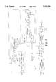
- FIG. 2sets forth a block diagram of the upstream transmitter of the present invention upstream data transmission system
- FIG. 3sets forth exemplary timing diagrams illustrating the operation of the present invention upstream data transmission system
- FIG. 4sets forth a block diagram of the upstream data transmitter of the present invention upstream data transmission system
- FIG. 5sets forth a block diagram of the cable system headend of the upstream data transmission system of the invention.
- FIG. 6is a table illustrating a model used by the network controller of FIG. 5 for controlling the operation of the upstream data transmission system of the invention.
- FIG. 1sets forth a block diagram of a cable television subscriber terminal constructed in accordance with the present invention and generally references by numeral 10.
- Subscriber terminal 10includes a tuner 12 coupled to a cable television distribution system (not shown) by a cable 11.
- the output of tuner 12is coupled to an intermediate frequency filter 13 and thereafter to the input of an intermediate frequency amplifier and demodulator circuit 14.
- the output of demodulator 14is coupled to an analog to digital converter 15, the output of which is coupled to the input of a digital logic circuit 16.
- a decryption circuit 17receives the output of logic circuit 16 and is coupled to a transport demultiplexor circuit 18.
- the outputs of demultiplexor 18are coupled to respective video and audio decompression circuits 19 and 30.
- Video decompression circuit 19includes a random access memory 20 coupled thereto.
- the output of video decompression circuit 19is coupled to a digital to analog converter 21 having an output 22 which is coupled to a video display.
- the output of audio decompression circuit 30is coupled to a digital to analog converter 31 having an output 32 coupled to an audio system.
- Subscriber terminal 10further includes a microprocessor 40 having a channel selection output 41 coupled to tuner 12 and having a bi-directional data coupling to demodulator 14, digital logic circuit 16, decryption circuit 17 and demultiplexor 18 (by which downstream data is downloaded to the microprocessor).
- Subscriber terminal 10further includes an upstream transmitter 50, the structure of which is set forth below in FIG. 2 in greater detail.
- Upstream transmitter 50includes an input 51 coupled to output 43 of microprocessor 40 together with a symbol clock input 52 coupled to logic circuit 16, a frame sync signal input 53 also coupled to digital logic circuit 16, and a superframe synchronization signal input 54 coupled to demultiplexor 18.
- a plurality of broadcast signalsare coupled by cable 11 to the input of tuner 12 which in response to a channel selection signal supplied by microprocessor 40 couples a selected signal to intermediate frequency filter 13.
- Filter 13may be constructed in accordance with conventional fabrication techniques and may, for example, include a conventional surface acoustic wave filter or its equivalent.
- the output of filter 13is demodulated by intermediate frequency amplifier and demodulator circuit 14.
- Demodulator 14may be constructed in accordance with conventional fabrication techniques and may, for example, include a synchronous demodulator.
- the essential function of demodulator 14is to recover the baseband analog signal modulated upon the carrier selected by tuner 12. While different transmitting signal formats and methods may be utilized in communicating data through a cable television system, the example shown in FIG.
- the demodulated baseband analog signal at the output of demodulator 14comprises successive N-level symbols equally spaced by the period of the symbol clock signal.
- the analog to digital conversion performed by converter 15is clocked at the symbol clock frequency to accurately recover the amplitudes of each symbol in the form of a multibit value.
- the output of converter 15is processed by digital logic circuit 16 to recover the frame sync signal in synchronism with the received frame and to generate the symbol clock signal for operating converter 15.
- the output data signal of digital logic circuit 16typically comprises compressed video and audio information and is further processed by decryption circuit 17 and thereafter demultiplexed in demultiplex circuit 18 to provide input video and audio signals to decompression circuits 19 and 30 respectively.
- Circuits 19 and 30perform conventional video and audio decompression operations upon the applied video and audio data to produce decompressed video and audio signals which are converted to corresponding analog signals within digital to analog converters 21 and 31.
- the analog signals thus providedare applied to the video display and audio system (not shown) respectively.
- upstream transmitter 50is coupled to cable 11 for upstream transmission and operates in response to a symbol clock input at input 52 from digital logic circuit 16 together with a frame sync signal input at input 53 also received from digital logic circuit 16.
- Upstream transmitter 50further responds to a superframe sync signal at input 54 which is provided by transport and demultiplexor 18.
- a programmable width signalis coupled from output 43 of microprocessor 40 to input 51 of upstream transmitter 50.
- Upstream transmitter 50utilizes the width signal, the superframe sync signal, the symbol clock and the frame sync signal to properly time upstream communication applied to cable 11 from subscriber terminal 10 by generating a plurality of message transmission time slots each of which may be uniquely assigned to a respective subscriber or which may be used as a contention time slot.
- the width and timing location of the time slots for subscriber terminal 10 as well as all other subscriber terminals on the cable television systemis programmably controllable by the headend manipulation of the width and superframe sync signals applied to the subscriber terminals.
- the time slots for each subscriber terminalare programmably controlled from the headend to accommodate dynamic changes within the cable television system, including establishing the time slots as contention or reserved and controlling the width and number of the slots.
- the upstream carrier signals and time slotsare synchronized with the symbol clock. This allows the use of a plurality of upstream carrier signals at different frequencies which are all locked to the symbol clock which makes the most efficient use of the available upstream bandwidth. Thus, with each carrier signal locked to a common reference, different subscriber terminals may readily transmit at different upstream carrier frequencies.
- the symbol clockis used in creating the subscriber time slots, the proper relative timing between time slots at each subscriber terminal is assured. That is to say, all time slots are synchronized to the common reference of the symbol clock.
- FIG. 2sets forth a block diagram of upstream transmitter 50 shown in FIG. 1.
- Upstream transmitter 50includes a slot width down counter 60 having a load input 61, a clock input 62, an output 63 and a preset input 64.
- a slot counter 65includes a clear input 66, a clock input 67, a clock enable input 68 and an output 69.
- a frame counter 80includes a clock enable input 81, a clock input 82, a clear input 83 and an output 84.
- Symbol clock input 52(corresponding to the downstream symbol rate) is coupled to clock input 62 of counter 60, clock enable input 67 of counter 65 and clock input 82 of counter 80.
- Superframe sync input 54is coupled to clear input 83 of counter 80.
- a frame sync input 53(corresponding to the downstream data frame sync signal) is coupled to load input 61 of counter 60, clear input 66 of counter 65 and clock input 81 of frame counter 80.
- Output 63 of counter 60is coupled to clock input 68 of slot counter 65.
- Microprocessor 40includes an output 49 coupled to preset input 64 of counter 60.
- Microprocessor 40further includes a tuning voltage output 56, a q signal output 59, a data output 57 and a status signal coupling 58.
- a comparator 85includes an input 86 coupled to output 69 of counter 65, an input 87 coupled to output 84 of frame counter 80, an input 89, and an output 88.
- a timing and control circuit 100includes an input 101 coupled to output 88 of comparator 85, an output 102, and a transmission clock signal input 103. Timing and control circuit 100 further includes a data input 105 coupled to data output 57 of microprocessor 40 and an input 106 coupled to status line input 58 of microprocessor 40.
- Timing and control circuit 100also includes a data output 111 and an address output 110 coupled to inputs 131 and 132 of a memory 130. Timing and control circuit 100 further includes a data output 109 and an address output 108 coupled to inputs 136 and 137 respectively of a memory 135.
- a multiplex circuit 140includes an input 141 coupled to output 107 of circuit 100, inputs 142 and 143 coupled to outputs 133 and 138 of memories 130 and 135 respectively, and an output 144.
- a slot register 115includes an output 116 coupled to input 89 of comparator 85, an enable input 117 coupled to output 102 of circuit 100, and an input 118 coupled to output 144 of multiplex 140.
- a time multiplex circuit 125includes an input 126 and an output 127.
- a transmission modulator 120includes a transmission clock output 121 coupled to input 103 of circuit 100 and a transmission enable input 122 coupled to output 104 of timing and control circuit 100. Transmission modulator 120 further includes a transmission data input 124 coupled to output 127 of multiplex circuit 125 and an output 123 coupled to cable 11 (seen in FIG. 1).
- processor 40provides a programmable slot width number to preset input 64 of down counter 60.
- Down counter 60responds to the next frame sync signal applied to load input 61 to set down counter 60 to the programmable slot width number.
- down counter 60responds to symbol clock signals at input 62 to count downwardly from the slot width number and produces an output signal at output 63 each time a zero count is obtained.
- slot width down counter 60recycles producing a plurality of successive output signals at output 63 each of which corresponds to the time interval in which counter 60 counts downwardly from the programmable slot width number.
- the succession of outputs from slot width counter 60is applied to clock enable input 68 of counter 65 which is cleared each time a frame sync signal is applied to clear input 66.
- Counter 65responds to the applied clock signals to produce an output count at output 69 synchronously with the symbol clock which corresponds to the sequentially established time slots created by slot width counter 60.
- the output of slot counter 65 at output 69provides a time slot identifying number which is applied to input 86 of comparator 85.
- Frame counter 80receives frame sync signals at clock enable input 81 to produce an output count at output 84 synchronously with the symbol clock which corresponds to the number of frame sync intervals which have occurred following the most recent superframe sync signal.
- the output count of frame counter 80is coupled to input 87 of comparator 85.
- the output of counter 65comprises a succession of eight-bit slot identifying numbers occurring within each data frame sync interval.
- the output of frame counter 80comprises an eight-bit running count identifying each successive frame which has occurred following the previous superframe sync signal.
- the combination of eight-bit output counts of counters 65 and 80when combined form a 16-bit number which identifies a plurality of periodically recurring time slots coextensive with one or more data frames of the received vestigial sideband signals.
- Each time slottherefore is uniquely identified by the combined number formed by the outputs of counters 65 and 80 in which the output of counter 65 forms the eight least significant bits of the number while the output of counter 80 forms the eight most significant bits of the time slot identifying number.
- This combined numberis utilized by comparator 85 to provide sequential identification of each time slot within each super frame as the vestigial sideband signal is received.
- each subscriber terminal within the networkmay be assigned a unique time slot or a contention time slot for upstream data transmission. Such assignments are made by downloading one or more time slot numbers to microprocessor 40 which can be used by the subscriber terminal for upstream transmissions as described in further detail hereinafter.
- a uniquely assigned time slot(sometimes referred to as a reserved time slot) can, of course, only be used by the respective subscriber terminal and thereby guarantees access to the network.
- all subscriber terminalsmay attempt upstream transmissions during contention time slots, a successful transmission resulting in the receipt of an "Acknowledge" signal by the terminal. In the case of an unsuccessful transmission, the message is normally retransmitted in a subsequent contention slot defined by a so-called "back-off" algorithm which may also be downloaded in microprocessor 40 by the network.
- Upstream transmitter 50initiates upstream data transmission by initially transferring a sixteen-bit time slot identifying number (which may represent either a reserved or contention time slot) to memory 130 through timing and control circuit 100.
- a sixteen-bit time slot identifying number(which may represent either a reserved or contention time slot)
- the eight least significant bits and eight most significant bitsare preferably loaded into different memory location to be accessed separately.
- the remaining memory locations within memory 130are filled with the data to be transmitted upstream (which is also transferred to the memory through timing and control circuit 100).
- the eight most significant bits which correspond to the frame identifying portion of the time slot identifying numberare coupled from memory 130 by multiplexor 140 to slot register 115.
- Comparator 85generates an internal match signal when the eight most significant bits of the time slot identifying number at input 89 match the eight most significant bits from counter 80. In response thereto, the eight least significant bits comprising the time slot identifying number from memory 130 are coupled through multiplexor 140 to slot register 115. Thereafter, slot register 115 applies the eight least significant bits to input 89 of comparator 85. Comparator 85 performs a comparison of the eight least significant bits of the time slot identifying number at input 89 to the current eight least significant bits at input 86 and produces an output signal at output 88 when a match occurs. In response to the match signal, timing and control circuit 100 then causes the stored data within memory 130 to be outputted to multiplexor 140 and thereafter to time multiplexor 125.
- Multiplexor 125converts the data to a serial data stream which is applied to modulator 120 forming the transmission data.
- timing and control circuit 100enables transmission modulator 120 causing the serial bit stream of transmission data to be transmitted upstream upon cable 11 (seen in FIG. 1) during the respective time slot.
- a second memory 135 identical to memory 130 and coupled to data and address outputs 109 and 108 respectivelyis also coupled to multiplex circuit 140.
- the purpose of providing memory 135is to utilize an alternating memory access for timing and control circuit 100 in which one memory may be loaded with data while the other is outputting data to transmit upstream. This improves the effectiveness and throughput capability of the present invention system.
- transmission modulator 120The operation of transmission modulator 120 is set forth below in greater detail. However, suffice it to note here that the serial data stream of transmission data is suitably modulated upon a carrier signal within the allowable range of upstream communication frequencies for processing by the cable system headend.
- FIG. 3sets forth exemplary timing diagrams illustrative of the operation of the present invention upstream data transmission system.
- a frame sync signal 150comprises a plurality of periodic reference sync signals such as pulses 151, 152, and 153 occurring at the beginning of each data frame. Pulses 151 through 153 correspond to recognizable symbol combinations within the transmitted downstream data frame which are recognized as frame sync signals.
- Timing diagram 155illustrates a plurality of time slots formed by slot width counter 60 and slot counter 65 utilizing a programmable slot width number which divides each frame sync interval into eight time slots. Thus, as can be seen in diagram 155, eight time slots (corresponding to the output of slot counter 65) are created within each interval between successive frame sync signals such as signals 151 through 153.
- superframe sync signals 160 and 165are shown for purposes of comparison and illustration. However, it will be apparent to those skilled in the art that different superframe sync signals may be utilized in accordance with the present invention.
- superframe sync signal 160generally coincides with frame sync signal 150 and thus a plurality of superframe sync intervals 161, 162 and so on are formed which generally coincide with frame sync intervals.
- superframe sync signal 165produces a superframe interval which includes two successive frame sync intervals.
- upstream transmissions from a subscriber terminalare affected within respective time slots represented by a sixteen-bit time slot identifying number having the eight least significant bits identifying the time slot and the eight most significant bits identifying the frame number (i.e. within a given superframe interval).
- the slot width or number time slots formed within each frame sync interval as well as the number of frames within each superframe intervalmay be varied to provide the necessary number of time slots for the subscriber terminals within the cable system.
- a total of eight time slotsare available. The number of time slots available may be increased by adjusting the programmable slot width number to cycle counter 60 (seen in FIG.
- timing diagram 170shows alternative time slots numbering eight and four respectively during each frame sync interval, for purposes of illustration, in practice a substantially greater number of time slots per frame sync interval will most likely be utilized to accommodate a large number of subscribers.
- timing diagrams 155 and 170illustrate the use of different programmable slot width numbers to provide different numbers of available time slots.
- the superframe intervalmay be adjusted to provide additional time slots as the superframe sync interval is lengthened. For example, in the event the slot width number is used which produces timing diagram 155 having eight time slots within each frame sync interval and superframe sync signal 160 is used, a total of eight time slots are provided. If, however, superframe sync signal 165 is utilized a total of sixteen time slots are provided during interval 166 of the superframe sync signal. In such case, the first eight time slots occur within the first frame of the superframe sync interval while an additional eight time slots occur during the second frame sync interval of the superframe signal.
- the sixteen-bit time slot identifying numberswould comprise an eight-bit frame count most significant bit number equal to decimal one and an eight-bit slot count least significant bit number equal to decimal three to uniquely identify time slot 156.
- an important objective of the present inventionis the utilization of programmable slot width together with programmable superframe signal values to provide dynamic configuration of the present invention upstream data transmission system.
- the headendis able to provide a sufficient number of time slots as system needs change by simply changing either or both the slot width or superframe signal values.
- the systemis completely flexible and able to accommodate changes in system needs such as an increased number of subscriber terminals or increased usage of the upstream transmission medium.
- any of the foregoing time slotsmay be used in a reserved mode wherein a given time slot is reserved only for usage by a particular terminal or in a contention mode wherein all terminals may attempt to use the time slot to gain access to the network, all under supervision of the network controller.
- upstream transmissions from the subscriber terminalsare received over cable 11 by a receiver 300 and supplied to a network controller 302.
- the output of network controller 302is combined with video and audio data in an inserter/modulator 304 and transmitted in the downstream direction in the format previously described.
- Network controller 302provides various data for downstream transmission including the superframe signal and data defining the modalities of the upstream transmission time slots.
- the table of FIG. 6illustrates a simplified strategy which may be used by network controller 302 in defining network time slot modality. Three parameters are considered in the table; upstream transmission power, the nature of the slot (i.e. reserved or contention) and the nature of the back-off algorithm employed for contention slots.
- the transmission mediumcomprises a hybrid-fiber-coaxial (HFC) transmission network so that instantaneous transmission power must be limited to prevent laser clipping.
- HFChybrid-fiber-coaxial
- the most effective upstream transmission scenariois represented by block 400, in which each system subscriber is assigned a unique reserved time slot for upstream transmission at a maximum allowable energy level.
- Network controller 302may establish this scenario by providing data for downstream transmission including slot width and superframe signals for establishing an adequate number of upstream transmission time slots (at least one per subscriber terminal) together with data assigning at least one unique time slot for usage by each respective terminal.
- the same scenariomay be used with increased upstream traffic as represented by blocks 402 and 404 since each terminal has its own reserved upstream transmission time slots.
- network controller 302may determine the extent of upstream traffic as a function of the number of successfully received upstream messages over a given period of time.
- the time slot mixis changed to 50% reserved and 50% contention.
- the transmission back-off algorithm for the contention slotsis increased to a selected medium value and the transmission power is reduced to 50% of maximum allowable energy.
- the transmission mixis further adjusted to provide 25% reserved and 75% contention time slots, with the latter using an increased retransmission back-off algorithm value and 25% maximum allowable energy.
- the table of FIG. 6represents a highly simplified model of the manner in which upstream transmission modes may be varied as a function of terminal population and upstream traffic and that many much more sophisticated models are possible.
- various other factorsmay be considered in defining the model such as the type of service requested. For example, it would be much more advantageous to assign a reserved slot to a terminal for use in playing an interactive game than for ordering a pay-per-view movie.
- FIG. 4sets forth a block diagram of transmission modulator 120 of FIG. 2 in greater detail.
- transmission modulator 120operates to modulate a selected carrier with the upstream data for transmission during a selected time slot to the cable system headend via the system network.
- the timing of upstream data transmissionis controlled by the upstream transmitter shown in FIG. 2 in accordance with the above-described time slot allotment leaving the function of transmission carrier modulation to transmission modulator 120.
- transmission modulator 120utilizes a discrete time oscillator 230 together with a phase lock loop 240 to provide a carrier signal at a selected frequency which is locked to a network reference such as the network symbol clock signal.
- Modulator 265receives the generated carrier signal together with the to-be-transmitted data and produces the modulated carrier used for upstream communication.
- transmission modulator 120includes discrete time oscillator 230 having a voltage controlled oscillator 200 having a tuning voltage input 201 coupled to output 56 of microprocessor 40 (seen in FIG. 2).
- Discrete time oscillator 230further includes a latch circuit 210 having a clock input 211 coupled to output 202 of oscillator 200, a Q output 213 and a D input 212.
- a summer 205includes an input 206, an input 207 coupled to output 59 of microprocessor 40, seen in FIG. 2, an input 208 coupled to the Q output 213 of latch 210, and an output 209.
- Output 209 of summer 205is coupled to an input 216 of a sine wave lookup table 215.
- output 209is further coupled to the D input 212 of latch 210.
- Sine lookup table 215includes an output 217 coupled to an input 219 of a comparator type slicing circuit 218.
- Transmission modulator 120further includes a phase lock loop 240 having a phase detector 242 having inputs 243 and 244 and an output 245.
- a frequency dividing circuit 241is coupled between output 220 of slicer 218 and input 243 of phase detector 242.
- a second frequency dividing network 251is coupled to input 244 of phase detector 242.
- Output 245 of phase detector 242is coupled to an input 248 of a latch circuit 247 via a low pass filter 246.
- Latch 247includes a clock input 249 coupled to the input of frequency dividing network 251 and an output 250 coupled to input 206 of summer 205.
- Transmission modulator 120includes a clock signal input 121 coupled to the input of frequency divider network 251 and which comprises the symbol clock from input 52 seen in FIG. 2.
- transmission modulator 120includes an input 124 which receives the serial bit stream of data for upstream transmission.
- Transmission modulator 120further includes a signal constellation coding circuit 260 which may for example comprise a conventional byphase shift key coding circuit which appropriately codes the serial bit data steam of upstream transmission data and applies it to an input 257 of a low pass filter 255.
- Filter 255includes a clock signal input 256 coupled to symbol clock input 121.
- Output 258 of low pass filter 255is coupled to input 262 of modulator 265.
- Modulator 265includes an input 261 coupled to output 217 of sine wave lookup table 215 and an output 263.
- a channel filter 264couples output 263 to an input 267 of a variable attenuator 266.
- Attenuator 266, which is controlled by a signal from microprocessor 40 to establish the upstream transmission energy,includes an output 268 coupled to cable 11 (seen in FIG. 1).
- microprocessor 40(seen in FIG. 2) produces initial values of the tuning voltage and value "q" for application to input 201 of oscillator 200 and to input 207 of summing network 205.
- These initial values of tuning voltage and input signal "q" to summing network 205are programmable values selected to generate an output carrier having one of a plurality of frequencies within the upstream communication bandwidth of the system. Typically, such upsteam communications are modulated upon carriers having frequencies within a range of 5-30 Megahertz.
- Oscillator 200is a voltage controlled oscillator producing an output signal having a frequency determined by the tuning voltage input. Thus, the output signal of oscillator 200 is applied to the clock input of latch 210 having a Q output applied to one input of summing network 205.
- an output combined signalis applied to sine wave lookup table 215.
- Sine wave lookup table 215responds to the input data at input 216 to produce a stream of digital values which are converted by slicer 218 to an output square wave or clock signal at the frequency of the sine wave produced by the values of lookup table 215.
- the output square wave signal from slicer 218is applied to a divide by M frequency divider 241 which forms one input to phase detector 242.
- the input symbol clock signal received at input 121is frequency divided within divider 251 using a divide by N frequency division and applied to the remaining input of phase detector 242.
- the combination of frequency dividers 241 and 251 together with phase detector 242is used to provide a carrier frequency for upstream communication which is locked to a network reference signal which is common to all subscriber terminals.
- the common network reference selectedis that of the symbol clock signal.
- phase detector 242provides a frequency and phase comparison of the frequency divided input signals at inputs 243 and 244 and produces an output error signal representing the phase and frequency difference between the divided carrier signal and the divided symbol clock signal.
- This error signalis filtered by low pass filter 246 and applied to data input 248 of latch 247.
- Latch 247is clocked by the symbol clock signal.
- the output signal of latch 247 representing the phase and frequency error signalis applied to input 206 of summing network 205.
- the application of the output error signal of latch 247 to input 206 of summing network 205closes the control loop for discrete time oscillator 230 and phase lock loop 240 which operates to frequency and phase lock the carrier signal produced by discrete time oscillator 230 to the symbol clock signal.
- the carrier frequency signal produced by discrete time oscillator 230is applied to one input of modulator 265.
- the transmission datais properly coded by coding circuit 260 and filtered by filter 255 for application to the remaining input of modulator 265.
- the output of modulator 265comprises a carrier having the carrier frequency produced by discrete time oscillator 230 modulated with the properly coded transmission data.
- Channel filter 264filters the undesired modulation components from the modulated carrier signal and applies the desired modulated carrier to cable 11 (seen in FIG. 1) through programmable attenuator 266 for upstream communication.
- the frequency of the carrier signalis controlled by programmable values of tuning voltage as well as frequency divider values M and N.
- the carrier frequency of transmission modulator 120is readily established or changed using the programmable values providing substantial flexibility for the present invention upstream data transmission system.
- the disclosed upstream transmission systemcan also be used in a network where the downstream signals are of an analog nature, or a hybrid network where some of the downstream signals are analog and some are digital.
- the time slotswould be synchronized to an appropriate reference parameter of the downstream analog signal and a downstream data channel such as the analog signal VBI (or preferably an out-of-band FM channel) would be used to download the upstream parameter values to microprocessor 40. Therefore, the aim in the appended claims is to cover all such changes and modifications as fall within the true spirit and scope of the invention.
Landscapes
- Engineering & Computer Science (AREA)
- Signal Processing (AREA)
- Multimedia (AREA)
- Computer Networks & Wireless Communication (AREA)
- Two-Way Televisions, Distribution Of Moving Picture Or The Like (AREA)
Abstract
Description
This application is a continuation-in-part of application Ser. No. 08/337,796, filed Nov. 14, 1994 now abandoned.
This invention relates generally to upstream data transmission in a two-way cable system and particularly to a system for generating transmission time slots for upstream data transmission.
Cable television systems utilize a central provider of program information which services a large number of end users generally referred to as subscribers. The central provider portion of the cable television system usually called the "headend" provides a plurality of program information as well as other information to the subscribers via a multiple branch distribution network which may define several tiers of distribution facilities.
In addition to actual programming information, the cable television system is required to carry additional management and operating data provided by the headend to the large number of end users or subscribers. Communication from the headend to the subscribers is generally referred to as "downstream" communication. In some cable television systems referred to as one-way, all information and data is transferred downstream. In other cable television systems referred to as two-way systems, communication is also provided from the various subscribers throughout the network to the headend in what is referred to as "upstream" communication. Examples of subscriber originated upstream information may include program purchasing requests, opinion poll responses, and subscriber terminal status information. Upstream communication in cable television systems is provided using out-of-band communication. Such out-of-band communication uses a separate communication capability outside the standard television broadcast channel and thus is not limited to the vertical blanking interval or other time restraint. Instead, a separate carrier, usually between five and thirty megahertz, is modulated with upstream data at the decoder and transmitted to the headend.
Upstream communications are typically effected using either a contention protocol as disclosed in U.S. Pat. Nos. 4,528,663 and 4,553,161 wherein the subscriber's contend for access to the upstream channel or by providing each subscriber with guaranteed access to a respective relatively small portion of the upstream spectrum. Depending on the type and quantity of usage, one protocol may be more advantageous than the other, or a mixture of both may provide the most effective performance.
It is a general object of the present invention to provide an improved upstream data transmission system for cable television. It is a more particular object of the present invention to provide an improved upstream data transmission system for cable television which is able to respond dynamically to operating changes within the cable television system using headend controlled programmable system parameters.
The features of the present invention, which are believed to be novel, are set forth with particularlity in the appended claims. The invention, together with further objects and advantages thereof, may best be understood by reference to the following description taken in conjunction with the accompanying drawings, in the several figures of which like reference numerals identify like elements and in which:
FIG. 1 sets forth a general block diagram of a cable television subscriber decoder constructed in accordance with the present invention;
FIG. 2 sets forth a block diagram of the upstream transmitter of the present invention upstream data transmission system;
FIG. 3 sets forth exemplary timing diagrams illustrating the operation of the present invention upstream data transmission system;
FIG. 4 sets forth a block diagram of the upstream data transmitter of the present invention upstream data transmission system;
FIG. 5 sets forth a block diagram of the cable system headend of the upstream data transmission system of the invention; and
FIG. 6 is a table illustrating a model used by the network controller of FIG. 5 for controlling the operation of the upstream data transmission system of the invention.
FIG. 1 sets forth a block diagram of a cable television subscriber terminal constructed in accordance with the present invention and generally references bynumeral 10.Subscriber terminal 10 includes atuner 12 coupled to a cable television distribution system (not shown) by acable 11. The output oftuner 12 is coupled to anintermediate frequency filter 13 and thereafter to the input of an intermediate frequency amplifier anddemodulator circuit 14. The output ofdemodulator 14 is coupled to an analog todigital converter 15, the output of which is coupled to the input of adigital logic circuit 16. Adecryption circuit 17 receives the output oflogic circuit 16 and is coupled to atransport demultiplexor circuit 18. The outputs ofdemultiplexor 18 are coupled to respective video andaudio decompression circuits Video decompression circuit 19 includes arandom access memory 20 coupled thereto. The output ofvideo decompression circuit 19 is coupled to a digital toanalog converter 21 having anoutput 22 which is coupled to a video display. Correspondingly, the output ofaudio decompression circuit 30 is coupled to a digital toanalog converter 31 having anoutput 32 coupled to an audio system.
In operation, a plurality of broadcast signals are coupled bycable 11 to the input oftuner 12 which in response to a channel selection signal supplied bymicroprocessor 40 couples a selected signal tointermediate frequency filter 13.Filter 13 may be constructed in accordance with conventional fabrication techniques and may, for example, include a conventional surface acoustic wave filter or its equivalent. The output offilter 13 is demodulated by intermediate frequency amplifier anddemodulator circuit 14.Demodulator 14 may be constructed in accordance with conventional fabrication techniques and may, for example, include a synchronous demodulator. The essential function ofdemodulator 14 is to recover the baseband analog signal modulated upon the carrier selected bytuner 12. While different transmitting signal formats and methods may be utilized in communicating data through a cable television system, the example shown in FIG. 1 utilizes a digital vestigial sideband system in sync signal having a frequency of approximately 41.2 kilohertz resulting in data frames of approximately 24.3 milliseconds in duration. The demodulated baseband analog signal at the output ofdemodulator 14 comprises successive N-level symbols equally spaced by the period of the symbol clock signal. The analog to digital conversion performed byconverter 15 is clocked at the symbol clock frequency to accurately recover the amplitudes of each symbol in the form of a multibit value. The output ofconverter 15 is processed bydigital logic circuit 16 to recover the frame sync signal in synchronism with the received frame and to generate the symbol clock signal foroperating converter 15. The output data signal ofdigital logic circuit 16 typically comprises compressed video and audio information and is further processed bydecryption circuit 17 and thereafter demultiplexed indemultiplex circuit 18 to provide input video and audio signals todecompression circuits Circuits analog converters
The structure ofupstream transmitter 50 is set forth below in FIG. 2 in greater detail. However, suffice it to note here that in accordance with the present invention,upstream transmitter 50 is coupled tocable 11 for upstream transmission and operates in response to a symbol clock input atinput 52 fromdigital logic circuit 16 together with a frame sync signal input atinput 53 also received fromdigital logic circuit 16.Upstream transmitter 50 further responds to a superframe sync signal atinput 54 which is provided by transport anddemultiplexor 18. In further accordance with the present invention, a programmable width signal is coupled fromoutput 43 ofmicroprocessor 40 to input 51 ofupstream transmitter 50.Upstream transmitter 50 utilizes the width signal, the superframe sync signal, the symbol clock and the frame sync signal to properly time upstream communication applied tocable 11 fromsubscriber terminal 10 by generating a plurality of message transmission time slots each of which may be uniquely assigned to a respective subscriber or which may be used as a contention time slot. In accordance with an important aspect of the present invention set forth below in greater detail, the width and timing location of the time slots forsubscriber terminal 10 as well as all other subscriber terminals on the cable television system is programmably controllable by the headend manipulation of the width and superframe sync signals applied to the subscriber terminals. Thus, in accordance with the present invention, the time slots for each subscriber terminal are programmably controlled from the headend to accommodate dynamic changes within the cable television system, including establishing the time slots as contention or reserved and controlling the width and number of the slots.
In accordance with an important aspect of the present invention, the upstream carrier signals and time slots are synchronized with the symbol clock. This allows the use of a plurality of upstream carrier signals at different frequencies which are all locked to the symbol clock which makes the most efficient use of the available upstream bandwidth. Thus, with each carrier signal locked to a common reference, different subscriber terminals may readily transmit at different upstream carrier frequencies.
In addition, because the symbol clock is used in creating the subscriber time slots, the proper relative timing between time slots at each subscriber terminal is assured. That is to say, all time slots are synchronized to the common reference of the symbol clock.
FIG. 2 sets forth a block diagram ofupstream transmitter 50 shown in FIG. 1.Upstream transmitter 50 includes a slot width down counter 60 having aload input 61, aclock input 62, anoutput 63 and apreset input 64. Aslot counter 65 includes aclear input 66, aclock input 67, a clock enableinput 68 and anoutput 69. Aframe counter 80 includes a clock enableinput 81, aclock input 82, aclear input 83 and anoutput 84. Symbol clock input 52 (corresponding to the downstream symbol rate) is coupled toclock input 62 ofcounter 60, clock enableinput 67 ofcounter 65 andclock input 82 ofcounter 80.Superframe sync input 54 is coupled toclear input 83 ofcounter 80. A frame sync input 53 (corresponding to the downstream data frame sync signal) is coupled to loadinput 61 ofcounter 60,clear input 66 ofcounter 65 andclock input 81 offrame counter 80.Output 63 ofcounter 60 is coupled toclock input 68 ofslot counter 65.
In operation,processor 40 provides a programmable slot width number to presetinput 64 ofdown counter 60. Downcounter 60 responds to the next frame sync signal applied to loadinput 61 to set down counter 60 to the programmable slot width number. Thereafter, down counter 60 responds to symbol clock signals atinput 62 to count downwardly from the slot width number and produces an output signal atoutput 63 each time a zero count is obtained. Thereafter, slot width downcounter 60 recycles producing a plurality of successive output signals atoutput 63 each of which corresponds to the time interval in which counter 60 counts downwardly from the programmable slot width number. The succession of outputs fromslot width counter 60 is applied to clock enableinput 68 ofcounter 65 which is cleared each time a frame sync signal is applied toclear input 66.Counter 65 responds to the applied clock signals to produce an output count atoutput 69 synchronously with the symbol clock which corresponds to the sequentially established time slots created byslot width counter 60. Thus, the output ofslot counter 65 atoutput 69 provides a time slot identifying number which is applied to input 86 ofcomparator 85.Frame counter 80 receives frame sync signals at clock enableinput 81 to produce an output count atoutput 84 synchronously with the symbol clock which corresponds to the number of frame sync intervals which have occurred following the most recent superframe sync signal. The output count offrame counter 80 is coupled to input 87 ofcomparator 85.
Thus, the output ofcounter 65 comprises a succession of eight-bit slot identifying numbers occurring within each data frame sync interval. Correspondingly, the output offrame counter 80 comprises an eight-bit running count identifying each successive frame which has occurred following the previous superframe sync signal. As a result, the combination of eight-bit output counts ofcounters counters counter 65 forms the eight least significant bits of the number while the output ofcounter 80 forms the eight most significant bits of the time slot identifying number. This combined number is utilized bycomparator 85 to provide sequential identification of each time slot within each super frame as the vestigial sideband signal is received.
In further accordance with the present invention, each subscriber terminal within the network may be assigned a unique time slot or a contention time slot for upstream data transmission. Such assignments are made by downloading one or more time slot numbers tomicroprocessor 40 which can be used by the subscriber terminal for upstream transmissions as described in further detail hereinafter. A uniquely assigned time slot (sometimes referred to as a reserved time slot) can, of course, only be used by the respective subscriber terminal and thereby guarantees access to the network. On the other hand, all subscriber terminals may attempt upstream transmissions during contention time slots, a successful transmission resulting in the receipt of an "Acknowledge" signal by the terminal. In the case of an unsuccessful transmission, the message is normally retransmitted in a subsequent contention slot defined by a so-called "back-off" algorithm which may also be downloaded inmicroprocessor 40 by the network.
To further enhance the effectiveness ofupstream transmitter 50, asecond memory 135 identical tomemory 130 and coupled to data and addressoutputs multiplex circuit 140. The purpose of providingmemory 135 is to utilize an alternating memory access for timing andcontrol circuit 100 in which one memory may be loaded with data while the other is outputting data to transmit upstream. This improves the effectiveness and throughput capability of the present invention system.
The operation oftransmission modulator 120 is set forth below in greater detail. However, suffice it to note here that the serial data stream of transmission data is suitably modulated upon a carrier signal within the allowable range of upstream communication frequencies for processing by the cable system headend.
FIG. 3 sets forth exemplary timing diagrams illustrative of the operation of the present invention upstream data transmission system. For purposes of references, aframe sync signal 150 comprises a plurality of periodic reference sync signals such aspulses Pulses 151 through 153 correspond to recognizable symbol combinations within the transmitted downstream data frame which are recognized as frame sync signals. Timing diagram 155 illustrates a plurality of time slots formed byslot width counter 60 andslot counter 65 utilizing a programmable slot width number which divides each frame sync interval into eight time slots. Thus, as can be seen in diagram 155, eight time slots (corresponding to the output of slot counter 65) are created within each interval between successive frame sync signals such assignals 151 through 153. A pair of alternative superframe sync signals 160 and 165 are shown for purposes of comparison and illustration. However, it will be apparent to those skilled in the art that different superframe sync signals may be utilized in accordance with the present invention. For purposes of illustrations, superframe sync signal 160 generally coincides withframe sync signal 150 and thus a plurality ofsuperframe sync intervals superframe sync signal 165 produces a superframe interval which includes two successive frame sync intervals.
As described above, upstream transmissions from a subscriber terminal are affected within respective time slots represented by a sixteen-bit time slot identifying number having the eight least significant bits identifying the time slot and the eight most significant bits identifying the frame number (i.e. within a given superframe interval). As is also described above, the slot width or number time slots formed within each frame sync interval as well as the number of frames within each superframe interval may be varied to provide the necessary number of time slots for the subscriber terminals within the cable system. Thus, for example, in the eventsuperframe sync signal 160 is used, a total of eight time slots are available. The number of time slots available may be increased by adjusting the programmable slot width number to cycle counter 60 (seen in FIG. 2) more quickly and thereby divide each frame sync interval into a greater number of narrower time slots. Conversely, the programmable slot width number applied to counter 60 in FIG. 2 may be increased to divide each frame sync interval into a smaller number of time slots such as illustrated in timing diagram 170 in which four time slots per frame sync interval are provided. It will be understood by those skilled in the art that while timing diagrams 155 and 170 show alternative time slots numbering eight and four respectively during each frame sync interval, for purposes of illustration, in practice a substantially greater number of time slots per frame sync interval will most likely be utilized to accommodate a large number of subscribers.
Thus, timing diagrams 155 and 170 illustrate the use of different programmable slot width numbers to provide different numbers of available time slots. In addition, the superframe interval may be adjusted to provide additional time slots as the superframe sync interval is lengthened. For example, in the event the slot width number is used which produces timing diagram 155 having eight time slots within each frame sync interval andsuperframe sync signal 160 is used, a total of eight time slots are provided. If, however,superframe sync signal 165 is utilized a total of sixteen time slots are provided duringinterval 166 of the superframe sync signal. In such case, the first eight time slots occur within the first frame of the superframe sync interval while an additional eight time slots occur during the second frame sync interval of the superframe signal. Thus, changing fromsuperframe signal 160 to superframe signal 165 doubles the number of time slots available. If, for example,shaded time slot 156 is to be identified, the sixteen-bit time slot identifying numbers would comprise an eight-bit frame count most significant bit number equal to decimal one and an eight-bit slot count least significant bit number equal to decimal three to uniquely identifytime slot 156.
As mentioned above, an important objective of the present invention is the utilization of programmable slot width together with programmable superframe signal values to provide dynamic configuration of the present invention upstream data transmission system. Thus, in accordance with the present invention, the headend is able to provide a sufficient number of time slots as system needs change by simply changing either or both the slot width or superframe signal values. As a result, the system is completely flexible and able to accommodate changes in system needs such as an increased number of subscriber terminals or increased usage of the upstream transmission medium.
As mentioned previously, any of the foregoing time slots may be used in a reserved mode wherein a given time slot is reserved only for usage by a particular terminal or in a contention mode wherein all terminals may attempt to use the time slot to gain access to the network, all under supervision of the network controller. In particular, referring to FIG. 5, upstream transmissions from the subscriber terminals are received overcable 11 by areceiver 300 and supplied to anetwork controller 302. The output ofnetwork controller 302 is combined with video and audio data in an inserter/modulator 304 and transmitted in the downstream direction in the format previously described.
Referring in more detail to FIG. 6, assuming a relatively small population of subscriber terminals, i.e. less than Po, and relatively low upstream traffic, i.e. less than To, the most effective upstream transmission scenario is represented by block 400, in which each system subscriber is assigned a unique reserved time slot for upstream transmission at a maximum allowable energy level.Network controller 302 may establish this scenario by providing data for downstream transmission including slot width and superframe signals for establishing an adequate number of upstream transmission time slots (at least one per subscriber terminal) together with data assigning at least one unique time slot for usage by each respective terminal. The same scenario may be used with increased upstream traffic as represented byblocks network controller 302 may determine the extent of upstream traffic as a function of the number of successfully received upstream messages over a given period of time.
As the population of subscriber terminals increases, for example greater than Po but less then P1, it becomes impractical to assign a unique time slot to each terminal. Thus, if upstream traffic is relatively low, as represented byblock network controller 302 for downloading a minimum retransmission backoff algorithm and limiting transmission power to 75% of maximum allowable energy. As the upstream traffic increases as represented by block 408 (more than To but less than T1) the time slot mix is changed to 50% reserved and 50% contention. Also, the transmission back-off algorithm for the contention slots is increased to a selected medium value and the transmission power is reduced to 50% of maximum allowable energy. With further increases in upstream traffic as represented by block 410 (more than T1 but less than T2) the transmission mix is further adjusted to provide 25% reserved and 75% contention time slots, with the latter using an increased retransmission back-off algorithm value and 25% maximum allowable energy.
Further increases in subscriber terminal population as represented by blocks 412-416 (more than P1) makes the use of any reserved slots impractical so that all upstream transmission time slots are used in a contention mode. As illustrated in the table, the retransmission back-off increases and the transmission power decreases with increasing upstream traffic.
It will be appreciated that the table of FIG. 6 represents a highly simplified model of the manner in which upstream transmission modes may be varied as a function of terminal population and upstream traffic and that many much more sophisticated models are possible. In addition, various other factors may be considered in defining the model such as the type of service requested. For example, it would be much more advantageous to assign a reserved slot to a terminal for use in playing an interactive game than for ordering a pay-per-view movie.
FIG. 4 sets forth a block diagram oftransmission modulator 120 of FIG. 2 in greater detail. As is seen in FIG. 2,transmission modulator 120 operates to modulate a selected carrier with the upstream data for transmission during a selected time slot to the cable system headend via the system network. The timing of upstream data transmission is controlled by the upstream transmitter shown in FIG. 2 in accordance with the above-described time slot allotment leaving the function of transmission carrier modulation totransmission modulator 120. Thus,transmission modulator 120 utilizes adiscrete time oscillator 230 together with aphase lock loop 240 to provide a carrier signal at a selected frequency which is locked to a network reference such as the network symbol clock signal.Modulator 265 receives the generated carrier signal together with the to-be-transmitted data and produces the modulated carrier used for upstream communication.
More specifically,transmission modulator 120 includesdiscrete time oscillator 230 having a voltage controlledoscillator 200 having a tuningvoltage input 201 coupled tooutput 56 of microprocessor 40 (seen in FIG. 2).Discrete time oscillator 230 further includes alatch circuit 210 having aclock input 211 coupled tooutput 202 ofoscillator 200, aQ output 213 and aD input 212. Asummer 205 includes aninput 206, aninput 207 coupled tooutput 59 ofmicroprocessor 40, seen in FIG. 2, aninput 208 coupled to theQ output 213 oflatch 210, and anoutput 209.Output 209 ofsummer 205 is coupled to aninput 216 of a sine wave lookup table 215. In addition,output 209 is further coupled to theD input 212 oflatch 210. Sine lookup table 215 includes anoutput 217 coupled to aninput 219 of a comparatortype slicing circuit 218.
As mentioned above,transmission modulator 120 includes aninput 124 which receives the serial bit stream of data for upstream transmission.Transmission modulator 120 further includes a signalconstellation coding circuit 260 which may for example comprise a conventional byphase shift key coding circuit which appropriately codes the serial bit data steam of upstream transmission data and applies it to aninput 257 of alow pass filter 255.Filter 255 includes aclock signal input 256 coupled tosymbol clock input 121. Output 258 oflow pass filter 255 is coupled to input 262 ofmodulator 265.Modulator 265 includes aninput 261 coupled tooutput 217 of sine wave lookup table 215 and anoutput 263. Achannel filter 264couples output 263 to aninput 267 of avariable attenuator 266.Attenuator 266, which is controlled by a signal frommicroprocessor 40 to establish the upstream transmission energy, includes anoutput 268 coupled to cable 11 (seen in FIG. 1).
In operation, microprocessor 40 (seen in FIG. 2) produces initial values of the tuning voltage and value "q" for application to input 201 ofoscillator 200 and to input 207 of summingnetwork 205. These initial values of tuning voltage and input signal "q" to summingnetwork 205 are programmable values selected to generate an output carrier having one of a plurality of frequencies within the upstream communication bandwidth of the system. Typically, such upsteam communications are modulated upon carriers having frequencies within a range of 5-30 Megahertz.Oscillator 200 is a voltage controlled oscillator producing an output signal having a frequency determined by the tuning voltage input. Thus, the output signal ofoscillator 200 is applied to the clock input oflatch 210 having a Q output applied to one input of summingnetwork 205. With the value q input to summingnetwork 205 established by microprocessor 40 (seen in FIG. 2), an output combined signal is applied to sine wave lookup table 215. For purposes of speed and efficiency, only a predetermined number of the most significant bits within the output data ofsummer 205 are required for input to sine wave lookup table 215. Sine wave lookup table 215 responds to the input data atinput 216 to produce a stream of digital values which are converted byslicer 218 to an output square wave or clock signal at the frequency of the sine wave produced by the values of lookup table 215. The output square wave signal fromslicer 218 is applied to a divide byM frequency divider 241 which forms one input to phasedetector 242.
Concurrently, the input symbol clock signal received atinput 121 is frequency divided withindivider 251 using a divide by N frequency division and applied to the remaining input ofphase detector 242. The combination offrequency dividers phase detector 242 is used to provide a carrier frequency for upstream communication which is locked to a network reference signal which is common to all subscriber terminals. Thus, as each transmission modulator within the cable television system uses carrier frequencies for upstream data communication which are all locked to a common network reference, the available bandwidth of upstream frequencies will be used with maximum efficiency. In the example shown in FIG. 4, the common network reference selected is that of the symbol clock signal. Thus, it is anticipated that other transmission modulators similar totransmission modulator 120 within the host cable television system will utilize different upstream carrier frequencies each locked to the common network reference provided by the symbol clock signal.
Accordingly, the values of M and N selected forfrequency dividers Phase detector 242 provides a frequency and phase comparison of the frequency divided input signals atinputs low pass filter 246 and applied to data input 248 oflatch 247.Latch 247 is clocked by the symbol clock signal. The output signal oflatch 247 representing the phase and frequency error signal is applied to input 206 of summingnetwork 205. The application of the output error signal oflatch 247 to input 206 of summingnetwork 205 closes the control loop fordiscrete time oscillator 230 andphase lock loop 240 which operates to frequency and phase lock the carrier signal produced bydiscrete time oscillator 230 to the symbol clock signal.
Thus, in the event the frequency of carrier signal is less than its desired value, a positive error signal will be developed at the output oflatch 247. In response, the output ofsummer 205 will increase at a more rapid rate thereby increasing the carrier frequency output signal of lookup table 215. Conversely, in the event the frequency of the carrier signal produced bydiscrete time oscillator 230 is greater than its desired value, a negative error signal will be produced at the output oflatch 250 which in turn will decrease the rate of signal increase at the output ofsummer 205 thereby decreasing the frequency of carrier signal at the output of lookup table 215. When the carrier signal and symbol clock signal are properly phase and frequency locked, the value of error signal at the output oflatch 250 will be zero.
The carrier frequency signal produced bydiscrete time oscillator 230 is applied to one input ofmodulator 265. The transmission data is properly coded by codingcircuit 260 and filtered byfilter 255 for application to the remaining input ofmodulator 265. The output ofmodulator 265 comprises a carrier having the carrier frequency produced bydiscrete time oscillator 230 modulated with the properly coded transmission data.Channel filter 264 filters the undesired modulation components from the modulated carrier signal and applies the desired modulated carrier to cable 11 (seen in FIG. 1) throughprogrammable attenuator 266 for upstream communication.
It should be noted that the frequency of the carrier signal is controlled by programmable values of tuning voltage as well as frequency divider values M and N. Thus, the carrier frequency oftransmission modulator 120 is readily established or changed using the programmable values providing substantial flexibility for the present invention upstream data transmission system.
While particular embodiments of the invention have been shown and described, it will be obvious to those skilled in the art that changes and modifications may be made without departing from the invention in its broader aspects. For example, the disclosed upstream transmission system can also be used in a network where the downstream signals are of an analog nature, or a hybrid network where some of the downstream signals are analog and some are digital. Where a decoder capable of only processing the downstream analog signals is used, the time slots would be synchronized to an appropriate reference parameter of the downstream analog signal and a downstream data channel such as the analog signal VBI (or preferably an out-of-band FM channel) would be used to download the upstream parameter values tomicroprocessor 40. Therefore, the aim in the appended claims is to cover all such changes and modifications as fall within the true spirit and scope of the invention.
Claims (20)
1. An upstream data transmission system for use in a cable television system in which downstream data transmission is carried out using data frames and a periodic data frame synchronization signal via a cable network from a headend to a plurality of subscriber terminals, said upstream data transmission system comprising:
time slot means for dividing said data frames into a plurality of time slots in response to a downloadable slot width signal;
superframe means for combining one or more of said data frames into a superframe interval in which each data frame is sequentially numbered in response to a downloadable superframe signal;
means for assigning a time slot to a subscriber terminal expressed as a time slot identifier having a frame number within said superframe and a slot number within said numbered frame; and
timing means for transmitting upstream data from a subscriber terminal to said headend during said assigned time slot.
2. An upstream data transmission system as set forth in claim 1 wherein said downstream data frames comprise a plurality of N-level symbols occurring at a predetermined symbol rate, said upstream data transmission system including means for generating a symbol clock signal having a frequency corresponding to said predetermined rate, said time slot means and said superframe means comprising counting means synchronously operated in response to said symbol clock signal.
3. An upstream data transmission system as set forth in claim 1 wherein said plurality of time slots are substantially equal and wherein said time slot means includes a repetitive down counter and means for loading said down counter with a numeric value of said slot width signal.
4. An upstream data transmission system as set forth in claim 3 wherein said means for loading said down counter includes means responsive to said data frame synchronization signal.
5. An upstream data transmission system as set forth in claim 4 wherein said down counter produces an output signal each time a predetermined count is reached and wherein said time slot means includes a slot counter responsive to said output signal to count said time slots between said data frame synchronization signals and output a slot count number.
6. An upstream data transmission system as set forth in claim 5 wherein said superframe means includes a frame counter for counting said data frame synchronizing signals between each superframe signal and outputting a frame count number.
7. An upstream data transmission system as set forth in claim 6 wherein said timing means includes:
comparator means coupled to said slot counter and said frame counter; and
first memory means for storing said time slot identifier for said subscriber terminal together with an upstream data message;
said comparator means comparing said frame count and slot count numbers to said stored time slot identifier and causing said timing means to initiate upstream transmission of said data message when a match is found.
8. An upstream data transmission system as set forth in claim 7 wherein said timing means further includes a second memory means for storing said time slot identifier together with an upstream data message.
9. An upstream data transmission system as set forth in claim 7 wherein said frame count number corresponds to the most significant bits of said time slot identifier and said slot count number corresponds to the least significant bits of said time slot identifier.
10. An upstream data transmission system as set forth in claim 9 wherein said comparator means includes a register coupled to said first memory means and wherein said most significant bits of said time slot identifier is initially stored in said register for match to said frame count number and said least significant bits of said time slot identifier are stored in said register once a frame number match is detected and thereafter said least significant bits of said time slot identifier are compared to said slot count number to detect a match.
11. In a cable television system in which a plurality of subscriber terminals are coupled to a headend by a network and in which a plurality of data frames, each comprising a plurality of N-level data symbols occurring at a predetermined symbol rate and a periodic data frame synchronization signal, are transmitted downstream from said headend to said subscriber terminals, an upstream data transmission method comprising the steps of:
generating a symbol clock having a frequency corresponding to said predetermined rate;
dividing each of said data frames into a plurality of time slots synchronously with said symbol clock, each of said time slots having a duration corresponding to a downloadable slot width value;
forming a superframe synchronously with said symbol clock composed of one or more sequential data frames corresponding to a downloadable superframe value;
assigning a time slot to a subscriber terminal for upstream data communication expressed as a time slot identifier having a frame number within said superframe and a slot number therein; and
timing upstream data communication from a subscriber terminal to said headend to occur during said assigned time slot.
12. The upstream data transmission method set forth in claim 11 wherein said forming step includes the steps of:
providing a periodic superframe synchronizing signal synchronously with said data frame synchronizing signal and having a period equal to an integer multiple of the period of said data frame synchronizing signal; and
counting sequential data frames between said superframe synchronizing signals to establish frame count numbers in each superframe.
13. The upstream data transmission method set forth in claim 12 wherein said dividing step includes the step of sequentially numbering said time slots within each data frame to establish slot count numbers.
14. The upstream data transmission method set forth in claim 13 wherein said timing step includes the steps of:
first comparing the frame number of said assigned time slot of a subscriber terminal to said frame count numbers until a match is detected;
second comparing the slot number of said assigned time slot of a subscriber terminal to said slot count numbers within said matching frame of downstream data until a match is detected; and
initiating upsteam data transmission during the matching slot.
15. In a cable television system in which a plurality of subscriber terminals are coupled to a headend by a network and in which a plurality of data frames, each comprising a plurality of N-level data symbols occurring at a predetermined rate and a periodic data frame synchronization signal, are transmitted downstream from said headend to said subscriber terminals, an upstream data transmission system comprising:
means for generating a symbol clock signal having a frequency corresponding to said predetermined rate;
means responsive to said symbol clock signal for dividing each data frame into a plurality of time slots having a duration corresponding to a downloadable width value;
means responsive to said symbol clock signal for forming a superframe composed of one or more sequential data frames corresponding to a downloadable superframe value;
means for assigning a time slot to a subscriber terminal for upstream data communication expressed as a time slot identifier having a frame number within said superframe and a slot number therein; and
means for timing upstream data communications from a subscriber terminal to said headend to occur during the assigned time slot for the transmitting subscriber terminal.
16. The upstream data transmission system set forth in claim 15 wherein said means for forming includes:
means for providing a periodic superframe synchronizing signal synchronously with said data frame synchronizing signal and having a period equal to an integer multiple of the period of said data frame synchronizing signal; and
means for counting sequential data frames between said superframe synchronizing signals to establish frame count numbers in each superframe.
17. The upsteam data transmission system set forth in claim 16 wherein said means for dividing includes means for sequentially numbering said time slots within each data frame to establish slot count numbers.
18. The upstream data transmission system set forth in claim 17 wherein said frame count number corresponds to the most significant bits of said time slot identifier and said slot count number corresponds to the least significant bits of said time slot identifier.
19. The upstream data transmission system set forth in claim 18 wherein said means for timing includes:
first means for comparing the frame number of said assigned time slot of a subscriber terminal to each of said frame count numbers until a match is detected;
second means responsive to the first comparing means for comparing the slot number of said assigned time slot of a subscriber terminal to each of said slot count numbers until a match is detected; and
means responsive to said second comparing means for initiating upstream data transmission during the matching time slot.
20. In a cable television system in which a plurality of subscriber terminals are coupled to a headend by a network and in which data is transferred to said subscriber terminals using N-level symbols at a symbol clock rate within a plurality of data frames and periodic data frame synchronization signals are transmitted downstream from said headend to said subscriber terminals, an upstream data transmission method comprising the steps of:
dividing each data frame into a plurality of time slots each synchronized to said symbol clock and each having a duration corresponding to a programmable width value;
generating an upstream carrier synchronized to said symbol clock;
forming a superframe synchronized to said symbol clock composed of one or more sequential data frames corresponding to a programmable superframe value;
assigning a time slot to a subscriber terminal for upstream data communication expressed as a time slot identifier having a frame number within said superframe and a slot number therein; and
timing upstream data communication from a subscriber terminal to said headend to occur during the assigned time slot for the transmitting subscriber terminal.
Priority Applications (1)
| Application Number | Priority Date | Filing Date | Title |
|---|---|---|---|
| US08/385,242US5535206A (en) | 1994-11-14 | 1995-02-07 | Upstream data transmission system for cable television |
Applications Claiming Priority (2)
| Application Number | Priority Date | Filing Date | Title |
|---|---|---|---|
| US33779694A | 1994-11-14 | 1994-11-14 | |
| US08/385,242US5535206A (en) | 1994-11-14 | 1995-02-07 | Upstream data transmission system for cable television |
Related Parent Applications (1)
| Application Number | Title | Priority Date | Filing Date |
|---|---|---|---|
| US33779694AContinuation-In-Part | 1994-11-14 | 1994-11-14 |
Publications (1)
| Publication Number | Publication Date |
|---|---|
| US5535206Atrue US5535206A (en) | 1996-07-09 |
Family
ID=46249530
Family Applications (1)
| Application Number | Title | Priority Date | Filing Date |
|---|---|---|---|
| US08/385,242Expired - LifetimeUS5535206A (en) | 1994-11-14 | 1995-02-07 | Upstream data transmission system for cable television |
Country Status (1)
| Country | Link |
|---|---|
| US (1) | US5535206A (en) |
Cited By (30)
| Publication number | Priority date | Publication date | Assignee | Title |
|---|---|---|---|---|
| FR2752352A1 (en)* | 1996-08-12 | 1998-02-13 | Thomson Multimedia Sa | INTERACTIVE TELEVISION-SATELLITE SYSTEM |
| US5966163A (en)* | 1995-10-20 | 1999-10-12 | Scientific-Atlanta, Inc. | Providing constant bit rate upstream data transport in a two way cable system by scheduling preemptive grants for upstream data slots using selected fields of a plurality of grant fields |
| US6028860A (en)* | 1996-10-23 | 2000-02-22 | Com21, Inc. | Prioritized virtual connection transmissions in a packet to ATM cell cable network |
| EP0927493A4 (en)* | 1996-09-17 | 2000-04-19 | Diva Systems Corp | Set top terminal for an interactive information distribution system |
| US6178455B1 (en) | 1997-01-17 | 2001-01-23 | Scientific-Atlanta, Inc. | Router which dynamically requests a set of logical network addresses and assigns addresses in the set to hosts connected to the router |
| US6185224B1 (en)* | 1998-01-12 | 2001-02-06 | Georgia Tech Research Corporation | System and method for communicating data in a cable network |
| US6230203B1 (en) | 1995-10-20 | 2001-05-08 | Scientific-Atlanta, Inc. | System and method for providing statistics for flexible billing in a cable environment |
| WO2001050757A1 (en)* | 1999-12-30 | 2001-07-12 | Zenith Electronics Corporation | Rf back channel for dtv |
| US6272150B1 (en) | 1997-01-17 | 2001-08-07 | Scientific-Atlanta, Inc. | Cable modem map display for network management of a cable data delivery system |
| EP0821499A3 (en)* | 1996-07-25 | 2001-08-29 | Lucent Technologies Inc. | Transmission of D-channels in telecommunications systems |
| US6286058B1 (en) | 1997-04-14 | 2001-09-04 | Scientific-Atlanta, Inc. | Apparatus and methods for automatically rerouting packets in the event of a link failure |
| US6285681B1 (en)* | 1995-10-24 | 2001-09-04 | General Instrument Corporation | Variable length burst transmission over the physical layer of a multilayer transmission format |
| US6614799B1 (en)* | 1999-01-20 | 2003-09-02 | Cisco Technology, Inc. | Method and apparatus for dynamic adjustment of cable modem back-off parameters in a cable modem network |
| US20040107284A1 (en)* | 1996-04-03 | 2004-06-03 | Francis Koperda | System and method for providing statistics for flexible billing in a cable environment |
| US7003790B1 (en)* | 1998-01-31 | 2006-02-21 | Sony Corporation | Broadcast-program selection history information acquisition apparatus and its method |
| US20060130107A1 (en)* | 2004-12-15 | 2006-06-15 | Tom Gonder | Method and apparatus for high bandwidth data transmission in content-based networks |
| US20060218572A1 (en)* | 2005-03-09 | 2006-09-28 | Scott Thielman | Audience response systems, methods and apparatus |
| US7310522B2 (en) | 1996-05-20 | 2007-12-18 | Adc Telecommunications, Inc. | Systems for synchronous multipoint-to-point orthogonal frequency division multiplexing communication |
| US20090219947A1 (en)* | 2008-02-29 | 2009-09-03 | Nec Electronics Corporation | Communication device, communication method, and data structure |
| USRE41771E1 (en) | 1995-02-06 | 2010-09-28 | Adc Telecommunications, Inc. | System for multiple use subchannels |
| USRE42236E1 (en) | 1995-02-06 | 2011-03-22 | Adc Telecommunications, Inc. | Multiuse subcarriers in multipoint-to-point communication using orthogonal frequency division multiplexing |
| US8092307B2 (en) | 1996-11-14 | 2012-01-10 | Bally Gaming International, Inc. | Network gaming system |
| US8752099B2 (en) | 2005-03-14 | 2014-06-10 | Time Warner Cable Enterprises, LLC | Method and apparatus for network content download and recording |
| US9021535B2 (en) | 2006-06-13 | 2015-04-28 | Time Warner Cable Enterprises Llc | Methods and apparatus for providing virtual content over a network |
| US9094713B2 (en) | 2009-07-02 | 2015-07-28 | Time Warner Cable Enterprises Llc | Method and apparatus for network association of content |
| US9325710B2 (en) | 2006-05-24 | 2016-04-26 | Time Warner Cable Enterprises Llc | Personal content server apparatus and methods |
| US9386327B2 (en) | 2006-05-24 | 2016-07-05 | Time Warner Cable Enterprises Llc | Secondary content insertion apparatus and methods |
| US9503691B2 (en) | 2008-02-19 | 2016-11-22 | Time Warner Cable Enterprises Llc | Methods and apparatus for enhanced advertising and promotional delivery in a network |
| US9769513B2 (en) | 2007-02-28 | 2017-09-19 | Time Warner Cable Enterprises Llc | Personal content server apparatus and methods |
| US11076203B2 (en) | 2013-03-12 | 2021-07-27 | Time Warner Cable Enterprises Llc | Methods and apparatus for providing and uploading content to personalized network storage |
Citations (4)
| Publication number | Priority date | Publication date | Assignee | Title |
|---|---|---|---|---|
| US4528663A (en)* | 1983-12-09 | 1985-07-09 | Zenith Electronics Corporation | Peak load access in a two-way CATV contention system |
| US4553161A (en)* | 1983-12-09 | 1985-11-12 | Zenith Electronics Corporation | Upstream data packet time slot synchronization with downstream VBI for two-way CATV system |
| US4860283A (en)* | 1986-11-28 | 1989-08-22 | Mitsubishi Denki Kabushiki Kaisha | Data multiplex transmission system |
| US5127002A (en)* | 1991-07-17 | 1992-06-30 | Motorola, Inc. | Time slot assigner for use in a serial communication system |
- 1995
- 1995-02-07USUS08/385,242patent/US5535206A/ennot_activeExpired - Lifetime
Patent Citations (4)
| Publication number | Priority date | Publication date | Assignee | Title |
|---|---|---|---|---|
| US4528663A (en)* | 1983-12-09 | 1985-07-09 | Zenith Electronics Corporation | Peak load access in a two-way CATV contention system |
| US4553161A (en)* | 1983-12-09 | 1985-11-12 | Zenith Electronics Corporation | Upstream data packet time slot synchronization with downstream VBI for two-way CATV system |
| US4860283A (en)* | 1986-11-28 | 1989-08-22 | Mitsubishi Denki Kabushiki Kaisha | Data multiplex transmission system |
| US5127002A (en)* | 1991-07-17 | 1992-06-30 | Motorola, Inc. | Time slot assigner for use in a serial communication system |
Cited By (87)
| Publication number | Priority date | Publication date | Assignee | Title |
|---|---|---|---|---|
| US8638655B2 (en) | 1994-09-26 | 2014-01-28 | Htc Corporation | Systems and method for orthogonal frequency divisional multiplexing |
| USRE44460E1 (en) | 1994-09-26 | 2013-08-27 | Htc Corporation | Systems for synchronous multipoint-to-point orthogonal frequency division multiplexing communication |
| US8547824B2 (en) | 1994-09-26 | 2013-10-01 | Htc Corporation | Systems and methods for orthogonal frequency divisional multiplexing |
| US8174956B2 (en) | 1995-02-06 | 2012-05-08 | Htc Corporation | Systems and method for orthogonal frequency divisional multiplexing |
| US7535822B2 (en) | 1995-02-06 | 2009-05-19 | Adc Telecommunications, Inc. | Synchronization of remote units for a communication network |
| US7881180B2 (en) | 1995-02-06 | 2011-02-01 | Adc Telecommunications, Inc. | Systems and method for orthogonal frequency divisional multiplexing |
| US8576693B2 (en) | 1995-02-06 | 2013-11-05 | Htc Corporation | Systems and method for orthogonal frequency division multiplexing |
| US7872985B2 (en) | 1995-02-06 | 2011-01-18 | Adc Dsl Systems, Inc. | System for multi-frame alignment |
| USRE41771E1 (en) | 1995-02-06 | 2010-09-28 | Adc Telecommunications, Inc. | System for multiple use subchannels |
| US7773537B2 (en) | 1995-02-06 | 2010-08-10 | Adc Telecommunications, Inc. | Ranging and round trip delay timing adjustment in a multi-point to point bidirectional communication system |
| US7756060B2 (en) | 1995-02-06 | 2010-07-13 | Adc Telecommunications, Inc. | Tone allocation in multipoint-to-point communication using orthogonal frequency division multiplexing |
| US7706349B2 (en) | 1995-02-06 | 2010-04-27 | Adc Telecommunications, Inc. | Methods and systems for selecting modulation in an orthogonal frequency division multiplexing system |
| US8406115B2 (en) | 1995-02-06 | 2013-03-26 | Htc Corporation | Systems and methods for orthogonal frequency division multiplexing |
| US8351321B2 (en) | 1995-02-06 | 2013-01-08 | Htc Corporation | Systems and method for orthogonal frequency divisional multiplexing |
| US7697453B2 (en) | 1995-02-06 | 2010-04-13 | Adc Telecommunications, Inc. | Synchronization techniques in multipoint-to-point communication using orthogonal frequency division multiplexing |
| US8315150B2 (en) | 1995-02-06 | 2012-11-20 | Htc Corporation | Synchronized multipoint-to-point communication using orthogonal frequency division |
| US7675843B2 (en) | 1995-02-06 | 2010-03-09 | Adc Telecommunications, Inc. | Multipoint-to-point communication using orthogonal frequency division multiplexing |
| US8213398B2 (en) | 1995-02-06 | 2012-07-03 | Htc Corporation | Method for multiple use subchannels |
| US8213399B2 (en) | 1995-02-06 | 2012-07-03 | Htc Corporation | System for multiple use subchannels |
| US8199632B2 (en) | 1995-02-06 | 2012-06-12 | Htc Corporation | Systems and method for orthogonal frequency divisional multiplexing |
| US7672219B2 (en) | 1995-02-06 | 2010-03-02 | Adc Telecommunications, Inc. | Multipoint-to-point communication using orthogonal frequency division multiplexing |
| US7912138B2 (en) | 1995-02-06 | 2011-03-22 | Adc Telecommunications, Inc. | Timing and symbol alignment in multipoint-to-point communication using orthogonal frequency division multiplexing |
| US7881181B2 (en) | 1995-02-06 | 2011-02-01 | Adc Telecommunications, Inc. | Systems and method for orthogonal frequency divisional multiplexing |
| USRE42236E1 (en) | 1995-02-06 | 2011-03-22 | Adc Telecommunications, Inc. | Multiuse subcarriers in multipoint-to-point communication using orthogonal frequency division multiplexing |
| US8089853B2 (en) | 1995-02-06 | 2012-01-03 | Htc Corporation | Systems and method for orthogonal frequency divisional multiplexing |
| US7936662B2 (en) | 1995-02-06 | 2011-05-03 | Adc Telecommunications, Inc. | Ranging and round trip delay timing adjustment in a multi-point to point bidirectional communication system |
| US7995454B2 (en) | 1995-02-06 | 2011-08-09 | Htc Corporation | Systems and method for orthogonal frequency divisional multiplexing |
| US7957265B2 (en) | 1995-02-06 | 2011-06-07 | Adc Telecommunications, Inc. | Systems and method for orthogonal frequency divisional multiplexing |
| US7983141B2 (en) | 1995-02-06 | 2011-07-19 | Geile Michael J | Synchronized multipoint-to-point communication using orthogonal frequency division |
| US5966163A (en)* | 1995-10-20 | 1999-10-12 | Scientific-Atlanta, Inc. | Providing constant bit rate upstream data transport in a two way cable system by scheduling preemptive grants for upstream data slots using selected fields of a plurality of grant fields |
| US6230203B1 (en) | 1995-10-20 | 2001-05-08 | Scientific-Atlanta, Inc. | System and method for providing statistics for flexible billing in a cable environment |
| US6285681B1 (en)* | 1995-10-24 | 2001-09-04 | General Instrument Corporation | Variable length burst transmission over the physical layer of a multilayer transmission format |
| US20040107284A1 (en)* | 1996-04-03 | 2004-06-03 | Francis Koperda | System and method for providing statistics for flexible billing in a cable environment |
| US6983327B2 (en) | 1996-04-03 | 2006-01-03 | Scientific-Atlanta, Inc. | System and method for providing statistics for flexible billing in a cable environment |
| US7028088B1 (en) | 1996-04-03 | 2006-04-11 | Scientific-Atlanta, Inc. | System and method for providing statistics for flexible billing in a cable environment |
| US7310522B2 (en) | 1996-05-20 | 2007-12-18 | Adc Telecommunications, Inc. | Systems for synchronous multipoint-to-point orthogonal frequency division multiplexing communication |
| EP0821499A3 (en)* | 1996-07-25 | 2001-08-29 | Lucent Technologies Inc. | Transmission of D-channels in telecommunications systems |
| FR2752352A1 (en)* | 1996-08-12 | 1998-02-13 | Thomson Multimedia Sa | INTERACTIVE TELEVISION-SATELLITE SYSTEM |
| EP0825773A1 (en)* | 1996-08-12 | 1998-02-25 | THOMSON multimedia | Interactive satellite television system |
| EP0927493A4 (en)* | 1996-09-17 | 2000-04-19 | Diva Systems Corp | Set top terminal for an interactive information distribution system |
| US6226794B1 (en) | 1996-09-17 | 2001-05-01 | Sarnoff Corporation | Set top terminal for an interactive information distribution system |
| US6028860A (en)* | 1996-10-23 | 2000-02-22 | Com21, Inc. | Prioritized virtual connection transmissions in a packet to ATM cell cable network |
| US8172683B2 (en) | 1996-11-14 | 2012-05-08 | Bally Gaming International, Inc. | Network gaming system |
| US8550921B2 (en) | 1996-11-14 | 2013-10-08 | Bally Gaming, Inc. | Network gaming system |
| US8092307B2 (en) | 1996-11-14 | 2012-01-10 | Bally Gaming International, Inc. | Network gaming system |
| US6519224B2 (en) | 1997-01-17 | 2003-02-11 | Scientific-Atlanta, Inc. | Method of using routing protocols to reroute packets during a link failure |
| US6208656B1 (en) | 1997-01-17 | 2001-03-27 | Scientific-Atlanta, Inc. | Methods for dynamically assigning link addresses and logical network addresses |
| US6178455B1 (en) | 1997-01-17 | 2001-01-23 | Scientific-Atlanta, Inc. | Router which dynamically requests a set of logical network addresses and assigns addresses in the set to hosts connected to the router |
| US7099308B2 (en) | 1997-01-17 | 2006-08-29 | Scientific-Atlantic, Inc. | Router for use with a link that has a set of concurrent channels |
| US6249523B1 (en) | 1997-01-17 | 2001-06-19 | Scientific-Atlanta, Inc. | Router for which a logical network address which is not unique to the gateway address in default routing table entries |
| US8522265B2 (en) | 1997-01-17 | 2013-08-27 | Scott E. Hrastar | Modem apparatus for a cable data delivery system |
| US6922412B2 (en) | 1997-01-17 | 2005-07-26 | Scientific-Atlanta, Inc. | Methods for dynamically assigning link addresses and logical network addresses |
| US6618353B2 (en) | 1997-01-17 | 2003-09-09 | Scientific-Atlanta, Inc. | Router for use with a link that has a set of concurrent channels |
| US6272150B1 (en) | 1997-01-17 | 2001-08-07 | Scientific-Atlanta, Inc. | Cable modem map display for network management of a cable data delivery system |
| US6529517B2 (en) | 1997-01-17 | 2003-03-04 | Scientific-Atlanta, Inc. | Router for which a logical network address which is not unique to the router is the gateway address in default routing table entries |
| US6405253B1 (en) | 1997-01-17 | 2002-06-11 | Scientific-Atlanta, Inc. | Dynamic allocation of a set of addresses to router RF modem for individual assignment to hosts |
| US20010050979A1 (en)* | 1997-01-17 | 2001-12-13 | Hrastar Scott E. | Two-tiered authorization and authentication for a cable data delivery system |
| US6324267B1 (en) | 1997-01-17 | 2001-11-27 | Scientific-Atlanta, Inc. | Two-tiered authorization and authentication for a cable data delivery system |
| US6301223B1 (en) | 1997-01-17 | 2001-10-09 | Scientific-Atlanta, Inc. | Method of using routing protocols to reroute packets during a link failure |
| US6282208B1 (en) | 1997-01-17 | 2001-08-28 | Scientific-Atlanta, Inc. | Data traffic control in a data modem system |
| US6286058B1 (en) | 1997-04-14 | 2001-09-04 | Scientific-Atlanta, Inc. | Apparatus and methods for automatically rerouting packets in the event of a link failure |
| US6185224B1 (en)* | 1998-01-12 | 2001-02-06 | Georgia Tech Research Corporation | System and method for communicating data in a cable network |
| US7003790B1 (en)* | 1998-01-31 | 2006-02-21 | Sony Corporation | Broadcast-program selection history information acquisition apparatus and its method |
| US6614799B1 (en)* | 1999-01-20 | 2003-09-02 | Cisco Technology, Inc. | Method and apparatus for dynamic adjustment of cable modem back-off parameters in a cable modem network |
| WO2001050757A1 (en)* | 1999-12-30 | 2001-07-12 | Zenith Electronics Corporation | Rf back channel for dtv |
| US9003458B2 (en) | 2004-12-15 | 2015-04-07 | Time Warner Cable Enterprises Llc | Method and apparatus for high bandwidth data transmission in content-based networks |
| US9681161B2 (en) | 2004-12-15 | 2017-06-13 | Time Warner Cable Enterprises Llc | Method and apparatus for high bandwidth data transmission in content delivery networks |
| US8522293B2 (en) | 2004-12-15 | 2013-08-27 | Time Warner Cable Enterprises Llc | Method and apparatus for high bandwidth data transmission in content-based networks |
| US20060130107A1 (en)* | 2004-12-15 | 2006-06-15 | Tom Gonder | Method and apparatus for high bandwidth data transmission in content-based networks |
| US20060218572A1 (en)* | 2005-03-09 | 2006-09-28 | Scott Thielman | Audience response systems, methods and apparatus |
| US8752099B2 (en) | 2005-03-14 | 2014-06-10 | Time Warner Cable Enterprises, LLC | Method and apparatus for network content download and recording |
| US10623462B2 (en) | 2006-05-24 | 2020-04-14 | Time Warner Cable Enterprises Llc | Personal content server apparatus and methods |
| US11082723B2 (en) | 2006-05-24 | 2021-08-03 | Time Warner Cable Enterprises Llc | Secondary content insertion apparatus and methods |
| US9325710B2 (en) | 2006-05-24 | 2016-04-26 | Time Warner Cable Enterprises Llc | Personal content server apparatus and methods |
| US9386327B2 (en) | 2006-05-24 | 2016-07-05 | Time Warner Cable Enterprises Llc | Secondary content insertion apparatus and methods |
| US9832246B2 (en) | 2006-05-24 | 2017-11-28 | Time Warner Cable Enterprises Llc | Personal content server apparatus and methods |
| US11388461B2 (en) | 2006-06-13 | 2022-07-12 | Time Warner Cable Enterprises Llc | Methods and apparatus for providing virtual content over a network |
| US9021535B2 (en) | 2006-06-13 | 2015-04-28 | Time Warner Cable Enterprises Llc | Methods and apparatus for providing virtual content over a network |
| US10129576B2 (en) | 2006-06-13 | 2018-11-13 | Time Warner Cable Enterprises Llc | Methods and apparatus for providing virtual content over a network |
| US9769513B2 (en) | 2007-02-28 | 2017-09-19 | Time Warner Cable Enterprises Llc | Personal content server apparatus and methods |
| US9503691B2 (en) | 2008-02-19 | 2016-11-22 | Time Warner Cable Enterprises Llc | Methods and apparatus for enhanced advertising and promotional delivery in a network |
| US20090219947A1 (en)* | 2008-02-29 | 2009-09-03 | Nec Electronics Corporation | Communication device, communication method, and data structure |
| US10397657B2 (en) | 2009-07-02 | 2019-08-27 | Time Warner Cable Enterprises Llc | Method and apparatus for network association of content |
| US9948985B2 (en) | 2009-07-02 | 2018-04-17 | Time Warner Cable Enterprises Llc | Method and apparatus for network association of content |
| US9094713B2 (en) | 2009-07-02 | 2015-07-28 | Time Warner Cable Enterprises Llc | Method and apparatus for network association of content |
| US11076203B2 (en) | 2013-03-12 | 2021-07-27 | Time Warner Cable Enterprises Llc | Methods and apparatus for providing and uploading content to personalized network storage |
| US12363383B2 (en) | 2013-03-12 | 2025-07-15 | Time Warner Cable Enterprises Llc | Methods and apparatus for providing and uploading content to personalized network storage |
Similar Documents
| Publication | Publication Date | Title |
|---|---|---|
| US5535206A (en) | Upstream data transmission system for cable television | |
| US5570347A (en) | Upstream data transmission system with downloadable transmission parameters | |
| US5517502A (en) | Upstream transmission using multiple transmission tags and downstream acknowledgements in conditional access packets | |
| US5134615A (en) | Frequency agile tdma communications system | |
| US5546119A (en) | Transmission modulator for cable television upstream data transmission | |
| CA2092874C (en) | Process, transmitter and receiver for data transmission with variable traffic volume and a control station for coordinating several such transmitters and receivers | |
| US5768269A (en) | Apparatus and method for establishing frame synchronization in distributed digital data communication systems | |
| EP0096724B1 (en) | Sync suppression scrambling of television signals for subscription tv | |
| EP0099691B1 (en) | Method for encrypting a line-scanned television signal and encrypting and decrypting apparatus | |
| US5481542A (en) | Interactive information services control system | |
| US4484328A (en) | Television line multiplexed data communication system | |
| US5581555A (en) | Reverse path allocation and contention resolution scheme for a broadband communications system | |
| KR19990044201A (en) | Apparatus and method for digital data transmission | |
| JPS5915387A (en) | Digital signal transmitting system using catv line | |
| US5682426A (en) | Subscriber site method and apparatus for decoding and selective interdiction of television channels | |
| US6260193B1 (en) | Synchronization of decoders in a bi-directional CATV network | |
| EP0614593A1 (en) | System for broadband descrambling of sync suppressed television signals | |
| JPH10504950A (en) | Circuit arrangement and method for implementing a return transmission channel from a receiver to a transmitter in a common frequency network | |
| EP1223689B1 (en) | Program clock reference correction method in a multiplexed burst mode downlink transmission in an integrated multispot satellite communication system | |
| US20050286645A1 (en) | Coaxial cable communications systems and apparatus employing single and multiple sinewave modulation and demodulation techniques | |
| CN1319297C (en) | Jitter prevention in digital communication network | |
| EP1738480A1 (en) | Device for use in a frequency hopping system | |
| US20040181809A1 (en) | Television via telephone using spread-spectrum modulation | |
| JP2000115272A (en) | Counter for number of data symbols and synchronizing signal generator | |
| JP3722590B2 (en) | CATV system, transmission apparatus, reception apparatus, and control signal transmission method used therefor |
Legal Events
| Date | Code | Title | Description |
|---|---|---|---|
| AS | Assignment | Owner name:ZENITH ELECTRONICS CORP, ILLINOIS Free format text:ASSIGNMENT OF ASSIGNORS INTEREST;ASSIGNORS:BESTLER, CAITLIN B.;RABII, KHOSRO M.;REEL/FRAME:007391/0853 Effective date:19950206 | |
| STCF | Information on status: patent grant | Free format text:PATENTED CASE | |
| FPAY | Fee payment | Year of fee payment:4 | |
| FPAY | Fee payment | Year of fee payment:8 | |
| FPAY | Fee payment | Year of fee payment:12 | |
| AS | Assignment | Owner name:ZENITH ELECTRONICS LLC, ILLINOIS Free format text:CONVERSION;ASSIGNOR:ZENITH ELECTRONICS CORPORATION;REEL/FRAME:020654/0328 Effective date:20070131 | |
| AS | Assignment | Owner name:LG ELECTRONICS INC., KOREA, REPUBLIC OF Free format text:ASSIGNMENT OF ASSIGNORS INTEREST;ASSIGNOR:ZENITH ELECTRONICS LLC;REEL/FRAME:020794/0890 Effective date:20080415 |