US5534895A - Electronic auto-correction of misaligned segmented printbars - Google Patents
Electronic auto-correction of misaligned segmented printbarsDownload PDFInfo
- Publication number
- US5534895A US5534895AUS08/269,319US26931994AUS5534895AUS 5534895 AUS5534895 AUS 5534895AUS 26931994 AUS26931994 AUS 26931994AUS 5534895 AUS5534895 AUS 5534895A
- Authority
- US
- United States
- Prior art keywords
- line
- printing
- printbar
- pattern
- printhead
- Prior art date
- Legal status (The legal status is an assumption and is not a legal conclusion. Google has not performed a legal analysis and makes no representation as to the accuracy of the status listed.)
- Expired - Lifetime
Links
Images


Classifications
- B—PERFORMING OPERATIONS; TRANSPORTING
- B41—PRINTING; LINING MACHINES; TYPEWRITERS; STAMPS
- B41J—TYPEWRITERS; SELECTIVE PRINTING MECHANISMS, i.e. MECHANISMS PRINTING OTHERWISE THAN FROM A FORME; CORRECTION OF TYPOGRAPHICAL ERRORS
- B41J2/00—Typewriters or selective printing mechanisms characterised by the printing or marking process for which they are designed
- B41J2/005—Typewriters or selective printing mechanisms characterised by the printing or marking process for which they are designed characterised by bringing liquid or particles selectively into contact with a printing material
- B41J2/01—Ink jet
- B41J2/015—Ink jet characterised by the jet generation process
- B41J2/04—Ink jet characterised by the jet generation process generating single droplets or particles on demand
- B41J2/045—Ink jet characterised by the jet generation process generating single droplets or particles on demand by pressure, e.g. electromechanical transducers
- B41J2/04501—Control methods or devices therefor, e.g. driver circuits, control circuits
- B41J2/04505—Control methods or devices therefor, e.g. driver circuits, control circuits aiming at correcting alignment
- B—PERFORMING OPERATIONS; TRANSPORTING
- B41—PRINTING; LINING MACHINES; TYPEWRITERS; STAMPS
- B41J—TYPEWRITERS; SELECTIVE PRINTING MECHANISMS, i.e. MECHANISMS PRINTING OTHERWISE THAN FROM A FORME; CORRECTION OF TYPOGRAPHICAL ERRORS
- B41J2/00—Typewriters or selective printing mechanisms characterised by the printing or marking process for which they are designed
- B41J2/005—Typewriters or selective printing mechanisms characterised by the printing or marking process for which they are designed characterised by bringing liquid or particles selectively into contact with a printing material
- B41J2/01—Ink jet
- B41J2/015—Ink jet characterised by the jet generation process
- B41J2/04—Ink jet characterised by the jet generation process generating single droplets or particles on demand
- B41J2/045—Ink jet characterised by the jet generation process generating single droplets or particles on demand by pressure, e.g. electromechanical transducers
- B41J2/04501—Control methods or devices therefor, e.g. driver circuits, control circuits
- B41J2/04506—Control methods or devices therefor, e.g. driver circuits, control circuits aiming at correcting manufacturing tolerances
- B—PERFORMING OPERATIONS; TRANSPORTING
- B41—PRINTING; LINING MACHINES; TYPEWRITERS; STAMPS
- B41J—TYPEWRITERS; SELECTIVE PRINTING MECHANISMS, i.e. MECHANISMS PRINTING OTHERWISE THAN FROM A FORME; CORRECTION OF TYPOGRAPHICAL ERRORS
- B41J2/00—Typewriters or selective printing mechanisms characterised by the printing or marking process for which they are designed
- B41J2/005—Typewriters or selective printing mechanisms characterised by the printing or marking process for which they are designed characterised by bringing liquid or particles selectively into contact with a printing material
- B41J2/01—Ink jet
- B41J2/015—Ink jet characterised by the jet generation process
- B41J2/04—Ink jet characterised by the jet generation process generating single droplets or particles on demand
- B41J2/045—Ink jet characterised by the jet generation process generating single droplets or particles on demand by pressure, e.g. electromechanical transducers
- B41J2/04501—Control methods or devices therefor, e.g. driver circuits, control circuits
- B41J2/0458—Control methods or devices therefor, e.g. driver circuits, control circuits controlling heads based on heating elements forming bubbles
- B—PERFORMING OPERATIONS; TRANSPORTING
- B41—PRINTING; LINING MACHINES; TYPEWRITERS; STAMPS
- B41J—TYPEWRITERS; SELECTIVE PRINTING MECHANISMS, i.e. MECHANISMS PRINTING OTHERWISE THAN FROM A FORME; CORRECTION OF TYPOGRAPHICAL ERRORS
- B41J2/00—Typewriters or selective printing mechanisms characterised by the printing or marking process for which they are designed
- B41J2/005—Typewriters or selective printing mechanisms characterised by the printing or marking process for which they are designed characterised by bringing liquid or particles selectively into contact with a printing material
- B41J2/01—Ink jet
- B41J2/21—Ink jet for multi-colour printing
- B41J2/2132—Print quality control characterised by dot disposition, e.g. for reducing white stripes or banding
- B41J2/2135—Alignment of dots
- B—PERFORMING OPERATIONS; TRANSPORTING
- B41—PRINTING; LINING MACHINES; TYPEWRITERS; STAMPS
- B41J—TYPEWRITERS; SELECTIVE PRINTING MECHANISMS, i.e. MECHANISMS PRINTING OTHERWISE THAN FROM A FORME; CORRECTION OF TYPOGRAPHICAL ERRORS
- B41J29/00—Details of, or accessories for, typewriters or selective printing mechanisms not otherwise provided for
- B41J29/38—Drives, motors, controls or automatic cut-off devices for the entire printing mechanism
- B41J29/393—Devices for controlling or analysing the entire machine ; Controlling or analysing mechanical parameters involving printing of test patterns
- B—PERFORMING OPERATIONS; TRANSPORTING
- B41—PRINTING; LINING MACHINES; TYPEWRITERS; STAMPS
- B41J—TYPEWRITERS; SELECTIVE PRINTING MECHANISMS, i.e. MECHANISMS PRINTING OTHERWISE THAN FROM A FORME; CORRECTION OF TYPOGRAPHICAL ERRORS
- B41J19/00—Character- or line-spacing mechanisms
- B41J19/14—Character- or line-spacing mechanisms with means for effecting line or character spacing in either direction
- B41J19/142—Character- or line-spacing mechanisms with means for effecting line or character spacing in either direction with a reciprocating print head printing in both directions across the paper width
Definitions
- This inventionrelates generally to enhancing the print quality made from printbar type printers, and more particularly relates to automatically correcting for the misalignment of a thermal ink jet printbar by electronic control.
- thermal ink jet printing systemsinclude printheads or printbars which utilize thermal energy selectively produced by heating elements located in capillary-filled ink channels near channel terminating nozzles or apertures to vaporize the ink momentarily and from temporary bubbles on demand.
- the nozzlesare typically arranged in a linear fashion either in a column or a row. The rapid formation of a temporary bubble causes an ink droplet to be expelled from the printhead and propelled towards a recording medium.
- U.S. Pat. No. 4,774,530 to Hawkinsdescribes a configuration of a thermal ink jet printhead.
- the printheadmay be incorporated in either a carriage-type printer or pagewidth type printer,
- the carriage type printergenerally has a relatively small printhead containing the ink channels and nozzles.
- the printheadis usually sealingly attached to a disposable ink supply cartridge and the combined printhead and cartridge assembly is attached to a carriage and is reciprocated to print one swath of information (equal to the length of the column of nozzles) at a time on a stationary recording medium, such as paper.
- a stationary recording mediumsuch as paper.
- the paperis stepped a distance equal to the height of the printed swath so that the next printed swath is contiguous therewith.
- the procedureis repeated until the entire page is printed.
- the pagewidth printerincludes a stationary printhead having a length equal to or greater than the width of the paper. The paper is continually moved past the pagewidth printhead in a direction normal to the printhead length and at a constant speed during the printing process.
- the alignment of the printhead or printbar with respect to the paperis very critical.
- printheadswhich print a single line of pixels in a burst of several banks or segments of pixels each printing a segment of a line
- misalignmentcan be particularly noticeable if not properly aligned.
- An ink jet printhead having banks of nozzlesis described in U.S. Pat. No. 5,300,968 to Hawkins. In these printheads, the banks of nozzles are fired sequentially and the nozzles within a bank are fired simultaneously.
- Such printheadsmust be precisely oriented with respect to the process direction so that the printing of the last segment, which is delayed in time from the printing of the first segment, results in a line of pixels that is collinear.
- Misalignment of the printhead or printbar with respect to the papercan occur in many ways. For instance, misalignment can occur between the printhead and the cartridge, between the cartridge and the carriage, and even between the carriage and the printer itself. Since each of these instances of misalignment results from differing causes, misalignment problems require different solutions. Some solutions to misalignment are described in the following references.
- U.S. Pat. No. 4,818,129 to Tanuma et al.describes a method for correcting bidirectional printing alignment of a serial dot printer. Correctly aligned printing is obtained through switch operations by making a selection of correction amounts stored in a memory. A switch is pressed by an operator to select the appropriate correction amount and the selected correction amount is written into memory. A test pattern can be printed to show any misalignment and whether further correction is necessary.
- U.S. Pat. No. 5,049,898 to Arthur et al.describes a disposable printing assembly which includes a memory element stored with data characterizing the assembly. Alignment data reflecting the alignment of the orifice plate to the printhead is determined and stored in the memory element prior to mounting on a printer. Once mounted, the alignment data is read by the printer. Based on the data, the relative timing of firing signals provide to printhead orifii is adjusted according to the stored information in order to minimize printing errors caused by misalignment.
- U.S. Pat. No. 5,289,208 to Haselbydiscloses apparatus and techniques for aligning the operation of the ink jet printhead cartridges of a multiple printhead ink jet swath printer.
- An optical sensorincludes a quad photodiode detector having outputs which indicate horizontal positions of vertical test lines and vertical positions of horizontal test lines.
- U.S. Pat. No. 5,297,017 to Haselby et al.discloses apparatus and techniques for aligning the operation of the ink jet printhead cartridges of a multiple printhead ink jet swath printer.
- First and second printhead cartridgesprint non-overlapping horizontal test line segments.
- An optical sensordetects relative positions of the test line segments. The operation of the first and second printhead cartridges is adjusted to correct alignment.
- a method for adjusting the quality of printingmade by printer having a scanning printbar printing upon a recording medium advanced substantially perpendicularly to the scanning direction in which the printbar includes sequentially printed segments.
- the methodincludes the steps of printing a pattern having features indicative of printing quality on the recording medium, sensing the features of the pattern, determining a value based on the sensed feature, and adjusting the time period between firing of sequentially printed segments of the printbar based on the value determined in said determining step.
- an ink jet printerhaving a scanning printhead carriage moving in a scanning direction and a recording medium advanced substantially perpendicularly to the scanning direction of the scanning printhead carriage.
- the ink jet printerincludes a printhead attached to the printhead carriage and has a linear array of ink ejecting nozzles arranged in banks of nozzles. Nozzles within the banks eject ink simultaneously and the banks of nozzles eject ink sequentially.
- a printhead timing control meanscontrols ejection of ink from the nozzles.
- a timing means coupled to a sensor attached to the printhead carriageanalyzes signals received from the sensor. Control means determine a value based on the analyzed signal.
- Further aspects of the inventioninclude a method of adjusting print quality in a printbar printing upon a recording medium advanced perpendicularly to a scanning printbar tilted at an angle with respect to the advancing direction of the recording medium and having sequentially printed segments.
- the methodincludes the steps of printing a first line and a second line on the recording medium, the second line partially overlapping the first line, sensing the distance between overlapping portions of the first line and the second line with a single point sensor, and adjusting the time period between the firing of the sequentially printed segments of the printbar to print aligned strokes of the printbar as a function of the sensed distance.
- FIG. 1is a cutaway view of a printer utilizing thermal ink jet printheads attached to a reciprocating carriage.
- FIG. 2is a circuit diagram illustrating one embodiment of an ink jet integrated circuit.
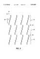
- FIG. 3illustrates an exaggerated depiction of the printing of three swaths of vertical lines, each swath having the length of a column of nozzles on a printbar.
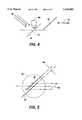
- FIG. 4illustrates a diagrammatic depiction of a sensor scanning a test pattern printed by the printer.
- FIG. 5illustrates an exploded view of the test pattern of FIG. 4 consisting of two overlapping lines.
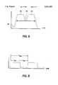
- FIG. 6is a timing diagram showing an output of the sensor of FIG. 4.
- FIG. 7is a block diagram of the electronic circuitry to effect automatic correction of misaligned segmented printbars.
- FIG. 8is a timing diagram showing a fire bank signal which controls the firing of banks of nozzles on a printbar.
- FIG. 9is a flow diagram illustrating a procedure for automatically correcting the alignment of a segmented printbar.
- FIG. 1A typical carriage type multi-color thermal ink jet printing device 10 is shown in FIG. 1.
- a linear array of ink droplet producing channelsis housed in each printhead 12 which can contain an ink supply cartridge therein and which also may be disposable.
- One or more of the printheads 12are replaceably mounted on a reciprocating carriage assembly 14 which reciprocates back and forth in the direction of arrow 16 on guide rails 18.
- the ink droplet producing channelsterminate with orifices or nozzles aligned perpendicularly to the carriage reciprocating direction and parallel to the stepping direction of the recording medium 20 such as paper.
- the stepping direction of the recording medium 20is shown by arrow 22.
- the printheads 12print a swath of information on the stationary recording medium as it moves in a single direction.
- the recording mediumPrior to the carriage and printhead reversing direction, the recording medium is stepped by the printing device 10 a distance equal to the printed swath in the direction of arrow 22. Once a printed swath has been printed in one direction, the printheads 12 move in the opposite direction printing another swath of information. Droplets of ink 24 are expelled from the nozzles and propelled to the recording medium in response to digital data signals received by the printing device controller which, in turn, selectively addresses the individual heating elements located in printhead channels a predetermined distance from the nozzles. Current pulses passing through the printhead heating elements vaporize the ink in contact with the heating elements and temporarily produce vapor bubbles which expel the droplets of ink 24 from the array of nozzles.
- a plurality of printheadsmay be accurately juxtaposed to form a page width array of nozzles.
- the nozzlesare stationary and the paper or recording medium moves passed the page width array of nozzles.
- FIG. 2is a schematic diagram illustrating the basic elements of a printhead integrated circuit necessary to selectively expel ink from the array of linearly aligned nozzles.
- a thermal ink jet integrated circuit or chip 26includes 192 thermal ink jet heating elements 28 which are powered by a 40 volt supply line 30 produced by a power supply 32. Each of the heating elements 28 is additionally coupled to a power MOS FET driver 34 having one side thereof coupled to a ground 36. The power MOS FET drivers 34 energize the heating elements 28 for expelling ink from the nozzles.
- a thermal ink jet chip 26can include any number of ink jet heating elements 28, the present invention is applicable to any number and ink jet heating elements 28, however, eight heating elements 28 are shown in FIG. 2 for illustrative purposes.
- Control of each of the power MOS FET driver 34is accomplished by an and gate 38 having the output thereof coupled to the gate of the driver 34.
- the power supply 32provides an output of greater than 5 volts and typically of 13 volts. This operating voltage for the and gates 38 enables the power MOS FET driver 34 to be turned on harder through the application of a higher gate voltage than would be available from a 5 volt power supply 40 available from the printer 10.
- the thermal ink jet integrated circuit 26controls up to four heaters 28 at a time by using a bidirectional 48 bit pointer shift register 42.
- the shift register 42controls four of the and gates 38 at a time.
- Printingis initiated with a single one bit pointer which begins at the left most side of the bidirectional 48 bit pointer shift register 42 at a line 44 or conductor 44.
- the pointer bitstarts on the left-hand side and propagates to the right-hand side or in the alternative starts on the right-hand side and propagates to the left-hand side depending on the state of a data line 46 at the time a reset line 48 goes high. Bidirectional propagation of the one bit is necessary for bidirectional printing.
- the length of the shift register 42depends on the number of heaters 28 fired together and the total number of heaters 28 in the printhead itself. In the FIG. 2 configuration, 192 nozzles would be fired using a bank of 48 shift registers of four bits each as would be understood by one skilled in the art.
- the shift register 42When the shift register 42 is reset by the reset line 48, four bits of data are loaded from the data line 46 into a four bit shift register 50.
- the four bit shift register 50is shifted by a shift line 52 which receives shift information from a printhead controller as understood by one skilled in the art.
- the four bits of datawhich have been loaded into the four bit register 50, control whether or not a heating element 28 within a block of four heating elements selectively controlled by the shift register 42 will be energized according to the four data bits located in the four bit shift register 50.
- a fire control pulse received from the printhead controller at a fire line 54controls the amount of time that individual heaters 28 are energized. During the cycle of the fire control pulse received over the fire line 54, four new bits of information are loaded into the four bit shift register 50.
- the completion of the fire cycleadvances the shift register 42 pointer bit one position and the fire cycle begins again.
- the shift register 42is reset by the reset line 48.
- a latch 56is used to latch the information from the four bit shift register 50 onto each of the individual MOS FETS 34 for energization.
- each of the individual printheads 12includes a printbar which is divided into 48 segments of four nozzles each.
- the heating elements 28, within each four nozzle segment,are fired simultaneously if all four of the heating elements are selected for energization. After a first bank of four heating elements 28 have been fired simultaneously, then a second bank of four heating elements 28 is fired. Consequently, banks of four heating elements 28 are fired sequentially one after another until all of the heating elements 28 of a printhead have been fired.
- a single printed lineresulting from every nozzle of the printhead, is not actually colinear but rather is formed of small line segments four nozzles long which are slightly staggered with respect to one another.
- the stagger distanceis the distance travelled during the firing period.
- the stagger distanceis relatively small from one bank of four nozzles to the next bank of four nozzles. For instance, at a carriage speed of 15 inches per second and a firing period of 3.2 microseconds, a delay of 48 microinches (1.2 micrometers) results. Multiplying this number by the number of banks of four of the heating elements 28 within a printbar results in a delay or stagger of 57.6 micrometers from the top most nozzle of the printbar to the bottommost nozzle of the printbar. While the stagger distance between individual banks of four heating elements 28 is not particularly noticeable, such error is, however, noticeable at the stitch line or the boundary between two printed swaths.
- FIG. 3illustrates the stagger error in a slightly exaggerated fashion for the purposes of clarity.
- a first swath 58, a second swath 60 and a third swath 62are shown as being printed one beneath the other.
- the swathsare printed from right to left in this FIG. as shown by direction arrow 63.
- Each of the swathsconsists of four banks of four nozzles each.
- a stitch line 64is noticeable between the bottommost nozzle of the printbar printed in the first swath 58 and the topmost nozzle printed by the printbar in the second swath 60.
- a stitchline 66can be seen between the second swath 60 and the third swath 62.
- the last segment printed by a single printbaris electronically delayed by a predetermined amount of time from the time the first segment was printed to try to overcome this particular phenomenon.
- the printbaris typically not mounted at a 90° angle with respect to the process direction but is instead tilted at a small angle to allow for the finite amount of time to print all the segments of a printbar.
- This angleis typically a small angle, usually much less than 1°. Mechanical alignments of this small angle are, however, difficult to obtain. As an example, if a printhead has 32 segments of four heating elements each having a total length of 0.427 inches, the tilt angle necessary to overcome the problem of printing with a segmented printbar is approximately 0.14 degrees. An alignment angle error, slightly exaggerated, is shown as angle 68.
- This electronic methodis especially useful in high speed thermal ink jet printers having longer printheads enabling commensurately higher print speeds which, in turn, causes larger alignment problems due to the longer length of the printhead. While such a method is useful, it is not totally effective since the typically small angle necessary to overcome misalignment is quite difficult to hold to the small fractional tolerance which vary from printhead to printhead due to manufacturing tolerances. In addition, such angles are subject to change with time.
- the present inventionincludes introducing a pre-aligned tilt angle to the printhead to overcompensate for the staggered lines and corrects for the overcompensation by increasing the delay between the firings of the banks of jets. Consequently, the prealigned tilt angle is not subject to close tolerances since any deviation of the tilt angle can be corrected for increasing the delay between firings of the individual banks of jets.
- the present inventionis an electronic method to enhance print quality from printbar types of printers especially those using segmented printbars.
- An electronic autocorrection schemeaddresses the problem of angular misalignment of the printbar and uses a sensor controller actuator subsystem for automatic correction of the misalignment.
- an operatorBy selecting an alignment correction feature of a printer, an operator causes a special diagnostic print pattern to be printed which typically includes lines parallel to the process direction and perpendicular to the scanned direction.
- FIG. 4illustrates a scan direction 70 of a printbar 72, here illustrated as a single line.
- the printbar 72scans in the scan direction 70 and prints a diagnostic test pattern 74 consisting of two single pixel wide lines as shown in greater detail in FIG. 5.
- the circled portion 76 of FIG. 4, illustrated as a single pixel wide line 74,is actually two lines printed in two passes of the printbar 72.
- a first line 78is printed by a first scan of the printbar 72 and a second line 80 is printed subsequent thereto by a second scan of the printbar 72.
- the paper advance mechanism of the printeradvances the paper a partial swath height to cause the first line 78 from the previous scan to slightly overlap the second line 80 along the scanning direction or a given axis.
- a pattern shown in FIG. 5is printed which includes unaligned first line and second line 80.
- the amount of overlap of the first line and second lineis shown as arrowed line 82. Due to the misalignment of the printhead, the first line 78 and the second line 80 are slightly separated by a distance 84.
- the separation distance 84 between the first line 78 and the second line 80must be made as small as possible in subsequent operations.
- incident light 86 from a light source such as a light emitting diodeilluminates the pattern 74 and the separation distance between lines 78 and 80 comprising pattern 74 is calculated.
- a sensoris passed over the line 74 to determine the distance between the first line 78 and the second line 80.
- the sensor 88includes a light source, typically a light emitting diode, and a photodiode for discerning the change in contrast of the pattern, and suitable inexpensive optics. For instance, one pixel of an image input terminal (IIT) scanning bar is acceptable. As shown in FIG. 6, the sensor 88 generates an output over time which indicates the changes in light intensity as the sensor 88 passes from the initial lead edge of the first line 78 to the final trail edge of the second line 80.
- IITimage input terminal
- the signal levelis high when light intensity is low.
- a fairly large amount of light intensityis seen which is shown at 90 in FIG. 6.
- the amount of lightdecreases and is shown here as 92.
- the amount of lightbegins to increase, as shown at 94, until the sensor crosses the second line 80 at 96 wherein the amount of available light has decreased.
- any problems with alignment of the sensorare avoided. For instance, it is possible to print non-overlapping lines and to use a sensing bar having a defined length to determine the distance between the printed non-overlapping lines. Such a system, however, is not preferred, since the sensing bar could misaligned, thereby preventing accurate correction of a misaligned printbar.
- a single point sensorrequires no axial alignment.
- FIG. 7illustrates the electronic circuitry in block diagram form to effect automatic correction of the misaligned segmented printbars.
- the printerincludes a machine control central processing unit (CPU) 97 which controls movement of the printhead carriage and printing by the printhead through a printhead timing control unit 98 which, in turn, controls the timing of the firing of the printbar 72 having the circuit of FIG. 2 when making a print 99.
- CPUcentral processing unit
- a scanning detector 100including the illumination source for generating illumination 86 and the sensor 88 is passed across the printed line 74 as just described.
- the sensor 88generates the output signal of FIG. 6.
- a counter timer 102analyzes the output signal of the sensor 88 to determine the amount of time it took for the scanning detector 100 to cross from the lead edge of the first line to the trail edge of the second line. By knowing the scanning speed of the scanning detection 100 travelling across a printed page and by accumulating statistics on the running average elapsed time to scan across the test pattern, the central processing unit 94 determines the distance between the line 78 and the line 80. The calculated distance is used to correct for the best image using this information.
- the printhead timing control 98which is typically digital logic, is used in printbar printers to produce one or more control signals that govern the data being sent to the printhead.
- the dateincludes a fire bank signal which determines the order in which information is printed and the timing of when that information is printed.
- the fire bank signalis typically a series of periodic pulses or a square wave signal that typically performs two functions: (1) In its active state, its pulse width controls the duration of the firing of the jets within an individual bank. This time period is critical to the successful formation of ink droplets at a given volume and at the printhead speed. This particular parameter remains at a value required by the print process; (2) the time period between pulses determines the relative position of drops on the page by varying the amount of time between the firing of adjacent banks of nozzles.
- FIG. 8illustrates the two states of the fire bank signal.
- T segindicates the entire time period of the fire bank signal.
- the portion labeled T onshows the active state of a first bank signal which controls the duration of the firing of the jets within a bank.
- the segment labeled T offis the period of time which is varied to determine the relative position of the drops on a page. It is this period, T off , that will be adjusted by the central processing unit 97 using an algorithm that performs the operations shown in FIG. 9.
- Step 104the central processing unit 97 initiates printing of the previously described diagnostic pattern at Step 106.
- the CPUmonitors the printing of the diagnostic pattern and at Step 108 determines whether or not the diagnostic pattern has been printed. If not, the CPU continues to monitor whether or not the diagnostic pattern has been printed. Once printed, the counter/timer 102 is reset and armed at step 110. After reset, movement of the scanning detector 100 is initiated by CPU 97 to scan across the diagnostic pattern. Until a line or a first portion of the diagnostic pattern is detected by the sensor 88, the CPU continues to monitor for a line at Step 112. Once a line is detected by the sensor 88, time measurement at Step 114 begins upon sensing the lead edge of the first line 78 and continues at Step 116 until the trailing edge of the line pair has been completed.
- the counter/timer 102receives assignment from the central processing unit 97 indicating completion of its timing of the test pattern.
- a decisionis made to determine whether or not the elapsed time counted by the counter/timer 102 is less than a set point.
- the set pointis a value stored in memory which indicates what amount of correction is necessary to achieve acceptable alignment. If the elapsed time is not less than the set point, then at Step 120 it is determined whether or not this measurement is the first iteration or first measurement of elapsed time. If yes, the diagnostic program returns to Step 108 and continues through Steps 108 through 120 as previously described.
- Step 120If, however, at Step 120, is it is determined that it is not the first iteration, then at Step 122, the newly determined time measurement is compared to the previously determined time measurements and at the time period of the fire bank signal is adjusted at Step 124. Once adjusted, a new diagnostic pattern is printed at Step 108 to determine if an actual improvement has been made in the print quality by recalculating elapsed time. Again, Steps 108 through 118 are completed and if at Step 118 the elapsed time or measured time is now less than the set point then the programs ends at Step 126 to complete the automatic correction.
- the steps described in FIG. 9can be included in an embedded algorithm located in the CPU.
Landscapes
- Engineering & Computer Science (AREA)
- Quality & Reliability (AREA)
- Ink Jet (AREA)
- Particle Formation And Scattering Control In Inkjet Printers (AREA)
Abstract
Description
Claims (27)
Priority Applications (2)
| Application Number | Priority Date | Filing Date | Title |
|---|---|---|---|
| US08/269,319US5534895A (en) | 1994-06-30 | 1994-06-30 | Electronic auto-correction of misaligned segmented printbars |
| JP7155689AJPH0811309A (en) | 1994-06-30 | 1995-06-22 | Electronic automatic correction of segment printing bar in improper alignment |
Applications Claiming Priority (1)
| Application Number | Priority Date | Filing Date | Title |
|---|---|---|---|
| US08/269,319US5534895A (en) | 1994-06-30 | 1994-06-30 | Electronic auto-correction of misaligned segmented printbars |
Publications (1)
| Publication Number | Publication Date |
|---|---|
| US5534895Atrue US5534895A (en) | 1996-07-09 |
Family
ID=23026748
Family Applications (1)
| Application Number | Title | Priority Date | Filing Date |
|---|---|---|---|
| US08/269,319Expired - LifetimeUS5534895A (en) | 1994-06-30 | 1994-06-30 | Electronic auto-correction of misaligned segmented printbars |
Country Status (2)
| Country | Link |
|---|---|
| US (1) | US5534895A (en) |
| JP (1) | JPH0811309A (en) |
Cited By (69)
| Publication number | Priority date | Publication date | Assignee | Title |
|---|---|---|---|---|
| US5751311A (en)* | 1996-03-29 | 1998-05-12 | Xerox Corporation | Hybrid ink jet printer with alignment of scanning printheads to pagewidth printbar |
| EP0869658A2 (en) | 1997-03-31 | 1998-10-07 | Xerox Corporation | Ink jet printer having multiple level grayscale printing |
| US5835108A (en)* | 1996-09-25 | 1998-11-10 | Hewlett-Packard Company | Calibration technique for mis-directed inkjet printhead nozzles |
| US5956055A (en)* | 1997-10-10 | 1999-09-21 | Lexmark International, Inc. | Method of compensating for skewed printing in an ink jet printer |
| EP0978390A1 (en)* | 1998-08-03 | 2000-02-09 | Hewlett-Packard Company | Inkjet printhead calibration |
| EP0982139A1 (en)* | 1998-08-18 | 2000-03-01 | Seiko Epson Corporation | Adjustment of printing position deviation during bidirectional printing |
| US6082911A (en)* | 1997-05-23 | 2000-07-04 | Brother Kogyo Kabushiki Kaisha | Method for judging propriety of printing position and printing apparatus |
| US6084606A (en)* | 1997-03-28 | 2000-07-04 | Canon Kabushiki Kaisha | Printing apparatus and check pattern printing method |
| EP1011976A4 (en)* | 1997-03-28 | 2000-07-05 | Jemtex Ink Jet Printing Ltd | Ink-jet printing apparatus and method |
| US6106095A (en)* | 1997-10-15 | 2000-08-22 | Pitney Bowes Inc. | Mailing machine having registration of multiple arrays of print elements |
| EP1029673A1 (en)* | 1999-02-18 | 2000-08-23 | Hewlett-Packard Company | A correction system for droplet placement errors in the scan axis in inkjet printers |
| US6113231A (en)* | 1998-02-25 | 2000-09-05 | Xerox Corporation | Phase change ink printing architecture suitable for high speed imaging |
| WO2000063022A1 (en)* | 1999-04-15 | 2000-10-26 | Lexmark International, Inc. | Alignment system and method of compensating for skewed printing in an ink jet printer |
| WO2001002184A1 (en)* | 1999-07-01 | 2001-01-11 | Lexmark International, Inc. | Ink jet nozzle fault detection |
| US6196652B1 (en)* | 1998-03-04 | 2001-03-06 | Hewlett-Packard Company | Scanning an inkjet test pattern for different calibration adjustments |
| US6213580B1 (en) | 1998-02-25 | 2001-04-10 | Xerox Corporation | Apparatus and method for automatically aligning print heads |
| GB2358947A (en)* | 2000-02-03 | 2001-08-08 | Hewlett Packard Co | Automatic ink-jet nozzle alignment using test pattern analysis |
| US6322191B1 (en)* | 1997-04-24 | 2001-11-27 | Seiko Epson Corporation | Method of adjusting printing position, printing apparatus using the same, and recording medium having program for the same |
| US6412903B1 (en)* | 2000-09-30 | 2002-07-02 | Samsung Electronics Co., Ltd. | Method of correcting a print error caused by misalignment between chips mounted on an array head of an inkjet printer |
| US20020114008A1 (en)* | 2000-12-07 | 2002-08-22 | Jerry Chen | Method and apparatus for automatic adjustment of printer |
| EP1238814A1 (en) | 2001-03-08 | 2002-09-11 | Agfa-Gevaert | Ink-jet printer equipped for aligning the printheads |
| EP1238813A1 (en) | 2001-03-08 | 2002-09-11 | Agfa-Gevaert | An ink jet printer equipped for aligning the printheads |
| US6457800B1 (en)* | 1997-12-04 | 2002-10-01 | Francotyp Postalia Ag & Co. K.G. | Method for tolerance compensation in an ink jet print head |
| US6478401B1 (en) | 2001-07-06 | 2002-11-12 | Lexmark International, Inc. | Method for determining vertical misalignment between printer print heads |
| US6485124B1 (en) | 2001-07-02 | 2002-11-26 | Lexmark International, Inc. | Optical alignment method and detector |
| US6488353B1 (en)* | 1999-06-18 | 2002-12-03 | Sharp Kabushiki Kaisha | Image forming apparatus diagnosing print head and optical system conditions based on printed test pattern |
| US6494563B2 (en)* | 1997-12-25 | 2002-12-17 | Canon Kabushiki Kaisha | Ink jet element substrate and ink jet head that employs the substrate, and ink jet apparatus on which the head is mounted |
| US6561613B2 (en) | 2001-10-05 | 2003-05-13 | Lexmark International, Inc. | Method for determining printhead misalignment of a printer |
| US6565180B2 (en)* | 2000-02-15 | 2003-05-20 | Benq Corporation | Ink jet printer with a compensation function for malfunctioning nozzles |
| US6582055B1 (en) | 2001-08-07 | 2003-06-24 | Lexmark International, Inc. | Method for operating a printer having vertically offset printheads |
| US6588872B2 (en) | 2001-04-06 | 2003-07-08 | Lexmark International, Inc. | Electronic skew adjustment in an ink jet printer |
| US6604808B2 (en) | 2001-07-03 | 2003-08-12 | Lexmark International, Inc. | Method for determining the skew of a printhead of a printer |
| US6607260B1 (en)* | 1998-12-21 | 2003-08-19 | Canon Kabushiki Kaisha | Recording apparatus and recording position correcting method |
| US6616261B2 (en) | 2001-07-18 | 2003-09-09 | Lexmark International, Inc. | Automatic bi-directional alignment method and sensor for an ink jet printer |
| US6629747B1 (en) | 2002-06-20 | 2003-10-07 | Lexmark International, Inc. | Method for determining ink drop velocity of carrier-mounted printhead |
| US6655777B2 (en) | 2001-07-18 | 2003-12-02 | Lexmark International, Inc. | Automatic horizontal and vertical head-to-head alignment method and sensor for an ink jet printer |
| US6684773B2 (en) | 2002-03-21 | 2004-02-03 | Lexmark International, Inc. | Target and algorithm for color laser printhead alignment |
| EP1413435A1 (en)* | 2002-10-22 | 2004-04-28 | Samsung Electronics Co., Ltd. | Firing nozzles of a printer |
| US20040085378A1 (en)* | 2002-10-31 | 2004-05-06 | Sievert Otto K. | Printing apparatus calibration |
| US6746107B2 (en) | 2001-10-31 | 2004-06-08 | Hewlett-Packard Development Company, L.P. | Inkjet printhead having ink feed channels defined by thin-film structure and orifice layer |
| US20050018006A1 (en)* | 2003-06-27 | 2005-01-27 | Samsung Electronics Co., Ltd. | Method of determining missing nozzles in an inkjet printer |
| US20050073539A1 (en)* | 2003-10-07 | 2005-04-07 | Mcgarry Mark | Ink placement adjustment |
| US6890047B2 (en)* | 2000-03-13 | 2005-05-10 | Canon Kabushiki Kaisha | Printing apparatus and printing method |
| US6932453B2 (en)* | 2001-10-31 | 2005-08-23 | Hewlett-Packard Development Company, L.P. | Inkjet printhead assembly having very high drop rate generation |
| US20050243114A1 (en)* | 1999-05-25 | 2005-11-03 | Silverbrook Research Pty Ltd | Synchronization of printing and print media in a printer module |
| US20060067592A1 (en)* | 2004-05-27 | 2006-03-30 | Walmsley Simon R | Configurable image processor |
| US20060066658A1 (en)* | 2004-09-30 | 2006-03-30 | Olson Stephen T | Methods for determining unidirectional print direction for improved quality |
| US20060132525A1 (en)* | 2004-05-27 | 2006-06-22 | Silverbrook Research Pty Ltd | Printer controller for at least partially compensating for erroneous rotational displacement |
| US20060139380A1 (en)* | 2004-05-27 | 2006-06-29 | Silverbrook Research Pty Ltd | Printer controller for causing expulsion of ink from nozzles in groups, starting at outside nozzles of groups |
| US20060164454A1 (en)* | 2004-05-27 | 2006-07-27 | Silverbrook Research Pty Ltd | Method for at least partially compensating for errors in ink dot placement due to erroneous rotational displacement |
| US20060164451A1 (en)* | 2004-05-27 | 2006-07-27 | Silverbrook Research Pty Ltd | Method of expelling ink from nozzles in groups, alternately, starting at outside nozzles of each group |
| US20070064056A1 (en)* | 2000-12-07 | 2007-03-22 | Silverbrook Research Pty Ltd | Printhead module with a micro-electromechanical integrated circuit configured to eject ink |
| US20070064057A1 (en)* | 1999-12-09 | 2007-03-22 | Silverbrook Research Pty Ltd | Printhead module for an inkjet printhead assembly incorporating a printhead integrated circuit |
| DE10211895B4 (en)* | 2001-03-26 | 2007-07-05 | Hewlett-Packard Development Co., L.P., Houston | Pen alignment using a color sensor |
| US20080117249A1 (en)* | 2006-11-17 | 2008-05-22 | Childers Winthrop D | Misfiring print nozzle compensation |
| CN100396490C (en)* | 2001-04-02 | 2008-06-25 | 明基电通股份有限公司 | ink jet printer with nozzle abnormality compensation function |
| US20090079781A1 (en)* | 2007-09-26 | 2009-03-26 | Fuji Xerox Co., Ltd. | Print control apparatus |
| US20100149555A1 (en)* | 2008-12-16 | 2010-06-17 | Canon Kabushiki Kaisha | Method For Generating Alignment Marks |
| US20100149247A1 (en)* | 2008-12-16 | 2010-06-17 | Canon Kabushiki Kaisha | Nozzle functionality detection of inkjet printers |
| US20100231625A1 (en)* | 2004-05-27 | 2010-09-16 | Silverbrook Research Pty Ltd | Printhead having controlled nozzle firing grouping |
| US20100250942A1 (en)* | 2004-05-27 | 2010-09-30 | Silverbrook Research Pty Ltd | System for enabling authenticated communication between entities |
| US20100271439A1 (en)* | 2004-05-27 | 2010-10-28 | Silverbrook Research Pty Ltd. | Printhead integrated circuit with thermally sensing heater elements |
| US20100277527A1 (en)* | 2004-05-27 | 2010-11-04 | Silverbrook Research Pty Ltd. | Printer having printhead with multiple controllers |
| US7914107B2 (en) | 2004-05-27 | 2011-03-29 | Silverbrook Research Pty Ltd | Printer incorporating multiple synchronizing printer controllers |
| US8363261B1 (en)* | 2008-08-13 | 2013-01-29 | Marvell International Ltd. | Methods, software, circuits and apparatuses for detecting a malfunction in an imaging device |
| CN104723676A (en)* | 2013-12-20 | 2015-06-24 | 佳能株式会社 | Liquid ejection apparatus and sensor unit |
| EP3099488A4 (en)* | 2014-01-30 | 2017-10-11 | Hewlett-Packard Development Company, L.P. | Adjusting the firing times of a number of nozzles |
| US9908323B2 (en) | 2012-07-10 | 2018-03-06 | Hewlett-Packard Development Company, L.P. | Printing system control |
| US12240230B2 (en) | 2020-09-25 | 2025-03-04 | Hewlett-Packard Development Company, L.P. | Fluidic dies |
Families Citing this family (2)
| Publication number | Priority date | Publication date | Assignee | Title |
|---|---|---|---|---|
| JP3539108B2 (en)* | 1997-02-04 | 2004-07-07 | セイコーエプソン株式会社 | Print quality adjustment method and printing method and apparatus |
| KR20060084127A (en) | 2005-01-17 | 2006-07-24 | 삼성전자주식회사 | Alignment adjustment method and apparatus of an image forming apparatus |
Citations (9)
| Publication number | Priority date | Publication date | Assignee | Title |
|---|---|---|---|---|
| US4709245A (en)* | 1986-12-22 | 1987-11-24 | Eastman Kodak Company | Ink jet printer for cooperatively printing with a plurality of insertable print/cartridges |
| US4818129A (en)* | 1986-10-09 | 1989-04-04 | Oki Electric Industry Co., Ltd. | Method for correcting bidirectional printing alignment of a serial dot printer |
| US5049898A (en)* | 1989-03-20 | 1991-09-17 | Hewlett-Packard Company | Printhead having memory element |
| US5069556A (en)* | 1989-03-17 | 1991-12-03 | Hitachi, Ltd. | Method for correcting drift of printing position and printing apparatus for practising the same |
| US5250956A (en)* | 1991-10-31 | 1993-10-05 | Hewlett-Packard Company | Print cartridge bidirectional alignment in carriage axis |
| US5289208A (en)* | 1991-10-31 | 1994-02-22 | Hewlett-Packard Company | Automatic print cartridge alignment sensor system |
| US5297017A (en)* | 1991-10-31 | 1994-03-22 | Hewlett-Packard Company | Print cartridge alignment in paper axis |
| US5430469A (en)* | 1991-06-05 | 1995-07-04 | Canon Kabushiki Kaisha | Tone recording method using ink recording head |
| US5442383A (en)* | 1992-04-22 | 1995-08-15 | Fuji Xerox Co., Ltd. | Ink jet printer with a device for determining a printing interval |
- 1994
- 1994-06-30USUS08/269,319patent/US5534895A/ennot_activeExpired - Lifetime
- 1995
- 1995-06-22JPJP7155689Apatent/JPH0811309A/ennot_activeWithdrawn
Patent Citations (9)
| Publication number | Priority date | Publication date | Assignee | Title |
|---|---|---|---|---|
| US4818129A (en)* | 1986-10-09 | 1989-04-04 | Oki Electric Industry Co., Ltd. | Method for correcting bidirectional printing alignment of a serial dot printer |
| US4709245A (en)* | 1986-12-22 | 1987-11-24 | Eastman Kodak Company | Ink jet printer for cooperatively printing with a plurality of insertable print/cartridges |
| US5069556A (en)* | 1989-03-17 | 1991-12-03 | Hitachi, Ltd. | Method for correcting drift of printing position and printing apparatus for practising the same |
| US5049898A (en)* | 1989-03-20 | 1991-09-17 | Hewlett-Packard Company | Printhead having memory element |
| US5430469A (en)* | 1991-06-05 | 1995-07-04 | Canon Kabushiki Kaisha | Tone recording method using ink recording head |
| US5250956A (en)* | 1991-10-31 | 1993-10-05 | Hewlett-Packard Company | Print cartridge bidirectional alignment in carriage axis |
| US5289208A (en)* | 1991-10-31 | 1994-02-22 | Hewlett-Packard Company | Automatic print cartridge alignment sensor system |
| US5297017A (en)* | 1991-10-31 | 1994-03-22 | Hewlett-Packard Company | Print cartridge alignment in paper axis |
| US5442383A (en)* | 1992-04-22 | 1995-08-15 | Fuji Xerox Co., Ltd. | Ink jet printer with a device for determining a printing interval |
Cited By (113)
| Publication number | Priority date | Publication date | Assignee | Title |
|---|---|---|---|---|
| US5751311A (en)* | 1996-03-29 | 1998-05-12 | Xerox Corporation | Hybrid ink jet printer with alignment of scanning printheads to pagewidth printbar |
| US5835108A (en)* | 1996-09-25 | 1998-11-10 | Hewlett-Packard Company | Calibration technique for mis-directed inkjet printhead nozzles |
| EP1011976A4 (en)* | 1997-03-28 | 2000-07-05 | Jemtex Ink Jet Printing Ltd | Ink-jet printing apparatus and method |
| US6084606A (en)* | 1997-03-28 | 2000-07-04 | Canon Kabushiki Kaisha | Printing apparatus and check pattern printing method |
| EP0869658A2 (en) | 1997-03-31 | 1998-10-07 | Xerox Corporation | Ink jet printer having multiple level grayscale printing |
| US6322191B1 (en)* | 1997-04-24 | 2001-11-27 | Seiko Epson Corporation | Method of adjusting printing position, printing apparatus using the same, and recording medium having program for the same |
| US6082911A (en)* | 1997-05-23 | 2000-07-04 | Brother Kogyo Kabushiki Kaisha | Method for judging propriety of printing position and printing apparatus |
| US5956055A (en)* | 1997-10-10 | 1999-09-21 | Lexmark International, Inc. | Method of compensating for skewed printing in an ink jet printer |
| US6106095A (en)* | 1997-10-15 | 2000-08-22 | Pitney Bowes Inc. | Mailing machine having registration of multiple arrays of print elements |
| US6457800B1 (en)* | 1997-12-04 | 2002-10-01 | Francotyp Postalia Ag & Co. K.G. | Method for tolerance compensation in an ink jet print head |
| US6705692B2 (en) | 1997-12-25 | 2004-03-16 | Canon Kabushiki Kaisha | Ink jet element substrate and ink jet head that employs the substrate, and ink jet apparatus on which the head is mounted |
| US6494563B2 (en)* | 1997-12-25 | 2002-12-17 | Canon Kabushiki Kaisha | Ink jet element substrate and ink jet head that employs the substrate, and ink jet apparatus on which the head is mounted |
| US6113231A (en)* | 1998-02-25 | 2000-09-05 | Xerox Corporation | Phase change ink printing architecture suitable for high speed imaging |
| US6213580B1 (en) | 1998-02-25 | 2001-04-10 | Xerox Corporation | Apparatus and method for automatically aligning print heads |
| US6196652B1 (en)* | 1998-03-04 | 2001-03-06 | Hewlett-Packard Company | Scanning an inkjet test pattern for different calibration adjustments |
| US6076915A (en)* | 1998-08-03 | 2000-06-20 | Hewlett-Packard Company | Inkjet printhead calibration |
| EP0978390A1 (en)* | 1998-08-03 | 2000-02-09 | Hewlett-Packard Company | Inkjet printhead calibration |
| US6196736B1 (en) | 1998-08-18 | 2001-03-06 | Seiko Epson Corporation | Adjustment of printing position deviation during bidirectional printing |
| EP0982139A1 (en)* | 1998-08-18 | 2000-03-01 | Seiko Epson Corporation | Adjustment of printing position deviation during bidirectional printing |
| US6607260B1 (en)* | 1998-12-21 | 2003-08-19 | Canon Kabushiki Kaisha | Recording apparatus and recording position correcting method |
| EP1029673A1 (en)* | 1999-02-18 | 2000-08-23 | Hewlett-Packard Company | A correction system for droplet placement errors in the scan axis in inkjet printers |
| US6364447B1 (en) | 1999-02-18 | 2002-04-02 | Hewlett-Packard Company | Correction system for droplet placement errors in the scan axis in inkjet printers |
| US6345876B1 (en) | 1999-03-05 | 2002-02-12 | Hewlett-Packard Company | Peak-valley finder process for scanned optical relative displacement measurements |
| WO2000063022A1 (en)* | 1999-04-15 | 2000-10-26 | Lexmark International, Inc. | Alignment system and method of compensating for skewed printing in an ink jet printer |
| US6281908B1 (en)* | 1999-04-15 | 2001-08-28 | Lexmark International, Inc. | Alignment system and method of compensating for skewed printing in an ink jet printer |
| US20050243114A1 (en)* | 1999-05-25 | 2005-11-03 | Silverbrook Research Pty Ltd | Synchronization of printing and print media in a printer module |
| US6488353B1 (en)* | 1999-06-18 | 2002-12-03 | Sharp Kabushiki Kaisha | Image forming apparatus diagnosing print head and optical system conditions based on printed test pattern |
| WO2001002184A1 (en)* | 1999-07-01 | 2001-01-11 | Lexmark International, Inc. | Ink jet nozzle fault detection |
| US8376519B2 (en) | 1999-12-09 | 2013-02-19 | Zamtec Ltd | Printhead having assembly of printhead modules |
| US7708380B2 (en)* | 1999-12-09 | 2010-05-04 | Silverbrook Research Pty Ltd | Printhead module for an inkjet printhead assembly incorporating a printhead integrated circuit |
| US20070064057A1 (en)* | 1999-12-09 | 2007-03-22 | Silverbrook Research Pty Ltd | Printhead module for an inkjet printhead assembly incorporating a printhead integrated circuit |
| GB2358947A (en)* | 2000-02-03 | 2001-08-08 | Hewlett Packard Co | Automatic ink-jet nozzle alignment using test pattern analysis |
| US6565180B2 (en)* | 2000-02-15 | 2003-05-20 | Benq Corporation | Ink jet printer with a compensation function for malfunctioning nozzles |
| US6890047B2 (en)* | 2000-03-13 | 2005-05-10 | Canon Kabushiki Kaisha | Printing apparatus and printing method |
| US6412903B1 (en)* | 2000-09-30 | 2002-07-02 | Samsung Electronics Co., Ltd. | Method of correcting a print error caused by misalignment between chips mounted on an array head of an inkjet printer |
| US20020114008A1 (en)* | 2000-12-07 | 2002-08-22 | Jerry Chen | Method and apparatus for automatic adjustment of printer |
| US20070064056A1 (en)* | 2000-12-07 | 2007-03-22 | Silverbrook Research Pty Ltd | Printhead module with a micro-electromechanical integrated circuit configured to eject ink |
| US20090201342A1 (en)* | 2000-12-07 | 2009-08-13 | Silverbrook Research Pty Ltd | Printhead Module For A Inkjet Printhead Assembly |
| US8020968B2 (en) | 2000-12-07 | 2011-09-20 | Silverbrook Research Pty Ltd | Printhead module for a inkjet printhead assembly |
| US7042592B2 (en)* | 2000-12-07 | 2006-05-09 | Lite-On Technology Corporation | Method and apparatus for automatic adjustment of printer |
| US8500249B2 (en) | 2000-12-07 | 2013-08-06 | Zamtec Ltd | Printhead module for an inkjet printhead assembly |
| US7530669B2 (en)* | 2000-12-07 | 2009-05-12 | Silverbrook Research Pty Ltd | Printhead module with a micro-electromechanical integrated circuit configured to eject ink |
| EP1238813A1 (en) | 2001-03-08 | 2002-09-11 | Agfa-Gevaert | An ink jet printer equipped for aligning the printheads |
| EP1238814A1 (en) | 2001-03-08 | 2002-09-11 | Agfa-Gevaert | Ink-jet printer equipped for aligning the printheads |
| DE10211895B4 (en)* | 2001-03-26 | 2007-07-05 | Hewlett-Packard Development Co., L.P., Houston | Pen alignment using a color sensor |
| CN100396490C (en)* | 2001-04-02 | 2008-06-25 | 明基电通股份有限公司 | ink jet printer with nozzle abnormality compensation function |
| US6588872B2 (en) | 2001-04-06 | 2003-07-08 | Lexmark International, Inc. | Electronic skew adjustment in an ink jet printer |
| US6485124B1 (en) | 2001-07-02 | 2002-11-26 | Lexmark International, Inc. | Optical alignment method and detector |
| US6604808B2 (en) | 2001-07-03 | 2003-08-12 | Lexmark International, Inc. | Method for determining the skew of a printhead of a printer |
| US6478401B1 (en) | 2001-07-06 | 2002-11-12 | Lexmark International, Inc. | Method for determining vertical misalignment between printer print heads |
| US6616261B2 (en) | 2001-07-18 | 2003-09-09 | Lexmark International, Inc. | Automatic bi-directional alignment method and sensor for an ink jet printer |
| US6655777B2 (en) | 2001-07-18 | 2003-12-02 | Lexmark International, Inc. | Automatic horizontal and vertical head-to-head alignment method and sensor for an ink jet printer |
| US6582055B1 (en) | 2001-08-07 | 2003-06-24 | Lexmark International, Inc. | Method for operating a printer having vertically offset printheads |
| US6561613B2 (en) | 2001-10-05 | 2003-05-13 | Lexmark International, Inc. | Method for determining printhead misalignment of a printer |
| US6932453B2 (en)* | 2001-10-31 | 2005-08-23 | Hewlett-Packard Development Company, L.P. | Inkjet printhead assembly having very high drop rate generation |
| US6746107B2 (en) | 2001-10-31 | 2004-06-08 | Hewlett-Packard Development Company, L.P. | Inkjet printhead having ink feed channels defined by thin-film structure and orifice layer |
| US6684773B2 (en) | 2002-03-21 | 2004-02-03 | Lexmark International, Inc. | Target and algorithm for color laser printhead alignment |
| US6629747B1 (en) | 2002-06-20 | 2003-10-07 | Lexmark International, Inc. | Method for determining ink drop velocity of carrier-mounted printhead |
| EP1413435A1 (en)* | 2002-10-22 | 2004-04-28 | Samsung Electronics Co., Ltd. | Firing nozzles of a printer |
| US6883892B2 (en) | 2002-10-31 | 2005-04-26 | Hewlett-Packard Development Company, L.P. | Printing apparatus calibration |
| US20040085378A1 (en)* | 2002-10-31 | 2004-05-06 | Sievert Otto K. | Printing apparatus calibration |
| US20050018006A1 (en)* | 2003-06-27 | 2005-01-27 | Samsung Electronics Co., Ltd. | Method of determining missing nozzles in an inkjet printer |
| US20050073539A1 (en)* | 2003-10-07 | 2005-04-07 | Mcgarry Mark | Ink placement adjustment |
| US20060139380A1 (en)* | 2004-05-27 | 2006-06-29 | Silverbrook Research Pty Ltd | Printer controller for causing expulsion of ink from nozzles in groups, starting at outside nozzles of groups |
| US20100250942A1 (en)* | 2004-05-27 | 2010-09-30 | Silverbrook Research Pty Ltd | System for enabling authenticated communication between entities |
| US20060067592A1 (en)* | 2004-05-27 | 2006-03-30 | Walmsley Simon R | Configurable image processor |
| US7377609B2 (en)* | 2004-05-27 | 2008-05-27 | Silverbrook Research Pty Ltd | Printer controller for at least partially compensating for erroneous rotational displacement |
| US20080129768A1 (en)* | 2004-05-27 | 2008-06-05 | Silverbrook Research Pty Ltd | Printer Controller For Nozzle Displacement Correction |
| US7374266B2 (en)* | 2004-05-27 | 2008-05-20 | Silverbrook Research Pty Ltd | Method for at least partially compensating for errors in ink dot placement due to erroneous rotational displacement |
| US7427117B2 (en)* | 2004-05-27 | 2008-09-23 | Silverbrook Research Pty Ltd | Method of expelling ink from nozzles in groups, alternately, starting at outside nozzles of each group |
| US20080266337A1 (en)* | 2004-05-27 | 2008-10-30 | Silverbrook Research Pty Ltd | Printer system having controller with correction for nozzle displacement |
| US8308274B2 (en) | 2004-05-27 | 2012-11-13 | Zamtec Limited | Printhead integrated circuit with thermally sensing heater elements |
| US7472978B2 (en) | 2004-05-27 | 2009-01-06 | Silverbrook Research Pty Ltd | Printer controller for nozzle displacement correction |
| US8282184B2 (en) | 2004-05-27 | 2012-10-09 | Zamtec Limited | Print engine controller employing accumulative correction factor in pagewidth printhead |
| US8123318B2 (en) | 2004-05-27 | 2012-02-28 | Silverbrook Research Pty Ltd | Printhead having controlled nozzle firing grouping |
| US7549715B2 (en)* | 2004-05-27 | 2009-06-23 | Silverbrook Research Pty Ltd | Printer controller for causing expulsion of ink from nozzles in groups, starting at outside nozzles of groups |
| US7556331B2 (en) | 2004-05-27 | 2009-07-07 | Silverbrook Research Pty Ltd | Inkjet printer having nozzle displacement correction |
| US20060164451A1 (en)* | 2004-05-27 | 2006-07-27 | Silverbrook Research Pty Ltd | Method of expelling ink from nozzles in groups, alternately, starting at outside nozzles of each group |
| US20090213155A1 (en)* | 2004-05-27 | 2009-08-27 | Silverbrook Research Pty Ltd | Printhead having sequenced nozzle firing on integrated circuit |
| US20060132525A1 (en)* | 2004-05-27 | 2006-06-22 | Silverbrook Research Pty Ltd | Printer controller for at least partially compensating for erroneous rotational displacement |
| US20090295855A1 (en)* | 2004-05-27 | 2009-12-03 | Silverbrook Research Pty Ltd | Printer Having Nozzle Displacement Correction |
| US20060164454A1 (en)* | 2004-05-27 | 2006-07-27 | Silverbrook Research Pty Ltd | Method for at least partially compensating for errors in ink dot placement due to erroneous rotational displacement |
| US8007063B2 (en) | 2004-05-27 | 2011-08-30 | Silverbrook Research Pty Ltd | Printer having printhead with multiple controllers |
| US7980647B2 (en) | 2004-05-27 | 2011-07-19 | Silverbrook Research Pty Ltd | Printer having nozzle displacement correction |
| US7740334B2 (en) | 2004-05-27 | 2010-06-22 | Silverbrook Research Pty Ltd | Printer system having controller with correction for nozzle displacement |
| US20100231625A1 (en)* | 2004-05-27 | 2010-09-16 | Silverbrook Research Pty Ltd | Printhead having controlled nozzle firing grouping |
| US7802862B2 (en) | 2004-05-27 | 2010-09-28 | Kia Silverbrook | Printhead having sequenced nozzle firing on integrated circuit |
| US20100245429A1 (en)* | 2004-05-27 | 2010-09-30 | Silverbrook Research Pty Ltd | Print engine controller employing accumulative correction factor in pagewidth printhead |
| US7971949B2 (en) | 2004-05-27 | 2011-07-05 | Silverbrook Research Pty Ltd | Printer controller for correction of rotationally displaced printhead |
| US20100271439A1 (en)* | 2004-05-27 | 2010-10-28 | Silverbrook Research Pty Ltd. | Printhead integrated circuit with thermally sensing heater elements |
| US20100277527A1 (en)* | 2004-05-27 | 2010-11-04 | Silverbrook Research Pty Ltd. | Printer having printhead with multiple controllers |
| US7914107B2 (en) | 2004-05-27 | 2011-03-29 | Silverbrook Research Pty Ltd | Printer incorporating multiple synchronizing printer controllers |
| US7467843B2 (en) | 2004-09-30 | 2008-12-23 | Lexmark International, Inc. | Methods for determining unidirectional print direction for improved print quality |
| US7374269B2 (en) | 2004-09-30 | 2008-05-20 | Lexmark International, Inc. | Methods for determining unidirectional print direction for improved quality |
| US20070252862A1 (en)* | 2004-09-30 | 2007-11-01 | Lexmark International, Inc. | Methods For Determining Unidirectional Print Direction For Improved Print Quality |
| US20060066658A1 (en)* | 2004-09-30 | 2006-03-30 | Olson Stephen T | Methods for determining unidirectional print direction for improved quality |
| US20080117249A1 (en)* | 2006-11-17 | 2008-05-22 | Childers Winthrop D | Misfiring print nozzle compensation |
| US7607752B2 (en) | 2006-11-17 | 2009-10-27 | Hewlett-Packard Development Company, L.P. | Misfiring print nozzle compensation |
| US8444244B2 (en)* | 2007-09-26 | 2013-05-21 | Fuji Xerox Co., Ltd. | Print control apparatus |
| US20090079781A1 (en)* | 2007-09-26 | 2009-03-26 | Fuji Xerox Co., Ltd. | Print control apparatus |
| US8363261B1 (en)* | 2008-08-13 | 2013-01-29 | Marvell International Ltd. | Methods, software, circuits and apparatuses for detecting a malfunction in an imaging device |
| US8442352B2 (en) | 2008-12-16 | 2013-05-14 | Canon Kabushiki Kaisha | Method for generating alignment marks |
| US20100149555A1 (en)* | 2008-12-16 | 2010-06-17 | Canon Kabushiki Kaisha | Method For Generating Alignment Marks |
| US20100149247A1 (en)* | 2008-12-16 | 2010-06-17 | Canon Kabushiki Kaisha | Nozzle functionality detection of inkjet printers |
| US9908323B2 (en) | 2012-07-10 | 2018-03-06 | Hewlett-Packard Development Company, L.P. | Printing system control |
| US10350880B2 (en) | 2012-07-10 | 2019-07-16 | Hewlett-Packard Development Company, L.P. | Printing system control |
| US20150174894A1 (en)* | 2013-12-20 | 2015-06-25 | Canon Kabushiki Kaisha | Liquid ejection apparatus and sensor unit |
| CN104723676B (en)* | 2013-12-20 | 2016-11-23 | 佳能株式会社 | Liquid discharge apparatus and sensor unit |
| US9156252B2 (en)* | 2013-12-20 | 2015-10-13 | Canon Kabushiki Kaisha | Liquid ejection apparatus and sensor unit |
| CN104723676A (en)* | 2013-12-20 | 2015-06-24 | 佳能株式会社 | Liquid ejection apparatus and sensor unit |
| EP3099488A4 (en)* | 2014-01-30 | 2017-10-11 | Hewlett-Packard Development Company, L.P. | Adjusting the firing times of a number of nozzles |
| US9849671B2 (en) | 2014-01-30 | 2017-12-26 | Hewlett-Packard Development Company, L.P. | Adjusting the firing times of a number of nozzles |
| US12240230B2 (en) | 2020-09-25 | 2025-03-04 | Hewlett-Packard Development Company, L.P. | Fluidic dies |
Also Published As
| Publication number | Publication date |
|---|---|
| JPH0811309A (en) | 1996-01-16 |
Similar Documents
| Publication | Publication Date | Title |
|---|---|---|
| US5534895A (en) | Electronic auto-correction of misaligned segmented printbars | |
| US6367903B1 (en) | Alignment of ink dots in an inkjet printer | |
| US6547360B2 (en) | Locating method of an optical sensor, an adjustment method of dot printing position using the optical sensor, and a printing apparatus | |
| JP3382526B2 (en) | Printing apparatus and ink discharge state detection method | |
| US6310637B1 (en) | Method of printing test pattern and printing apparatus for the same | |
| US6863361B2 (en) | Method to correct for malfunctioning ink ejection elements in a single pass print mode | |
| US4509057A (en) | Automatic calibration of drop-on-demand ink jet ejector | |
| US5790150A (en) | Method for controlling an ink jet printer in a multipass printing mode | |
| US8523310B2 (en) | Printing apparatus and printing method | |
| JP4323580B2 (en) | Printing apparatus and head driving method thereof | |
| US6607260B1 (en) | Recording apparatus and recording position correcting method | |
| JPH11291477A (en) | Printing equipment | |
| EP0767061B1 (en) | Liquid ink printer for producing high resolution images | |
| US20070002090A1 (en) | Inkjet recording apparatus having an adjusting mechanism for adjusting moving of a recording medium | |
| US20100156977A1 (en) | Ink jet printing apparatus and printing method | |
| JP4006786B2 (en) | Test dot recording method and printer | |
| US5442383A (en) | Ink jet printer with a device for determining a printing interval | |
| US20210300031A1 (en) | Inkjet printing apparatus and inkjet printing method | |
| US6174037B1 (en) | Multiple pass ink jet printer with optimized power supply | |
| US6193350B1 (en) | Method and apparatus for dynamically aligning a printer printhead | |
| US6918644B2 (en) | Image recording apparatus | |
| US7163275B2 (en) | Methods and apparatus for an automatic fluid ejector alignment and performance system | |
| US5803628A (en) | Printing apparatus including encoder pending | |
| US6439686B2 (en) | Ink jet printer having apparatus for reducing systematic print quality defects | |
| US7083246B2 (en) | Electronic tilt adjustment in fluid-jet fluid ejecting heads |
Legal Events
| Date | Code | Title | Description |
|---|---|---|---|
| AS | Assignment | Owner name:XEROX CORPORATION, CONNECTICUT Free format text:ASSIGNMENT OF ASSIGNORS INTEREST;ASSIGNORS:LINDENFELSER, WILLIAM M.;DONAHUE, FREDERICK A.;REEL/FRAME:007071/0751 Effective date:19940627 | |
| STCF | Information on status: patent grant | Free format text:PATENTED CASE | |
| FPAY | Fee payment | Year of fee payment:4 | |
| AS | Assignment | Owner name:BANK ONE, NA, AS ADMINISTRATIVE AGENT, ILLINOIS Free format text:SECURITY INTEREST;ASSIGNOR:XEROX CORPORATION;REEL/FRAME:013153/0001 Effective date:20020621 | |
| AS | Assignment | Owner name:JPMORGAN CHASE BANK, AS COLLATERAL AGENT, TEXAS Free format text:SECURITY AGREEMENT;ASSIGNOR:XEROX CORPORATION;REEL/FRAME:015134/0476 Effective date:20030625 Owner name:JPMORGAN CHASE BANK, AS COLLATERAL AGENT,TEXAS Free format text:SECURITY AGREEMENT;ASSIGNOR:XEROX CORPORATION;REEL/FRAME:015134/0476 Effective date:20030625 | |
| REMI | Maintenance fee reminder mailed | ||
| FPAY | Fee payment | Year of fee payment:8 | |
| SULP | Surcharge for late payment | Year of fee payment:7 | |
| FEPP | Fee payment procedure | Free format text:PAYOR NUMBER ASSIGNED (ORIGINAL EVENT CODE: ASPN); ENTITY STATUS OF PATENT OWNER: LARGE ENTITY | |
| AS | Assignment | Owner name:SAMSUNG ELECTRONICS CO., LTD., KOREA, REPUBLIC OF Free format text:ASSIGNMENT OF ASSIGNORS INTEREST;ASSIGNOR:XEROX CORPORATION;REEL/FRAME:015687/0884 Effective date:20050113 | |
| AS | Assignment | Owner name:XEROX CORPORATION, CONNECTICUT Free format text:RELEASE OF PATENTS;ASSIGNOR:JP MORGAN CHASE BANK, N.A.;REEL/FRAME:016408/0016 Effective date:20050330 | |
| FPAY | Fee payment | Year of fee payment:12 | |
| AS | Assignment | Owner name:XEROX CORPORATION, NEW YORK Free format text:RELEASE OF SECURITY INTEREST;ASSIGNOR:BANK ONE, NA;REEL/FRAME:033100/0582 Effective date:20030625 | |
| AS | Assignment | Owner name:XEROX CORPORATION, NEW YORK Free format text:RELEASE BY SECURED PARTY;ASSIGNOR:JPMORGAN CHASE BANK, N.A.;REEL/FRAME:034474/0560 Effective date:20061204 | |
| AS | Assignment | Owner name:XEROX CORPORATION, CONNECTICUT Free format text:RELEASE BY SECURED PARTY;ASSIGNOR:JPMORGAN CHASE BANK, N.A. AS SUCCESSOR-IN-INTEREST ADMINISTRATIVE AGENT AND COLLATERAL AGENT TO JPMORGAN CHASE BANK;REEL/FRAME:066728/0193 Effective date:20220822 |