US5534826A - Oscillator with increased reliability start up - Google Patents
Oscillator with increased reliability start upDownload PDFInfo
- Publication number
- US5534826A US5534826AUS08/327,778US32777894AUS5534826AUS 5534826 AUS5534826 AUS 5534826AUS 32777894 AUS32777894 AUS 32777894AUS 5534826 AUS5534826 AUS 5534826A
- Authority
- US
- United States
- Prior art keywords
- input
- oscillator
- oscillation
- impedance
- amplifier
- Prior art date
- Legal status (The legal status is an assumption and is not a legal conclusion. Google has not performed a legal analysis and makes no representation as to the accuracy of the status listed.)
- Expired - Lifetime
Links
Images

Classifications
- H—ELECTRICITY
- H03—ELECTRONIC CIRCUITRY
- H03B—GENERATION OF OSCILLATIONS, DIRECTLY OR BY FREQUENCY-CHANGING, BY CIRCUITS EMPLOYING ACTIVE ELEMENTS WHICH OPERATE IN A NON-SWITCHING MANNER; GENERATION OF NOISE BY SUCH CIRCUITS
- H03B5/00—Generation of oscillations using amplifier with regenerative feedback from output to input
- H03B5/30—Generation of oscillations using amplifier with regenerative feedback from output to input with frequency-determining element being electromechanical resonator
- H03B5/32—Generation of oscillations using amplifier with regenerative feedback from output to input with frequency-determining element being electromechanical resonator being a piezoelectric resonator
- H03B5/36—Generation of oscillations using amplifier with regenerative feedback from output to input with frequency-determining element being electromechanical resonator being a piezoelectric resonator active element in amplifier being semiconductor device
- H03B5/366—Generation of oscillations using amplifier with regenerative feedback from output to input with frequency-determining element being electromechanical resonator being a piezoelectric resonator active element in amplifier being semiconductor device and comprising means for varying the frequency by a variable voltage or current
- H03B5/368—Generation of oscillations using amplifier with regenerative feedback from output to input with frequency-determining element being electromechanical resonator being a piezoelectric resonator active element in amplifier being semiconductor device and comprising means for varying the frequency by a variable voltage or current the means being voltage variable capacitance diodes
- H—ELECTRICITY
- H03—ELECTRONIC CIRCUITRY
- H03L—AUTOMATIC CONTROL, STARTING, SYNCHRONISATION OR STABILISATION OF GENERATORS OF ELECTRONIC OSCILLATIONS OR PULSES
- H03L3/00—Starting of generators
- H—ELECTRICITY
- H03—ELECTRONIC CIRCUITRY
- H03B—GENERATION OF OSCILLATIONS, DIRECTLY OR BY FREQUENCY-CHANGING, BY CIRCUITS EMPLOYING ACTIVE ELEMENTS WHICH OPERATE IN A NON-SWITCHING MANNER; GENERATION OF NOISE BY SUCH CIRCUITS
- H03B2200/00—Indexing scheme relating to details of oscillators covered by H03B
- H03B2200/003—Circuit elements of oscillators
- H03B2200/004—Circuit elements of oscillators including a variable capacitance, e.g. a varicap, a varactor or a variable capacitance of a diode or transistor
- H—ELECTRICITY
- H03—ELECTRONIC CIRCUITRY
- H03B—GENERATION OF OSCILLATIONS, DIRECTLY OR BY FREQUENCY-CHANGING, BY CIRCUITS EMPLOYING ACTIVE ELEMENTS WHICH OPERATE IN A NON-SWITCHING MANNER; GENERATION OF NOISE BY SUCH CIRCUITS
- H03B2200/00—Indexing scheme relating to details of oscillators covered by H03B
- H03B2200/006—Functional aspects of oscillators
- H03B2200/0066—Amplitude or AM detection
- H—ELECTRICITY
- H03—ELECTRONIC CIRCUITRY
- H03B—GENERATION OF OSCILLATIONS, DIRECTLY OR BY FREQUENCY-CHANGING, BY CIRCUITS EMPLOYING ACTIVE ELEMENTS WHICH OPERATE IN A NON-SWITCHING MANNER; GENERATION OF NOISE BY SUCH CIRCUITS
- H03B2200/00—Indexing scheme relating to details of oscillators covered by H03B
- H03B2200/006—Functional aspects of oscillators
- H03B2200/0082—Lowering the supply voltage and saving power
- H—ELECTRICITY
- H03—ELECTRONIC CIRCUITRY
- H03B—GENERATION OF OSCILLATIONS, DIRECTLY OR BY FREQUENCY-CHANGING, BY CIRCUITS EMPLOYING ACTIVE ELEMENTS WHICH OPERATE IN A NON-SWITCHING MANNER; GENERATION OF NOISE BY SUCH CIRCUITS
- H03B2201/00—Aspects of oscillators relating to varying the frequency of the oscillations
- H03B2201/02—Varying the frequency of the oscillations by electronic means
- H03B2201/0208—Varying the frequency of the oscillations by electronic means the means being an element with a variable capacitance, e.g. capacitance diode
Definitions
- This disclosurerelates to oscillators. More particularly, this disclosure relates to oscillators with reliable start up.
- oscillator designA key factor in oscillator design is the ease with which oscillation may be initiated.
- Some oscillatorshave serious reliability problems in this regard because certain of their characteristics change as a function of drive level.
- the effective resistance of the resonators used in those oscillatorsis much higher at low power levels than at high power levels.
- These drive level sensitive resonatorsare often subjected to the lowest power level during the turn on period of the oscillator when power is first applied. Oscillators with a drive level sensitive resonator, therefore, may not start when power is applied because the oscillator circuit cannot overcome a large resonator resistance seen at the low power level experienced at start up. This effect is not even stable with time.
- an oscillator with a drive level sensitive resonatormay start initially, but may fail to start at some future time.
- Start up problemssuch as these have been a long standing and pervasive problem in the oscillator industry and a great deal of effort has been focused on eliminating the problems associated with drive level sensitive resonators.
- an oscillatorsuch as a voltage controllable quartz crystal oscillator
- the gain of the oscillator circuitis a strong function of a user applied control voltage used to set the output frequency of the oscillator.
- a usermay apply any signal level to a control input during the start up period of the oscillator, including a signal level where the oscillator has its minimum gain.
- Applicanthas increased turn on reliability by forcing the oscillator to turn on in a configuration where maximum possible oscillator gain is in place, independent of a user supplied control voltage signal level.
- a circuit associated with the oscillatordetects steady state oscillation on the output of the oscillator after power up and then allows the oscillator to be set in accordance with the user applied signal once oscillation begins. Since the power level to the resonator is no longer low, its resistance now is typically very low and the oscillator continues to reliably operate over the full range of the user applied control voltage input.
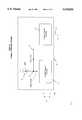
- FIG. 1is a schematic diagram of one example of an oscillator circuit in accordance with this invention.
- FIG. 2is a schematic diagram of an example of an implementation of the voltage to reactance element shown in FIG. 1.
- FIG. 1shows an example of a voltage controlled oscillator in accordance with this invention.
- the oscillatorcomprises an amplifier section 10 and a resonator section comprising a piezoelectric quartz crystal resonator element 12 in series with a varactor 14.
- the series combination of the resonator element 12 and the varactor 14is connected to the input 16 of the amplifier section 10.
- the impedance of the series combination in conjunction with the input impedance of the amplifier section 10determines the frequency of oscillation of the circuit of FIG. 1.
- the level of a user specified frequency control signaldetermines the capacitance of the varactor 14 via the amplifier 22 and thus the oscillation frequency of the circuit of FIG. 1. Examples of such voltage controlled oscillators are disclosed in U.S. Pat. Nos. 4,853,655 and 4,887,053.
- An example of a suitable varactoris shown in U.S. Pat. No. 4,973,922.
- the 1includes a reference signal on line 18 which has a predetermined magnitude representing a commanded value of varactor impedance which will increase the gain of the oscillator circuit in FIG. 1.
- the reference signalis connected to the input of a signal selection element 20, the output of which is connected to the input of an amplifier 22 by way of a line 24.
- the amplifierprovides a predetermined amount of amplification or attenuation of signals appearing on line 24.
- the output of the amplifier 22is connected to the junction 23 between the resonator element 12 and the varactor 14.
- the voltage level of the junction 23is thus determined by the voltage magnitude at the output of the amplifier 22 which in turn is determined by the level of the reference signal.
- the capacitance of the varactor 14varies as a function of the voltage magnitude at junction 23 and thus varies as a function of reference voltage level.
- Another input to the signal selection element 20is the previously mentioned frequency control signal appearing on line 26.
- a usersets the magnitude of the frequency control signal on line 26.
- the magnitude of the frequency control signaldetermines the impedance of the varactor 14 which in turn determines the oscillation frequency of the FIG. 1 circuit.
- the frequency of oscillationwas determined solely by the frequency control signal set by the user.
- the magnitude of the frequency control signal and thus the magnitude of the capacitance of the varactor 14can vary over fairly wide ranges. If the magnitude of the frequency control signal of line 26 is such that the impedance of the varactor 14 is high, the gain of the FIG. 1 oscillator circuit will be low and it will be difficult to reliably initiate oscillation in such a circuit.
- the voltage reference signal on line 18which has an appropriate magnitude so that the varactor 14 will have an impedance low enough for reliable initiation of oscillation, is substituted for the frequency control signal on line 26 during oscillator startup.
- the signal selection element 20operates to direct the voltage reference signal on line 18 to the input of amplifier 22 during oscillator startup.
- the voltage magnitude at node 23thus is a function of the magnitude of the voltage reference signal on line 18 during startup.
- the impedance of the varactor 14thus is set at a magnitude promoting reliable startup of the oscillator.
- the impedance of the varactor 14is such that it has a maximum capacitance and thus a minimum impedance.
- the signal selection element 20substitutes the frequency control signal on line 26 for the voltage reference signal on line 18 as an input to the amplifier 22 and node 23.
- the oscillator frequencywill then be controlled by the magnitude of the frequency control signal as selected by the user.
- Oscillation of the FIG. 1 circuitis detected by an oscillation detection circuit 28 connected to the oscillator output 30.
- the output of the detection circuit 28is connected to a control input 33 of the signal selection element 20.
- the output of the detection circuit 28commands the signal selection element 20 to direct the voltage reference signal to the input of the amplifier 22.
- the detection circuit 28commands the signal selection element 20 to direct the frequency control signal to the input of amplifier 22.
- the oscillation detection circuit 28may be a high pass filter having an input connected to output 30 and producing a dc output in substantially direct proportion to the frequency of electrical signal on output 30.
- the dc outputcan then be compared to a threshold level in a comparator circuit which produces an output signal directed to the output of the detection circuit 28 when the dc output is above the threshold thereby indicating the presence of oscillations on the output of the circuit of FIG. 1.
- any circuit capable of selectively producing a signal on its output related to one or the other of the frequency control signal on line 26 or the reference signal on line 18 in response to a control input on line 33is suitable for use as a signal selection element 20 in FIG. 1.
- the signal selection elementmay be an analog multiplexer.
- the frequency of oscillationis determined not only by the impedance of the varactor 14, but also by the input impedance of the oscillator amplifier section 10.
- the circuit of FIG. 1will oscillate if the sum of the real part of the input impedance of the amplifier section 10 and the real part of the resonator impedance comprising element 12 and varactor 14 is less than zero.
- the sum of the real and imaginary parts of the input impedance of amplifier section 10, the impedance of resonator element 12, and varactor 14is zero.
- the impedance of the resonator element 12produces a change in oscillation frequency since the sum of the impedances of amplifier section 10, resonator element 12, and varactor 14 must remain at zero in the steady state.
- the frequency of oscillationmay be changed by changing the input impedance of amplifier section 10.
- the gain of the circuit of FIG. 1also is determined by the magnitude of the input impedance of the amplifier section 10.
- the reliability of oscillator startupmay also be improved if the real part of the input impedance of the amplifier is lowered, for example, is made more negative, at startup time.
- the input impedance of amplifier section 10is determined by an input impedance determining element, such as the voltage to reactance element 32.
- the voltage to reactance element 32is controlled at oscillator startup so that the amplifier has an input impedance resulting in a high enough gain so that the oscillator easily goes into oscillation.
- the frequency control signalis directed on a line 34 to the input of an amplifier 36, which provides a predetermined amplification or attenuation of the signal appearing on line 34.
- the output of the amplifier 36is connected to an input line 38 of a signal selection element 40.
- the frequency control signalis connected to an input 42 of the voltage to reactance element 32 by the signal selection element 40.
- the frequency control signalthus controls the oscillation frequency of the circuit of FIG. 1 after oscillation has been initiated.
- the value of the frequency control signalmay be such that the voltage to reactance element 32 will cause a relatively high input impedance in the oscillator amplifier section 10 and, therefore, will result in a relatively low gain for the circuit of FIG.
- another voltage reference signalis directed on line 44 to another input of the signal selection element 40.
- the signal selection element 40directs this voltage reference signal on line 44 to the voltage to reactance element 32 during startup.
- the magnitude of the voltage reference signal on line 44is such that the voltage to reactance element 32 is set to result in an input impedance of the oscillator amplifier section 10 which will produce sufficient gain in the circuit of FIG. 1 for reliable initiation of oscillation.
- the frequency control signal from line 34is substituted for the voltage reference signal on line 44 once oscillation begins, as detected by the oscillation detection circuit 28 whose output controls the selection made by the signal selection element 40 by way of a control line 46.
- any circuit capable of selectively producing a signal on its output related to one or the other of the signal on line 38 or the reference signal on line 44 in response to a control input on line 46is suitable for use as a signal selection element 40 in FIG. 1.
- the signal selection elementmay be an analog multiplexer.
- the frequency control signal used during oscillation and the reference signal used at startupmay control a bias current in the amplification stage 10 to provide the required gain.
- the signal on line 42which is the same as the signal on line 42 in FIG. 1, is directed to an input of a voltage to current converter 48 which produces a current output on line 50 which is related to the magnitude of the signal on line 42, for example, a current output which is substantially proportional to the input on line 42.
- the current on line 50is either added to or subtracted from a node 52 in the amplification stage 10, as needed.
- the node 52also receives bias current from a constant current source 54.
- the actual level of bias current in the amplification stage 10thus is the bias current from source 54 modified by the current produced by the voltage to current converter 48.
- the gain of the amplification stage 10thus is controlled as a function of frequency control signal on line 34 or voltage reference signal on line 44 to provide increased gain for the circuit of FIG. 1 during startup to insure reliable initiation of oscillation.
- FIGS. 1 and 2are shown as involving the control of the varactor and the amplifier input impedance determining element 32 by the same control signal, they may also be controlled by different control signals.
- the initiation of oscillation in an oscillator circuitsuch as the one shown in FIG. 1 thus may be facilitated by techniques which increase the gain of the circuit during startup conditions.
- One or both of the impedance of a resonator circuit or the input impedance of an amplifier used in the oscillatormay be controlled to predetermine magnitudes during startup to achieve this increase in gain.
Landscapes
- Oscillators With Electromechanical Resonators (AREA)
- Inductance-Capacitance Distribution Constants And Capacitance-Resistance Oscillators (AREA)
Abstract
Description
Claims (17)
Priority Applications (5)
| Application Number | Priority Date | Filing Date | Title |
|---|---|---|---|
| US08/327,778US5534826A (en) | 1994-10-24 | 1994-10-24 | Oscillator with increased reliability start up |
| TW084101213ATW284935B (en) | 1994-10-24 | 1995-02-11 | |
| CA002159386ACA2159386C (en) | 1994-10-24 | 1995-09-28 | Oscillator with increased reliability start up |
| EP95307226AEP0709965A1 (en) | 1994-10-24 | 1995-10-11 | Oscillator with increased reliability startup |
| JP29727795AJP3194570B2 (en) | 1994-10-24 | 1995-10-23 | Oscillator with improved oscillation characteristics at start of oscillation and oscillation method |
Applications Claiming Priority (1)
| Application Number | Priority Date | Filing Date | Title |
|---|---|---|---|
| US08/327,778US5534826A (en) | 1994-10-24 | 1994-10-24 | Oscillator with increased reliability start up |
Publications (1)
| Publication Number | Publication Date |
|---|---|
| US5534826Atrue US5534826A (en) | 1996-07-09 |
Family
ID=23278030
Family Applications (1)
| Application Number | Title | Priority Date | Filing Date |
|---|---|---|---|
| US08/327,778Expired - LifetimeUS5534826A (en) | 1994-10-24 | 1994-10-24 | Oscillator with increased reliability start up |
Country Status (5)
| Country | Link |
|---|---|
| US (1) | US5534826A (en) |
| EP (1) | EP0709965A1 (en) |
| JP (1) | JP3194570B2 (en) |
| CA (1) | CA2159386C (en) |
| TW (1) | TW284935B (en) |
Cited By (20)
| Publication number | Priority date | Publication date | Assignee | Title |
|---|---|---|---|---|
| US5794080A (en)* | 1994-08-31 | 1998-08-11 | Nikon Corporation | Piezoelectric vibration angular velocity meter and camera using the same |
| US5844448A (en)* | 1997-09-12 | 1998-12-01 | Motorola, Inc. | Method and apparatus for optimizing an oscillator start up time |
| US6011445A (en)* | 1998-09-01 | 2000-01-04 | Admtek Incorporated | Method for oscillating and start up circuit for oscillator |
| US6154097A (en)* | 1998-04-17 | 2000-11-28 | Nec Corporation | PLL oscillating circuit including oscillating circuit with mutual conductance controlled |
| US6337604B1 (en)* | 1999-05-14 | 2002-01-08 | Telefonaktiebolaget Lm Ericsson (Publ) | Crystal oscillator |
| US20040046617A1 (en)* | 2002-09-11 | 2004-03-11 | Kuo Yao H. | Oscillator circuit having an expanded operating range |
| US20050206463A1 (en)* | 2004-03-16 | 2005-09-22 | Motorola, Inc. | Self-calibrating oscillator system |
| US20060017518A1 (en)* | 2004-07-21 | 2006-01-26 | Bruce Wilcox | Method and apparatus for reducing the start time of a vcxo |
| US20060105734A1 (en)* | 2004-11-16 | 2006-05-18 | Seiko Epson Corporation | Oscillation device and oscillation method |
| US20070030085A1 (en)* | 2005-03-24 | 2007-02-08 | Cypress Semiconductor Corp. | Regulated Capacitive Loading and Gain Control of a Crystal Oscillator During Startup and Steady State Operation |
| US7348861B1 (en)* | 2005-03-31 | 2008-03-25 | Ralink Technology, Inc. | Method and apparatus for a crystal oscillator to achieve fast start-up time, low power and frequency calibration |
| US20090131000A1 (en)* | 2007-11-21 | 2009-05-21 | Kuo Yao H | Radio receiver system |
| US20100013564A1 (en)* | 2007-01-31 | 2010-01-21 | Continental Automotive Gmbh | Device |
| DE19914698B4 (en)* | 1998-04-02 | 2010-12-16 | Seiko Epson Corp. | resonant circuit |
| US7902933B1 (en) | 2006-03-29 | 2011-03-08 | Cypress Semiconductor Corporation | Oscillator circuit |
| US20110241786A1 (en)* | 2010-03-30 | 2011-10-06 | Tyco Healthcare Group Lp | System and Method for Improved Start-Up of Self-Oscillating Electro-Mechanical Surgical Devices |
| US20130023208A1 (en)* | 2005-03-11 | 2013-01-24 | Innovision Research & Technology Plc | Communication devices having controlled impedances |
| US8975972B2 (en)* | 2012-07-05 | 2015-03-10 | Infineon Technologies Ag | Oscillator system |
| US9007138B2 (en) | 2013-05-31 | 2015-04-14 | Freescale Semiconductor, Inc. | Oscillator with startup circuitry |
| US9722583B2 (en) | 2015-08-20 | 2017-08-01 | SK Hynix Inc. | Periodic signal generation circuit and semiconductor system including the same |
Families Citing this family (10)
| Publication number | Priority date | Publication date | Assignee | Title |
|---|---|---|---|---|
| US6052036A (en)* | 1997-10-31 | 2000-04-18 | Telefonaktiebolaget L M Ericsson | Crystal oscillator with AGC and on-chip tuning |
| JP3932661B2 (en)* | 1998-03-31 | 2007-06-20 | 松下電器産業株式会社 | Angular velocity sensor drive circuit |
| DE102005001684A1 (en) | 2005-01-13 | 2006-07-27 | Infineon Technologies Ag | Quick-start circuit for quartz oscillators |
| KR20080069262A (en)* | 2005-11-24 | 2008-07-25 | 텔레폰악티에볼라겟엘엠에릭슨(펍) | Oscillator with start control |
| EP1791252A1 (en)* | 2005-11-24 | 2007-05-30 | Telefonaktiebolaget LM Ericsson (publ) | Oscillator comprising a startup control device |
| US7592878B2 (en)* | 2007-04-05 | 2009-09-22 | Qualcomm Incorporated | Method and apparatus for generating oscillating signals |
| US8188802B2 (en) | 2009-05-13 | 2012-05-29 | Qualcomm Incorporated | System and method for efficiently generating an oscillating signal |
| US8629730B2 (en)* | 2009-12-22 | 2014-01-14 | Asahi Kasei Microdevices Corporation | Oscillator |
| JP6128483B2 (en)* | 2013-03-09 | 2017-05-17 | セイコーNpc株式会社 | Voltage controlled oscillator |
| CN103346782B (en)* | 2013-07-09 | 2015-10-14 | 东南大学 | A kind of fast start-up crystal oscillator |
Citations (22)
| Publication number | Priority date | Publication date | Assignee | Title |
|---|---|---|---|---|
| US3619803A (en)* | 1970-03-16 | 1971-11-09 | Gte Sylvania Inc | Temperature and voltage compensation for transistorized vco control circuit |
| US4039973A (en)* | 1975-04-21 | 1977-08-02 | Hitachi, Ltd. | Initiation circuit in a crystal-controlled oscillator |
| US4282496A (en)* | 1979-08-29 | 1981-08-04 | Rca Corporation | Starting circuit for low power oscillator circuit |
| US4307354A (en)* | 1978-08-22 | 1981-12-22 | Nippon Electric Co., Ltd. | Crystal oscillator circuit having rapid starting characteristics and a low power consumption |
| US4517533A (en)* | 1983-10-26 | 1985-05-14 | Zenith Electronics Corporation | Integrated crystal VCO |
| US4518930A (en)* | 1982-07-30 | 1985-05-21 | Rockwell International Corporation | Negative resistance circuit for VCO |
| US4667170A (en)* | 1985-09-26 | 1987-05-19 | Western Digital Corporation | Voltage controlled oscillator with self-adjustment of operating point |
| US4675617A (en)* | 1986-02-03 | 1987-06-23 | Martin Kenneth W | Stable voltage controlled oscillator |
| US4704587A (en)* | 1986-12-04 | 1987-11-03 | Western Digital Corporation | Crystal oscillator circuit for fast reliable start-up |
| US4743864A (en)* | 1985-10-23 | 1988-05-10 | Hitachi, Ltd | Power saving intermittently operated phase locked loop |
| US4748425A (en)* | 1987-02-18 | 1988-05-31 | Motorola, Inc. | VCO range shift and modulation device |
| US4853655A (en)* | 1987-11-27 | 1989-08-01 | American Telephone And Telegraph Company, At&T Bell Laboratories | High frequency CMOS oscillator |
| US4887053A (en)* | 1987-11-27 | 1989-12-12 | American Telephone And Telegraph Company | High frequency VLSI oscillator |
| US4896122A (en)* | 1989-07-14 | 1990-01-23 | Motorola, Inc. | Multiple bandwidth crystal controlled oscillator |
| US4918408A (en)* | 1987-12-18 | 1990-04-17 | Kabushiki Kaisha Toshiba | Oscillation circuit |
| US4973922A (en)* | 1987-11-27 | 1990-11-27 | At&T Bell Laboratories | Voltage controlled variable capacitor and oscillator using it |
| US5041802A (en)* | 1989-10-11 | 1991-08-20 | Zilog, Inc. | Low power oscillator with high start-up ability |
| US5142251A (en)* | 1991-10-03 | 1992-08-25 | National Semiconductor Corporation | Wide band selectable gain and operating frequency CMOS oscillator circuit |
| US5175884A (en)* | 1990-06-01 | 1992-12-29 | Motorola, Inc. | Voltage controlled oscillator with current control |
| US5334954A (en)* | 1990-04-28 | 1994-08-02 | Deutsche Thomson-Brandt Gmbh | Phase locked loop circuit |
| US5359297A (en)* | 1993-10-28 | 1994-10-25 | Motorola, Inc. | VCO power-up circuit for PLL and method thereof |
| US5410572A (en)* | 1992-12-25 | 1995-04-25 | Mitsubishi Denki Kabushiki Kaisha | Phase locked loop circuit |
Family Cites Families (6)
| Publication number | Priority date | Publication date | Assignee | Title |
|---|---|---|---|---|
| CA1010121A (en)* | 1975-03-20 | 1977-05-10 | Allistair Towle | Stabilized crystal controlled oscillator |
| JPS59140703A (en)* | 1983-01-31 | 1984-08-13 | Sanyo Electric Co Ltd | Oscillating circuit |
| US4968952A (en)* | 1989-06-02 | 1990-11-06 | Motorola, Inc. | Voltage control oscillator with automatic current control |
| NL8902900A (en)* | 1989-11-23 | 1991-06-17 | Catena Microelect Bv | VOLTAGE CONTROLLED OSCILLATOR. |
| US5097228A (en)* | 1991-02-28 | 1992-03-17 | Hewlett-Packard Company | Wideband oscillator with bias compensation |
| JP2626432B2 (en)* | 1992-12-07 | 1997-07-02 | 日本電気株式会社 | Oscillation circuit |
- 1994
- 1994-10-24USUS08/327,778patent/US5534826A/ennot_activeExpired - Lifetime
- 1995
- 1995-02-11TWTW084101213Apatent/TW284935B/zhactive
- 1995-09-28CACA002159386Apatent/CA2159386C/ennot_activeExpired - Fee Related
- 1995-10-11EPEP95307226Apatent/EP0709965A1/ennot_activeWithdrawn
- 1995-10-23JPJP29727795Apatent/JP3194570B2/ennot_activeExpired - Fee Related
Patent Citations (22)
| Publication number | Priority date | Publication date | Assignee | Title |
|---|---|---|---|---|
| US3619803A (en)* | 1970-03-16 | 1971-11-09 | Gte Sylvania Inc | Temperature and voltage compensation for transistorized vco control circuit |
| US4039973A (en)* | 1975-04-21 | 1977-08-02 | Hitachi, Ltd. | Initiation circuit in a crystal-controlled oscillator |
| US4307354A (en)* | 1978-08-22 | 1981-12-22 | Nippon Electric Co., Ltd. | Crystal oscillator circuit having rapid starting characteristics and a low power consumption |
| US4282496A (en)* | 1979-08-29 | 1981-08-04 | Rca Corporation | Starting circuit for low power oscillator circuit |
| US4518930A (en)* | 1982-07-30 | 1985-05-21 | Rockwell International Corporation | Negative resistance circuit for VCO |
| US4517533A (en)* | 1983-10-26 | 1985-05-14 | Zenith Electronics Corporation | Integrated crystal VCO |
| US4667170A (en)* | 1985-09-26 | 1987-05-19 | Western Digital Corporation | Voltage controlled oscillator with self-adjustment of operating point |
| US4743864A (en)* | 1985-10-23 | 1988-05-10 | Hitachi, Ltd | Power saving intermittently operated phase locked loop |
| US4675617A (en)* | 1986-02-03 | 1987-06-23 | Martin Kenneth W | Stable voltage controlled oscillator |
| US4704587A (en)* | 1986-12-04 | 1987-11-03 | Western Digital Corporation | Crystal oscillator circuit for fast reliable start-up |
| US4748425A (en)* | 1987-02-18 | 1988-05-31 | Motorola, Inc. | VCO range shift and modulation device |
| US4853655A (en)* | 1987-11-27 | 1989-08-01 | American Telephone And Telegraph Company, At&T Bell Laboratories | High frequency CMOS oscillator |
| US4887053A (en)* | 1987-11-27 | 1989-12-12 | American Telephone And Telegraph Company | High frequency VLSI oscillator |
| US4973922A (en)* | 1987-11-27 | 1990-11-27 | At&T Bell Laboratories | Voltage controlled variable capacitor and oscillator using it |
| US4918408A (en)* | 1987-12-18 | 1990-04-17 | Kabushiki Kaisha Toshiba | Oscillation circuit |
| US4896122A (en)* | 1989-07-14 | 1990-01-23 | Motorola, Inc. | Multiple bandwidth crystal controlled oscillator |
| US5041802A (en)* | 1989-10-11 | 1991-08-20 | Zilog, Inc. | Low power oscillator with high start-up ability |
| US5334954A (en)* | 1990-04-28 | 1994-08-02 | Deutsche Thomson-Brandt Gmbh | Phase locked loop circuit |
| US5175884A (en)* | 1990-06-01 | 1992-12-29 | Motorola, Inc. | Voltage controlled oscillator with current control |
| US5142251A (en)* | 1991-10-03 | 1992-08-25 | National Semiconductor Corporation | Wide band selectable gain and operating frequency CMOS oscillator circuit |
| US5410572A (en)* | 1992-12-25 | 1995-04-25 | Mitsubishi Denki Kabushiki Kaisha | Phase locked loop circuit |
| US5359297A (en)* | 1993-10-28 | 1994-10-25 | Motorola, Inc. | VCO power-up circuit for PLL and method thereof |
Non-Patent Citations (4)
| Title |
|---|
| "A Simple Model for Quartz Resonator Low Level Drive Sensitivity" Forty-Fifth Annual Symposium on Frequency Control, L. Dworsky and R. Kinsman, Motorola, Inc. IEEE 1991, pp. 148-155. |
| "The Current Dependency of Crystal Unit Resistance at Low Drive Level" Proceedings of the 25th Annual Symposium on Frequency Control Apr. 26-28, 1971, U.S. Army Electronics Command, Fort Monmouth, New Jersey pp. 139-147. Nonaka et al. |
| A Simple Model for Quartz Resonator Low Level Drive Sensitivity Forty Fifth Annual Symposium on Frequency Control, L. Dworsky and R. Kinsman, Motorola, Inc. IEEE 1991, pp. 148 155.* |
| The Current Dependency of Crystal Unit Resistance at Low Drive Level Proceedings of the 25th Annual Symposium on Frequency Control Apr. 26 28, 1971, U.S. Army Electronics Command, Fort Monmouth, New Jersey pp. 139 147. Nonaka et al.* |
Cited By (31)
| Publication number | Priority date | Publication date | Assignee | Title |
|---|---|---|---|---|
| US5794080A (en)* | 1994-08-31 | 1998-08-11 | Nikon Corporation | Piezoelectric vibration angular velocity meter and camera using the same |
| USRE42923E1 (en)* | 1994-08-31 | 2011-11-15 | Panasonic Corporation | Piezoelectric vibration angular velocity meter and camera using the same |
| US5844448A (en)* | 1997-09-12 | 1998-12-01 | Motorola, Inc. | Method and apparatus for optimizing an oscillator start up time |
| DE19914698B4 (en)* | 1998-04-02 | 2010-12-16 | Seiko Epson Corp. | resonant circuit |
| US6154097A (en)* | 1998-04-17 | 2000-11-28 | Nec Corporation | PLL oscillating circuit including oscillating circuit with mutual conductance controlled |
| US6011445A (en)* | 1998-09-01 | 2000-01-04 | Admtek Incorporated | Method for oscillating and start up circuit for oscillator |
| US6337604B1 (en)* | 1999-05-14 | 2002-01-08 | Telefonaktiebolaget Lm Ericsson (Publ) | Crystal oscillator |
| US20040046617A1 (en)* | 2002-09-11 | 2004-03-11 | Kuo Yao H. | Oscillator circuit having an expanded operating range |
| US6924708B2 (en) | 2002-09-11 | 2005-08-02 | Visteon Global Technologies, Inc. | Oscillator circuit having an expanded operating range |
| US20050206463A1 (en)* | 2004-03-16 | 2005-09-22 | Motorola, Inc. | Self-calibrating oscillator system |
| US7126433B2 (en) | 2004-03-16 | 2006-10-24 | Freescale Semiconductor, Inc. | Self-calibrating oscillator system |
| US20060017518A1 (en)* | 2004-07-21 | 2006-01-26 | Bruce Wilcox | Method and apparatus for reducing the start time of a vcxo |
| US7009460B2 (en)* | 2004-07-21 | 2006-03-07 | Sony Ericsson Mobile Communications Ab | Method and apparatus for reducing the start time of a VCXO |
| US20060105734A1 (en)* | 2004-11-16 | 2006-05-18 | Seiko Epson Corporation | Oscillation device and oscillation method |
| US7496331B2 (en)* | 2004-11-16 | 2009-02-24 | Seiko Epson Corporation | Oscillation device and oscillation method |
| US9020425B2 (en)* | 2005-03-11 | 2015-04-28 | Broadcom Europe Limited | Communication devices having controlled impedances |
| US20130023208A1 (en)* | 2005-03-11 | 2013-01-24 | Innovision Research & Technology Plc | Communication devices having controlled impedances |
| US20070030085A1 (en)* | 2005-03-24 | 2007-02-08 | Cypress Semiconductor Corp. | Regulated Capacitive Loading and Gain Control of a Crystal Oscillator During Startup and Steady State Operation |
| US7859355B2 (en)* | 2005-03-24 | 2010-12-28 | Cypress Semiconductor Corporation | Regulated capacitive loading and gain control of a crystal oscillator during startup and steady state operation |
| US7348861B1 (en)* | 2005-03-31 | 2008-03-25 | Ralink Technology, Inc. | Method and apparatus for a crystal oscillator to achieve fast start-up time, low power and frequency calibration |
| US7902933B1 (en) | 2006-03-29 | 2011-03-08 | Cypress Semiconductor Corporation | Oscillator circuit |
| US20100013564A1 (en)* | 2007-01-31 | 2010-01-21 | Continental Automotive Gmbh | Device |
| US8143954B2 (en) | 2007-01-31 | 2012-03-27 | Continental Automotive Gmbh | Oscillation device with auxiliary oscillating means |
| US20090131000A1 (en)* | 2007-11-21 | 2009-05-21 | Kuo Yao H | Radio receiver system |
| US20110241786A1 (en)* | 2010-03-30 | 2011-10-06 | Tyco Healthcare Group Lp | System and Method for Improved Start-Up of Self-Oscillating Electro-Mechanical Surgical Devices |
| US8665031B2 (en) | 2010-03-30 | 2014-03-04 | Covidien Lp | System and method for improved start-up of self-oscillating electro-mechanical surgical devices |
| US8258886B2 (en)* | 2010-03-30 | 2012-09-04 | Tyco Healthcare Group Lp | System and method for improved start-up of self-oscillating electro-mechanical surgical devices |
| US8975972B2 (en)* | 2012-07-05 | 2015-03-10 | Infineon Technologies Ag | Oscillator system |
| US9007138B2 (en) | 2013-05-31 | 2015-04-14 | Freescale Semiconductor, Inc. | Oscillator with startup circuitry |
| US9722583B2 (en) | 2015-08-20 | 2017-08-01 | SK Hynix Inc. | Periodic signal generation circuit and semiconductor system including the same |
| US9887691B2 (en) | 2015-08-20 | 2018-02-06 | SK Hynix Inc. | Periodic signal generation circuit and semiconductor system including the same |
Also Published As
| Publication number | Publication date |
|---|---|
| EP0709965A1 (en) | 1996-05-01 |
| CA2159386A1 (en) | 1996-04-25 |
| JP3194570B2 (en) | 2001-07-30 |
| TW284935B (en) | 1996-09-01 |
| JPH08213836A (en) | 1996-08-20 |
| CA2159386C (en) | 2000-01-25 |
Similar Documents
| Publication | Publication Date | Title |
|---|---|---|
| US5534826A (en) | Oscillator with increased reliability start up | |
| US5216338A (en) | Circuit arrangement for accurately and effectively driving an ultrasonic transducer | |
| EP0947803B1 (en) | Angular velocity sensor driving circuit | |
| WO2004021558A3 (en) | Method of modulation gain calibration and system thereof | |
| US5504457A (en) | Pulsed power amplifier for amplifying RF signals | |
| JP2001358534A (en) | Amplitude control oscillator and conversion circuit | |
| US6057742A (en) | Low power oscillator having fast start-up times | |
| JPH04200282A (en) | Drive device for ultrasonic motor | |
| JP4075152B2 (en) | Angular velocity sensor | |
| US4209758A (en) | Method and apparatus for the automatic matching of a transmitter to an antenna | |
| US5834983A (en) | Wideband oscillator with automatic bias control | |
| US4914403A (en) | Cesium oscillator | |
| US5459438A (en) | Negative feedback frequency stabilized pulse oscillator | |
| US4456891A (en) | Radio frequency source circuit primarily for igniting the lamp of a rubidium frequency standard | |
| US5477197A (en) | Voltage controlled oscillator with improved voltage versus frequency characteristic | |
| US4535280A (en) | Stabilizing circuit for an inverse rectifier motor control | |
| US4639689A (en) | Inductive loop detector | |
| JPH07303635A (en) | Drive device for ultrasonic oscillator | |
| JPH08178302A (en) | Method for controlling lead time of humidity sensor in microwave oven | |
| JPS5936030Y2 (en) | sweep receiver | |
| US5332980A (en) | Modulation circuit having frequency sensitive power supply voltage | |
| JPS59205802A (en) | Oscillating circuit with start trigger | |
| JPS5586209A (en) | Automatic high-frequency level regulator circuit | |
| JPH05161348A (en) | Switching regulator | |
| SU1499308A1 (en) | Apparatus for adjusting toner concentration in developing mixture |
Legal Events
| Date | Code | Title | Description |
|---|---|---|---|
| AS | Assignment | Owner name:AT&T CORP., NEW YORK Free format text:ASSIGNMENT OF ASSIGNORS INTEREST;ASSIGNOR:LOGAN, SHAWN MICHAEL;REEL/FRAME:007282/0001 Effective date:19941012 | |
| AS | Assignment | Owner name:AT&T IPM CORP., FLORIDA Free format text:ASSIGNMENT OF ASSIGNORS INTEREST;ASSIGNOR:AT&T CORP.;REEL/FRAME:007467/0511 Effective date:19950428 | |
| STCF | Information on status: patent grant | Free format text:PATENTED CASE | |
| FEPP | Fee payment procedure | Free format text:PAYOR NUMBER ASSIGNED (ORIGINAL EVENT CODE: ASPN); ENTITY STATUS OF PATENT OWNER: LARGE ENTITY | |
| FPAY | Fee payment | Year of fee payment:4 | |
| FPAY | Fee payment | Year of fee payment:8 | |
| FPAY | Fee payment | Year of fee payment:12 | |
| AS | Assignment | Owner name:DEUTSCHE BANK AG NEW YORK BRANCH, AS COLLATERAL AG Free format text:PATENT SECURITY AGREEMENT;ASSIGNORS:LSI CORPORATION;AGERE SYSTEMS LLC;REEL/FRAME:032856/0031 Effective date:20140506 | |
| AS | Assignment | Owner name:AVAGO TECHNOLOGIES GENERAL IP (SINGAPORE) PTE. LTD Free format text:ASSIGNMENT OF ASSIGNORS INTEREST;ASSIGNOR:AGERE SYSTEMS LLC;REEL/FRAME:035365/0634 Effective date:20140804 | |
| AS | Assignment | Owner name:AGERE SYSTEMS LLC, PENNSYLVANIA Free format text:TERMINATION AND RELEASE OF SECURITY INTEREST IN PATENT RIGHTS (RELEASES RF 032856-0031);ASSIGNOR:DEUTSCHE BANK AG NEW YORK BRANCH, AS COLLATERAL AGENT;REEL/FRAME:037684/0039 Effective date:20160201 Owner name:LSI CORPORATION, CALIFORNIA Free format text:TERMINATION AND RELEASE OF SECURITY INTEREST IN PATENT RIGHTS (RELEASES RF 032856-0031);ASSIGNOR:DEUTSCHE BANK AG NEW YORK BRANCH, AS COLLATERAL AGENT;REEL/FRAME:037684/0039 Effective date:20160201 |