US5534741A - Ultrasonic pulse cleaner - Google Patents
Ultrasonic pulse cleanerDownload PDFInfo
- Publication number
- US5534741A US5534741AUS08/311,874US31187494AUS5534741AUS 5534741 AUS5534741 AUS 5534741AUS 31187494 AUS31187494 AUS 31187494AUS 5534741 AUS5534741 AUS 5534741A
- Authority
- US
- United States
- Prior art keywords
- ultrasonic energy
- generating element
- ultrasonic
- energy generating
- pulse cleaner
- Prior art date
- Legal status (The legal status is an assumption and is not a legal conclusion. Google has not performed a legal analysis and makes no representation as to the accuracy of the status listed.)
- Expired - Lifetime
Links
- 238000004140cleaningMethods0.000description8
- 230000010355oscillationEffects0.000description8
- 239000003990capacitorSubstances0.000description5
- 238000010586diagramMethods0.000description5
- 238000003860storageMethods0.000description3
- 239000007788liquidSubstances0.000description2
- 229920002799BoPETPolymers0.000description1
- 101100321817Human parvovirus B19 (strain HV) 7.5K geneProteins0.000description1
- 239000005041Mylar™Substances0.000description1
- 239000012459cleaning agentSubstances0.000description1
- 230000007812deficiencyEffects0.000description1
- 230000001419dependent effectEffects0.000description1
- 230000000881depressing effectEffects0.000description1
- 230000001939inductive effectEffects0.000description1
- 238000004519manufacturing processMethods0.000description1
- 239000000463materialSubstances0.000description1
- 239000002184metalSubstances0.000description1
- 230000004048modificationEffects0.000description1
- 238000012986modificationMethods0.000description1
- 230000001052transient effectEffects0.000description1
- 238000004506ultrasonic cleaningMethods0.000description1
Images


Classifications
- B—PERFORMING OPERATIONS; TRANSPORTING
- B06—GENERATING OR TRANSMITTING MECHANICAL VIBRATIONS IN GENERAL
- B06B—METHODS OR APPARATUS FOR GENERATING OR TRANSMITTING MECHANICAL VIBRATIONS OF INFRASONIC, SONIC, OR ULTRASONIC FREQUENCY, e.g. FOR PERFORMING MECHANICAL WORK IN GENERAL
- B06B1/00—Methods or apparatus for generating mechanical vibrations of infrasonic, sonic, or ultrasonic frequency
- B06B1/02—Methods or apparatus for generating mechanical vibrations of infrasonic, sonic, or ultrasonic frequency making use of electrical energy
- B06B1/0207—Driving circuits
- B06B1/0215—Driving circuits for generating pulses, e.g. bursts of oscillations, envelopes
- B—PERFORMING OPERATIONS; TRANSPORTING
- B06—GENERATING OR TRANSMITTING MECHANICAL VIBRATIONS IN GENERAL
- B06B—METHODS OR APPARATUS FOR GENERATING OR TRANSMITTING MECHANICAL VIBRATIONS OF INFRASONIC, SONIC, OR ULTRASONIC FREQUENCY, e.g. FOR PERFORMING MECHANICAL WORK IN GENERAL
- B06B2201/00—Indexing scheme associated with B06B1/0207 for details covered by B06B1/0207 but not provided for in any of its subgroups
- B06B2201/50—Application to a particular transducer type
- B06B2201/55—Piezoelectric transducer
- B—PERFORMING OPERATIONS; TRANSPORTING
- B06—GENERATING OR TRANSMITTING MECHANICAL VIBRATIONS IN GENERAL
- B06B—METHODS OR APPARATUS FOR GENERATING OR TRANSMITTING MECHANICAL VIBRATIONS OF INFRASONIC, SONIC, OR ULTRASONIC FREQUENCY, e.g. FOR PERFORMING MECHANICAL WORK IN GENERAL
- B06B2201/00—Indexing scheme associated with B06B1/0207 for details covered by B06B1/0207 but not provided for in any of its subgroups
- B06B2201/70—Specific application
- B06B2201/71—Cleaning in a tank
Definitions
- the present inventionrelates generally to ultrasonic cleaners and, more particularly, to an ultrasonic cleaner employing pulsing of the ultrasonic cleaning element.
- Ultrasonic cleanerswhich employ ultrasonic energy generating elements for producing ultrasonic energy that cleans a workpiece.
- the known ultrasonic cleanershave the disadvantage of having a high duty cycle. That is, the ultrasonic energy generating element, generally a Piezo device, is energized for a large percentage of the time that the cleaner is in operation. This high duty cycle results in the production of a great amount of heat, wasting energy and forcing the use of thicker and more expensive materials to dissipate this heat.
- the constant bombardment of the workpiece with ultrasonic energydoes not provide optimum cleaning of the workpiece.
- FIGS. 6(A) and 6(B)are circuit diagrams of that conventional cleaner.
- FIG. 1is a perspective view of an ultrasonic pulse cleaner according to the present invention
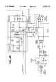
- FIG. 2is a circuit diagram of an ultrasonic pulse cleaner according to the present invention.
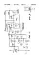
- FIG. 3is a detailed circuit diagram of the timer circuit of FIG. 2;
- FIG. 4(A)is a graph showing a waveform present at pin 5 of U1 of FIG. 3;
- FIG. 4(B)is a graph showing a waveform present at pin 10 of U1 of FIG. 3;
- FIG. 4(C)is a graph showing a waveform present at node D of the timer shown in FIG. 3;
- FIG. 5shows Q1, a 2N6071A triac
- FIG. 6(A)is detailed circuit diagram of a timer section of a conventional ultrasonic cleaner.
- FIG. 6(B)is detailed circuit diagram of a power section of a conventional ultrasonic cleaner.
- an ultrasonic pulse cleaner 1according to the present invention is shown.
- the ultrasonic pulse cleaner 1has three position switch SW1, LED1, LED2, and reset button B1.
- the graduated storage cup 3, which includes lid 3a and jewelry basket 3bis sized to fit within well 5.
- the ultrasonic pulse cleaner 1is used by placing a liquid cleaning solution and the workpiece (not shown) in the storage cup 3, placing the storage cup 3 within the well 5 and setting the switch SW1 to either the NORMAL or HIGH position. In the alternative, the cleaning solution and the workpiece may be placed directly into well 5.
- FIG. 2a circuit 10 for an ultrasonic pulse cleaner according to the present invention is shown.
- Power switch SW1provides power to only diode D30 in the NORMAL position so that the +power coming from diode D10 at node A is 1/2 wave rectified, 60 Hz, pulsating DC.
- switch SW1is switched to the HIGH position, diode D40 is also connected and the + power coming from diode D10 at node A is full wave rectified to 120 Hz, pulsating DC.
- the Piezo drive circuit 30self oscillates, pulling inductor L10 up to + power and down to common at or about the resonating frequency of the Piezo element 50 (40 KHz). This oscillation causes the Piezo element end of inductor L10 to reach, about 1000 V to drive the Piezo element 50 in its Axial mode which, when connected to a metal well (shown in FIG. 1 as element 5), vibrates the well and its contents.
- the contentspreferably includes a liquid cleaning solution for facilitating the cleansing of the workpiece.
- Piezo drive circuit 30The self oscillation of Piezo drive circuit 30 is as follows. When transistor Q10 is turned on, inductor L10 charges positively, and transistor Q20 is turned off. When inductor L10's inductive charge begins to collapse, it feeds back through transformer T10 to switch transistor Q10 off and transistor Q20 on, pulling down on inductor L10.
- the oscillation frequencyis dependent mainly upon the characteristics of the Piezo element 50.
- the 40 KHz oscillationis modulated on and off by either the 60 Hz 1/2 sine wave in the NORMAL mode or by the 120 Hz 1/2 sine wave in the HIGH mode.
- Inductor L20 and capacitor C10form a line filter to keep the 40 KHz from radiating into the power line.
- R10 and R30set the bias and R20, R40, C30, and C40 set the drive current of Q10 and Q20.
- D50 and D60protect Q10 and Q20 from reverse transients.
- the timer circuit 70which is connected at nodes B, C, and D, is shown in detail in FIG. 3. As seen in FIG. 3, nodes B, C, and D correspond to nodes B, C, and D of FIG. 2.
- Resistor R1is connected to one side of the line-in at node B. Resistor R1 supplies timer current through diode D4 and the LED1 into the 7.5 V Zenner diode Z1 to create a low voltage DC supply. Capacitor C1 is the DC power supply filter capacitor.
- Capacitor C2resets pin 12 of U1, a 4060 timer, during initial power on. Resistor R2 charges C2, pulling pin 12 to ground and permitting the timer to run. C3, R3, and R4 make up the oscillator that drives the counter side of U1. D1 is pulled on and shuts off the oscillator at the end of approximately 5 minutes of running, leaving all other outputs of the 4060 timer down.
- Diode D3connects the pulsing output of pin 10 of the 4060 timer to the base of transistor Q2, while diode D2, which is connected to pin 5 of the 4060 timer, gates the pulsing on and off about every 2.5 seconds At the end of 5 minutes of running, pins 5 and 10 of the 4060 timer go low, disconnecting both D2 and D3.
- triac Q1is a sensitive gate triac that requires 5 ma or more gate current in quadrant 2 and 3 (negative gate current in relation to MT1).
- the gate of the triac Q1is driven with about 5 ma, which leaves almost no current for the Zenner diode Z1 and the + supply ranges from 7.5 V when the timer is off to about 6 V with the timer running.
- the signals from D2 and D3turn transistor Q2 on and off.
- Q2When Q2 is turned on, its collector comes down, pulling the cathode of LED2 down below triac Q1's MT1 terminal, causing about 5 ma of gate current to flow into triac Q1, turning it and the Piezo element 50 on.
- pin 5 of U1controls the 2.5 second gating of the triac Q1 between the pulsed and non-pulsed modes through D2 and pin 10 provides the pulsing of the triac through D3. That is, when pin 5 of U1 goes high, nodes B and D receive continuous 115 V input power regardless of the state of pin 10 of U1. However, when pin 5 of U1 goes low, nodes B and D receive 115 V input power only when pin 10 of U1 goes high, that is, about 10 times every second.
- the 10 Hz pulsing provided through D3 by pin 10 of U1is gated by pin 5 of U1 through D2 to provide pulsing every other 2.5 seconds, with continuous operation (pin 5 of U1 being high) occurring between the pulsing mode (pin 5 of U1 being low).
- capacitor C1discharges through resistor R6. This takes about 10 seconds before power on will restart the counter. In the alternative, pushing the reset button B1 restarts the counter.
- the switch SW1when the switch SW1 is moved to either the NORMAL or HIGH position the red LED1 comes on.
- the oscillation of the Piezo element 50is then modulated on and off by timer circuit 70 at a frequency of about 10 Hz for about 2.5 seconds Following that interval the Piezo element 50 oscillates without the additional modulation for about 2.5more seconds and then the cycle repeats, that is, 2.5 seconds of modulated oscillation and 2.5 seconds of oscillation without the 10 Hz modulation. After running for approximately 5 minutes, the cleaner shuts off.
- the green LED2tracks the pulsing on and off, that is, the 10 Hz modulation. This LED2 goes off at the end of the 5 minute run time of the cleaner while the red LED1 remains illuminated until the switch SW1 is turned OFF.
- the ultrasonic oscillation of the piezo element 50 at approximately 40 KHzis at a frequency too high to produce visible waves in the cleaning solution.
- the 60 Hz and 120 Hz modulation of the piezo element 50 in the NORMAL and HIGH modes, respectivelyproduces small visible waves in the cleaning solution.
- the 10 Hz modulation of the piezo element 50produces even larger visible waves in the cleaning solution, which aid in cleaning the workpiece.
- the power to the cleanermust be shut off for about 10 seconds before it can be turned back on in order to allow the timer to reset.
- the usercan restart the timer by depressing the reset button B1.
Landscapes
- Engineering & Computer Science (AREA)
- Mechanical Engineering (AREA)
- Apparatuses For Generation Of Mechanical Vibrations (AREA)
Abstract
Description
TABLE 1 ______________________________________ R1 7.5K 1W 5% R2, 4100K 1/4W 51/4 % R3 750KW 5% R5 750 ohm 1/4W 51/4 % R6 20KW 51/4 % R7 10KW 5% R8, 9100K 1/4W 5% Z1 7.5V Zenner 1/4 W LED1 Red super bright (runs on less than 10 ma) LED2 Green super bright (runs on 5 ma) C1 100 Ufd 10 VElectrolytic C2 1 Ufd 10 V Electrolytic C3 .1 Ufd Mylar D1, 2, 3 diodes 1N4148 (or any small signal diode) U1 4060 Oscillator/Timer Q1 2N6071A Triac, 200 V, 5 ma gate (II & III) Q2 2N3904 NPN transistor ______________________________________
Claims (9)
Priority Applications (1)
| Application Number | Priority Date | Filing Date | Title |
|---|---|---|---|
| US08/311,874US5534741A (en) | 1994-09-26 | 1994-09-26 | Ultrasonic pulse cleaner |
Applications Claiming Priority (1)
| Application Number | Priority Date | Filing Date | Title |
|---|---|---|---|
| US08/311,874US5534741A (en) | 1994-09-26 | 1994-09-26 | Ultrasonic pulse cleaner |
Publications (1)
| Publication Number | Publication Date |
|---|---|
| US5534741Atrue US5534741A (en) | 1996-07-09 |
Family
ID=23208894
Family Applications (1)
| Application Number | Title | Priority Date | Filing Date |
|---|---|---|---|
| US08/311,874Expired - LifetimeUS5534741A (en) | 1994-09-26 | 1994-09-26 | Ultrasonic pulse cleaner |
Country Status (1)
| Country | Link |
|---|---|
| US (1) | US5534741A (en) |
Cited By (16)
| Publication number | Priority date | Publication date | Assignee | Title |
|---|---|---|---|---|
| US5895997A (en)* | 1997-04-22 | 1999-04-20 | Ultrasonic Power Corporation | Frequency modulated ultrasonic generator |
| US20040118427A1 (en)* | 2002-12-19 | 2004-06-24 | Valerie Palfy | At-home integrated cleaning and disinfection system and method for dental hardware |
| US20040215127A1 (en)* | 1997-01-22 | 2004-10-28 | Kadziauskas Kenneth E. | Micro-burst ultrasonic power delivery |
| US6821355B1 (en) | 2003-07-29 | 2004-11-23 | Sharper Image Corporation | Automatic eyewear cleaner |
| US20050268950A1 (en)* | 2004-06-04 | 2005-12-08 | Glucksman Dov Z | Sonic jewelry cleaner |
| US20060200068A1 (en)* | 2002-10-21 | 2006-09-07 | Advanced Medical Optics, Inc. | Novel enhanced microburst ultrasonic power delivery system and method |
| US20070073309A1 (en)* | 1997-01-22 | 2007-03-29 | Advanced Medical Optics, Inc. | Control of pulse duty cycle based upon footswitch displacement |
| US7257319B1 (en) | 2004-01-15 | 2007-08-14 | Clarke Michael E | Jewelry cleaning device |
| US20080033342A1 (en)* | 2006-08-01 | 2008-02-07 | Advanced Medical Optics, Inc. | Vacuum sense control for phaco pulse shaping |
| US20080108938A1 (en)* | 2002-10-21 | 2008-05-08 | Advanced Medical Optics, Inc. | Modulated Pulsed ultrasonic power delivery system and method |
| US20100264234A1 (en)* | 2009-04-20 | 2010-10-21 | Zobele Holding S.P.A. | Liquid atomiser with piezoelectric vibration device having an improved electronic control circuit, and activation method thereof |
| US7842005B2 (en) | 2002-10-21 | 2010-11-30 | Abbott Medical Optics, Inc. | System and method for pulsed ultrasonic power delivery employing cavitational effects |
| USD643163S1 (en) | 2010-07-02 | 2011-08-09 | Sy Kessler Sales, Inc. | Jewelry cleaner |
| US9050627B2 (en) | 2011-09-02 | 2015-06-09 | Abbott Medical Optics Inc. | Systems and methods for ultrasonic power measurement and control of phacoemulsification systems |
| USD771881S1 (en) | 2015-07-27 | 2016-11-15 | Sy Kessler Sales, Inc. | Jewelry cleaner |
| US11877953B2 (en) | 2019-12-26 | 2024-01-23 | Johnson & Johnson Surgical Vision, Inc. | Phacoemulsification apparatus |
Citations (11)
| Publication number | Priority date | Publication date | Assignee | Title |
|---|---|---|---|---|
| US2985003A (en)* | 1957-01-11 | 1961-05-23 | Gen Motors Corp | Sonic washer |
| US3371233A (en)* | 1965-06-28 | 1968-02-27 | Edward G. Cook | Multifrequency ultrasonic cleaning equipment |
| US3638087A (en)* | 1970-08-17 | 1972-01-25 | Bendix Corp | Gated power supply for sonic cleaners |
| US3980906A (en)* | 1972-12-26 | 1976-09-14 | Xygiene, Inc. | Ultrasonic motor-converter systems |
| US4319155A (en)* | 1979-01-09 | 1982-03-09 | Omron Tateisi Electronics Co. | Nebulization control system for a piezoelectric ultrasonic nebulizer |
| US4376255A (en)* | 1980-03-14 | 1983-03-08 | Siemens Aktiengesellschaft | Method for pulse triggering of a piezo-electric sound-transmitting transducer |
| US4641053A (en)* | 1984-08-14 | 1987-02-03 | Matsushita Seiko Co., Ltd. | Ultrasonic liquid atomizer with an improved soft start circuit |
| US4736130A (en)* | 1987-01-09 | 1988-04-05 | Puskas William L | Multiparameter generator for ultrasonic transducers |
| US4864547A (en)* | 1986-05-20 | 1989-09-05 | Crestek, Inc. | Regulated ultrasonic generator |
| US5109174A (en)* | 1989-11-22 | 1992-04-28 | Mdt Corporation | Ultrasonic cleaner |
| US5218980A (en)* | 1991-10-10 | 1993-06-15 | Evans David H | Ultrasonic dishwasher system |
- 1994
- 1994-09-26USUS08/311,874patent/US5534741A/ennot_activeExpired - Lifetime
Patent Citations (11)
| Publication number | Priority date | Publication date | Assignee | Title |
|---|---|---|---|---|
| US2985003A (en)* | 1957-01-11 | 1961-05-23 | Gen Motors Corp | Sonic washer |
| US3371233A (en)* | 1965-06-28 | 1968-02-27 | Edward G. Cook | Multifrequency ultrasonic cleaning equipment |
| US3638087A (en)* | 1970-08-17 | 1972-01-25 | Bendix Corp | Gated power supply for sonic cleaners |
| US3980906A (en)* | 1972-12-26 | 1976-09-14 | Xygiene, Inc. | Ultrasonic motor-converter systems |
| US4319155A (en)* | 1979-01-09 | 1982-03-09 | Omron Tateisi Electronics Co. | Nebulization control system for a piezoelectric ultrasonic nebulizer |
| US4376255A (en)* | 1980-03-14 | 1983-03-08 | Siemens Aktiengesellschaft | Method for pulse triggering of a piezo-electric sound-transmitting transducer |
| US4641053A (en)* | 1984-08-14 | 1987-02-03 | Matsushita Seiko Co., Ltd. | Ultrasonic liquid atomizer with an improved soft start circuit |
| US4864547A (en)* | 1986-05-20 | 1989-09-05 | Crestek, Inc. | Regulated ultrasonic generator |
| US4736130A (en)* | 1987-01-09 | 1988-04-05 | Puskas William L | Multiparameter generator for ultrasonic transducers |
| US5109174A (en)* | 1989-11-22 | 1992-04-28 | Mdt Corporation | Ultrasonic cleaner |
| US5218980A (en)* | 1991-10-10 | 1993-06-15 | Evans David H | Ultrasonic dishwasher system |
Non-Patent Citations (2)
| Title |
|---|
| Brookstone Hard To Find Tools Catalog, Ultrasonic cleaner , p. 54, (1993).* |
| Brookstone Hard-To-Find Tools Catalog, "Ultrasonic cleaner", p. 54, (1993). |
Cited By (50)
| Publication number | Priority date | Publication date | Assignee | Title |
|---|---|---|---|---|
| US7485106B2 (en) | 1997-01-22 | 2009-02-03 | Advanced Medical Optics, Inc. | Micro-burst ultrasonic power delivery |
| US9788998B2 (en) | 1997-01-22 | 2017-10-17 | Abbott Medical Optics Inc. | Control of pulse duty cycle based upon footswitch displacement |
| US20040215127A1 (en)* | 1997-01-22 | 2004-10-28 | Kadziauskas Kenneth E. | Micro-burst ultrasonic power delivery |
| US8876747B2 (en) | 1997-01-22 | 2014-11-04 | Abbott Medical Optics Inc. | Micro-burst ultrasonic power delivery |
| US8197436B2 (en) | 1997-01-22 | 2012-06-12 | Abbott Medical Optics Inc. | Micro-burst ultrasonic power delivery |
| US8195286B2 (en) | 1997-01-22 | 2012-06-05 | Abbott Medical Optics Inc. | Control of pulse duty cycle based upon footswitch displacement |
| US20110160646A1 (en)* | 1997-01-22 | 2011-06-30 | Abbott Medical Optics Inc. | Micro-burst ultrasonic power delivery |
| US20070073309A1 (en)* | 1997-01-22 | 2007-03-29 | Advanced Medical Optics, Inc. | Control of pulse duty cycle based upon footswitch displacement |
| US20070118071A1 (en)* | 1997-01-22 | 2007-05-24 | Advanced Medical Optics, Inc. | Micro-burst ultrasonic power delivery |
| US7857783B2 (en) | 1997-01-22 | 2010-12-28 | Abbott Medical Optics Inc. | Micro-burst ultrasonic power delivery |
| US5895997A (en)* | 1997-04-22 | 1999-04-20 | Ultrasonic Power Corporation | Frequency modulated ultrasonic generator |
| US20110077583A1 (en)* | 2002-10-21 | 2011-03-31 | Abbott Medical Optics Inc. | System and method for pulsed ultrasonic power delivery employing cavitational effects |
| US8887735B2 (en) | 2002-10-21 | 2014-11-18 | Abbott Medical Optics Inc. | Modulated pulsed ultrasonic power delivery system and method |
| US20080108938A1 (en)* | 2002-10-21 | 2008-05-08 | Advanced Medical Optics, Inc. | Modulated Pulsed ultrasonic power delivery system and method |
| US10765557B2 (en) | 2002-10-21 | 2020-09-08 | Johnson & Johnson Surgical Vision, Inc. | Modulated pulsed ultrasonic power delivery system and method |
| US10245179B2 (en) | 2002-10-21 | 2019-04-02 | Johnson & Johnson Surgical Vision, Inc. | System and method for pulsed ultrasonic power delivery employing cavitation effects |
| US9707127B2 (en) | 2002-10-21 | 2017-07-18 | Abbott Medical Optics Inc. | Modulated pulsed ultrasonic power delivery system and method |
| US9642745B2 (en) | 2002-10-21 | 2017-05-09 | Abbott Medical Optics Inc. | Modulated pulsed ultrasonic power delivery system and method |
| US8945162B2 (en) | 2002-10-21 | 2015-02-03 | Abbott Medical Optics Inc. | System and method for pulsed ultrasonic power delivery employing cavitational effects |
| US8852138B2 (en) | 2002-10-21 | 2014-10-07 | Abbott Medical Optics Inc. | Modulated pulsed ultrasound power delivery system and method |
| US8231564B2 (en) | 2002-10-21 | 2012-07-31 | Abbott Medical Optics Inc. | Modulated pulsed ultrasonic power delivery system and method |
| US7842005B2 (en) | 2002-10-21 | 2010-11-30 | Abbott Medical Optics, Inc. | System and method for pulsed ultrasonic power delivery employing cavitational effects |
| US8020565B2 (en) | 2002-10-21 | 2011-09-20 | Abbott Medical Optics, Inc. | Modulated pulsed ultrasonic power delivery system and method |
| US20060200068A1 (en)* | 2002-10-21 | 2006-09-07 | Advanced Medical Optics, Inc. | Novel enhanced microburst ultrasonic power delivery system and method |
| US7938120B2 (en) | 2002-10-21 | 2011-05-10 | Abbott Medical Optics, Inc. | Enhanced microburst ultrasonic power delivery system and method |
| US20100269861A1 (en)* | 2002-12-19 | 2010-10-28 | Valerie Palfy | At-home integrated cleaning and disinfection system and method for dental hardware |
| US20040118427A1 (en)* | 2002-12-19 | 2004-06-24 | Valerie Palfy | At-home integrated cleaning and disinfection system and method for dental hardware |
| US7798159B2 (en) | 2002-12-19 | 2010-09-21 | Valerie Palfy | At-home integrated cleaning and disinfection system and method for dental hardware |
| US8002897B2 (en) | 2002-12-19 | 2011-08-23 | Integrity Engineering, Inc | At-home integrated cleaning and disinfection system and method for dental hardware |
| US20100269852A1 (en)* | 2002-12-19 | 2010-10-28 | Valerie Palfy | At-home integrated cleaning and disinfection system and method for dental hardware |
| US6821355B1 (en) | 2003-07-29 | 2004-11-23 | Sharper Image Corporation | Automatic eyewear cleaner |
| US20050061359A1 (en)* | 2003-07-29 | 2005-03-24 | Sharper Image Corporation | Automatic eyewear cleaner |
| US7257319B1 (en) | 2004-01-15 | 2007-08-14 | Clarke Michael E | Jewelry cleaning device |
| US20050268950A1 (en)* | 2004-06-04 | 2005-12-08 | Glucksman Dov Z | Sonic jewelry cleaner |
| US7448398B2 (en)* | 2004-06-04 | 2008-11-11 | Connoisseurs Products Corporation | Sonic jewelry cleaner |
| US9226849B2 (en) | 2006-08-01 | 2016-01-05 | Abbott Medical Optics Inc. | Vacuum sense control for phaco pulse shaping |
| US7785336B2 (en) | 2006-08-01 | 2010-08-31 | Abbott Medical Optics Inc. | Vacuum sense control for phaco pulse shaping |
| US8034067B2 (en) | 2006-08-01 | 2011-10-11 | Abbott Medical Optics Inc. | Vacuum sense control for phaco pulse shaping |
| US20080033342A1 (en)* | 2006-08-01 | 2008-02-07 | Advanced Medical Optics, Inc. | Vacuum sense control for phaco pulse shaping |
| US8366728B2 (en) | 2006-08-01 | 2013-02-05 | Abbott Medical Optics Inc. | Vacuum sense control for phaco pulse shaping |
| US20100114010A1 (en)* | 2006-08-01 | 2010-05-06 | Abbott Medical Optics Inc. | Vacuum sense control for phaco pulse shaping |
| US20100114009A1 (en)* | 2006-08-01 | 2010-05-06 | Abbott Medical Optics Inc. | Vacuum sense control for phaco pulse shaping |
| US8202287B2 (en) | 2006-08-01 | 2012-06-19 | Abbott Medical Optics Inc. | Vacuum sense control for phaco pulse shaping |
| US7998156B2 (en) | 2006-08-01 | 2011-08-16 | Abbott Medical Optics Inc. | Vacuum sense control for phaco pulse shaping |
| US8740107B2 (en)* | 2009-04-20 | 2014-06-03 | Zobele Holding S.P.A. | Liquid atomiser with piezoelectric vibration device having an improved electronic control circuit, and activation method thereof |
| US20100264234A1 (en)* | 2009-04-20 | 2010-10-21 | Zobele Holding S.P.A. | Liquid atomiser with piezoelectric vibration device having an improved electronic control circuit, and activation method thereof |
| USD643163S1 (en) | 2010-07-02 | 2011-08-09 | Sy Kessler Sales, Inc. | Jewelry cleaner |
| US9050627B2 (en) | 2011-09-02 | 2015-06-09 | Abbott Medical Optics Inc. | Systems and methods for ultrasonic power measurement and control of phacoemulsification systems |
| USD771881S1 (en) | 2015-07-27 | 2016-11-15 | Sy Kessler Sales, Inc. | Jewelry cleaner |
| US11877953B2 (en) | 2019-12-26 | 2024-01-23 | Johnson & Johnson Surgical Vision, Inc. | Phacoemulsification apparatus |
Similar Documents
| Publication | Publication Date | Title |
|---|---|---|
| US5534741A (en) | Ultrasonic pulse cleaner | |
| JPH0735354Y2 (en) | High frequency heating device with output control function | |
| US6842350B2 (en) | Dc-to-dc converter with flyback period detector circuit | |
| US5736884A (en) | Device for generating a control signal dependent on a variable resistance value and apparatus comprising such device | |
| JPH07101987B2 (en) | Power supply | |
| EP1006647A3 (en) | Switching power supply unit | |
| US4358654A (en) | Static power switching system for induction heating | |
| EP0291742B1 (en) | Power supply device with a blocking oscillator | |
| US3448335A (en) | High frequency ac-dc fluorescent lamp driver circuit | |
| JPS59139858A (en) | Power source | |
| US5313145A (en) | Power supply for a gas discharge device | |
| KR200175715Y1 (en) | Induction heating apparatus | |
| JPH02257744A (en) | Telephone ringing signal generator | |
| JPH01298956A (en) | switching power supply | |
| US4975555A (en) | Microwave oven with timer device | |
| JPS6142305Y2 (en) | ||
| JPS6110818A (en) | Drive circuit of electrostrictive actuator | |
| JPH0337798U (en) | ||
| JPS5939869B2 (en) | induction heating device | |
| JPH0394087U (en) | ||
| JPS6116616Y2 (en) | ||
| KR100213492B1 (en) | Controlling device of vacuum cleaner motor | |
| KR880002301Y1 (en) | Refrigeration control circuit of refrigerator | |
| JPS6211913B2 (en) | ||
| JPH0243114Y2 (en) |
Legal Events
| Date | Code | Title | Description |
|---|---|---|---|
| AS | Assignment | Owner name:SHARPER IMAGE CORPORATION, CALIFORNIA Free format text:ASSIGNMENT OF ASSIGNORS INTEREST;ASSIGNOR:SMITH, BLAINE M.;REEL/FRAME:007264/0734 Effective date:19941121 Owner name:SHARPER IMAGE CORPORATION, CALIFORNIA Free format text:ASSIGNMENT OF ASSIGNORS INTEREST;ASSIGNOR:SMITH, BLAINE M.;REEL/FRAME:007228/0661 Effective date:19941121 | |
| STCF | Information on status: patent grant | Free format text:PATENTED CASE | |
| FPAY | Fee payment | Year of fee payment:4 | |
| FPAY | Fee payment | Year of fee payment:8 | |
| AS | Assignment | Owner name:WELLS FARGO RETAIL FINANCE, LLC, MASSACHUSETTS Free format text:SECURITY INTEREST;ASSIGNOR:SHARPER IMAGE CORPORATION;REEL/FRAME:014634/0860 Effective date:20031031 | |
| FPAY | Fee payment | Year of fee payment:12 | |
| AS | Assignment | Owner name:SHARPER IMAGE CORPORATION, CALIFORNIA Free format text:CHANGE OF ADDRESS;ASSIGNOR:SHARPER IMAGE CORPORATION;REEL/FRAME:021617/0955 Effective date:20060123 | |
| AS | Assignment | Owner name:SHARPER IMAGE ACQUISITION LLC, A DELAWARE LIMITED Free format text:ASSIGNMENT OF ASSIGNORS INTEREST;ASSIGNOR:SHARPER IMAGE CORPORATION;REEL/FRAME:021640/0059 Effective date:20080529 |